deftly deploy drives - chemical processing
TRANSCRIPT

Deftly Deploy
Drives
MOTORS AND DRIVES eHANDBOOK

TABLE OF CONTENTSMake the Most of Adjustable Speed Drives 4
Understanding the system curve is crucial to avoid problems
Rethink Options for Large Drivers 6
Variable-speed electric motors can offer significant advantages
Drive Retrofit Ups Water Treatment Plant’s Efficiency 12
Compact stand-alone drives replace 18-pulse drive
Additional Resources 17
AD INDEXYaskawa America, Inc. • www.yaskawa.com 3
MOTORS AND DRIVES eHANDBOOK: Deftly Deploy Drives 2
www.ChemicalProcessing.com

GA500 AC Microdrives for Industrial ApplicationsThe Yaskawa GA500 combines industry leading power density with a small footprint to deliver big power in a small package.
The GA500 goes up to 40HP. No one else goes higher. It also optimizes panel space because of its zero clearance, side-by-side mounting.
Want to learn how such a small drive can deliver so much power? Call Yaskawa at 1-800-927-5292, or go to https://www.yaskawa.com/ga500 to learn more.
Small Size. Big Power.
drivedrive
Yaskawa America, Inc. Drives & Motion Division
1-800-YASKAWA yaskawa.com
For more info: https://www.yaskawa.com/ga500
YAI_ChemProc_09-2020.indd 1YAI_ChemProc_09-2020.indd 1 7/21/2020 3:17:26 PM7/21/2020 3:17:26 PM

Adjustable speed drives are
well-known but often misunder-
stood because little attention
is paid to the system as a whole. Note,
I used the terminology “adjustable
speed drives” (ASDs) and not “variable
frequency drives” (VFDs). Most engi-
neers associate speed changes with an
inverter-based VFD. That’s true in most
applications, but in the process indus-
tries we have a significant amount of
steam demand that allows us to deploy
back-pressure, extraction and condens-
ing steam turbines. These turbines are
inherently ASDs and can accommodate
shaft-horsepower and process-flow-rate
demand very efficiently. More can be said
on the topic, but realize that we have
several options to adjust operating speed
of rotating equipment.
So why should we be interested in adjust-
ing the speed of any rotating equipment?
The answer is simple — we design and build
processes and units for a certain specified
condition. At these design operating con-
ditions, when the system is started for the
first time, the system works at its optimized
configuration. However, as time goes on,
processes change, demands alter and our
system needs to adjust to accommodate
the off-design and the “new normal” oper-
ating conditions. As engineers, we also
over-design our systems by using safety
factors to compensate for any shortcom-
ings due to equipment or oversights. Lastly,
we design for reliability of operations and
redundancy and that should never be sacri-
ficed. Hence, a strong need exists to control
our systems at their optimized operation
over the range of operating conditions.
Make the Most of Adjustable Speed DrivesUnderstanding the system curve is crucial to avoid problemsBy Riyaz Papar, Energy Columnist
MOTORS AND DRIVES eHANDBOOK: Deftly Deploy Drives 4
www.ChemicalProcessing.com

A very interesting two-part series in Chem-
ical Processing discussed optimizing
electrical systems (see, “Optimize Electrical
Systems, Part I (http://goo.gl/ym7SYl) and
Part II (http://goo.gl/4nlxZd)). The two col-
umns highlighted some options to adjust
electric motor speed. Centrifugal machines,
such as pumps, compressors and fans, are
energy-intensive rotating equipment and
follow the cubic law relationship between
flow and the power needed. Because flow
is proportional to the speed of the rotat-
ing equipment, this cubic law relationship
applies directly to speed and also power.
Hence, if speed is reduced to 80% of operat-
ing conditions, the power demand is reduced
to 51.2% of the operating shaft power.
The most common methodology for con-
trolling flow is to operate the rotating
equipment at a constant speed and regulate
the flow required by a restriction mechanism
(throttle valve, damper) or a recirculation
mechanism (bypass valve). This incurs a sig-
nificant energy loss while overcoming the
restriction or in recirculating the fluid. Adjust-
ing the speed of the rotating equipment to
a level that provides the necessary flow will
eliminate almost all of this energy loss. The
rotating equipment’s actual performance
curves should be obtained from the equip-
ment manufacturer to understand constraints
and minimum and maximum operating speeds.
Now comes the part where we need to
understand the system curve — or more
importantly, the difference between static
head and dynamic (frictional) head. Every
process is unique and will have its own
system curve. The intersection of the system
curve and the equipment’s performance
curve is the operating point. The cubic
law relationship works very well when all
the head developed by the equipment is
dynamic — purely frictional — such as in
closed-loop configurations. But as the static
head increases, a time will come when the
rotating speed can no longer be reduced
even though the flow required warrants a
speed reduction. This is because the system
static head needed is high enough that the
rotating equipment can’t develop it at that
lower speed. Avoid such misunderstandings
and misapplications at all costs.
So in summary, walk through the plant and
look for all those throttled valves, recircu-
lating flows, etc. and ask yourself, Are any
of them a good fit for adjustable speed
drives? Then, complete additional due dil-
igence by taking a systems approach to
implement ASDs using VFDs on electric
motors or steam turbine drives. Remember,
how you drive a car; press the accelerator
for the speed needed. You don’t floor the
pedal and control the car speed with the
brake – isn’t that what is happening with
fixed speed operation and control with a
throttle valve?
RIYAZ PAPAR is a former CP energy columnist. He can be
reached at [email protected].
www.ChemicalProcessing.com
MOTORS AND DRIVES eHANDBOOK: Deftly Deploy Drives 5
Advances in high-speed electric
motor technology along with
improvements in the cost and the
performance of variable speed drive (VSD)
systems make direct coupling of a gearless
electrical motor to a turbocompressor or
pump worth considering for many services
requiring large drivers. Brushless synchro-
nous motors with two-pole rotors often suit
high performance duties. Special applica-
tions may benefit from other options such
as induction electric motors.
When using an electric motor driver,
full power is available instantly over the
entire site ambient temperature range
and train speed range (including startup).
The number of successive and cumula-
tive start/stop and load cycles generally
isn’t critical.
Variable-speed electric motors in the
upper-megawatt power ranges (say, over
20 MW) usually have energy efficien-
cies exceeding 97% over the entire useful
speed range (typically 70–105% of the
rated speed). In a combined-cycle power
plant, the electric drive’s efficiency gen-
erally is 15–25% better than that of typical
heavy-frame gas turbine drivers. In addi-
tion, some of today’s electric motors don’t
need scheduled maintenance for periods of
up to 6 years of continuous operation and
even after that don’t require replacement of
costly parts.
Large electric drives always are custom
engineered for an application, allowing,
e.g., a turbocompressor to be optimized in
capacity and speed for the process, rather
than being limited by a given gas turbine
Rethink Options for Large DriversVariable-speed electric motors can offer significant advantagesBy Amin Almasi, mechanical consultant
MOTORS AND DRIVES eHANDBOOK: Deftly Deploy Drives 6
www.ChemicalProcessing.com

rating. The rotor design and overall fea-
tures of the motors closely match those of
electrical generators; design and manufac-
turing of large (over 100 MW) generators
is well established, and numerous units are
operating successfully. However, motors
are variable speed while generators usually
are constant speed, and motors suffer from
oscillating shaft torques during operation
(particularly when starting).
MOTOR ISSUESWhen designing large high-speed electric
motors, mechanical and dynamic prob-
lems must be solved carefully. Mechanical
stresses, vibration level, losses and cool-
ing restrictions can limit the capacity and
the maximum speed of a large electri-
cal motor.
In any high-speed electric motor drive
application, mechanical excitations, elec-
trical pulsations, rotor dynamics issues,
balance problems and mechanical-dynamic
considerations in general are of paramount
importance in ensuring a smooth-running
rotating train over the entire speed range
and during all normal and transient opera-
tions. Also, prior to ordering, it’s essential
to know the behavior of the train during
any electrical fault conditions (the most
severe probably being a short circuit at the
electric motor terminals). VSD-fed electric
motors continuously produce some small
torque oscillations over the entire speed
range. So, the design phase should include
careful analysis of the effects of such torque
pulsations, along with other excitations,
particularly torsional ones.
A large electric motor requires a complex
and heavy rotor assembly. For example,
the assembly can weigh 6–35 tons for
20–120-MW units. Balancing such a rotor
assembly is an extremely difficult job.
(Some expensive assemblies actually have
been scraped after many unsuccessful
attempts to balance them.) Coarse balanc-
ing of an electric motor rotor usually gets
to within 0.015–0.03 mm of mass center
offset; final balancing for some high-speed
electric motors, for example, may require
getting to within around 0.002 mm of
mass center offset. Advanced systems
UNDERLYING ADVANCES BOOST MOTORSSome major developments have made large
(>20 MW) electric motor drivers possible:
• better understanding of rotor dynam-
ics, advanced balance technologies and,
more importantly, use of advanced bear-
ing options;
• progress in materials such as high-tensile
steels for motor high-stressed and critical
components; and
• advanced finite-element analysis, methods,
e.g., for advanced electromagnetic calcula-
tions, and improved analytical approaches
to predict electric motor performance
parameters.
www.ChemicalProcessing.com
MOTORS AND DRIVES eHANDBOOK: Deftly Deploy Drives 7

such as active magnetic bearings also
could be used to further improve the vari-
able-speed electric motor driver.
LCI TECHNOLOGYMost variable-speed electric-drive sys-
tems rectify alternating current (AC)
to direct current (DC) and invert DC to
variable frequency AC. For a VSD system
with a rated output of over 60 MW, two
popular and field-proven inversion options
are a load commutation inverter (LCI)
and a gate commutated turn-off thyristor
(GCT). Other options, such as a voltage
source inverter (VSI), may not be mature
enough for rating above 60 MW. A grey
area where both VSI and LCI technologies
are feasible exists between 30 MW and
60 MW.
Today, LCI technology is the most pop-
ular VSD converter system. It’s a mature
technology; disadvantages and solutions
to minimize its problems are well known.
It commonly is teamed with dual-star
two-pole synchronous motors with supply
frequencies between 50 and 80 Hz.
If the electric power supply is interrupted
(for example, due to a temporary problem
in a generator or a power transmission mal-
function), the turbocompressor or other
driven equipment will decelerate rapidly
and may trip a protection system (e.g., for
lubrication oil low-pressure or anti-surg-
ing). This may prevent the unit from
re-accelerating when power is restored.
So, all protection system issues deserve
detailed study.
The main issues for the VSD converters are:
• size (very important);
• redundancy of the equipment;
• control system details (alarms, diagnos-
tics, reliability, etc.);
• guarantees for disturbance “ride
through” capability;
• harmonic mitigation, harmonic filter and
torque oscillation; and
• converter cooling-system requirements.
To provide “ride through” capabilities —
a standard feature for an LCI converter
with synchronous motor drive — a secure
uninterruptible power supply should back
up the power to the control system. The
arrangement and layout of the converter
system should prevent a domino effect (i.e.,
the loss of one part shouldn’t disturb other
parts as far as practical).
Like any nonlinear system, a frequency
converter produces harmonic currents.
Therefore, conducting a harmonic study
(and usually providing a harmonic filter
package) makes sense. The analysis
should look at the complete electrical net-
work (including VSD converter) over the
entire frequency spectrum, calculating the
voltage total harmonic distortion (THD)
under all system operating and upset con-
ditions. Usually, a network short circuit
www.ChemicalProcessing.com
MOTORS AND DRIVES eHANDBOOK: Deftly Deploy Drives 8

when the system is under no-load (or the
minimum load) conditions constitutes the
worst case.
A harmonic filter is connected to the net-
work or to a third secondary winding of
the system transformer. The choice mainly
hinges on cost and usually depends on
the network voltage level. For 33 kV and
below, the connection most often is on
the network. For 110 kV and above, a third
secondary winding generally is selected. In
between, the decision must be made on a
case-by-case basis. (The design and manu-
facturing of large power transformers with
three secondary windings is a difficult tech-
nical challenge; only a limited number of
manufacturers are capable of implementing
such designs.)
To minimize the harmonics effect (par-
ticularly on the electrical network), large
LCI systems usually have 12-pulse topol-
ogy. Even if an LCI system has multiple
pulse rectifier configurations to reduce
the harmonic current level emission, the
reactive power consumption of the LCI
rectifier may require use of a power-factor
compensation system (usually a capacitor
harmonic filter). In LCI-type convert-
ers, the harmonic excitation generates
a constant nominal flux in the motor air
gap, which could result in train mechanical
excitations.
The main issues related to the harmonic fil-
ters are:
• sizing (which requires extensive data
about the entire electrical network);
• possible running without one harmonic
filter rank; and
• switching a filter during normal operation
and over-compensation at special operat-
ing points.
Harmonic studies should provide drive
output current spectra, harmonic details
(order, amplitude and phase), and how
these vary with the compressor train
speed. In multi-drive installations, the
superimposition of individual harmonics
and the sizing of harmonic filters for an
entire installation require special calcula-
tions and simulations. Calculated harmonic
levels must be compared against standard
limits (for example, those in IEEE 519).
The harmonic study contains two parts:
one dedicated to calculating the electrical
natural frequencies, and the other aimed
at minimizing the harmonic distortion to
optimize the design of the harmonic fil-
ters. The study should determine potential
Transformers play an important role in any VSD system.
www.ChemicalProcessing.com
MOTORS AND DRIVES eHANDBOOK: Deftly Deploy Drives 9

resonances in the entire system. Power
generators usually give rise to some
harmonics that could interact with VSD
systems. Restrictions should be imposed
on train torque ripple (usually under 1–2%
peak-to-peak) to preserve the torsional
stability. The THD of the line-side voltage
should be within certain limits (most often
2–3%) to minimize disturbances to the
other electrical loads connected to the
same plant electrical network.
VSI TECHNOLOGYLCI technology suffers from some well-
known drawbacks — e.g., high torque ripple,
poor power factor, relatively high losses
and harmonic pollution. These disadvan-
tages can make LCI-based variable-speed
drives inadequate to reach the increasingly
demanding performance required in some
applications. In such cases, a VSI may pro-
vide the solution for turbocompressors and
pump drivers.
Indeed, quadruple-star four-pole syn-
chronous motor technology fed by four
pulse-width modulation (PWM) multilevel
VSIs is getting considerable attention.
Based on today’s targets for low torque
ripple and low harmonic distortion (par-
ticularly low grid-side harmonic pollution),
the PWM-VSI-based variable-speed drive
design has been selected for several large
turbocompressor projects. A cascaded mul-
tilevel converter topology usually is chosen.
Each converter phase is obtained by series
connecting several transistor cells. The
choice of this topology makes it possible to
attain some important goals like:
• voltage output (converter output to an
electric motor) that approaches the sinu-
soidal waveform as the number of cells
is increased — providing the possibility
of operating the electric motor at a near-
unity power factor;
• tolerance to single cell faults by imple-
menting a faulty-cell bypass function; and
• low harmonic injection.
In fact, with LCI-based drives, having more
than two supplying converters may be the-
oretically feasible, although this may pose
commutation overlapping issues.
In the PWM-VSI technology four convert-
ers commonly are used. The decision to
supply the electric motor with several
(four or more) three-phase converter
units naturally leads to the splitting of
the stator winding into independent
three-phase sets, each to be fed by a
converter. The stator design needed for
this purpose often is referred to as “split-
phase” because it results from splitting
the winding into multiple star-connected
three-phase sets. The most common
arrangement uses four converters; the
associated electric motor design is known
as quadruple-star winding. The phase cur-
rents contain harmonics of orders 5, 7, 11,
13, 17 and 19; all the resulting space har-
monic fields in the electric motor air gap
www.ChemicalProcessing.com
MOTORS AND DRIVES eHANDBOOK: Deftly Deploy Drives 10

are very low because of the mutual can-
cellation effects.
Today, turbocompressors and pumps may
benefit from a new electric drive option
based on a VSI-fed quadruple-star 100-Hz
four-pole synchronous electric motor. Com-
pared to traditional LCI-based options, it
provides particular advantages:
• torque ripple typically lower than 1–2%
peak to peak;
• very low vibrations owing to the four-
pole design;
• high fault tolerance due to the four-star
four-converter topology; and
• high electric motor efficiency, usually
above 98%.
Because of the large number of phases
(12) and the four-pole design, even for
high power levels the stator winding can
be done with coil technology (instead of
complex/expensive “Roebel” bar con-
struction) with noticeable manufacturing
and cost benefits. The 100-Hz supply fre-
quency doesn’t give excessive core losses.
Stator phase currents may show fifth and
seventh current harmonic distortions as a
consequence of the electric motor internal
electromotive force. However, these har-
monic distortions don’t negatively impact
torque performance. The design also
could be scalable to relatively high power
levels (above 50 MW) by increasing the
number of supplying converter units and
possibly expanding the electric motor
driver size.
OTHER CONSIDERATIONSTransformers play an important role in
any VSD system. Inrush current limitation
requirements and protection philosophies
of transformers are important.
A VSD electric motor system employs
various cooling water pumps. A cooling
pump’s normal operating point should
be as close as practical to the pump’s
best efficiency point (BEP). Rated cool-
ing flows preferably should be within
20% of the BEP flow. The cooling-pump
characteristic curve is very important for
a trouble-free, smooth and proper opera-
tion. A cooling pump curve should exhibit
the characteristic of stable continuously
rising head from the rated capacity to the
shutoff (preferably 10% head rise from the
rated to the shutoff).
Typically, a VSI system’s footprint is less
than 75% of that of a comparable LCI
system. In addition, it usually weighs less
than 70% of a comparable LCI system.
AMIN ALMASI is a mechanical consultant based in
Sydney, Australia. Email him at [email protected].
iServices Pty. Ltd., Brisbane, Australia. E-mail him at
www.ChemicalProcessing.com
MOTORS AND DRIVES eHANDBOOK: Deftly Deploy Drives 11

Retrofits to aging pump drives in water treatment facilities can produce significant effi-
ciency improvements (Figure 1). When a Massachusetts-based municipal water treatment
facility needed to upgrade its aging 350-hp 18-pulse drives, it turned to a local Yaskawa
drives distributor, who recommended a compact and cost-effective retrofit. The water
treatment facility has four 350-hp pumps. The pumps run 25 mgd on average but can reach
75 mgd in less than an hour with heavy rain fall. Three of these pumps can satisfy this peak
demand. The last pump is used as backup in case one of the three were to fail.
Drive Retrofit Ups Water Treatment Plant’s EfficiencyCompact stand-alone drives replace 18-pulse driveBy Chris Jaszczolt, Yaskawa America, Inc. Drives & Motion Division
PUMP DRIVE RETROFITS IN WATER TREATMENT FACILITIESFigure 1. With aging equipment, many water treatment facilities often benefit from retrofit proj-ects that improve efficiency.
MOTORS AND DRIVES eHANDBOOK: Deftly Deploy Drives 12
www.ChemicalProcessing.com

Failure of one pump during peak flow with-
out a backup could lead to a precarious
situation. If the backup pump and the desig-
nated lag pump were to fail, the backup of
the influent main could cause overflowing
manholes and flooded streets.
Based on the facility manager’s recommen-
dations, the city decided to move forward
with updating all of the influent drives.
RETROFIT DRIVESThe retrofit project began by upgrading
the facility’s aging 350-hp Robicon 18-pulse
pump drives, which had become time-con-
suming and costly to keep in working order
(Figure 2).
The Yaskawa distributor realized that a
complete replacement likely would require a
different size cabinet. The staff at the facil-
ity also needed time to become familiar with
it, so a retrofit option using the Yaskawa
U1000 Industrial Matrix drive was recom-
mended (Figure 3).
After the facility contacted a sister site that
already was using Yaskawa drives, it agreed
with the retrofit option.
Because the drive is a stand-alone, low-har-
monic drive with regenerative capability,
many unnecessary components inside the
cabinet were eliminated. The circuit breaker
from the previous system was reused. AFTER THE RETROFITFigure 3. After the retrofit, the system was simpler, more compact and more efficient.
BEFORE THE RETROFITFigure 2. Before the retrofit, the drive setup was complex with significant cable and wiring.
www.ChemicalProcessing.com
MOTORS AND DRIVES eHANDBOOK: Deftly Deploy Drives 13
EFFICIENCY IMPROVEMENTSThe drive solution meets the input
harmonic current capabilities of the
previous 18-pulse package at rated
power and also provides excellent
harmonic current levels throughout
the load range.
The efficiency improvement enabled
the water treatment facility to
shut off the additional cabinet fans
required to cool the previous system.
It realized an immediate increase in
efficiency reduction because of the
building’s cooling requirements.
Reusing the existing cabinet saved
space but also meant that almost
nothing had changed for the staff. All the
old controls on the door were integrated
easily into the solution, which provided all
of these benefits at a cost of approximately
half of a new 18-pulse configuration. As a
result of this project, the water treatment
facility has moved forward with updating
several more of its outdated 18-pulse drives
with the U1000.
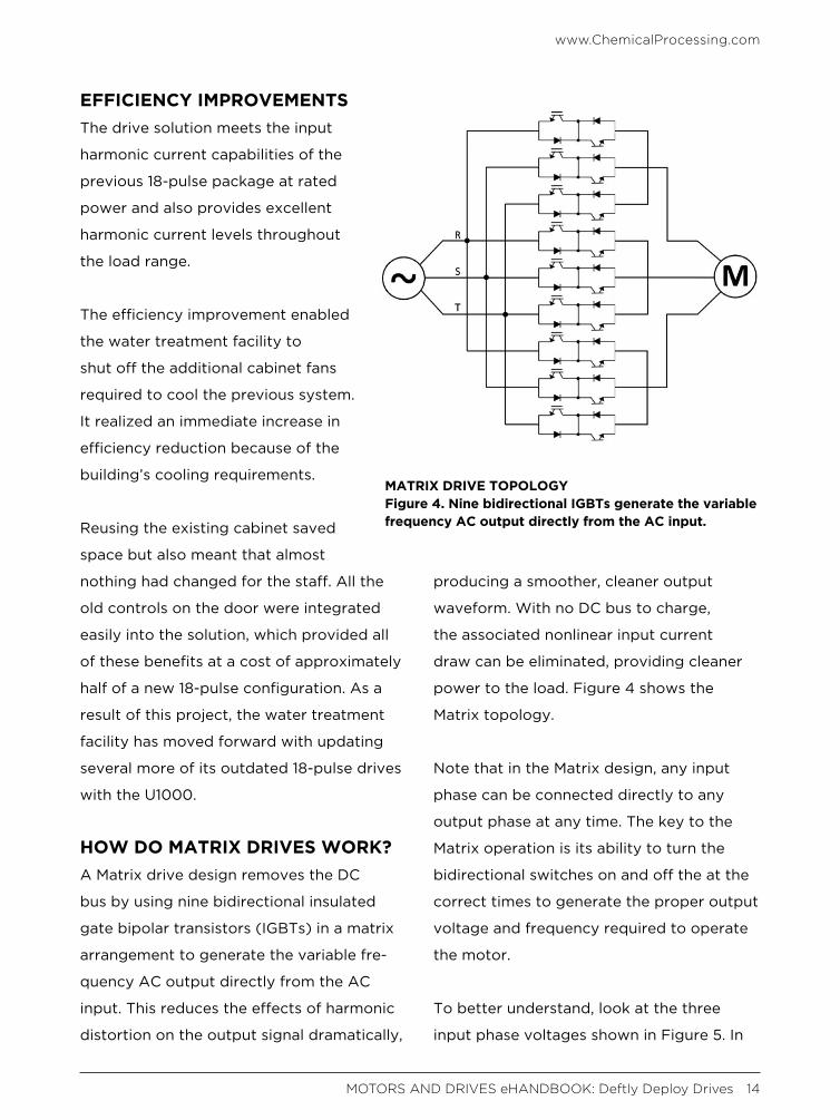
HOW DO MATRIX DRIVES WORK?A Matrix drive design removes the DC
bus by using nine bidirectional insulated
gate bipolar transistors (IGBTs) in a matrix
arrangement to generate the variable fre-
quency AC output directly from the AC
input. This reduces the effects of harmonic
distortion on the output signal dramatically,
producing a smoother, cleaner output
waveform. With no DC bus to charge,
the associated nonlinear input current
draw can be eliminated, providing cleaner
power to the load. Figure 4 shows the
Matrix topology.
Note that in the Matrix design, any input
phase can be connected directly to any
output phase at any time. The key to the
Matrix operation is its ability to turn the
bidirectional switches on and off the at the
correct times to generate the proper output
voltage and frequency required to operate
the motor.
To better understand, look at the three
input phase voltages shown in Figure 5. In
MATRIX DRIVE TOPOLOGYFigure 4. Nine bidirectional IGBTs generate the variable frequency AC output directly from the AC input.
www.ChemicalProcessing.com
MOTORS AND DRIVES eHANDBOOK: Deftly Deploy Drives 14

operation, the control built into the Matrix
variable frequency drive (VFD) monitors
the voltage difference continually between
each of the phases.
All drives use a pulse width modulation
(PWM) waveform to generate motor volt-
age, including the Matrix drive. A standard
drive pulses the DC bus to the motor to
create the output voltage waveform. The
time each pulse is ON (the pulse’s width)
helps to determine the output voltage and
final RMS voltage of each cycle of voltage.
Instead of using a DC bus, the Matrix
drive pulses the motor using its input
voltage. This is done in two steps (Figure
6). The low input voltage and mid input
voltage are used for the first step and the
mid voltage and high voltage are used
for the second step. The reverse order is
used to turn the pulse off. This process
is repeated over and over to generate
the PWM output waveform constantly
adjusted along with the ever changing
three-phase input voltage.
The constant use of the input voltage
means current constantly is being drawn.
Therefore, the Matrix drive does not
mitigate harmonics. Instead, it draws
input current naturally with less than
5% iTHD automatically as it provides
motor control.
MATRIX DRIVE REGENERATIONIn addition to the low harmonics and
near-unity power factor, the Matrix
design also provides energy savings
through regeneration.
INPUT PHASE VOLTAGESFigure 5. The Matrix drive pulses the motor using its input voltage.
MATRIX STEPPED PULSEFigure 6. A two-step process is repeated to generate the PWM output waveform.
www.ChemicalProcessing.com
MOTORS AND DRIVES eHANDBOOK: Deftly Deploy Drives 15

When a motor is being driven by a load,
as opposed to driving the load, it acts as a
generator, sending the extra power back
to the VFD. The extra regenerative energy
then is put back onto the grid to be dis-
persed to other loads on the grid, which
reduces the utility power demand. Exam-
ples include applications such as pump
jacks, in which the load oscillates between
motoring and regeneration, and downhill
conveyors that are in a continuous regen-
erative state.
In conventional drives, dynamic braking
resistors can be used to divert the regen-
erative energy away from the VFD and
prevent a DC bus overvoltage condition.
The Matrix drive’s nine bidirectional IGBTs
enable the regenerative energy to be
directed back to the supply to be credited
against the user’s power bill (Figure 7).
MONITORINGSome Matrix VFDs can monitor power
in several ways to give instant feedback
on energy saved. When provided with
the $/kwh billing rate, the display on the
drive can show the following information
on request:
• Power output
• Power consumption
• Regenerative power
• Power saved
• Power bill
CHRIS JASZCZOLT, is product manager, Matrix drives,
Yaskawa America, Inc. Drives & Motion Division. He can
be reached at [email protected].
REGENERATIVE ENERGYFigure 7. The the Matrix drive’s regenerative energy translates to power bill savings.
www.ChemicalProcessing.com
MOTORS AND DRIVES eHANDBOOK: Deftly Deploy Drives 16

JOIN US ON SOCIAL MEDIA!
Visit the lighter side, featuring drawings by award-winning
cartoonist Jerry King. Click on an image and you will arrive at a page with the winning caption and all submissions for that particular cartoon.
ADDITIONAL RESOURCESEHANDBOOKSCheck out our vast library of past eHandbooks that offer a wealth of information on a single topic,
aimed at providing best practices, key trends, developments and successful applications to help make
your facilities as efficient, safe, environmentally friendly and economically competitive as possible.
UPCOMING AND ON DEMAND WEBINARSTap into expert knowledge. Chemical Processing editors and industry experts delve into
hot topics challenging the chemical processing industry today while providing insights and
practical guidance. Each of these free webinars feature a live Q&A session and lasts 60 minutes.
WHITE PAPERSCheck out our library of white papers covering myriad topics and offering valuable insight
into products and solutions important to chemical processing professionals. From automation
to fluid handling, separations technologies and utilities, this white paper library has it all.
PODCAST: PROCESS SAFETY WITH TRISH & TRACITrish Kerin, director of IChemE Safety Centre, and Chemical Processing’s Traci Purdum discuss
current process safety issues offering insight into mitigation options and next steps.
ASK THE EXPERTSHave a question on a technical issue that needs to be addressed? Visit our Ask the Experts
forum. Covering topics from combustion to steam systems, our roster of leading subject
matter experts, as well as other forum members, can help you tackle plant issues.
MOTORS AND DRIVES eHANDBOOK: Deftly Deploy Drives 17