deicing control facilities improvements-2016 project no. i ... · deicing control facilities...
TRANSCRIPT

Deicing Control Facilities Improvements-2016 Project No. I-16-023
Indianapolis Airport Authority
Submittal Review Sheet Attached is the submittal for specification section 40 9141 Flow Process for the Deicing Control Facilities Improvements – 2016 I-16-023 project for your review and approval. Thieneman Construction has reviewed the submittal information and added the following notes for your review, approval, and consideration
Items for Engineer: 1. Siemens SITRANS FM MAG 5100W 2. Siemens FM MAG 5000 Items for Supplier: 1. Supply materials as requested by TCI in conformance with the project schedule. 2. Include two year manufacturers warranty per specification requirements. 3. Provide grounding provisions per specification requirements.
If you have any questions on this submittal information, please contact Lori Kelleher at 317-763-1634. Thieneman Construction requests your review, approval, and return of one (1) copy of the approved submittals
Project Name: Deicing Control Facilities Improvements-2016 Contractor: Thieneman Construction, Inc. Subcontractor / Supplier: BL Anderson Submittal Number: 000012 Submittal Specification Section: 40 9141 Flow Process Item 1.3.A.2 Product
Data and Item 1.3.A.3 Layout Drawings Item Description: Magnetic Flow Meter and Transmitter Quantity of Submittals: 1 – Electronic Comments: See Above Quantity of Approved Submittals to be Returned: 1 – Electronic Signature: CONTRACTOR’S CERTIFICATION Submittal material has been reviewed for compliance with specifications and drawings. Required field measurements have been verified. The work shown on this submittal has been coordinated with other submittals affected by this work. All data has been checked by the Contractor and any variations from the specifications or drawings have been noted. The work described on the submittal material is recommended by the Contractor, and the guarantee in the specifications will apply: Contractor: Thieneman Construction
Approved: Lori Kelleher
Date: 10/13/2016

Submittal for Approval
Project: Indianapolis Airport Engineer: Gresham, Smith, and Partners Contractor: Thieneman Construction Co.
Item – Siemens Magnetic Flowmeter
Quantity: (1) each Model: 5100W (Flowtube) Mag 5000 (Transmitter) Manufacturer: Siemens Description: Series 5100W electromagnetic flowmeter with interconnecting cable, submersible kit, and remote wall mounting kit Power Required: 120 VAC Output: 4-20mA Meter Electrodes: 316 stainless steel Accessories: 100’ of interconnecting cable Submersible Kit Remote Wall Mounting Kit

sitrans f
SITRANS F M MAGFLOElectromagnetic FlowmetersExplore the Siemens Solution
s
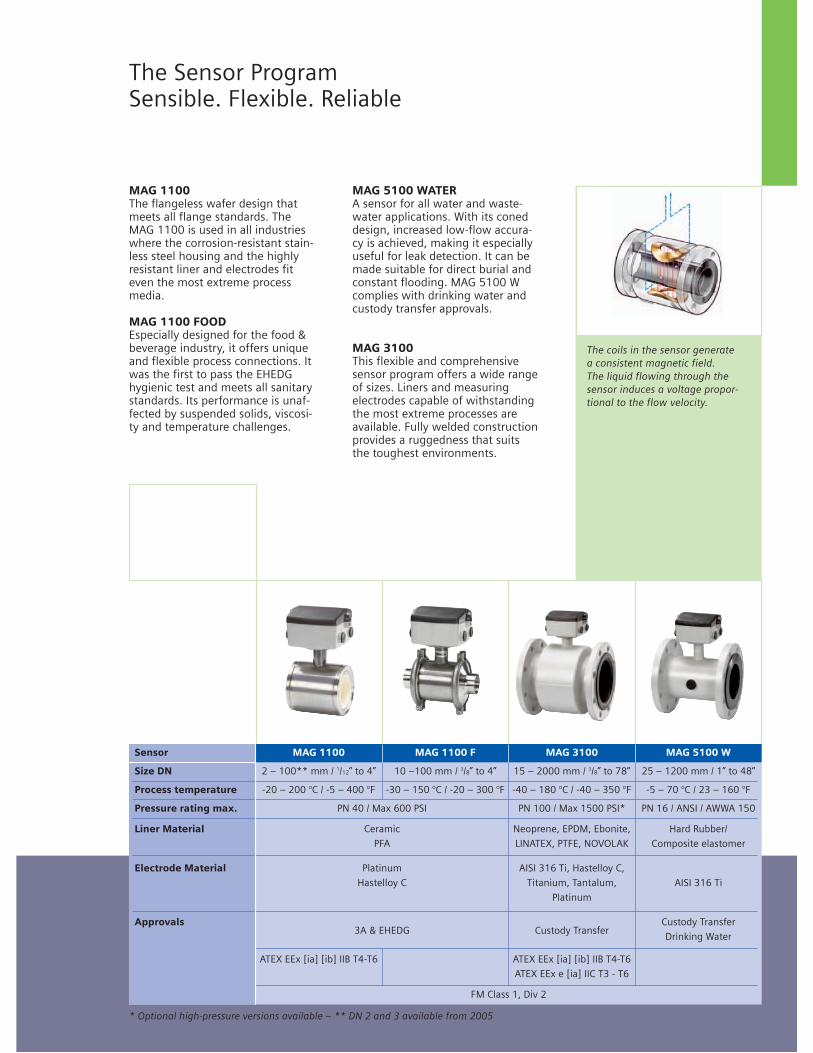
The Sensor ProgramSensible. Flexible. Reliable
The coils in the sensor generate a consistent magnetic field. The liquid flowing through thesensor induces a voltage propor-tional to the flow velocity.
MAG 1100The flangeless wafer design thatmeets all flange standards. TheMAG 1100 is used in all industrieswhere the corrosion-resistant stain-less steel housing and the highlyresistant liner and electrodes fiteven the most extreme processmedia.
MAG 1100 FOODEspecially designed for the food &beverage industry, it offers uniqueand flexible process connections. Itwas the first to pass the EHEDGhygienic test and meets all sanitarystandards. Its performance is unaf-fected by suspended solids, viscosi-ty and temperature challenges.
MAG 5100 WATERA sensor for all water and waste-water applications. With its coneddesign, increased low-flow accura-cy is achieved, making it especially useful for leak detection. It can bemade suitable for direct burial andconstant flooding. MAG 5100 Wcomplies with drinking water andcustody transfer approvals.
MAG 3100This flexible and comprehensivesensor program offers a wide rangeof sizes. Liners and measuring electrodes capable of withstandingthe most extreme processes areavailable. Fully welded constructionprovides a ruggedness that suitsthe toughest environments.
Sensor MAG 1100 MAG 1100 F MAG 3100 MAG 5100 W
Size DN 2 – 100** mm / 1/12” to 4” 10 –100 mm / 3/8” to 4” 15 – 2000 mm / 3/8” to 78” 25 – 1200 mm / 1” to 48”
Process temperature -20 – 200 °C / -5 – 400 °F -30 – 150 °C / -20 – 300 °F -40 – 180 °C / -40 – 350 °F -5 – 70 °C / 23 – 160 °F
Pressure rating max. PN 40 / Max 600 PSI PN 100 / Max 1500 PSI* PN 16 / ANSI / AWWA 150
Liner Material Ceramic Neoprene, EPDM, Ebonite, Hard Rubber/
PFA LINATEX, PTFE, NOVOLAK Composite elastomer
Electrode Material Platinum AISI 316 Ti, Hastelloy C,
Hastelloy C Titanium, Tantalum, AISI 316 Ti
Platinum
Approvals3A & EHEDG Custody Transfer
Custody Transfer
Drinking Water
ATEX EEx [ia] [ib] IIB T4-T6 ATEX EEx [ia] [ib] IIB T4-T6
ATEX EEx e [ia] IIC T3 - T6
FM Class 1, Div 2
* Optional high-pressure versions available – ** DN 2 and 3 available from 2005

Flow MeasurementSITRANS F M
Flow sensor MAG 5100 W
4/68 Siemens FI 01 · 2011
4
■ Overview
The SITRANS F M MAG 5100 W is an electromagnetic flow sen-sor designed to meet ground water, drinking water, waste water, sewage or sludge applications.
■ Benefits
• DN 15 to DN 1200 / 2000 (½” to 48" / 78”)• Stock program of MAG 5100 W secures short delivery time• Connection flanges EN 1092-1 (DIN 2501), ANSI, AWWA, AS
and JIS.• NBR Hard Rubber and Ebonite Hard Rubber liner for all water
applications• EPDM liner with drinking water approvals• Hastelloy integrated grounding and measuring electrodes• Increased low flow accuracy for water leak detection, due to
coned liner design (Order No. 7ME6520, DN 15 to 300 mm (½" to 12")).
• Drinking water approvals• Suitable for direct burial and constant flooding• Custody transfer approvals• Build-in length according to ISO 13359• Easy commissioning, SENSORPROM unit automatically up-
loads calibration values and settings.• Designed so patented in-situ verification can be conducted.
Using SENSORPROM fingerprint.• Custody Transfer option for water billing, with type approval af-
ter OIML R49 and verified according to MI-001 for DN 50 (2") to DN 300 (12")- Pattern approval OIML R 49 (Denmark, Germany) - conforms to ISO 4064 and EN 14154- MI-001 Custody Transfer approval for billing (EU)
• Meets EEC directives: PED, 97/23/EC pressure directive for EN1092-1 flanges
• Simple onsite or factory upgrade to IP68/NEMA 6P of a stan-dard sensor
• MCERTS approval for UK environmental market
■ Application
The main applications of the SITRANS F M electromagnetic flow sensors can be found in the following fields:• Water abstraction• Water treatment• Water distribution network (leak detection management)• Custody transfer water meters• Irrigation• Waste water treatment• Filtration plant (e.g. reverse osmosis and ultra filtration)• Industrial water applications
■ Mode of operation
The flow measuring principle is based on Faradays law of elec-tromagnetic induction according to which the sensor converts the flow into an electrical voltage proportional to the velocity of the flow.
■ Integration
The complete flowmeter consists of a flow sensor and an asso-ciated transmitter SITRANS F M MAG 5000, MAG 6000 or MAG 6000 I.
The flexible communication concept USM II simplifies integra-tion and update to a variety of fieldbus systems, e.g. HART, De-viceNet, PROFIBUS DP and PA, FOUNDATION Fieldbus H1, Modbus RTU/RS485.
© Siemens AG 2010
Flow MeasurementSITRANS F M
Flow sensor MAG 5100 W
4/69Siemens FI 01 · 2011
4
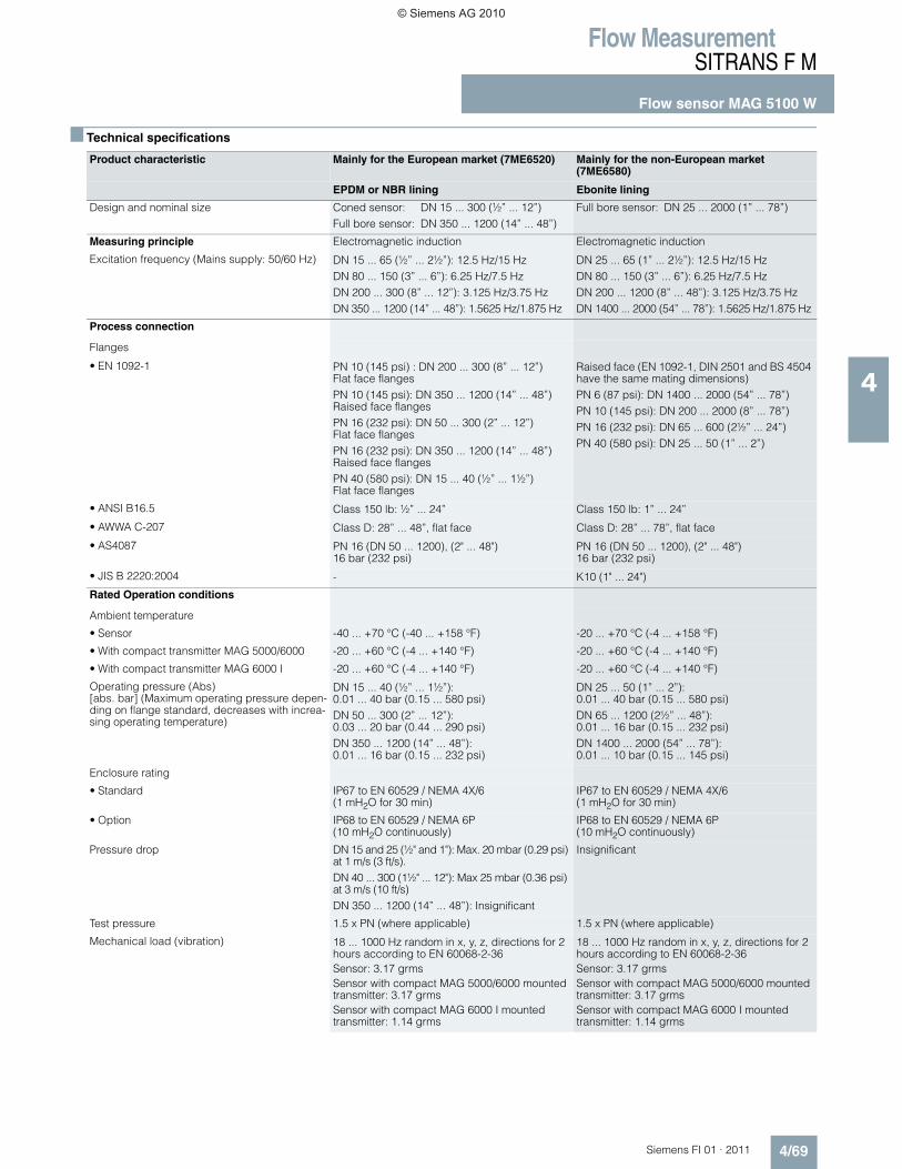
■ Technical specifications
Product characteristic Mainly for the European market (7ME6520) Mainly for the non-European market(7ME6580)
EPDM or NBR lining Ebonite lining
Design and nominal size Coned sensor: DN 15 ... 300 (½” ... 12”)Full bore sensor: DN 350 ... 1200 (14” ... 48”)
Full bore sensor: DN 25 ... 2000 (1” ... 78”)
Measuring principle Electromagnetic induction Electromagnetic induction
Excitation frequency (Mains supply: 50/60 Hz) DN 15 ... 65 (½” ... 2½”): 12.5 Hz/15 HzDN 80 ... 150 (3” ... 6”): 6.25 Hz/7.5 HzDN 200 ... 300 (8” ... 12”): 3.125 Hz/3.75 HzDN 350 ... 1200 (14” ... 48”): 1.5625 Hz/1.875 Hz
DN 25 ... 65 (1” ... 2½”): 12.5 Hz/15 HzDN 80 ... 150 (3” ... 6”): 6.25 Hz/7.5 HzDN 200 ... 1200 (8” ... 48”): 3.125 Hz/3.75 HzDN 1400 ... 2000 (54” ... 78”): 1.5625 Hz/1.875 Hz
Process connection
Flanges
• EN 1092-1 PN 10 (145 psi) : DN 200 ... 300 (8” ... 12”) Flat face flangesPN 10 (145 psi): DN 350 ... 1200 (14” ... 48”)Raised face flangesPN 16 (232 psi): DN 50 ... 300 (2” ... 12”)Flat face flangesPN 16 (232 psi): DN 350 ... 1200 (14” ... 48”)Raised face flangesPN 40 (580 psi): DN 15 ... 40 (½” ... 1½”)Flat face flanges
Raised face (EN 1092-1, DIN 2501 and BS 4504 have the same mating dimensions)PN 6 (87 psi): DN 1400 ... 2000 (54” ... 78”)PN 10 (145 psi): DN 200 ... 2000 (8” ... 78”)PN 16 (232 psi): DN 65 ... 600 (2½” ... 24”)PN 40 (580 psi): DN 25 ... 50 (1” ... 2”)
• ANSI B16.5 Class 150 lb: ½” ... 24” Class 150 lb: 1” ... 24”
• AWWA C-207 Class D: 28” ... 48”, flat face Class D: 28” ... 78”, flat face
• AS4087 PN 16 (DN 50 ... 1200), (2" ... 48") 16 bar (232 psi)
PN 16 (DN 50 ... 1200), (2" ... 48") 16 bar (232 psi)
• JIS B 2220:2004 - K10 (1" ... 24")
Rated Operation conditions
Ambient temperature
• Sensor -40 ... +70 °C (-40 ... +158 °F) -20 ... +70 °C (-4 ... +158 °F)
• With compact transmitter MAG 5000/6000 -20 ... +60 °C (-4 ... +140 °F) -20 ... +60 °C (-4 ... +140 °F)
• With compact transmitter MAG 6000 I -20 ... +60 °C (-4 ... +140 °F) -20 ... +60 °C (-4 ... +140 °F)
Operating pressure (Abs) [abs. bar] (Maximum operating pressure depen-ding on flange standard, decreases with increa-sing operating temperature)
DN 15 ... 40 (½” ... 1½”): 0.01 ... 40 bar (0.15 ... 580 psi)DN 50 ... 300 (2” ... 12”): 0.03 ... 20 bar (0.44 ... 290 psi)DN 350 ... 1200 (14” ... 48”): 0.01 ... 16 bar (0.15 ... 232 psi)
DN 25 ... 50 (1” ... 2”):0.01 ... 40 bar (0.15 ... 580 psi)DN 65 ... 1200 (2½” ... 48”):0.01 ... 16 bar (0.15 ... 232 psi)DN 1400 ... 2000 (54” ... 78”):0.01 ... 10 bar (0.15 ... 145 psi)
Enclosure rating
• Standard IP67 to EN 60529 / NEMA 4X/6 (1 mH2O for 30 min)
IP67 to EN 60529 / NEMA 4X/6 (1 mH2O for 30 min)
• Option IP68 to EN 60529 / NEMA 6P (10 mH2O continuously)
IP68 to EN 60529 / NEMA 6P (10 mH2O continuously)
Pressure drop DN 15 and 25 (½" and 1"): Max. 20 mbar (0.29 psi) at 1 m/s (3 ft/s).DN 40 ... 300 (1½" ... 12"): Max 25 mbar (0.36 psi) at 3 m/s (10 ft/s)DN 350 ... 1200 (14” ... 48”): Insignificant
Insignificant
Test pressure 1.5 x PN (where applicable) 1.5 x PN (where applicable)
Mechanical load (vibration) 18 ... 1000 Hz random in x, y, z, directions for 2 hours according to EN 60068-2-36Sensor: 3.17 grmsSensor with compact MAG 5000/6000 mounted transmitter: 3.17 grmsSensor with compact MAG 6000 I mounted transmitter: 1.14 grms
18 ... 1000 Hz random in x, y, z, directions for 2 hours according to EN 60068-2-36Sensor: 3.17 grmsSensor with compact MAG 5000/6000 mounted transmitter: 3.17 grmsSensor with compact MAG 6000 I mounted transmitter: 1.14 grms
© Siemens AG 2010
Flow MeasurementSITRANS F M
Flow sensor MAG 5100 W
4/73Siemens FI 01 · 2011
4
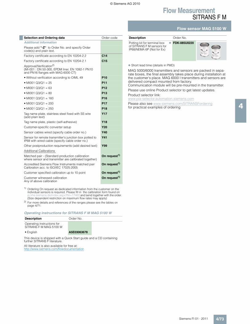
1) Ordering On request as dedicated information from the customer on the individual sensors is required. Please fill in the calibration form found on pi.khe.siemens.de/index.aspx?Nr=17460 and send together with the order. (Size dependent restriction on maximum flow rates may apply)
2) For more details and references of the ranges please see the tables on page 4/71.
Operating instructions for SITRANS F M MAG 5100 W
This device is shipped with a Quick Start guide and a CD containing further SITRANS F literature.
All literature is also available for free at: http://www.siemens.com/flowdocumentation
,
◆ Short lead time (details in PMD)
MAG 5000/6000 transmitters and sensors are packed in sepa-rate boxes, the final assembly takes place during installation at the customer's place. MAG 6000 I transmitters and sensors are delivered compact mounted from factory.Communication module will be pre-mounted in the transmitter.Please use online Product selector to get latest updates.Product selector link: www.pia-selector.automation.siemens.comPlease also see www.siemens.com/SITRANSForderingfor practical examples of ordering
Selection and Ordering data Order code
Additional information
Please add “-Z“ to Order No. and specify Order code(s) and plain text.
Factory certificate according to EN 10204-2.2 C14
Factory certificate according to EN 10204-2.1 C15
Approval/Verification2)
(MI-001 : DN 50-300, EPDM liner, EN 1092-1 PN10 and PN16 flanges with MAG 6000 CT)
• Without verification according to OIML 49 P10
• MI001 Q3/Q1 = 25 P11
• MI001 Q3/Q1 = 63 P12
• MI001 Q3/Q1 = 80 P13
• MI001 Q3/Q1 = 160 P16
• MI001 Q3/Q1 = 200 P17
• MI001 Q3/Q1 = 250 P18
Tag name plate, stainless steel fixed with SS wire (add plain text)
Y17
Tag name plate, plastic (self-adhesive) Y18
Customer-specific converter setup Y20
Sensor cables wired (specify cable order no.) Y40
Sensor for remote transmitter's junction box potted to IP68 with wired cable (specify cable order no.)
Y41
Other postproduction requirements (add desired text) Y99
Additional Calibrations
Matched pair - (Standard production calibration where sensor and transmitter are calibrated together)
On request1)
Accredited Siemens Flow Instruments matched pair Calibration acc. to ISO/IEC 17025:2005
On request1)
Customer specified calibration up to 10 point On request1)
Customer witnessed calibrationAny of above calibration
On request1)
Description Order No.
Operating instructions for SITRANS F M MAG 5100 W
• English A5E03063678
Description Order No.
Potting kit for terminal box of SITRANS F M sensors for IP68/NEMA 6P (Not for Ex)
◆ FDK-085U0220
© Siemens AG 2010
Flow MeasurementSITRANS F M
Flow sensor MAG 5100 W
4/74 Siemens FI 01 · 2011
4
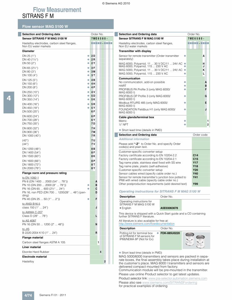
◆ Short lead time (details in PMD)
Operating instructions for SITRANS F M MAG 5100 W
This device is shipped with a Quick Start guide and a CD containing further SITRANS F literature.
All literature is also available for free at: http://www.siemens.com/flowdocumentation,
◆ Short lead time (details in PMD)MAG 5000/6000 transmitters and sensors are packed in sepa-rate boxes, the final assembly takes place during installation at the customer's place. MAG 6000 I transmitters and sensors are delivered compact mounted from factory.Communication module will be pre-mounted in the transmitter.Please use online Product selector to get latest updates.Product selector link: www.pia-selector.automation.siemens.comPlease also see www.siemens.com/SITRANSForderingfor practical examples of ordering
Selection and Ordering data Order No.
Sensor SITRANS F M MAG 5100 W 7 M E 6 5 8 0 -
Hastelloy electrodes, carbon steel flanges, Non EU water markets
77777 - 7777
Diameter
DN 25 (1“) ◆ 2 DDN 40 (1½“) ◆ 2 RDN 50 (2“) ◆ 2 Y
DN 65 (2½“) ◆ 3 FDN 80 (3“) ◆ 3 MDN 100 (4“) ◆ 3 T
DN 125 (5“) ◆ 4 BDN 150 (6“) ◆ 4 HDN 200 (8“) ◆ 4 P
DN 250 (10“) ◆ 4 VDN 300 (12“) ◆ 5 DDN 350 (14“) ◆ 5 K
DN 400 (16“) ◆ 5 RDN 450 (18“) ◆ 5 YDN 500 (20“) 6 F
DN 600 (24“) 6 PDN 700 (28“) 6 YDN 750 (30“) 7 D
DN 800 (32“) 7 HDN 900 (36“) 7 MDN 1000 (40“) 7 R
(42“) 7 U(44“) 7 V
DN 1200 (48“) 8 BDN 1400 (54“) 8 FDN 1500 (60“) 8 K
DN 1600 (66“) 8 PDN 1800 (72“) 8 TDN 2000 (78“) 8 Y
Flange norm and pressure rating
to EN 1092-1PN 6 (DN 1400 ... 2000 (54“ ... 78“)) APN 10 (DN 200 ... 2000 (8“ ... 78“)) ◆ BPN 16 (DN 65 ... 600 (2½“ ... 24“) ◆ CPN 16, non PED (DN 700 ... 1200/28“ ... 48“) (pen-ding)
D
PN 40 (DN 25 ... 50 (1“ ... 2“)) ◆ F
to ANSI B16.5class 150 (1“ ... 24“) J
to AWWA C-207Class D (28“ ... 78“) L
to AS 4087PN 16 (DN 50 ... 1200 (2" ... 48")) N
to JISB 2220:2004 K10 (1" ... 24") R
Flange material
Carbon steel flanges ASTM A 105 1
Liner material
Ebonite Hard Rubber 4
Electrode material
Hastelloy 2
Transmitter with display
Sensor for remote transmitter (Order transmitter separately)
◆ A
MAG 6000, Polyamid, 11 ... 30 V DC/11 ... 24V AC ◆ HMAG 6000, Polyamid, 115 ... 230 V AC ◆ JMAG 5000, Polyamid, 11 ... 30 V DC/11 ... 24V AC ◆ KMAG 5000, Polyamid, 115 ... 230 V AC ◆ L
CommunicationNo communication, add-on possible ◆ AHART ◆ BPROFIBUS PA Profile 3 (only MAG 6000/MAG 6000 I)
◆ F
PROFIBUS DP Profile 3 (only MAG 6000/MAG 6000 I)
◆ G
Modbus RTU/RS 485 (only MAG 6000/MAG 6000 I)
◆ E
FOUNDATION Fieldbus H1 (only MAG 6000/MAG 6000 I)
◆ J
Cable glands/terminal boxMetric ◆ 1½" NPT ◆ 2
Selection and Ordering data Order code
Additional information
Please add “-Z“ to Order No. and specify Order code(s) and plain text.
Customer-specific converter setupFactory certificate according to EN 10204-2.2 C14Factory certificate according to EN 10204-2.1 C15Tag name plate, stainless steel fixed with SS wire Y17Tag name plate, plastic (self-adhesive) Y18Customer-specific converter setup Y20Sensor cables wired (specify cable order no.) Y40Sensor for remote transmitter's junction box potted to IP68 with wired cable (specify cable order no.)
Y41
Other postproduction requirements (add desired text) Y99
Description Order No.
Operating instructions for SITRANS F M MAG 5100 W• English A5E03063678
Description Order No.
Potting kit for terminal box of SITRANS F M sensors for IP68/NEMA 6P (Not for Ex)
◆ FDK-085U0220
Selection and Ordering data Order No.
Sensor SITRANS F M MAG 5100 W 7 M E 6 5 8 0 -
Hastelloy electrodes, carbon steel flanges, Non EU water markets
77777 - 7777
© Siemens AG 2010
Flow MeasurementSITRANS F M
Flow sensor MAG 5100 W
4/75Siemens FI 01 · 2011
4
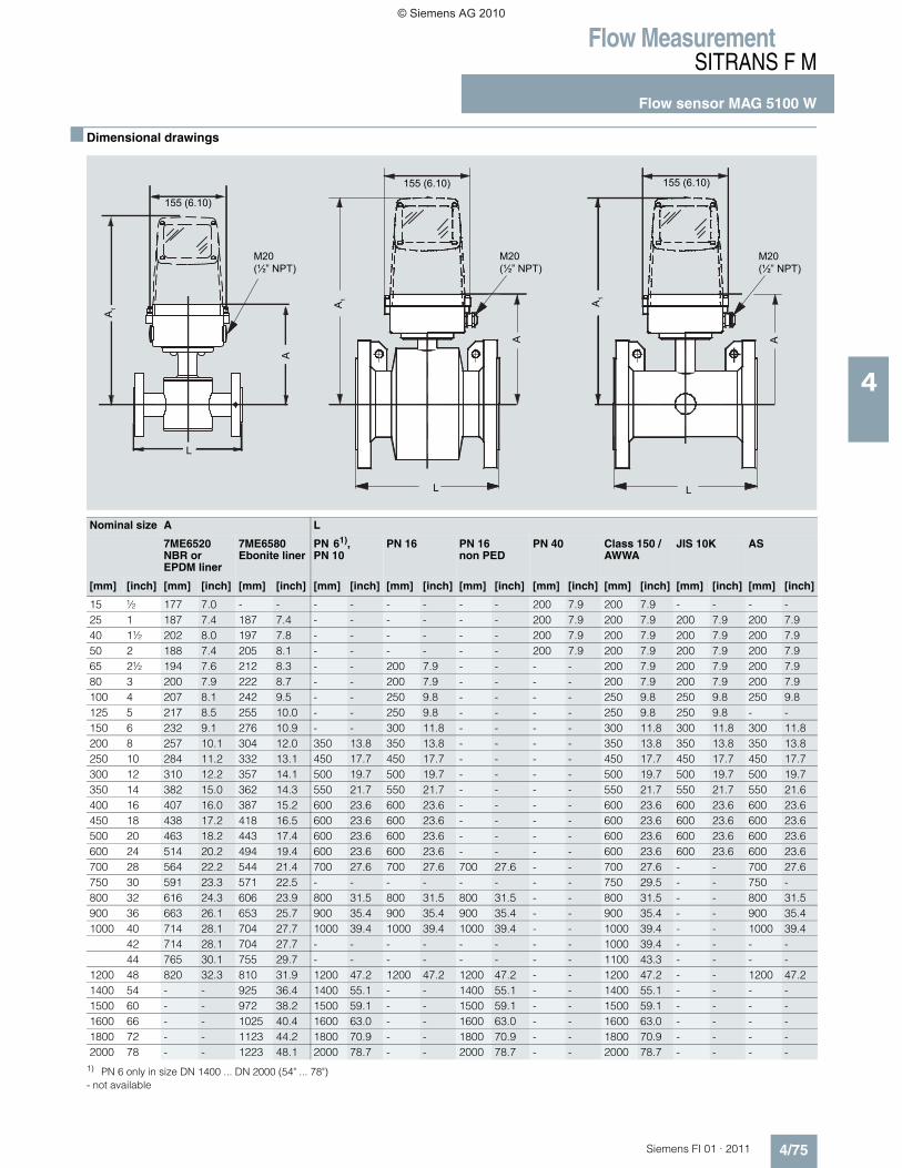
■ Dimensional drawings
- not available
155 (6.10)
L
M20(½” NPT)
M20(½” NPT)
M20(½” NPT)
L
A
L
A
A1
155 (6.10) 155 (6.10)
A1
A1
ANominal size A L
7ME6520NBR or EPDM liner
7ME6580Ebonite liner
PN 61), PN 10
PN 16 PN 16 non PED
PN 40 Class 150 / AWWA
JIS 10K AS
[mm] [inch] [mm] [inch] [mm] [inch] [mm] [inch] [mm] [inch] [mm] [inch] [mm] [inch] [mm] [inch] [mm] [inch] [mm] [inch]
15 ½ 177 7.0 - - - - - - - - 200 7.9 200 7.9 - - - -25 1 187 7.4 187 7.4 - - - - - - 200 7.9 200 7.9 200 7.9 200 7.940 1½ 202 8.0 197 7.8 - - - - - - 200 7.9 200 7.9 200 7.9 200 7.950 2 188 7.4 205 8.1 - - - - - - 200 7.9 200 7.9 200 7.9 200 7.965 2½ 194 7.6 212 8.3 - - 200 7.9 - - - - 200 7.9 200 7.9 200 7.980 3 200 7.9 222 8.7 - - 200 7.9 - - - - 200 7.9 200 7.9 200 7.9100 4 207 8.1 242 9.5 - - 250 9.8 - - - - 250 9.8 250 9.8 250 9.8125 5 217 8.5 255 10.0 - - 250 9.8 - - - - 250 9.8 250 9.8 - -150 6 232 9.1 276 10.9 - - 300 11.8 - - - - 300 11.8 300 11.8 300 11.8200 8 257 10.1 304 12.0 350 13.8 350 13.8 - - - - 350 13.8 350 13.8 350 13.8250 10 284 11.2 332 13.1 450 17.7 450 17.7 - - - - 450 17.7 450 17.7 450 17.7300 12 310 12.2 357 14.1 500 19.7 500 19.7 - - - - 500 19.7 500 19.7 500 19.7350 14 382 15.0 362 14.3 550 21.7 550 21.7 - - - - 550 21.7 550 21.7 550 21.6400 16 407 16.0 387 15.2 600 23.6 600 23.6 - - - - 600 23.6 600 23.6 600 23.6450 18 438 17.2 418 16.5 600 23.6 600 23.6 - - - - 600 23.6 600 23.6 600 23.6500 20 463 18.2 443 17.4 600 23.6 600 23.6 - - - - 600 23.6 600 23.6 600 23.6600 24 514 20.2 494 19.4 600 23.6 600 23.6 - - - - 600 23.6 600 23.6 600 23.6700 28 564 22.2 544 21.4 700 27.6 700 27.6 700 27.6 - - 700 27.6 - - 700 27.6750 30 591 23.3 571 22.5 - - - - - - - - 750 29.5 - - 750 -800 32 616 24.3 606 23.9 800 31.5 800 31.5 800 31.5 - - 800 31.5 - - 800 31.5900 36 663 26.1 653 25.7 900 35.4 900 35.4 900 35.4 - - 900 35.4 - - 900 35.41000 40 714 28.1 704 27.7 1000 39.4 1000 39.4 1000 39.4 - - 1000 39.4 - - 1000 39.4
42 714 28.1 704 27.7 - - - - - - - - 1000 39.4 - - - -44 765 30.1 755 29.7 - - - - - - - - 1100 43.3 - - - -
1200 48 820 32.3 810 31.9 1200 47.2 1200 47.2 1200 47.2 - - 1200 47.2 - - 1200 47.21400 54 - - 925 36.4 1400 55.1 - - 1400 55.1 - - 1400 55.1 - - - -1500 60 - - 972 38.2 1500 59.1 - - 1500 59.1 - - 1500 59.1 - - - -1600 66 - - 1025 40.4 1600 63.0 - - 1600 63.0 - - 1600 63.0 - - - -1800 72 - - 1123 44.2 1800 70.9 - - 1800 70.9 - - 1800 70.9 - - - -2000 78 - - 1223 48.1 2000 78.7 - - 2000 78.7 - - 2000 78.7 - - - -
1) PN 6 only in size DN 1400 ... DN 2000 (54" ... 78")
© Siemens AG 2010

Flow MeasurementSITRANS F M
Flow sensor MAG 5100 W
4/76 Siemens FI 01 · 2011
4
MAG 5100 W / 6000 I Compact
- not available
208 (8.19)2 x M25
208 (8.19)
155 (6.10)
208 (8.19)
155 (6.10)155 (6.10)
A
M20(½” NPT)
2 x M252 x M25
M20(½” NPT)
M20(½” NPT)
L L
A
L
A
A1
A1 A
1
Nominal size
A A1 L
7ME6520NBR or EPDM liner
7ME6580Ebonite liner
7ME6520NBR or EPDM liner
7ME6580Ebonite liner
PN 10 PN 16 PN 16non PED
PN 40 Class 150 / AWWA
JIS 10K AS
[mm] [inch] [mm] [inch] [mm] [inch] [mm] [inch] [mm] [inch] [mm] [inch] [mm] [inch] [mm] [inch] [mm] [inch] [mm] [inch] [mm] [inch] [mm] [inch]
15 ½ 177 7.0 - - - - - - - - - - - - 200 7.9 200 7.9 - - - -25 1 187 7.4 187 7.4 340 13.4 338 13.3 - - - - - - 200 7.9 200 7.9 200 7.9 200 7.940 1½ 202 8.0 197 7.8 350 13.8 348 13.7 - - - - - - 200 7.9 200 7.9 200 7.9 200 7.950 2 188 7.4 205 8.1 341 13.4 356 14.0 - - - - - - 200 7.9 200 7.9 200 7.9 200 7.965 2½ 194 7.6 212 8.3 347 13.7 363 14.3 - - 200 7.9 200 7.9 - - 200 7.9 200 7.9 200 7.980 3 200 7.9 222 8.7 353 13.9 373 14.7 - - 200 7.9 200 7.9 - - 200 7.9 200 7.9 200 7.9100 4 207 8.1 242 9.5 360 14.2 393 15.5 - - 250 9.8 250 9.8 - - 250 9.8 250 9.8 250 9.8125 5 217 8.5 255 10.0 370 14.6 406 16.0 - - 250 9.8 250 9.8 - - 250 9.8 250 9.8 - -150 6 232 9.1 276 10.9 385 15.2 427 16.8 - - 300 11.8 300 11.8 - - 300 11.8 300 11.8 300 11.8200 8 257 10.1 304 12.0 410 16.1 455 17.9 350 13.8 350 13.8 350 13.8 - - 350 13.8 350 13.8 350 13.8250 10 284 11.2 332 13.1 437 17.2 483 19.0 450 17.7 450 17.7 450 17.7 - - 450 17.7 450 17.7 450 17.7300 12 310 12.2 357 14.1 463 18.2 508 20.0 500 19.7 500 19.7 500 19.7 - - 500 19.7 500 19.7 500 19.7350 14 382 15.0 362 14.3 535 21.1 513 20.2 550 21.7 550 21.7 550 21.7 - - 550 21.7 550 21.7 550 21.7400 16 407 16.0 387 15.2 560 22.1 538 21.2 600 23.6 600 23.6 600 23.6 - - 600 23.6 600 23.6 600 23.6450 18 438 17.2 418 16.5 591 23.3 569 22.4 600 23.6 600 23.6 600 23.6 - - 600 23.6 600 23.6 600 23.6500 20 463 18.2 443 17.4 616 24.3 594 23.4 600 23.6 600 23.6 600 23.6 - - 600 23.6 600 23.6 600 23.6600 24 514 20.2 494 19.4 667 26.3 645 25.4 600 23.6 600 23.6 600 23.6 - - 600 23.6 600 23.6 600 23.6700 28 564 22.2 544 21.4 717 28.2 695 27.4 700 27.6 700 27.6 700 27.6 - - 700 27.6 - - 700 27.6750 30 591 23.3 571 22.5 744 29.3 722 28.4 - - - - - - - - 750 29.5 - - 750 -800 32 616 24.3 606 23.9 779 30.7 757 29.8 800 31.5 800 31.5 800 31.5 - - 800 31.5 - - 800 31.5900 36 663 26.1 653 25.7 826 32.5 804 31.7 900 35.4 900 35.4 900 35.4 - - 900 35.4 - - 900 35.41000 40 714 28.1 704 27.7 877 34.5 906 35.7 1000 39.4 1000 39.4 1000 39.4 - - 1000 39.4 - - 1000 39.4
42 714 28.1 704 27.7 877 34.5 - - - - - - - - - - 1000 39.4 - - - -44 765 30.1 755 29.7 928 36.5 906 35.7 - - - - - - - - 1100 43.3 - - - -
1200 48 820 32.3 810 31.9 983 38.7 961 37.8 1200 47.2 1200 47.2 1200 47.2 - - 1200 47.2 - - 1200 47.21400 54 - - 925 36.4 - - 1076 42.4 1400 55.1 - - 1400 55.1 - - 1400 55.1 - - - -1500 60 - - 972 38.2 - - 1123 44.2 1500 59.1 - - 1500 59.1 - - 1500 59.1 - - - -1600 66 - - 1025 40.4 - - 1176 46.3 1600 63.0 - - 1600 63.0 - - 1600 63.0 - - - -1800 72 - - 1123 44.2 - - 1274 50.2 1800 70.9 - - 1800 70.9 - - 1800 70.9 - - - -2000 78 - - 1223 48.1 - - 1374 54.1 2000 78.7 - - 2000 78.7 - - 2000 78.7 - - - -
© Siemens AG 2010
Flow MeasurementSITRANS F M
Flow sensor MAG 5100 W
4/77Siemens FI 01 · 2011
4
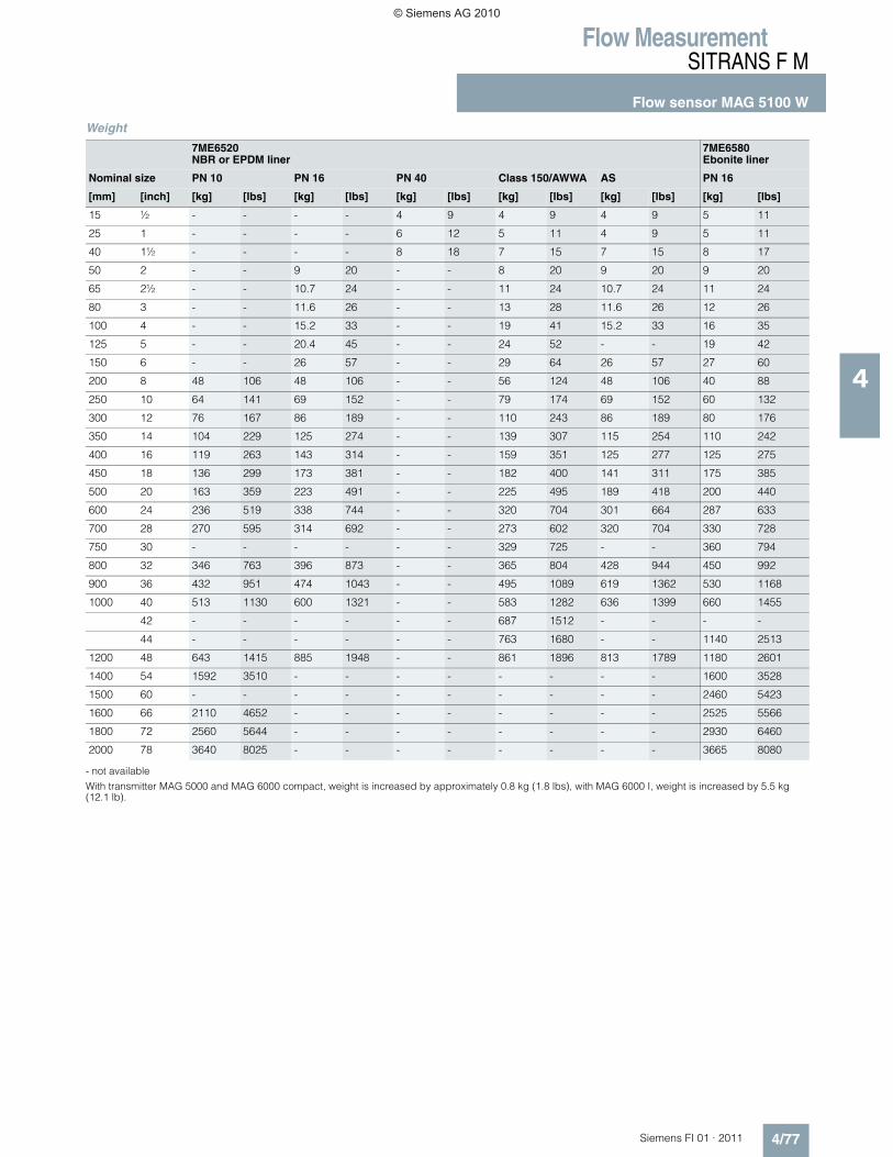
Weight
- not available
With transmitter MAG 5000 and MAG 6000 compact, weight is increased by approximately 0.8 kg (1.8 lbs), with MAG 6000 I, weight is increased by 5.5 kg (12.1 lb).
7ME6520NBR or EPDM liner
7ME6580Ebonite liner
Nominal size PN 10 PN 16 PN 40 Class 150/AWWA AS PN 16
[mm] [inch] [kg] [lbs] [kg] [lbs] [kg] [lbs] [kg] [lbs] [kg] [lbs] [kg] [lbs]
15 ½ - - - - 4 9 4 9 4 9 5 11
25 1 - - - - 6 12 5 11 4 9 5 11
40 1½ - - - - 8 18 7 15 7 15 8 17
50 2 - - 9 20 - - 8 20 9 20 9 20
65 2½ - - 10.7 24 - - 11 24 10.7 24 11 24
80 3 - - 11.6 26 - - 13 28 11.6 26 12 26
100 4 - - 15.2 33 - - 19 41 15.2 33 16 35
125 5 - - 20.4 45 - - 24 52 - - 19 42
150 6 - - 26 57 - - 29 64 26 57 27 60
200 8 48 106 48 106 - - 56 124 48 106 40 88
250 10 64 141 69 152 - - 79 174 69 152 60 132
300 12 76 167 86 189 - - 110 243 86 189 80 176
350 14 104 229 125 274 - - 139 307 115 254 110 242
400 16 119 263 143 314 - - 159 351 125 277 125 275
450 18 136 299 173 381 - - 182 400 141 311 175 385
500 20 163 359 223 491 - - 225 495 189 418 200 440
600 24 236 519 338 744 - - 320 704 301 664 287 633
700 28 270 595 314 692 - - 273 602 320 704 330 728
750 30 - - - - - - 329 725 - - 360 794
800 32 346 763 396 873 - - 365 804 428 944 450 992
900 36 432 951 474 1043 - - 495 1089 619 1362 530 1168
1000 40 513 1130 600 1321 - - 583 1282 636 1399 660 1455
42 - - - - - - 687 1512 - - - -
44 - - - - - - 763 1680 - - 1140 2513
1200 48 643 1415 885 1948 - - 861 1896 813 1789 1180 2601
1400 54 1592 3510 - - - - - - - - 1600 3528
1500 60 - - - - - - - - - - 2460 5423
1600 66 2110 4652 - - - - - - - - 2525 5566
1800 72 2560 5644 - - - - - - - - 2930 6460
2000 78 3640 8025 - - - - - - - - 3665 8080
© Siemens AG 2010
MAGFLO� Product selection guidelines
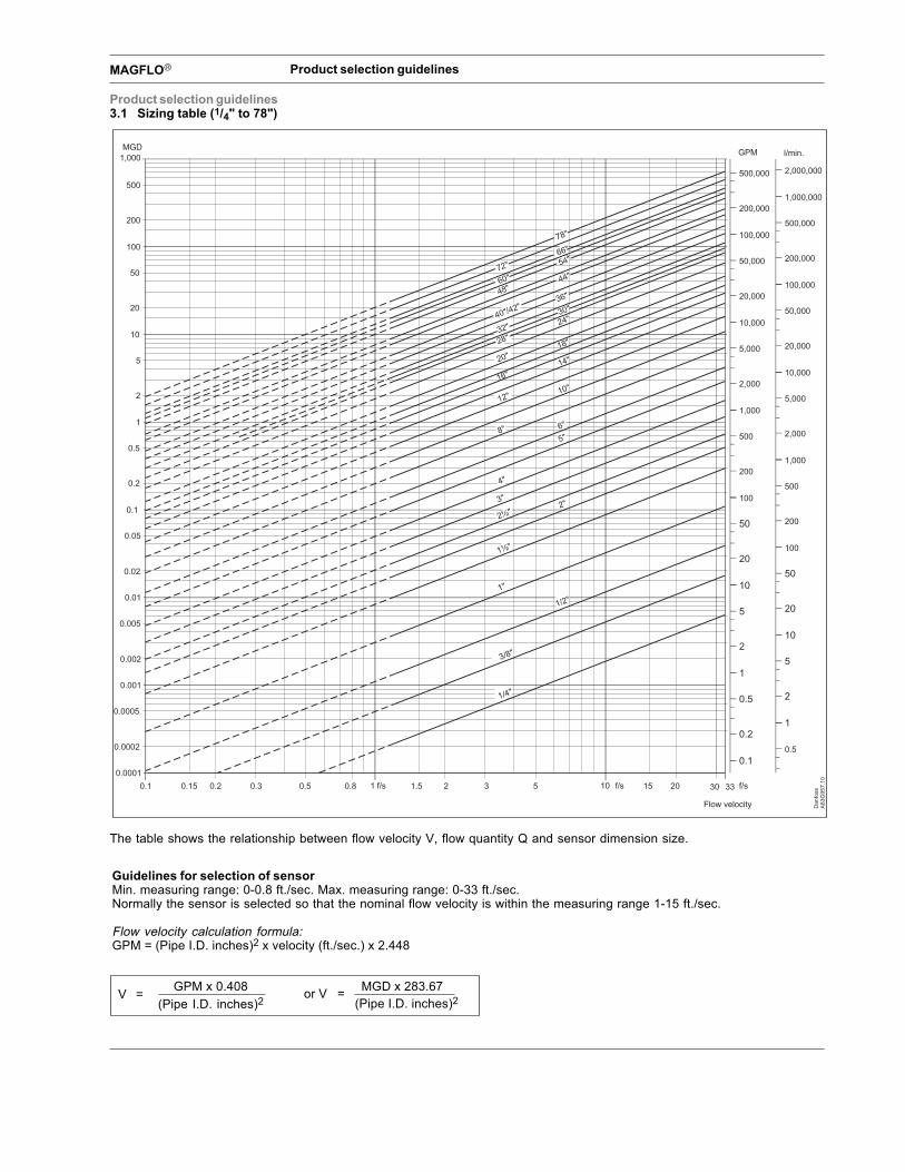
Product selection guidelines3.1 Sizing table (1/4" to 78")
The table shows the relationship between flow velocity V, flow quantity Q and sensor dimension size.
Guidelines for selection of sensorMin. measuring range: 0-0.8 ft./sec. Max. measuring range: 0-33 ft./sec.Normally the sensor is selected so that the nominal flow velocity is within the measuring range 1-15 ft./sec.
Flow velocity calculation formula:GPM = (Pipe I.D. inches)2 x velocity (ft./sec.) x 2.448
V = GPM x 0.408(Pipe I.D. inches)2
or V = (Pipe I.D. inches)2
MGD x 283.67

The Transmitter ProgramWhat’s right for you?
MAG 5000 and MAG 6000For high performance, easy operation and reducedmaintenance.MAG 5000 is the truly robust solu-tion for all-around applications. MAG 6000 is for the more deman-ding applications where higheraccuracy and greater functionalityis required.
MAG 6000 IndustryThis transmitter is designed for the special demands in the processindustry. The robust, full-metalhousing provides superb protec-tion, even in the harshest industrialenvironments. Full input and out-put functionality is given even inthe ATEX EEx d version.
Guaranteed Performance• Compact or Remote Installation• Superior signal resolution for
optimized turn-down ratio• Digital Signal Processing with
unlimited possibilities• User configurable operation
menu with password protection
• Multiple functional output for process control
• Self-diagnostics for error detection and logging
• Batch control• Multi-lingual display and
keypad • Custody Transfer Approved • Electrode cleaning accessory
option
SENSORPROMEach flow meter has its own identi-ty stored in the SENSORPROM.
The information consists of:• Calibration data• "Fingerprint" – magnetism
properties• User setup and programming
data
The individual calibration and fin-gerprint data are pre-programmedat the factory, whereas the setupdata are customer-specific. Thisunique combination ensures a costeffective, easy and error-free instal-lation.
"Plug & Play" Communication ModulesUSM II (Universal Signal Module) is "Plug & Play" at itsvery best. It makes flowmeter networking installationand configuration easy.
And it is compatible with virtually every communicationstandard used today, including PROFIBUS PA/DP, HART, Modbus RTU, DeviceNet and CANopen.
Transmitter MAG 5000 MAG 6000 MAG 6000 I MAG 6000 I (Ex d)
Enclosure IP67 / NEMA 4X or IP20/66 / NEMA 2/4 Polyamid IP67 / NEMA 6 die-cast aluminium
Max measuring Error 0.50 % of rate 0.25 % of rate
Display 3 line alpha numeric LCD with back light
Inputs & outputs 1 digital input, 1 current output, 1 pulse/frequency output, 1 relay output
Communication HART HART; Profibus PA/DP; Modbus RTU; DeviceNet; CANopen HART; Profibus PA
Batch function No Yes Yes Yes
Power Supply 12 – 24 V AC/DC or 115 – 230 V AC 18 – 90 DC or 115-230 AC 24 V DC or 115 – 230 V AC
Approvals CE; ULc; C-Tick ATEX EEx d e [ia] ia IIB T6
FM Class 1, Div 2 FM Class 1, Div 2
Custody Transfer Cold Water Cold Water, Hot Water,
Approval Other Liquids

MAGFLO�
Spe
cific
atio
ns
Current outputActive current 0-20 mA, 4-20 mA or 4-20 mA + alarm (Power supplied from flowmeter)Load ��800 ohmTime constant 0.1-30 sec. adjustable
Digital outputFrequency 0-10 kHz, 50% duty cycleTime constant 0.1-30 sec. adjustableActive pulse 24 V d.c., 30 mA,�1 K� ��Rload ��10 K�, short-circuit-protected (Power supplied from flowmeter)Passive pulse 3-30 V d.c., max. 110 mA,�200 � ��Rload ��10 K� (Powered from connected equipment)
Relay Time constant Changeover relay, time constant same as current time constantLoad 42 V a.c./2 A, 24 V d.c./1A
Digital input 11-30 V d.c., Ri = 4.4 K�Activation time 50 msec.Current I11 V d.c. = 2.5 mA, I30 V d.c. = 7 mA
Functions Flowrate, 2 totalizers, low flow cut-off, empty pipe cut-off, flow direction, error system, operating time,uni/bidirectional flow, limit switches, pulse output, control for cleaning unit
Galvanic isolation All inputs and outputs are galvanically isolatedCut-off Low flow 0-9.9% of maximum flow
Empty pipe Detection of empty pipe 1)Totalizer Two eight-digit counters for forward, net or reverse flowDisplay Background illumination with alphanumerical text, 3 × 20 characters to indicate flowrate, totalized
values, settings and faultsReverse flow indicated by negative sign
Time constant Time constant as current output time constantZero point adjustment AutomaticElectrode input impedance ��1 x 10¹⁴ �Excitation frequency Sensor size depending pulsating d.c. current (125 mA)Ambient temperature Display version during operation:��5 to 120�F
Blind version during operation:��5 to 140�FDuring storage:��40 to 160�F (Relative humidity max 95%)
Custody transfer approval PTB MAG 5000 CT (cold water)
CommunicationStandard Without serial communicationOptional HART�
Integral mountEnclosure material Fiberglass-reinforced polyamideEnclosure rating NEMA 4X / 6 (3 ft. submersion for 30 min)Mecanical load 18-1000 Hz random, 3.17 G rms in all directions to EN 60068-2-36
Rack mountEnclosure material Standard rack mount of aluminum/steel (DIN 41494)
Width: 4.75 inchHeight: 5.25 inch
Enclosure rating NEMA 2Mechanical load Version: 1 G, 1-800 Hz sinusoidal in all directions to EN 60068-2-36
EMC performance Emission: EN 50081-1 (Light industry)Immunity: EN 50082-2 (Industry)
Power supply 115-230 V a.c. +10% to �15%, 50-60 Hz11-30 V d.c. or 11-24 V a.c.
Power consumption 230 V a.c.: 9 VA24 V d.c.: 9 W, IN = 380 mA, start-up peak current = 8 A (30 msec.)12 V d.c.: 11 W, IN = 920 mA start-up peak current = 4 A (250 msec.)
Approvals FM Class 1, division 2, ULc general purpose1) Special cable required in separate mounted installation
Specifications MAG 5000 and MAG 5000 CT
2.5.1 Signal converter MAG 5000 (1/4" to 48")
Accuracy 0.5%
6.22199.19
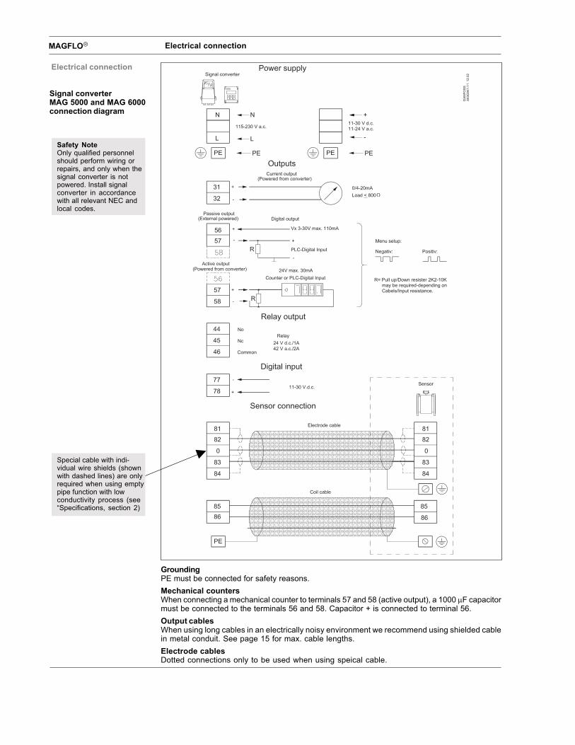
MAGFLO� Electrical connection
Electrical connection
Signal converterMAG 5000 and MAG 6000connection diagram
GroundingPE must be connected for safety reasons.Mechanical countersWhen connecting a mechanical counter to terminals 57 and 58 (active output), a 1000 �F capacitormust be connected to the terminals 56 and 58. Capacitor + is connected to terminal 56.Output cablesWhen using long cables in an electrically noisy environment we recommend using shielded cablein metal conduit. See page 15 for max. cable lengths.Electrode cablesDotted connections only to be used when using speical cable.
Special cable with indi-vidual wire shields (shownwith dashed lines) are onlyrequired when using emptypipe function with lowconductivity process (see“Specifications, section 2)
Safety NoteOnly qualified personnelshould perform wiring orrepairs, and only when thesignal converter is notpowered. Install signalconverter in accordancewith all relevant NEC andlocal codes.
MAGFLO� Project guidanceP
roje
ct g
uida
nce
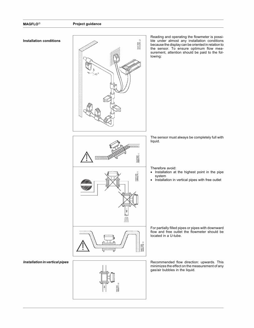
Installation conditionsReading and operating the flowmeter is possi-ble under almost any installation conditionsbecause the display can be oriented in relation tothe sensor. To ensure optimum flow mea-surement, attention should be paid to the fol-lowing:
The sensor must always be completely full withliquid.
Therefore avoid:� Installation at the highest point in the pipe
system� Installation in vertical pipes with free outlet
For partially filled pipes or pipes with downwardflow and free outlet the flowmeter should belocated in a U-tube.
Recommended flow direction: upwards. Thisminimizes the effect on the measurement of anygas/air bubbles in the liquid.
Installation in vertical pipes

MAGFLO Project guidance
Pro
ject
gui
danc
e
The sensor must be mounted as shown in theupper figure. Do not mount the sensor as shownin the lower figure. This will position the electrodesat the top where there is possibility for air bubblesand at the bottom where there is possibility formud, sludge, sand etc.If using empty pipe detection, the sensor can betilted 45�, as shown in the upper figure.
Recommended installation is in a vertical/inclinedpipe to minimize the wear and deposits in thesensor.
To achieve accurate flow measurement it is es-sential to have straight lengths of inlet and outletpipes and a certain distance between pumps andvalves.It is also important to centre the flowmeter inrelation to pipe flanges and gaskets.
The electrical potential of the liquid must alwaysbe equal to the electrical potential of the sensor.This can be achieved in different ways dependingon the application:A. Wire jumper between sensor and adjacent
flanges. (MAG 1100 and MAG 3100).B. Direct metallic contact between sensor and
fittings. (MAG 1100 FOOD).C. Built-in earthing electrodes. (MAG 3100 and
MAG 3100 W).D. Optional earthing/protection flanges/rings.
(MAG 1100 and MAG 3100).E. Optional graphite gaskets on MAG 1100.
(Standard for MAG 1100 High temperature).
Installation in horizontalpipes
Measuring abrasiveliquids and liquidscontaining particles
Inlet and outlet condi-tions
Potential equalization
MAGFLO� Project guidanceP
roje
ct g
uida
nce
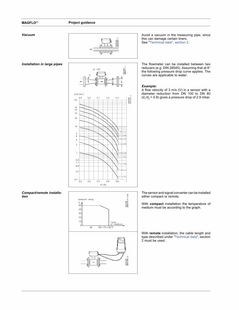
Avoid a vacuum in the measuring pipe, sincethis can damage certain liners.See "Technical data", section 2.
The flowmeter can be installed between tworeducers (e.g. DIN 28545). Assuming that at 8�the following pressure drop curve applies. Thecurves are applicable to water.
Example:A flow velocity of 3 m/s (V) in a sensor with adiameter reduction from DN 100 to DN 80(d1/d2 = 0.8) gives a pressure drop of 2.9 mbar.
The sensor and signal converter can be installedeither compact or remote.
With compact installation the temperature ofmedium must be according to the graph.
With remote installation, the cable length andtype described under "Technical data", section2 must be used.
Vacuum
Installation in large pipes
Compact/remote installa-tion
MAGFLO�co
nv.
Installation of signal converter
Installation of signalconverter
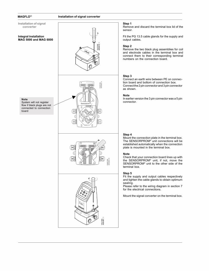
Integral installationMAG 5000 and MAG 6000
Step 1Remove and discard the terminal box lid of thesensor.
Fit the PG 13.5 cable glands for the supply andoutput cables.
Step 2Remove the two black plug assemblies for coiland electrode cables in the terminal box andconnect them to their corresponding terminalnumbers on the connection board.
Step 3Connect an earth wire between PE on connec-tion board and bottom of connection box.Connect the 2 pin connector and 3 pin connectoras shown.
NoteIn earlier version the 3 pin connector was a 5 pinconnector.
Step 4Mount the connection plate in the terminal box.The SENSORPROM® unit connections will beestablished automatically when the connectionplate is mounted in the terminal box.
NoteCheck that your connection board lines up withthe SENSORPROM® unit, if not, move theSENSORPROM® unit to the other side of theterminal box.
Step 5Fit the supply and output cables respectivelyand tighten the cable glands to obtain optimumsealing.Please refer to the wiring diagram in section 7for the electrical connections.
Mount the signal converter on the terminal box.
NoteSystem will not registerflow if black plugs are notconnected to connectionboard
MAGFLO�
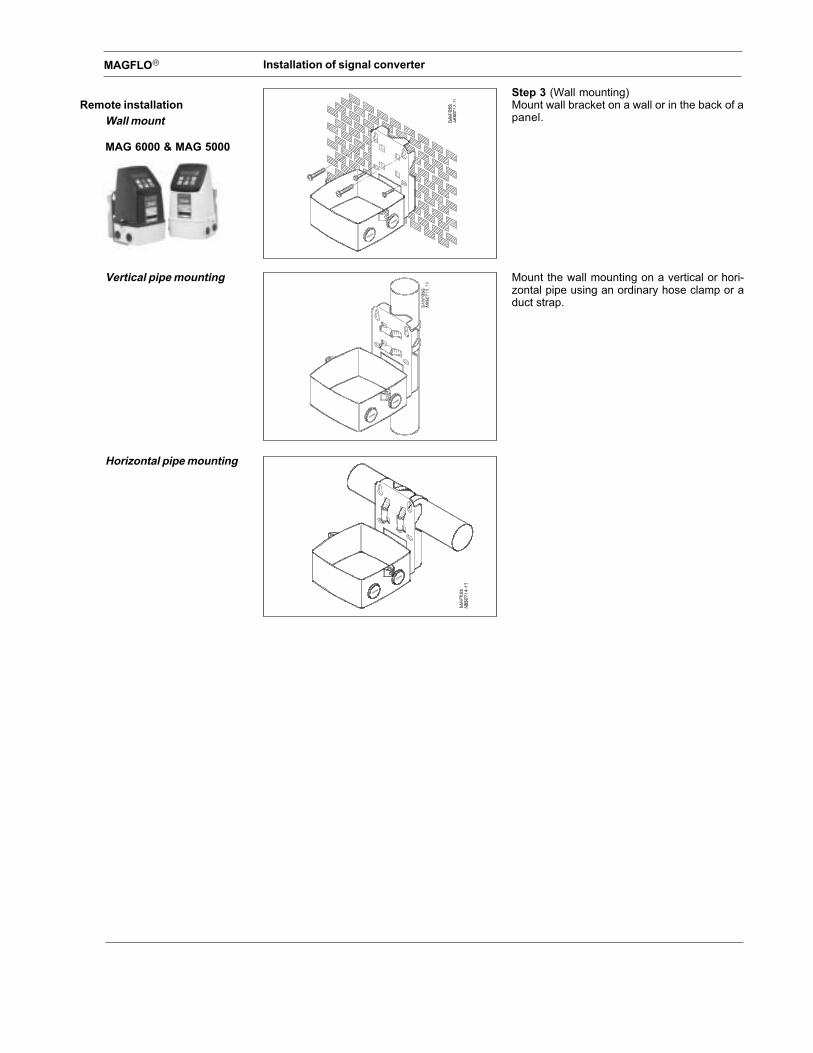
Remote installationWall mount
MAG 6000 & MAG 5000
Step 3 (Wall mounting)Mount wall bracket on a wall or in the back of apanel.
Mount the wall mounting on a vertical or hori-zontal pipe using an ordinary hose clamp or aduct strap.
Vertical pipe mounting
Horizontal pipe mounting
Installation of signal converter
MAGFLO�co
nv.
Installation of signal converter
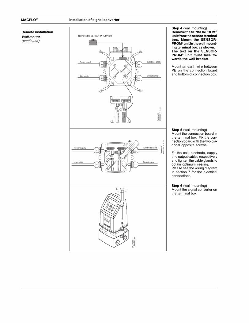
Remote installationWall mount(continued)
Step 4 (wall mounting)Remove the SENSORPROM®
unit from the sensor terminalbox. Mount the SENSOR-PROM® unit in the wall mount-ing terminal box as shown.The text on the SENSOR-PROM® unit must face to-wards the wall bracket.
Mount an earth wire betweenPE on the connection boardand bottom of connection box.
Step 5 (wall mounting)Mount the connection board inthe terminal box. Fix the con-nection board with the two dia-gonal opposite screws.
Fit the coil, electrode, supplyand output cables respectivelyand tighten the cable glands toobtain optimum sealing.Please see the wiring diagramin section 7 for the electricalconnections.
Step 6 (wall mounting)Mount the signal converter onthe terminal box.
Remove the SENSORPROM® unit