delamination detection and impact damage assessment of...
TRANSCRIPT

Int. J. Materials and Product Technology, Vol. 41, Nos. 1/2/3/4, 2011 5
Copyright © 2011 Inderscience Enterprises Ltd.
Delamination detection and impact damage assessment of GLARE by active thermography
Clemente Ibarra-Castanedo Computer Vision and Systems Laboratory, Department of Electrical and Computer Engineering, Université Laval, Quebec City G1K 7P4, Canada Fax: +1 (418) 656-3594 E-mail: [email protected]
Nicolas P. Avdelidis* Materials Science and Engineering Section, School of Chemical Engineering, National Technical University of Athens, Athens 157 80, Greece E-mail: [email protected] *Corresponding author
Ermanno G. Grinzato, Paolo G. Bison and Sergio Marinetti Istituto per le Tecnologie della Costruzione – Consiglio Nazionale delle Ricerche (ITC-CNR), Corso Stati Uniti, Padova 4-35127, Italy Fax: +39 (049) 829-5728 E-mail: [email protected] E-mail: [email protected] E-mail: [email protected]
Claudiu Cochior Plescanu, Abdelhakim Bendada and Xavier P. Maldague Computer Vision and Systems Laboratory, Department of Electrical and Computer Engineering, Université Laval, Quebec City G1K 7P4, Canada Fax: +1 (418) 656-3594 E-mail: [email protected] E-mail: [email protected] E-mail: [email protected]

6 C. Ibarra-Castanedo et al.
Abstract: GLAss REinforced (GLARE) is a fibre metal laminate (FML) consisting of alternating layers of thin aluminium and glass fibre reinforced prepregs, whose improved physical properties confer it an interesting advantage over aluminium and composite materials for a number of aerospace applications. On the other hand, contrary to monolithic structures, GLARE can suffer from internal damage either during fabrication or in-serve stages. Non-destructive testing and evaluation (NDT&E) of GLARE is still a challenge, especially considering that large structures are typically sought (e.g., aircraft fuselage). In this paper, we investigated the use of infrared thermography for the inspection of GLARE. The experimental results presented herein demonstrate that it is possible to detect delamination-type defects and to assess the impact severity on GLARE through active thermography techniques, specifically pulsed thermography and vibrothermography. C-scan ultrasonic testing was performed as well with the intention of providing supplementary results.
Keywords: active thermography; GLARE composites; fibre metal laminates; FMLs; pulsed thermography; PT; vibrothermography; VT; C-scan ultrasounds; impact damage; delaminations.
Reference to this paper should be made as follows: Ibarra-Castanedo, C., Avdelidis, N.P., Grinzato, E.G., Bison, P.G., Marinetti, S., Plescanu, C.C., Bendada, A. and Maldague, X.P. (2011) ‘Delamination detection and impact damage assessment of GLARE by active thermography’, Int. J. Materials and Product Technology, Vol. 41, Nos. 1/2/3/4, pp.5–16.
Biographical notes: Clemente Ibarra-Castanedo is a Postdoctoral Researcher in the Computer Vision and Systems Laboratory of Laval University in Quebec City, Canada. As a member of the Multipolar Infrared Vision Canada Chair (MiViM), he has contributed to more than 70 publications in the field of infrared thermography. His research interests are in signal processing and image analysis for the non-destructive characterisation of materials by active thermography. He is a member of the IEEE, ASME and SPIE.
Nicolas P. Avdelidis is a Principal Researcher for NDT&E and his scientific area of expertise is in the characterisation of materials and structures (i.e., buildings, composites, aerospace, etc.). His work has been principally concentrated on developing a thorough, internationally recognised, understanding of imaging characteristics mostly for thermal NDT, through modelling and experimental studies. He is a Licensed Instructor from ITC for Thermography and he is a member of the ISO WG15 for the new standard on thermography for buildings. He also acts as a Visiting Professor at Laval University in Canada, working closely with the Vision and Digital Systems Laboratory.
Ermanno G. Grinzato is a Senior Researcher at the National Research Council of Italy (CNR-ITC). He is active in applications of quantitative infrared thermography since 1980 and the leader of many heat and mass transfer international research projects. He is the author of more than 170 papers and the Coordinator of the working group ‘Thermography’ within NDT commission, belonging to the Standardisation Italian Body (UNI) and the Italian representative at ISO. He is also a member of the steering committee of the Quantitative Infrared Thermography (QIRT) Journal, the Thermosense Conference and the Advanced Infrared Technology and Applications (AITA) Workshop.

Delamination detection and impact damage assessment of GLARE 7
Paolo Bison received his Degree in Physical Sciences at the University of Padova on 1987; he is employed as a Researcher at the Italian National Research Council since 1988. His main areas of expertise are thermal non-destructive testing by IR thermography and measurement of thermal parameters by photothermal methods. His fields of application are aeronautics, power energy production, buildings and works of art.
Sergio Marinetti received his degree in Electronic Engineering and his PhD in Energetic from the University of Padua, Italy, in 1992 and 1996, respectively. Currently, he is a Researcher at the Institute of Building Technologies (Thermal NDT Branch) of the Italian National Research Council. His research fields are thermal non-destructive testing (T-NDT), thermal characterisation of materials and numerical simulation of thermal-fluidynamic processes.
Claudiu Cochior Plescanu is a Computer Engineering undergraduate student at Laval University, in Quebec City, Canada. His interests are in computer vision and microcontroller programming.
Abdelhakim Bendada received his PhD in 1995 at the Institut National Polytechnique de Lorraine in France. Prior to joining the National Research Council of Canada in 1997, he was affiliated to the Laboratoire d’Énergétique et de Mécanique Théorique et Apliquée in France. In 2005, he joined the Department of Electrical and Computer Engineering at Laval University in Canada as a Professor. His current scientific interests are centred on multipolar infrared vision applications and related image processing. He is the author or the co-author of more than 125 papers and various other contributions in these fields.
Xavier P. Maldague has been a Professor at the Electrical and Computing Engineering Department of Laval University since 1989. His research interests are in infrared thermography, non-destructive evaluation (NDE), vision and digital systems for industrial inspection. He authored or co-authored more than 130 papers, three books and one patent on these topics. He is active in several international organisations working in infrared NDE. He is a member of the CINDE, ASNT and IEEE, and co-editor of the Can. Journal of Electrical and Computing Engineering. In 2004, he was awarded the Canadian Research Chair MIVIM on Multipolar Infrared Vision (Infrarouge Multipolaire).
1 Introduction
GLAss REinforced (GLARE) is a hybrid material from the family of the fibre metal laminates (FMLs), which consist of alternating layers of thin metal (e.g., aluminium) sheets (0.3–0.5 mm thick) and glass fibre reinforced prepregs (0.25–0.5 mm thick). This configuration provides very good fatigue properties, good impact, damage tolerance and fire resistance characteristics. The main approach for developing GLARE composites includes the placement of layers from aluminium alloy(s) and the prepregs between them in a specific base. After this, the multilayer structure is placed in an autoclave for approximately two hours at a temperature of 120°C and 6 bar pressure. The aluminium layers have a maximum of 1.65 m of wideness, which poses a problem as far as the manufacturing of large structures of the aircraft is concerned (i.e., >2 m). To overcome

8 C. Ibarra-Castanedo et al.
this, the development of consecutive aluminium alloy layers (next to each other) leaving a very small gap in between them (~1 mm) has been used. This approach is also known as GLARE splicing method. Nonetheless, rapid delamination was observed, especially during the loading of such structures in more than 400 MPa. For this reason, the self-forming technique was developed. During this technique, due to the pressure that is applied at the doublers (i.e., placed aluminium alloy sheets) in the autoclave and because of the use of the adhesive for the preparation of the prepregs, the voids are filled from the material itself. The composite has now improved strength and the filled gaps are no longer the weak spots of the material.
The prerequisite for more competent and cost effective aircraft has led to the evolution of innovative testing and evaluation procedures. Non-destructive testing and evaluation (NDT&E) techniques for assessing the integrity of an aircraft structure are essential to both reduce manufacturing costs and out of service time of aircraft due to maintenance. In literature, one can find C-scan ultrasonic inspection (Blitz and Simpson, 1996) on composite structures from GLARE. Furthermore, X-rays radiography (Alaknanda et al., 2006) has been used in the inspection of GLARE in specific situations, such as preliminary detection of cracks in the aluminium part of the material. Eddy current testing (Cawley, 1990) has also been applied, providing good results for detection on the surface and near surface defects. The main limitation of this approach is detecting defects at the greater depths within the material. Furthermore, infrared thermography (Meola et al., 2004) has also found use in the inspection of joints from GLARE composites in both online process monitoring and non-destructive evaluation of final products. Nowadays, active thermography thermal NDT&E is commonly used for assessing aircraft composites as explained next.
2 Active thermography
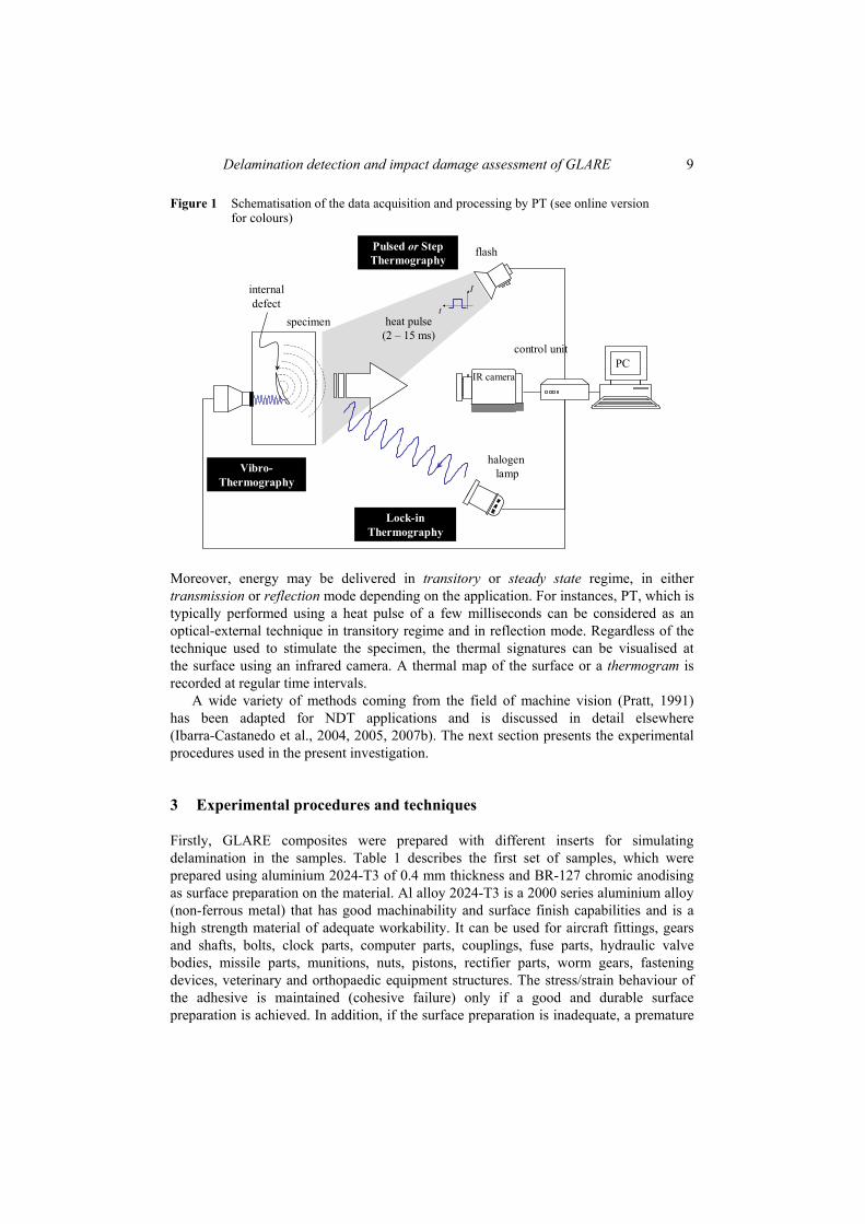
Infrared thermography is an NDT&E technique allowing fast inspection of large surfaces (Maldague, 2001). There are different active techniques depending on the stimulation source (Ibarra-Castanedo et al., 2007a): pulsed thermography (PT), step thermography (ST), lock-in thermography (LT) and vibrothermography (VT), to name the most popular. Data acquisition is carried out as depicted in Figure 1.
The specimen is stimulated with an energy source, which can be of many types, such as optical, mechanical or electromagnetic. Optical energy is normally delivered externally, i.e., heat is produced at the surface of the specimen from where it travels trough the specimen to the subsurface anomaly (defect) and back to the surface. Mechanical energy, on the other hand, can be considered as an internal way of stimulation, since heat is generated at the defect interface and then travels to the surface. Inductive excitation can be applied internally to electro-conductive-materials, generating eddy currents at a specific depth (determined by the frequency of the excitation), heating up the specimen and the eventual internal defects. Surface or subsurface defects produce variations on the eddy current patterns, changing the temperature distribution. As with the previous excitation forms, these temperature variations can be detected on the surface with an infrared camera.
Delamination detection and impact damage assessment of GLARE 9
Figure 1 Schematisation of the data acquisition and processing by PT (see online version for colours)
I
tspecimen heat pulse
(2 – 15 ms)
internal defect
flash
PCcontrol unit
halogen lamp
Pulsed or Step Thermography
Lock-in Thermography
IR camera
Vibro-Thermography
Moreover, energy may be delivered in transitory or steady state regime, in either transmission or reflection mode depending on the application. For instances, PT, which is typically performed using a heat pulse of a few milliseconds can be considered as an optical-external technique in transitory regime and in reflection mode. Regardless of the technique used to stimulate the specimen, the thermal signatures can be visualised at the surface using an infrared camera. A thermal map of the surface or a thermogram is recorded at regular time intervals.
A wide variety of methods coming from the field of machine vision (Pratt, 1991) has been adapted for NDT applications and is discussed in detail elsewhere (Ibarra-Castanedo et al., 2004, 2005, 2007b). The next section presents the experimental procedures used in the present investigation.
3 Experimental procedures and techniques
Firstly, GLARE composites were prepared with different inserts for simulating delamination in the samples. Table 1 describes the first set of samples, which were prepared using aluminium 2024-T3 of 0.4 mm thickness and BR-127 chromic anodising as surface preparation on the material. Al alloy 2024-T3 is a 2000 series aluminium alloy (non-ferrous metal) that has good machinability and surface finish capabilities and is a high strength material of adequate workability. It can be used for aircraft fittings, gears and shafts, bolts, clock parts, computer parts, couplings, fuse parts, hydraulic valve bodies, missile parts, munitions, nuts, pistons, rectifier parts, worm gears, fastening devices, veterinary and orthopaedic equipment structures. The stress/strain behaviour of the adhesive is maintained (cohesive failure) only if a good and durable surface preparation is achieved. In addition, if the surface preparation is inadequate, a premature

10 C. Ibarra-Castanedo et al.
failure will occur. A reliable non-tank and environmental friendly treatment is essential. The material for the treatment is solvent base anti-corrosion primer Cytec-Fiberite BR-127. The defects were either from Teflon® (denoted DTx, where ‘T’ stands for Teflon® and ‘x’ is the sample number) or polyamide (denoted DPx, where ‘P’ stands for polyamide and ‘x’ is the sample number), the dimensions and specifications of all investigated samples can be seen in the schematic of Figure 2(a). Table 1 Description of GLARE specimens (150 × 50 mm2)
Sample GLARE type Composite orientation
DT1 G.e-g/w-2/1-0.4 E-glass MMR-002/w DP2 G.e-g/w-2/1-0.4 E-glass MMR-002/w DT3 G.bor-2/1-0.4 Boron 5521/un DP4 G.bor-2/1-0.4 Boron 5521/un DT5 G.e-g/w-3/2-0.4 E-glass MM-002/w DP6 G.e-g/w-3/2-0.4 E-glass MMR-002/w DT7 G.bor-3/2-0.4 Boron 5521/un-un DP8 G.bor-3/2-0.4 Boron 5521/un-un
Lay-up
DT1 Al/FM-73/e-glass/FM-73/Al DP2 Al/FM-73/e-glass/FM-73/Al DT3 Al/FM-73/boron/FM-73/Al DP4 Al/FM-73/boron/FM-73/Al DT5 Al/FM-73/e-glass/FM-73/Al/FM-73/e-glass/FM-73/Al DP6 Al/FM-73/e-glass/FM-73/Al/FM-73/e-glass/FM-73/Al DT7 Al/FM-73/boron/FM-73/Al/FM-73/boron/FM-73/Al DP8 Al/FM-73/boron/FM-73/Al/FM-73/boron/FM-73/Al
Figure 2 Schematic of investigated samples containing inserts, (a) DT and DP type specimens (b) specimen GLARE013
5 cm
2 cm
4 cm
3.5 cm
3.5 cm
2 cm
15 mm
10 mm
5 mm
2.5 mm
15.2cm
0°90°0°
15.2 cm
1.2 cm
1.0 cm
0.5 cm
FM94S2Al
Release film1 ply = 45 μm
Release film2 plies = 95 μm
Kapton (1 ply + Frekote) = 86 μm
Al shim (1 ply + Frekote) = 91 μm
(a) (b)

Delamination detection and impact damage assessment of GLARE 11
Secondly, a GLARE specimen (Al/0°/90°/0°/Al/0°/90°/0°/Al/0°/90°/0°/Al, using unidirectional glass-fibre epoxy layer FM® 94) was fabricated with simulated delaminations of four kinds: one-ply film release, two-plies film release, Kapton®/Frekote® inserts and aluminium shim/Frekote® inserts. FM® 94 adhesive was used given its elongation, toughness and shear strength properties, which are well suited for composite and metal bonding. The specifications for this plate are shown in Figure 2(b). Table 2 Description of GLARE type composites
Specimen Impact energy (J) Lay-up
Glare001 2 Al/FM® 94/s-glass/FM® 94/Al/FM® 94/s-glass/FM® 94/Al Glare002 4 Al/FM® 94/s-glass/FM® 94/Al/FM® 94/s-glass/FM® 94/Al l Glare003 2 Al/FM® 94/s-glass/FM® 94/Al Glare004 4 Al/FM® 94/s-glass/FM® 94/Al Glare005 2 Al/FM® 94/s-glass/FM® 94/Al Glare006 8 Al/FM® 94/s-glass/FM® 94/Al Glare007 8 Al/FM® 94/s-glass/FM® 94/Al/FM® 94/s-glass/FM® 94/Al Glare008 8 Al/FM® 94/s-glass/FM® 94/Al Glare009 8 Al/FM® 94/s-glass/FM® 94/Al/FM® 94/s-glass/FM®94/Al Glare010 4 Al/FM® 94/s-glass/FM® 94/Al Glare011 4 Al/FM® 94/s-glass/FM® 94/Al/FM® 94/s-glass/FM® 94/Al Glare012 2 Al/FM® 94/s-glass/FM® 94/Al/FM® 94/s-glass/FM® 94/Al
And lastly, 12 GLARE composites, using s-glass instead of e-glass, were prepared for impact damage testing; six with Al/FM® 94/s-glass/FM® 94/Al and the other six with Al/FM® 94/s-glass/FM® 94/Al/FM® 94/s-glass/FM® 94/Al, see Table 2. In the instance of the impact damage testing (Avdelidis et al., 2004a), a falling weight impact tester was used. A lead filled tube with a standard hemispherical 8 mm diametre steel ball was used as the impacter. A sliding plate at the base of the guiding tower allows the impacter tube to be caught after impact to prevent secondary impact of the sample. The impact energy was calculated using the standard equation: E = mgh, where: m is the mass of the impacter, g is the acceleration due to gravity (9.81 m/s) and h is the height from which the weigh was dropped. The following impact energies were calculated: 2 J, 4 J and 8 J, as indicated in Table 2.
In the investigation of the inserts, acquisition was carried out using either a Santa Barbara Focal Plane SBF125 camera (14 bits, InSb 320 × 256 FPA, 3–5 μm, nitrogen-cooled) or a ThermaCAMTM Phoenix® from FLIR Systems (14 bits, InSb 640 × 512 FPA, 3–5 μm, Stirling closed cycle cooler). Two high power flashes (Balcar FX 60), providing 6.4 KJ for 2–10 ms each, were used as heating sources. For the case of VT inspection, a transducer working at 20 kHz was used as an ultrasound source. Thermographic data was analysed with a PC (Pentium 4, 2 GB RAM) using MATLAB® language from The MathWorks, Inc. In the investigation of the impact damaged samples, a pulsed thermographic system (Echotherm from Thermal Wave Imaging) employing a medium wave (3 to 5 μm) infrared camera (Phoenix) was used for the imaging and analysis of the panels. Echotherm, a portable state-of-the-art NDT&E system, has an attached integrated flash heating system (giving ~10 KJ for variable duration of the flash
12 C. Ibarra-Castanedo et al.
heating – up to 25 ms). The Phoenix mid-wave infrared camera (also attached to the system) uses a cooled InSb detector with a maximum frame rate of 60 Hz and a focal plane array pixel format of 320 × 256.
Furthermore, C-scan ultrasonic immersion testing (OMNIscan MX by Olympus NDT) was also used. It is not the purpose of this study to provide a detailed description of C-scan ultrasound, which is an NDT technique well-described in the literature. Results presented herein are intended to provide supplementary information about the defects.
4 Results and discussion
In the investigation of composites with active thermographic approaches, since the thermal diffusivity mainly affects the time of maximum thermal contrast, the clearest images (high thermal contrast between defect and sound area) are acquired at relatively long periods during the cooling down thermal transient process.
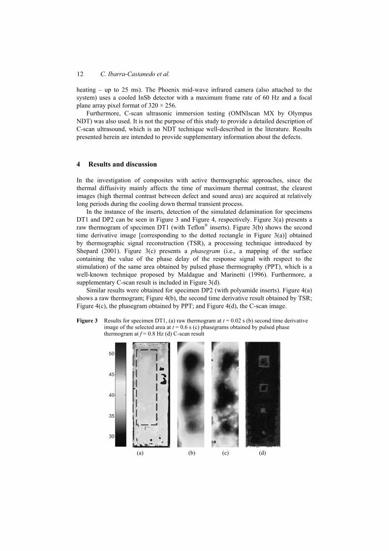
In the instance of the inserts, detection of the simulated delamination for specimens DT1 and DP2 can be seen in Figure 3 and Figure 4, respectively. Figure 3(a) presents a raw thermogram of specimen DT1 (with Teflon® inserts). Figure 3(b) shows the second time derivative image [corresponding to the dotted rectangle in Figure 3(a)] obtained by thermographic signal reconstruction (TSR), a processing technique introduced by Shepard (2001). Figure 3(c) presents a phasegram (i.e., a mapping of the surface containing the value of the phase delay of the response signal with respect to the stimulation) of the same area obtained by pulsed phase thermography (PPT), which is a well-known technique proposed by Maldague and Marinetti (1996). Furthermore, a supplementary C-scan result is included in Figure 3(d).
Similar results were obtained for specimen DP2 (with polyamide inserts). Figure 4(a) shows a raw thermogram; Figure 4(b), the second time derivative result obtained by TSR; Figure 4(c), the phasegram obtained by PPT; and Figure 4(d), the C-scan image.
Figure 3 Results for specimen DT1, (a) raw thermogram at t = 0.02 s (b) second time derivative image of the selected area at t = 0.6 s (c) phasegrams obtained by pulsed phase thermogram at f = 0.8 Hz (d) C-scan result
(a) (b) (c) (d)

Delamination detection and impact damage assessment of GLARE 13
Figure 4 Results for specimen DP2, (a) raw thermogram at t = 0.02 s (b) second time derivative image of the selected area at t = 0.06 s (c) phasegrams obtained by pulsed phase thermogram at f = 1 Hz (d) C-scan result
(a) (b) (c) (d)
From these results, it is possible to detect the three largest inserts by PT. Defect contrast is better for polyamide inclusions (specimen DP2, Figure 4) than for Teflon® inserts (specimen DT1, Figure 3). No VT results are available at this point although the C-scan images for both specimens showing all defects suggest that future VT tests will provide useful results.
In the case of specimen GLARE013, all defects can be seen by PT [Figure 5(a)] with data processed by TSR using the first time derivative as described by Shepard (2001), and most of them can be detected by VT [Figure 5(b)]. However, it is more difficult to differentiate between materials from the VT results than by PT. Aluminium inserts in particular have a distinctive signature with inverted sign as can be seen. An additional defect can be seen in the first column of defects (one-ply film release). This defect was not included on the specimen specifications from the manufacturer. C-scan results [Figure 5(c)] confirm the existence of this defect. Another interesting observation is that the PT result in Figure 5(a) shows a surface paint scratch (indicated by a dotted circle), which is barely detectable by VT result [Figure 5(b)] and undetectable by C-scan ultrasounds [Figure 5(c)]. The reason for this is that optical excitation is used in PT, delivering the energy (light) to the surface where heat is produced and then travels though the specimen. This type of energy stimulation of heating the whole surface (unevenly) and to be affected by the surface conditions of the specimen, a scratch in the surface in this case. On the other hand, VT uses ultrasound waves, which travels through the specimen after being applied in a specific area. Heat is produced in the interface of the defective areas and the specimen material from where it travels to the surface. This type of stimulation is a more effective way of heating, since only defective areas are heated and not the whole surface of the specimen as in PT. The paint scratch in the surface is visible as well [although the signature is weaker than in PT, see Figure 5(d)] given that the scratch has dissimilar thermal properties. In the case of the C-scan result, the scratch is seen at all since it does not affect the ultrasound signature at this particular ultrasound frequency (i.e., 15 MHz).

14 C. Ibarra-Castanedo et al.
Figure 5 (a) first derivative image at t = 0.6 s (b) VT result (c) C-scan ultrasounds (15 MHz) (see online version for colours)
(a) (b) (c)
In the case of the assessment of the impact-damaged samples, it was possible to view the impact damage on the surface, especially in the case of the thinner composite panels such as specimen GLARE006 (Figure 6, top). Furthermore, even in the case of the thicker samples as specimen GLARE007 (Figure 6, bottom), the defected areas, created by the impact damage testing, could be picked up by PT as can be seen in Figure 6(a). Processing results by PPT (Maldague and Marinetti, 1996) improve defect contrast and provides an indication about the extent of the internal damage. In accordance with the phase probing properties (Busse et al., 1992), the phasegrams at 1 Hz [Figure 6(b)] provide information about deeper features than the phasegrams at 0.15 Hz. It can be observed from these results that the extent of damage is greater for the case of a thin plate subjected to a high energy impact (8 J) than for a thick plate subjected to a lower impact energy (4 J), as expected.
Figure 6 Results for specimens GLARE006 (top) and GLARE007 (bottom) after impact damage testing using 8 J and 4 J, respectively, (a) thermogram and the corresponding phasegrams of the cropped portion obtained by PPT (b) at f = 1 Hz (c) at f = 0.15 Hz (see online version for colours)
(a) (b) (c)
Ultrasonic A-B-C-scan results for specimen GLARE006 are shown in Figure 7 for three ultrasound frequencies, as indicated. From these results, it can be seen that is difficult to

Delamination detection and impact damage assessment of GLARE 15
get a signal from the second aluminium layer since glass fibres reflect back ultrasound waves and hinder the visibility of the subsequent aluminium layers.
Figure 7 Ultrasonic testing results for specimen GLARE006, (a) 5 MHz (b) 10 MHz (c) 15 MHz
(a) (b) (c)
5 Conclusions
The main objective of this work was to employ active thermography approaches such as PT and VT in order to detect simulated delamination (inserts), as well as impact damage on GLARE composite panels. Both approaches were mostly used in qualitative terms, i.e., defect detection, see for instance the study by Avdelidis et al. (2004b). The acquisition of the thermograms was completed taking into consideration the thermal characteristics of the composites under investigation, as well as the defect type (i.e., impact damage or delamination). Processed results showed that it is possible to differentiate between dissimilar materials in case of delamination-like inserts and to provide an indication of the damage severity from impacted specimens. It is therefore concluded that thermography could be used in the rapid investigation of GLARE composites, producing interpretable results.
An important difference between active thermography techniques should be pointed out. Data acquisition by PT is very straightforward; the specimen needs no preparation other than surface painting to increase its emissivity. Advance data processing is required, however, since the infrared signature is affected by non-uniform heating, environmental reflections and emissivity variations at the surface. On the other hand, VT is a more effective way of heating, since only defective areas are heated and not the whole surface of the specimen as in PT considerably reducing surface artefacts. Nevertheless, VT has the inconvenience of requiring a physical contact between the ultrasound transducer and the specimen and of being affected by several experimental parameters (e.g., the pressure applied between the horn and the specimen, the contact area between the horn and the specimen and the duration of the stimulation have a great impact on the thermal response). In addition, VT only provided useful results for one of the investigated cases, i.e., sample GLARE013 with delamination-like inserts of four different types. Further investigation is required for the case of impacted GLARE samples and to confirm VT’s availability for detecting delaminations.

16 C. Ibarra-Castanedo et al.
Acknowledgements
Acknowledgements are attributed to the Hellenic Aerospace Industry in Greece and the National Research Council of Canada Institute for Aerospace Research for the preparation of specific samples within this work. The support of the Natural Sciences and Engineering Research Council of Canada is also acknowledged.
References Alaknanda, Anand, R.S. and Kumar, P. (2006) ‘Flaw detection in radiographic weld images using
morphological approach’, J. NDT&E International, Vol. 39, No. 1, pp.29–332. Avdelidis, N.P., Almond, D.P., Dobbinson, A., Hawtin, B.C., Ibarra-Castanedo, C. and
Maldague, X. (2004a) ‘Aircraft composites assessment by means of transient thermal NDT’, Invited review paper, J. Progress in Aerospace Sciences, Vol. 40, pp.143–162.
Avdelidis, N.P., Ibarra-Castanedo, C., Maldague, X., Marioli-Riga, Z.P. and Almond, D.P. (2004b) ‘A thermographic comparison study for the assessment of composite patches’, J. Infrared Phys. Technol., Vol. 45, pp.291–299.
Blitz, J. and Simpson, G. (1996) Ultrasonic Methods of Non-destructive Testing, Chapman & Hall, London, UK.
Busse, G., Wu, D. and Karpen, W. (1992) ‘Thermal wave imaging with phase sensitive modulated thermography’, J. Appl. Phys., Vol. 71, No. 8, pp.3962–3965.
Cawley, P. (1990) ‘Low frequency NDT techniques for the detection of disbonds and delamination’, British Journal of NDT, Vol. 32, No. 9, pp.454–460.
Ibarra-Castanedo, C., Bendada, A. and Maldague, X. (2005) ‘Image and signal processing techniques in pulsed thermography’, GESTS Int’l Trans. Computer Science and Engr., Vol. 22, No. 1, pp.89–100.
Ibarra-Castanedo, C., Bendada, A. and Maldague, X. (2007a) ‘Chapter 16: active infrared thermography techniques for the nondestructive testing of materials’, in C.H. Chen (Ed.): Ultrasonic and Advanced Methods for Nondestructive Testing and Material Characterization, World Scientific Publishing.
Ibarra-Castanedo, C., Bendada, A. and Maldague, X. (2007b) ‘Thermographic image processing for NDT’, Specially invited paper, Proc. IV Pan American Conference in END, Buenos Aires, Argentina, 22–26 October, available at http://www.ndt.net/article/panndt2007/papers/55.pdf.
Ibarra-Castanedo, C., González, D., Klein, M., Pilla, M., Vallerand, S. and Maldague, X. (2004) ‘Infrared image processing and data analysis’, J. Infrared Phys. Technol., Vol. 46, Nos. 1–2, pp.75–83.
Maldague, X.P. and Marinetti, S. (1996) ‘Pulse phase infrared thermography’, J. Appl. Phys., Vol. 79, No. 5, pp.2694–2698.
Maldague, X.P.V. (2001) Theory and Practice of Infrared Technology for NonDestructive Testing, John Wiley-Interscience.
Meola, C., Carlomagno, G.M., Squillace, A. and Giorleo, G. (2004) ‘The use of infrared thermography for nondestructive evaluation of joints’, J. Infrared Phys. Technol., Vol. 46, pp.93–99.
Pratt, W.K. (1991) Digital Image Processing, Wiley, New York. Shepard, S.M. (2001) ‘Advances in pulsed thermography’, in Andres E. Rozlosnik and
Ralph B. Dinwiddie (Eds.): Proc. SPIE, Thermosense XXIII, Vol. 4360, pp.511–515.