delanoe anton - archives.polytechnice.fr ·...
TRANSCRIPT

VisionergyTM Project Report
Delanoe Anton - Mouton Jean-Gaël - Zanzouri Steeve
June 13, 2008

We first want to thank our tutor Mr. Millon.We would like to thank Mr Braquet for his precious help, and especiallyfor permanently motivating all the team during those six months.We will also thank Mr. Staraj, Mr Arnould, and Mr. Demartini fortheir technical advice and for their disponibility.We won’t forget to thank all the "Challenge Jeunes Pousses" advisorsfor all the things they taught us.Finally, we would like to thank the Sophia Team for the material assistancethey provided us.
1

Introduction
The main purpose of this paper is to present our second year project realizedduring the last six month: VisionergyTM, which participated to this year“Challenge Jeunes Pousses” contest up to the final so far. Nowadays, we aremore and more concerned with environmental issues and we can see a lot ofnew technologies and products, so called “clean”, emerging on the market.We decided to embrace this concept and that is why this project interestedus at first.In a first part, we will give a brief presentation of our team and of ourproject scope statement. Then, we will try to propose a clear explanation ofthe technical principles we used to create our prototype before concludingby explaining concretly what the CJP is and what we have learnt in thisadventure.
2

Contents
Introduction 2
1 Team presentation 5
2 Specifications 62.1 VisionergyTM Belt - The theory . . . . . . . . . . . . . . . . . 6
2.1.1 Description . . . . . . . . . . . . . . . . . . . . . . . . 62.1.2 Energy recovery system . . . . . . . . . . . . . . . . . 72.1.3 The lighting system . . . . . . . . . . . . . . . . . . . . 82.1.4 Power circuit management . . . . . . . . . . . . . . . . 9
3 Project development 103.1 Technical part . . . . . . . . . . . . . . . . . . . . . . . . . . . 10
3.1.1 Energy recovery . . . . . . . . . . . . . . . . . . . . . . 113.1.2 Management power circuit . . . . . . . . . . . . . . . . 183.1.3 Lightning system . . . . . . . . . . . . . . . . . . . . . 24
4 Challenge Jeunes Pousses 284.1 Presentation . . . . . . . . . . . . . . . . . . . . . . . . . . . . 284.2 Professional experience . . . . . . . . . . . . . . . . . . . . . . 294.3 Future of VisionergyTM . . . . . . . . . . . . . . . . . . . . . . 31
A Previsionnal Planning 34
B Flyer 35
C Electromagnetic calculations 36
D Mechanical model calculations 37
3

List of Figures
1.1 Organigram of the VisionergyTM Team . . . . . . . . . . . . . 5
2.1 Comparative of three different technics of energy recovery ona runner . . . . . . . . . . . . . . . . . . . . . . . . . . . . . . 7
3.1 Splitted technical part . . . . . . . . . . . . . . . . . . . . . . 103.2 Optimized linear dynamo . . . . . . . . . . . . . . . . . . . . . 113.3 Linear dyamo best results . . . . . . . . . . . . . . . . . . . . 123.4 Results for a mouvement frequency close to that of a runner . 123.5 Magnetic induction . . . . . . . . . . . . . . . . . . . . . . . . 133.6 Mechanical model of our system . . . . . . . . . . . . . . . . . 153.7 Test result of the optimized system . . . . . . . . . . . . . . . 173.8 Alternative signal to positive signal . . . . . . . . . . . . . . . 183.9 First rectifier . . . . . . . . . . . . . . . . . . . . . . . . . . . 193.10 First rectifier (Test of the first rectifier) . . . . . . . . . . . . . 193.11 Second rectifier . . . . . . . . . . . . . . . . . . . . . . . . . . 203.12 Test of the second rectifier (blue : Ve and clear blue : Vs) . . . 213.13 Switch circuit . . . . . . . . . . . . . . . . . . . . . . . . . . . 223.14 Final circuit . . . . . . . . . . . . . . . . . . . . . . . . . . . . 233.15 Amount of Energy released when an electron drops to valence
band and recombination occurs . . . . . . . . . . . . . . . . . 243.16 Luminous flux . . . . . . . . . . . . . . . . . . . . . . . . . . . 253.17 LED (the arrow is pointing the reflector) . . . . . . . . . . . . 253.18 Light angle of a LED . . . . . . . . . . . . . . . . . . . . . . . 26
4.1 The VisionergyTM Team (from left to right: JG MOUTON, C.BRESIN, A. DELANOE, S. ZANZOURI) . . . . . . . . . . . 29
4.2 First previsional planning . . . . . . . . . . . . . . . . . . . . 304.3 Second previsional planning . . . . . . . . . . . . . . . . . . . 31
4

Chapter 1
Team presentation
Our team consists in a multi-school association of two different specializa-tions: electronics engineering (EPUNSA), as well as business and manage-ment (CERAM). The electronics part of the team is responsible for designingand building the belt, with various tasks such as designing the energy recov-ery system, as well as the power management circuit, and the business partof the team is here to help us realizing our business plan and commercialapproach in the CJP contest.Following is the organization tree of the team:
Figure 1.1: Organigram of the VisionergyTM Team
5

Chapter 2
Specifications
2.1 VisionergyTM Belt - The theory
2.1.1 Description
VisionergyTM is a signalisation running belt which will make a runner morevisible to drivers without any battery. We really wished to embrace the con-cept of sustainable development thus our belt is entirely equipped with cleantecnhologies. To achieve our goal, we created an innovative power systemwhich will be able to feed the whole belt with electricity. We will have tobuild the system, and to make any necessary tests to make sure it has thecapacity to be commercialized. The main advantage of our project is its ex-treme ease of use. In fact, a runner just has to wear it and when he willstart running, he will be visible from everybody, which will greatly increasehis security. Furthermore, he will never have to change any battery, and willnever be worried about a power breakdown for the simple reason that thereis not any kind of battery in our system. VisionergyTMTM is a sport securityarticle hence it will have to be perfectly optimized, and then has to combinedifferent qualities like robustness ,toughness and design. As a consequence,here are our main requirements for our signalisation belt:
• Clean and innovative technology
• No battery
• Visibility
• Respect of sportive performance
6

Now we will detail these different requirements.
2.1.2 Energy recovery system
This system is the heart of our project. Indeed, if we do not have any electricalpower, it will be impossible for us to light up anything on the belt. We finallycame to three possible technologies before choosing the best way to producethe necessary power:
• Thermal energy recovery
• Piezo-electric materials
• Mechanical energy recovery
We now have to compare these three possible options. We spent a long timeon this part of the project as we wanted to take the best decision as wecould not afford to make a mistake because the whole project is based onthat technology. Thus, we classified our three identified options according tothree criterions which are: cost, ease of development and ease of use. We thenestablished those graphics:
Figure 2.1: Comparative of three different technics of energy recovery on arunner
7

We quickly decided to drop piezo-electric materials because they are reallyexpensive although it is an ingenious technology perfectly adapted to ourproject technologically speaking. Indeed, piezoelectricity is the ability of somematerials (notably crystals and some ceramics) to generate an electrical po-tential in response to mechanical stress. The development of a system usingpiezoelectricity is not possible with our skills and will be a loss of time be-cause even though piezo-electric materials are very easy to use (you just haveto wear them), their price is crippling.About thermal energy recovery, we though that it was a very interestingtechnology because it is a good compromise according to our requirements.Moreover we know that is possible to obtain a between 2,4W and 2,8W1 onlyby exploiting the head temperature rising while running.
Moreover, the development was possible with our capacities, and the costswere moderate but in the end, we chose the mechanical energy recovery asour main power source for differents reasons.
Indeed, this concept seduced us very quickly as our study concluded thatthe conversion of a human body movements into electricity was a perfectlyadapted power source to produce a power of only a couple of Watts. Aftersome tests, we concluded that we could obtain between 5W and 8,3W. Itis thus this technology which is able to supply us the greatest possibility oflighting of our LEDs. Furthermore, we had to inform ourselves about me-chanical energy recovery methods, and it seemed that with a linear dynamosystem, it would be completely possible. This is a second very good point forthis technology in that its development is quite simple and it is also a lowcost technology.We thus chose to use a mechanical energy recovery system for ourbelt. We will present the details of this system later in the technical part ofthis report.
2.1.3 The lighting system
The choice of an adapted lighting system is a vital part of our projet in thatit will condition the future performances of our belt. Requirements:
• Visibility superior to 70m in black night
• Low consumption
• Cheap1Exemple of consommation: radio Fm 30mW, Walkman 60 mW et pocket light 4W
8
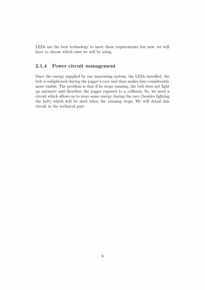
LEDs are the best technology to meet these requirements but now, we willhave to choose which ones we will be using.
2.1.4 Power circuit management
Once the energy supplied by our innovating system, the LEDs installed, thebelt is enlightened during the jogger’s race and then makes him considerablymore visible. The problem is that if he stops running, the belt does not lightup anymore and therefore the jogger exposed to a collision. So, we need acircuit which allows us to store some energy during the race (besides lightingthe belt) which will be used when the running stops. We will detail thiscircuit in the technical part.
9

Chapter 3
Project development
3.1 Technical part
Here we are going to talk about details of the technologies we used to arriveto a fonctionnal prototype, like the one presented during the CJP contest.Technical parts can be divided into three parts as it is shown below:
Figure 3.1: Splitted technical part
10

3.1.1 Energy recovery
Electromagnetic aspect of the energy recovery system
As VisionergyTM uses a linear dynamo system to produce its energy, our firstappearing difficulty was to understand properly the functioning of electro-magnetism and electromagnetic induction in order to build our first proto-type, and also to optimize it in terms of power output and size in the future.First of all, we had to interest ourselves to the core of our system: the mag-net. Considering that we had severe restrictions in terms of size for our globalsystem, we needed a magnet as strong as possible but which is small. Thatwas why we chose to use different ’Rare earth’ (lanthanoid) supermagnetsfrom various dimensions and power. Considering that we had a coil of 1556turns wrapped around our plastic tube at our disposal, we made differenttests to find the magnet giving the best results and which size did not ex-ceed the diameter of the tube. This magnet had a diameter of 1.75 cm anda magnetic power of 500 mT.
Figure 3.2: Optimized linear dynamo
11

Test of the linear dynamo
We tested our system with an oscilloscope and we obtain those graphicswhich completly satisftied us:
Figure 3.3: Linear dyamo best results
Figure 3.4: Results for a mouvement frequency close to that of a runner
These tests were really satisfying as the peak-to-peak voltage output wasmore than enough to light up our LEDs network and thus, we had a proofof the feasability of our project.
12

Let’s now explain what really happens in the system.The first thing to re-member is that the intensity of a magnetic flux φ received by a closed sur-face ~S is equal to the number of magnetic induction field ~B force lines goingthrough this surface. Thus, it corresponds to the scalar product of these twovectors, respecting the following equation:
The next figure gives a good exemple of what was just stated, we can see theforce lines going through the surface of the coil.
Figure 3.5: Magnetic induction
Now, we can interest ourserlves to how this magnetic flux will help us pro-duce electrical energy. When the magnet is going back and forth into the coil,the perceived flux is varying a lot from the coil surface point of view, fromB = max = B.S to B=0 (cos θ =1 to cos θ =0). Therefore, we can apply, inour case, the famous law of Faraday stating that when a circuit is subject toa magnetic flux φ coming from a varying magnetic field ~B, it is also subjectto an electromotive force with respect to the following equation:
This electromotive force will therefore create a difference of potential thatwill make a current flow in any charge we can attach to the system, such asLEDs for example.
13
Having these tools at our disposal, we began to investigate how to reducethe size of our system (magnet + diameter of the tube) while keeping thesame performances. Our most powerful small magnet had a magnetic powerof 130 mT with a diameter of 1cm and after some calculations (see theappendix), we determined that we needed a coil of 18305 turns, which wascompletely unrealistic for such an application and we chose to put aside thisaspect for a while.Only recently we thought again about reducing the size of our system whenwe found a supermagnet with a diameter of 1cm and a magnetic power of270 mT, hence reducing the number of turns to 8807, which is more re-alistic1. We now have better chances to be able to minimize the size of thesystem in the future.
Mechanical aspect of the energy recovery system
Having explained the electromagnetic aspect of our energy recovery system,we will now explain its mechanical aspect. Indeed, as our system is meant tobe put on a jogger belt, it is obviously meant to convert a mechanical energyfrom a race movement to a useful electrical energy, thus it is an oscillatorysystem. As said earlier, the mechanical impulse of a jogger starting to runwas not powerful enough to start an oscillation of the magnet. We thereforehad to modify the system. The idea was to make the resonance frequency ofthe whole system as close as possible from the average movement frequencyof a runner in order to almost trigger a resonance while running.We first thought about attaching the magnet to two springs, each of themattached to the bottom and up of the tube, but rather than facilitating theoscillations, it would have put the system in an equilibrium state after quitea short time. That is why we decided to attach the bottom spring on themagnet only to use it as a “braking” system stocking potential energy whilethe magnet is going down, and then becoming a propulsor that does not limitits upward movement.The first thing to do was to find a relation with an existing oscillatory me-chanical system, with spring-like components facilitating its oscillations, tobe able to characterize our own. The best example is a sismograph, fromwhich we derived the mechanical model of our own system as well as thedifferent formulas and calculations.
1See appendix for calculations
14

Our base will be the following model:
Figure 3.6: Mechanical model of our system
The tube is subjected to a variation of potential energy, that is to say anoscillation along the y axis, while the jogger is running. It therefore inducesan oscillation of the system “magnet + springs” along the x axis (for ease ofunderstanding). To charaterize the system, we will interest ourselves to itsthree critical states:
• State 1: when the magnet at the centerof the coil without any oscilla-tions
• State 2: when the distance x1 is close to 0
• State 3: when the magnet is going up, the bottom spring still pushingit upward
All the calculations leading to the relations and formulas we will give in thefollowing lines can be found in the appendix.Useful informations:ω0=2*π*f0, f0 being the natural frequency of the “magnet + springs” systemω1=2*π*f1, f1 being the frequency of oscillation of the tube alongthe y axisym: maximum or minimum position reached by the tube along the y axisxm: maximum or minimum position reached by the magnet along the x axisy = ym*exp(jω1t)x = xm*exp(jω1t + φ)M: mass of magnet + springm: mass of the magnet
15

State 1: the system is at rest and it is the simple case which makes usable to find the k1 stiffness. We simply have to write the basic relation:
Mx”= Mg – (k1*x2)) = 0 and then: k1 = Mg/x2
For our prototype, we determined a necessary stiffness k1 close to 9N/m,which is quite small, so we decided to use an elastomer which stiffness is lessthan the one of a metallic spring. This calculation is the only one we usedfor the building of the prototype as we used the material at our disposal,selecting the bottom spring which seemed to have the better stiffness for ourpurpose.State 2: the bottom spring is at its limit of compression and is still slowingdown the magnet with a force proportional to the magnet speed: F = -C*x’ (C being like a coeffcient of friction in a fluid). Therefore, our relationbecomes:
m(x” + y”) = -k1*x – C*x’
It will help us finding the phase shift φ between the oscillations along the yaxis and along the x axis, which is necessary to determine k2 in the thirdstate. We finally found that:
Tan φ = ((C*ω1)/m)*((ω12/ω02) + 1) with k1/m = ω0
We can now calculate φ.State 3: the magnet is going upward with the bottom spring still pushing sothis time k1 and k2 both appear in the starting relation, which becomes:
m(x” + y”) = -mg – (k1 + k2)*x
from which we can derive:
k2 = -m*ω12- k1*ω0 - m*(ym/xm)*exp(-j φ)
We now have a theoritical basis to make a first optimization as we can calcu-late k1 and k2 from the dimensions of the tube which condition xm. For ym,it depends on the runner and the best we can do is take an average value.When attaching the belt to a runner, we obtained satsfying results with ournew system (even though not completely optimized), as can be seen in thefollowing figure:
16

Figure 3.7: Test result of the optimized system
The peak-to-peak voltage was then sufficient to power the LEDs correctly.When the magnet and tube dimensions will be reduced, these basis willhelp us making a better oscillatory system. Obviously, mechanics is not ourdomain so this optimizing way surely is far from being the best. That is whywe will contact qualified people to make the whole system more performant,even by changing the whole architecture.
17

3.1.2 Management power circuit
Now, when the jogger stops running, our system does not work anymore andtherefore there is an obvious security problem. The solution is to store theenergy of the runner during his race and return it at the appropriate time.Electrical energy can only be stored in a continuous form, continuous voltagein our case, and that is why the voltage provided by the generator must berectified and then smoothed. The second difficulty is that the storage systemmust be cut out from the main lighting system while the jogger is runningin order to not lose any stored power, we therefore need a switching system.The circuit can be broken into three parts:
• The rectifier component
• The storage component
• The switching component
The rectifier
A rectifier converts an alternative signal to a positive signal, which is neces-sary for our storage system.
Figure 3.8: Alternative signal to positive signal
18

We have tested two different circuits. The first of these circuits was the well-known Graetz rectifier2.
Figure 3.9: First rectifier
Ve is a sinusoïde of amplitude 6Vmax and frequency 10 Hz, you can see belowthat the result of the test is a sinusoïde at 10Hz but Vmax=4,72V:
Figure 3.10: First rectifier (Test of the first rectifier)
The main advantage is its low cost but the big disadvantage for us is the 1.28V voltage drop of the output. Indeed, we need as much voltage as possible atthe input of the storage component so we can not afford any voltage drop.
2Figure 3.9
19

Our second solution was to design a circuit without any voltage drop and wefinally came to this solution :
Figure 3.11: Second rectifier
20
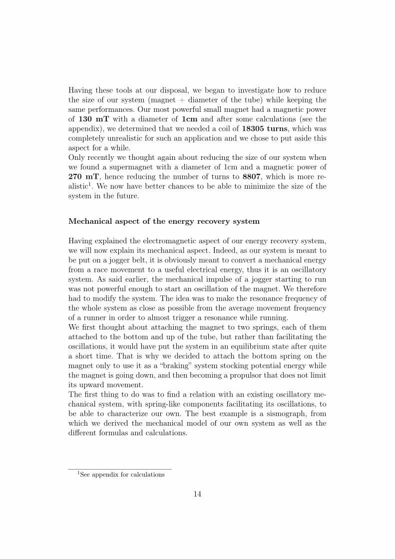
Input is a sinusoïde of amplitude 6.6Vmax and frequency 10 Hz. And we alsotested this circuit to obtain this graphic:
Figure 3.12: Test of the second rectifier (blue : Ve and clear blue : Vs)
As we can see, the input has been rectified without any voltage drop. Still,we have a big problem with this circuit even if it works perfectly. Indeed, itneeds a continuous source of tension to feed the operational amplifiers, whichwe do not have. . .
21

Switching system
We spent a lot of time researching a solution for an automatic switching fromone power supply to another when the runner stops.The idea was to use the electromagnetic generator to command the switch-ing circuit. Indeed, it provides a voltage during the race but not when it isstopped. We tried for a long time to find a solution based on active com-ponents but without any success as we still had the problem of having nocontinuous source of power in the system. We finally came out with the fol-lowing solution. The current will be guided in the capacity through diodesduring charging and the flow will be redirected to the LEDs when the voltageinput is less than the voltage across the capacity. The circuit is as follows:
Figure 3.13: Switch circuit
22

The problem is that this circuit imposes an input voltage important enoughto supply the capacity despite the diodes voltage drop. You will discover inthe next page the final circuit:
Figure 3.14: Final circuit
It is obvious that the power supply prototype we built is not efficient enoughto provide an appropriate voltage at the input of the storage system. Ournext prototype must be more efficient, hence optimized in different aspects,if we want to solve the energy storage problem.
23
3.1.3 Lightning system
The main advantage of LEDs is their efficiency in converting electrical powerinto optical power.
Design
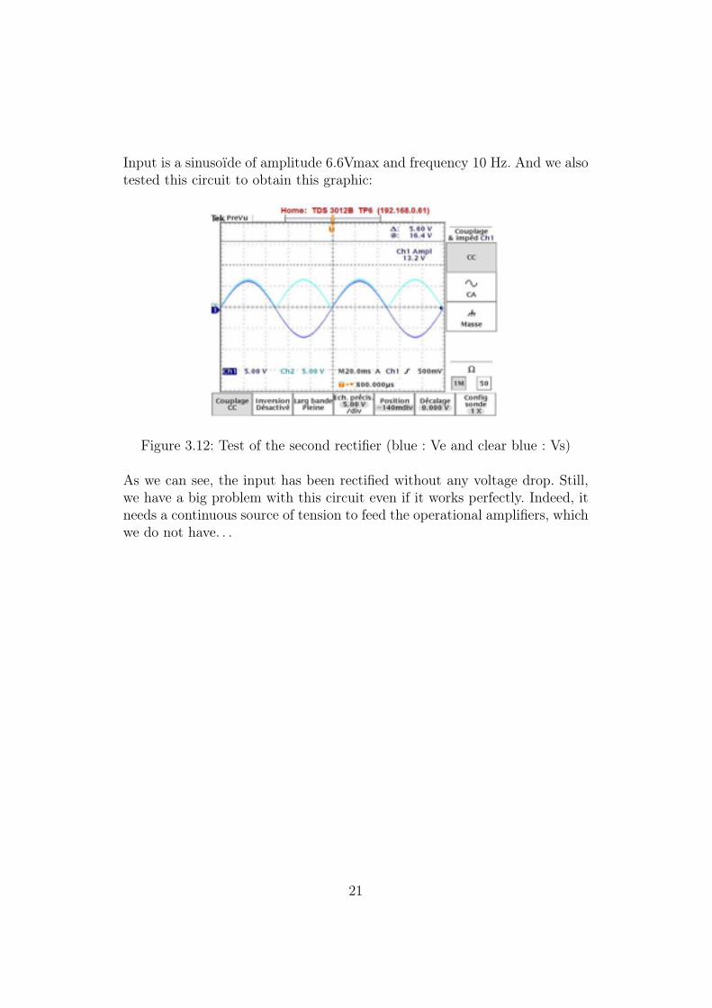
When a current is applied across the depletion region in forward bias (thenegative terminal of the supply is connected to the N-type material and thepositive to the p-type material), free electrons moving across a diode canfall into empty holes from the P-type layer . This involves a drop from theconduction band (free electrons) to a valance band (bound electrons). Whenthe electrons fall they release energy in the form of photons. The size of the
Figure 3.15: Amount of Energy released when an electron drops to valenceband and recombination occurs
gap determines the wavelength of the photon and thus, determines the colorof the light. Wavelength λ = hc/Eg thus the bigger is λ, the smaller Eg isand so, power supply voltage will be small.
Thus we are going to use red LEDs as they have the biggest wavelength.
The measuring units of light
These units are Candela, Watts,Lumens. Then, what are the correspondencesbetween them?
24

The sources emitting light are primary sources. For instance, the sun, theflame of a candle or a light bulb are primary sources. They emit light in alldirections and their intensity is measured in candelas (cd). Secondary sourcesare sources of lights that reflect the light. This luminous flux called luminanceis expressed in candelas per square meter (cd/m2). The source intensity (incandela) is height measured in the immediate vicinity of the light source.It is expressed in Candela (candela = lumen / steradian ) Luminous flux
Figure 3.16: Luminous flux
(in lumen) is the energy of a light emitted in a given direction. This flow isequal to 1 lumen if the source present at the base of the cone is 1 candela.Illumination (in lux) is the flow of light received. A surface receives one lux ifits surface is 1m 2 and if it is located perpendicular from a 1m distant sourceemitting one candela (lux = lumen/m2).A LED is made from a source which broadcasts in all directions and a mirrorwhich directs the beam of light.
Figure 3.17: LED (the arrow is pointing the reflector)
25

To evaluate the source intensity that we need to make our jogger visible bysomeone standing at 70 m, we will have to recall some trigonometric concepts.If we consider that luminous flux does not decrease with distance (which isrealistic), the luminous intensity received at a certain point is equal to theintensity of the source divided by the surface of the luminous cone:2πr2(1-cos(φ/2)) 3 .For the jogger to be visible, perceived light must be higherthan the ambient luminosity.
Figure 3.18: Light angle of a LED
For exemple:
For us, the perceived light must be higher than 0,0001lux.
3“r” distance jogger-driver and “φ” viewing angle of a LED
26

Performance requirements
The aim of our device is to make the jogger visible soon enough to give adriver coming at 50km/h enough time to react. We decided that five secondsto be a satisfactory requirement considering that the average human reactiontime is five seconds.Thus, we could deduce the distance from which the jogger should be visible:1 hour → 50kmtime to react → distancedistance=time to react*50km/hdistance= 5*50/3600 = 69,4m With the formula established in Chapter -2-1-2, we can find LEDs characteristics requirements:
Perceived light= Source intensity/(2πr2(1-cos(φ/2)))
If the viewing angle of the LEDs is 15 degree, then necessary source lightingintensity will be:0,0001= Source intensity/(2π(69,4)2(1-cos(7,5)))Source intensity=0,0259 Candela To conclude, LEDs will be red with aviewing angle of 15 degree and the total of LEDs intensity must be 25,9mCd.
27

Chapter 4
Challenge Jeunes Pousses
4.1 Presentation
The CJP or “Challenge Jeunes Pousses” is a contest in which several teamswith their own company creation projects are put in competition with acommon goal: winning the assistance of the “Incubateur PACA”, a companywhich helps young candidates in creating their own company. This help takesthe form of financial means and professional contacts.Obviously, the first thing to do to enter the CJP contest is to have a goodproject idea that can be used to create a company. As our project startedfrom a very promising idea, both commercially and technically speaking, wedecided to enter the challenge. The exact role of the CJP is to prepare thecandidates to participate to the semifinal and final with the true board ofexaminers from the sponsoring companies by giving us the means and expe-rience necessary to present a decent company creation package. We thereforehad several training meetings which subjects will be given later.The CJP team is organized as a team of people with different professionalspecializations that will give us their impressions on each team progress be-tween two meetings, and help us improve step by step until the semifinal andfinal. The examiners were mainly commercials, technicians and jurists.
28

Figure 4.1: The VisionergyTM Team (from left to right: JG MOUTON, C.BRESIN, A. DELANOE, S. ZANZOURI)
4.2 Professional experience
An important thing about the CJP is that it gives all the candidates a goodgeneral survey of a lot of aspects of the professional life. Indeed, each meetingconsisted in the presentations of each team progress (with a given theme towork on from one meeting to another), but also in presentations from variousexterior people about different professional aspects such as juridic, commer-cial, communication and management aspects. During the CJP adventure sofar, the given formation in all these domains helped us a lot in passing thesemifinal.Indeed, we had to think about protecting our project and thanks to the CJP,we learnt a lot of things about juridic aspects, like patents for example. Wegave a Soleau letter to the INPI and even the name VisionergyTM and thelogo are now protected.Moreover, we realized that communicate around our product was one of thebest means to obtain any possible help and to launch it on the market. Thatis why we made an advertisment flyer (see appendix) and a press commu-niqué that has been publicated in the local press. Convincing the examinerswas also a very good communication exercize and we will have to show ournew communication skills when requiring the help of people from variousprofessional domains in a near future.Being in a CJP team also requires the technical aspect of a project, that weare used to, to be closely related to the commercial aspect as it would be the
29

case for any project in a real company. Indeed, from its birth to its comple-tion, a project is primarily thought to be commercialized and we, technicians,often forget this aspect in our design process. We therefore had to learn tomake compromises and deal with the completely different way of thinking ofour commercial member to finally end up with the best possible project pack-age. Finally, we come to what we have learnt about project management. Wereceived a formation on how to organize and manage a work group and es-pecially any problem between members, as well as how to conduct a meetingand take the best from the cooperation of two different worlds: commercialand technical. It was not easy as we often faced a lot of disagreements on alot of subjects but always came to a compromise.As a result of this cooperation, we made a survey to decide about somethings such as the price for the final product or the main features we had toinclude in the design, as well as a business plan and a market study. Onlywith this kind of work were we able to convince the semifinal examiners thatour project was worth their interest. You can see below our two buisinessesprevisional plannings:
Figure 4.2: First previsional planning
As you can see we have two differents strategy for the development of theVisionergyTM Compagny.
30

Figure 4.3: Second previsional planning
4.3 Future of VisionergyTM
Now that we have passed the semifinal, the CJP has given us a chance ofimproving our project by supplying us with money and various contacts in theprofessional world. We have thus defined our objectives for the near future.First of all, we will have to solve our recurrent problem concerning the powerstorage system. The solution we came to seems viable but we have to improvethe voltage output of the linear dynamo. For that, we will need the help ofmechanical specialists, such as mechanics student in Polytech’Lille. Moreover,it is obvious that this system can be used for many more applications withthe appropriate design modifications. One of our future task will be to tryto transform the generator so that it can for example supply a mobile phoneor any small portable device with energy, thus charging the battery just bywalking.Then, we will have to look for new technologies like for example the upcomingOLEDs which electrical consumption is really small or the new “breathing”cloth which will greatly improve the comfort of the belt. After that, let’stalk about the future commercial aspects. While thinking about technicalimprovements, we will have to not neglect the commercial part of the project.We will need a a professional market study as well as a business plan reflectingthe reality of the market we want to penetrate to be able to end up with aviable company creation project. This as well requires a study of the futuredistribution channel and production chain (independent, Decathlon-type,...).It will also be necessary to think about our future advertisement and contact
31

the right people to enter the market as well as possible in order to possibly berepresented in advertisment supports displayed during big sportive events.Finally, we will also have to perform various related tasks such as registeringa patent, think about enlarging our team with capable people we are missingin some domains, and ensure the reliability and quality of our product in along term. Therefore, we will have to inform us about all the standards rulesand make the appropriate modifications and tests, such as EMC tests forexample.
32

Conclusion
Finally, we can conclude that this project was a very enriching experiencein that we had to deal with a lot of different disciplines such as photometry,quantum mechanics, mechanics, electromagnetism and electronics. The de-sign of a mechanically and electromagnetically optimized power generationsystem was therefore a demanding and interesting task with a lot of chal-lenges to overcome.Moreover, we also learnt a lot of useful things for our future professional lifeduring the CJP contest. Indeed, we had to deal with juridic aspects for theprotection of our product, with communication and management aspects aswell, and mainly to cooperate with a commercial team by making compro-mises between commercial and technical aspects.Overall, we also understood that the developpement of any new “clean” tech-nology was not an easy task. In our case, the fact that we did not have anybattery available obliged us to think a lot differently from what we were usedto in order to design our electronics. Therefore, it is a very creative task andone often has to change his way of thinking to design “clean” technologicalsystems.
33

Appendix A
Previsionnal Planning
34

Appendix B
Flyer
35

Appendix C
Electromagnetic calculations
Magnetic flux: (mettre la formule phi = B*S)φu: magnetic flux of a single coil turnn: number of coil turnsδt=31,25 ms half a semi-period of the magnet oscillation, corresponding fora cycle φ=0 to φ=max
1. 500 mT magnet: φu1 = 0,5*π?(1,75/2)2 = 1,2 T.cm2 = 0,00012 T.m2
2. 130 mT magnet: φu2 = 0,13*π?(1/2)2 = 0,102 T.cm2 = 0,0000102 T.m2
3. 270 mT magnet: φu3 = 0,27*π?(1/2)2 = 0,212 T.cm2 = 0,0000212 T.m2
We expressed φu in T.m2 to respect the S.I units for further calculations.Faraday law: (ici e= dφu/dt)We only take into account φu=0 and φu=max as the max peak voltage willdepend on this difference δφu.
1. 500 mT magnet: e1 = n1*(δφu1/δt) = 6V with n1=1556 turns. If wewant the same performances with the other weaker magnets, we needto keep e=6V and increase n.
2. 130 mT magnet: e2 = e1 = n1*(δφu1/δt) = n2*(δφu2/δt) = 6V andtherefore: n2 = n1*( δφu1/ δφu2) = 18305 turns
3. 270 mT magnet: n3 = n2*(δφu2/ δφu3) = 8807 turns
36

Appendix D
Mechanical model calculations
State 1: Mg=k1*x2 therefore: k1= Mg/x2 = 9 N.M
State 2: m(x”+y”)=k1-Cx’↔ y”= -x”-C/m*x’- ((k1+k2)/m)* x↔ (ω1)2*ym*exp(jω1t)= -(ω1)2*xm*exp(j( ω1t+φ)) – c/m*jω1*exp(j(ω1t+φ))- k1/m*xm* exp(j(ω1*t+φ) t=0: exp(jωt)=1:↔ (ω1)2 * ym= -(ω1)2*xm*exp(j*φ)- c/m*j ω1*exp(j*φ) - k1/m*xm*exp(j*φ)↔(ω1)2*(ym/xm)=exp(j*φ)*(-(ω1)2 - (c/m)*j ω1 - k1/m)↔exp(j*phi)=ym/xm*(-1 + j*m/C*ω1 - ω12/ω02)
↔ tan (φ)=((-C/m)*ω1)/((-ω12/ω02)-1) = (C/m)*ω1 / (ω12/ω02-1)
State 3: (x”+y”) = - (k1+k2)/M↔ y” = -x” - (k1+k2)/M↔ω12*ym*exp(-jω1t) = -ω12*xm*exp(-jω1t+φ) – ((k1+k2)/M)*xm*exp(-
jω1t+φ)↔(k2/M)*xm*exp(-jω1t+φ) = -ω12*xm*exp(-jω1t+φ) – (k1/M)*xm*exp(-
jω1t+φ) – w12*ym*exp(-jω1t)↔ k2/M = -ω12 – k1/M – (ym/xm)*(1/exp(jφ))↔ k2 = -Mω12 – k1 - M*(ym/xm)*(1/exp(jφ))
37