delaware department of transportation south …gssdocs.deldot.delaware.gov/bids/appendix a -...
TRANSCRIPT

Whitney, Bailey, Cox & Magnani, LLC Architects 1501 South Clinton Street, Suite 500 Baltimore, MD 21224
Whitney, Bailey, Cox & Magnani, LLC Consulting Engineers 849 Fairmount Avenue, Suite 100 Baltimore, MD 21286
Gipe Associates, Inc. Mechanical/Electrical Engineers 849 Fairmount Avenue, Suite 102 Baltimore, MD 21286
DELAWARE DEPARTMENT OF TRANSPORTATION SOUTH DISTRICT ADMINISTRATION BUILDING
ROOF & BOILER IMPROVEMENTS
STATE OF DELAWARE DEPARTMENT OF TRANSPORTATION
23697 SOUTH DUPONT BLVD. GEORGETOWN, DE 19947
CONTRACT NO. T201080107 WBCM Project No: 2008.0121.09
UNOFFICIAL WEBSITE COPY
DELAWARE DEPARTMENT OF TRANSPORTATION SOUTH DISTRICT ADMINISTRATION BUILDING ROOF & BOILER IMPROVEMENTS CONTRACT NO.: T201080107
Page 1
Division Section Title
DIVISION 01 - GENERAL REQUIREMENTS 011000 SUMMARY 014200 REFERENCES 017300 EXECUTION 017320 SELECTIVE DEMOLITION 017329 CUTTING AND PATCHING
DIVISION 05 - METALS 051200 STRUCTURAL STEEL FRAMING 053100 STEEL DECKING 055000 METAL FABRICATIONS
DIVISION 06 - WOOD, PLASTICS, AND COMPOSITES 061000 ROUGH CARPENTRY
DIVISION 07 - THERMAL AND MOISTURE PROTECTION 075423 THERMOPLASTIC POLYOLEFIN (TPO) ROOFING 077100 ROOF SPECIALTIES 079200 JOINT SEALANTS
DIVISION 09 - FINISHES 099123 INTERIOR PAINTING
DIVISION 15 - MECHANICAL 15100 GENERAL MECHANICAL REQUIREMENTS 15150 MECHANICAL FIRESTOPPING 15200 PIPING, FITTINGS, VALVES, ETC. 15300 MECHANICAL INSULATION 15400 PLUMBING 15500 PERFORMANCE TESTING AND BALANCING 15600 HEATING, VENTILATING AND AIR CONDITIONING 15700 AIR DISTRIBUTION 15975 VIBRATION CONTROL
DIVISION 16 - ELECTRICAL 16010 GENERAL ELECTRICAL REQUIREMENTS 16040 ELECTRICAL DEMOLITION 16050 BASIC ELECTRICAL MATERIALS AND METHODS 16071 ELECTRICAL SUPPORTING DEVICES 16075 ELECTRICAL IDENTIFICATION 16090 ELECTRICAL FIRESTOPPING 16120 CONDUCTORS AND CABLES 16130 RACEWAYS AND BOXES 16140 WIRING DEVICES 16452 GROUNDING
UNOFFICIAL WEBSITE COPY

DELAWARE DEPARTMENT OF TRANSPORTATION SOUTH DISTRICT ADMINISTRATION BUILDING ROOF & BOILER IMPROVEMENTS CONTRACT NO.: T201080107
Page 2
16470 PANELBOARDS 16475 FUSES 16476 DISCONNECT SWITCHES AND CIRCUIT BREAKERS 16481 ENCLOSED CONTROLLERS
END OF TABLE OF CONTENTS
UNOFFICIAL WEBSITE COPY
DELAWARE DEPARTMENT OF TRANSPORTATION SOUTH DISTRICT ADMINISTRATION BUILDING ROOF & BOILER IMPROVEMENTS CONTRACT NO.: T201080107
SUMMARY 011000 - 1
SECTION 011000 - SUMMARY
PART 1 - GENERAL
1.1 RELATED DOCUMENTS
A. Drawings, General and Supplementary Provisions of the contract, including but not limited to Section 100 of the DelDOT Standard Specifications for Road and Bridge Construction apply to this section.
1.2 SUMMARY
A. This Section includes the following:
1. Work covered by the Contract Documents. 2. Type of the Contract. 3. Use of premises. 4. Owner's occupancy requirements. 5. Work restrictions.
1.3 WORK COVERED BY CONTRACT DOCUMENTS
A. The Work consists of the following parts. All parts shall be phased and coordinated together.
1. Part I: Roof:
a. The project consists of the removal of existing roofing system down to existing metal deck and a new roofing system over existing low sloped metal deck.
b. The work also includes demolition of existing flashings, expansion joints, roof drains, roof curbs, roof blocking, roof access ladders, fascia flashings, counter flashing, copings, etc. and providing new of the aforementioned as well as splash blocks, downspouts, scuppers, and leader heads, etc.
2. Part II: Boiler Room:
a. The project consists of the removal of existing boiler room equipment (mechanical, electrical, piping and ductwork), brick chimney above the roof deck, concrete equipment pads and roofing above the boiler room.
b. The work also includes the installation of new boiler room equipment (mechanical, electrical, piping and ductwork), concrete equipment pads, and new structural steel to support two new stacks.
c. Interior finishes and painting are covered under this contract.
3. Part III: Centrifugal Exhaust Fans:
a. Install eleven (11) roof top, belt driven up blast centrifugal fans.
UNOFFICIAL WEBSITE COPY
DELAWARE DEPARTMENT OF TRANSPORTATION SOUTH DISTRICT ADMINISTRATION BUILDING ROOF & BOILER IMPROVEMENTS CONTRACT NO.: T201080107
SUMMARY 011000 - 2
b. The work also includes cutting openings in the existing roof deck, installation of new structural steel to support roof curbs and fans and providing the associated electrical wiring.
B. The work shall be done as shown on the Drawings and be completed in every respect and in conformance with all applicable requirements of the governing laws and codes.
C. The Contractor shall be responsible for the procurement and payment of all building permits, inspections, inspections by independent testing agencies, and coordination of all utility hookups/connections with appropriate suppliers/contractors. Other fees not mentioned herein directly related to the work, to satisfy the requirements of the contract documents are also the Contractors responsibility.
1.4 TYPE OF CONTRACT
A. Project will be constructed under a single prime contract.
1.5 USE OF PREMISES
A. General: Contractor shall have limited use of premises for construction operations as indicated on Drawings by the Contract limits.
B. Use of Site: Limit use of premises to work in areas indicated. Do not disturb portions of Project site beyond areas in which the Work is indicated.
1. Owner Occupancy: Allow for Owner occupancy of building. 2. Driveways and Entrances: Keep driveways and entrances serving premises clear and
available to Owner, Owner's employees, and emergency vehicles at all times. Do not use these areas for parking or storage of materials.
a. Schedule deliveries to minimize use of driveways and entrances. b. Schedule deliveries to minimize space and time requirements for storage of
materials and equipment on-site.
C. Use of Existing Building: Maintain existing building in a weathertight condition throughout construction period. Repair damage caused by construction operations. Protect building and its occupants during construction period.
1.6 OWNER'S OCCUPANCY REQUIREMENTS
A. Owner Occupancy: Owner will occupy the premises during entire construction period, with the exception of areas under construction. Cooperate with Owner during construction operations to minimize conflicts and facilitate Owner usage. Perform the Work so as not to interfere with Owner's operations. Maintain existing exits, unless otherwise indicated.
1. Maintain access to existing walkways, corridors, and other adjacent occupied or used facilities. Do not close or obstruct walkways, corridors, or other occupied or used facilities without written permission from Owner and authorities having jurisdiction.
2. Provide not less than 72 hours' notice to Owner of activities that will affect Owner's operations.
UNOFFICIAL WEBSITE COPY

DELAWARE DEPARTMENT OF TRANSPORTATION SOUTH DISTRICT ADMINISTRATION BUILDING ROOF & BOILER IMPROVEMENTS CONTRACT NO.: T201080107
SUMMARY 011000 - 3
1.7 WORK RESTRICTIONS
A. On-Site Work Hours: Work shall be generally performed inside the existing building during normal business working hours of 7:00 a.m. to 5:00 p.m., Monday through Friday, except otherwise indicated.
1. Weekend Hours: Saturday 7:00 a.m. to 5:00 p.m.
B. Existing Utility Interruptions: Do not interrupt utilities serving the facility occupied by Owner or others unless permitted under the following conditions and then only after arranging to provide temporary utility services according to requirements indicated:
1. Notify Owner in writing not less than 72 hours in advance of proposed utility interruptions. 2. Do not proceed with utility interruptions without Owner's written permission.
C. Nonsmoking Building: Smoking is not permitted within the building or within 25 feet of entrances, operable windows, or outdoor air intakes.
END OF SECTION 011000 UNOFFICIAL WEBSITE COPY

DELAWARE DEPARTMENT OF TRANSPORTATION SOUTH DISTRICT ADMINISTRATION BUILDING
ROOF & BOILER IMPROVEMENTS CONTRACT NO.: T201080107
REFERENCES 014200 - 1
SECTION 014200 - REFERENCES
PART 1 - GENERAL
1.1 RELATED DOCUMENTS
A. Drawings, General and Supplementary Provisions of the contract, including but not limited to Section 100 of the DelDOT Standard Specifications for Road and Bridge Construction apply to this section.
1.2 DEFINITIONS
A. General: Basic Contract definitions are included in the Conditions of the Contract.
B. "Approved": When used to convey the Engineer’s action on Contractor's submittals, applications, and requests, "approved" is limited to the Engineer’s duties and responsibilities as stated in the Conditions of the Contract.
C. "Directed": A command or instruction by the Engineer. Other terms including "requested," "authorized," "selected," "approved," "required," and "permitted" have the same meaning as "directed."
D. "Indicated": Requirements expressed by graphic representations or in written form on Drawings, in Specifications, and in other Contract Documents. Other terms including "shown," "noted," "scheduled," and "specified" have the same meaning as "indicated."
E. "Regulations": Laws, ordinances, statutes, and lawful orders issued by authorities having jurisdiction, and rules, conventions, and agreements within the construction industry that control performance of the Work.
F. "Furnish": Supply and deliver to Project site, ready for unloading, unpacking, assembly, installation, and similar operations.
G. "Install": Operations at Project site including unloading, temporarily storing, unpacking, assembling, erecting, placing, anchoring, applying, working to dimension, finishing, curing, protecting, cleaning, and similar operations.
H. "Provide": Furnish and install, complete and ready for the intended use.
I. "Installer": Contractor or another entity engaged by Contractor as an employee, Subcontractor, or Sub-subcontractor, to perform a particular construction operation, including installation, erection, application, and similar operations.
J. "Experienced": When used with an entity, "experienced" means having successfully completed a minimum of five previous projects similar in size and scope to this Project; being familiar with special requirements indicated; and having complied with requirements of authorities having jurisdiction.
UNOFFICIAL WEBSITE COPY

DELAWARE DEPARTMENT OF TRANSPORTATION SOUTH DISTRICT ADMINISTRATION BUILDING
ROOF & BOILER IMPROVEMENTS CONTRACT NO.: T201080107
REFERENCES 014200 - 2
K. "Project Site": Space available for performing construction activities. The extent of Project site is shown on Drawings and may or may not be identical with the description of the land on which Project is to be built.
1.3 INDUSTRY STANDARDS
A. Applicability of Standards: Unless the Contract Documents include more stringent requirements, applicable construction industry standards have the same force and effect as if bound or copied directly into the Contract Documents to the extent referenced. Such standards are made a part of the Contract Documents by reference.
B. Publication Dates: Comply with standards in effect as of date of the Contract Documents, unless otherwise indicated.
C. Conflicting Requirements: If compliance with two or more standards is specified and the standards establish different or conflicting requirements for minimum quantities or quality levels, comply with the most stringent requirement. Refer uncertainties and requirements that are different, but apparently equal, to the Engineer for a decision before proceeding.
1. Minimum Quantity or Quality Levels: The quantity or quality level shown or specified shall be the minimum provided or performed. The actual installation may comply exactly with the minimum quantity or quality specified, or it may exceed the minimum within reasonable limits. To comply with these requirements, indicated numeric values are minimum or maximum, as appropriate, for the context of requirements. Refer uncertainties to the Engineer for a decision before proceeding.
1.4 ABBREVIATIONS AND ACRONYMS
A. Industry Organizations: Where abbreviations and acronyms are used in Specifications or other Contract Documents, they shall mean the recognized name of the entities indicated in Gale Research's "Encyclopedia of Associations" or in Columbia Books' "National Trade & Professional Associations of the U.S."
AGC Associated General Contractors of America (The) (703) 548-3118 www.agc.org AI Asphalt Institute (859) 288-4960 www.asphaltinstitute.org AIA American Institute of Architects (The) (202) 626-7300 www.e-the architect.com ANSI American National Standards Institute (202) 293-8020 www.ansi.org CSI Construction Specifications Institute (The) (800) 689-2900 www.csinet.org (703) 684-0300 FM Factory Mutual System (See FMG)
UNOFFICIAL WEBSITE COPY

DELAWARE DEPARTMENT OF TRANSPORTATION SOUTH DISTRICT ADMINISTRATION BUILDING
ROOF & BOILER IMPROVEMENTS CONTRACT NO.: T201080107
REFERENCES 014200 - 3
FMG FM Global (401) 275-3000 (Formerly: FM - Factory Mutual System) www.fmglobal.com NAAMM National Association of The Engineerural Metal
Manufacturers (312) 332-0405
www.naamm.org NFPA National Fire Protection Association (800) 344-3555 www.nfpa.org (617) 770-3000 NRCA National Roofing Contractors Association (800) 323-9545 www.nrca.net (847) 299-9070 SDI Steel Deck Institute (847) 462-1930 www.sdi.org SPRI SPRI (781) 444-0242 (Single Ply Roofing Institute) www.spri.org UL Underwriters Laboratories Inc. (800) 704-4050 www.ul.com (847) 272-8800 WWPA Western Wood Products Association (503) 224-3930 www.wwpa.org
B. Code Agencies: Where abbreviations and acronyms are used in Specifications or other Contract Documents, they shall mean the recognized name of the entities in the following list. Names, telephone numbers, and Web site addresses are subject to change and are believed to be accurate and up-to-date as of the date of the Contract Documents.
BOCA BOCA International, Inc. (708) 799-2300 www.bocai.org
C. Federal Government Agencies: Where abbreviations and acronyms are used in Specifications or other Contract Documents, they shall mean the recognized name of the entities in the following list. Names, telephone numbers, and Web site addresses are subject to change and are believed to be accurate and up-to-date as of the date of the Contract Documents.
EPA Environmental Protection Agency (202) 260-2090 www.epa.gov NIST National Institute of Standards and Technology (301) 975-6478 www.nist.gov OSHA Occupational Safety & Health Administration (202) 693-1999
UNOFFICIAL WEBSITE COPY

DELAWARE DEPARTMENT OF TRANSPORTATION SOUTH DISTRICT ADMINISTRATION BUILDING
ROOF & BOILER IMPROVEMENTS CONTRACT NO.: T201080107
REFERENCES 014200 - 4
www.osha.gov
END OF SECTION 014200
UNOFFICIAL WEBSITE COPY

DELAWARE DEPARTMENT OF TRANSPORTATION SOUTH DISTRICT ADMINISTRATION BUILDING ROOF & BOILER IMPROVEMENTS CONTRACT NO.: T201080107
EXECUTION 017300 - 1
SECTION 017300 - EXECUTION
PART 1 - GENERAL
1.1 RELATED DOCUMENTS
A. Drawings, General and Supplementary Provisions of the contract, including but not limited to Section 100 of the DelDOT Standard Specifications for Road and Bridge Construction apply to this section.
1.2 SUMMARY
A. This Section includes general procedural requirements governing execution of the Work including, but not limited to, the following:
1. General installation of products. 2. Progress cleaning. 3. Starting and adjusting. 4. Protection of installed construction. 5. Correction of the Work.
PART 2 - EXECUTION
2.1 EXAMINATION
A. Existing Conditions: The existence and location of site improvements, utilities, and other construction indicated as existing are not guaranteed. Before beginning work, investigate and verify the existence and location of mechanical and electrical systems and other construction affecting the Work.
1. Before construction, verify the location and points of connection of utility services.
B. Existing Utilities: The existence and location of underground and other utilities and construction indicated as existing are not guaranteed. Before beginning sitework, investigate and verify the existence and location of underground utilities and other construction affecting the Work.
1. Before construction, verify the location and invert elevation at points of connection of sanitary sewer, storm sewer, and water-service piping; and underground electrical services.
2. Furnish location data for work related to Project that must be performed by public utilities serving Project site.
C. Acceptance of Conditions: Examine substrates, areas, and conditions, with Installer or Applicator present where indicated, for compliance with requirements for installation tolerances and other conditions affecting performance. Record observations.
UNOFFICIAL WEBSITE COPY
DELAWARE DEPARTMENT OF TRANSPORTATION SOUTH DISTRICT ADMINISTRATION BUILDING ROOF & BOILER IMPROVEMENTS CONTRACT NO.: T201080107
EXECUTION 017300 - 2
1. Verify compatibility with and suitability of substrates, including compatibility with existing finishes or primers.
2. Examine roughing-in for mechanical and electrical systems to verify actual locations of connections before equipment and fixture installation.
3. Examine walls, floors, and roofs for suitable conditions where products and systems are to be installed.
4. Proceed with installation only after unsatisfactory conditions have been corrected. Proceeding with the Work indicates acceptance of surfaces and conditions.
2.2 PREPARATION
A. Existing Utility Information: Furnish information to local utility that is necessary to adjust, move, or relocate existing utility structures, utility poles, lines, services, or other utility appurtenances located in or affected by construction. Coordinate with authorities having jurisdiction.
B. Field Measurements: Take field measurements as required to fit the Work properly. Recheck measurements before installing each product. Where portions of the Work are indicated to fit to other construction, verify dimensions of other construction by field measurements before fabrication. Coordinate fabrication schedule with construction progress to avoid delaying the Work.
C. Space Requirements: Verify space requirements and dimensions of items shown diagrammatically on Drawings.
D. Review of Contract Documents and Field Conditions: Immediately on discovery of the need for clarification of the Contract Documents, submit a request for information to the Engineer. Include a detailed description of problem encountered, together with recommendations for changing the Contract Documents.
2.3 INSTALLATION
A. General: Locate the Work and components of the Work accurately, in correct alignment and elevation, as indicated.
1. Make vertical work plumb and make horizontal work level. 2. Where space is limited, install components to maximize space available for maintenance
and ease of removal for replacement. 3. Conceal pipes, ducts, and wiring in finished areas, unless otherwise indicated.
B. Comply with manufacturer's written instructions and recommendations for installing products in applications indicated.
C. Install products at the time and under conditions that will ensure the best possible results. Maintain conditions required for product performance until Substantial Completion.
D. Conduct construction operations so no part of the Work is subjected to damaging operations or loading in excess of that expected during normal conditions of occupancy.
E. Tools and Equipment: Do not use tools or equipment that produce harmful noise levels.
UNOFFICIAL WEBSITE COPY

DELAWARE DEPARTMENT OF TRANSPORTATION SOUTH DISTRICT ADMINISTRATION BUILDING ROOF & BOILER IMPROVEMENTS CONTRACT NO.: T201080107
EXECUTION 017300 - 3
F. Templates: Obtain and distribute to the parties involved templates for work specified to be factory prepared and field installed. Check Shop Drawings of other work to confirm that adequate provisions are made for locating and installing products to comply with indicated requirements.
G. Anchors and Fasteners: Provide anchors and fasteners as required to anchor each component securely in place, accurately located and aligned with other portions of the Work.
1. Mounting Heights: Where mounting heights are not indicated, mount components at heights directed by the Engineer.
2. Allow for building movement, including thermal expansion and contraction. 3. Coordinate installation of anchorages. Furnish setting drawings, templates, and
directions for installing anchorages, including sleeves, concrete inserts, anchor bolts, and items with integral anchors, that are to be embedded in concrete or masonry. Deliver such items to Project site in time for installation.
H. Joints: Make joints of uniform width. Where joint locations in exposed work are not indicated, arrange joints for the best visual effect. Fit exposed connections together to form hairline joints.
I. Hazardous Materials: Use products, cleaners, and installation materials that are not considered hazardous.
2.4 PROGRESS CLEANING
A. General: Clean Project site and work areas daily, including common areas. Coordinate progress cleaning for joint-use areas where more than one installer has worked. Enforce requirements strictly. Dispose of materials lawfully.
1. Comply with requirements in NFPA 241 for removal of combustible waste materials and debris.
2. Do not hold materials more than 7 days during normal weather or 3 days if the temperature is expected to rise above 80 deg F.
3. Containerize hazardous and unsanitary waste materials separately from other waste. Mark containers appropriately and dispose of legally, according to regulations.
B. Site: Maintain Project site free of waste materials and debris.
C. Work Areas: Clean areas where work is in progress to the level of cleanliness necessary for proper execution of the Work.
1. Remove liquid spills promptly. 2. Where dust would impair proper execution of the Work, broom-clean or vacuum the
entire work area, as appropriate.
D. Installed Work: Keep installed work clean. Clean installed surfaces according to written instructions of manufacturer or fabricator of product installed, using only cleaning materials specifically recommended. If specified cleaning materials are not recommended, use cleaning materials that are not hazardous to health or property and that will not damage exposed surfaces.
E. Concealed Spaces: Remove debris from concealed spaces before enclosing the space.
UNOFFICIAL WEBSITE COPY
DELAWARE DEPARTMENT OF TRANSPORTATION SOUTH DISTRICT ADMINISTRATION BUILDING ROOF & BOILER IMPROVEMENTS CONTRACT NO.: T201080107
EXECUTION 017300 - 4
F. Exposed Surfaces in Finished Areas: Clean exposed surfaces and protect as necessary to ensure freedom from damage and deterioration at time of Substantial Completion.
G. Waste Disposal: Burying or burning waste materials on-site will not be permitted. Washing waste materials down sewers or into waterways will not be permitted.
H. During handling and installation, clean and protect construction in progress and adjoining materials already in place. Apply protective covering where required to ensure protection from damage or deterioration at Substantial Completion.
I. Clean and provide maintenance on completed construction as frequently as necessary through the remainder of the construction period. Adjust and lubricate operable components to ensure operability without damaging effects.
J. Limiting Exposures: Supervise construction operations to assure that no part of the construction, completed or in progress, is subject to harmful, dangerous, damaging, or otherwise deleterious exposure during the construction period.
2.5 RECYCLABLE MATERIALS
A. Architectural sheet metals, extruded metals, metal structural components shall be stored in separate containers and recycled.
B. If possible, removed roof aggregate shall be recycled.
C. Recyclable material shall be placed in separate containers from those containing demolition and construction waste and be disposed of in an appropriate facility.
2.6 STARTING AND ADJUSTING
A. Start equipment and operating components to confirm proper operation. Remove malfunctioning units, replace with new units, and retest.
B. Adjust operating components for proper operation without binding. Adjust equipment for proper operation.
C. Test each piece of equipment to verify proper operation. Test and adjust controls and safeties. Replace damaged and malfunctioning controls and equipment.
2.7 PROTECTION OF INSTALLED CONSTRUCTION
A. Provide final protection and maintain conditions that ensure installed Work is without damage or deterioration at time of Substantial Completion.
B. Comply with manufacturer's written instructions for temperature and relative humidity.
2.8 CORRECTION OF THE WORK
UNOFFICIAL WEBSITE COPY

DELAWARE DEPARTMENT OF TRANSPORTATION SOUTH DISTRICT ADMINISTRATION BUILDING ROOF & BOILER IMPROVEMENTS CONTRACT NO.: T201080107
EXECUTION 017300 - 5
A. Repair or remove and replace defective construction. Restore damaged substrates and finishes.
1. Repairing includes replacing defective parts, refinishing damaged surfaces, touching up with matching materials, and properly adjusting operating equipment.
B. Restore permanent facilities used during construction to their specified condition.
C. Remove and replace damaged surfaces that are exposed to view if surfaces cannot be repaired without visible evidence of repair.
D. Repair components that do not operate properly. Remove and replace operating components that cannot be repaired.
E. Remove and replace chipped, scratched, and broken glass or reflective surfaces.
END OF SECTION 017300 UNOFFICIAL WEBSITE COPY

DELAWARE DEPARTMENT OF TRANSPORTATION SOUTH DISTRICT ADMINISTRATION BUILDING ROOF & BOILER IMPROVEMENTS CONTRACT NO.: T201080107
SELECTIVE DEMOLITION 017320 - 1
SECTION 017320 - SELECTIVE DEMOLITION
PART 1 - GENERAL
1.1 RELATED DOCUMENTS
A. Drawings, General and Supplementary Provisions of the contract, including but not limited to Section 100 of the DelDOT Standard Specifications for Road and Bridge Construction apply to this section.
1.2 SUMMARY
A. This Section includes the following:
1. Demolition and removal of selected portions of a building or structure. 2. Repair procedures for selective demolition operations.
1.3 DEFINITIONS
A. Remove: Detach items from existing construction and legally dispose of them off-site, unless indicated to be removed and salvaged or removed and reinstalled.
B. Remove and Salvage: Detach items from existing construction and deliver them to Owner.
C. Remove and Reinstall: Detach items from existing construction, prepare them for reuse, and reinstall them where indicated.
D. Existing to Remain: Existing items of construction that are not to be removed and that are not otherwise indicated to be removed, removed and salvaged, or removed and reinstalled.
1.4 MATERIALS OWNERSHIP
A. Except for items or materials indicated to be reused, salvaged, reinstalled, or otherwise indicated to remain Owner's property, demolished materials shall become Contractor's property and shall be removed from Project site.
1.5 SUBMITTALS
A. Qualification Data: For firms and persons specified in "Quality Assurance" Article to demonstrate their capabilities and experience. Include lists of completed projects with project names and addresses, names and addresses of architects and owners, and other information specified.
UNOFFICIAL WEBSITE COPY

DELAWARE DEPARTMENT OF TRANSPORTATION SOUTH DISTRICT ADMINISTRATION BUILDING ROOF & BOILER IMPROVEMENTS CONTRACT NO.: T201080107
SELECTIVE DEMOLITION 017320 - 2
B. Proposed Dust-Control and Noise-Control Measures: Submit statement or drawing that indicates the measures proposed for use, proposed locations, and proposed time frame for their operation. Identify options if proposed measures are later determined to be inadequate.
C. Schedule of Selective Demolition Activities: Indicate the following:
1. Detailed sequence of selective demolition and removal work, with starting and ending dates for each activity. Ensure Owner's on-site operations are uninterrupted.
2. Coordination for shutoff and continuation of utility services. 3. Coordination of Owner's continuing occupancy of portions of existing building.
D. Predemolition Photographs: Show existing conditions of adjoining construction and site improvements, including finish surfaces, that might be misconstrued as damage caused by selective demolition operations. Submit before Work begins.
E. Landfill Records: Indicate receipt and acceptance of hazardous wastes by a landfill facility licensed to accept hazardous wastes.
F. Recyclable Materials: Indicate receipt and acceptance of recyclable wastes by associated recycling facility licensed to accept recyclable materials.
1.6 QUALITY ASSURANCE
A. Demolition Firm Qualifications: An experienced firm that has specialized in demolition work similar in material and extent to that indicated for this Project.
B. Professional Engineer Qualifications: Registered Professional Engineer in the State of Delaware.
C. Regulatory Requirements: Comply with governing EPA notification regulations before beginning selective demolition. Comply with hauling and disposal regulations of authorities having jurisdiction.
D. Standards: Comply with ANSI A10.6 and NFPA 241.
1.7 PROJECT CONDITIONS
A. Owner will occupy building during selective demolition. Conduct selective demolition so Owner's operations will not be disrupted. Provide not less than 72 hours' written notice to Owner of activities that will affect Owner's operations.
B. Maintain access to existing walkways, corridors, and other adjacent occupied or used facilities.
1. Do not close or obstruct walkways, corridors, or other occupied or used facilities without written permission from authorities having jurisdiction.
C. Owner assumes no responsibility for condition of areas to be selectively demolished.
1. Conditions existing at time of inspection for bidding purpose will be maintained by Owner as far as practical.
2. Before selective demolition, Owner will remove the following items:
UNOFFICIAL WEBSITE COPY

DELAWARE DEPARTMENT OF TRANSPORTATION SOUTH DISTRICT ADMINISTRATION BUILDING ROOF & BOILER IMPROVEMENTS CONTRACT NO.: T201080107
SELECTIVE DEMOLITION 017320 - 3
a. Security cameras.
D. Hazardous Materials: It is not expected that hazardous materials will be encountered in the Work.
1. If materials suspected of containing hazardous materials are encountered, do not disturb; immediately notify Owner. Hazardous materials will be removed by Owner under a separate contract.
E. Storage or sale of removed items or materials on-site will not be permitted.
F. Utility Service: Maintain existing utilities in service and protect them against damage during selective demolition operations.
1. Maintain fire-protection facilities in service during selective demolition operations.
1.8 WARRANTY
A. Existing Warranties: Remove, replace, patch, and repair materials and surfaces cut or damaged during selective demolition, by methods and with materials so as not to void existing warranties.
PART 2 - PRODUCTS
2.1 REPAIR MATERIALS
A. Use repair materials identical to existing materials.
1. If identical materials are unavailable or cannot be used for exposed surfaces, use materials that visually match existing adjacent surfaces to the fullest extent possible.
2. Use materials whose installed performance equals or surpasses that of existing materials.
B. Comply with material and installation requirements specified in individual Specification Sections.
PART 3 - EXECUTION
3.1 EXAMINATION
A. Verify that utilities have been disconnected and capped.
B. Survey existing conditions and correlate with requirements indicated to determine extent of selective demolition required.
C. Inventory and record the condition of items to be removed and reinstalled and items to be removed and salvaged.
UNOFFICIAL WEBSITE COPY
DELAWARE DEPARTMENT OF TRANSPORTATION SOUTH DISTRICT ADMINISTRATION BUILDING ROOF & BOILER IMPROVEMENTS CONTRACT NO.: T201080107
SELECTIVE DEMOLITION 017320 - 4
D. When unanticipated mechanical, electrical, or structural elements that conflict with intended function or design are encountered, investigate and measure the nature and extent of conflict. Promptly submit a written report to the Engineer.
E. Perform surveys as the Work progresses to detect hazards resulting from selective demolition activities.
F. Maintain existing building in a weathertight condition throughout construction period. Repair damage caused by construction operations. Protect building, its contents and its occupants during construction period. The contractor shall be responsible for all real and verifiable damages, including costs for loss of work by the Owner’s employees, resulting from the contractor’s inability to provide a weathertight and safe working environment in the Owner’s buildings. All temporary conditions required to meet the conditions above shall be the sole responsibility of the Contractor to design, maintain and enforce with their forces and those of their subcontractors. All temporary facilities shall be maintained during off-work hours in a safe and secured condition.
3.2 UTILITY SERVICES
A. Existing Utilities: Maintain services and protect them against damage during selective demolition operations.
B. Do not interrupt existing utilities serving occupied or operating facilities unless authorized in writing by Owner and authorities having jurisdiction. Provide temporary services during interruptions to existing utilities, as acceptable to Owner and to authorities having jurisdiction.
1. Provide at least 72 hours' written notice to Owner if shutdown of service is required during changeover.
C. Temporary Enclosures: Provide temporary enclosures for protection of existing building and construction, in progress and completed, from exposure, foul weather, other construction operations, and similar activities.
3.3 POLLUTION CONTROLS
A. Dust Control: Use water mist, temporary enclosures, and other suitable methods to limit spread of dust and dirt. Comply with governing environmental-protection regulations.
1. Do not use water when it may damage existing construction or create hazardous or objectionable conditions, such as ice, flooding, and pollution.
B. Disposal: Remove and transport debris in a manner that will prevent spillage on adjacent surfaces and areas.
1. Remove debris from elevated portions of building by chute, hoist, or other device that will convey debris to grade level in a controlled descent.
C. Cleaning: Clean adjacent structures and improvements of dust, dirt, and debris caused by selective demolition operations. Return adjacent areas to condition existing before selective demolition operations began.
UNOFFICIAL WEBSITE COPY

DELAWARE DEPARTMENT OF TRANSPORTATION SOUTH DISTRICT ADMINISTRATION BUILDING ROOF & BOILER IMPROVEMENTS CONTRACT NO.: T201080107
SELECTIVE DEMOLITION 017320 - 5
3.4 SELECTIVE DEMOLITION
A. General: Demolish and remove existing construction only to the extent required by new construction and as indicated. Use methods required to complete the Work within limitations of governing regulations and as follows:
1. Neatly cut openings and holes plumb, square, and true to dimensions required. Use cutting methods least likely to damage construction to remain or adjoining construction. Use hand tools or small power tools designed for sawing or grinding, not hammering and chopping, to minimize disturbance of adjacent surfaces. Temporarily cover openings to remain.
2. Cut or drill from the exposed or finished side into concealed surfaces to avoid marring existing finished surfaces.
3. Do not use cutting torches until work area is cleared of flammable materials. At concealed spaces, such as duct and pipe interiors, verify condition and contents of hidden space before starting flame-cutting operations. Maintain fire watch and portable fire-suppression devices during flame-cutting operations.
4. Maintain adequate ventilation when using cutting torches. 5. Remove decayed, vermin-infested, or otherwise dangerous or unsuitable materials and
promptly dispose of off-site. 6. Remove structural framing members and lower to ground by method suitable to avoid
free fall and to prevent ground impact or dust generation. Remove items from the rooftop level and not through the building.
7. Locate selective demolition equipment and remove debris and materials so as not to impose excessive loads on supporting walls, floors, or framing.
8. Dispose of demolished items and materials promptly. 9. Return elements of construction and surfaces that are to remain to condition existing
before selective demolition operations began.
B. Removed and Reinstalled Items: Comply with the following:
1. Clean and repair items to functional condition adequate for intended reuse. Paint equipment to match new equipment.
2. Pack or crate items after cleaning and repairing. Identify contents of containers. 3. Protect items from damage during transport and storage. 4. Reinstall items in locations indicated. Comply with installation requirements for new
materials and equipment. Provide connections, supports, and miscellaneous materials necessary to make item functional for use indicated.
C. Existing Items to Remain: Protect construction indicated to remain against damage and soiling during selective demolition. When permitted by the Engineer, items may be removed to a suitable, protected storage location during selective demolition and cleaned and reinstalled in their original locations after selective demolition operations are complete.
D. Roofing: Remove no more existing roofing and flashing materials than can be covered in one day by new roofing or flashing.
3.5 PATCHING AND REPAIRS
A. General: Promptly repair damage to adjacent construction caused by selective demolition operations.
UNOFFICIAL WEBSITE COPY

DELAWARE DEPARTMENT OF TRANSPORTATION SOUTH DISTRICT ADMINISTRATION BUILDING ROOF & BOILER IMPROVEMENTS CONTRACT NO.: T201080107
SELECTIVE DEMOLITION 017320 - 6
B. Repairs: Where repairs to existing surfaces are required, patch to produce surfaces suitable for new materials.
C. Finishes: Restore exposed finishes of patched areas and extend restoration into adjoining construction in a manner that eliminates evidence of patching and refinishing.
3.6 DISPOSAL OF DEMOLISHED MATERIALS
A. General: Promptly dispose of demolished materials. Do not allow demolished materials to accumulate on-site.
B. Burning: Do not burn demolished materials.
C. Disposal: Transport demolished materials off Owner's property and legally dispose of them.
END OF SECTION 017320 UNOFFICIAL WEBSITE COPY

DELAWARE DEPARTMENT OF TRANSPORTATION SOUTH DISTRICT ADMINISTRATION BUILDING ROOF & BOILER IMPROVEMENTS CONTRACT NO.: T201080107
CUTTING AND PATCHING 017329 - 1
SECTION 017329 - CUTTING AND PATCHING
PART 1 - GENERAL
1.1 RELATED DOCUMENTS
A. Drawings, General and Supplementary Provisions of the contract, including but not limited to Section 100 of the DelDOT Standard Specifications for Road and Bridge Construction apply to this section.
1.2 SUMMARY
A. This Section includes procedural requirements for cutting and patching.
1.3 DEFNITIONS
A. Cutting: Removal of existing construction necessary to permit installation or performance of other Work.
B. Patching: Fitting and repair work required to restore surfaces to original conditions after installation of other Work.
1.4 SUBMITTALS
A. Cutting and Patching Proposal: Submit a proposal describing procedures at least 10 days before the time cutting and patching will be performed, requesting approval to proceed. Include the following information:
1. Extent: Describe cutting and patching, show how they will be performed. 2. Changes to Existing Construction: Describe anticipated results. Include changes to
structural elements as well as changes in building's appearance and other significant visual elements.
3. Products: List products to be used and firms or entities that will perform the Work. 4. Dates: Indicate when cutting and patching will be performed.
5. Utilities: List utilities that cutting and patching procedures will disturb or affect. List utilities that will be relocated and those that will be temporarily out of service. Indicate how long service will be disrupted.
6. Structural Elements: Where cutting and patching involve adding reinforcement to structural elements, submit details and engineering calculations showing integration of reinforcement with original structure.
UNOFFICIAL WEBSITE COPY

DELAWARE DEPARTMENT OF TRANSPORTATION SOUTH DISTRICT ADMINISTRATION BUILDING ROOF & BOILER IMPROVEMENTS CONTRACT NO.: T201080107
CUTTING AND PATCHING 017329 - 2
1.5 QUALITY ASSURANCE
A. Structural Elements: Do not cut and patch structural elements in a manner that could change their load-carrying capacity or load-deflection ratio.
1. This includes structural beams and metal decking at roof substrate.
B. Operational Elements: Do not cut and patch operating elements.
C. Miscellaneous Elements: Do not cut and patch the following elements or related components in a manner that could change their load-carrying capacity, that results in reducing their capacity to perform as intended, or that results in increased maintenance or decreased operational life or safety.
1. Membranes and flashings, except those indicated. 2. Equipment supports. 3. Piping, ductwork, vessels, and equipment. 4. Noise- and vibration-control elements and systems.
D. Visual Requirements: Do not cut and patch construction in a manner that results in visual evidence of cutting and patching. Do not cut and patch construction exposed on the exterior or in occupied spaces in a manner that would, in the Engineer's opinion, reduce the building's aesthetic qualities. Remove and replace construction that has been cut and patched in a visually unsatisfactory manner.
1. If possible, retain original Installer or fabricator to cut and patch exposed Work listed below. If it is impossible to engage original Installer or fabricator, engage another recognized, experienced, and specialized firm.
a. Preformed metal panels, copings and metal trim. b. Roofing and flashings.
E. Cutting and Patching Conference: Before proceeding, meet at Project site with parties involved in cutting and patching. Review areas of potential interference and conflict. Coordinate procedures and resolve potential conflicts before proceeding.
1.6 WARRANTY
A. Existing Warranties: Remove, replace, patch, and repair materials and surfaces cut or damaged during cutting and patching operations, by methods and with materials so as not to void existing warranties.
PART 2 - PRODUCTS
2.1 MATERIALS
A. General: Comply with requirements specified in other Sections of these Specifications.
UNOFFICIAL WEBSITE COPY
DELAWARE DEPARTMENT OF TRANSPORTATION SOUTH DISTRICT ADMINISTRATION BUILDING ROOF & BOILER IMPROVEMENTS CONTRACT NO.: T201080107
CUTTING AND PATCHING 017329 - 3
B. Existing Materials: Use materials identical to existing materials. For exposed surfaces, use materials that visually match existing adjacent surfaces to the fullest extent possible.
1. If identical materials are unavailable or cannot be used, use materials that, when installed, will match the visual and functional performance of existing materials.
PART 3 - EXECUTION
3.1 EXAMINATION
A. Examine surfaces to be cut and patched and conditions under which cutting and patching are to be performed.
1. Compatibility: Before patching, verify compatibility with and suitability of substrates, including compatibility with existing finishes or primers.
2. Proceed with installation only after unsafe or unsatisfactory conditions have been corrected.
3.2 PREPARATION
A. Temporary Support: Provide temporary support of Work to be cut.
B. Protection: Protect existing construction during cutting and patching to prevent damage. Provide protection from adverse weather conditions for portions of Project that might be exposed during cutting and patching operations.
C. Adjoining Areas: Avoid interference with use of adjoining areas or interruption of free passage to adjoining areas.
3.3 PERFORMANCE
A. General: Employ skilled workers to perform cutting and patching. Proceed with cutting and patching at the earliest feasible time, and complete without delay.
1. Cut existing construction to provide for installation of other components or performance of other construction, and subsequently patch as required to restore surfaces to their original condition.
B. Cutting: Cut existing construction by sawing, drilling, breaking, chipping, grinding, and similar operations, using methods least likely to damage elements retained or adjoining construction. If possible, review proposed procedures with original Installer; comply with original Installer's written recommendations.
1. In general, use hand or small power tools designed for sawing and grinding, not hammering and chopping. Cut holes and slots as small as possible, neatly to size required, and with minimum disturbance of adjacent surfaces. Temporarily cover openings when not in use.
2. Existing Finished Surfaces: Cut or drill from the exposed or finished side into concealed surfaces.
UNOFFICIAL WEBSITE COPY
DELAWARE DEPARTMENT OF TRANSPORTATION SOUTH DISTRICT ADMINISTRATION BUILDING ROOF & BOILER IMPROVEMENTS CONTRACT NO.: T201080107
CUTTING AND PATCHING 017329 - 4
3. Proceed with patching after construction operations requiring cutting are complete.
C. Patching: Patch construction by filling, repairing, refinishing, closing up, and similar operations following performance of other Work. Patch with durable seams that are as invisible as possible. Provide materials and comply with installation requirements specified in other Sections of these Specifications.
1. Inspection: Where feasible, test and inspect patched areas after completion to demonstrate integrity of installation.
2. Exposed Finishes: Restore exposed finishes of patched areas and extend finish restoration into retained adjoining construction in a manner that will eliminate evidence of patching and refinishing.
3. Exterior Building Enclosure: Patch components in a manner that restores enclosure to a weathertight condition.
END OF SECTION 017329 UNOFFICIAL WEBSITE COPY

DELAWARE DEPARTMENT OF TRANSPORTATION SOUTH DISTRICT ADMINISTRATION BUILDING
ROOF & BOILER IMPROVEMENTS CONTRACT NO.: T201080107
STRUCTURAL STEEL FRAMING 051200 – 1
SECTION 051200 - STRUCTURAL STEEL FRAMING
PART 1 - GENERAL
1.1 RELATED DOCUMENTS
A. Drawings, General and Supplementary Provisions of the contract, including but not limited to Section 100 of the DelDOT Standard Specifications for Road and Bridge Construction apply to this section.
1.2 SUMMARY
A. This Section includes the following:
1. Structural steel. 2. Architecturally exposed structural steel. 3. Prefabricated building columns. 4. Grout.
1.3 DEFINITIONS
A. Structural Steel: Elements of structural-steel frame, as classified by AISC’s “Code of Standard Practice for Steel Buildings and Bridges,” that support design loads.
B. Architecturally Exposed Structural Steel: Structural steel designated as architecturally exposed structural steel in the Contract Documents.
1.4 PERFORMANCE REQUIREMENTS
A. Connections: Provide details of simple shear connections required by the Contract Documents to be selected or completed by structural-steel fabricator to withstand Allowable Stress Design -service loads indicated and comply with other information and restrictions indicated. 1. Select and complete connections using schematic details indicated and AISC’s “Manual
of Steel Construction, Load and Resistance Factor Design,” Volume 2, Part 9, AISC’s “Manual of Steel Construction, Allowable Stress Design,” Part 4.
2. Engineering Responsibility: Fabricator’s responsibilities include using a registered professional engineer to prepare structural analysis data for structural-steel connections.
B. Construction: Type 2, simple framing.
1.5 SUBMITTALS
A. Product Data: For each type of product indicated.
UNOFFICIAL WEBSITE COPY
DELAWARE DEPARTMENT OF TRANSPORTATION SOUTH DISTRICT ADMINISTRATION BUILDING
ROOF & BOILER IMPROVEMENTS CONTRACT NO.: T201080107
STRUCTURAL STEEL FRAMING 051200 – 2
B. Shop Drawings: Show fabrication of structural-steel components.
1. Include details of cuts, connections, splices, camber, holes, and other pertinent data. 2. Include embedment drawings. 3. Indicate welds by standard AWS symbols, distinguishing between shop and field welds,
and show size, length, and type of each weld. 4. Indicate type, size, and length of bolts, distinguishing between shop and field bolts.
Identify pretensioned and slip-critical high-strength bolted connections. 5. For structural-steel connections indicated to comply with design loads, include structural
analysis data signed and sealed by the qualified professional engineer responsible for their preparation.
C. Design temporary erection (field) connections using a minimum of one clip angle and two ¾ inch diameter bolts, remote from or compatible with field-welded connections. The Fabricator/Detailer shall be responsible for the design, function, and use of all temporary erection connections. Remove temporary erection connections. Remove temporary connections if they interfere with architectural finishes.
D. Design permanent (field) connections using high strength steel bolts, ASTM A 325, based on Slip-Critical (SC) or Bearing Type Connection. 1. Shear Web Connection: “Framed beam connections” as described in Table II of AISC
Allowable Stress Design, Manual of Steel Construction, with shop welds and permanent field high strength bolts. However, in no chase shall the shear web connections be designed for less than the actual beam reactions.
2. Single angle connections may be used in the webs of beams, provided that the connection is designed for the eccentric load, except as otherwise noted on drawings.
3. Connections: Made with at least ¾ inch diameter high strength bolts in slip-critical or bearing type connections with threads in shear plans. Provide one washer and load indicator washer with each bolt and nut. All high strength bolts shall be installed in accordance with Paragraph 8(d)(1) for slip critical connections and Paragraph 8(c) for bearing connections of the Specifications for structural joints using ASTM A 325 or ASTM A 490 bolts, as approved by the Research Council on Riveted and Bolted Structural and endorsed by the American Institute of Steel Construction, on November 13, 1985. All beams, joist and joist girder to column connections shall be slip critical connections.
4. Shear connections shall develop the end reaction Wc/2L where “Wc” is the uniform load constant in kips per foot and where “L” is the span in feet, as shown in the tables “Uniform Load Constants for Beams Laterally Supported” for given shape, span and steel specified, except consideration shall be given to concentrated loads near the ends of beams. Bolted connections shall have no less than two bolts. All composite steel beam connections shall be designed for 150% of the above specified capacity.
5. Seated beam connections shall be designed so that the stiffener is clear of the finished ceiling and column encasement. The width of the stiffened seat shall not exceed 9”. Beam web stiffeners shall be added as necessary to satisfy web yielding and web crippling code requirements.
E. Welding certificates.
F. Qualification Data: For installer, fabricator, professional engineer, and testing agency.
G. Mill Test Reports: Signed by manufacturers certifying that the following products comply with requirements:
UNOFFICIAL WEBSITE COPY
DELAWARE DEPARTMENT OF TRANSPORTATION SOUTH DISTRICT ADMINISTRATION BUILDING
ROOF & BOILER IMPROVEMENTS CONTRACT NO.: T201080107
STRUCTURAL STEEL FRAMING 051200 – 3
1. Structural steel including chemical and physical properties. 2. Bolts, nuts, and washers including mechanical properties and chemical analysis. 3. Direct-tension indicators. 4. Tension-control, high-strength bolt-nut-washer assemblies. 5. Shear stud connectors. 6. Shop primers. 7. Nonshrink grout.
H. Source quality-control test reports.
I. The Contractor shall furnish a Professional Surveyor Certification that the anchor bolts are located in accordance with the Shop Drawings. A dimensioned Location Plan of the anchor bolts as installed in the field shall also be submitted for review to the Engineer.
J. An erection plan that is signed and sealed by a registered professional engineer responsible for it’s preparation shall be submitted to the Engineer prior to erection for information and record purposes.
K. Shoring and temporary bracing shall be designed and sealed by a registered professional engineer and submitted to the Engineer with calculations as part of the shop drawings for information and record purposes.
1.6 QUALITY ASSURANCE
A. Installer Qualifications: A qualified installer who participates in the AISC Quality Certification Program and is designated an AISC-Certified Erector, Category CSE.
B. Fabricator Qualifications: A qualified fabricator who participates in the AISC Quality Certification Program and is designated an AISC-Certified Plant, Category Sbd.
C. Welding: Qualify procedures and personnel according to AWS D1.1, "Structural Welding Code--Steel."
D. Comply with applicable provisions of the following specifications and documents:
1. AISC's "Seismic Provisions for Structural Steel Buildings" and "Supplement No. 2." 2. AISC's "Specification for Structural Steel Buildings--Allowable Stress Design and Plastic
Design” 3. AISC's "Specification for the Design of Steel Hollow Structural Sections." 4. AISC's "Code of Standard Practice for Steel Buildings and Bridges."
The above code is hereby modified by deletion of the following paragraphs: • Paragraph 3.4
• Paragraph 3.5 (retain the Commentary only)
Modify the following paragraphs as follows:
• Paragraph 3.1 - Delete the second sentence and Replace with the following:
UNOFFICIAL WEBSITE COPY
DELAWARE DEPARTMENT OF TRANSPORTATION SOUTH DISTRICT ADMINISTRATION BUILDING
ROOF & BOILER IMPROVEMENTS CONTRACT NO.: T201080107
STRUCTURAL STEEL FRAMING 051200 – 4
“The Contract Documents shall clearly show the Work that is to be performed and shall provide the following information with sufficient dimensions to accurately convey the quantity and nature of the structural steel to be fabricated.”
• Paragraph 3.2 – Delete the words “Structural Design Drawings” in the first sen-
tence and Replace with the words “Contract Documents.”
5. AISC ASD “Manual of Steel Construction, Ninth Edition” 6. American Welding Society (AWS) D1.1 "Structural Welding Code- Steel". 7. AISC's "Specification for Allowable Stress Design of Single-Angle Members." 8. RCSC's "Specification for Structural Joints Using ASTM A 325 or A 490 Bolts."
E. Preinstallation Conference: Conduct conference at project site to comply with project coordination requirements.
1.7 DELIVERY, STORAGE, AND HANDLING
A. Store materials to permit easy access for inspection and identification. Keep steel members off ground and spaced by using pallets, dunnage, or other supports and spacers. Protect steel members and packaged materials from erosion and deterioration.
1. Store fasteners in a protected place. Clean and relubricate bolts and nuts that become dry or rusty before use.
2. Do not store materials on structure in a manner that might cause distortion, damage, or overload to members or supporting structures. Repair or replace damaged materials or structures as directed.
1.8 COORDINATION
A. Furnish anchorage items to be embedded in or attached to other construction without delaying the Work. Provide setting diagrams, sheet metal templates, instructions, and directions for installation.
PART 2 - PRODUCTS
2.1 STRUCTURAL-STEEL MATERIALS
A. W-Shapes: ASTM A 992/A 992M or ASTM A 572/A 572M, Grade 50.
B. Channels, Angles, M , S-Shapes: ASTM A 36/A 36M or ASTM A 572/A 572M, Grade 50.
C. Plate and Bar: ASTM A 36/A 36M.
D. Cold-Formed Hollow Structural Sections: ASTM A 500, Grade B, structural tubing.
E. Steel Pipe: ASTM A 53/A 53M, Type E or S, Grade B.
UNOFFICIAL WEBSITE COPY

DELAWARE DEPARTMENT OF TRANSPORTATION SOUTH DISTRICT ADMINISTRATION BUILDING
ROOF & BOILER IMPROVEMENTS CONTRACT NO.: T201080107
STRUCTURAL STEEL FRAMING 051200 – 5
1. Weight Class: Standard. 2. Finish: Black, except where indicated to be galvanized.
F. Medium-Strength Steel Castings: ASTM A 27/A 27M, Grade 65-35, carbon steel.
G. High-Strength Steel Castings: ASTM A 148/A 148M,Grade 80-50, carbon or alloy steel.
H. Welding Electrodes: Comply with AWS requirements.
2.2 BOLTS, CONNECTORS, AND ANCHORS
A. High-Strength Bolts, Nuts, and Washers: ASTM A 325, Type 1, heavy hex steel structural bolts; ASTM A 563 heavy hex carbon-steel nuts; and ASTM F 436 hardened carbon-steel washers.
1. Finish: Plain. 2. Direct-Tension Indicators: ASTM F 959, Type 325 compressible-washer type.
a. Finish: Plain.
B. High-Strength Bolts, Nuts, and Washers: ASTM A 490, Type 1, heavy hex steel structural bolts or tension-control, bolt-nut-washer assemblies with splined ends; ASTM A 563 heavy hex carbon-steel nuts; and ASTM F 436 hardened carbon-steel washers, plain.
1. Direct-Tension Indicators: ASTM F 959, Type 490 , compressible-washer type, plain.
C. Tension-Control, High-Strength Bolt-Nut-Washer Assemblies: ASTM F 1852, Type 1, heavy hex head steel structural bolts with splined ends; ASTM A 563 heavy hex carbon-steel nuts; and ASTM F 436 hardened carbon-steel washers.
1. Finish: Plain.
D. Shear Connectors: ASTM A 108, Grades 1015 through 1020, headed-stud type, cold-finished carbon steel; AWS D1.1, Type B.
E. Unheaded Anchor Rods: ASTM A 354, ASTM A 449, ASTM A 36/A 36M.
1. Configuration: As Indicated 2. Nuts: ASTM A 563 heavy hex carbon steel. 3. Plate Washers: ASTM A 36/A 36M carbon steel. 4. Washers: ASTM F 436 hardened carbon steel. 5. Finish: Plain, Hot-dip zinc coating, ASTM A 153/A 153M, Class C, Mechanically
deposited zinc coating, ASTM B 695, Class 50.
F. Threaded Rods: ASTM A 354, ASTM A 449, ASTM A 36/A 36M.
1. Nuts: ASTM A 563 heavy hex carbon steel. 2. Washers: ASTM A 36/A 36M carbon steel. 3. Finish: Plain.
G. Eye Bolts and Nuts: ASTM A 108, Grade 1030, cold-finished carbon steel.
UNOFFICIAL WEBSITE COPY

DELAWARE DEPARTMENT OF TRANSPORTATION SOUTH DISTRICT ADMINISTRATION BUILDING
ROOF & BOILER IMPROVEMENTS CONTRACT NO.: T201080107
STRUCTURAL STEEL FRAMING 051200 – 6
H. Sleeve Nuts: ASTM A 108, Grade 1018, cold-finished carbon steel.
2.3 PRIMER
A. Primer: Fabricator’s standard lead – and chromate-free, nonasphaltic, rust-inhibiting primer.
B. Galvanizing Repair Paint: MPI#18, MPI#19, or SSPC-Paint 20, ASTM A 780.
2.4 GROUT
A. Nonmetallic, Shrinkage-Resistant Grout: ASTM C 1107, factory-packaged, nonmetallic aggregate grout, noncorrosive, nonstaining, mixed with water to consistency suitable for application and a 30-minute working time.
2.5 FABRICATION
A. Structural Steel: Fabricate and assemble in shop to greatest extent possible. Fabricate according to AISC's "Code of Standard Practice for Steel Buildings and Bridges" and AISC's "Specification for Structural Steel Buildings--Allowable Stress Design and Plastic Design."
1. Camber structural-steel members where indicated. 2. Identify high-strength structural steel according to ASTM A 6/ A 6M and maintain
markings until structural steel has been erected. 3. Mark and match-mark materials for field assembly. 4. Complete structural-steel assemblies, including welding of units, before starting shop-
priming operations.
B. Architecturally Exposed Structural Steel: Comply with fabrication requirements, including tolerance limits, of AISC's "Code of Standard Practice for Steel Buildings and Bridges" for structural steel identified as architecturally exposed structural steel
1. Fabricate with exposed surfaces smooth, square, and free of surface blemishes including pitting, rust, scale, seam marks, roller marks, rolled trade names, and roughness.
2. Remove blemishes by filling or grinding or by welding and grinding, before cleaning, treating, and shop priming.
C. Thermal Cutting: Perform thermal cutting by machine to greatest extent possible.
1. Plane thermally cut edges to be welded to comply with requirements in AWS D1.1.
D. Bolt Holes: Cut, drill, mechanically thermal cut, or punch standard bolt holes perpendicular to metal surfaces.
E. Finishing: Accurately finish ends of columns and other members transmitting bearing loads.
UNOFFICIAL WEBSITE COPY
DELAWARE DEPARTMENT OF TRANSPORTATION SOUTH DISTRICT ADMINISTRATION BUILDING
ROOF & BOILER IMPROVEMENTS CONTRACT NO.: T201080107
STRUCTURAL STEEL FRAMING 051200 – 7
F. Cleaning: Clean and prepare steel surfaces that are to remain unpainted according to SSPC-SP 3, "Power Tool Cleaning."
G. Shear Connectors: Prepare steel surfaces as recommended by manufacturer of shear connectors. Use automatic end welding of headed-stud shear connectors according to AWS D1.1 and manufacturer's written instructions.
H. Steel Wall-Opening Framing: Select true and straight members for fabricating steel wall-opening framing to be attached to structural steel. Straighten as required to provide uniform, square, and true members in completed wall framing.
I. Welded Door Frames: Build up welded door frames attached to structural steel. Weld exposed joints continuously and grind smooth. Plug-weld fixed steel bar stops to frames. Secure removable stops to frames with countersunk, cross-recessed head machine screws, uniformly spaced not more than 10 inches o.c., unless otherwise indicated.
J. Holes: Provide holes required for securing other work to structural steel and for passage of other work through steel framing members.
1. Cut, drill, or punch holes perpendicular to steel surfaces. 2. Base-Plate Holes: Cut, drill, mechanically thermal cut, or punch holes perpendicular to
steel surfaces. 3. Weld threaded nuts to framing and other specialty items indicated to receive other work.
2.6 SHOP CONNECTIONS
A. High-Strength Bolts: Shop install high-strength bolts according to RCSC's "Specification for Structural Joints Using ASTM A 325 or A 490 Bolts" for type of bolt and type of joint specified.
1. Joint Type: Snug tightened, Pretensioned and Slip critical.
B. Weld Connections: Comply with AWS D1.1 for welding procedure specifications, tolerances, appearance, and quality of welds and for methods used in correcting welding work. 1. Assemble and weld built-up sections by methods that will maintain true alignment of axes
without exceeding tolerances of AISC's "Code of Standard Practice for Steel Buildings and Bridges" for mill material.
2. Verify that weld sizes, fabrication sequence, and equipment used for architecturally exposed structural steel will limit distortions to allowable tolerances.
a. Grind butt welds flush. b. Grind or fill exposed fillet welds to smooth profile. Dress exposed welds.
2.7 SHOP PRIMING
A. Shop prime steel surfaces except the following:
1. Surfaces embedded in concrete or mortar. Extend priming of partially embedded members to a depth of 2 inches.
2. Surfaces to be field welded. 3. Surfaces to be high-strength bolted with slip-critical connections.
UNOFFICIAL WEBSITE COPY

DELAWARE DEPARTMENT OF TRANSPORTATION SOUTH DISTRICT ADMINISTRATION BUILDING
ROOF & BOILER IMPROVEMENTS CONTRACT NO.: T201080107
STRUCTURAL STEEL FRAMING 051200 – 8
4. Surfaces to receive sprayed fire-resistive materials. 5. Galvanized surfaces.
B. Surface Preparation: Clean surfaces to be painted. Remove loose rust and mill scale and spatter, slag, or flux deposits. Prepare surfaces according to the following specifications and standards:
1. SSPC-SP 2, "Hand Tool Cleaning." 2. SSPC-SP 3, "Power Tool Cleaning."
C. Priming: Immediately after surface preparation, apply primer according to manufacturer's written instructions and at rate recommended by SSPC to provide a dry film thickness of not less than 1.5 mils. Use priming methods that result in full coverage of joints, corners, edges, and exposed surfaces.
1. Stripe paint corners, crevices, bolts, welds, and sharp edges.
D. Painting: Apply a 1-coat, nonasphaltic primer complying with SSPC-PS Guide 7.00, "Painting System Guide 7.00: Guide for Selecting One-Coat Shop Painting Systems," to provide a dry film thickness of not less than 1.5 mils.
2.8 GALVANIZING
A. Hot-Dip Galvanized Finish: Apply zinc coating by the hot-dip process to structural steel according to ASTM A 123/ A 123M.
1. Fill vent holes and grind smooth after galvanizing. 2. Galvanize lintels, shelf angles attached to structural-steel frame and located in exterior
walls.
2.9 SOURCE QUALITY CONTROL
A. DelDOT Materials and Research will perform shop tests and inspections and prepare test reports.
1. Provide DelDOT Materials and Research with access to places where structural-steel work is being fabricated or produced to perform tests and inspections.
B. Correct deficiencies in Work that test reports and inspections indicate does not comply with the Contract Documents.
C. Bolted Connections: Shop-bolted connections will be tested and inspected according to RCSC's "Specification for Structural Joints Using ASTM A 325 or A 490 Bolts."
D. Welded Connections: In addition to visual inspection, shop-welded connections will be tested and inspected according to AWS D1.1 and the following inspection procedures, at testing agency's option:
1. Liquid Penetrant Inspection: ASTM E 165.
UNOFFICIAL WEBSITE COPY
DELAWARE DEPARTMENT OF TRANSPORTATION SOUTH DISTRICT ADMINISTRATION BUILDING
ROOF & BOILER IMPROVEMENTS CONTRACT NO.: T201080107
STRUCTURAL STEEL FRAMING 051200 – 9
2. Magnetic Particle Inspection: ASTM E 709; performed on root pass and on finished weld. Cracks or zones of incomplete fusion or penetration will not be accepted.
3. Ultrasonic Inspection: ASTM E 164. 4. Radiographic Inspection: ASTM E 94.
E. In addition to visual inspection, shop-welded shear connectors will be tested and inspected according to requirements in AWS D1.1 for stud welding and as follows:
1. Bend tests will be performed if visual inspections reveal either a less-than- continuous 360-degree flash or welding repairs to any shear connector.
2. Tests will be conducted on additional shear connectors if weld fracture occurs on shear connectors already tested, according to requirements in AWS D1.1.
PART 3 - EXECUTION
3.1 EXAMINATION
A. Verify elevations of concrete- and masonry-bearing surfaces and locations of anchor rods, bearing plates, and other embedments, with steel erector present, for compliance with requirements.
B. Proceed with installation only after unsatisfactory conditions have been corrected.
3.2 PREPARATION
A. Provide temporary shores, guys, braces, and other supports during erection to keep structural steel secure, plumb, and in alignment against temporary construction loads and loads equal in intensity to design loads. Remove temporary supports when permanent structural steel, connections, and bracing are in place, unless otherwise indicated.
1. Do not remove temporary shoring supporting composite deck construction until cast-in-place concrete has attained its design compressive strength.
3.3 ERECTION
A. Set structural steel accurately in locations and to elevations indicated and according to AISC's "Code of Standard Practice for Steel Buildings and Bridges" and "Specification for Structural Steel Buildings--Allowable Stress Design and Plastic Design."
B. Base and Bearing Plates: Clean concrete- and masonry-bearing surfaces of bond-reducing materials, and roughen surfaces prior to setting base and bearing plates. Clean bottom surface of base and bearing plates.
1. Set base and bearing plates for structural members on wedges, shims, or setting nuts as required.
2. Weld plate washers to top of base plate.
UNOFFICIAL WEBSITE COPY
DELAWARE DEPARTMENT OF TRANSPORTATION SOUTH DISTRICT ADMINISTRATION BUILDING
ROOF & BOILER IMPROVEMENTS CONTRACT NO.: T201080107
STRUCTURAL STEEL FRAMING 051200 – 10
3. Snug-tighten anchor rods after supported members have been positioned and plumbed. Do not remove wedges or shims but, if protruding, cut off flush with edge of base or bearing plate before packing with grout.
4. Promptly pack grout solidly between bearing surfaces and base or bearing plates so no voids remain. Neatly finish exposed surfaces; protect grout and allow to cure. Comply with manufacturer's written installation instructions for shrinkage-resistant grouts.
C. Maintain erection tolerances of structural steel and architecturally exposed structural steel within AISC’s “Code of Standard Practice for Steel Buildings and Bridges.”
D. Align and adjust various members forming part of complete frame or structure before permanently fastening. Before assembly, clean bearing surfaces and other surfaces that will be in permanent contact with members. Perform necessary adjustments to compensate for discrepancies in elevations and alignment.
1. Level and plumb individual members of structure. 2. Make allowances for difference between temperature at time of erection and mean
temperature when structure is completed and in service.
E. Splice members only where indicated.
F. Remove erection bolts on welded, architecturally exposed structural steel; fill holes with plug welds; and grind smooth at exposed surfaces.
G. Do not use thermal cutting during erection unless approved by Engineer. Finish thermally cut sections within smoothness limits in AWS D1.1.
H. Do not enlarge unfair holes in members by burning or using drift pins. Ream holes that must be enlarged to admit bolts.
I. Shear Connectors: Prepare steel surfaces as recommended by manufacturer of shear connectors. Use automatic end welding of headed-stud shear connectors according to AWS D1.1 and manufacturer’s written instructions.
3.4 FIELD CONNECTIONS
A. High-Strength Bolts: Install high-strength bolts according to RCSC's "Specification for Structural Joints Using ASTM A 325 or A 490 Bolts" for type of bolt and type of joint specified.
1. Joint Type: Pretensioned or Slip critical.
B. Weld Connections: Comply with AWS D1.1 for welding procedure specifications, tolerances, appearance, and quality of welds and for methods used in correcting welding work.
1. Comply with AISC's "Code of Standard Practice for Steel Buildings and Bridges" and "Specification for Structural Steel Buildings--Allowable Stress Design and Plastic Design" for bearing, adequacy of temporary connections, alignment, and removal of paint on surfaces adjacent to field welds.
2. Remove backing bars or runoff tabs, back gouge, and grind steel smooth.
UNOFFICIAL WEBSITE COPY
DELAWARE DEPARTMENT OF TRANSPORTATION SOUTH DISTRICT ADMINISTRATION BUILDING
ROOF & BOILER IMPROVEMENTS CONTRACT NO.: T201080107
STRUCTURAL STEEL FRAMING 051200 – 11
3. Assemble and weld built-up sections by methods that will maintain true alignment of axes without exceeding tolerances of AISC's "Code of Standard Practice for Steel Buildings and Bridges" for mill material.
4. Verify that weld sizes, fabrication sequence, and equipment used for architecturally exposed structural steel will limit distortions to allowable tolerances. Prevent weld show-through on exposed steel surfaces.
a. Grind butt welds flush. b. Grind or fill exposed fillet welds to smooth profile. Dress exposed welds.
3.5 FIELD QUALITY CONTROL
A. Testing Agency: Owner will engage a qualified independent testing and inspecting agency to inspect field welds and high-strength bolted connections.
B. Bolted Connections: Shop-bolted connections will be tested and inspected according to RCSC's "Specification for Structural Joints Using ASTM A 325 or A 490 Bolts."
C. Welded Connections: Field welds will be visually inspected according to AWS D1.1.
1. In addition to visual inspection, field full and partial penetration welds will be tested according to AWS D1.1 and the following inspection procedures, at testing agency's option:
a. Ultrasonic Inspection: ASTM E 164. b. Radiographic Inspection: ASTM E 94.
D. In addition to visual inspection, test and inspect field-welded shear connectors according to requirements in AWS D1.1 for stud welding and as follows:
1. Perform bend tests if visual inspections reveal either a less-than- continuous 360-degree flash or welding repairs to any shear connector.
2. Conduct tests on additional shear connectors if weld fracture occurs on shear connectors already tested, according to requirements in AWS D1.1.
E. Correct deficiencies in Work that test reports and inspections indicate does not comply with the Contract Documents.
3.6 REPAIRS AND PROTECTION
A. Repair damaged galvanized coatings on galvanized items with galvanized repair paint according to ASTM A 780 and manufacturer's written instructions.
B. Touchup Painting: After installation, promptly clean, prepare, and prime or reprime field connections, rust spots, and abraded surfaces of prime-painted joists and accessories, bearing plates, and abutting structural steel.
1. Clean and prepare surfaces by SSPC-SP 2 hand-tool cleaning or SSPC-SP 3 power-tool cleaning.
UNOFFICIAL WEBSITE COPY

DELAWARE DEPARTMENT OF TRANSPORTATION SOUTH DISTRICT ADMINISTRATION BUILDING
ROOF & BOILER IMPROVEMENTS CONTRACT NO.: T201080107
STRUCTURAL STEEL FRAMING 051200 – 12
2. Apply a compatible primer of same type as shop primer used on adjacent surfaces.
C. Touchup Painting: Cleaning and touchup painting are specified Section 099123 Interior Painting.
END OF SECTION 051200
UNOFFICIAL WEBSITE COPY

DELAWARE DEPARTMENT OF TRANSPORTATION SOUTH DISTRICT ADMINISTRATION BUILDING
ROOF & BOILER IMPROVEMENTS CONTRACT NO.: T201080107
STEEL DECKING 053100 - 1
SECTION 053100 - STEEL DECKING
PART 1 - GENERAL
1.1 RELATED DOCUMENTS
A. Drawings, General and Supplementary Provisions of the contract, including but not limited to Section 100 of the DelDOT Standard Specifications for Road and Bridge Construction apply to this section.
1.2 SUMMARY
A. This Section includes the following:
1. Roof deck.
1.3 SUBMITTALS
A. Product Data: For type of deck indicated.
B. Product certificates.
C. Welding certificates.
1.4 QUALITY ASSURANCE
A. Welding: Qualify procedures and personnel according to AWS D1.3, "Structural Welding Code - Sheet Steel."
B. AISI Specifications: Comply with calculated structural characteristics of steel deck according to AISI's "North American Specification for the Design of Cold-Formed Steel Structural Members."
1.5 DELIVERY, STORAGE, AND HANDLING
A. Protect steel deck from corrosion, deformation, and other damage during delivery, storage, and handling.
B. Stack steel deck on platforms or pallets and slope to provide drainage. Protect with a waterproof covering and ventilate to avoid condensation.
UNOFFICIAL WEBSITE COPY
DELAWARE DEPARTMENT OF TRANSPORTATION SOUTH DISTRICT ADMINISTRATION BUILDING
ROOF & BOILER IMPROVEMENTS CONTRACT NO.: T201080107
STEEL DECKING 053100 - 2
PART 2 - PRODUCTS
2.1 ROOF DECK
A. Steel Roof Deck: Fabricate panels, without top-flange stiffening grooves, to comply with "SDI Specifications and Commentary for Steel Roof Deck," in SDI Publication No. 30, and with the following:
1. Galvanized and Shop-Primed Steel Sheet: ASTM A 653/A 653M, Structural Steel (SS), Grade 33, 40, 80, G60 (Z180) zinc coating; cleaned, pretreated, and primed with manufacturer's standard baked-on, rust-inhibitive primer.
a. Color: Gray.
2. Deck Profile: Match existing. 3. Profile Depth: 3 inches. 4. Design Uncoated-Steel Thickness: Match existing.
2.2 ACCESSORIES
A. General: Provide manufacturer's standard accessory materials for deck that comply with requirements indicated.
B. Mechanical Fasteners: Corrosion-resistant, low-velocity, power-actuated or pneumatically driven carbon-steel fasteners; or self-drilling, self-threading screws.
C. Side-Lap Fasteners: Corrosion-resistant, hexagonal washer head; self-drilling, carbon-steel screws, No. 10 (4.8-mm) minimum diameter.
D. Flexible Closure Strips: Vulcanized, closed-cell, synthetic rubber.
E. Miscellaneous Sheet Metal Deck Accessories: Steel sheet, minimum yield strength of 33,000 psi (230 MPa), not less than 0.0359-inch (0.91-mm) design uncoated thickness, of same material and finish as deck; of profile indicated or required for application.
F. Repair Paint: Manufacturer's standard rust-inhibitive primer of same color as primer.
PART 3 - EXECUTION
3.1 INSTALLATION
A. Install deck panels and accessories according to applicable specifications and commentary in SDI Publication No. 30, manufacturer's written instructions, requirements in this Section, and as indicated.
B. Place deck panels on supporting frame and adjust to final position with ends accurately aligned and bearing on supporting frame before being permanently fastened. Do not stretch or contract side-lap interlocks.
UNOFFICIAL WEBSITE COPY
DELAWARE DEPARTMENT OF TRANSPORTATION SOUTH DISTRICT ADMINISTRATION BUILDING
ROOF & BOILER IMPROVEMENTS CONTRACT NO.: T201080107
STEEL DECKING 053100 - 3
C. Place deck panels flat and square and fasten to supporting frame without warp or deflection.
D. Cut and neatly fit deck panels and accessories around openings and other work projecting through or adjacent to deck.
E. Provide additional reinforcement and closure pieces at openings as required for strength, continuity of deck, and support of other work.
F. Comply with AWS requirements and procedures for manual shielded metal arc welding, appearance and quality of welds, and methods used for correcting welding work.
G. Mechanical fasteners may be used in lieu of welding to fasten deck. Locate mechanical fasteners and install according to deck manufacturer's written instructions.
H. End Bearing: Install deck ends over supporting frame with a minimum end bearing of 1-1/2 inches (38 mm).
I. Roof Sump Pans and Sump Plates: Install over openings provided in roof deck and weld mechanically fasten flanges to top of deck. Space welds mechanical fasteners not more than 12 inches (305 mm) apart with at least one weld fastener at each corner.
1. Install reinforcing channels or zees in ribs to span between supports and weld or mechanically fasten.
J. Miscellaneous Roof-Deck Accessories: Install finish strips, end closures, and reinforcing channels according to deck manufacturer's written instructions. Weld or mechanically fasten to substrate to provide a complete deck installation.
1. Weld cover plates at changes in direction of roof-deck panels, unless otherwise indicated.
3.2 FIELD QUALITY CONTROL
A. Testing Agency: Owner will engage a qualified independent testing and inspecting agency to perform field tests and inspections and prepare test reports.
B. Field welds will be subject to inspection.
C. Testing agency will report inspection results promptly and in writing to Contractor and Engineer.
D. Remove and replace work that does not comply with specified requirements.
E. Additional inspecting, at Contractor's expense, will be performed to determine compliance of corrected work with specified requirements.
3.3 REPAIRS
A. Galvanizing Repairs: Prepare and repair damaged galvanized coatings on both surfaces of deck with galvanized repair paint according to ASTM A 780 and manufacturer's written instructions.
UNOFFICIAL WEBSITE COPY
DELAWARE DEPARTMENT OF TRANSPORTATION SOUTH DISTRICT ADMINISTRATION BUILDING
ROOF & BOILER IMPROVEMENTS CONTRACT NO.: T201080107
STEEL DECKING 053100 - 4
B. Repair Painting: Wire brush and clean rust spots, welds, and abraded areas on both surfaces of prime-painted deck immediately after installation, and apply repair paint.
END OF SECTION 053100
UNOFFICIAL WEBSITE COPY
DELAWARE DEPARTMENT OF TRANSPORTATION SOUTH DISTRICT ADMINISTRATION BUILDING
ROOF & BOILER IMPROVEMENTS CONTRACT NO.: T201080107
METAL FABRICATIONS 055000 - 1
SECTION 055000 - METAL FABRICATIONS
PART 1 - GENERAL
1.1 RELATED DOCUMENTS
A. Drawings, General and Supplementary Provisions of the contract, including but not limited to Section 100 of the DelDOT Standard Specifications for Road and Bridge Construction apply to this section.
1.2 SUMMARY
A. Section Includes:
1. Metal ladders. 2. Abrasive metal nosings treads and thresholds.
1.3 PERFORMANCE REQUIREMENTS
A. Delegated Design: Design ladders, including comprehensive engineering analysis by a qualified professional engineer, using performance requirements and design criteria indicated.
B. Thermal Movements: Allow for thermal movements from ambient and surface temperature changes acting on exterior metal fabrications by preventing buckling, opening of joints, overstressing of components, failure of connections, and other detrimental effects.
1. Temperature Change: 120 deg F, ambient; 180 deg F, material surfaces.
1.4 ACTION SUBMITTALS
A. Shop Drawings: Show fabrication and installation details for metal fabrications.
1. Include plans, elevations, sections, and details of metal fabrications and their connections. Show anchorage and accessory items. Indicate material finishes.
B. Delegated-Design Submittal: For installed products indicated to comply with performance requirements and design criteria, including analysis data signed and sealed by the qualified professional engineer responsible for their preparation.
PART 2 - PRODUCTS
2.1 METALS, GENERAL
A. Metal Surfaces, General: Provide materials with smooth, flat surfaces without blemishes.
UNOFFICIAL WEBSITE COPY

DELAWARE DEPARTMENT OF TRANSPORTATION SOUTH DISTRICT ADMINISTRATION BUILDING
ROOF & BOILER IMPROVEMENTS CONTRACT NO.: T201080107
METAL FABRICATIONS 055000 - 2
2.2 FERROUS METALS
A. Recycled Content of Steel Products: Postconsumer recycled content plus one-half of preconsumer recycled content not less than 25 percent.
B. Steel Plates, Shapes, and Bars: ASTM A 36/A 36M.
C. Stainless-Steel Bars and Shapes: ASTM A 276, Type 304.
D. Rolled-Steel Floor Plate: ASTM A 786/A 786M, rolled from plate complying with ASTM A 36/A 36M or ASTM A 283/A 283M, Grade C or D.
E. Steel Bar Grating: ANSI/NAAMM MBG 531.
F. Steel Tubing: ASTM A 500, cold-formed steel tubing.
G. Steel Pipe: ASTM A 53/A 53M, standard weight (Schedule 40) unless otherwise indicated.
2.3 FASTENERS
A. General: Unless otherwise indicated, provide Type 304 stainless-steel fasteners for exterior use.
2.4 MISCELLANEOUS MATERIALS
A. Low-Emitting Materials: Paints and coatings shall comply with the testing and product requirements of the California Department of Health Services' "Standard Practice for the Testing of Volatile Organic Emissions from Various Sources Using Small-Scale Environmental Chambers."
B. Galvanizing Repair Paint: High-zinc-dust-content paint complying with SSPC-Paint 20 and compatible with paints specified to be used over it.
C. Bituminous Paint: Cold-applied asphalt emulsion complying with ASTM D 1187.
2.5 FABRICATION, GENERAL
A. Shop Assembly: Preassemble items in the shop to greatest extent possible. Use connections that maintain structural value of joined pieces.
B. Cut, drill, and punch metals cleanly and accurately. Remove burrs and ease edges. Remove sharp or rough areas on exposed surfaces.
C. Weld corners and seams continuously to comply with the following:
1. Use materials and methods that minimize distortion and develop strength and corrosion resistance of base metals.
2. Obtain fusion without undercut or overlap. 3. Remove welding flux immediately. 4. At exposed connections, finish exposed welds and surfaces smooth and blended.
UNOFFICIAL WEBSITE COPY
DELAWARE DEPARTMENT OF TRANSPORTATION SOUTH DISTRICT ADMINISTRATION BUILDING
ROOF & BOILER IMPROVEMENTS CONTRACT NO.: T201080107
METAL FABRICATIONS 055000 - 3
D. Form exposed connections with hairline joints, flush and smooth, using concealed fasteners or welds where possible. Locate joints where least conspicuous.
E. Fabricate seams and other connections that will be exposed to weather in a manner to exclude water. Provide weep holes where water may accumulate.
2.6 MISCELLANEOUS FRAMING AND SUPPORTS
A. General: Provide steel framing and supports not specified in other Sections as needed to complete the Work.
B. Fabricate units from steel shapes, plates, and bars of welded construction unless otherwise indicated. Fabricate to sizes, shapes, and profiles indicated and as necessary to receive adjacent construction.
2.7 METAL LADDERS
A. General:
1. Comply with ANSI A14.3 unless otherwise indicated.
B. Steel Ladders:
1. Space siderails 18 inches apart unless otherwise indicated. 2. Siderails: Continuous, 3/8-by-2-1/2-inch steel flat bars, with eased edges, or 1-1/2 inch
O.D. pipe. 3. Rungs: 3/4-inch- diameter steel bars. 4. Fit rungs in centerline of bar siderails; plug-weld and grind smooth on outer rail faces. 5. Fit rungs in centerline of pipe siderails; fillet weld and grind smooth on rail face. 6. Provide nonslip abrasive surfaces on top of each rung. 7. Galvanize exterior ladders, including brackets and fasteners.
2.8 MISCELLANEOUS STEEL TRIM
A. Unless otherwise indicated, fabricate units from steel shapes, plates, and bars of profiles shown with continuously welded joints and smooth exposed edges. Miter corners and use concealed field splices where possible.
B. Provide cutouts, fittings, and anchorages as needed to coordinate assembly and installation with other work.
C. Galvanize exterior miscellaneous steel trim.
2.9 ABRASIVE METAL NOSINGS
A. Cast-Metal Units: Cast iron, aluminum, with an integral-abrasive, as-cast finish.
UNOFFICIAL WEBSITE COPY
DELAWARE DEPARTMENT OF TRANSPORTATION SOUTH DISTRICT ADMINISTRATION BUILDING
ROOF & BOILER IMPROVEMENTS CONTRACT NO.: T201080107
METAL FABRICATIONS 055000 - 4
1. Manufacturers: Subject to compliance with requirements, available manufacturers offering products that may be incorporated into the Work include, but are not limited to, the following:
a. American Safety Tread Co., Inc. b. Balco Inc. c. Barry Pattern & Foundry Co., Inc. d. Granite State Casting Co. e. Safe-T-Metal Company, Inc. f. Wooster Products Inc.
B. Extruded Units: Aluminum, with abrasive filler in an epoxy-resin binder.
1. Manufacturers: Subject to compliance with requirements, available manufacturers offering products that may be incorporated into the Work include, but are not limited to, the following:
a. ACL Industries, Inc. b. American Safety Tread Co., Inc. c. Amstep Products. d. Armstrong Products, Inc. e. Balco Inc. f. Granite State Casting Co. g. Wooster Products Inc.
2. Provide ribbed units, with abrasive filler strips projecting 1/16 inch above aluminum extrusion.
3. Provide solid-abrasive-type units without ribs.
C. Drill for mechanical anchors and countersink. Locate holes not more than 4 inches from ends and not more than 18 inches o.c.
D. Apply bituminous paint to concealed surfaces of cast-metal units.
E. Apply clear lacquer to concealed surfaces of extruded units.
2.10 FINISHES, GENERAL
A. Comply with NAAMM's "Metal Finishes Manual for Architectural and Metal Products" for recommendations for applying and designating finishes.
B. Finish metal fabrications after assembly.
2.11 STEEL AND IRON FINISHES
A. Galvanizing: Hot-dip galvanize items to comply with ASTM A 153/A 153M for steel and iron hardware and with ASTM A 123/A 123M for other steel and iron products.
UNOFFICIAL WEBSITE COPY

DELAWARE DEPARTMENT OF TRANSPORTATION SOUTH DISTRICT ADMINISTRATION BUILDING
ROOF & BOILER IMPROVEMENTS CONTRACT NO.: T201080107
METAL FABRICATIONS 055000 - 5
PART 3 - EXECUTION
3.1 INSTALLATION, GENERAL
A. Cutting, Fitting, and Placement: Perform cutting, drilling, and fitting required for installing metal fabrications. Set metal fabrications accurately in location, alignment, and elevation; with edges and surfaces level, plumb, true, and free of rack; and measured from established lines and levels.
B. Fit exposed connections accurately together to form hairline joints. Weld connections that are not to be left as exposed joints but cannot be shop welded because of shipping size limitations. Do not weld, cut, or abrade surfaces of exterior units that have been hot-dip galvanized after fabrication and are for bolted or screwed field connections.
C. Field Welding: Comply with the following requirements:
1. Use materials and methods that minimize distortion and develop strength and corrosion resistance of base metals.
2. Obtain fusion without undercut or overlap. 3. Remove welding flux immediately. 4. At exposed connections, finish exposed welds and surfaces smooth and blended.
D. Fastening to In-Place Construction: Provide anchorage devices and fasteners where metal fabrications are required to be fastened to in-place construction.
3.2 ADJUSTING AND CLEANING
A. Galvanized Surfaces: Clean field welds, bolted connections, and abraded areas and repair galvanizing to comply with ASTM A 780.
END OF SECTION 055000
UNOFFICIAL WEBSITE COPY

DELAWARE DEPARTMENT OF TRANSPORTATION SOUTH DISTRICT ADMINISTRATION BUILDING
ROOF & BOILER IMPROVEMENTS CONTRACT NO.: T201080107
ROUGH CARPENTRY 061000 - 1
SECTION 061000 - ROUGH CARPENTRY
PART 1 - GENERAL
1.1 RELATED DOCUMENTS
A. Drawings, General and Supplementary Provisions of the contract, including but not limited to Section 100 of the DelDOT Standard Specifications for Road and Bridge Construction apply to this section.
1.2 SUMMARY
A. This Section includes the following:
1. Wood blocking, cants, curbs, and nailers.
1.3 DEFINITIONS
A. Exposed Framing: Framing not concealed by other construction.
B. Dimension Lumber: Lumber of 2 inches nominal (38 mm actual) or greater but less than 5 inches nominal (114 mm actual) in least dimension.
C. Timber: Lumber of 5 inches nominal (114 mm actual) or greater in least dimension.
D. Lumber grading agencies, and the abbreviations used to reference them, include the following:
1. NeLMA: Northeastern Lumber Manufacturers' Association. 2. NLGA: National Lumber Grades Authority. 3. SPIB: The Southern Pine Inspection Bureau.
1.4 SUBMITTALS
A. Product Data: For each type of process and factory-fabricated product. Indicate component materials and dimensions and include construction and application details.
1. Include data for wood-preservative treatment from chemical treatment manufacturer and certification by treating plant that treated materials comply with requirements. Indicate type of preservative used and net amount of preservative retained.
B. Research/Evaluation Reports: For the following, showing compliance with building code in effect for Project:
1. Wood-preservative-treated wood. 2. Power-driven fasteners. 3. Expansion anchors.
UNOFFICIAL WEBSITE COPY

DELAWARE DEPARTMENT OF TRANSPORTATION SOUTH DISTRICT ADMINISTRATION BUILDING
ROOF & BOILER IMPROVEMENTS CONTRACT NO.: T201080107
ROUGH CARPENTRY 061000 - 2
1.5 DELIVERY, STORAGE, AND HANDLING
A. Stack lumber flat with spacers between each bundle to provide air circulation. Provide for air circulation around stacks and under coverings.
PART 2 - PRODUCTS
2.1 WOOD PRODUCTS, GENERAL
A. Lumber: DOC PS 20 and applicable rules of grading agencies indicated. If no grading agency is indicated, provide lumber that complies with the applicable rules of any rules-writing agency certified by the ALSC Board of Review. Provide lumber graded by an agency certified by the ALSC Board of Review to inspect and grade lumber under the rules indicated.
1. Factory mark each piece of lumber with grade stamp of grading agency. 2. Where nominal sizes are indicated, provide actual sizes required by DOC PS 20 for
moisture content specified. Where actual sizes are indicated, they are minimum dressed sizes for dry lumber.
3. Provide dressed lumber, S4S, unless otherwise indicated.
2.2 WOOD-PRESERVATIVE-TREATED LUMBER
A. Preservative Treatment by Pressure Process: AWPA C2.
1. Preservative Chemicals: Acceptable to authorities having jurisdiction.
B. Kiln-dry lumber after treatment to a maximum moisture content of 19 percent. Do not use material that is warped or does not comply with requirements for untreated material.
C. Mark lumber with treatment quality mark of an inspection agency approved by the ALSC Board of Review.
D. Application: Treat all rough carpentry, unless otherwise indicated.
2.3 FASTENERS
A. General: Provide fasteners of size and type indicated that comply with requirements specified in this Article for material and manufacture.
1. Where rough carpentry is exposed to weather, in ground contact, pressure-preservative treated, or in area of high relative humidity, provide fasteners of Type 304 stainless steel.
B. Nails, Brads, and Staples: ASTM F 1667.
C. Power-Driven Fasteners: NES NER-272.
D. Wood Screws: ASME B18.6.1.
UNOFFICIAL WEBSITE COPY
DELAWARE DEPARTMENT OF TRANSPORTATION SOUTH DISTRICT ADMINISTRATION BUILDING
ROOF & BOILER IMPROVEMENTS CONTRACT NO.: T201080107
ROUGH CARPENTRY 061000 - 3
E. Lag Bolts: ASME B18.2.1 (ASME B18.2.3.8M).
F. Bolts: Steel bolts complying with ASTM A 307, Grade A (ASTM F 568M, Property Class 4.6); with ASTM A 563 (ASTM A 563M) hex nuts and, where indicated, flat washers.
G. Expansion Anchors: Anchor bolt and sleeve assembly of material indicated below with capability to sustain, without failure, a load equal to 6 times the load imposed when installed in unit masonry assemblies and equal to 4 times the load imposed when installed in concrete as determined by testing per ASTM E 488 conducted by a qualified independent testing and inspecting agency.
1. Material: Stainless steel with bolts and nuts complying with ASTM F 593 and ASTM F 594, Alloy Group 1 or 2 (ASTM F 738M and ASTM F 836M, Grade A1 or A4).
PART 3 - EXECUTION
3.1 INSTALLATION, GENERAL
A. Set rough carpentry to required levels and lines, with members plumb, true to line, cut, and fitted. Fit rough carpentry to other construction; scribe and cope as needed for accurate fit.
B. Provide blocking and framing as indicated and as required to support facing materials, fixtures, specialty items, and trim.
C. Sort and select lumber so that natural characteristics will not interfere with installation or with fastening other materials to lumber. Do not use materials with defects that interfere with function of member or pieces that are too small to use with minimum number of joints or optimum joint arrangement.
D. Comply with AWPA M4 for applying field treatment to cut surfaces of preservative-treated lumber.
1. Use copper naphthenate for items not continuously protected from liquid water.
E. Securely attach rough carpentry work to substrate by anchoring and fastening as indicated, complying with the following:
1. NES NER-272 for power-driven fasteners. 2. Table 2304.9.1, "Fastening Schedule," in ICC's International Building Code.
F. Use common wire nails, unless otherwise indicated. Select fasteners of size that will not fully penetrate members where opposite side will be exposed to view or will receive finish materials. Make tight connections between members. Install fasteners without splitting wood; do not countersink nail heads, unless otherwise indicated.
UNOFFICIAL WEBSITE COPY

DELAWARE DEPARTMENT OF TRANSPORTATION SOUTH DISTRICT ADMINISTRATION BUILDING
ROOF & BOILER IMPROVEMENTS CONTRACT NO.: T201080107
ROUGH CARPENTRY 061000 - 4
3.2 WOOD BLOCKING, AND NAILER INSTALLATION
A. Install where indicated and where required for attaching other work. Form to shapes indicated and cut as required for true line and level of attached work. Coordinate locations with other work involved.
B. Attach items to substrates to support applied loading. Recess bolts and nuts flush with surfaces, unless otherwise indicated.
END OF SECTION 061000
P:\2008\08012109\Design\Specifications\08.0121.09-s-061000.doc UNOFFICIAL WEBSITE COPY

DELAWARE DEPARTMENT OF TRANSPORTATION SOUTH DISTRICT ADMINISTRATION BUILDING
ROOF & BOILER IMPROVEMENTS CONTRACT NO.: T201080107
THERMOPLASTIC POLYOLEFIN (TPO) ROOFING 075423 - 1
SECTION 075423 - THERMOPLASTIC POLYOLEFIN (TPO) ROOFING
PART 1 - GENERAL
1.1 RELATED DOCUMENTS
A. Drawings, General and Supplementary Provisions of the contract, including but not limited to Section 100 of the DelDOT Standard Specifications for Road and Bridge Construction apply to this section.
1.2 SUMMARY
A. Section Includes:
1. Adhered TPO membrane roofing system. 2. Walkways. 3. Roof insulation.
1.3 DEFINITIONS
A. TPO: Thermoplastic polyolefin.
B. Roofing Terminology: See ASTM D 1079 and glossary in NRCA's "The NRCA Roofing and Waterproofing Manual" for definitions of terms related to roofing work in this Section.
1.4 PERFORMANCE REQUIREMENTS
A. General Performance: Installed membrane roofing and base flashings shall withstand specified uplift pressures, thermally induced movement, and exposure to weather without failure due to defective manufacture, fabrication, installation, or other defects in construction. Membrane roofing and base flashings shall remain watertight.
B. Material Compatibility: Provide roofing materials that are compatible with one another under conditions of service and application required, as demonstrated by membrane roofing manufacturer based on testing and field experience.
C. Roofing System Design: Provide membrane roofing system that is identical to systems that have been successfully tested by a qualified testing and inspecting agency to resist uplift pressure calculated according to ASCE/SEI 7.
D. FM Approvals Listing: Provide membrane roofing, base flashings, and component materials that comply with requirements in FM Approvals 4450 and FM Approvals 4470 as part of a membrane roofing system, and that are listed in FM Approvals' "RoofNav" for Class 1 or noncombustible construction, as applicable. Identify materials with FM Approvals markings.
1. Fire/Windstorm Classification: Class 1A-90. 2. Hail Resistance: MH.
UNOFFICIAL WEBSITE COPY

DELAWARE DEPARTMENT OF TRANSPORTATION SOUTH DISTRICT ADMINISTRATION BUILDING
ROOF & BOILER IMPROVEMENTS CONTRACT NO.: T201080107
THERMOPLASTIC POLYOLEFIN (TPO) ROOFING 075423 - 2
E. Energy Performance: Provide roofing system with initial Solar Reflectance Index not less than .76 when calculated according to ASTM C 1549, based on testing identical products by a qualified testing agency.
F. Energy Performance: Provide roofing system that is listed on the DOE's ENERGY STAR "Roof Products Qualified Product List" for low-slope roof products.
G. Energy Performance: Provide roofing system with initial solar reflectance not less than 0.70 and emissivity not less than 0.75 when tested according to CRRC-1.
1.5 SUBMITTALS
A. Product Data: Provide Product Data Sheets for each type of product indicated in this Section.
B. Shop Drawings: Provide Shop Drawings for roofing system specified.
1. Base flashings and membrane terminations. 2. Tapered insulation, including slopes. 3. Insulation fastening patterns for corner, perimeter, and field-of-roof locations.
C. Samples for Verification: For the following products:
1. Sheet roofing, of color specified. 2. Roof insulation. 3. Metal termination bars. 4. Six insulation fasteners of each type, length, and finish. 5. Six roof cover fasteners of each type, length, and finish. 6. Roof board.
D. Certificates: Installer shall provide written documentation from the manufacturer of their authorization to install the roof system, and eligibility to obtain the warranty specified in this section.
E. Manufacturer Certificates: Signed by roofing manufacturer certifying that roofing system complies with requirements specified in "Performance Requirements" Article.
1. Submit evidence of compliance with performance requirements.
1.6 QUALITY ASSURANCE
A. Manufacturer Qualifications: Provide a roofing system that meets or exceeds all criteria listed in this section.
B. Installer Qualifications: 1. Installer shall be classified as a Master SelectTM or equivalent rated Contractor as
defined and certified by the manufacturer, a minimum of five (5) years experience.
C. Source Limitations: All components listed in this section shall be provided by a single manufacturer.
D. Preinstallation Roofing Conference: Conduct conference at Project site.
UNOFFICIAL WEBSITE COPY
DELAWARE DEPARTMENT OF TRANSPORTATION SOUTH DISTRICT ADMINISTRATION BUILDING
ROOF & BOILER IMPROVEMENTS CONTRACT NO.: T201080107
THERMOPLASTIC POLYOLEFIN (TPO) ROOFING 075423 - 3
1. Meet with Owner, Engineer, Owner's insurer if applicable, testing and inspecting agency representative, roofing Installer, roofing system manufacturer's representative, deck Installer, and installers of roof accessories and roof-mounted equipment.
2. Review methods and procedures related to roofing installation, including manufacturer's written instructions.
3. Review and finalize construction schedule and verify availability of materials, Installer's personnel, equipment, and facilities needed to make progress and avoid delays.
4. Examine deck substrate conditions and finishes for compliance with requirements, including flatness and fastening.
5. Review structural loading limitations of roof deck during and after roofing. 6. Review base flashings, special roofing details, roof drainage, roof penetrations,
equipment curbs, and condition of other construction that will affect roofing system. 7. Review governing regulations and requirements for insurance and certificates if
applicable. 8. Review temporary protection requirements for roofing system during and after
installation. 9. Review roof observation and repair procedures after roofing installation.
E. Final Inspection:
1. Manufacturer’s representative shall provide a comprehensive final inspection after completion of the roof system. All applicable errors must be addressed and final punch list completed.
1.7 DELIVERY, STORAGE, AND HANDLING
A. Deliver roofing materials to Project site in original containers with seals unbroken and labeled with manufacturer's name, product brand name and type, date of manufacture, approval or listing agency markings, and directions for storing and mixing with other components.
B. Store liquid materials in their original undamaged containers in a clean, dry, protected location and within the temperature range required by roofing system manufacturer. Protect stored liquid material from direct sunlight.
1. Discard and legally dispose of liquid material that cannot be applied within its stated shelf life.
C. Protect roof insulation materials from physical damage and from deterioration by sunlight, moisture, soiling, and other sources. Store in a dry location. Comply with insulation manufacturer's written instructions for handling, storing, and protecting during installation.
D. Handle and store roofing materials and place equipment in a manner to avoid permanent deflection of deck.
E. Materials shall be stored above 55º F (12.6º C) a minimum of 24 hours prior to application.
1.8 REGULATORY REQUIREMENTS
A. All work shall be performed in a safe, professional manner, conforming to all federal, state and local codes.
UNOFFICIAL WEBSITE COPY
DELAWARE DEPARTMENT OF TRANSPORTATION SOUTH DISTRICT ADMINISTRATION BUILDING
ROOF & BOILER IMPROVEMENTS CONTRACT NO.: T201080107
THERMOPLASTIC POLYOLEFIN (TPO) ROOFING 075423 - 4
1.9 PROJECT CONDITIONS
A. Weather Limitations: Proceed with installation only when existing and forecasted weather conditions permit roofing system to be installed according to manufacturer's written instructions and warranty requirements.
1. Self adhering TPO Membrane shall be applied when ambient temperatures are above 50º F.
2. Temperatures must be above 45º F when applying water based adhesives.
1.10 WARRANTY
A. The roofing system shall be covered by a Twenty (20) year Total System, edge to edge, No Dollar Limited Warranty. All materials must be manufactured by the manufacturer who is to supply the warranty. Any materials that are not made by the Roofing Material Manufacturer but submitted for approval must be accompanied by a letter from the Roofing Material Manufacturer issuing the Twenty (20) year NDL warranty, stating that this material is suitable for use in their system and fully covered under their Twenty (20) year NDL warranty.
1. Duration: Twenty (20) years from the date of completion. 2. Extension: Roofing Materials Manufacturer also guarantees to the original or first
subsequent owner the coverage shall be extended by 25% of the original guarantee length, provided that the roof is inspected and maintained in accordance with the MAINTENANCE section of this specification.
PART 2 - PRODUCTS
2.1 TPO MEMBRANE ROOFING
A. A smooth surfaced, polyester scrim reinforced thermoplastic polyolefin membrane with a nominal 0.060 inch (60 mil) thickness, a self adhering butyl underside and a lap designed to be hot air welded. For use as a single ply roofing membrane. Meets or exceeds the minimum requirements of ASTM 6878. Each full roll contains approximately 1000 sq. ft. of roofing material, 10’ x 100’, weighing approx. 450 lbs.
1. Manufacturers: Subject to compliance with requirements.
a. Gen Flex. b. GAF Materials Corporation.
2. Thickness: 60 mils (1.5 mm), nominal. 3. Exposed Face Color: White.
2.2 AUXILIARY MEMBRANE ROOFING MATERIALS
A. General: Auxiliary membrane roofing materials recommended by roofing system manufacturer for intended use, and compatible with membrane roofing.
UNOFFICIAL WEBSITE COPY

DELAWARE DEPARTMENT OF TRANSPORTATION SOUTH DISTRICT ADMINISTRATION BUILDING
ROOF & BOILER IMPROVEMENTS CONTRACT NO.: T201080107
THERMOPLASTIC POLYOLEFIN (TPO) ROOFING 075423 - 5
1. Liquid-type auxiliary materials shall comply with VOC limits of authorities having jurisdiction.
2. Adhesives and sealants that are not on the exterior side of weather barrier shall comply with the following limits for VOC content when calculated according to 40 CFR 59, Subpart D (EPA Method 24):
a. Plastic Foam Adhesives: 50 g/L. b. Gypsum Board and Panel Adhesives: 50 g/L. c. Multipurpose Construction Adhesives: 70 g/L. d. Fiberglass Adhesives: 80 g/L. e. Contact Adhesive: 80 g/L. f. Other Adhesives: 250 g/L. g. Single-Ply Roof Membrane Sealants: 450 g/L. h. Nonmembrane Roof Sealants: 300 g/L. i. Sealant Primers for Nonporous Substrates: 250 g/L. j. Sealant Primers for Porous Substrates: 775 g/L.
B. Sheet Flashing: Manufacturer's standard unreinforced thermoplastic polyolefin sheet flashing, 60 mils (1.5 mm) thick, minimum, of same color as sheet membrane.
C. Metal Termination Bars: Manufacturer's standard, predrilled stainless-steel or aluminum bars, approximately 1 by 1/8 inch (25 by 3 mm) thick; with anchors.
D. Metal Battens: Manufacturer's standard, aluminum-zinc-alloy-coated or zinc-coated steel sheet, approximately 1 inch wide by 0.05 inch thick (25 mm wide by 1.3 mm thick), prepunched.
E. Fasteners: Factory-coated steel fasteners and metal complying with corrosion-resistance provisions in FM Approvals 4470, designed for fastening membrane to substrate, and acceptable to membrane roofing system manufacturer.
F. Miscellaneous Accessories: Provide pourable sealers, preformed cone and vent sheet flashings, preformed inside and outside corner sheet flashings, T-joint covers, lap sealants, termination reglets, and other accessories.
G. Pipe & Conduit Boots:
1. 0.075” thick molded TPO membrane sized to accommodate most common pipe and conduits, (1” to 6” diameter pipes), including square tube. Hot-air welded directly to TPO membrane, supplied with stainless steel clamping rings.
2. 045” thick reinforced TPO membrane fabricated corners. Available in four standard sizes to flash curbs that are 24”, 36”, 48” and 60” in size. Four corners are required to flash the curb.
H. Inside and Outside Corners:
1. 0.060” thick molded TPO membrane designed to accommodate both inside and outside corners of base and curb flashing. Hot-air welded directly to TPO membrane. Size 4” x 4” with 6” flange.
2. 045” thick reinforced TPO membrane fabricated corners. Available in four standard sizes to flash curbs that are 24”, 36”, 48” and 60” in size. Four corners are required to flash the curb.
3. 8” diameter, nominal .050 unreinforced TPO membrane for use in flashing outside corners of base and curb flashings.
UNOFFICIAL WEBSITE COPY

DELAWARE DEPARTMENT OF TRANSPORTATION SOUTH DISTRICT ADMINISTRATION BUILDING
ROOF & BOILER IMPROVEMENTS CONTRACT NO.: T201080107
THERMOPLASTIC POLYOLEFIN (TPO) ROOFING 075423 - 6
I. Universal style expansion joint covers fabricated to accommodate both wall and field applications, made of .060” thick reinforced TPO membrane.
J. Factory fabricated assemblies used to accommodate three-dimensional joints in a roof structure. Style suitable for both field and wall expansion joint in both flat-mounted and curb-mounted styles. Made of 0.045” thick reinforced membrane with foam supported bellows, heat welds directly to roofing membrane. Equipped with metal nailing flanges and membrane welding flaps.
K. Walkway Roll: 1/8’ thick extruded and embossed TPO roll 30 x 50, heat welds directly to roof membrane. Unique herringbone traction surface. Gray in color.
2.3 ROOF INSULATION
A. General: Preformed roof insulation boards manufactured by TPO membrane roofing manufacturer, selected from manufacturer's standard sizes suitable for application, of thicknesses indicated and that produce FM Approvals-approved roof insulation.
B. Rigid polyisocyanurate board, with a strong white or black fibrous glass facer conforming to or exceeding the requirements of ASSTM C 1289 /FS HH-I-1972 with the following characteristics:
1. Board Thickness: 1”. 2. Thermal Resistance (LTTR value) of: 6.
C. Rigid polyisocyanurate board, with a strong white or black fibrous glass facer conforming to or exceeding the requirements of ASSTM C 1289 /FS HH-I-1972 with the following characteristics:
1. Board Thickness: Tapered, 1/8” & 1/4” per 12”. Reference drawing plans for location of insulation taper.
2. Thermal Resistance (LTTR value) of: varies.
2.4 INSULATION ACCESSORIES
A. General: Furnish roof insulation accessories recommended by insulation manufacturer for intended use and compatibility with membrane roofing.
B. Fasteners: Factory-coated steel fasteners and metal or plastic plates complying with corrosion-resistance provisions in FM Approvals 4470, designed for fastening roof insulation and cover boards to substrate, and acceptable to roofing system manufacturer.
C. Bead-Applied Insulation Adhesive: Insulation manufacturer's recommended bead-applied, low-rise, multicomponent urethane adhesive formulated to attach roof insulation to substrate or to another insulation layer.
D. Cover Board: ASTM C 1278/C 1278M, fiber-reinforced, water-resistant gypsum substrate, 1/2 inch (13 mm) thick.
1. Products: Subject to compliance with requirements.
a. USG Corporation; Securock.
UNOFFICIAL WEBSITE COPY

DELAWARE DEPARTMENT OF TRANSPORTATION SOUTH DISTRICT ADMINISTRATION BUILDING
ROOF & BOILER IMPROVEMENTS CONTRACT NO.: T201080107
THERMOPLASTIC POLYOLEFIN (TPO) ROOFING 075423 - 7
2.5 WALKWAYS
A. Flexible Walkways: Factory-formed, nonporous, heavy-duty, slip-resisting, surface-textured walkway rolls, approximately 1/8 inch thick, and acceptable to membrane roofing system manufacturer.
PART 3 - EXECUTION
3.1 EXAMINATION
A. Examine substrates, areas, and conditions, with Installer present, for compliance with the following requirements and other conditions affecting performance of roofing system:
1. Verify that roof openings and penetrations are in place and curbs are set and braced and that roof drain bodies are securely clamped in place.
2. Verify that wood blocking, curbs, and nailers are securely anchored to roof deck at penetrations and terminations and that nailers match thicknesses of insulation.
3. Verify that the surfaces and site conditions are ready to receive work. 4. Verify that the deck is supported and secure. 5. Verify that the deck is cleaned and smooth, free of depressions, waves, or projections.
B. Proceed with installation only after unsatisfactory conditions have been corrected.
3.2 PREPARATION
A. Clean substrate of dust, debris, moisture, and other substances detrimental to roofing installation according to roofing system manufacturer's written instructions. Remove sharp projections.
B. Prevent materials from entering and clogging roof drains and conductors and from spilling or migrating onto surfaces of other construction. Remove roof-drain plugs when no work is taking place or when rain is forecast.
C. When re-roofing over steel decks, surface corrosion shall be removed, and repairs to severely corroded areas made. Loose or inadequately secured decking shall be fastened, and irreparable or otherwise defective decking shall be replaced.
D. Complete terminations and base flashings and provide temporary seals to prevent water from entering completed sections of roofing system at the end of the workday or when rain is forecast. Remove and discard temporary seals before beginning work on adjoining roofing.
E. Install acoustical roof deck rib insulation strips, where necessary.
F. Verify the deck is uncoated thickness of 22 gauge (0.8 mm).
G. Verify that deck complies with the gauge and span requirements in the current Factory Mutual FM Approval Guide and installed in accordance with Loss Prevention Data Sheet 1-28 or specific FM approval.
UNOFFICIAL WEBSITE COPY
DELAWARE DEPARTMENT OF TRANSPORTATION SOUTH DISTRICT ADMINISTRATION BUILDING
ROOF & BOILER IMPROVEMENTS CONTRACT NO.: T201080107
THERMOPLASTIC POLYOLEFIN (TPO) ROOFING 075423 - 8
3.3 INSULATION INSTALLATION
A. Coordinate installing membrane roofing system components so insulation is not exposed to precipitation or left exposed at the end of the workday.
B. Comply with membrane roofing system and insulation manufacturer's written instructions for installing roof insulation.
C. Install tapered insulation under area of roofing to conform to slopes indicated.
D. Install insulation under area of roofing to achieve required thickness. Where overall insulation thickness is 2.7 inches (68 mm) or greater, install two or more layers with joints of each succeeding layer staggered from joints of previous layer a minimum of 6 inches (150 mm) in each direction.
E. Trim surface of insulation where necessary so completed surface is flush and does not restrict flow of water.
F. Install insulation with long joints of insulation in a continuous straight line with end joints staggered between rows, abutting edges and ends between boards. Fill gaps exceeding 1/4 inch (6 mm) with insulation.
1. Cut and fit insulation within 1/4 inch (6 mm) of nailers, projections, and penetrations.
G. Do not kick insulation boards into place.
H. Do not install wet, damaged or warped insulation boards.
I. Mechanically Fastened and Adhered Insulation: Install each layer of insulation and secure first layer of insulation to deck using mechanical fasteners specifically designed and sized for fastening specified board-type roof insulation to deck type.
1. Fasten first layer of insulation according to requirements in FM Approvals' "RoofNav" for specified Windstorm Resistance Classification.
2. Fasten first layer of insulation to resist uplift pressure at corners, perimeter, and field of roof.
3. Set each subsequent layer of insulation in ribbons of bead-applied insulation adhesive, firmly pressing and maintaining insulation in place. Spacing of bead-applied adhesive shall resist uplift pressure.
J. Install cover boards over insulation with long joints in continuous straight lines with end joints staggered between rows. Offset joints of insulation below a minimum of 6 inches (150 mm) in each direction. Loosely butt cover boards together and fasten to roof deck.
1. Fasten cover boards according to requirements in FM Approvals' "RoofNav" for specified Windstorm Resistance Classification.
2. Fasten cover boards to resist uplift pressure at corners, perimeter, and field of roof.
3.4 ADHERED MEMBRANE ROOFING INSTALLATION
A. General.
UNOFFICIAL WEBSITE COPY

DELAWARE DEPARTMENT OF TRANSPORTATION SOUTH DISTRICT ADMINISTRATION BUILDING
ROOF & BOILER IMPROVEMENTS CONTRACT NO.: T201080107
THERMOPLASTIC POLYOLEFIN (TPO) ROOFING 075423 - 9
1. The self-adhesive TPO membrane with a heat weldable seam must be installed membrane side up. If the membrane is cut, apply Cut Edge Sealant to the affected edge. Factory edges shall have a selvage edge that does not require sealing.
2. Start the application of membrane plies at the low point of the roof or at the drains, so that the flow of water is over or parallel to, but never against the laps.
B. First Panel:
1. Unroll the roll of self-adhesive TPO membrane with a heat weldable seam at the starting point of the roof. Remove the 3” selvedge edge that does not contain adhesive on the underside, and position the sheet so the factory edge is along the upslope side of the roll.
2. Position the TPO membrane over the approved substrate without stretching. 3. Fold the membrane longitudinally and peel approximately one-half of the release liner
from the adhesive film back of the membrane and lay to the side of the panel (do not cut release liner).
4. Roll the membrane with the exposed adhesive onto the approved substrate in line with the original layout position. Maintain a rounded radius at the fold to avoid creating wrinkles.
5. Roll the membrane back to the point that the release liner becomes accessible and peel the remaining release liner from the adhesive film on the rest of the roll.
6. Using either a water-filled lawn roller to apply pressure or a stiff bristle push broom, roll/broom in the installed section of membrane to promote maximum adhesion to the substrate. This installed area will be the anchor point and alignment guide for the installation of the remainder of the roll. Rolling or brooming in the width direction of the panel will aid in avoiding the creation of wrinkles in the sheet.
7. 6” minimum (15.2 cm) end lap joints must be overlaid with TPO Cover Tape or Flashing Strips. The cover tape or strip-in flashing must cover the entire lap joint and extend 3” (7.6 cm) onto the adjacent sheets at both ends of the lap joints. When using flashing strips, the entire strip must be hot-air welded to the membrane.
C. Subsequent Panels:
1. For the 2nd and subsequent panels, unroll the membrane and allow to relax as long as necessary depending on ambient conditions. Position the top membrane and allow to overlap the bottom membrane 3” while ensuring the lap is installed shingle-fashion to prevent backwater laps.
2. Using a clean rag saturated with TPO Cleaner, thoroughly clean an area on both sheets at least 3” (10.2 cm) wide if seam area has become contaminated with dirt, debris, etc. Change rags frequently to avoid depositing previously removed material and allow to dry.
3. Using an approved automatic heat welding machine or hand held gun and silicone roller, continuously weld a minimum 1 ½” (3.8 cm) wide seam. It is recommended that only Robotic Automatic Walker Welders be used to weld all field seams.
4. All welded seams must be manually checked for voids or seam deficiencies by probing the entire seam area with a blunted cotter key extractor after the seam has cooled. In addition, there must be destructive seam cuts taken daily at the job start and every time there is an interruption in the welding process (i.e. Power failure, welder shut down, change in job site conditions and after lunch). All deficiencies must be repaired.
5. Once the seam is hot air welded so that the sheet is stabilized, fold half the membrane panel back onto the original membrane panel and remove the exposed half of the release liner from the membrane.
6. After removing this half of the release liner from the membrane, start in the middle of the membrane panel and roll the membrane onto the roof substrate being careful to maintain a rounded roll in the membrane being applied and progressing from the center of the
UNOFFICIAL WEBSITE COPY

DELAWARE DEPARTMENT OF TRANSPORTATION SOUTH DISTRICT ADMINISTRATION BUILDING
ROOF & BOILER IMPROVEMENTS CONTRACT NO.: T201080107
THERMOPLASTIC POLYOLEFIN (TPO) ROOFING 075423 - 10
panel to the panel ends – do not try to push the entire panel onto the substrate at once or you may cause wrinkles in the roofing membrane.
7. Using either a water-filled lawn roller or a stiff bristle push broom to apply pressure, roll/broom the membrane surface in order to achieve maximum adhesion to the roof substrate. The roller/brooming motion should be across the short dimension of the membrane panel in order to avoid creating wrinkles in the membrane panel.
8. Roll back the remaining half of the membrane and completely remove the remainder of the release liner before allowing the rest of the panel to be carefully rolled onto the substrate. Roll or broom this half of the membrane panel to promote maximum adhesion to the substrate before proceeding with subsequent panels.
9. Apply adjoining sheets in same manner, lapping panel edges 3” minimum. 10. Any wrinkles that impede the flow of water drainage must be cut out, laid flat and repaired
using standard EverGuard repair procedures.
3.5 FLASHING INSTALLATION
A. Install sheet flashings and preformed flashing accessories and adhere to substrates according to membrane roofing system manufacturer's written instructions.
B. General:
1. Flash all perimeter, curb, and penetration conditions with coated metal, membrane flashing, and flashing accessories as appropriate to the site condition.
2. All coated metal and membrane flashing corners shall be reinforced with preformed corners or non-reinforced membrane.
3. Hot-air welded all flashing membranes, accessories, and coated metal. A minimum 2” wide (hand welder) weld is required.
4. All cut edges of reinforced membrane must be sealed with TPO Cut Edge Sealant.
C. Coated Metal Flashings:
1. Coated metal flashings shall be formed in accordance with membrane manufacturer’s construction details and SMACNA guidelines.
2. Coated metal sections used for roof edging, base flashing and coping shall be butted together with a ¼” gap to allow for expansion and contraction. Hot-air weld a 6’ wide reinforced membrane flashing strip to both sides of the joint, with approximately 1” on either side of the joint left un-welded to allow for expansion and contraction. 2” wide aluminum tape can be installed over the joint as a bond-breaker, to prevent welding in this area.
3. Coated metal used for sealant pans, scupper inserts, corners of roof edging, base flashing and coping shall be overlapped or provided with separate metal pieces to create a continuous flange condition, and pop-riveted securely. Hot-air weld a 6” wide reinforced membrane flashing strip over all seams that will not be sealed during subsequent flashing installations.
4. Provide a ½” hem for all exposed metal edges to provide corrosion protection and edge reinforcement for improved durability.
5. Provide a ½’ hem for all metal flange edges whenever possible to prevent wearing of the roofing and flashing membranes at the flange edge.
6. Coated metal flashings shall be nailed to treated wood nailers or otherwise mechanically attached to the roof deck, wall or curb substrates, in accordance with construction detail requirements.
UNOFFICIAL WEBSITE COPY
DELAWARE DEPARTMENT OF TRANSPORTATION SOUTH DISTRICT ADMINISTRATION BUILDING
ROOF & BOILER IMPROVEMENTS CONTRACT NO.: T201080107
THERMOPLASTIC POLYOLEFIN (TPO) ROOFING 075423 - 11
D. Reinforced Membrane Flashings:
1. The thickness of the flashing membrane shall be the same as the thickness of the roofing membrane.
2. Membrane flashing may either be installed dry, or fully adhered to the substrate surface in accordance with “Construction Detail Requirements”.
3. Apply bonding adhesive to both the substrate surface and the underside of the flashing membrane, at the rate of 120 square feet/gallon per surface for solvent-based bonding adhesives, and at the rate of 200 square feet/gallon per surface for water-borne membrane application.
4. Apply the adhesive only when outside temperature is above 40º F. Recommended minimum application temperature is 50º F to allow for easier adhesive application.
5. The membrane flashing shall be carefully positioned prior to application to avoid wrinkles and buckles.
E. Self-Adhered Membrane Flashings:
1. Install self-adhering membrane flashings according to all applicable membrane manufacturer’s construction details.
2. Apply flashing membrane only when outside temperature is above 40°F. Recommended minimum application temperature is 50°F to allow for improved adhesive performance.
3. The membrane flashing shall be carefully positioned prior to removal of release film to avoid wrinkles and buckles.
4. Adhere flashing membrane to the walls by removing the release film. Broom or roll all walls. All seams shall be rolled-in with a silicone roller.
F. Un-reinforced Membrane Flashings:
1. Un-reinforced membrane is used to field-fabricate penetration or reinforcement flashings in locations where preformed corners and pipe boots cannot be properly installed.
2. Penetration flashings constructed of un-reinforced membrane are typically installed in two sections, a horizontal piece that extends onto the roofing membrane and a vertical piece that extends up the penetration. The two pieces are overlapped and hot-air welded together.
3. The un-reinforced membrane flashing shall be adhered to the penetration surface. Apply bonding adhesive to both the penetration surface and the underside of the flashing membrane, at the rate of 120 square feet/gallon per surface for solvent-based bonding adhesives, and at the rate of 200 square feet/gallon per surface for water-borne bonding adhesive. The bonding adhesive must be allowed to dry until tacky to the touch before flashing membrane application.
G. Roof Edges:
1. Roof edge flashings are applicable for gravel stop and drip edge conditions as well as for exterior edges of parapet walls.
2. Flash roof edges with metal flanges nailed 4” O.C. to pressure-treated wood nailers. Where required, hot-air weld roof membrane to coated metal flanges.
3. When the fascia width exceeds 4”, coated metal roof edging must be attached with a continuous cleat to secure the lower fascia edge. The cleat must be secured to the building no less than 12” O.C.
4. Alternatively, roof edges may be flashed with a 2-piece snap on fascia system, adhering the roof membrane to a metal cant and face nailing the membrane 8” on center prior to installing a snap-on fascia.
UNOFFICIAL WEBSITE COPY

DELAWARE DEPARTMENT OF TRANSPORTATION SOUTH DISTRICT ADMINISTRATION BUILDING
ROOF & BOILER IMPROVEMENTS CONTRACT NO.: T201080107
THERMOPLASTIC POLYOLEFIN (TPO) ROOFING 075423 - 12
5. Flash roof edge scuppers with a coated metal insert that is mechanically attached to the roof edge and integrated as a part of the metal edging.
H. Parapet and Building Walls:
1. Flash walls with TPO membrane adhered to the substrate with bonding adhesive, loose applied (Less than 18” in height), self-adhered or with coated metal flashing nailed 4” on center to pressure-treated wood nailers.
2. Secure membrane flashing at the top edge with a termination bar. Water Block shall be applied between the wall surface and membrane flashing underneath all exposed termination bars. Exposed termination bars shall be mechanically fastened 8” on center; termination bars that are counter flashed shall be fastened 12” on center or unless noted otherwise on drawings.
3. Roof membrane must be mechanically attached along the base of walls with screws and plates (deck securement) or screws and inverted termination bar (wall securement) every 12” O.C.
4. All coated metal wall flashings and loose applied membrane flashings must be provided with separate metal counterflashings, or metal copings.
5. Metal counterflashings may be optional with fully adhered flashings, depending on the duration of the guarantee or warranty. Exposed termination bars must be sealed with caulking.
6. Flash wall scuppers with a coated metal insert that is mechanically attached to the wall and integrated as part of the wall flashing.
I. Curbs and Ducts:
1. Flash curbs and ducts with TPO membrane adhered to the curb substrate with bonding adhesive, loose applied (Less than 18” in height), self-adhered or with coated metal flashing nailed 4” on center to pressure-treated wood nailers.
2. Secure membrane flashing at the top edge with a termination bar. Sealant shall be applied between the curb/duct surface and membrane flashing underneath all exposed termination bars. Exposed termination bars shall be mechanically fastened every 8”O.C.; termination bars that are counter flashed shall be fastened 12” on center.
3. Roof membrane must be mechanically attached along the base of walls with screws and plates (deck securement) or screws and inverted termination bar (wall securement) every 12” O.C.
4. All coated metal curb flashings and loose applied membrane flashings must be provided with separate metal counterflashings, or metal copings.
5. Metal counterflashings may be optional with fully adhered flashings, depending on the duration of the guarantee or warranty. Exposed termination bars must be sealed with caulk.
3.6 WALKWAY INSTALLATION
A. Flexible Walkways: Install walkway products in locations indicated. Heat weld to substrate or adhere walkway products to substrate with compatible adhesive according to roofing system manufacturer's written instructions.
B. Roof-Paver Walkways: Install walkway roof pavers according to manufacturer's written instructions in locations indicated, to form walkways. Leave 3 inches (75 mm) of space between adjacent roof pavers.
UNOFFICIAL WEBSITE COPY
DELAWARE DEPARTMENT OF TRANSPORTATION SOUTH DISTRICT ADMINISTRATION BUILDING
ROOF & BOILER IMPROVEMENTS CONTRACT NO.: T201080107
THERMOPLASTIC POLYOLEFIN (TPO) ROOFING 075423 - 13
3.7 FIELD QUALITY CONTROL
A. Final Roof Inspection: Arrange for roofing system manufacturer's technical personnel to inspect roofing installation on completion.
B. Repair or remove and replace components of membrane roofing system where inspections indicate that they do not comply with specified requirements.
C. Additional inspections, at Contractor's expense, will be performed to determine compliance of replaced or additional work with specified requirements.
3.8 PROTECTING AND CLEANING
A. Protect all partially and fully completed roofing work from other trades until completion.
B. Whenever possible, stage materials in such a manner that foot traffic is minimized over completed roof areas.
C. When it is not possible to stage materials away from locations where partial or complete installation has taken place, temporary walkways and platforms shall be installed in order to protect all completed roof areas from traffic and point loading during the application process.
D. Temporary tie-ins shall be installed at the end of each workday and removed prior to commencement of work the following day.
3.9 CLEAN-UP
A. All work areas are to be kept clean, clear and free of debris at all times.
B. Do not allow trash, waste, or debris to collect on the roof. These items shall be removed from the roof on a daily basis.
C. All tools and unused materials must be collected at the end of each workday and stored properly off of the finished roof surface and protected from exposure to the elements.
D. Dispose of or recycle all trash and excess material in a manner conforming to current EPA regulations and local laws.
E. Properly clean the finished roof surface after completion, and make sure the drains and gutters are not clogged.
F. Clean and restore all damaged surfaces to their original condition.
END OF SECTION 075423
UNOFFICIAL WEBSITE COPY
DELAWARE DEPARTMENT OF TRANSPORTATION SOUTH DISTRICT ADMINISTRATION BUILDING
ROOF & BOILER IMPROVEMENTS CONTRACT NO.: T201080107
ROOF SPECIALTIES 077100 - 1
SECTION 077100 - ROOF SPECIALTIES
PART 1 - GENERAL
1.1 RELATED DOCUMENTS
A. Drawings, General and Supplementary Provisions of the contract, including but not limited to Section 100 of the DelDOT Standard Specifications for Road and Bridge Construction apply to this section.
1.2 SUMMARY
A. This Section includes the following manufactured roof specialties:
1. Copings. 2. Roof-edge flashings. 3. Roof-edge drainage systems. 4. Reglets and counterflashings. 5. Gutters and downspouts.
1.3 SUBMITTALS
A. Product Data: For each type of product indicated. Include construction details, material descriptions, dimensions of individual components and profiles, and finishes.
1.4 QUALITY ASSURANCE
A. Product Options: Information on Drawings and in Specifications establishes requirements for system's aesthetic effects and performance characteristics. Aesthetic effects are indicated by dimensions, arrangements, alignment, and profiles of components and assemblies as they relate to sightlines, to one another, and to adjoining construction. Performance characteristics are indicated by criteria subject to verification by one or more methods including preconstruction testing, field testing, and in-service performance.
1. Do not modify intended aesthetic effects, as judged solely by Engineer, except with Engineer's approval. If modifications are proposed, submit comprehensive explanatory data to Engineer for review.
1.5 COORDINATION
A. Coordinate installation of manufactured roof specialties with interfacing and adjoining construction to provide a leakproof, secure, and noncorrosive installation.
PART 2 - PRODUCTS
UNOFFICIAL WEBSITE COPY

DELAWARE DEPARTMENT OF TRANSPORTATION SOUTH DISTRICT ADMINISTRATION BUILDING
ROOF & BOILER IMPROVEMENTS CONTRACT NO.: T201080107
ROOF SPECIALTIES 077100 - 2
2.1 MANUFACTURERS
A. In other Part 2 articles where titles below introduce lists, the following requirements apply to product selection:
1. Available Products: Subject to compliance with requirements, products that may be incorporated into the Work include, but are not limited to, products specified.
2. Products: Subject to compliance with requirements, provide one of the products specified.
3. Available Manufacturers: Subject to compliance with requirements, manufacturers offering products that may be incorporated into the Work include, but are not limited to, manufacturers specified.
4. Manufacturers: Subject to compliance with requirements, provide products by one of the manufacturers specified.
5. Basis-of-Design Product: The designs for copings and gravel stops are based on the products named. Subject to compliance with requirements, provide either the named products or comparable products by one of the other manufacturers specified.
2.2 MISCELLANEOUS MATERIALS
A. General: Provide materials and types of fasteners, protective coatings, separators, sealants, and other miscellaneous items required by manufacturer for a complete installation.
B. Fasteners: Manufacturer's recommended fasteners, suitable for application and designed to withstand design loads.
1. Exposed Penetrating Fasteners: Gasketed screws with hex washer heads matching color of sheet metal.
C. Sealing Tape: Pressure-sensitive, 100 percent solids, polyisobutylene compound sealing tape with release-paper backing. Provide permanently elastic, nonsag, nontoxic, nonstaining tape.
D. Elastomeric Sealant: ASTM C 920, elastomeric silicone polymer sealant; of type, grade, class, and use classifications required to seal joints in sheet metal flashing and trim and remain watertight.
E. Bituminous Coating: Cold-applied asphalt mastic, SSPC-Paint 12, compounded for 15-mil dry film thickness per coat. Provide inert-type noncorrosive compound free of asbestos fibers, sulfur components, and other deleterious impurities.
2.3 COPINGS
A. Copings: Manufactured coping system consisting of formed-metal coping cap in section lengths not exceeding 12 feet, concealed anchorage, concealed splice plates with same finish as coping caps, mitered corner units, and end cap units.
1. Basis-of-Design Product: MM Systems Snap-lock Coping or a comparable product by one of the following:
a. Architectural Products Co. b. ATAS International, Inc. c. Castle Metal Products.
UNOFFICIAL WEBSITE COPY
DELAWARE DEPARTMENT OF TRANSPORTATION SOUTH DISTRICT ADMINISTRATION BUILDING
ROOF & BOILER IMPROVEMENTS CONTRACT NO.: T201080107
ROOF SPECIALTIES 077100 - 3
d. Cheney Flashing Company. e. Hickman, W. P. Company. f. Merchant & Evans, Inc. g. Metal-Era, Inc. h. Metal-Fab Manufacturing LLC. i. MM Systems Corporation. j. Perimeter Systems, a division of Southern Aluminum Finishing Co. k. Petersen Aluminum Corp.
2. Coping Caps: Snap-on, fabricated from the following exposed metal:
a. Aluminum: 0.040 inch.
3. Coping Cap Color: As selected by Engineer from manufacturer's full range. 4. Corners: Continuously welded. 5. Snap-on Coping Anchor Plates: Concealed, galvanized steel sheet, 12 inches wide,
0.028 inch thick, with integral cleats. 6. Face Leg Cleats: Concealed, continuous stainless steel.
2.4 ROOF EDGE FLASHINGS
A. Gravel Stops: Manufactured, one-piece, formed-metal gravel stop in section lengths not exceeding 12 feet, with a horizontal flange and vertical leg fascia terminating in a drip edge, continuous hold-down cleat, and concealed splice plates of same material, finish, and shape as gravel stop. Provide mitered and welded or soldered corner units.
1. Basis-of-Design Product: Architectural Products Co., No. ED425 Drainable Gravel Stop or a comparable product by one of the following:
a. Architectural Products Co. b. ATAS International, Inc. c. Castle Metal Products. d. Cheney Flashing Company. e. Hickman, W. P. Company. f. Merchant & Evans, Inc. g. Metal-Era, Inc. h. MM Systems Corporation. i. Perimeter Systems, a division of Southern Aluminum Finishing Co. j. Petersen Aluminum Corp.
2. Fabricate from the following exposed metal:
a. Aluminum: 0.078 inch thick, extruded.
3. Color: As selected by Engineer from manufacturer's full range.
2.5 ROOF EDGE DRAINAGE SYSTEMS
A. Available Manufacturers:
1. Architectural Products Co. 2. ATAS International, Inc.
UNOFFICIAL WEBSITE COPY

DELAWARE DEPARTMENT OF TRANSPORTATION SOUTH DISTRICT ADMINISTRATION BUILDING
ROOF & BOILER IMPROVEMENTS CONTRACT NO.: T201080107
ROOF SPECIALTIES 077100 - 4
3. Berger Bros. Co. 4. Castle Metal Products. 5. Cheney Flashing Company. 6. Hickman, W. P. Company. 7. Merchant & Evans, Inc. 8. Metal-Era, Inc. 9. Metal-Fab Manufacturing LLC. 10. MM Systems Corporation. 11. Obdyke, Benjamin Incorporated. 12. Perimeter Systems, a division of Southern Aluminum Finishing Co. 13. Petersen Aluminum Corp.
B. Gutters and Downspouts: Manufactured formed gutter in uniform section lengths not exceeding 12 feet, with mitered and welded or soldered corner units, end caps, outlet tubes, and other accessories. Elevate back edge at least 1 inch above front gutter rim. Furnish with flat-stock gutter straps and gutter support brackets and expansion joints and expansion-joint covers fabricated from same metal as gutters.
1. Fabricate gutter from the following exposed metal:
a. Aluminum: 0.050 inch thick.
2. Gutter Style: A according to SMACNA's "Architectural Sheet Metal Manual." 3. Gutter Accessories:
a. 1/4" x 2" aluminum hanging brackets spaced 36" on center. b. 1/16" x 1" aluminum spacers, spaced 36" on center and 18" from brackets. c. Provide expansion joints. d. Wire ball downspout strainer.
4. Downspouts: Rectangular closed-face with mitered elbows, manufactured from the following exposed metal. Furnish wall brackets, from same material and finish as downspouts, with anchors.
a. Formed Aluminum: 0.040 inch thick.
C. Conductor Heads: Manufactured conductor heads, each with flanged back and stiffened top edge and of dimensions and shape indicated, complete with outlet tube that nests into upper end of downspout.
1. Fabricate from the following exposed metal:
a. Formed Aluminum: 0.050 inch thick.
2.6 REGLETS AND COUNTERFLASHINGS
A. Basis-of-Design Product: Subject to compliance with requirements, provide Fry Reglet Corporation or comparable product by one of the following:
1. Castle Metal Products. 2. Cheney Flashing Company. 3. Fry Reglet Corporation. 4. Heckmann Building Products, Inc.
UNOFFICIAL WEBSITE COPY
DELAWARE DEPARTMENT OF TRANSPORTATION SOUTH DISTRICT ADMINISTRATION BUILDING
ROOF & BOILER IMPROVEMENTS CONTRACT NO.: T201080107
ROOF SPECIALTIES 077100 - 5
5. Hickman Company, W.P. 6. Keystone Flashing Company, Inc. 7. Metal-Era, Inc. 8. Metal-Fab Manufacturing, LLC. 9. MM Systems Corporation.
B. Reglets: Manufactured units formed to provide secure interlocking of separate reglet and counterflashing pieces, from the following exposed metal.
1. Stainless Steel: 0.025 inch thick. 2. Surface-Mounted Type: Provide reglets with slotted holes for fastening to substrate, with
neoprene or other suitable weatherproofing washers, and with channel for sealant at top edge.
C. Counterflashings: manufactured units of heights to overlap top edges of base flashings by 4 inches and in lengths not exceeding 12 feet designed to snap into regelts to through-wall-flashing receiver and compress against base flashing with joints lapped, from the following exposed metal:
1. Stainless Steel: 0.025 inch thick.
2.7 FINISHES
A. Comply with NAAMM's "Metal Finishes Manual for Architectural and Metal Products" for recommendations for applying and designating finishes.
B. Protect mechanical and painted finishes on exposed surfaces from damage by applying a strippable, temporary protective covering before shipping.
C. Appearance of Finished Work: Variations in appearance of abutting or adjacent pieces are acceptable if they are within one-half of the range of approved Samples. Noticeable variations in the same piece are not acceptable. Variations in appearance of other components are acceptable if they are within the range of approved Samples and are assembled or installed to minimize contrast.
PART 3 - EXECUTION
3.1 EXAMINATION
A. Examine substrates, areas, and conditions, with Installer present, to verify actual locations, dimensions, and other conditions affecting performance of work.
1. Examine walls, roof edges, and parapets for suitable conditions for manufactured roof specialties.
2. Verify that substrate is sound, dry, smooth, clean, sloped for drainage, and securely anchored.
3. Proceed with installation only after unsatisfactory conditions have been corrected.
3.2 INSTALLATION
UNOFFICIAL WEBSITE COPY

DELAWARE DEPARTMENT OF TRANSPORTATION SOUTH DISTRICT ADMINISTRATION BUILDING
ROOF & BOILER IMPROVEMENTS CONTRACT NO.: T201080107
ROOF SPECIALTIES 077100 - 6
A. General: Install manufactured roof specialties according to manufacturer's written instructions. Anchor manufactured roof specialties securely in place and capable of resisting forces specified in performance requirements. Use fasteners, separators, sealants, and other miscellaneous items as required to complete manufactured roof specialty systems.
1. Install manufactured roof specialties with provisions for thermal and structural movement. 2. Torch cutting of manufactured roof specialties is not permitted.
B. Metal Protection: Where dissimilar metals will contact each other or corrosive substrates, protect against galvanic action by painting contact surfaces with bituminous coating or by other permanent separation as recommended by manufacturer.
1. Coat concealed side of uncoated aluminum and stainless-steel manufactured roof specialties with bituminous coating where in contact with wood, ferrous metal, or cementitious construction.
C. Install manufactured roof specialties level, plumb, true to line and elevation, and without warping, jogs in alignment, excessive oil-canning, buckling, or tool marks.
D. Install manufactured roof specialties to fit substrates and to result in watertight performance. Verify shapes and dimensions of surfaces to be covered before manufacture.
E. Expansion Provisions: Provide for thermal expansion of exposed manufactured roof specialties. Space movement joints at a maximum of 12 feet with no unplanned joints within 18 inches of corners or intersections.
F. Fasteners: Use fasteners of type and size recommended by manufacturer but of sizes that will penetrate substrate not less than 1-1/4 inches for nails and not less than 3/4 inch for wood screws.
G. Seal joints with elastomeric sealant as required by manufacturer of roofing specialties.
3.3 COPING INSTALLATION
A. Install cleats, anchor plates, and other anchoring and attachment accessories and devices with concealed fasteners.
B. Anchor copings to resist uplift and outward forces according to performance requirements.
1. Interlock face and back leg drip edges of snap-on coping cap into cleated anchor plates anchored to substrate at manufacturer's recommended spacing.
3.4 ROOF EDGE DRAINAGE SYSTEM INSTALLATION
A. General: Install gutters and downspouts to produce a complete roof drainage system according to manufacturer's written instructions.
B. Gutters: Join and seal gutter lengths. Attach gutters to firmly anchored gutter brackets spaced not more than 36 inches apart. Slope gutters to downspouts.
1. Install gutter with expansion joints at locations indicated but not exceeding 50 feet apart. Install expansion joint caps.
UNOFFICIAL WEBSITE COPY
DELAWARE DEPARTMENT OF TRANSPORTATION SOUTH DISTRICT ADMINISTRATION BUILDING
ROOF & BOILER IMPROVEMENTS CONTRACT NO.: T201080107
ROOF SPECIALTIES 077100 - 7
C. Downspouts: Join sections with manufacturer's standard telescoping joints. Provide fasteners designed to hold downspouts securely 1 inch away from walls; locate fasteners at top and bottom and at approximately 60 inches o.c. in between.
3.5 REGLET AND COUNTERFLASHING INSTALLATION
A. Surface-Mounted Reglets: Install reglets to receive flashings where flashing without embedded reglets is indicated on Drawings. Install at height so that inserted counterflashings overlap 4 inches over top edge of base flashings.
B. Counterflashings: Insert counterflashings into reglets or other indicated receivers; ensure that counterflashings overlap 4 inches over top edge of base flashings. Lap counterflashing joints a minimum of 4 inches and bed with sealant. Fit counterflashings tightly to base flashings.
3.6 CLEANING AND PROTECTION
A. Clean exposed metal surfaces of substances that interfere with uniform oxidation and weathering.
B. Clean and neutralize flux materials. Clean off excess solder and sealants.
C. Remove temporary protective coverings and strippable films as manufactured roof specialties are installed. On completion of installation, clean finished surfaces, including removing unused fasteners, metal filings, pop rivet stems, and pieces of flashing. Maintain in a clean condition during construction.
D. Replace manufactured roof specialties that have been damaged or that cannot be successfully repaired by finish touchup or similar minor repair procedures.
END OF SECTION 077100
UNOFFICIAL WEBSITE COPY

DELAWARE DEPARTMENT OF TRANSPORTATION SOUTH DISTRICT ADMINISTRATION BUILDING
ROOF & BOILER IMPROVEMENTS CONTRACT NO.: T201080107
JOINT SEALANTS 079200 - 1
SECTION 079200 - JOINT SEALANTS
PART 1 - GENERAL
1.1 RELATED DOCUMENTS
A. Drawings, General and Supplementary Provisions of the contract, including but not limited to Section 100 of the DelDOT Standard Specifications for Road and Bridge Construction apply to this section.
1.2 SUMMARY
A. This Section includes joint sealants for general purpose use.
1.3 PERFORMANCE REQUIREMENTS
A. Provide elastomeric joint sealants that establish and maintain watertight and airtight continuous joint seals without staining or deteriorating joint substrates.
1.4 SUBMITTALS
A. Product Data: For each joint-sealant product indicated.
B. Samples for Initial Selection: Manufacturer's color charts consisting of strips of cured sealants showing the full range of colors available for each product exposed to view.
1.5 QUALITY ASSURANCE
A. Source Limitations: Obtain each type of joint sealant through one source from a single manufacturer.
1.6 PROJECT CONDITIONS
A. Do not proceed with installation of joint sealants under the following conditions:
1. When ambient and substrate temperature conditions are outside limits permitted by joint-sealant manufacturer.
2. When joint substrates are wet. 3. Where joint widths are less than those allowed by joint-sealant manufacturer for
applications indicated. 4. Contaminants capable of interfering with adhesion have not yet been removed from joint
substrates.
UNOFFICIAL WEBSITE COPY

DELAWARE DEPARTMENT OF TRANSPORTATION SOUTH DISTRICT ADMINISTRATION BUILDING
ROOF & BOILER IMPROVEMENTS CONTRACT NO.: T201080107
JOINT SEALANTS 079200 - 2
PART 2 - PRODUCTS
2.1 MANUFACTURERS
A. Available Products: Subject to compliance with requirements, products that may be incorporated into the Work include, but are not limited to, products listed in other Part 2 articles.
B. Products: Subject to compliance with requirements, provide one of the products listed in other Part 2 articles.
2.2 MATERIALS, GENERAL
A. Compatibility: Provide joint sealants, backings, and other related materials that are compatible with one another and with joint substrates under conditions of service and application, as demonstrated by sealant manufacturer, based on testing and field experience.
B. Colors of Exposed Joint Sealants: As selected by Engineer from manufacturer's full range.
2.3 ELASTOMERIC JOINT SEALANTS
A. Elastomeric Sealants: Comply with ASTM C 920 and other requirements indicated for each liquid-applied chemically curing sealant specified, including those referencing ASTM C 920 classifications for type, grade, class, and uses related to exposure and joint substrates.
B. Stain-Test-Response Characteristics: Where elastomeric sealants are specified to be nonstaining to porous substrates, provide products that have undergone testing according to ASTM C 1248 and have not stained porous joint substrates indicated for Project.
C. Single-Component Neutral-Curing Silicone Sealant:
1. Type and Grade: S (single component) and NS (nonsag). 2. Class: 50 100/50. 3. Use Related to Exposure: NT (nontraffic). 4. Uses Related to Joint Substrates: M, G, A, and, O.
2.4 JOINT-SEALANT BACKING
A. General: Provide sealant backings of material and type that are nonstaining; are compatible with joint substrates, sealants, primers, and other joint fillers; and are approved for applications indicated by sealant manufacturer based on field experience and laboratory testing.
B. Cylindrical Sealant Backings: ASTM C 1330, Type, and of size and density to control sealant depth and otherwise contribute to producing optimum sealant performance:
UNOFFICIAL WEBSITE COPY

DELAWARE DEPARTMENT OF TRANSPORTATION SOUTH DISTRICT ADMINISTRATION BUILDING
ROOF & BOILER IMPROVEMENTS CONTRACT NO.: T201080107
JOINT SEALANTS 079200 - 3
2.5 MISCELLANEOUS MATERIALS
A. Primer: Material recommended by joint-sealant manufacturer where required for adhesion of sealant to joint substrates indicated, as determined from preconstruction joint-sealant-substrate tests and field tests.
B. Cleaners for Nonporous Surfaces: Chemical cleaners acceptable to manufacturers of sealants and sealant backing materials, free of oily residues or other substances capable of staining or harming joint substrates and adjacent nonporous surfaces in any way, and formulated to promote optimum adhesion of sealants to joint substrates.
C. Masking Tape: Nonstaining, nonabsorbent material compatible with joint sealants and surfaces adjacent to joints.
PART 3 - EXECUTION
3.1 EXAMINATION
A. Examine joints indicated to receive joint sealants, with Installer present, for compliance with requirements for joint configuration, installation tolerances, and other conditions affecting joint-sealant performance.
B. Proceed with installation only after unsatisfactory conditions have been corrected.
3.2 PREPARATION
A. Surface Cleaning of Joints: Clean out joints immediately before installing joint sealants to comply with joint-sealant manufacturer's written instructions and the following requirements:
1. Remove all foreign material from joint substrates that could interfere with adhesion of joint sealant, including dust, paints (except for permanent, protective coatings tested and approved for sealant adhesion and compatibility by sealant manufacturer), old joint sealants, oil, grease, waterproofing, water repellents, water, surface dirt, and frost.
2. Clean porous joint substrate surfaces by brushing, grinding, blast cleaning, mechanical abrading, or a combination of these methods to produce a clean, sound substrate capable of developing optimum bond with joint sealants. Remove loose particles remaining after cleaning operations above by vacuuming or blowing out joints with oil-free compressed air. Porous joint substrates include the following:
a. Concrete. b. Masonry.
3. Remove laitance and form-release agents from concrete. 4. Clean nonporous surfaces with chemical cleaners or other means that do not stain, harm
substrates, or leave residues capable of interfering with adhesion of joint sealants. Nonporous joint substrates include the following:
a. Metal.
UNOFFICIAL WEBSITE COPY
DELAWARE DEPARTMENT OF TRANSPORTATION SOUTH DISTRICT ADMINISTRATION BUILDING
ROOF & BOILER IMPROVEMENTS CONTRACT NO.: T201080107
JOINT SEALANTS 079200 - 4
B. Joint Priming: Prime joint substrates, where recommended in writing by joint-sealant manufacturer, based on preconstruction joint-sealant-substrate tests or prior experience. Apply primer to comply with joint-sealant manufacturer's written instructions. Confine primers to areas of joint-sealant bond; do not allow spillage or migration onto adjoining surfaces.
C. Masking Tape: Use masking tape where required to prevent contact of sealant with adjoining surfaces that otherwise would be permanently stained or damaged by such contact or by cleaning methods required to remove sealant smears. Remove tape immediately after tooling without disturbing joint seal.
3.3 INSTALLATION OF JOINT SEALANTS
A. General: Comply with joint-sealant manufacturer's written installation instructions for products and applications indicated, unless more stringent requirements apply.
B. Sealant Installation Standard: Comply with recommendations in ASTM C 1193 for use of joint sealants as applicable to materials, applications, and conditions indicated.
C. Install sealant backings of type indicated to support sealants during application and at position required to produce cross-sectional shapes and depths of installed sealants relative to joint widths that allow optimum sealant movement capability.
1. Do not leave gaps between ends of sealant backings. 2. Do not stretch, twist, puncture, or tear sealant backings. 3. Remove absorbent sealant backings that have become wet before sealant application
and replace them with dry materials.
D. Install sealants using proven techniques that comply with the following and at the same time backings are installed:
1. Place sealants so they directly contact and fully wet joint substrates. 2. Completely fill recesses in each joint configuration. 3. Produce uniform, cross-sectional shapes and depths relative to joint widths that allow
optimum sealant movement capability.
E. Tooling of Nonsag Sealants: Immediately after sealant application and before skinning or curing begins, tool sealants according to requirements specified below to form smooth, uniform beads of configuration indicated; to eliminate air pockets; and to ensure contact and adhesion of sealant with sides of joint.
1. Remove excess sealant from surfaces adjacent to joints. 2. Use tooling agents that are approved in writing by sealant manufacturer and that do not
discolor sealants or adjacent surfaces. 3. Provide concave joint configuration per Figure 5A in ASTM C 1193, unless otherwise
indicated.
3.4 CLEANING
A. Clean off excess sealant or sealant smears adjacent to joints as the Work progresses by methods and with cleaning materials approved in writing by manufacturers of joint sealants and of products in which joints occur.
UNOFFICIAL WEBSITE COPY

DELAWARE DEPARTMENT OF TRANSPORTATION SOUTH DISTRICT ADMINISTRATION BUILDING
ROOF & BOILER IMPROVEMENTS CONTRACT NO.: T201080107
JOINT SEALANTS 079200 - 5
3.5 PROTECTION
A. Protect joint sealants during and after curing period from contact with contaminating substances and from damage resulting from construction operations or other causes so sealants are without deterioration or damage at time of Substantial Completion. If, despite such protection, damage or deterioration occurs, cut out and remove damaged or deteriorated joint sealants immediately so installations with repaired areas are indistinguishable from original work.
END OF SECTION 079200
UNOFFICIAL WEBSITE COPY
DELAWARE DEPARTMENT OF TRANSPORTATION SOUTH DISTRICT ADMINISTRATION BUILDING
ROOF & BOILER IMPROVEMENTS CONTRACT NO.: T201080107
INTERIOR PAINTING 099123 - 1
SECTION 099123 - INTERIOR PAINTING
PART 1 - GENERAL
1.1 RELATED DOCUMENTS
A. Drawings, General and Supplementary Provisions of the contract, including but not limited to Section 100 of the DelDOT Standard Specifications for Road and Bridge Construction apply to this section.
1.2 SUMMARY
A. This Section includes surface preparation and the application of paint systems on the following interior substrates:
1. Concrete masonry units (CMU). 2. Steel. 3. Galvanized metal. 4. Gypsum board. 5. Cotton or canvas insulation covering.
1.3 SUBMITTALS
A. Product Data: For each type of product indicated.
B. Samples for Verification: For each type of paint system and in each color and gloss of topcoat indicated.
C. Product List: For each product indicated, include the following:
1. Cross-reference to paint system and locations of application areas. Use same designations indicated on Drawings and in schedules.
2. Printout of current "MPI Approved Products List" for each product category specified in Part 2, with the proposed product highlighted.
1.4 QUALITY ASSURANCE
A. MPI Standards:
1. Products: Complying with MPI standards indicated and listed in "MPI Approved Products List."
2. Preparation and Workmanship: Comply with requirements in "MPI Architectural Painting Specification Manual" for products and paint systems indicated.
B. Mockups: Apply benchmark samples of each paint system indicated and each color and finish selected to verify preliminary selections made under sample submittals and to demonstrate aesthetic effects and set quality standards for materials and execution.
UNOFFICIAL WEBSITE COPY
DELAWARE DEPARTMENT OF TRANSPORTATION SOUTH DISTRICT ADMINISTRATION BUILDING
ROOF & BOILER IMPROVEMENTS CONTRACT NO.: T201080107
INTERIOR PAINTING 099123 - 2
1. Engineer will select one surface to represent surfaces and conditions for application of each paint system specified in Part 3.
a. Wall and Ceiling Surfaces: Provide samples of at least 100 sq. ft. (9 sq. m). b. Other Items: Engineer will designate items or areas required.
2. Apply benchmark samples after permanent lighting and other environmental services have been activated.
3. Final approval of color selections will be based on benchmark samples.
a. If preliminary color selections are not approved, apply additional benchmark samples of additional colors selected by Engineer at no added cost to Owner.
1.5 DELIVERY, STORAGE, AND HANDLING
A. Store materials not in use in tightly covered containers in well-ventilated areas with ambient temperatures continuously maintained at not less than 45 deg F (7 deg C).
1. Maintain containers in clean condition, free of foreign materials and residue. 2. Remove rags and waste from storage areas daily.
1.6 PROJECT CONDITIONS
A. Apply paints only when temperature of surfaces to be painted and ambient air temperatures are between 50 and 95 deg F (10 and 35 deg C).
B. Do not apply paints when relative humidity exceeds 85 percent; at temperatures less than 5 deg F (3 deg C) above the dew point; or to damp or wet surfaces.
PART 2 - PRODUCTS
2.1 MANUFACTURERS
A. Available Manufacturers: Subject to compliance with requirements, manufacturers offering products that may be incorporated into the Work include, but are not limited to, the following:
1. Benjamin Moore & Co. 2. Duron, Inc. 3. Kelly-Moore Paints. 4. M.A.B. Paints. 5. PPG Architectural Finishes, Inc. 6. Sherwin-Williams Company (The).
2.2 PAINT, GENERAL
A. Material Compatibility:
UNOFFICIAL WEBSITE COPY

DELAWARE DEPARTMENT OF TRANSPORTATION SOUTH DISTRICT ADMINISTRATION BUILDING
ROOF & BOILER IMPROVEMENTS CONTRACT NO.: T201080107
INTERIOR PAINTING 099123 - 3
1. Provide materials for use within each paint system that are compatible with one another and substrates indicated, under conditions of service and application as demonstrated by manufacturer, based on testing and field experience.
2. For each coat in a paint system, provide products recommended in writing by manufacturers of topcoat for use in paint system and on substrate indicated.
B. Colors: As selected by Engineer from manufacturer's full range.
2.3 BLOCK FILLERS
A. Interior/Exterior Latex Block Filler: MPI #4.
2.4 PRIMERS/SEALERS
A. Interior Latex Primer/Sealer: MPI #50.
B. Interior Alkyd Primer/Sealer: MPI #45.
2.5 METAL PRIMERS
A. Alkyd Anticorrosive Metal Primer: MPI #29.
2.6 LATEX PAINTS
A. High-Performance Architectural Latex (Eggshell): MPI #139 (Gloss Level 3).
B. High-Performance Architectural Latex (Semigloss): MPI #141 (Gloss Level 5).
2.7 ALKYD PAINTS
A. Interior Alkyd (Semigloss): MPI #47 (Gloss Level 5).
2.8 FLOOR COATINGS
A. Interior/Exterior Clear Concrete Floor Sealer (Water Based): MPI #99.
PART 3 - EXECUTION
3.1 EXAMINATION
A. Examine substrates and conditions, with Applicator present, for compliance with requirements for maximum moisture content and other conditions affecting performance of work.
B. Maximum Moisture Content of Substrates: When measured with an electronic moisture meter as follows:
UNOFFICIAL WEBSITE COPY

DELAWARE DEPARTMENT OF TRANSPORTATION SOUTH DISTRICT ADMINISTRATION BUILDING
ROOF & BOILER IMPROVEMENTS CONTRACT NO.: T201080107
INTERIOR PAINTING 099123 - 4
1. Masonry (Clay and CMU): 12 percent. 2. Gypsum Board: 12 percent.
C. Verify suitability of substrates, including surface conditions and compatibility with existing finishes and primers.
D. Begin coating application only after unsatisfactory conditions have been corrected and surfaces are dry.
1. Beginning coating application constitutes Contractor's acceptance of substrates and conditions.
3.2 PREPARATION
A. Comply with manufacturer's written instructions and recommendations in "MPI Architectural Painting Specification Manual" applicable to substrates indicated.
B. Remove plates, machined surfaces, and similar items already in place that are not to be painted. If removal is impractical or impossible because of size or weight of item, provide surface-applied protection before surface preparation and painting.
C. Clean substrates of substances that could impair bond of paints, including dirt, oil, grease, and incompatible paints and encapsulants.
D. Concrete Masonry Substrates: Remove efflorescence and chalk. Do not paint surfaces if moisture content or alkalinity of surfaces to be painted exceeds that permitted in manufacturer's written instructions.
E. Steel Substrates: Remove rust and loose mill scale. Clean using methods recommended in writing by paint manufacturer.
F. Galvanized-Metal Substrates: Remove grease and oil residue from galvanized sheet metal fabricated from coil stock by mechanical methods to produce clean, lightly etched surfaces that promote adhesion of subsequently applied paints.
G. Gypsum Board Substrates: Do not begin paint application until finishing compound is dry and sanded smooth.
H. Cotton or Canvas Insulation Covering Substrates: Remove dust, dirt, and other foreign material that might impair bond of paints to substrates.
3.3 APPLICATION
A. Apply paints according to manufacturer's written instructions.
1. Use applicators and techniques suited for paint and substrate indicated. 2. Paint surfaces behind movable equipment and furniture same as similar exposed
surfaces. Before final installation, paint surfaces behind permanently fixed equipment or furniture with prime coat only.
3. Paint front and backsides of access panels, removable or hinged covers, and similar hinged items to match exposed surfaces.
UNOFFICIAL WEBSITE COPY

DELAWARE DEPARTMENT OF TRANSPORTATION SOUTH DISTRICT ADMINISTRATION BUILDING
ROOF & BOILER IMPROVEMENTS CONTRACT NO.: T201080107
INTERIOR PAINTING 099123 - 5
B. If undercoats or other conditions show through topcoat, apply additional coats until cured film has a uniform paint finish, color, and appearance.
C. Apply paints to produce surface films without cloudiness, spotting, holidays, laps, brush marks, roller tracking, runs, sags, ropiness, or other surface imperfections. Cut in sharp lines and color breaks.
D. Painting Mechanical and Electrical Work: Paint new items (and existing where indicated) exposed in equipment rooms and occupied spaces including, but not limited to, the following:
1. Mechanical Work:
a. Uninsulated metal piping. b. Uninsulated plastic piping. c. Pipe hangers and supports. d. Tanks that do not have factory-applied final finishes. e. Visible portions of internal surfaces of metal ducts, without liner, behind air inlets
and outlets. f. Duct, equipment, and pipe insulation having cotton or canvas insulation covering
or other paintable jacket material. g. Mechanical equipment that is indicated to have a factory-primed finish for field
painting.
2. Electrical Work:
a. Switchgear. b. Panelboards. c. Electrical equipment that is indicated to have a factory-primed finish for field
painting.
3.4 CLEANING AND PROTECTION
A. At end of each workday, remove rubbish, empty cans, rags, and other discarded materials from Project site.
B. After completing paint application, clean spattered surfaces. Remove spattered paints by washing, scraping, or other methods. Do not scratch or damage adjacent finished surfaces.
C. Protect work of other trades against damage from paint application. Correct damage to work of other trades by cleaning, repairing, replacing, and refinishing, as approved by Engineer, and leave in an undamaged condition.
D. At completion of construction activities of other trades, touch up and restore damaged or defaced painted surfaces.
3.5 INTERIOR PAINTING SCHEDULE
A. CMU Substrates:
1. High-Performance Architectural Latex System: MPI INT 4.2D.
a. Prime Coat: Interior/exterior latex block filler.
UNOFFICIAL WEBSITE COPY

DELAWARE DEPARTMENT OF TRANSPORTATION SOUTH DISTRICT ADMINISTRATION BUILDING
ROOF & BOILER IMPROVEMENTS CONTRACT NO.: T201080107
INTERIOR PAINTING 099123 - 6
b. Intermediate Coat: High-performance architectural latex matching topcoat. c. Topcoat: High-performance architectural latex (eggshell) or (semigloss) as
scheduled.
B. Steel Substrates:
1. Alkyd System: MPI INT 5.1E.
a. Prime Coat: Alkyd anticorrosive metal primer. b. Intermediate Coat: Interior alkyd matching topcoat. c. Topcoat: Interior alkyd (semigloss).
C. Galvanized-Metal Substrates:
1. Alkyd System: MPI INT 5.3C.
a. Prime Coat: Cementitious galvanized-metal primer. b. Intermediate Coat: Interior alkyd matching topcoat. c. Topcoat: Interior alkyd (semigloss).
D. Gypsum Board Substrates:
1. High-Performance Architectural Latex System: MPI INT 9.2B.
a. Prime Coat: Interior latex primer/sealer. b. Intermediate Coat: High-performance architectural latex matching topcoat. c. Topcoat: High-performance architectural latex (eggshell) or (semigloss) as
scheduled.
E. Cotton or Canvas Insulation-Covering Substrates: Including pipe and duct coverings.
1. Latex System: MPI INT 10.1A.
a. Prime Coat: Interior latex matching topcoat. b. Intermediate Coat: Interior latex matching topcoat. c. Topcoat: Interior latex (eggshell) or (semigloss).
END OF SECTION 099123
UNOFFICIAL WEBSITE COPY
DELAWARE DEPARTMENT OF TRANSPORTATIONSOUTH DISTRICT ADMINISTRATION BUILDING
ROOF & BOILER IMPROVEMENTSCONTRACT NO. T201080107
GENERAL MECHANICAL REQUIREMENTS 15100 - 1GAI#09035H
SECTION 15100 – GENERAL MECHANICAL REQUIREMENTS
PART 1 - GENERAL
1.1 RELATED DOCUMENTS
A. Drawings, General and Supplementary Provisions of the contract, including but not limited to Section 100 of the DelDOT Standard Specifications for Road and Bridge Construction apply to this section.
1.2 SUMMARY
A. Provide all labor, materials, equipment, and services necessary for and incidental to the complete installation and operation of all mechanical work.
B. Unless otherwise specified, all submissions shall be made to, and acceptances and approvals made by the Engineer.
C. Contract Drawings are generally diagrammatic and all offsets, fittings, transitions and accessories are not necessarily shown. Furnish and install all such items as may be required to fit the work to the conditions encountered. Arrange piping, ductwork, equipment, and other work generally as shown on the contract drawings, providing proper clearance and access. Where departures are proposed because of field conditions or other causes, prepare and submit detailed shop drawings for approval in accordance with "Submittals" specified below. The right is reserved to make reasonable changes in location of equipment, piping, and ductwork, up to the time of rough-in or fabrication. The Contractor shall field-verify existing material and equipment sizes (piping/ductwork) before fabrication of replacement materials and equipment. The Contractor shall review with the Engineer any deviations from the Drawings to the existing conditions where conflicts exist. For removal and/or installation of systems, the Contractor shall be responsible to remove/reinstall and/or replace portions of existing systems (e.g., conduits, sprinkler piping, plumbing piping, light fixtures, smoke detectors, diffusers, registers, grilles, ceiling systems, etc.). The Contractor shall drain existing systems and refill, provide junction boxes, etc., as required for the removal and installation of materials necessary to accomplish the work shown on the Drawings.
D. Conform to the requirements of all rules, regulations and codes of local, state and federal authorities having jurisdiction.
E. Coordinate the work with the work of all other construction trades.
F. Be responsible for all construction means, methods, techniques, procedures, and phasing sequences used in the work. This Contractor shall ensure the existing roof warranty is maintained. Coordinate all work with the existing roof manufacturer, certified installer, and Baltimore County Public Schools. Furnish all tools, equipment and materials necessary to properly perform the work in first class, substantial, and workmanlike manner, in accordance with the full intent and meaning of the Contract Documents for a full turnkey installation.
1.3 PERMITS AND FEES
A. Obtain all permits and pay taxes, fees and other costs in connection with the work. File necessary plans, prepare documents, give proper notices and obtain necessary approvals. Deliver inspection and approval certificates to Owner prior to final acceptance of the work.
B. Permits and fees shall comply with the General Requirements of the specification.
UNOFFICIAL WEBSITE COPY
DELAWARE DEPARTMENT OF TRANSPORTATIONSOUTH DISTRICT ADMINISTRATION BUILDING
ROOF & BOILER IMPROVEMENTSCONTRACT NO. T201080107
GENERAL MECHANICAL REQUIREMENTS 15100 - 2GAI#09035H
1.4 EXAMINATION OF SITE
A. Examine the site, determine all conditions and circumstances under which the work must be done, and make all necessary allowances for same. No additional cost to the Owner will be permitted for Contractor’s failure to do so.
1.5 CONTRACTOR QUALIFICATION
A. Any Contractor or Subcontractor performing work shall be fully qualified and acceptable to the Engineer. Submit the following evidence if requested.
1. A list of not less than five comparable projects which the Contractor completed.
2. Letter of reference from not less than three registered professional engineers, general contractors or building owners.
3. Local and/or State License, where required.
4. Membership in trade or professional organizations where required.
B. A Contractor is any individual, partnership, or corporation, performing work bycontract or subcontract on this project.
C. Acceptance of a Contractor or Subcontractor will not relieve the Contractor or subcontractor of any contractual requirements or his responsibility to supervise and coordinate the work, of various trades.
1.6 MATERIALS AND EQUIPMENT
A. Materials and equipment installed as a permanent part of the project shall be new, unless otherwise indicated or specified, and of the specified type and quality. This Contractor shall be responsible for connecting all utilities as shown on the drawings, to equipment/systems identified as "existing".
B. Where material or equipment is identified by proprietary name, model number and/or manufacturer, furnish named item, or its equal, subject to approval by Engineer. Substituted items shall be equal or better in quality and performance and must be suitable for available space, required arrangement, and application. Submit all data necessary to determine suitability of substituted items, for approval. Contractor shall submit proposed equipment manufacturers and delivery time of equipment to Engineer for review such that, if approved, the Manufacturer can be included into the Addendum. If the Manufacturer is not listed, the Manufacturer shall not be acceptable for use on the project.
C. The suitability of named item only has been verified. Where more than one item is named, only the first named item has been verified as suitable. Manufacturers of items other than first named shall be equal or better in quality and performance to that of specified items, and must be suitable for available space, required arrangement and application.
D. Substitution will not be permitted for specified items of material or equipment where noted.
UNOFFICIAL WEBSITE COPY
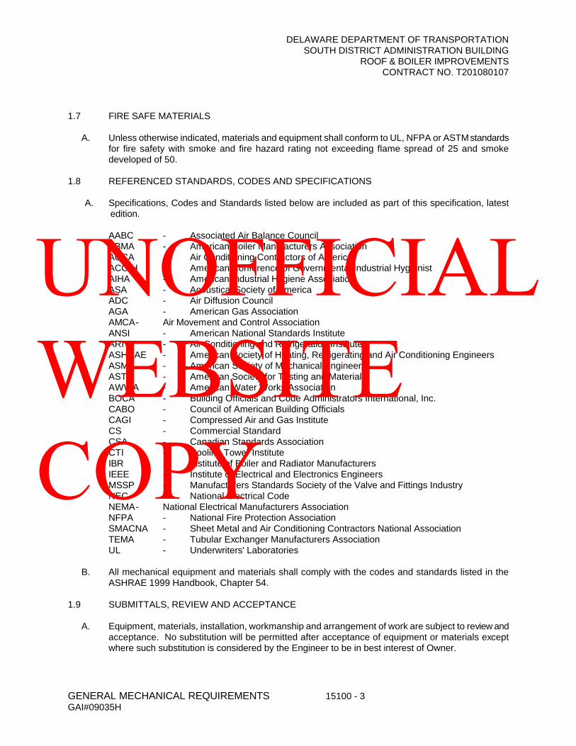
DELAWARE DEPARTMENT OF TRANSPORTATIONSOUTH DISTRICT ADMINISTRATION BUILDING
ROOF & BOILER IMPROVEMENTSCONTRACT NO. T201080107
GENERAL MECHANICAL REQUIREMENTS 15100 - 3GAI#09035H
1.7 FIRE SAFE MATERIALS
A. Unless otherwise indicated, materials and equipment shall conform to UL, NFPA or ASTMstandards for fire safety with smoke and fire hazard rating not exceeding flame spread of 25 and smoke developed of 50.
1.8 REFERENCED STANDARDS, CODES AND SPECIFICATIONS
A. Specifications, Codes and Standards listed below are included as part of this specification, latest edition.
AABC - Associated Air Balance CouncilABMA - American Boiler Manufacturers AssociationACCA - Air Conditioning Contractors of AmericaACGIH - American Conference of Governmental Industrial HygienistAIHA - American Industrial Hygiene AssociationASA - Acoustical Society of AmericaADC - Air Diffusion CouncilAGA - American Gas AssociationAMCA- Air Movement and Control AssociationANSI - American National Standards InstituteARI - Air Conditioning and Refrigeration InstituteASHRAE - American Society of Heating, Refrigerating and Air Conditioning EngineersASME - American Society of Mechanical EngineersASTM - American Society for Testing and MaterialsAWWA - American Water Works AssociationBOCA - Building Officials and Code Administrators International, Inc.CABO - Council of American Building OfficialsCAGI - Compressed Air and Gas InstituteCS - Commercial StandardCSA - Canadian Standards AssociationCTI - Cooling Tower InstituteIBR - Institute of Boiler and Radiator ManufacturersIEEE - Institute of Electrical and Electronics EngineersMSSP - Manufacturers Standards Society of the Valve and Fittings IndustryNEC - National Electrical CodeNEMA- National Electrical Manufacturers AssociationNFPA - National Fire Protection AssociationSMACNA - Sheet Metal and Air Conditioning Contractors National AssociationTEMA - Tubular Exchanger Manufacturers AssociationUL - Underwriters' Laboratories
B. All mechanical equipment and materials shall comply with the codes and standards listed in the ASHRAE 1999 Handbook, Chapter 54.
1.9 SUBMITTALS, REVIEW AND ACCEPTANCE
A. Equipment, materials, installation, workmanship and arrangement of work are subject to review and acceptance. No substitution will be permitted after acceptance of equipment or materials except where such substitution is considered by the Engineer to be in best interest of Owner.
UNOFFICIAL WEBSITE COPY

DELAWARE DEPARTMENT OF TRANSPORTATIONSOUTH DISTRICT ADMINISTRATION BUILDING
ROOF & BOILER IMPROVEMENTSCONTRACT NO. T201080107
GENERAL MECHANICAL REQUIREMENTS 15100 - 4GAI#09035H
B. Within 30 calendar days after award of contract, submit a complete Material and Equipment List for approval. Do not submit specific shop drawings until the material and equipment list is approved. List all proposed materials and equipment, indicating proposed manufacturer, type, class, model and other general identifying information.
C. After acceptance of Material and Equipment List, submit complete descriptive data for all items. Data shall consist of specifications, data sheets, samples, capacity ratings, performance curves, operating characteristics, catalog cuts, dimensional drawings, wiring diagrams, installation instructions, and any other information necessary to indicate complete compliance with Contract Documents. Edit submittal data specifically for application to this project.
D. Thoroughly review and stamp all submittals to indicate compliance with contract requirements prior to submission. Coordinate installation requirements and any electrical requirements for equipment submitted. Contractor shall be responsible for correctness of all submittals.
E. Submittals will be reviewed for general compliance with design concept in accordance with contract documents, but dimensions, quantities, or other details will not be verified.
F. Identify submittals, indicating intended application, location and service of submitted items. Refer to specification sections or paragraphs where applicable. Clearly indicate exact type, model number, style, size and special features of proposed item. Submittals of a general nature will not be acceptable. If options or accessories are not specifically crossed out, provide these options or accessories. For other than first-named items, clearly list on the first page of the submittal all differences between the specified first-named item and the proposed item. The Contractor shall be responsible for corrective action and maintaining the specification requirements if differences have not been clearly indicated in the submittal.
G. Submit actual operating conditions or characteristics for all equipment where required capacities are indicated. Factory order forms showing only required capacities will not be acceptable.
H. Acceptance will not constitute waiver of contract requirements unless deviations are specifically indicated and clearly noted.
I. For each item submitted which has an electrical connection, submit an Electrical Equipment Connection Schedule as specified in Section 16010. Failure to submit the Electrical Connection Schedule for the item submitted will result in the submittal being returned for resubmission.
J. Do not submit manufacturers or materials which have not been listed in the Specification unless it is accompanied by a substitution request listing the benefits to the Owner.
1.10 SHOP DRAWINGS
A. Prepare and submit shop drawings for all specially fabricated items, modifications to standard items, specially designed systems where detailed design is not shown on the contract drawings, or where the proposed installation differs from that shown on contract drawings.
B. Submit data and shop drawings as listed below, in addition to provisions of paragraph 1 above.Identify all shop drawings by the name of the item and system and the applicable specification paragraph number.
Items and SystemsAir Separator.Automatic Temperature Control System and Equipment.
UNOFFICIAL WEBSITE COPY

DELAWARE DEPARTMENT OF TRANSPORTATIONSOUTH DISTRICT ADMINISTRATION BUILDING
ROOF & BOILER IMPROVEMENTSCONTRACT NO. T201080107
GENERAL MECHANICAL REQUIREMENTS 15100 - 5GAI#09035H
Backflow Preventor.Breaching and Flues.Capacitors.Chemical Feed Systems.Domestic Hot Water Heater.Expansion Tanks and Accessories.Firestopping - Methods and Materials.Hot Water Boilers.Identification System.Piping, Materials, Accessories.Pressure-Reducing Valve.Pressure-Regulating Valve.Pumps, Circulators, Suction Diffusers, Multi-purpose Valves.Strainers.Thermal Insulation Materials.Thermometers and Gauges.Unit Heaters (Horizontal, Vertical and Cabinet Type).Valves - Gate, Globe, Angle, Check, Plug, Butterfly, Ball, Needle, Balance.Vibration Isolation.
C. Contractor, additionally, shall submit for approval any other shop drawings as required by the Engineer. No item listed above shall be delivered to the site, or installed, until approved. After the proposed materials have been approved, no substitution will be permitted except where approved by the Engineer.
1.11 SUPERVISION AND COORDINATION
A. Provide complete supervision, direction, scheduling, and coordination of all work under the Contract, including that of subcontractors.
B. Coordinate rough-in of all work and installation of sleeves, anchors, and supports for piping, ductwork, and other work.
C. Coordinate electrical work required.
1.12 CUTTING AND PATCHING
A. Accomplish all cutting and patching necessary for the installation of work under Division 15. Damage resulting from this work to other work already in place, shall be repaired at Contractor's expense.Where cutting is required, perform work in neat and workmanlike manner. Restore disturbed work to match and blend with existing, using materials compatible with the original. Use mechanics skilled in the particular trades required. Where existing penetrations are not being reused, patch to match existing materials finishes compatible with the original.
B. Do not cut structural members without approval. Cut rigid materials using tools which will provide a smooth and even surface; e.g., masonry saw or core drill.
1.13 PENETRATION OF WATERPROOF CONSTRUCTION
A. Coordinate the work to minimize penetration of waterproof construction, including roofs, exterior walls, and interior waterproof construction. Where such penetrations are necessary, furnish and install all necessary curbs, sleeves, flashings, fittings and caulking to make penetrations absolutely
UNOFFICIAL WEBSITE COPY

DELAWARE DEPARTMENT OF TRANSPORTATIONSOUTH DISTRICT ADMINISTRATION BUILDING
ROOF & BOILER IMPROVEMENTSCONTRACT NO. T201080107
GENERAL MECHANICAL REQUIREMENTS 15100 - 6GAI#09035H
watertight. Coordinate penetrations of waterproof construction with roofing contractor, including necessary temporary requirements to insure water tightness.
B. Where plumbing vents or other pipes penetrate roofs, flash pipe with Stoneman "Stormtite", or approved equal, roof flashing assemblies, with 4-pound lead, 6-inch skirt and caulked counterflashingsleeve similar to No. 1000-4.
C. Furnish and install pitch pockets where required.
D. Furnish and install pipe sleeves, curbs, equipment/pipe rails, vent assemblies, and duct sleeves specifically designed for application to the particular roof construction, and install in accordance with the manufacturer's instructions. The Contractor shall be responsible for sleeve sizes and locations.
E. All roof work shall be performed by a certified roofing contractor to insure the existing roof warranty is maintained.
1.14 CONNECTIONS AND ALTERNATIONS TO EXISTING WORK
A. When existing mechanical work is removed, pipes, valves, ductwork, etc., shall be removed, including hangers, to a point below finished floors or behind finished walls and capped. Such point shall be far enough behind finished surfaces to allow for installation of normal thickness of required finish material.
B. When work specified connects to existing equipment, piping, etc., Contractor shall perform all necessary alterations, cuttings, fittings, etc., of existing work as may be necessary to make satisfactory connections between new and existing work, and to leave completed work in a finished and workmanlike condition.
C When the work specified requires relocation of existing mechanical equipment, piping, ductwork, etc., Contractor shall perform all work and make necessary changes to existing work as may be required to leave completed work in a finished and workmanlike condition. Where existing insulation is disturbed, replace insulation where removed or damaged equal to existing, in type thickness and R value.
D. The Contractor shall be responsible for protecting all school property where work is being performed. The Contractor shall keep clean and maintain each area for use after work in that area is complete.
E. The project shall be phased construction. All work shall include temporary controls, systems, equipment, piping, etc., and all other materials necessary to keep exiting areas fully functional for school use. Coordinate phasing requirements and construction sequencing with the Owner in accordance with the Contract requirements.
1.15 DEMOLITION
A. Existing piping, equipment, ductwork, materials, etc., not required for re-use or re-installation in this project, shall be removed.
B. Deliver to the Owner, on the premises where directed, existing equipment and materials which are removed and which are desired by the Owner or are indicated to remain the property of the Owner. The Owner has the right of first refusal.
C. All other materials and equipment which are removed shall become property of the Contractor and shall be promptly removed, by him, from the premises, and disposed of in an approved manner.
UNOFFICIAL WEBSITE COPY

DELAWARE DEPARTMENT OF TRANSPORTATIONSOUTH DISTRICT ADMINISTRATION BUILDING
ROOF & BOILER IMPROVEMENTSCONTRACT NO. T201080107
GENERAL MECHANICAL REQUIREMENTS 15100 - 7GAI#09035H
D. Where piping and/or ductwork is removed, remove all pipe or ductwork hangers which were supporting the removed piping or ductwork.
1.16 DRIVE GUARDS
A. Provide safety guards on all exposed belt drives, motor couplings, and other rotating machinery. Provide fully enclosed guards where machinery is exposed from more than one direction.
B. Fabricate guards of heavy gauge steel, rigidly brace, removable, and finish to match equipment. served. Provide openings for tachometers. Guards shall meet O.S.H.A. and M.O.S.H.A. requirements.
1.17 VIBRATION ISOLATION
A. Furnish and install vibration isolators, flexible connections, supports, anchors and/or foundations required to prevent transmission of vibration from equipment, piping or ductwork to building structure. See Section 15975 "Vibration Isolation".
PART 2 - ELECTRICAL REQUIREMENTS
2.1 SCOPE:
A. Furnish and install control and interlock wiring for the equipment furnished. Carefully review the contract documents to coordinate the electrical work. Where the electrical requirements of the equipment furnished differ from the provisions made, make the necessary allowances. Provide disconnect switches for all fans, unit heaters, cabinet unit heaters, boiler and hot water heater burners, unit ventilators, and as specified hereinafter.
2.2 MOTORS AND CONTROLS
A. Motors and controls shall conform to the latest requirements of IEEE, NEMA, and shall be UL listed.Motor sizes are specified with the driven equipment. Motor starting and control equipment is specified either with the motor which is controlled or in an electrical specification section. The Contractor is advised to consult all specification sections to determine responsibility for motors and controls.
B. Motors shall be designed, built and tested in accordance with the latest revision of NEMA Standard MG l.
C. Motors shall be suitable for use under the conditions and with the equipment to which applied, and designed for operation on the electrical systems specified or indicated.
1. Motor capacities shall be such that the horsepower rating and the rated full-load current will not be exceeded while operating under the specified operating conditions. Under no condition shall the motor current exceed that indicated on the nameplates.
2. Motor sizes noted in the individual equipment specifications are minimum requirements only. It is the responsibility of the equipment manufacturers and of the Contractor to furnish motors, electrical circuits and equipment of ample capacity to operate the equipment without overloading, exceeding the rated full-load current, or overheating at full-load capacity under the most severe operating service of this equipment. Motors shall have sufficient torque to accelerate the total WR2 of the driven equipment to operating speed. All compressors and
UNOFFICIAL WEBSITE COPY
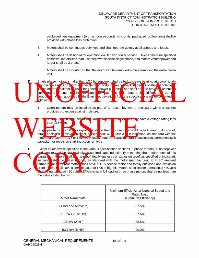
DELAWARE DEPARTMENT OF TRANSPORTATIONSOUTH DISTRICT ADMINISTRATION BUILDING
ROOF & BOILER IMPROVEMENTSCONTRACT NO. T201080107
GENERAL MECHANICAL REQUIREMENTS 15100 - 8GAI#09035H
packaged type equipment (e.g., air-cooled condensing units, packaged rooftop units) shall be provided with phase loss protection.
3. Motors shall be continuous duty type and shall operate quietly at all speeds and loads.
4. Motors shall be designed for operation on 60 hertz power service. Unless otherwise specified or shown, motors less than 2 horsepower shall be single phase, and motors 2 horsepower andlarger shall be 3 phase.
5. Motors shall be mounted so that the motor can be removed without removing the entire driven unit.
D. Single phase motors, smaller than 1/20 horsepower, shall be ball or sleeve bearing; drip-proof, totally enclosed or explosion proof, as specified; 120 volts; permanent-split capacitor or shaded pole type.These motors shall not be used for general power purposes, and shall only be provided as built-in components of such mechanical equipment as fans, unit heaters, humidifiers and damper controllers. When approved by the Engineer, deviations from the specifications will be permitted as follows:
1. Open motors may be installed as part of an assembly where enclosure within a cabinet provides protection against moisture.
2. Motors used in conjunction with low voltage control systems may have a voltage rating less than 115 volts.
E. Single phase motors 1/20 horsepower and less than 2 horsepower shall be ball bearing; drip-proof, totally enclosed or explosion proof, as specified, with Class A or B insulation, as standard with the motor manufacturer; 115 or 120/460 volts as required; capacitor start-induction run, permanent split capacitor, or repulsion start-induction run type.
F. Except as otherwise specified in the various specification sections, 3 phase motors 60 horsepower and smaller shall be NEMA design B squirrel cage induction type meeting the requirements of this paragraph. Motors shall be drip-proof, totally enclosed or explosion proof, as specified or indicated; insulation shall be Class B or F, as standard with the motor manufacturer; at 40EC ambient temperature drip-proof motors shall have a 1.15 service factor and totally enclosed and explosion proof motors shall have a service factor of 1.00 or higher. Motors specified for operation at 480 volts shall be nameplated 460 volts. Efficiencies at full load for three phase motors shall be not less than the values listed below:
Motor Nameplate
Minimum Efficiency at Nominal Speed and Rated Load
(Premium Efficiency)
.74 kW and above to) 87.5%
1.1 kW (1-1/2 HP) 87.5%
1.5 kW (2 HP) 88.5%
53.7 kW (5 HP) 90.0%
UNOFFICIAL WEBSITE COPY
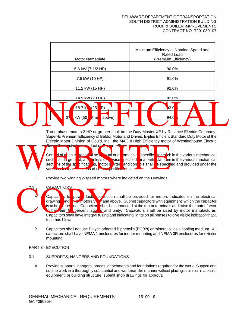
DELAWARE DEPARTMENT OF TRANSPORTATIONSOUTH DISTRICT ADMINISTRATION BUILDING
ROOF & BOILER IMPROVEMENTSCONTRACT NO. T201080107
GENERAL MECHANICAL REQUIREMENTS 15100 - 9GAI#09035H
Motor Nameplate
Minimum Efficiency at Nominal Speed and Rated Load
(Premium Efficiency)
5.6 kW (7-1/2 HP) 90.0%
7.5 kW (10 HP) 91.0%
11.2 kW (15 HP) 92.0%
14.9 kW (20 HP) 92.0%
18.7 kW (25 HP) 93.0%
37.3 kW (50 HP and above) 94.0%
Three phase motors 2 HP or greater shall be the Duty Master XE by Reliance Electric Company, Super-E Premium Efficiency of Baldor Motor and Drives, E-plus Efficient Standard Duty Motor of the Electric Motor Division of Gould, Inc., the MAC II High Efficiency motor of Westinghouse Electric Corp., the equivalent product of General Electric, or equal.
G. Control of each motor shall be manual or automatic as specified for each in the various mechanical sections. In general, and unless otherwise specified for a particular item in the various mechanical sections of the specifications, motor starters and controls shall be specified and provided under the various electrical sections of these specifications.
H. Provide two winding 2-speed motors where indicated on the Drawings.
2.3 CAPACITORS
A. Capacitors for power factor correction shall be provided for motors indicated on the electrical drawings and on all motors 3 HP and above. Submit capacitors with equipment which the capacitor is to be connected. Capacitors shall be connected at the motor terminals and raise the motor factor to between 95 percent lagging and unity. Capacitors shall be sized by motor manufacturer. Capacitors shall have integral fusing and indicating lights on all phases to give visible indication that a fuse has blown.
B. Capacitors shall not use Polychlorinated Biphenyl's (PCB’s) or mineral oil as a cooling medium. All capacitors shall have NEMA 1 enclosures for indoor mounting and NEMA 3R enclosures for exterior mounting.
PART 3 - EXECUTION
3.1 SUPPORTS, HANGERS AND FOUNDATIONS
A. Provide supports, hangers, braces, attachments and foundations required for the work. Support and set the work in a thoroughly substantial and workmanlike manner without placing strains on materials, equipment, or building structure, submit shop drawings for approval.
UNOFFICIAL WEBSITE COPY
DELAWARE DEPARTMENT OF TRANSPORTATIONSOUTH DISTRICT ADMINISTRATION BUILDING
ROOF & BOILER IMPROVEMENTSCONTRACT NO. T201080107
GENERAL MECHANICAL REQUIREMENTS 15100 - 10GAI#09035H
B. Supports, hangers, braces, and attachments shall be standard manufactured items or fabricated structural steel shapes. All interior hangers shall be galvanized or steel with rust inhibiting paint. For uninsulated copper piping provide copper hanger to prevent contact of dissimilar metals. All exterior hangers shall be constructed of galvanized steel utilizing galvanized rods, nuts, washers, bolts, etc.
3.2 PROVISIONS FOR ACCESS
A. The Contractor shall provide access panels and doors for all concealed equipment, valves, strainers, dampers, filters, controls, control devices, cleanouts, fire dampers, damper operators, traps, and other devices requiring maintenance, service, adjustment, balancing or manual operation.
B. Where access doors are necessary, furnish and install manufactured painted steel door assemblies consisting of hinged door, key locks, and frame designed for the particular wall or ceiling construction. Properly locate each door. Door size shall be a minimum of 24" x 24". Provide UL approved access doors where installed in fire-rated walls or ceilings. Doors shall be Milcor Metal Access Doors as manufactured by Inland-Ryerson, or approved equal.
1. Acoustical or Cement Plaster: Style B2. Hard Finish Plaster: Style K or L3. Masonry or Dry Wall: Style M
C. Where access is by means of liftout ceiling tiles or panels, mark each panel using small color-coded or numbered tabs. Provide a chart or index for identification. Place markers in corner of tile.
D. Access panels, doors, etc., described herein shall be furnished under the section of specifications providing the particular service to be turned over to the pertinent trade for installation. Coordinate installation with installing contractor. All access doors shall be painted in baked enamel finish to match ceiling or wall finish.
3.3 CLEANING, PAINTING AND FINISHES
A. Provide protective finishes on all materials and equipment. Use coated or corrosion-resistant materials, hardware and fittings throughout the work. Paint bare, untreated ferrous surfaces with rust-inhibiting paint. All exterior components including supports, hangers, nuts, bolts, washers, vibration isolators, etc., shall be galvanized or stainless steel.
B. Clean surfaces prior to application of insulation, adhesives, coatings, paint, or other finishes.
C. Provide factory-applied finishes where specified. Unless otherwise indicated factory-applied paints shall be baked enamel with proper pretreatment.
D. Protect all finishes and restore any finishes damaged (as a result of work done) to their original condition.
E. The preceding requirements apply to all work, whether exposed or concealed.
F. Remove all construction marking and writing from exposed equipment, ductwork, piping and building surfaces. Do not paint manufacturer's labels or tags.
3.4 COLOR SELECTION
A. Color of finishes shall be as selected by the Owner.
UNOFFICIAL WEBSITE COPY
DELAWARE DEPARTMENT OF TRANSPORTATIONSOUTH DISTRICT ADMINISTRATION BUILDING
ROOF & BOILER IMPROVEMENTSCONTRACT NO. T201080107
GENERAL MECHANICAL REQUIREMENTS 15100 - 11GAI#09035H
B. Submit color of factory-finished equipment for acceptance prior to ordering.
C. All exposed finishes for materials and equipment shall be custom colors as selected by the Engineer.
D. All gas piping shall be painted yellow. All sprinkler piping shall be painted red.
3.5 PROTECTION OF WORK
A. Protect work, material and equipment from weather and construction operations before and after installation. Properly store and handle all materials and equipment.
B. Cover temporary openings in piping, ductwork, and equipment to prevent the entrance of water, dirt, debris, or other foreign matter.
C. Cover or otherwise protect all finishes.
D. Replace damaged materials, devices, finishes and equipment.
E. The owner shall be given opportunity to inspect all new equipment, piping, ductwork, etc., before covering up or concealing.
3.6 OPERATION OF EQUIPMENT
A. Clean all systems and equipment prior to initial operation for testing, balancing, or other purposes.Lubricate, adjust, and test all equipment in accordance with manufacturer's instructions. Do not operate equipment unless all proper safety devices or controls are operational. Provide all maintenance and service for equipment that is authorized for operation during construction.
B. Where specified, or otherwise required, provide the services of the manufacturer's factory-trained servicemen or technicians to start up the equipment.
C. Do not use mechanical systems for temporary services during construction unless authorized in writing by the Engineer. Where such authorization is granted, temporaryuse of equipment shall in no way limit or otherwise affect warranties or guaranty period of the work.
D. Upon completion of work, clean and restore all equipment to new conditions; replace expendable items such as filters.
3.7 IDENTIFICATIONS, FLOW DIAGRAMS, ELECTRICAL DIAGRAMS AND OPERATING INSTRUCTIONS:
A. All valves being replaced shall be provided with new valve tags to match the existing number, or be provided with a new number if an existing number is available. All new valves shall be tagged and a composite valve tag chart shall be provided. Locate valve tag chart in the existing Boiler Room.
B. All items of equipment, including motor starters, shall be furnished with white on black plastic identification cards. Replace and/or provide cards for all existing equipment.
C. Provide three (3) copies of operating and maintenance instructions for all principal items of equipment furnished. This material shall be bound as a volume of the "Record and Information Booklet" as hereinafter specified.
UNOFFICIAL WEBSITE COPY
DELAWARE DEPARTMENT OF TRANSPORTATIONSOUTH DISTRICT ADMINISTRATION BUILDING
ROOF & BOILER IMPROVEMENTSCONTRACT NO. T201080107
GENERAL MECHANICAL REQUIREMENTS 15100 - 12GAI#09035H
D. All lines (piping and ductwork) installed under this contract shall be stenciled with "direction of flow" arrows and with stenciled letters naming each pipe and ductwork and service. Refer to Section 15200, "Piping, Etc."
E. Provide at least 8 hours of straight time instruction to the operating personnel. This instruction period shall consist of not less than two (2) consecutive 4 hour days. Time of instruction shall be designated by the Owner. Additional instruction time for the Automatic Temperature Control (ATC) and Energy Management System (EMS) is specified in Section 15850 Automatic Temperature Controls.
F. Contractor shall demonstrate Sequences of Operation of all equipment in presence of Owner’s representative, Engineer, and ATC subcontractor. The ATC Contractor shall provide a commissioning checklist to the Owner and Engineer for all operating sequences and I/O Summary at the Demonstration. The Owner/Engineer will sign off on all items that are complete and functioning. The checklist will be ongoing until all items are completed and the system is functioning as designed.
3.8 WALL AND FLOOR PENETRATION
A. All penetrations of partitions, ceilings, and floors by ducts, piping or conduit shall be sealed and caulked airtight for sound and air transfer control. Penetrations of mechanical room partitions, ceilings, and floors shall be as specified in Section 15975 Vibration Control.
B. All penetration of fire rated assemblies shall be sealed, caulked and protected to maintain the rating of the wall, roof, or floor. Fire Marshal approved UL assemblies shall be utilized.
3.9 RECORD DRAWINGS
A. Upon completion of the mechanical installations, the Contractor shall deliver to the Engineer one complete set of prints of the mechanical contract drawings that shall be legibly marked in red pencil to show all changes and departures of the installation as compared with the original design. They shall be suitable for use in preparation of Record Drawings.
3.10 GUARANTEE
A. Contractor's attention is directed to guarantee obligations contained in the GENERAL CONDITIONS.
B. The above shall not in any way void or abrogate equipment manufacturer's guarantee or warranty.Certificates of guarantee shall be included in the operations and maintenance manuals.
C. Contractor shall also provide two (2) years free service from the time of final acceptance to keep the equipment in operating condition. This service shall be rendered upon request when notified of any equipment malfunctions. All compressors for mechanical refrigeration shall be provided with a 5-year parts and labor warranty.
3.11 LUBRICATION
A. All bearings, motors, and all equipment requiring lubrication shall be provided with accessible fittings for same. Before turning over the equipment to the Owner, the Contractor shall fully lubricate each item of equipment, shall provide one year's supply of lubricant for each, and shall provide Owner with complete written lubricating instructions, together with diagram locating the points requiring lubrication. Include this information in the Record and Information Booklet.
B. In general, all motors and equipment shall be provided with grease lubricated roller or ball bearings with Alemite or equal accessible or extended grease fittings and drain plugs.
UNOFFICIAL WEBSITE COPY
DELAWARE DEPARTMENT OF TRANSPORTATIONSOUTH DISTRICT ADMINISTRATION BUILDING
ROOF & BOILER IMPROVEMENTSCONTRACT NO. T201080107
GENERAL MECHANICAL REQUIREMENTS 15100 - 13GAI#09035H
3.12 RECORD AND INFORMATION BOOKLET
A. The Contractor shall have prepared three (3) copies of the Record and Information Booklet and deliver these copies of the booklet to the Owner. The booklet shall be as specified herein. The booklet must be approved and will not be accepted as final until so stamped.
B. The booklet shall be bound in a three-ring loose-leaf binder similar to "National" No. 3881 with the following title lettered on the front: "Record and Information Booklet – Pine Grove Elementary School". No sheets larger than 8-1/2" x 11" shall be used, except sheets that maybe neatly folded to 8-1/2" x 11" and used as a pull-out.
C. Provide the following data in the booklet:
1. As first entry, an approved letter indicating the starting/ending time of warranty period.2. Manufacturer's and Contractors' guarantees3. Maintenance operation and lubrication instructions on each piece of equipment furnished.4. Complete catalog data on each piece of heating and air conditioning equipment furnished
including approved shop drawing.5. Chart form indicating time and type routine maintenance of rooftop units, pumps. The chart
shall also indicate model number of equipment, location and service.6. Provide sales and service representatives names and phone numbers of all equipment and
subcontractors.7. Catalog data of all equipment, valves, etc., shall include wiring diagrams, parts list and
assembly drawing.8. Provide valve chart including valve tag number, valve type, valve model number, valve
manufacturer, style, service and location.9. Copy of the approved Test and Balancing Report.10. ATC systems including as-built ATC drawings of systems including internal of all panels.11. Access panel charts or index.12. Provide lubrication information as indicated in paragraph 3.11.13. Wiring diagrams for each piece of equipment.
3.13 TESTS, GENERAL
A. The new piping systems shall be tested hydrostatically before insulation covering is applied and proved tight under the following gauge pressures for a duration of two (2) hours:
Domestic Water Piping 100 psiHeating Water Piping (Supply and Return) 100 psiGas Piping/Fuel Piping 100 psi
B. All storm, waste, vent and water piping shall be tested by the Contractor and approved by the Engineer before acceptance. All storm, soil, and waste piping, located underground, shall be tested before backfilling. The costs of all equipment required for tests are to be included under the contract price.
C. The entire new drainage system and venting system shall have all necessary openings plugged and filled with water to the level of the highest stack above or at the roof. The system shall hold this water for thirty (30) minutes without showing a drop greater than 1". Where a portion of the system is to be tested, the test shall be conducted in the same manner as described for the entire system, except a vertical stack 10 feet above the highest horizontal line to be tested may be installed and filled with
UNOFFICIAL WEBSITE COPY

DELAWARE DEPARTMENT OF TRANSPORTATIONSOUTH DISTRICT ADMINISTRATION BUILDING
ROOF & BOILER IMPROVEMENTSCONTRACT NO. T201080107
GENERAL MECHANICAL REQUIREMENTS 15100 - 14GAI#09035H
water to maintain sufficient pressure, or a pump may be used to supply the required pressure. The pressure shall be maintained for thirty (30) minutes.
D. Upon completion of roughing-in and before setting fixtures, the entire new water piping system shall be tested at a hydrostatic pressure of not less than one hundred (100) pounds per square inch gauge and proved tight at this pressure. Where a portion of the water piping system is to be concealed before completion, this portion shall be tested separately in a manner described for the entire system.
E. All testing shall be witnessed by the Baltimore County Construction Department. The Contractor shall provide a minimum of 48 hours notice before testing. The Contractor shall coordinate with and get approval from the Baltimore County Public Schools Construction Department.
F. Gas Testing:
1. Before any section of a gas piping system is put into service, it shall be carefully tested to assure that it is gastight. Prior to testing, the system shall be blown out, cleaned, and cleared of all foreign material. Each joint shall be tested by means of an approved gas detector, soap and water, or an equivalent nonflammable solution. Testing shall be completed before any work is covered, enclosed, or concealed. All testing of piping system shall be done with due regard for the safety of employees and the public during the test. All testing and purging shall comply with BGE requirements. Bulkheads, anchorage and bracing suitably designed to resist test pressures shall be installed if necessary. Oxygen shall not be used as a testing medium.
2. Pressure Tests: Before appliances are connected, piping systems shall be filled with air or an inert gas and shall withstand a minimum pressure of 3 pounds gauge for a period of not less than 10 minutes as specified in NFPA 54 without showing any drop in pressure. Oxygen shall not be used. Pressure shall be measured with a mercury manometer, slope gauge, or an equivalent device so calibrated as to be read in increments of not greater than 0.1 pound. The source of pressure shall be isolated before the pressure tests are made.
3. Test with Gas: Before turning gas under pressure into any piping, all openings from which gas can escape shall be closed. Immediately after turning on the gas, the piping system shall be checked for leakage by using a laboratory-certified gas meter, an appliance orifice, a manometer, or equivalent device. All testing shall conform to the requirements of NFPA 54. If leakage is recorded, the gas supply shall be shut off, the leak shall be repaired, and the tests repeated until all leaks have been stopped.
4. Purging: After testing is completed, and before connecting any appliances, all gas piping shall be fully purged. Piping shall not be purged into the combustion chamber of an appliance. The open end of piping systems being purged shall not discharge into confined spaces or areas where there are ignition sources unless the safety precautions recommended in NFPA 54 are followed.
5. Labor, Materials, and Equipment: All labor, materials, and equipment necessary for conducting the testing and purging shall be furnished by the Contractor.
3.14 FILTERS
A. Provide one (1) set of clean filters for balancing. One complete set of additional filters shall be turned over to the Owner upon final acceptance of the building by the Owner. Provide correspondence documenting that additional filters have been turned over to Owner.
3.15 WIRING DIAGRAMS
A. The Contractor is responsible for obtaining and submitting wiring diagrams for all major items of equipment, installed under this contract.
UNOFFICIAL WEBSITE COPY
DELAWARE DEPARTMENT OF TRANSPORTATIONSOUTH DISTRICT ADMINISTRATION BUILDING
ROOF & BOILER IMPROVEMENTSCONTRACT NO. T201080107
GENERAL MECHANICAL REQUIREMENTS 15100 - 15GAI#09035H
B. Wiring diagrams shall be provided with shop drawings for similar to, but not limited to, the following:
1. All Mechanical Equipment.2. ATC System.
C. The Contractor shall submit any additional wiring diagrams as requested by the Engineer.
D. Provide wiring diagrams for all mechanical items of equipment to Electrical Contractor and ATC Subcontractor for coordination.
3.16 SCHEDULING OF WORK AND OUTAGES
A. The Contractor shall not be permitted to do any work in occupied areas during occupied periods, except in the area specifically assigned. Work in these areas shall be performed at night, during the weekend or holidays, as coordinated with and approved by the Owner.
B. All required outages shall be coordinated with and approved by the Owner a minimum of fourteen (14) days in advance. Written notice of not less than fourteen (14) calendar days shall precede any outage. The Contractor shall include in their bid outages and/or work in occupied areas to occur during weekends, holidays, or at night.
C. All temporary utilities shall be provided by and paid for by the Contractor. All utilities serving the existing building(s) shall be maintained; or temporary piping, equipment, etc., shall be provided so as not to affect the normal function and operation of the building and its systems. Coordinate these requirements with the Owner.
3.17 LINTELS
A. Under this Section, provide lintels not provided elsewhere which are required for openings for the installation of mechanical and plumbing work. Lintels shall meet the requirements of the Architectural and Structural Sections and The Architectural Drawings and Specifications.
3.18 EQUIPMENT BY OTHERS
A. This Contractor shall make all system connections required to equipment furnished and installed. Connections shall be complete in all respects to render this equipment functional to its fullest intent.
B. It shall be the responsibility of the supplier of this equipment to furnish complete instructions for connections. Failure to do so will relieve this Contractor of any responsibility for improper equipment operation.
3.19 LOUVERS AND VENTS
A. Louver shop drawings shall be submitted to the Engineer to verify sizes and free area requirements. The Contractor shall blank-off unused portions of louver with insulated blank-off panels.
3.20 FASTENERS
UNOFFICIAL WEBSITE COPY

DELAWARE DEPARTMENT OF TRANSPORTATIONSOUTH DISTRICT ADMINISTRATION BUILDING
ROOF & BOILER IMPROVEMENTSCONTRACT NO. T201080107
GENERAL MECHANICAL REQUIREMENTS 15100 - 16GAI#09035H
A. All fasteners located in public space, including classrooms, offices, etc., shall be provided with tamper-proof type fasteners.
3.21 INSTALLATION AND COORDINATION DRAWINGS
A. Prepare, submit, and use composite installation and coordination drawings to assure proper coordination and installation of work. Drawings shall include, but not be limited, to the following: Complete Plumbing, and HVAC Piping Drawings showing coordination with approved equipment, approved casework drawings, lights, electrical equipment and structural for the Boiler Room.
B. Draw plans to a scale not less than 3/8-inch equals one foot. Include plans, sections, and elevations of proposed work, showing all equipment, piping and ductwork in areas involved. Fully dimension all workincluding associated utilities, valve boxes, lighting fixtures, conduits, pullboxes, panelboards, and other electrical work, telecommunications equipment, walls, doors, ceilings, columns, beams, joists and other architectural and structural work.
C. Identify all equipment and devices on wiring diagrams and schematics. Where field connections are shown to factory-wired terminals, include manufacturer's literature showing internal wiring.
3.22 BELT GUARDS/CAGES
A. Provide safety guards on all exposed belt drives, motor couplings, and other rotating machinery (pump coupling, plenum fans, propeller fans, etc.) Provide fully enclosed guards where machinery is exposed from more than one direction.
B. Fabricate guards of heavy gauge steel, rigidly braced, removable, and finished to match equipment served. Provide openings for tachometers. Guards shall meet OSHA and MOSHA requirements.
3.23 BOILER AND PRESSURE VESSELS
A. All boilers and pressure vessels shall be ASME-rated and shall comply with the State of DelawareBoiler and Pressure Vessel Safety Act and Regulations – latest edition.
B. Provide all control devices and materials, and install in with ASME CSD-1 controls and safety devices for automatically fired boilers.
C. Provide integral disconnect switches for all burners (i.e., boilers and hot water heater).
3.24 FACTORY START-UP
A. Provide factory authorized start-up service for all mechanical equipment (e.g., boilers, variable speed drives, air handling units, etc.).
B. Provide one copy of all start-up reports to the Owner and include a copy in the O&M Manual.
END OF SECTION 15100
UNOFFICIAL WEBSITE COPY

DELAWARE DEPARTMENT OF TRANSPORTATIONSOUTH DISTRICT ADMINISTRATION BUILDING
ROOF & BOILER IMPROVEMENTSCONTRACT NO. T201080107
MECHANICAL FIRESTOPPING 15150 - 1GAI#09035H
SECTION 15150 – MECHANICAL FIRESTOPPING
PART 1 - GENERAL
1.1 SUMMARY
A. Section includes:
1. Through-penetration firestopping in fire-rated construction.2. Through-penetration smoke-stopping in smoke partitions.
B. Related Documents:1. Drawings, General and Supplementary Provisions of the contract, including but not limited to
Section 100 of the DelDOT Standard Specifications for Road and Bridge Construction apply to this section.
2. Fire dampers and manufactured devices: Refer to Section 15700.
1.2 REFERENCES
A. Underwriters Laboratories
1. UL Fire Resistance Directory
a. Through-penetration firestop devices (XHCR)b. Fire resistance rating (BXUV)c. Through-penetration firestop systems (XHEZ)d. Fill, void, or cavity material (XHHW)
B. American Society for Testing and Materials Standards: ASTM E 814-88: Standard Test Method for Fire Tests of Through-Penetration Firestops.
1.3 DEFINITIONS
A. Assembly: Particular arrangement of materials specific to given type of construction described or detailed in referenced documents.
B. Barriers: Time rated fire walls, smoke barrier walls, time rated ceiling/floor assemblies and structural floors.
C. Firestopping: Methods and materials applied in penetrations and unprotected openings to limit spread of heat, fire, gasses and smoke.
D. Penetration: Opening or foreign material passing through or into barrier or structural floor such that full thickness of rated materials is not obtained.
E. System: Specific products and applications, classified and numbered by Underwriters Laboratories, Inc. to close specific barrier penetrations.
F. Sleeve: Metal fabrication or pipe section extended through thickness of barrier and used to permanently guard penetration. Sleeves are described as part of penetrating system in other sections and may or may not be required.
UNOFFICIAL WEBSITE COPY

DELAWARE DEPARTMENT OF TRANSPORTATIONSOUTH DISTRICT ADMINISTRATION BUILDING
ROOF & BOILER IMPROVEMENTSCONTRACT NO. T201080107
MECHANICAL FIRESTOPPING 15150 - 2GAI#09035H
1.4 SYSTEM DESCRIPTION
A. Design Requirements
1. Fire-rated construction: Maintain barrier and structural floor fire resistance ratings including resistance to cold smoke at all penetrations.
2. Smoke barrier construction: Maintain barrier and structural floor resistance to cold smoke at all penetrations.
1.5 SUBMITTALS
A. Product data: Manufacturer's specifications and technical data including the following:
1. Detailed specification of construction and fabrication.2. Manufacturer's installation instructions.
B. Shop drawings: Indicate dimensions, description of materials and finishes, general construction, specific modifications, component connections, anchorage methods, hardware, and installation procedures, plus the following specific requirements.
1. Details of each proposed assembly identifying intended products and applicable UL system number, or UL classified devices.
2. Manufacturer or manufacturer's representative shall provide qualified engineering judgment and drawings relating to non-standard applications as needed.
C. Quality control submittals:
1. Statement of qualifications.
D. Applicators' qualifications statement:
1. List past projects indicating required experience.
1.6 QUALITY ASSURANCE
A. Installer's qualifications: Fire experienced in installation or application of systems similar in complexity to those required for this project, plus the following:
1. Acceptable to or licensed by manufacturer, State or local authority where applicable.2. At least 2 years experience with systems.3. Successfully completed at least 5 comparable scale projects using this system.
B. Local and State regulatory requirements: Submit forms or acceptance for proposed assemblies not conforming to specific UL Firestop System numbers, or UL classified devices.
C. Materials shall have been tested to provide fire rating at least equal to that of the construction.
1.7 DELIVERY, STORAGE, AND HANDLING
A. Packing and shipping:
1. Deliver products in original unopened packaging with legible manufacturer's identification.2. Coordinate delivery with scheduled installation date, allow minimum storage at site.
UNOFFICIAL WEBSITE COPY

DELAWARE DEPARTMENT OF TRANSPORTATIONSOUTH DISTRICT ADMINISTRATION BUILDING
ROOF & BOILER IMPROVEMENTSCONTRACT NO. T201080107
MECHANICAL FIRESTOPPING 15150 - 3GAI#09035H
B. Storage and protection: Store materials in a clean, dry, ventilated location. Protect from soiling, abuse, moisture and freezing when required. Follow manufacturer's instructions.
1.8 PROJECT CONDITIONS
A. Existing condition:
1. Verify existing conditions and substrates before starting work. Correct unsatisfactory conditions before proceeding.
2. Proceed with installation only after penetrations of the substrate and supporting brackets have been installed.
B. Environmental requirements:
1. Furnish adequate ventilation if using solvent.2. Furnish forced air ventilation during installation if required by manufacturer.3. Keep flammable materials away from sparks or flame.4. Provide masking and drop cloths to prevent contamination of adjacent surfaces by
firestopping materials.
1.9 GUARANTEE
A. Submit copies of written guarantee agreeing to repair or replace joint sealers which fall in joint adhesion, extrusion resistance, migration resistance, or general durability or appear to deteriorate in any other manner not clearly specified by submitted manufacturer's data as an inherent quality of the material for the exposure indicated. The guarantee period shall be two year from date of substantial completion unless otherwise noted.
PART 2 - PRODUCT
2.1 THROUGH-PENETRATION FIRESTOPPING OF FIRE-RATED CONSTRUCTION
A. Systems of devices listed in the UL Fire Resistance Directory under categories XHCR and XHEZ may be used, providing that it conforms to the construction type, penetrant type, annular space requirements and fire rating involved in each separate instance, and that the system be symmetrical for wall applications. Systems or devices must be asbestos-free.
1. Additional requirements: Withstand the passage of cold smoke either as an inherent property of the system, or by the use of a separate product included as a part of the UL system or device, and designed to perform this function.
2. Acceptable manufacturers and products: Those listed in the UL Fire Resistance directory for the UL System involved and as further defined in the System and Applications Schedulein Part 3.6 of this section.
3. All firestopping products must be from a single manufacturer. All trades shall use products from the same manufacturer unless otherwise noted.
2.2 SMOKE-STOPPING AT SMOKE PARTITIONS
A. Through-penetration smoke-stopping: Any system complying with the requirements for through-penetration firestopping in fire-rated construction, as specified in The Systems and Applications Schedule in Part 3.6 of this section, is acceptable, provided that the system includes the specified
UNOFFICIAL WEBSITE COPY
DELAWARE DEPARTMENT OF TRANSPORTATIONSOUTH DISTRICT ADMINISTRATION BUILDING
ROOF & BOILER IMPROVEMENTSCONTRACT NO. T201080107
MECHANICAL FIRESTOPPING 15150 - 4GAI#09035H
smoke seal or will provide a smoke seal. The length of time of the fire resistance may be disregarded.
2.3 ACCESSORIES
A. Fill, void or cavity materials: As classified under category XHHW in the UL Fire Resistance Directory.
B. Forming materials: As classified under category XHKU in the UL Fire Resistance Directory.
PART 3 - EXECUTION
3.1 EXAMINATION
A. Verification of conditions: Examine areas and conditions under which work is to be performed and identify conditions detrimental to proper or timely completion.
1. Verify barrier penetrations are properly sized and in suitable condition for application of materials.
2. Do not proceed until unsatisfactory conditions have been corrected.
3.2 PREPARATION
A. Clean surfaces to be in contact with penetration seal materials of dirt, grease, oil, loose materials, rust, or other substances that may affect proper fitting, adhesion, or the required fire resistance.
3.3 INSTALLATION
A. Install penetration seal materials in accordance with printed instructions of the UL Fire Resistance Directory and in accordance with manufacturer's instruction.
B. Seal holes or voids made by penetrations to ensure an effective smoke barrier.
C. Protect materials from damage on surfaces subject to traffic.
D. When large openings are created in walls or floors to permit installation of pipes, ducts, or other items, close unused portions of opening with firestopping materials tested for the application. See UL Fire Resistance Directory or Section 3.6 of this document.
E. Where rated walls are constructed with horizontally continuous air space, double width masonry, or double stud frame construction, provide vertical, 12 inch wide fiber dams for full thickness and height of air cavity at maximum 15 foot intervals.
F. Install smoke stopping as specified for firestopping.
3.4 FIELD QUALITY CONTROL
A. Examine penetration sealed areas to ensure proper installation before concealing or enclosing areas.
B. Keep areas of work accessible until inspection by applicable code authorities.
C. Perform under this section patching and repairing of firestopping caused by cutting or penetration by other trades.
UNOFFICIAL WEBSITE COPY
DELAWARE DEPARTMENT OF TRANSPORTATIONSOUTH DISTRICT ADMINISTRATION BUILDING
ROOF & BOILER IMPROVEMENTSCONTRACT NO. T201080107
MECHANICAL FIRESTOPPING 15150 - 5GAI#09035H
3.5 ADJUSTING AND CLEANING
A. Clean up spills of liquid components.
B. Neatly cut and trim materials as required
C. Remove equipment, materials and debris, leaving area in undamaged, clean condition.
3.6 SYSTEMS AND APPLICATION SCHEDULES*
SEE NEXT PAGE
UNOFFICIAL WEBSITE COPY
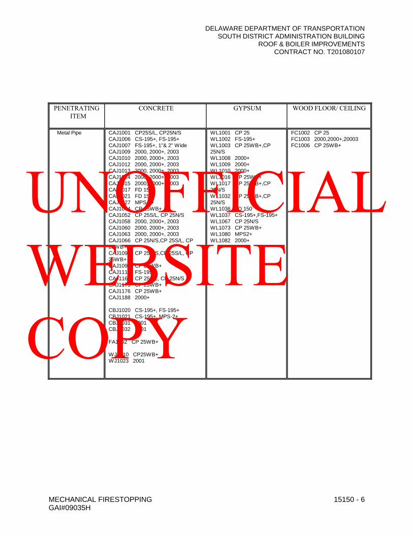
DELAWARE DEPARTMENT OF TRANSPORTATIONSOUTH DISTRICT ADMINISTRATION BUILDING
ROOF & BOILER IMPROVEMENTSCONTRACT NO. T201080107
MECHANICAL FIRESTOPPING 15150 - 6GAI#09035H
PENETRATING ITEM
CONCRETE GYPSUM WOOD FLOOR/ CEILING
Metal Pipe CAJ1001 CP25S/L, CP25N/SCAJ1006 CS-195+, FS-195+CAJ1007 FS-195+, 1"& 2" WideCAJ1009 2000, 2000+, 2003CAJ1010 2000, 2000+, 2003CAJ1012 2000, 2000+, 2003CAJ1013 2000, 2000+, 2003CAJ1014 2000, 2000+, 2003CAJ1015 2000, 2000+, 2003CAJ1017 FD 150CAJ1021 FD 150CAJ1027 MPS-2+CAJ1044 CP 25WB+CAJ1052 CP 25S/L, CP 25N/SCAJ1058 2000, 2000+, 2003CAJ1060 2000, 2000+, 2003CAJ1063 2000, 2000+, 2003CAJ1066 CP 25N/S,CP 25S/L, CP 25WB+CAJ1091 CP 25N/S,CP 25S/L, CP 25WB+CAJ1092 CP 25WB+CAJ1112 FS-195+CAJ1160 CP 25S/L, CP 25N/SCAJ1175 CP 25WB+CAJ1176 CP 25WB+CAJ1188 2000+
CBJ1020 CS-195+, FS-195+CBJ1021 CS-195+, MPS-2+CBJ1031 2001CBJ1032 2001
FA1002 CP 25WB+
WJ1010 CP25WB+WJ1023 2001
WL1001 CP 25WL1002 FS-195+WL1003 CP 25WB+,CP 25N/SWL1008 2000+WL1009 2000+WL1010 2000+WL1016 CP 25WB+WL1017 CP 25WB+,CP 25N/SWL1032 CP 25WB+,CP 25N/SWL1036 FD 150WL1037 CS-195+,FS-195+WL1067 CP 25N/SWL1073 CP 25WB+WL1080 MPS2+WL1082 2000+
FC1002 CP 25FC1003 2000,2000+,20003FC1006 CP 25WB+
UNOFFICIAL WEBSITE COPY
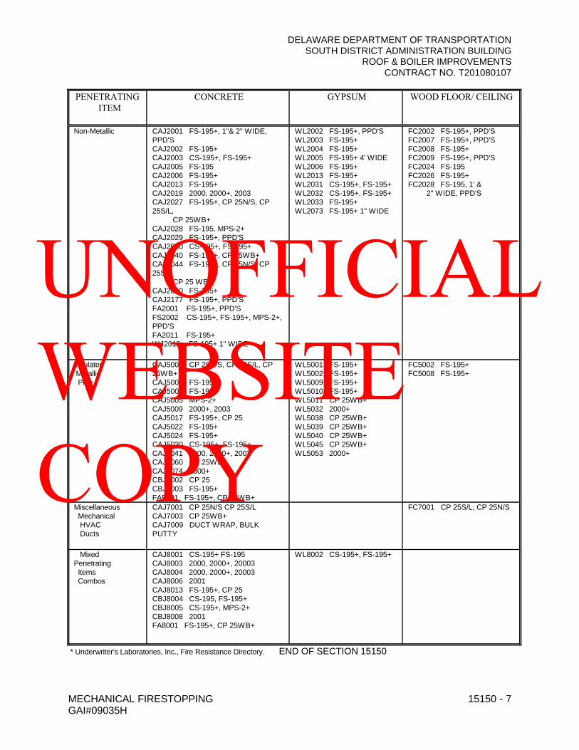
DELAWARE DEPARTMENT OF TRANSPORTATIONSOUTH DISTRICT ADMINISTRATION BUILDING
ROOF & BOILER IMPROVEMENTSCONTRACT NO. T201080107
MECHANICAL FIRESTOPPING 15150 - 7GAI#09035H
PENETRATING ITEM
CONCRETE GYPSUM WOOD FLOOR/ CEILING
Non-Metallic CAJ2001 FS-195+, 1"& 2" WIDE, PPD'SCAJ2002 FS-195+CAJ2003 CS-195+, FS-195+CAJ2005 FS-195CAJ2006 FS-195+CAJ2013 FS-195+CAJ2019 2000, 2000+, 2003CAJ2027 FS-195+, CP 25N/S, CP 25S/L,
CP 25WB+CAJ2028 FS-195, MPS-2+CAJ2029 FS-195+, PPD'SCAJ2030 CS-195+, FS-195+CAJ2040 FS-195+, CP 25WB+CAJ2044 FS-195+, CP 25N/S, CP 25S/L
CP 25 WB+CAJ2090 FS-195+CAJ2177 FS-195+, PPD'SFA2001 FS-195+, PPD'SFS2002 CS-195+, FS-195+, MPS-2+, PPD'SFA2011 FS-195+WJ2012 FS-195+ 1" WIDE
WL2002 FS-195+, PPD'SWL2003 FS-195+WL2004 FS-195+WL2005 FS-195+ 4' WIDEWL2006 FS-195+WL2013 FS-195+WL2031 CS-195+, FS-195+WL2032 CS-195+, FS-195+WL2033 FS-195+WL2073 FS-195+ 1" WIDE
FC2002 FS-195+, PPD'SFC2007 FS-195+, PPD'SFC2008 FS-195+FC2009 FS-195+, PPD'SFC2024 FS-195FC2026 FS-195+FC2028 FS-195, 1' &
2" WIDE, PPD'S
InsulatedMetallic Pipe
CAJ5001 CP 25N/S, CP 25S/L, CP 25WB+CAJ5002 FS-195+CAJ5003 FS-195+CAJ5005 MPS-2+CAJ5009 2000+, 2003CAJ5017 FS-195+, CP 25CAJ5022 FS-195+CAJ5024 FS-195+CAJ5030 CS-195+, FS-195+CAJ5041 2000, 2000+, 2003CAJ5060 CP 25WB+CAJ5074 2000+CBJ5002 CP 25CBJ5003 FS-195+FA5001 FS-195+, CP 25WB+
WL5001 FS-195+WL5002 FS-195+WL5009 FS-195+WL5010 FS-195+WL5011 CP 25WB+WL5032 2000+WL5038 CP 25WB+WL5039 CP 25WB+WL5040 CP 25WB+WL5045 CP 25WB+WL5053 2000+
FC5002 FS-195+FC5008 FS-195+
Miscellaneous Mechanical HVAC Ducts
CAJ7001 CP 25N/S CP 25S/LCAJ7003 CP 25WB+CAJ7009 DUCT WRAP, BULK PUTTY
FC7001 CP 25S/L, CP 25N/S
MixedPenetrating Items Combos
CAJ8001 CS-195+ FS-195CAJ8003 2000, 2000+, 20003CAJ8004 2000, 2000+, 20003CAJ8006 2001CAJ8013 FS-195+, CP 25CBJ8004 CS-195, FS-195+CBJ8005 CS-195+, MPS-2+CBJ8008 2001FA8001 FS-195+, CP 25WB+
WL8002 CS-195+, FS-195+
* Underwriter's Laboratories, Inc., Fire Resistance Directory. END OF SECTION 15150
UNOFFICIAL WEBSITE COPY

DELAWARE DEPARTMENT OF TRANSPORTATIONSOUTH DISTRICT ADMINISTRATION BUILDING
ROOF & BOILER IMPROVEMENTSCONTRACT NO. T201080107
PIPING, FITTINGS, VALVES, ETC. 15200 - 1GAI#09035H
SECTION 15200 – PIPING, FITTINGS, VALVES, ETC.
PART 1 - GENERAL
1.1 RELATED DOCUMENTS
A. Drawings, General and Supplementary Provisions of the contract, including but not limited to Section 100 of the DelDOT Standard Specifications for Road and Bridge Construction apply to this section.
1.2 SUMMARY
A. Provide all labor and materials necessary to furnish and install all piping systems on this project, including storm, sanitary, interior plumbing, heating water systems, steam and condensate system, and pumped condensate systems.
PART 2 - PRODUCTS
2.1 PIPE MATERIALS
A. All materials, unless otherwise specified, shall be new and of the best quality of their respective kinds, and shall conform to the requirements and ordinances of local and insurance authorities having jurisdiction. Valves shall be manufactured by Crane, Stockham, Nibco, Milwaukee, Jamesburry, Hammond, DeZurick, Keystone, Walworth, Jenkins, or as approved equal unless noted otherwise.
1. Domestic Hot, Cold, and Recirculating (Including Non-Potable Make-Up) Water Piping Outside of Building Below Ground:
Pipe: 2-1/2" & smaller, soft temper type "K". ASTM B88-83a - No joints below grade except as approved by the Engineer.
3" & larger, ductile iron pipe for water, ANSI 21.50 & 21.51 with double thickness cement mortar lining, ANSI 21.4.
Fittings: Wrought copper solder joint fittings, ANSI B16.22.
Cast iron pressure fittings, ANSI 21.10, ASTM 377-66 Class 250. Mechanical Specification for mechanical joint for cast iron pressure pipe & fittings ANSI A21.11.
2. Domestic Hot, Cold, and Recirculating (Including Non-Potable Make-Up) Water Piping Inside Buildings:
Pipe: All cold water and all domestic hot and recirculating water, all water lines soft temper Type "K" below ground, hard temper Type "L" above ground, ASTM B88.
UNOFFICIAL WEBSITE COPY

DELAWARE DEPARTMENT OF TRANSPORTATIONSOUTH DISTRICT ADMINISTRATION BUILDING
ROOF & BOILER IMPROVEMENTSCONTRACT NO. T201080107
PIPING, FITTINGS, VALVES, ETC. 15200 - 2GAI#09035H
Fittings: Solder type wrought copper ASTM B16.18 - 95-5 silver solder or braze (lead and antimony based solders are prohibited).
Ball Valves: 2” and smaller – Class 150, brass construction, 3-piece, full port, threaded end. Type 316 stainless steel ball and stem, extended handle and Durafill seats, Watts B-6800 Series or as approved equal.
2-1/2” through 4" -- 150 SWP, two-piece, standard-port bronze construction with stainless steel Type 316 ball and extended stem, threaded ends. Watts No. B-6000 or equal.
Unions: 3" & larger - 250 lb. brass companion flanges.
3" & smaller - wrought copper, ground joint solder ends.
Check Valves: 4" & larger - IBBM, 125 lb. std. flanged swing check, with metal disc; 3" and smaller - 125 lb. std. screwed.
3. Heating Water Supply and Return Piping and Chemical Treatment Piping:
Pipe: Schedule 40 Black Steel.
2 inch and smaller - Type F, ASTM A53 steel (CW) with threaded joints
2-1/2 inch and larger - Grade B, Type E, ASTM A53 steel (ERW) with welded joints.
Fittings: 2-1/2" & larger, Schedule 40 wrought steel ASTM Std. B16.9 long radius welding; 2" & smaller 125 lb. std. cast iron screwed, ASTM Standard B16.4.
Flanges: Wrought steel Class 150 welding neck. ASTM Standard B16.5.
Ball Valves: 2-1/2" & smaller – Provide ball type shut-off valves for piping systems.
2” & smaller – 400 lb. WOG, 3-piece, full port, bronze construction, threaded ends, Type 316 stainless steel ball and stem, PTFE seats and seals, lever handle (extended for insulated piping system). Where used for balancing, provide memory stop. Provide latch lock where indicated on the Drawings. Provide round handle where lever handle will not fit. Watts Model B0-6800/6801 or as approved equal.
2-1/2” and larger – 125 lb. ANSI full port, ANSI
UNOFFICIAL WEBSITE COPY

DELAWARE DEPARTMENT OF TRANSPORTATIONSOUTH DISTRICT ADMINISTRATION BUILDING
ROOF & BOILER IMPROVEMENTSCONTRACT NO. T201080107
PIPING, FITTINGS, VALVES, ETC. 15200 - 3GAI#09035H
B16.1 flanged connection, cast iron ball valve, tow-piece body construction, stainless steel ball and stem, lever handle, PTFE seats, packing and gasket, positive shut-off, Watts G-4000 Series or as approved equal.
Globe Valves: 2-1/2" & larger - IBBM, 125 lb.std. flanged, outside screw and yoke, cast iron with bronze trim. Crane No. 351 or approved equal.
2" & smaller - bronze 150 lb. heavy duty, threaded with union bonnet, plug type stainless steel disc. Crane No. 14 1/2 P or as approved equal.
Check Valves: 2-1/2" & larger - IBBM, 125 lb.std. flanged swing check, with bronze trim, bolted cap, and complies with MSS-SP-71. Crane No. 373 or as approved equal.
2" & smaller - 150 lb. Threaded, bronze disc, complies with MSS SP-80, Crane swing check No. 137 or approved equal.
Balancing Valves: DeZurik Series 100, Fig. 118 or approved equal, cast iron construction, stainless steel bearings, nickel seats (3" and larger) non-lubricated, eccentric plug with chlorobutyl rubber or Bunz-N resilient faced plugs suitable for 250oF, semi-steel screwed with fig. 159, removable lever and oper. nut for valves 3" and smaller. For valves 4" and larger, provide gear operators and flanged connections. Provide chain operated valves for sizes 4" and larger with valve centerline located 8'-0" or more above finished floor. Chains shall extend to within 6'-0" above finished floor. All valves shall have adjustable memory stop. Chain wheel and guide shall be galvanized.
Butterfly Valves: 3-inch and larger shut-off valves: DeZurik, HP, Jamesbury high performance or Keystone high performance K-Loc type with infinite position lever (for 3" and smaller) Class 150 lug style with carbon steel body, 316 stainless steel disc and extended shaft, PTFE seat ring and packing, and memory stop. Bubble tight shut-off for dead end service both ways. Provide gear operator on valves 4" and larger. For valves 4 inches and larger with valve centerline located 8'-0" or more above finished floor shall be provided with chain operators with chains extending to within 6'-0" above finished floor. Chain wheel and guide shall be galvanized.
UNOFFICIAL WEBSITE COPY
DELAWARE DEPARTMENT OF TRANSPORTATIONSOUTH DISTRICT ADMINISTRATION BUILDING
ROOF & BOILER IMPROVEMENTSCONTRACT NO. T201080107
PIPING, FITTINGS, VALVES, ETC. 15200 - 4GAI#09035H
Combination Shut-off/Balancing Valves:Flowset Accusetter Plus, Taco Circuit Setter, Catalog No. 400-2.1, Bell & Gossett Circuit Setter Plus, Armstrong CBV1 or Amtrol Bal-Trol 1, 1/2"-3" 250 lb. rated ball valve with bronze body/brass ball flow control plug or equal percentage globe style, resin construction with glass and carbon filled TFE seats, in-line flow meter and balancing and shut-off valve with built in valve for flow adjustment and threaded connections. Two (2) 1/4" NPT brass body extended Super Seal P/T metering points with EPDM check and gasketed cap and two 1/4" drain tappings. Valve shall have memory stop, calibrated nameplate, and preformed insulation. Valves shall be leaktight at full rated working pressure. Valve shall be suitable for horizontal or vertical mounting. Provide differential pressure gauge portable readout meters at 1% accuracy, 10 ft. length hoses, shut-off valves, vent valves, carrying case and balance valve calculator, Model 300.5 by FlowSet, Taco Model; 789, B&G R0-4, or as approved equal of Armstrong, Amtrol. Provide schedule in submittal data.
Combination Flow Control:Auto Flow FV Series ball valve, flow regulator, two SuperSeal P/T ports, union, metal tag, threaded ends, 5 psi to 60 psi range, etc., as specified hereinafter.
Contractor's Option:1. On all heating supply and return lines
(excludes chemical treatment lines), copper type "L" (ASTM Std. B88) with wrought copper fittings (ASTM Std. B 16.22) with soldered joints and all bronze valves may be used on piping 3" and less in size.
2. For terminal heating units (i.e., baseboard radiation, convectors, unit heaters, VAV box heat coils, etc.), it shall be acceptable to provide a pre-engineered, factory-assembled and tested hook-up assembly as detailed on the Drawings and as manufactured by Flow Design, Inc. Components shall include the following:
Shut-Off Valve - Handiball C (HC) three-piece, bronze/brass ball assembly with threaded connections and SuperSeal P/T port.
UNOFFICIAL WEBSITE COPY
DELAWARE DEPARTMENT OF TRANSPORTATIONSOUTH DISTRICT ADMINISTRATION BUILDING
ROOF & BOILER IMPROVEMENTSCONTRACT NO. T201080107
PIPING, FITTINGS, VALVES, ETC. 15200 - 5GAI#09035H
Strainer - Handiball Y strainer (YS) cast brass construction with 20 mesh steel screen, 1/4" ball drain valve, removable cap, and threaded connections.
Union - Handiball Union Plus (U+) three-piece brass assembly with manual air vent, SuperSeal P/T port, and drain valve for return.
Combination Flow Control - Auto Flow FV Series ball valve, flow regulator, two (2) SuperSeal P/T ports, union, metal tag, threaded ends, 5 psi to 60 psi range, etc., as specified hereinafter.
Combination Ball Valve, Flow Regulator and Union- Auto Flow AC Series with two (2) SuperSeal P/T ports, threaded ends, 5-60 psi range, memorystop and metal identification tag. Provide schedule in submittal data.
Combination Ball Valve, Strainer and Union - Auto Flow YC Series with two (2) SuperSeal P/T ports, threaded ends, air vent, hose end drain valve with cap and chain.
3. For all piping 3 inches and larger located in the Boiler Room, it shall be acceptable to use rigid mechanical couplings with roll-formed grooves.
4. Condensate Drain Piping:
Pipe: Seamless copper hard temper Type “L” ASTM B88-83A.
Fittings: Wrought copper ASTM 16.18 95-5 solder type fittings.
5. Natural Gas Pipe (Above-Ground):
Pipe: Schedule 40 uncoated black steel pipe conforming to ASME B36.10M.
Fittings: 2” and Less -- 150 lb. screwed galvanized malleable iron conforming to ASME 16.3 with joints sealed with litharge and glycerine. Pipe threads shall conform to ASME B.20.1. Joint sealing compound shall be listed in UL-06, Class 20 or less. All joints concealed in walls shall be welded. For piping 2” and less: Socket-welded joints; for piping 2-1/2” and larger: Butt-welded joints as specified hereinafter.
UNOFFICIAL WEBSITE COPY

DELAWARE DEPARTMENT OF TRANSPORTATIONSOUTH DISTRICT ADMINISTRATION BUILDING
ROOF & BOILER IMPROVEMENTSCONTRACT NO. T201080107
PIPING, FITTINGS, VALVES, ETC. 15200 - 6GAI#09035H
Shut-Off Valves: Dezurik Series 400, 125 pound, double seal, tight shut-off, UL listed eccentric valves, Figure 425.
1/2” to 2” -- Screwed ends, ASME b16.33.
Over 2” -- Flanged ends, cast iron body, RS49 resilient plug seal, with lever: Figure 483.
Gas Solenoid Valve: Equal to ASCO Series 8315 two-way normallyclosed valve. Valve shall be explosion-proof and operate on 120 volts. Provide for gas lines with automatic shut-off requirements (i.e., Kitchen, Science Rooms, etc.).
Contractor’s Option: For piping 2-1/2” and less, Contractor may use socket-welded joints with threaded forged steel fittings conforming to ASME B16.11 in lieu of screwed joints.
For shut-off valves, the Contractor may use UYL listed, AGA-Certified and NFPA-approved ball valves, Maxitrol Model BV250.
B. Steel pipe shall be similar and equal to National Tube Company, Grinnell, Wheatland, Stockham, Weldbend, Republic, or Bethlehem black or zinc-coated (galvanized) as hereinafter specified. Pipe shall be free from all defects that may affect the durability for the intended use. Each length of pipe shall be stamped with the manufacturer's name.
C. Copper pipe shall be Revere, Anaconda, Chase, or approved equal, with approved solder fittings.
D. Welded fittings for steel pipe shall meet the requirements of ASTM Standard A-23 and shall be standard catalog products. Fittings fabricated by mitering and notching pipe will not be accepted.
2.2 PIPE HANGERS, ROLLER SUPPORTS, ANCHORS, GUIDES, AND SADDLES
A. All hangers for metallic piping shall be adjustable, wrought clevis type, or adjustable malleable split ring swivel type, having rods with machine threads. Hangers shall be Grinnell Company's Figure 260 for pipe 3/4" and larger, and Figure 65 for pipe 1/2" and smaller, or approved equal. Adjustable pipe stanchion with U-bolt shall be Grinnell Company's Figure 191. Pipe roller supports shall be Grinnell's Figure 181 or Figure 271. Provide pipe covering protection saddles for hot temperature service, black steel piping systems, similar to Grinnell, figures 160-165. Provide insulation protection shields for all piping systems. Exterior pipe hangers shall be galvanized construction. For copper piping in direct contact with the hanger, hanger construction shall be copper coated to prevent contact of dissimilar metals similar to Grinnell's Figure CT-65. Provide riser clamps for vertical piping, Grinnell Figure 261, for black steel piping and Figure CT-121, for copper piping. Provide pipe hanger flange, Grinnell Figure 153, for piping located in exposed areas (except for Mechanical Equipment Rooms. Hanger spacing and rod sizes for steel and copper pipe shall not be less than the following for horizontal piping:
UNOFFICIAL WEBSITE COPY

DELAWARE DEPARTMENT OF TRANSPORTATIONSOUTH DISTRICT ADMINISTRATION BUILDING
ROOF & BOILER IMPROVEMENTSCONTRACT NO. T201080107
PIPING, FITTINGS, VALVES, ETC. 15200 - 7GAI#09035H
Nominal Pipe Size Inches
Maximum Span Feet Minimum Rod Diameter inches of
ASTM A36 Steel Threaded Rods
Standard Steel Pipe Copper Tube
3/4 & 1 6 5 3/8
1 - 1/4 6 6 3/8
1-1/2 8 5 3/8
2 8 8 3/8
2-1/2 10 9 1/2
3 12 10 1/2
4 14 12 5/8
5 14 12 5/8
6 16 12 3/4
8 18 12 7/8
10 20 12 7/8
12 20 12 7/8
For cast iron soil pipe support at five (5) foot intervals except that where ten-foot lengths of cast iron soil pipe areused, ten foot intervals between supports are acceptable and at each hub.
B. For vertical piping of the following materials shall be supported according to the manufacturer's recommendations but not less than the distances listed below:
a. Cast Iron Soil Pipe - At base and at each story height.b. Steel Threaded Pipe - At base and at each story height.c. Copper Tube - At each story height but not more than 10-foot intervals.
C. Anchors, guides, and roller supports shall be installed in accordance with the contract drawings and Manufacturer's recommendations to provide pipe support and control pipe movement for domestic hot water, chilled water and heating supply piping and heating return piping. Anchors and guides shall be securely attached to the pipe support structure. Submit shop drawing for proposed pipe support structure for guides and anchors for approval of the Structural Engineer. Pipe alignment guides shall be Fig. 255 Grinnell, or as approved equal. Guides shall be sized to accommodate the pipe with insulation.
2.3 VALVES
A. Refer to Paragraph 2.10 A. Provide parts list and assembly drawings (exploded view) for all valves in
UNOFFICIAL WEBSITE COPY
DELAWARE DEPARTMENT OF TRANSPORTATIONSOUTH DISTRICT ADMINISTRATION BUILDING
ROOF & BOILER IMPROVEMENTSCONTRACT NO. T201080107
PIPING, FITTINGS, VALVES, ETC. 15200 - 8GAI#09035H
shop drawing submittals. Provide valves of the same type by the same manufacturer.
B. Check valves in base mounted pump discharges shall be of the vertical type and shall be Miller "non-slam" check valves or approved equal suitable for service intended. Check valves in circulator discharges shall be horizontal type.
C. Suction Diffuser: Provide at each base-mounted pump a suction diffuser of size and type shown on drawings. Units shall consist of a cast iron angle type body with cast iron inlet vanes, magnetic insert, blowdown connection, tapped suction gauge port, two (2) 125 psi ANSI flanges and a combination stainless steel diffuser strainer with 3/16" diameter opening for pump protection. Unit shall be equipped with a disposable fine mesh start up strainer which shall be removable after 30 days. Flow direction shall be from inside the strainer to outside for ease of service and cleaning. The bodyshall fit the pump and connecting pipe size. The unit shall be provided with an adjustable support foot to relieve piping strains from the pump suction. Suction diffuser shall be Taco "SD" Series Catalog 300-4.1, Bell and Gossett Model FLG, Mueller, Amtrol, or Wheatley.
D. Multi-Purpose Valve: Multi-purpose valve (non-slam check valve, throttling valve, shut-off valves and calibrated balancing valve) shall be provided at discharge side of each base mounted pump. Multipurpose valve shall be suitable for horizontal or vertical installation. The valve shall be a bubble tight shut-off with plug type flow control and spherical brass clapper. The valve shall be provided with memory stops, pointer and scale. The valve shall be of heavy-duty cast iron construction bronze fitted with standard ANSI flanged connections for sizes 4 inch and larger and threaded for sizes 3 inches and smaller. Multipurpose valve shall be rated for a maximum working pressure of 175 psig at 240EF. The valve shall be fitted with a stainless steel stem or stem sleeve and brass seat with "O" ring seal. Valve shall be Taco "Plus One" Number 300-4.2 or Bell and Gossett 3DS Triple Duty Valve, Amtrol, Mueller, or Wheatley.
2.4 BACKFLOW PREVENTERS
A. Furnish and install backflow preventers at all cold water make-up connections to HVAC water systems, the domestic cold water service, and for Fire Protection Systems.
B. Backflow preventers shall be of bronze body construction for sizes 3 inches and less, cast iron bodyconstruction for sizes 4 inches and greater, inlet and discharge gate valves, shut-offs-non rising stem for sizes 2 inches and less, OS&Y for sizes 2 1/2 inches and larger, stainless steel check and relief valve seats, stainless steel relief valve shafts and flange bolts. Ball valve test cocks shall be bronze body. Backflow preventers shall be provided with FDA approved epoxy coated strainers for sizes 2 1/2 inches and larger and bronze strainer for sizes 2 inches and smaller.
C. Pressure ratings shall be up to 175 psi and temperature ratings shall be up to 210oF.
D. Install unit per local code requirements and authorities having jurisdiction.
E. Units shall be approved by ASSE No. 1013, AWWA C506, UPC, UL, SBCCI, and shall be Series 909 with air gap fitting No. 909 AG Series for HVAC make-up and domestic water; and Series 909RPDA-054-GPM-RW for fire protection (FM approved) as manufactured by Watts Regulator, Conbraco, Wilkens, CLA VAL, Febco, or Ames. Air gap fitting discharge shall be piped to closest floor drain.
2.5 STRAINERS
A. Strainers shall be of the basket or "Y" type and shall be heavy and durable, constructed of best grade gray iron with the bottoms drilled and plugged. Bodies shall have arrows clearly cast on the sides to show flow direction. Strainers shall be equipped with easily removable covers. Total area of basket perforations shall be not less than four times the cross section of the entering pipe. Flow shall be into
UNOFFICIAL WEBSITE COPY
DELAWARE DEPARTMENT OF TRANSPORTATIONSOUTH DISTRICT ADMINISTRATION BUILDING
ROOF & BOILER IMPROVEMENTSCONTRACT NO. T201080107
PIPING, FITTINGS, VALVES, ETC. 15200 - 9GAI#09035H
basket, and then out through the perforations. Strainers shall be suitable for water or the intended fluid. Strainers 2 inches and smaller shall have threaded ends, 2 1/2 inches and larger shall have flanged ends.
B. Strainer screens shall be stainless steel. Perforations in water lines shall be 1/16" diameter for pipe sizes 5 inches and less, 1/8" diameter (40% open area) perforations for pipe sizes 6" and greater. Perforations in steam lines shall be 0.033" through 2" pipe size and 0.045" for pipe sizes greater than 2".
C. Provide valved and capped (with chain) blowdowns in each strainer. Blowdown valves shall be
Appolo 78-100/200 series or as approved equal.
1. Schedule of Service:
a. Domestic Water 2" and smaller Mueller No. 351-M2-1/2" and larger Mueller No. 758
b. Non-Potable Water 2" and smaller Mueller No. 11-M2-1/2" and larger Mueller No. 758
D. Strainers shall be manufactured by Mueller, Watts, Armstrong, Yarway, Spirax/Sarco, StreamFlo, or as approved equal.
2.6 UNIONS
A. Unions in steel pipe shall be malleable iron with brass inserted seats designed for a working pressure of 150 psig.
B. Unions in copper pipe shall be sweat fittings with bronze seats designed for a working pressure of 125 psig.
C. Unions shall be manufactured by Watts, Flowset, or as approved equal.
2.7 MANUAL AIR VENTS
A. Manual air vents shall be similar to gauge valves specified hereinafter. Provide 1/4" size on 3/4" pipe and smaller, 1/2" size on 1" pipe and larger. Install at all high points of piping. Valves shall be Crane No. 88, or as approved equal, with threaded ends, bronze body, bronze or brass bonnet and bronze stem.
2.8 AUTOMATIC AIR VENTS
A. Provide at air separators, expansion tanks and where shown on the drawings, float actuated non-modulating high capacity air vent to purge free air from the system and provide a positive shut-off at pressures up to 150 psig at a maximum temperature of 250oF. The high capacity air vent shall prevent air from entering the system if the system pressure drops below atmospheric pressure. The air vent shall be pilot operated for intermittent purging of free air up to pressures of 2 psig during normal system operation and diaphragm operated for full capacity purging of free air at pressures between 2 and 150 psig. The high capacity air vent shall be constructed of cast iron and fitted with components of type 313 stainless steel, brass, EPDM and silicone rubber. Pipe discharge to floor drains. The high capacity vent shall be Model MV 15A by Metraflex, Model 107 by Bell and Gossett, Model 13w by Spirax Sarco, Amtrol Model No. 720, Armstrong, Taco, Armstrong, Wheatley, or as approved equal.
UNOFFICIAL WEBSITE COPY
DELAWARE DEPARTMENT OF TRANSPORTATIONSOUTH DISTRICT ADMINISTRATION BUILDING
ROOF & BOILER IMPROVEMENTSCONTRACT NO. T201080107
PIPING, FITTINGS, VALVES, ETC. 15200 - 10GAI#09035H
2.9 THERMOMETERS
A. Unless otherwise indicated, thermometers shall be in a glass type, mercury filled, 9-inch scale size, corrosion-resistant metal case, with "any-angle" mounting: Trerice Industrial Thermometers, Weksler Instruments, Ernst Gage Co., Weiss, or approved equal. Insertion stem length shall suite the pipe size and configuration. Thermometer wells shall be brass with brass union hubs in copper and in ferrous piping. Where piping is insulated or otherwise covered, use wells with lagging extension. Where wells are installed in pipe tees at turns, increase pipe size so that well does not restrict flow.
B. Unless otherwise indicated, thermometer ranges shall be as follows:
1. Domestic Hot Water and Heating Hot Water: 30oF to 240oF, 2oF Div.2. Domestic Cold Water: 0°F to 100°F, 1°F Div.
C. Provide heat conducting compound in wells.
2.10 PRESSURE GAUGES
A. Unless otherwise indicated, pressure gauges shall be the bronze bourdon tube type, 4-1/2" dial, stem mounting, cast aluminum adjustable pointer, 1% accuracy over middle half of scale range, 1-1/2% over balance: Trerice Model 600C; Weksler Instruments, Ernst Gage Co., Ashcroft or Wiess Instruments.
B. Gauges shall have pressure, vacuum, compound, or retard ranges as required, select ranges so that the normal readings are at the approximate midpoint and maximum system pressures do not exceed full scale.
C. Furnish and install a gauge valve at each pressure gauge. Gauge valves shall be Crane Model No. 88, Needle Valve, Ernst Gage Co. FLG 200, Weksler Instrument Corp. Type BBV4, or approved equal, rated for pressure intended.
D. Gauge connections for pressure gauges, thermometers, or control instruments shall be made using tee fittings, except that gauge connections up to 1-inch size in steel may be using threaded extra heavy pipe couplings welded directly to the main, provided that the main is at least 2-inch size for 1/2-inch connections, 3-inch size for 3/4-inch connections, and 4-inch size for 1-inch connections. Minimum gauge connection shall be 1/2" ips.
E. Provide snubbers on all gauges. Snubbers shall be No. 872 by Trerice, RS1/RS6 by Weksler Instruments or as approved equal.
F. Provide coil siphons for all steam line gauges.
2.11 FLOW METERS
A. Flow measuring fittings shall be Taco Series 7000 Sentinel Flow Metering System, Catalog 400-2.2, Annubar, Flowset, or as approved equal. The probe shall sense both the total pressure (upstream) and the static pressure (downstream) and by use of the double averaging design shall maximize the accuracy of the flow measurement. The flow fitting locations shown on the plans are schematic and indicate flows required to be measured. Exact locations shall be such that the straight pipe lengths required by the manufacturers installation instructions be adhered to and the location be accessible. Submittal data shall include a schedule showing flow fitting location, size, and GPM required. Each metering station is to be furnished with a balancing valve and a nameplate permanentlyattached with a brass chain. The pressure drop for each flow fitting shall not exceed one foot. The combined accuracy of the primary metering element and the readout instrument shall be within plus or minus
UNOFFICIAL WEBSITE COPY
DELAWARE DEPARTMENT OF TRANSPORTATIONSOUTH DISTRICT ADMINISTRATION BUILDING
ROOF & BOILER IMPROVEMENTSCONTRACT NO. T201080107
PIPING, FITTINGS, VALVES, ETC. 15200 - 11GAI#09035H
2% of actual flow. For copper type L in-line stations 3/4 inches and less shall have brass fittings with solder connections. For in-line stations of steel or brass 1-1/2 inches and less shall have threaded ends. Standard metering stations shall be utilized for piping 2 inches and greater.
B. A sentinel differential pressure gauge shall be supplied with carrying case and hoses. Accuracyshall be plus or minus 2% of full span. Connecting hoses shall be 12 feet in length with the terminal fittings to be SAE flare swivel for ease in connection. Additional readout meter shall be furnished for the circuit setters. Differential pressure gauge system shall be Taco Model No. 7007, Bell and Gossett or as approved equal.
2.12 PIPING SPECIALTIES
A. Furnish and install flexible pipe connections, as specified at suction and discharge connections of all base-mounted pumps, and connections to the chiller, all vibrating equipment and elsewhere as shown. Refer to Section 15950 VIBRATION CONTROL for specifications.
B. Water pressure safety relief valves shall be provided in the number and sizes required to relieve 110% the full input to the systems. Valves shall be ASME rated. Pipe discharge full size to floor drain, with flexible joint between valve and supported discharge pipe. Water safety relief valves shall be Watts Series 740 or Watts Series 174A for capacities not available in Series 740, Conbraco Series 154A, Bell and Gossett, or as approved equal.
C. Pressure and temperature relief valves shall be provided in the number and sizes required to relieve 110% of the full input to the system. Provide pressure and temperature relief valves on each domestic water heaters and hot water boilers and where shown on the drawings. Each valve shall be provided with a nameplate indicating pressure setting, A.G.A. rating, type number and date of manufacture. Valve shall be tested under ANSI Z21.22 "RELIEF VALVES AND AUTOMATIC GAS SHUT-OFF DEVICES" with ratings certified and listed by A.G.A. and C.G.A.; and the pressure discharge capacities by steam rated pressure relief in accordance with requirements of Section IV ASME Code as tested and certified by the National Board. Valve thermostat must be immersed in tank water and located in top six (6) inches of tank. Pipe discharge to floor drain full size of valve connection. Manufacturer shall be Watts Regulator No. 40XL, 40 Series Model M12 thermostat for 3/4 inch size and Series N240, 340 Model M-14, M2 and M4 thermostat for one (1) inch size and larger.
2.13 ESCUTCHEONS
A. Provide chromium-plated escutcheons properly fitted and secured with set screws on all exposed piping which passes through walls, floors or ceilings of finished spaces.
2.14 DIELECTRIC CONNECTIONS
A. Furnish and install electrically insulated dielectric unions or flanges, as manufactured by Watts Regulator, EPCO Sales, Inc., Flowset, or as approved equal, at the following locations:
1. Where steel piping systems join copper piping.2. Where copper tube connects to domestic water storage tanks, expansion tanks, and other
steel vessels.3. Avoid the installation of steel nipples, cast iron or steel valves and specialties, or other ferrous
components in predominately copper piping systems. Where such installation is necessary, isolate the component with dielectric connections. Do not mix steel pipe and copper tube in the same run of pipe or in the same section of a piping system.
2.15 SLEEVES
UNOFFICIAL WEBSITE COPY

DELAWARE DEPARTMENT OF TRANSPORTATIONSOUTH DISTRICT ADMINISTRATION BUILDING
ROOF & BOILER IMPROVEMENTSCONTRACT NO. T201080107
PIPING, FITTINGS, VALVES, ETC. 15200 - 12GAI#09035H
A. Sleeves shall be provided around all pipes through walls, floors, ceilings, partitions, structure members or other building parts. Sleeves shall be standard weight galvanized iron pipe two sizes larger than the pipe or insulation so that pipe or insulation shall pass through masonry or concrete walls or floors. Provide 20 gauge galvanized steel sheet or galvanized pipe sleeves for all piping passing through frame walls.
B. Sleeves through floors shall be flush with the floor except for sleeves passing through EquipmentRooms that shall extend 3/4" above the floor. Refer to Section 15950 VIBRATION ISOLATION for mechanical equipment room penetrations additional requirements. Space between the pipe and sleeve shall be caulked. Escutcheon plates shall be constructed to conceal the ends of sleeves. Each trade shall be responsible for drilling existing floors and walls for necessary sleeve holes. Drilling methods and tools shall be as specified in Paragraph 1.7 hereinbefore.
C. Sleeves through walls and floors shall be sealed with graphite packing and molten lead and sealed with a waterproof caulking compound.
2.16 PRESSURE-REDUCING VALVES
A. Provide pressure -reducing valves for the incoming domestic water service as indicated on the Drawings, of size and capacity selected by the installer to maintain operating pressure on the system. Body shall be cast-iron or bronze construction, renewable stainless steel seat, non-corrosive disc, water-tight cage assembly, adjustable pressure ranges and inlet strainer Watts Regulator Model 223-S, Wilkens, Armstrong, Bell and Gossett, Wilkens, or as approved equal.
2.17 THERMOSTATIC VALVES
A. General - Provide straight or angle type self-contained thermostatic valves with remote sensing bulb for all convectors and where shown on the Drawing. The valve shall have an adjustable range from 60°F. to 80°F. The valve shall have remote temperature sensor and dial/operator integral with valve.
B. Manufacturer - Dan Foss RA2000, Armstrong, or as approved equal.
2.18 AUTOMATIC FLOW CONTROL VALVES
A. General:
1. Provide Autoflow automatic flow control valves where shown on the drawings.2. Provide Autoflow Model FVT automatic balancing valve or Griswold Controls combination ball
valve, threaded ends and/or threaded flange type with valve kit for the return line, 1/2"-3" complete with inline automatic flow controller capable of "5% accuracy over a 5#-60# differential range, a minimum 400# rated ball valve with handle (tee type for baseboard radiation) for shut-off service (extended for glycol system), two SuperSeal pressure/temperature test ports with cap retainers (extended for glycol system), and a union (dielectric where required).
3. Provide Autoflow Model FL (flanged) or Griswold Controls Class 150 flange type on pipe sizes4" and larger. Valves complete with flow controller of single piston design capable of "5% accuracy over a range of 3#-40# differential pressure complete with two extended pressure/temperature test ports. Provide a separate isolation valve downstream of each autoflow valve.
4. The control mechanism of the valve shall consist of a self-contained, open-chamber cartridge assembly with unobstructed flow passages that eliminate accumulation of particles and debris. All internal working parts shall be Type 300 passivated stainless steel. No plated materials are acceptable.
UNOFFICIAL WEBSITE COPY

DELAWARE DEPARTMENT OF TRANSPORTATIONSOUTH DISTRICT ADMINISTRATION BUILDING
ROOF & BOILER IMPROVEMENTSCONTRACT NO. T201080107
PIPING, FITTINGS, VALVES, ETC. 15200 - 13GAI#09035H
5. The Type 300 passivated stainless steel cartridge assembly shall consist of a spring-loaded cup. The cup shall be guided at two points and shall utilize the full available differential pressure across the valve to actuate the cup and thereby reduce friction and hysterisis and eliminate binding. It shall have a thin orifice plate for self-cleaning of the variable inlet ports over the full control range.
6. All valves shall be permanently marked on a metal identification tag with chain for each valve installed. The tag shall be marked with identification, valve model number, direction of flow and flow rate in GPM.
7. Flow control valve shall be warranted for period of five years from date of original sale.
B. Flow, Pressure and Temperature Measurement:
1. SuperSeal P/T Plugs for pressure and temperature monitoring shall be provided in each valve.2. Temperature monitoring is to be by direct insertion of thermometer into fluid media.3. Apparatus requirements for monitoring pressure and temperature through the valves shall be
of the type commonly used by air and water balancing technicians.
C. Flow Measuring Instrument:
1. Flow measuring instrument to verify flow rates shall be furnished.2. Correct flow shall be verified by establishing that the operating pressure differential across the
valve tappings is within the range indicated on the submittal data sheet for that model number.3. The pressure measuring apparatus shall be portable and consist of a pressure gauge with a 4-
1/2" diameter dial, instructions, hoses, and connections; and a pushbutton 3-way valve which transmits either of two pressures to a pressure gauge and a carrying case.
2.19 BELOW-GRADE PIPE SLEEVES/SEALS
A. Sleeve Inside Diameters: The inside diameters indicated for sleeves are approximate only. Before ordering, fabricating, or installing these sleeves, Contractor shall determine the required inside diameter of each individual sleeve, and shall provide each sleeve accordingly. The actual inside diameter of each sleeve shall be as required to accommodate the pipe entering or passing through the sleeve, and to assure the watertight installation of the seal specified below.
B. Seals: For pipe sleeves, seals shall be "Link-Seal", as manufactured by Thunderline Corporation, 5495 Treadwell Road, Wayne, Michigan, or as approved equal. Seals shall be modular mechanical type, consisting of interlocking synthetic rubber links shaped to continuously fill the annular space between the pipe and the sleeve, with zinc phosphate plated carbon steel bolts, nuts, and pressure plates. Links shall be loosely assembled with bolts to form a continuous rubber belt around the pipe, with a pressure plate under each bolt head and each nut. After the seal assembly is properly positioned in the sleeve, tightening of the bolts shall cause the rubber sealing elements to expand and provide a strictly watertight seal between the pipe and the sleeve. Each seal assembly shall be sized as recommended by the manufacturer to fit the pipe and sleeve involved.
2.20 PRESSURE/TEMPERATURE TEST PORT (P/T PLUS)
A. Manufacturers:1. Flow Design, Inc, SuperSealJ.2. Pete’s Plug.3. Sisco.
B. Design: Ports shall be suitable to accept a 1/8" diameter thermometer stem or pressure gauge adapter and shall have dual EDPM internal seals. Device shall have a threaded cap with internal seal and a plastic or metal retainer strap. Ports for insulated pipe or equipment shall be 1/2" MPT by
UNOFFICIAL WEBSITE COPY

DELAWARE DEPARTMENT OF TRANSPORTATIONSOUTH DISTRICT ADMINISTRATION BUILDING
ROOF & BOILER IMPROVEMENTSCONTRACT NO. T201080107
PIPING, FITTINGS, VALVES, ETC. 15200 - 14GAI#09035H
2-3/4" long. Ports for uninsulated pipe or equipment shall be 1/2" MPT by 1-1/2" long.
C. Construction: Brass body with dual EDPM seals and brass cap with a retainer strap.
D. Minimum Ratings: 1000 psi at 270 deg F.
E. Readout Meter Kit: Provide a portable readout meter kit by the Manufacturer of the P/T ports. The kit shall include two thermometers, a pressure gauge and adapters. The kit shall include silicone lubricant and all components supplied in a molded plastic case.
F. Installation:
1. Install pointing vertically up or in a horizontal plane. Do not have the test port pointing downward.
2. Install in accordance with the Manufacturer’s instructions.
PART 3 - EXECUTION
3.1 PIPING, GENERAL
A. All pipes shall be cut accurately to measurements established at the building, and shall be worked into place without springing or forcing, properly clearing all windows, doors and other openings. Excessive cutting or other weakening of the building structure to facilitate piping installation will not be permitted. All pipes shall be so installed as to permit free expansion and contraction without causing damage. All horizontal mains shall pitch down in the direction of flow with a grade of not less than 1 inch in 40 feet. Horizontal sanitary and storm water piping shall pitch a minimum of 1/4 inch per foot. All open ends of pipe lines, equipment, etc., shall be properly capped or plugged during installation to keep dirt or other foreign material out of the system. All pipes shall be run parallel with the lines of the building and as close to walls, columns and ceilings as may be practical, with proper pitch. All piping shall be arranged so as not to interfere with removal of other equipment on devices not to block access to doors, windows, manholes, or other access openings. Flanges or unions, as applicable for the type of piping specified, shall be provided in the piping at connections to all items of equipment, coils, etc., and installed so that there will be no interference with the installation of the equipment, ducts, etc. All valves and specialties shall be placed to permit easy operation and access and all valves shall be regulated, packed and glands adjusted at the completion of the work before final acceptance. All piping shall be installed so as to avoid air or liquid pockets throughout the work. Ends of pipe shall be reamed so as to remove all burrs.
B. All hot water, dual temperature water, and chilled water circulating piping shall be graded to convey entrained air to high points where automatic air vents shall be provided. Piping shall be pitched in direction of flow to insure drainage. The size of supply and return pipes for each piece of equipment shall in no case be smaller than the outlets in the equipment.
C. All piping shall be run to provide a minimum clearance of 1/2" between finished covering on such piping and all adjacent work.
D. All valves, strainers, caps, and other fittings shall be readily accessible.
E. Rough-in and final connections are required to all equipment and fixtures provided under this Contract.
F. Drain valves with hose connections shall be provided at low points for drainage of piping systems. Blow down valves shall be provided at the ends of all mains and branches so as to properly clean by blowing down the lines throughout in the direction of normal flow. Blow down valves shall be
UNOFFICIAL WEBSITE COPY

DELAWARE DEPARTMENT OF TRANSPORTATIONSOUTH DISTRICT ADMINISTRATION BUILDING
ROOF & BOILER IMPROVEMENTSCONTRACT NO. T201080107
PIPING, FITTINGS, VALVES, ETC. 15200 - 15GAI#09035H
provided with cap and chain.
G. Discharge lines from all relief valves shall be piped to within 4" of floor and extend to floor drains wherever floors are not pitched to drains.
H. All branches from water mains shall be taken from the top of the supply mains at an angle of forty-five (45) degrees above the horizontal, unless otherwise directed. Branches feeding down shall be taken from the side or bottom of the main on water mains only. All connections shall be carefully made to insure unrestricted circulation, eliminate air pockets or trapped condensate, and permit the complete drainage of the system.
I. Cutoff valves shall be provided on each branch line from the mains on all plumbing and heating/air conditioning lines.
J. Shut-off valves shall be installed at the inlet and outlet of each coil, control valve and piece of equipment to permit isolation for maintenance and repair. Units having multiple coils shall have separate valves for each coil.
K. Balancing valves shall be installed in all heating/air conditioning water branches, at all pumps, where required for balancing, and where indicated on the drawings.
L. Unions shall be installed on all bypasses, ahead of all traps, at all connections to equipment and control valves, where shown on drawings or where required to facilitate removal of equipment whether shown or not.
M. Spring clamp plates (escutcheons) shall be provided where pipes are exposed in the building and run through walls, floors, or ceilings. Plates shall be chrome plated spun brass of plain pattern, and shall be set tight on the pipe and to the building surface.
N. If the size of any piping is not clearly evident in the drawings, the Contractor shall request instructions for the Engineer as to the proper sizing. Any changes resulting from the Contractor's failure to request clarification shall be at his expense. Where pipe size discrepancies exist within the drawings, the larger pipe size shall govern.
O. Approved expansion loops shall be provided to permit free expansion and contraction of chilled and heating water supply and return and domestic hot water piping without damage to pipe or structure.
3.2 PIPE JOINTS
A. Where copper piping joins steel piping, approved bronze adapters shall be used.
B. Prohibited Connections: No direct weld, soldered, or brazed connections, without unions or flanges, shall be made to valves, strainers, apparatus, or related equipment. Right and left couplings, long threads, or caulking of pipe threads or gasket joints will not be permitted.
C. Mechanical specification for mechanical joint for cast iron pressure pipe & fittings, ANSI A21.11.
UNOFFICIAL WEBSITE COPY

DELAWARE DEPARTMENT OF TRANSPORTATIONSOUTH DISTRICT ADMINISTRATION BUILDING
ROOF & BOILER IMPROVEMENTSCONTRACT NO. T201080107
PIPING, FITTINGS, VALVES, ETC. 15200 - 16GAI#09035H
D. When installing gas piping which is to be concealed (i.e., in walls), unions, tube fittings, running threads, right- and left-hand couplings, bushings, and swing joints made by combination of fittings shall not be used.
E. Gas Piping:
1. Final Gas Connections: Unless otherwise specified herein, final connections shall be made with rigid metallic pipe and fittings.
2. Pipe Joints:
a. Pipe joints shall be designed and installed to effectively sustain the longitudinal pull-out forces caused by contraction of the piping or superimposed loads.
b. Threaded Metallic Joints: Threaded joints in metallic pipe shall have tapered threads evenly cut and shall be made with UL-approved graphite joint sealing compound for gas service. After cutting and before threading, pipe shall be reamed and burrs shall be removed. Caulking of threaded joints to stop or prevent leaks shall not be permitted.
c. Welded Metallic Joints: Beveling, alignment, heat treatment, and inspection of welds shall conform to ASME B31.2. Weld defects shall be removed and repairs made to the weld, or the weld joints shall be entirely removed and rewelded. After filler metal has been removed form its original package, it shall be protected or stores so that its characteristics or welding properties are not affected adversely. Electrodes that have been wetted or have lost any of their coating shall not be used.
d. Special Requirements: Drips, grading of the lines, freeze protection, and branch outlet locations shall be as shown and shall comply with NFPA 54.
3.3 HANGERS, SUPPORTS, ANCHORS, GUIDES
A. General: All hangers shall be of an approved type arranged to maintain the required grading and pitching of lines to prevent vibration and to provide for expansion and contraction. Provide protection saddles between hangers and insulation on heating water insulated pipe. Saddles shall be Grinnell's Figure 173/273 or approved equal. Provide approved spacers between saddles and pipe where flexible insulation is specified. Provide insulation protection shields for insulated piping without saddles. Shield shall be Grinnell's Figure 167, or as approved equal.
B. Spacing: Regardless of spacing, hangers shall be provided at or near all changes in direction, both vertical and horizontal, for all piping. For cast iron soil pipe, one hanger shall be placed at each hub or bell.
C. Vertical Lines: Shall be supported at their bases, using either a suitable hanger placed in a horizontal line near the riser, or a base type fitting set on a pedestal, foundation or support. All vertical lines extending through more than one floor level shall be supported at each floor with a riser clamp. Riser clamp shall be Grinnell Co.'s Figure 261, or approved equal. All vertical drops to pump suction elbows shall be supported by floor posts.
D. Racks and Brackets: All horizontal piping on vertical walls shall be properly supported by suitable racks securely anchored into the wall construction. Where not practical to obtain ceiling anchorage, all piping near walls shall be supported by approved brackets securely anchored into the wall construction. Washer plates (Fib. 60, 60L) and other miscellaneous attachments, fasteners, etc., shall be Grinnell or as approved equal. All exterior hanger and bracket systems in their entirety shall
UNOFFICIAL WEBSITE COPY
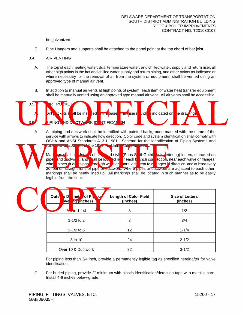
DELAWARE DEPARTMENT OF TRANSPORTATIONSOUTH DISTRICT ADMINISTRATION BUILDING
ROOF & BOILER IMPROVEMENTSCONTRACT NO. T201080107
PIPING, FITTINGS, VALVES, ETC. 15200 - 17GAI#09035H
be galvanized.
E. Pipe Hangers and supports shall be attached to the panel point at the top chord of bar joist.
3.4 AIR VENTING
A. The top of each heating water, dual temperature water, and chilled water, supply and return riser, all other high points in the hot and chilled water supply and return piping, and other points as indicated or where necessary for the removal of air from the system or equipment, shall be vented using an approved type of manual air vent.
B. In addition to manual air vents at high points of system, each item of water heat transfer equipment shall be manually vented using an approved type manual air vent. All air vents shall be accessible.
3.5 DIRT POCKETS
A. Dirt pockets shall be installed at the base of all risers, and as indicated on the drawings.
3.6 PIPING AND DUCTWORK IDENTIFICATION
A. All piping and ductwork shall be identified with painted background marked with the name of the service with arrows to indicate flow direction. Color code and system identification shall comply with OSHA and ANSI Standards A13.1-1981. Scheme for the Identification of Piping Systems and ASHRAE Chapter 34 of the 1989 Fundamentals Handbook.
B. Markings shall use letters of standard style (Sans Serif Gothic bold lettering) letters, stenciled on pipes and ductwork, and shall be located near each branch connection, near each valve or flanges, where pipes or ducts pass through walls or floors, adjacent to changes in direction, and at least every 30 feet on straight runs of pipe or ductwork. Where pipes or ductwork are adjacent to each other, markings shall be neatly lined up. All markings shall be located in such manner as to be easily legible from the floor.
Outside Diameter of Pipe or Covering (Inches)
Length of Color Field (Inches)
Size of Letters (Inches)
3/4 to 1-1/4 8 1/2
1-1/2 to 2 8 3/4
2-1/2 to 6 12 1-1/4
8 to 10 24 2-1/2
Over 10 & Ductwork 32 3-1/2
For piping less than 3/4 inch, provide a permanently legible tag as specified hereinafter for valve identification.
C. For buried piping, provide 2" minimum with plastic identification/detection tape with metallic core. Install 4-6 inches below-grade.
UNOFFICIAL WEBSITE COPY
DELAWARE DEPARTMENT OF TRANSPORTATIONSOUTH DISTRICT ADMINISTRATION BUILDING
ROOF & BOILER IMPROVEMENTSCONTRACT NO. T201080107
PIPING, FITTINGS, VALVES, ETC. 15200 - 18GAI#09035H
3.7 VALVE IDENTIFICATION
A. All valves shall be identified with the appropriate service designation and valve number identification on brass valve tags. Each valve tag shall be 19 gauge brass and 2" diameter with 1/4" black-filled letters over 1/2" black filled numbers. Tags shall be fastened to valves with brass jack chains. Brasstags and fasteners shall be manufactured by Seton Name Plate Company, Champion-America, Inc. or as approved equal.
B. Valve tag numbers shall agree with valve numbers on diagrammatics hereinbefore specified.
C. Provide a minimum of one (1) valve chart with valve numbers indicating valve number, location, purpose, valve type, size, manufacturer and service.
D. Valve charts shall be mounted behind glazed wooden or aluminum frames (style A116) and be hung in the mechanical equipment room. Three (3) additional charts shall be provided for use outside of the boiler room in a plastic protective envelope. Additional copies shall be provided in each copy of the O&M manuals. Valve chart frames and envelopes shall be manufactured by Seton Name Plate Company or as approved equal.
3.8 CLEANING PIPING AND EQUIPMENT
A. The entire steam, condensate, pumped condensate, and heating water piping systems shall be cleaned by filling with a solution of one (1) pound of trisodium phosphate to each 50 gallons of waterand circulating this solution for a period of six (6) hours during which time the system shall reach operating temperature. The systems shall then be flushed with fresh water and refilled with fresh water and purged of all air.
B. All domestic, pumped condensate, and heating water system and waste piping shall be flushed clean with fresh water. See 15400 for domestic potable water cleaning and sterilization.
END OF SECTION 15200
UNOFFICIAL WEBSITE COPY
DELAWARE DEPARTMENT OF TRANSPORTATIONSOUTH DISTRICT ADMINISTRATION BUILDING
ROOF & BOILER IMPROVEMENTSCONTRACT NO. T201080107
MECHANICAL INSULATION 15300 - 1GAI#07035H
SECTION 15300 – MECHANICAL INSULATION
PART 1 - GENERAL
1.1 RELATED DOCUMENTS
A. Drawings, General and Supplementary Provisions of the contract, including but not limited to Section 100 of the DelDOT Standard Specifications for Road and Bridge Construction apply to this section.
1.2 SUMMARY
A. All piping, ductwork and equipment installed under this Contract shall be covered as specified.
1.3 SCOPE
A. The work covered by this specification consists of furnishing all labor, equipment, materials and accessories, and performing all operations required, for the correct fabrication and installation of thermal insulation applied to all piping, equipment, and duct systems, in accordance with applicable project specifications and drawings, subject to the terms and conditions of the contract.
1.4 REFERENCES
A. Thermal insulation materials shall meet the property requirements of one or more of the following specifications as applicable to the specific product or use:
1. American Society for Testing of Materials Specifications:a. ASTM C 547, "Standard Specification for Mineral Fiber Preformed Pipe Insulation"b. ASTM C 533, "Standard Specification for Calcium Silicate Pipe & Block Insulation"c. ASTM C 55, "Standard Specification for Mineral Fiber Blanket and Felt Insulation"d. ASTM C 585, "Recommended Practice for Inner and Outer Diameters of Rigid Pipe
Insulation for Nominal Sizes of Pipe and Tubing (NPS System)"e. ASTM C 612, "Standard Specification for Mineral Fiber Block and Board Thermal
Insulation"f. ASTM C 1136, "Standard Specification for Barrier Material, Vapor, "Type 1 or 2 (Jacket
only)g. ASTM C 795, "Thermal Insulation for Use Over Austenitic Stainless Steel"
B. Insulation materials, including all weather and vapor barrier materials, closures, hangers, supports, fitting covers, and other accessories, shall be furnished and installed in strict accordance with project drawings, plans, and specifications.
1.5 SYSTEM PERFORMANCE
A. Insulation materials furnished and installed hereunder should meet the minimum economic insulation thickness requirements of the North American Insulation Manufacturers’ Association (NAIMA) (formerly known as TIMA), to ensure cost-effective energy conservation performance. Alternatively, materials should meet the minimum thickness requirements of National Voluntary Consensus Standard 90.1 (1989), "Energy Efficient Design of New Buildings," of the American Society of Heating, Refrigeration, and Air-Conditioning Engineers (ASHRAE). However, if other factors such as condensation control or personnel protection are to be considered, the selection of the thickness of insulation should satisfy the controlling factor.
B. Insulation materials furnished and installed hereunder shall meet the fire hazard requirements of any one of the following specifications:
UNOFFICIAL WEBSITE COPY

DELAWARE DEPARTMENT OF TRANSPORTATIONSOUTH DISTRICT ADMINISTRATION BUILDING
ROOF & BOILER IMPROVEMENTSCONTRACT NO. T201080107
MECHANICAL INSULATION 15300 - 2GAI#07035H
1. American Society for Testing of Materials ASTM E 842. Underwriters’ Laboratories, Inc. UL 7233. National Fire Protection Association NFPA 255
A. Calcium silicate products shall include a visual identification system to permit positive field determination of their asbestos free characteristic.
1.6 QUALITY ASSURANCE
A. Insulation materials and accessories furnished and installed hereunder shall, where required, be accompanied by manufacturers’ current submittal or data sheets showing compliance with applicable specifications listed in Section 1.4 above.
B. Insulation materials and accessories shall be installed in a workmanlike manner by skilled and experienced workers who are regularly engaged in commercial insulation work.
C. Provide at project site a sample of each type of insulation hereinafter specified. Display insulation in an "installed" condition, showing typical completed pipe, covers, fittings, ductwork and equipment insulation. No insulation shall be applied until these samples have been accepted by the Engineer. Any insulation work which does not conform to the accepted samples will not be acceptable, and shall be removed and re-installed in a manner acceptable to the Engineer at no additional cost to the Owner.
1.7 DELIVERY AND STORAGE OF MATERIALS
A. All of the insulation materials and accessories covered by this specification shall be delivered to the job site and stored in a safe, dry place with appropriate labels and/or other product identification.
B. The Contractor shall use whatever means are necessary to protect the insulation materials and accessories before, during, and after installation. No insulation material shall be installed that has become damaged in any way. The Contractor shall also use all means necessary to protect work and materials installed by other trades.
C. If any insulation material has become wet because of transit or job site exposure to moisture or water, the contractor shall not install such material, and shall remove it from the job site. An exception may be allowed in cases where the contractor is able to demonstrate that wet insulation when fully dried out (either before installation, or afterward following exposure to system operating temperatures) will provide installed performance that is equivalent in all respects to new, completely dry insulation. In such cases, consult the insulation manufacturer in writing for technical assistance.
PART 2 - PRODUCTS
2.1 GENERAL
A. All materials to be insulated shall be thoroughly cleaned, after completion of successful tests, and shall be covered as specified below. Insulation shall be Owens-Corning Fiberglass, Mannville, Armstrong, or P.P.G, or as approved equal.
2.2 PIPE INSULATION MATERIALS
A. Insulation shall be one piece or half sectional molded fibrous glass with "K" of .24 at 75oF mean temperature, for services for -60oF to +450oF.
UNOFFICIAL WEBSITE COPY

DELAWARE DEPARTMENT OF TRANSPORTATIONSOUTH DISTRICT ADMINISTRATION BUILDING
ROOF & BOILER IMPROVEMENTSCONTRACT NO. T201080107
MECHANICAL INSULATION 15300 - 3GAI#07035H
B. Pipe insulation jacket shall be factory applied vinyl coated, embossed and reinforced vapor barrier laminate, with a perm rating of not more than 0.02 perms. All hot and cold, concealed and exposed butt strips shall be of the same material as jacket. Jacket and butt strips shall be sealed with field applied Benjamin foster adhesive. Jacket and butt strips shall be off-white color and shall beequivalent to Owens-Corning Fiberglass 25-ASJ.
C. For fittings on all piping, valves and flanges, apply fiberglass molded or segmented insulation equal in thickness to the adjoining insulation and securely fasten in place using wire. Apply a skin coat of insulating cement to produce a smooth surface. After cement is dry, apply a light coat of fitting mastic, UL labeled, Type C, for cold water piping, and Type H for hot water piping. Wrap fitting with fiberglass reinforcing cloth overlapping adjoining sections of pipe insulation by 2". Apply a second coat of Type C or Type H mastic over the reinforcing cloth, working it to a smooth finish. As an option to the above fittings, a polyvinyl chloride fitting cover may be supplied.
D. All pipe insulation, jackets, or facings, and adhesives used to adhere jacket or facing to the insulation, including fittings and butt strips, shall have non-combustible fire and smoke hazard system rating and label as tested by ASTM E-84, NFPA 225, and UL 73 not exceeding Flame Spread 25, Fuel Contributed 50, Smoke Developed 50. Accessories such as adhesives, mastic cements, tapes and cloth for fittings shall have the same ratings as listed above. All products or their shipping cartons shall bear the Underwriter's label indicating that flame and smoke ratings do not exceed the above criteria.
E. All concealed pipe insulation shall be held in place with 3/4" wide aluminum bands. Bands shall be spaced to hold the ends and center of each section, and in no case shall the spacing exceed 18". Bands shall not be used in exposed work.
F. For piping having a vapor barrier insulation and for all insulated piping requiring supports, hangers and supports shall be installed outside the insulation. Wherever hangers and supports are installed outside the insulation, pipe insulation protecting shields shall be provided. Where insulation is a load bearing material, of sufficient strength to support the weight of the piping, pipe shields one-third the circumference of the insulation and of a length not less than three times the diameter of the insulation (maximum length 24") shall be provided. Insulation of 7-1/4 pound or greater density will be considered as load bearing for pipe sizes up to and including 2". Where insulation is not of sufficient strength to support the weight of the piping, a half section of calcium silicate insulation, such as Kaylo, shall be provided. Vapor barrier and finish shall be applied as required to match adjoining insulation. In addition, shields shall be furnished as specified above.
G. For piping located outside of the building an aluminum weatherproof jacketing system shall be provided. This system shall be Micro-Lok ML as manufactured by Mannville, Polyweld by Pabco Metals Corp., Childers, or as approved equal, and installed per the manufacturers recommendations. Where outdoor piping is receiving electric heat tape, the insulation shall be oversized so that the heat tape is not compressed tightly to the pipe. Pipe jacketing shall be corrugated (3/16") deep aluminum, .016" thickness of H-14 temper with aluminum strapping of 3/4" width and .020 inch thickness with moisture barrier. Aluminum jacketing elbows shall be smooth, .016" thickness and 1100 alloy. All jacketing shall have an integrally bonded moisture barrier over the entire surface in contact with the insulation. Longitudinal joints shall be applied so they will shed water and shall be sealed completely. Circumferential joints shall be closed using preformed butt strips following manufacturer’s recommendations for securement.
H. In lieu of the above, Armstrong's Self-Seal Armaflex 2000 or equal may be used wherever 2" thickness is allowed for domestic water in service table below. Apply per manufacturer's recommendations.
UNOFFICIAL WEBSITE COPY
DELAWARE DEPARTMENT OF TRANSPORTATIONSOUTH DISTRICT ADMINISTRATION BUILDING
ROOF & BOILER IMPROVEMENTSCONTRACT NO. T201080107
MECHANICAL INSULATION 15300 - 4GAI#07035H
I. All disturbed piping insulation in existing areas shall be re-insulated with insulation type and thickness as specified for new piping. Insulation damaged due to new work and demolition only shall be replaced unless otherwise noted.
J. On cold systems (domestic cold water, chilled water, rainleaders, cooling coil drains, etc.) vapor barrier performance is extremely important. All penetrations of the ASJ and exposed ends of insulation must be sealed with vapor barrier mastic. The ASJ must be protected with either a mastic coating or a suitable vapor retarding outer jacket. Vapor seals at butt joints shall be applied at every fourth pipe section joint and at each fitting to provide isolation of water incursion.
K. Fittings and valves shall be insulated with pre-formed fiberglass fittings, fabricated sections of Fiberglass pipe insulation, Fiberglass pipe and tank insulation, Fiberglass blanket insulation, or insulating cement. Thickness shall be equal to adjacent pipe insulation. Finish shall be with pre-formed PVC fitting covers or as otherwise specified on contract drawings.
L. Flanges, couplings and valve bonnets shall be covered with an oversized pipe insulation section sized to provide the same insulation thickness as on the main pipe section. An oversized insulation section shall be used to form a collar between the two insulation sections with low-density blanket insulation being used to fill gaps. Jacketing shall match that used on straight pipe sections. Rough-cut ends shall be coated with a suitable weather or vapor resistant mastic as dictated by the system location and service. On hot systems where fittings are to be left exposed, insulation ends should be beveled away from bolts for easy access. On cold systems, particular care must be given to vapor sealing the fitting cover or finish to the pipe insulation vapor barrier. All valve stems must be sealed with caulking which allows free movement of the stem but provides a seal against moisture incursion.
M. All piping shall be supported in such a manner that neither the insulation nor the vapor/weather barrier is compromised by the hanger or the effects of the hanger. In all cases, hanger spacing must be such that the circumferential joint may be made outside the hanger. On cold systems, vapor barrier must be continuous, including material covered by the hanger saddle.
1. Piping systems 3" (7.5cm) in diameter or less, insulated with Fiberglass insulation, may be supported by placing saddles of the proper length and spacing, as designated in Owen-Corning Pub. 1-IN-12534, under the insulation.
2. For hot or cold piping systems larger than 3" (7.5 cm) in diameter, operating at temperatures less than +200°F (93°C) and insulated with fiber glass, high density inserts such as wood or foam with sufficient compressive strength shall be used to support the weight of the piping system. At temperatures exceeding +_200°F (93°C), Owens-Corning Pink Calcium Silicate pipe insulation shall be used for high density inserts.
3. Owens-Corning Pink Calcium Silicate pipe insulation may be used to support the entire weight of the piping system provided the hanger saddle is designed so the maximum compressive load does not exceed 100 psi (7kg/cm).
4. Where pipe shoes and roller supports are required, insulation shall be inserted in the pipe shoe to minimize pipe heat loss. Where possible, the pipe shoe shall be sized to be flush with the outer pipe insulation diameter.
5. Thermal expansion and contraction of the piping and insulation system can generally be taken care of by utilizing double layers of insulation and staggering both longitudinal and circumferential joints. Where long runs are encountered, expansion joints may be required where single layers of insulation are being used and should be so noted on the contract drawings.
6. On vertical runs, insulation support rings shall be used.
2.3 PIPING INSULATION THICKNESSES
UNOFFICIAL WEBSITE COPY

DELAWARE DEPARTMENT OF TRANSPORTATIONSOUTH DISTRICT ADMINISTRATION BUILDING
ROOF & BOILER IMPROVEMENTSCONTRACT NO. T201080107
MECHANICAL INSULATION 15300 - 5GAI#07035H
A. Service:
Heating Hot Water Piping 2-1/2" & Larger 1-1/2" thicknessHeating Hot Water Piping 2" & Smaller 1-1/2" thickness
All Drain Piping 1/2" thicknessAll Domestic Hot and Cold Water Piping,including Recirculating Piping 1" thicknessChemical Feed System 1" thickness
2.4 EQUIPMENT
A. The following shall be insulated with Fiberglass Rigid Board Insulation:
1. Air Separators2. Expansion Tanks
B. Insulation for cold surfaces shall be 1-1/2" thickness, 6 lb. density 705 FRK with a "K" of .22 at 75oF mean temperature. Insulation for hot surfaces except as otherwise noted shall be 1-1/2" thickness, 6 lb. density, 705 with a "K" of .22 at 75oF mean temperature. Insulation shall be applied with staggered joints firmly butted and joined. The insulation shall be held in place bysteel bands. Bands shall be 1" by 25 gauge galvanized steel spaced on not over 12" centers. All joints and voids shall be filled with Owens-Corning #110 cement, well troweled into openings. For 705 FRK insulation, all joints and voids shall be FRK taped and vapor sealed. There shall be applied over the insulation surface 1" galvanized wire netting laced together at all edges and wired to the steel bands with 16 gauge soft annealed wire. Over this shall be applied 2" thick layer of Owens-Corning #110 cement applied in two layers. Install metal corner beads at all corners and edges in order to provide a permanent installation. Onto the dry cement surface apply a brush coat of Foster Sealfas 30-36 at the rate of 60-70 square feet per gallon. Embed into wet coating a layer of 8 ounce canvas smoothed out to avoid wrinkles and lap all seams a minimum of 2". Apply a second brush coat of Sealfas 30-36 to the entire surface at the rate of 60-70 square feet per gallon. Cleanouts, nameplates, and manholes shall not be insulated and the insulation on surrounding surfaces shall be neatly beveled off at such openings.
C. If required, boards shall be scored to allow them to conform to curved or irregular surfaces.
D. Mechanical fasteners shall be utilized to hold insulation to surface with bands as required to hold the curvature of the material.
E. Support rings shall be provided to support the top head insulation where required.
F. Outdoor installations require a weather barrier for protection of the insulation jacketing.
2.5 ACCESSORY MATERIALS
A. Accessory materials installed as part of insulation work under this section shall include, but not be limited to:
1. Closure Materials - Butt strips, bands, wires, staples, mastics, adhesives; pressure-sensitive tapes.
2. Field-applied jacketing materials - sheet metal, plastic, canvas, fiber glass cloth, insulating cement; PVC fitting covers.
3. Support Materials - Hanger straps, hanger rods, saddles.4. Fasteners, weld pins/studs, speed clips, insulation washers.
UNOFFICIAL WEBSITE COPY

DELAWARE DEPARTMENT OF TRANSPORTATIONSOUTH DISTRICT ADMINISTRATION BUILDING
ROOF & BOILER IMPROVEMENTSCONTRACT NO. T201080107
MECHANICAL INSULATION 15300 - 6GAI#07035H
5. Metal mesh or expanded metal lagging.
B. All accessory materials shall be installed in accordance with project drawings and specifications, manufacturer’s instructions, and/or in conformance with the current edition of the Midwest Insulation Contractors Association (MICA) "Commercial & Industrial Insulation Standards."
PART 3 - EXECUTION
3.1 WORKMANSHIP
A. The Contractor shall take special care to prevent soiling equipment below or adjacent to areas being insulated. He shall be completely responsible for removing insulation cement splashes and smears and all surfaces that he mars or otherwise soils or defaces, and he will be totally responsible for restoring these damaged surfaces to their like new condition when delivered to the site.
3.2 SITE INSPECTION
A. Before starting work under this section, carefully inspect the site and installed work of other trades and verify that such work is complete to the point where installation of materials and accessories under this section can begin.
B. Verify that all materials and accessories can be installed in accordance with project drawings and specifications and material manufacturers’ recommendations.
C. Verify, by inspecting product labeling, submittal data, and/or certifications which mayaccompany the shipments, that all materials and accessories to be installed on the project comply with applicable specifications and standards and meet specified thermal and physical properties.
3.3 PREPARATION
A. Ensure that all pipe and equipment surfaces over which insulation is to be installed are clean and dry.
B. Ensure that insulation is clean, dry, and in good mechanical condition with all factory-applied vapor or weather barriers intact and undamaged. Wet, dirty, or damaged insulation shall not be acceptable for installation.
C. Ensure that pressure testing of piping or duct systems has been completed prior to installing insulation.
3.4 INSTALLATION
A. Piping Systems
1. General:a. Install all insulation materials and accessories in accordance with manufacturer’s
published instructions and recognized industry practices to ensure that it will serve its intended purpose.
b. Install insulation on piping subsequent to installation of heat tracing, painting, testing, and acceptance tests.
c. Install insulation materials with smooth and even surfaces. Insulate each continuous run of piping with full-length units of insulation, with single cut piece to complete run. Do not use cut pieces or scraps abutting each other. Butt insulation joints firmly to ensure complete, tight fit over all piping surfaces.
d. Maintain the integrity of factory-applied vapor barrier jacketing on all pipe insulation,
UNOFFICIAL WEBSITE COPY

DELAWARE DEPARTMENT OF TRANSPORTATIONSOUTH DISTRICT ADMINISTRATION BUILDING
ROOF & BOILER IMPROVEMENTSCONTRACT NO. T201080107
MECHANICAL INSULATION 15300 - 7GAI#07035H
protecting it against puncture, tear or other damage.
UNOFFICIAL WEBSITE COPY

DELAWARE DEPARTMENT OF TRANSPORTATIONSOUTH DISTRICT ADMINISTRATION BUILDING
ROOF & BOILER IMPROVEMENTSCONTRACT NO. T201080107
MECHANICAL INSULATION 15300 - 8GAI#07035H
2. Fittings:a. Cover valves, fittings, and similar items in each piping system using one of the
following:1) Mitered sections of insulation equivalent in thickness and composition to that
installed on straight pipe runs.2) Insulation cement equal in thickness to the adjoining insulation.3) PVC fitting covers insulated with material equal in thickness and composition to
adjoining insulation.3. Penetrations: Extend piping insulation without interruption through walls, floors, and similar
piping penetrations, except where otherwise specified.4. Joints:
a. Butt pipe insulation against hanger inserts. For hot pipes, apply 3" (7.5cm) wide vapor barrier tape or bank over butt joints. For cold piping apply wet coat of vapor barrier lap cement on butt joints, and seal joints with 3" (7.5cm) wide vapor barrier tape or band.
b. All pipe insulation ends shall be tapered and sealed, regardless of service.
B. Equipment Insulation:
1. General:a. Install insulation in accordance with manufacturer’s published instructions and
recognized industry practices to ensure that it will serve its intended purpose.b. Install insulation on equipment after installation of heat tracing, painting, testing, and
acceptance tests.c. Install insulation materials with smooth, even surfaces. Rework poorly fitted joint. Do
not use joint sealer or mastic as filler for joint gaps and excessive voids resulting from poor workmanship. Apply insulation using staggered joint method for both single and double layer installation, applying each layer of insulation separately.
d. Coat insulated surfaces where specified on contract drawings with layer of insulating cement, troweled in a workmanlike manner, leaving a smooth and continuous surface. Fill in seams, broken edges, and depressions. Cover over wire mesh and joints with cement sufficiently thick to remove surface irregularities.
e. Maintain the integrity of factory-applied vapor barrier jacketing on all insulation, protecting it against puncture, tears or other damage.
f. Where specification calls for field-applied all-service vapor barrier jacketing, it shall be neatly fitted and tightly secured. Lap seams 2" (5cm) (min.). Seal all joints with adhesive. Tape with 3" (7.5cm) matching pressure-sensitive tape or 3" (7.5cm) glass fabric and mastic.
2. Removable Insulation: Provide removable insulation sections to cover parts of equipment which must be opened periodically for maintenance, such as vessel covers, fasteners, flanges, frames and accessories.
3. Areas Left Uninsulated: Items such as boiler manholes, handholes, clean-outs, ASME stamp, and manufacturers’ nameplates, may be left uninsulated unless omitting insulation would cause a condensation problem. When such is the case, appropriate tagging shall be provided to identify the presence of these items. Provide neatly beveled edges at interruptions of insulation.
4. Equipment Exposed to Weather: Protect outdoor insulation from weather by installation of weather barrier mastic protective finish or jacketing as recommended by the jacketing manufacturer.
3.5 FIELD QUALITY ASSURANCE
A. Upon completion of all insulation work covered by this specification, visually inspect the work and verify that it has been correctly installed. This may be done while work is in progress, to assure compliance with requirements herein to cover and protect insulation materials during installation.
UNOFFICIAL WEBSITE COPY

DELAWARE DEPARTMENT OF TRANSPORTATIONSOUTH DISTRICT ADMINISTRATION BUILDING
ROOF & BOILER IMPROVEMENTSCONTRACT NO. T201080107
MECHANICAL INSULATION 15300 - 9GAI#07035H
3.6 PROTECTION
A. Replace damaged insulation that cannot be satisfactorily repaired, including insulation with vapor barrier damage and moisture-saturated insulation.
B. The insulation contractor shall advise the general and/or the mechanical contractor as to requirements for protection of the insulation work during the remainder of the construction period, to avoid damage and deterioration of the finished insulation work.
3.7 SAFETY PRECAUTIONS
A. Insulation Contractor’s employees shall be properly protected during installation of all insulation. Protection shall include proper attire when handling and applying insulation materials, and shall include (but not be limited to) disposable dust respirators, gloves, hard hats, and eye protection.
B. The insulation contractor shall conduct all job site operations in compliance with applicable provisions of the Occupational Safety and Health Act, as well as with all state and/or local safety and health codes and regulations that may apply to the work.
3.8 INSULATION COVERING
A. All pipe and duct insulation shall have an 8 oz. glass cloth or canvas cover neatly cut and pasted over pipe.
END OF SECTION 15300
UNOFFICIAL WEBSITE COPY

DELAWARE DEPARTMENT OF TRANSPORTATIONSOUTH DISTRICT ADMINISTRATION BUILDING
ROOF & BOILER IMPROVEMENTSCONTRACT NO. T201080107
PLUMBING 15400 - 1GAI#09035H
SECTION 15400 - PLUMBING
PART 1 - GENERAL
1.1 RELATED DOCUMENTS
A. Drawings, General and Supplementary Provisions of the contract, including but not limited to Section 100 of the DelDOT Standard Specifications for Road and Bridge Construction apply to this section.
1.2 SUMMARY
A. All exposed bolts, screws, etc., shall be vandal-proof.
B. All plumbing materials, equipment and fixtures shall be new and of best grade, free of defects and complete with all required appurtenances and accessories.
C. Piping and insulation are specified under other sections.
D. Use "Sani-Sett" setting compound for fixtures.
E. Provide all materials, equipment and perform all labor required to install plumbing system complete as specified, as drawings indicated and as required by the State of Delaware, Comar Latest Edition, and the National Standard Plumbing Code, International Plumbing Code, Kent County, and all other authorities having jurisdiction.
F. Provide loose key handle and lock shield cap stops for all plumbing fixtures and equipment. Stops are to be accessible.
G. Provide P Traps on fixtures for which traps have not been included as part of furnished equipment.Trap size to equal size of fixture tailpiece.
H. All exposed metal parts of fixtures shall be chromium-plated brass. Piping, fittings, valves, traps and accessories including escutcheons for piping shall be chromium-plated where exposed in finished areas.
I. Provide deep seal traps and trap priming where floor drains are connected to sanitary systems.
PART 2 - PRODUCTS
2.1 GAS-FIRED INSTANTANEOUS TANKLESS WATER HEATER
A. Gas water heater shall be Rheem, Noritz, Bradford White, or as approved equal.
B. Unit shall have a 5-year limited heat exchanger warranty and a 5-year limited parts warranty.
C. Unit shall be designed to burn natural or propane gas and certified by CSA International to the latest edition of ANSI Standard Z21.10.3CSA 4.3.
D. Units shall be vented with 3-inch/5-inch concentric stainless steel pipe at a distance not exceeding 29 feet (or equivalent) with 3 elbows terminating vertically or horizontally.
E. Water heater is rated for 15- psi working water pressure and 300 psi test pressure.
UNOFFICIAL WEBSITE COPY
DELAWARE DEPARTMENT OF TRANSPORTATIONSOUTH DISTRICT ADMINISTRATION BUILDING
ROOF & BOILER IMPROVEMENTSCONTRACT NO. T201080107
PLUMBING 15400 - 2GAI#09035H
F. Unit shall have a coated steel case, copper heat exchanger, stainless steel dual/fuel burner, aluminum gas control valves, 3/4” gas inlet connection, and 3/4” brass inlet/outlet water connections.
G. The heater shall be controlled by an internal circuit board that monitors inlet and outlet temperatures with installed thermistors, sensing and controlling flow rate to set point temperature with air-fuel ratio controls in order to maintain thermal combustion efficiency.
H. Provide safety features such as flame sensor system, thermal cut-off fuses, lightning protection device, overheat prevention device, freeze protection device, and fan rotator detector.
I. Multi-system applications that require two (2) units shall be installed by connecting the units using a single cable-only connection.
J. The units shall meet or exceed the energy requirements of ASHRAE 90.1b-1992 and listed by SCAQMD Rule 1146.2 Low Nox.
PART 3 - EXECUTION
3.1 TESTING
A. After plumbing fixtures are connected, all piping and fixtures shall be tested for operation and a smoke or peppermint test shall be made on all soil, waste and vent piping.
B. After the building has been occupied and the various equipment is in actual use, the Contractor shall make an operating test of all equipment at a time directed by the Engineer to determine that all contract requirements are met.
3.5 CLEANING AND STERILIZATION
A. After final testing for leaks, all potable water lines shall be thoroughly flushed, by plumbing contractor, to remove foreign material. Before placing the systems in service, sterilize the new water lines in accordance with authorities having jurisdiction and the following procedure:
1. Through a 3/4" hose connection in each branch main prior to connecting to existing piping, pump in sufficient sodium hypochlorite to produce a free available chlorine residual of not less than 200 ppm.
2. Proceed upstream from the point of chlorine application opening all faucets and taps until chlorine is detected. Close faucets and taps when chlorine is evident.
3. When chlorinated water has been brought to every faucet and tap with a minimum concentration of 200 ppm chlorine, retain this water in the system for three hours. Caution: Over-concentration of chlorine and more than three (3) hours of retention may result in damage to the piping system.
4. At the end of the retention period, no less than 100 ppm of chlorine shall be present at the extreme end of the system.
5. Proceed to open all faucets and taps and thoroughly flush all new lines until the chlorine residual in the water is less than 1.0 ppm.
6. Obtain representative water sample from the system for analysis by an independent and recognized bacteriological laboratory.
7. If the sample tested for coliform organisms is negative, a letter and laboratory report shall be submitted by the service organization to the contractor, certifying successful completion of the sterilization. Additionally, this report shall be forwarded to the Owner as well as be included in the O&M Manual.
UNOFFICIAL WEBSITE COPY

DELAWARE DEPARTMENT OF TRANSPORTATIONSOUTH DISTRICT ADMINISTRATION BUILDING
ROOF & BOILER IMPROVEMENTSCONTRACT NO. T201080107
PLUMBING 15400 - 3GAI#09035H
8. If any samples tested indicate the presence of coliform organisms, the entire sterilization procedure shall be repeated.
END OF SECTION 15400
UNOFFICIAL WEBSITE COPY
DELAWARE DEPARTMENT OF TRANSPORTATIONSOUTH DISTRICT ADMINISTRATION BUILDING
ROOF & BOILER IMPROVEMENTSCONTRACT NO. T201080107
PERFORMANCE TESTING AND BALANCING 15500 - 1GAI#09035H
SECTION 15500 – PERFORMANCE TESTING AND BALANCING
PART 1 - GENERAL
1.1 RELATED DOCUMENTS
A. Drawings, General and Supplementary Provisions of the contract, including but not limited to Section 100 of the DelDOT Standard Specifications for Road and Bridge Construction apply to this section.
1.2 SUMMARY
A. The Mechanical Contractor shall select and employ an impartial, independent balancing agency to provide testing and balancing services for the Heating, Ventilating and Air Conditioning (HVAC) Systems of this project.
B. The work included in this section consists of furnishing labor, instruments, and tools required in testing, adjusting and balancing the HVAC systems, as described in these specifications or shown on accompanying drawings. Services shall include checking equipment performance, taking the specified measurements, and recording and reporting the results.
C. The items requiring testing, adjusting, and balancing include the following:
Air Systems:Motor-Operated DampersUnit Heaters
Hydronic Systems:Heating Water SystemDomestic Hot WaterTerminal Heating UnitsPumps
1.2 QUALIFICATIONS OF THE BALANCING AGENCY
A. The balancing agency shall be a member of the Associated Air Balance Council (AABC) and have an Engineer certified by the National Examining Board.
B. The certified Test and Balance Engineer shall be responsible for supervision and certification for the total work herein specified.
C. All final reports shall be signed and officially stamped by the certified Test and Balance Engineer.
1.3 STANDARDS
A. The balancing agency shall perform the services specified herein in accordance with the Associated Air Balance Council's National Standards, including revisions, to the date of the contract.
B. All terms in this specification shall have their meaning defined as stated in the National Standards.
1.4 COORDINATION
A. It will be necessary for the balancing agency to perform its services in close coordination with the Mechanical Contractor.
UNOFFICIAL WEBSITE COPY
DELAWARE DEPARTMENT OF TRANSPORTATIONSOUTH DISTRICT ADMINISTRATION BUILDING
ROOF & BOILER IMPROVEMENTSCONTRACT NO. T201080107
PERFORMANCE TESTING AND BALANCING 15500 - 2GAI#09035H
B. The plans and specifications have indicated meters, valves, dampers, and other devices for the purpose of adjusting the system to obtain optimum operating conditions. It will be the responsibilityof the mechanical contractor to install these devices in a manner that will leave them accessible and readily adjustable. The balancing agency shall provide guidance if there is a questionable arrangement of a control or balancing device.
C. The Mechanical Contractor, Temperature Control Contractor and suppliers of the HVAC equipment shall all coordinate with the balancing agency to provide all necessary data on the design and proper application of the system components.
1.5 RESPONSIBILITIES OF THE MECHANICAL CONTRACTOR
A. The Mechanical Contractor shall sufficiently complete the installation and start all HVAC systems to insure they are working properly and shall perform all other items as described hereinafter to assist the balancing agency in performing the testing and balancing of the HVAC system.
B. Air Distribution Systems:
1. Verify installation for conformity to design.2. Ensure that all splitters, extractors, and volume - and fire dampers are properly located and
functional. Dampers serving requirements of minimum and maximum outside - return - relief, and exhaust air shall provide tight closure and full opening, with a smooth and free operation.
3. Verify that all new return supply - return - exhaust and transfer grilles; registers, and diffusers are installed and operational.
4. Ensure that air-handling systems, units, and associated apparatus, such as heating and cooling coils, filter sections, access doors, etc., are blanked and/or sealed to eliminate excessive bypass or leakage of air.
5. Ensure that all fans (supply, return, relief, ) are operating and free of vibration. All fans and drives shall be checked for proper fan rotation and belt tension. Overload protection shall be of proper size and rating. A record of motor current and voltage shall be made to verify that the motors do not exceed nameplate rating.
6. Make any necessary changes to the sheaves, belts, and dampers, as required by the balancing agency, at no additional cost to the owner.
7. Install clean filters.
C. In each classroom space, provide sound measuring and testing. Noise levels shall not exceed 50 Db.
1.6 RESPONSIBILITIES OF THE TEMPERATURE CONTROL CONTRACTOR
A. The temperature control contractor shall complete the installation of the temperature control system, and operate and test all control systems to ensure they are functioning properly as designed. The temperature control contractor shall assist the balancing agency in testing and balancing the HVAC systems, as described hereinafter.
1. Verify that all control components are installed in accordance with project requirements and are functional, including all electrical interlocks, damper sequences, air and water reset, and fire and freeze stats.
2. Verify that all controlling instruments are calibrated and set for design operating conditions.3. Calibrate room thermostats after installation, and before the thermostat control verification
tests are performed. The balancing agency shall prove the accuracy of final settings by taking temperature readings. The readings shall be in a typical conditional space for each separately controlled zone.
UNOFFICIAL WEBSITE COPY
DELAWARE DEPARTMENT OF TRANSPORTATIONSOUTH DISTRICT ADMINISTRATION BUILDING
ROOF & BOILER IMPROVEMENTSCONTRACT NO. T201080107
PERFORMANCE TESTING AND BALANCING 15500 - 3GAI#09035H
4. The Temperature Control Contractor shall allow sufficient time in the project to provide assistance and instruction to the balancing agency in the proper use and setting of control components such as, but not limited to, computers, static pressure controllers, or any other device that may need set points changed so that the testing and balancing work can be performed.
1.7 DEFICIENCIES
A. Any deficiencies in the installation or performance of a system or component observed by the TAB agency shall be brought to the attention of the appropriate responsible person.
B. The work necessary to correct items on the deficiency listing shall be performed and verified by the affected contractor before the TAB agency returns to retest. Unresolved deficiencies shall be noted in the final report.
PART 2 - PROCEDURES
2.1 GENERAL
A. Perform all testing and balancing in complete accordance with AABC National Standards for Field Measurements and Instrumentation.
B. Furnish all test instruments and equipment. All instruments must have been calibrated within six (6) months prior to use and shall be checked for accuracy prior to and during the work.
C. Review all systems designs and equipment manufacturers data and be completely familiar with the work before proceeding.
D. Report all malfunctions or deficiencies to the contractor so that corrective action can be taken. Repeat tests where required until design conditions are achieved.
E. Where systems or equipment cannot be balanced or adjusted to design conditions, determine the cause and submit a complete report to the Engineer.
F. Retest or rebalance the system as requires during the guarantee period.
G. Test and balance all systems under adequate load condition. If, in the opinion of the Engineer, there is insufficient load to properly test and balance the systems, perform sufficient preliminary balancing and adjustment to permit operation of the systems until such time as final testing and balancing can be done.
2.2 AIR SYSTEM PROCEDURES
A. The balancing agency shall perform the following testing and balancing functions in accordance with the Associated Air Balance Council's National Standards:
1. Fan Speeds - Test and adjust fan RPM to achieve design CFM requirements.
2. Current and Voltage - Measure and record motor current and voltage.3. Pitot-tube Traverse - Perform a Pitot-tube traverse of main supply and return ducts to obtain
total CFM. If a Pitot-tube traverse is not practical, the summation of the outlets or inlets may be used. An explanation why a traverse was not made must appear on the appropriate data sheet.
UNOFFICIAL WEBSITE COPY
DELAWARE DEPARTMENT OF TRANSPORTATIONSOUTH DISTRICT ADMINISTRATION BUILDING
ROOF & BOILER IMPROVEMENTSCONTRACT NO. T201080107
PERFORMANCE TESTING AND BALANCING 15500 - 4GAI#09035H
4. Outside Air - Test and adjust system minimum outside air by Pitot-tube traverse. If a Pitot-tube traverse is not practical, the percentage of outside air may be determined bycalculations from the return air, outside air, and mixed air temperatures. Make allowances for heat of compression and motor heat where applicable.
5. Static Pressure - Test and record system static pressures, including suction and discharge static pressure of each fan. Record hood static pressure at kitchen hood exhaust tap.
6. Air Temperature - Take wet-bulb and dry-bulb air temperatures on the entering and leaving side of each cooling coil. Dry-bulb temperature shall be taken on the entering and leaving side of each heating coil.
7. Zone Ducts - Adjust zone ducts to within design CFM requirements. At least one zone balancing damper shall be completely open.
8. Main Ducts - Adjust main ducts to within design CFM requirements and traverse for total CFM quantities.
9. Branch Ducts - Adjust branch ducts to within design CFM requirements. Multi-diffuser branch ducts shall have at least one outlet or inlet volume damper completely open.
l0. Tolerances - Test and balance new diffusers, grilles, and registers to within l0 percent of design requirements.
11. Identification - Identify the location and area of each new grille, diffuser, register, and terminal box. This information shall be recorded on air outlet data sheets.
l2. Description - Record the size, type, and manufacturer of each new diffuser, grille, and register on air outlet data sheets.
l3. Minimizing Drafts - Adjust all diffusers, grilles, and registers to minimize drafts in all areas.
2.3 LIFE SAFETY CONTROLS
A. The TAB agency shall test and record life safety control operation on the HVAC equipment. It shall verify the installation of required smoke detectors in air handling equipment (AHE), and shall verifyoperation of the smoke detector by activating the smoke detector and observing air handler shutdown. With the controls and alarm contractors, the TAB agency shall verify the operation of interconnected systems such as the AHE smoke detector’s activation of the fire alarm system and the alarm system’s activation of the life safety control sequences.
2.4 VERIFICATION OF TEMPERATURE CONTROL
A. The balancing agency shall be assisted by the temperature control contractor in verifying the operation and calibration of all temperature control systems. The following tests shall be conducted:
1. Verify that all control components are installed in accordance with project requirements and are functional, including all electrical interlocks, damper sequences, air and water reset.
2. Verify that all controlling instruments are calibrated and set for design operating conditions.3. Verify the accuracy of the final settings by taking temperature readings. The readings shall be
in a typical conditioned space for each separately controlled zone.
PART 3 - EXECUTION
3.1 TEST AND BALANCE REPORTS
A. The test and balance report shall be complete with logs, data, and records as required herein. All logs, data, and records shall be typed on white bond paper and bound. The report shall be certified accurate and complete by the balancing agency's certified test-and balance engineer.
UNOFFICIAL WEBSITE COPY

DELAWARE DEPARTMENT OF TRANSPORTATIONSOUTH DISTRICT ADMINISTRATION BUILDING
ROOF & BOILER IMPROVEMENTSCONTRACT NO. T201080107
PERFORMANCE TESTING AND BALANCING 15500 - 5GAI#09035H
B. Three (3) copies of the test and balance report are required and shall be submitted to the Engineer. If in the opinion of the Engineer, test results or portions thereof are incomplete or inconclusive, repeat necessary portions of the work to the satisfaction of the Engineer.
C. The report shall contain the following general data in a format selected by the balancing agency:
1. Project Number2. Contract Number3. Project Title4. Project Location5. Project Architect6. Project Mechanical Engineer7. Test & Balance Agency8. Test & Balance Engineer9. General Contractor
l0. Mechanical Subcontractor 11. Dates tests were performed
l2. Certification
D. The test and balance report shall be recorded on report forms conforming to the recommended forms in the AABC National Standards.
3.2 TEST REPORT FORMS
A. Rooftop unit, multizone unit, heating and ventilating unit, single zone unit, and fan test forms. Record the following on each air-handling equipment test form:
1. Manufacturer, model number, and serial number.2. All design and manufacturer-rated data.3. Total actual CFM by traverse if practical. If not practical, the sum of the outlets may be used,
or a combination of each of these procedures. For specific systems, such as ones with diversity, see the AABC National Standards.
4. Suction and discharge static pressure of each fan, as applicable.5. Outside-air and return-air total CFM.6. Actual operating current, voltage and brake horsepower of each fan motor.7. Final RPM of each fan.8. Fan and motor sheave manufacturer, model, size, number of grooves, and center distance.9. Belt size and quantity.
B. Heating and Cooling-Coil Test Forms - Record the following items on each test form:
1. Manufacturer2. All design and manufacturer's rated data.3. Rated and actual water pressure drop through each coil and related GPM.4. Rated and actual static pressure drop across each coil.5. Entering and leaving water temperatures.6. Wet-bulb and dry-bulb temperatures entering and leaving each cooling coil; dry-bulb
temperatures entering and leaving each heating coil.
END OF SECTION 15500
UNOFFICIAL WEBSITE COPY

DELAWARE DEPARTMENT OF TRANSPORTATIONSOUTH DISTRICT ADMINISTRATION BUILDING
ROOF & BOILER IMPROVEMENTSCONTRACT NO. T201080107
HEATING, VENTILATING AND AIR CONDITIONING 15600 - 1GAI#09035H
SECTION 15600 - HEATING, VENTILATING, AND AIR CONDITIONING
PART 1 - GENERAL
1.1 RELATED DOCUMENTS
A. Drawings, General and Supplementary Provisions of the contract, including but not limited to Section 100 of the DelDOT Standard Specifications for Road and Bridge Construction apply to this section.
1.2 SUMMARY
A. The work to be performed shall include all labor, materials and equipment necessary to furnish and install complete, all mechanical equipment as shown on drawings, hereinafter specified orreasonably implied, and leaving the same in satisfactory operation condition. It is the intent that systems be installed complete with all items necessary to accomplish this purpose.
PART 2 - PRODUCTS
2.1 PUMPS
A. Base-mounted Pumps - End Suction:
1. Furnish and install base mounted centrifugal end suction pumps to circulate heating hot water, and chilled water to the various items of equipment throughout the building, associated with the HVAC system. Pumps shall have sizes and capacities as indicated on the drawings.
2. All pumps shall be suitable for the service and temperatures designated and shall conform to the following requirements.
3. Pumps shall be cast iron bronze fitted and shall be suitable for up to 125 psi working pressure and up to 250oF water temperature. Pumps shall have center-line discharge for positive venting, flanged, bodies, and same size suction and discharge. Pumps shall incorporate a grease lubrication system and be so designed that the bearing assembly can be removed in one piece. A water slinger shall be provided between the mechanical seal and bearing areas. Pump shafts shall be steel with an AISI 416 stainless steel sleeve, and be coupled to the motor shaft by a noiseless non-metallic coupler with guard. Impellers shall be one piece cast bronze, dynamically balanced. Motors shall be 1750 rpm.
4. Pumps shall be designed so that they shall not overload at low heads and shall not develop excessive pressure under throttled flow conditions or overload anywhere on the operating curve. Operating performance curves shall be submitted for approval. Provide gauge tappings on each pump flange. Furnish dust caps at all oil fill tubes.
5. Units shall be provided with motors of not less than the horsepower indicated, suitable for the service and available electrical characteristics. Units shall be controlled as hereinafter specified. After installation and prior to operation, each pump shall be aligned. Motors shall be as specified hereinbefore.
6. Pumps shall be FE Series as manufactured by Taco, Armstrong, Bell and Gossett, or Weinman.
B. In-Line Circulating Pump:
1. Furnish and install in-line circulating pumps shown on the drawings. Pump and motor shall be equipped with sleeve bearings for quiet operation. Pumps shall be suitable for up to 175 psi working pressure and up to 300 degrees F water temperature as per ASA B16.1. Pump rating curves shall be the result of testing and rating in accordance with the procedures of the Hydraulic Institute.
UNOFFICIAL WEBSITE COPY

DELAWARE DEPARTMENT OF TRANSPORTATIONSOUTH DISTRICT ADMINISTRATION BUILDING
ROOF & BOILER IMPROVEMENTSCONTRACT NO. T201080107
HEATING, VENTILATING AND AIR CONDITIONING 15600 - 2GAI#09035H
2. Pumps shall be non-overloading throughout the range of the curves. Pumps shall have center-line discharge for positive venting, flanged bodies, and same size suction and discharge. Pumps shall incorporate a disc type lubrication system and be so designed that the bearing assembly can be removed in one piece. One bearing assembly shall be suitable for all sizes of the inline pumps furnished. Sump oil temperature may not exceed 180°F when circulating 250°F water with a 90°F. ambient. Vent and drain openings at least 3 square inches in area and a water slinger shall be provided between the mechanical seal and bearing area. This water slinger shall be integral with shaft sleeve.
3. Pump body shall be cast iron and pump shafts shall be alloy steel with cupro-nickel sleeve covering all wetted parts, and be coupled to the motor shaft by a noiseless non-metallic coupler. Impellers shall be one-piece cast bronze, dynamically balanced. Pumps shall have a two-piece mechanical seal assembly easily replaceable without the use of special tools. Motors shall be resilient mounted, 1750 RPM, and require no external overload protection when used with single phase current.
4. Domestic water pumps shall be all bronze construction.5. Pumps shall be Taco 110 Series or as approved equal of Armstrong or Bell and Gossett.
2.2 EXPANSION TANKS
A. Furnish and install as shown on the drawings, pre-pressurized captive air bladder type expansion tank pre-charged with air. Tank shall be suitable for a maximum working pressure of 125 psi and constructed and certified to ASME Section VII. It shall have a replaceable elastomeric bladder suitable for a maximum operating temperature of 240oF (115oC). It shall have an integral steel base ring for vertical mounting. Expansion tank shall be CA Series as manufactured by Taco, Bell & Gossett, Amtrol, or Wheatley. Domestic water expansion tanks shall be suitable for domestic water applications.
2.3 AIR SEPARATORS
A. Furnish and install as shown on the plans an external air control unit consisting of a steel tank. The unit shall have flanged inlet and outlet connections and strainer removal connection. The removable strainer shall be of stainless steel with 3/16" diameter perforations and a free area of not less than five times the cross-sectional area of the connecting pipe. Unit shall have separate top fittings for connection to system make-up water and for air vent. There shall be a bottom connection for blowdown cleaning. Unit shall be constructed in accordance with ASME boiler and pressure vessel code and stamped 125 psig design pressure. Provide ring bases for pad-mounted air separators. The air control unit shall be Model K as manufactured by Taco, Bell & Gossett, Amtrol, or Wheatley.
2.4 HOT WATER UNIT HEATERS
A. Furnish and install horizontal delivery, hot water unit heaters as shown on the drawings.
B. Casings - Horizontal Models - Casings shall be formed from 18- or 20-gauge die-formed steel, and consist of front and back halves. Ribs are formed in top, bottom, and both sides for added strength. Both halves are joined together at top and bottom, utilizing the condenser mounting screws for attachment. All corners are rounded with no breaks. Casing top is provided with threaded hanger connections for unit suspension. Fan venturi is formed in casing back half.
C. Fans - Fans are aluminum on ALL units and are secured to a steel hub. Each fan is balanced and designed specifically for unit heater application.
D. Coils - Coils are of the extended-surface type, utilizing aluminum fins and DLP-type copper tubes with steel supply and return connections. Tubes are mechanically bonded to collars of the fins. The condensers are warranted for operation at steam or hot water pressures up to 150 lbs. per sq. in.
UNOFFICIAL WEBSITE COPY

DELAWARE DEPARTMENT OF TRANSPORTATIONSOUTH DISTRICT ADMINISTRATION BUILDING
ROOF & BOILER IMPROVEMENTSCONTRACT NO. T201080107
HEATING, VENTILATING AND AIR CONDITIONING 15600 - 3GAI#09035H
gauge, and/or temperatures up to 375°F. Fins are continuous across the width and depth of the condenser.
E. Motor - All motor wiring is terminated in an electrical junction box either supplied with the unit heater or as an integral part of the motor. Motors shall be totally enclosed 120/60/1 Class "B" insulated, PSC Type. 1/25 through 1/8 HP are sleeve bearing. 1/6 through 3/4 HP are ball bearing. All single phase motors have built in overload protection. Sleeve bearing motors can be oiled. Ball bearing motors are permanently lubricated. Provide toggle type disconnect switch with the unit.
F. Finish - All metal surfaces of the casing are treated to prevent the formation and spread of rust. Standard models are finished in gray-green baked enamel.
G. Safety Fan Guard - Horizontal units shall be equipped with a combination fan guard/motor-operated bracket. The guard is constructed of steel rod. Vertical units are supplied with an outlet fan guard covering the opening in the bottom of the unit.
H. Air Deflectors - Unit heaters shall be furnished with horizontal air deflectors as standard equipment. The deflectors may be adjusted to most any position desired for downward, upward, or straight-out air flow.
I. Unit heaters shall be as manufactured by Vulcan, AirTherm, Dunham Bush, Modine, Sterling, McQuay, or as approved equal.
2.5 WATER TREATMENT SERVICES
A. Complete chemical water treatment service shall be provided by an organization regularly engaged in water treatment, RCCO Corp., Aquatel Ind., Inc., Mogul Corp., Oilin, Inc., Industrial Chemical Systems, HVAC Services, Inc., or as approved equal. The service shall provide all equipment, chemicals and labor necessary to prevent corrosion, inhibit scale build-up and minimize organic growth for a period of 2 years starting from building acceptance. Service visits for the purpose of adding chemicals to feeding equipment, regulating bleed-off, inspecting and adjusting water treatment equipment, and obtaining samples of laboratory analysis will be performed at monthly intervals for closed systems and every two weeks for open systems during the entire guarantee period. Chemicals shall not be injurious to water side equipment and construction materials. Records of all injurious to water side equipment and construction materials. Records of all service visits, chemical additions, laboratory tests, etc., shall be maintained and shall be made available to owner after each visit during guarantee period.
B. Systems to be protected shall include the chilled water system, heating water system, and dual temperature system. Services shall include flushing and cleaning of piping systems specified under "Pipe, Valves and Fittings" and "Plumbing" section, furnishing and installing all chemical treatment equipment and accessories to perform the water treatment specified below.
C. Contractor shall perform an analysis of the building water supply as a basis of the chemical treatment. Contractor shall provide the Owner with written instructions for chemical feeding bleed-off, blowdown control and testing procedures, provide all required chemicals during the guarantee period, and provide all required test kits.
D. Contractor shall maintain the following conditions in each system:
Heating Waterph 7.0 to 10.0Organic Inhibitor ---
UNOFFICIAL WEBSITE COPY

DELAWARE DEPARTMENT OF TRANSPORTATIONSOUTH DISTRICT ADMINISTRATION BUILDING
ROOF & BOILER IMPROVEMENTSCONTRACT NO. T201080107
HEATING, VENTILATING AND AIR CONDITIONING 15600 - 4GAI#09035H
Cycles* ---Organic ---Buffered Nitrate 1000 ppm to 180oF
2000 ppm to 180oFChromate (LowMolybdate 100 to 150 ppm
*Actual cycles of concentration to be determined from analysis of make-up water.
E. Chemical Feeding Equipment: Provide chemical feeding equipment, as specified below, to introduce chemicals into each system only when the system is operating. Closed Recirculating Systems - Dual Temperature and Heating Water System: Five (5) gallon steel by-pass feeder installed across circulating pump suction and discharge lines, with tank and piping insulated using the same thickness and type of insulation as provided for the piping system. Provide filter.
F. Before adding cleaning chemical to the closed system, all air handling unit coils, unit ventilator coils and miscellaneous heating and cooling equipment shall be isolated by closing the inlet and outlet valves and opening the bypass valves. This is done to prevent dirt and solids from lodging in the coils.
G. Closed Recirculating Systems shall be filled and sufficient detergent and dispersant added to remove all dirt, oil, and grease. System shall be circulated for no more than six (6) hours after which a drain valve at the lowest point shall be opened and allowed to bleed while the system continues to circulate. The automatic make-up valve shall be checked to be sure it is operating. Bleeding shall continue until water runs clear and all detergent is removed. A sample of water shall be tested and if PH exceeds the PH of the make-up water, flushing shall be resumed.
H. After chemical cleaning is satisfactorily completed, open the inlet and outlet valves to each coil and close the bypass valves. Also, clean all strainers.
I. Boilers shall be boiled out with an alkaline-type boiling-out compound to remove grease, oil, mill scale, and other foreign matter. The compound shall be used at the rate of 12 pounds per 20 boiler horsepower. After boiling out period, the boilers should be completely drained, flushed, refilled with fresh water and vented. All water treatment chemicals shall comply with Delaware Water Resources Laws and Regulations.
2.6 BOILER/BURNER UNITS
A. Furnish and install as herein specified new boiler/burner units for low pressure water heating service and arranged for completely automatic operation firing gas/oil. Boiler shipped knocked-down for field assembly by installing contractor.
B. Each boiler shall be furnished complete with an insulated metal jacket; forced draft burner, cast iron smoke hood with integral 14 gauge aluminized steel damper; pressure-tight front and rear flame observation ports with covers; steel angle floor rails; cast iron burner mounting plate with insulation and additional controls and devices as hereafter specified.
C. Safety controls and limit devices shall be installed in accordance with the requirements of NFPA 31 and NFPA 54. In every case, the boiler installation shall be accomplished in accordance with the recommended good practice and installation requirements of the ASME Boiler and Pressure Vessel Code, Section 4.
D. The boiler/burner units shall have been rated in accordance with the Hydronics Institute Testing and Rating Standard for Heating Boilers, and shall be performance tested and listed by I=B=R at +0.10 inches (w.c.) draft.
UNOFFICIAL WEBSITE COPY
DELAWARE DEPARTMENT OF TRANSPORTATIONSOUTH DISTRICT ADMINISTRATION BUILDING
ROOF & BOILER IMPROVEMENTSCONTRACT NO. T201080107
HEATING, VENTILATING AND AIR CONDITIONING 15600 - 5GAI#09035H
E. The boiler/burner units shall be Model GO28HE-W-13 as manufactured by Smith Cast Iron Boilers.
F. Boiler sections shall be manufactured from a flake graphite eutectic cell cast iron. The sections shall be of the wet base type designed for pressure firing and it shall be constructed and tested for 80 P.S.I water working pressure. In accordance with the A.S.M.E. Section IV Rules for the Construction of Heating Boilers. Individual sections will have been subjected to a hydrostatic pressure test of 200 PSIG at the factory before shipment and they shall be marked, stamped or cast with the A.S.M.E. Code symbol. Boilers with less than 200-PSIG pressure test will not be acceptable for this project. Boiler sections shall be cast in the U.S.A. to meet U.S. Steel content requirements.
G. Boiler sections shall be of one piece design incorporating the furnace space and flue gas collector space with perimeter joints between the sections arranged for permanent pressure sealing with high temperature ceramic fiber rope. Precision CNC machined, upper and lower ports for connecting the water space of adjacent sections shall be sealed by means of a graphite composition port connector. The port connectors will be inert and have a temperature rating of 1800° F. The port connector will meet ASTM F-37 and ASTM F-36 standards for sealability and recovery. Sections shall be assembled with short draw rods, tightened to final torque after the section assembly is complete. The boiler shall have an oval upper supply port to provide reduced water velocity and aid in air separation and removal.
H. The boiler shall be supplied with an Integral Return Temperature Stabilizer or “RTS”. The “RTS” shall be installed in a 5” opening located in the upper portion of the rear section. The internal port area of the “RTS” shall have a minimum cross section area of 58.4 square inches to provide for mixing and blending of the return water before it comes in contact with the internal surfaces of the boiler to enhance thermal shock resistance. Boilers that rely on external pumps(s) and or external valves arrangements SHALL NOT be considered equal or acceptable
I. All boiler discharges shall be piped to floor drains as shown on the contract drawings and as indicated by the consulting engineer. Blowdown valves shall be brass, ball type and not less than one-inch IPS and they shall discharge to a floor drain or away from the boiler as directed by the Consulting Engineer. Pipe ends shall be cut at a 45-degree angle to prevent a cap or plug from being installed. Hangars or standoffs to prevent the valve body from undue stress or strain shall support all such discharge piping.
J. Boiler drain valves shall be connected to the lowest water space available and shall be installed with pipe and fittings to connect the bottom blow off full size to drain.
K. All individual sections shall have legs to provide support on both sides. Two- 3" x3" base angles shall be furnished to be set under field assembled boilers to provide level support for the sections when shimmed and grouted to a concrete floor. The base angles shall be tapped to receive the supporting frame for the insulated metal jacket.
L. Insulating metal jacket shall consist of 20-gauge steel panels fitted with 3” 1 1/2 Lb./Cu. Ft. density fiberglass insulation glued to the inside of the panels. Jacket panels shall be finished with blue hammertone paint baked on and shall be arranged with slots and knockouts to accommodate the boiler piping and to allow jacket installation after the piping is in place. Left and Right side panels shall be furnished with two recessed handles located above and below the horizontal centerline of the jacket for easy removal and to provide access to the boiler clean out covers and draw rods.
M. Clean-out covers shall be sized and located to allow full access to the extended pin type heating surface areas for cleaning and inspection of the Heat Transfer Rods. Clean-out covers shall have grooves to contain high temperature ceramic fiber rope seals for gas-tight fit to the sections and
UNOFFICIAL WEBSITE COPY
DELAWARE DEPARTMENT OF TRANSPORTATIONSOUTH DISTRICT ADMINISTRATION BUILDING
ROOF & BOILER IMPROVEMENTSCONTRACT NO. T201080107
HEATING, VENTILATING AND AIR CONDITIONING 15600 - 6GAI#09035H
incorporate cast iron horizontal baffles to reduce short circuiting of flue gases and also enhance performance by maximizing heat transfer.
N. Stop valves of the outside stem and yoke type shall be provided in the supply and return pipe connections to the boiler. Provisions shall be made for the expansion and contraction of the heating mains connected to the boiler by providing substantial anchorage at suitable points and assisted by the use of swing joints to allow the piping to expand and contract without imposing excessive forces on the boiler castings.
O. Boiler shipped Knocked-Down for field assembly by installing contractor.
P. Boiler installation shall be accomplished within acceptable A.S.M.E. piping practices and requirements and in strict accordance with the boiler manufacturer's recommendations and instructions.
Q. A hydrostatic pressure test of one-and-one-half times the working pressure of the boiler shall be conducted. Such tests shall be of such duration as necessary and as directed by the engineer to ensure the boiler has been assembled and installed correctly with no leaks or improper operating conditions.
R. The installing contractor shall contact and notify the Boiler Inspections Divisions of the State when the installation of the boiler, burner and controls is substantially complete. Installing contractor shall request an Inspection of the boiler to be conducted by the State Boiler Inspector and to have a Certificate of Inspection issued upon satisfactory inspection.
S. Each boiler shall be supplied with a minimum of the following trim:
1. A.S.M.E. Schedule Side Outlet Relief Valve set for 40 PSIG.2. Pressure Temperature Gauge3. Honeywell L4006E Manual Reset High limit 4. Honeywell L4007A Operating Temperature Control5. T991A Modulating Control (Select for Modulation)6. L4007A Low-High-Low Control (Select for Low-High-Low)
T. Each unit shall include a forced draft flame retention type burner having a ring of recessed gas ports with an orifice for each port, primary air adjustment and externally mounted gas pilot and a high pressure atomizing oil burner tested by Underwriters Laboratories and complying with the rules and regulations UL, as well as the local authorities having jurisdiction.
U. The gas train shall be UL listed and shall consist of the following items:1. Main Motorized Gas Valves2. High and Low Gas Pressure Switches3. Auxiliary Solenoid Gas Valve4. Lubricated Shutoff Cock5. Maxitrol Gas Pressure Regulator
V. The burner shall be driven by a 2.0HP 3450 RPM, 208 / 240 / 460 volts, 60 hertz, (single) (three) phase alternating current motor. Control circuit voltage shall be supplied from a 115-volt control circuit transformer.
W. The burner shall be arranged for Modulation firing of both fuels. The burner shall provide for an open damper prepurge through a damper motor.
UNOFFICIAL WEBSITE COPY
DELAWARE DEPARTMENT OF TRANSPORTATIONSOUTH DISTRICT ADMINISTRATION BUILDING
ROOF & BOILER IMPROVEMENTSCONTRACT NO. T201080107
HEATING, VENTILATING AND AIR CONDITIONING 15600 - 7GAI#09035H
X. The burner shall include the appropriate oil piping and pumping to supply the nozzle arrangement, dual automatic safety shutoff valves, return oil pressure control, air flow switch and combustion air damper control.
Y. Oil pressure shall be obtained from a 300-PSIG fuel unit driven by the burner motor. The fuel unit shall have two-stage pumping gears, self-contained pressure regulating valve and shall be suitable for 3450 RPM service with suction vacuum up to 15" Hg.
Z. Burner shall be equipped with an electronic flame safeguard system and scanner. The control shall be a Honeywell UV Flame System microprocessor-based, burner management control system with self-diagnostics and non-volatile memory.
AA. Control Panel - The burner mounted control panel shall include the following: Indicator lights: Power-On, Main Fuel, Ignition, Main Flame Failure (Alarm), Pilot Flame Failure (Alarm), High Gas Pressure (Alarm), Low Gas Pressure (Alarm), Low Water (Alarm). Alarm Bell to sound on Main Flame Failure, Pilot Flame Failure, High Gas Pressure, Low Gas Pressure, and Low Water. Alarm Reset System shall be provided to silence the Bell but the light will remain lit until the fault has been corrected. A low fire hold switch shall be included to allow the burner to be adjusted to intermediate firing positions as job conditions require.
BB. The contractor shall provide factory certified lightoff for the burners and one year of warranty service on burner controls starting on the lightoff date. The warranty service shall include labor materials to replace any parts or controls, which fail in service as the result of a defect in material or manufacture.
CC. The owner shall be responsible for the cost of normal maintenance, such as replacement of filter medium, cleaning, oiling, service control system malfunction, etc., shall be paid for by the owners.
DD. The owner's operating personnel shall be instructed in the operation and maintenance of the burner and controls at the time of lightoff. The owner shall arrange to have the people who require training to be present at the lightoff.
2.7 POWER ROOF VENTILATOR
A. Furnish and install as shown on the Drawings, V-belt drive centrifugal roof exhausters. Ventilator housings shall be of heavy gauge spun aluminum construction and shall be weatherproof, incorporating an integral weather shield with external fasteners of PTFE coating or stainless steel. Pulleys shall be cast iron with variable pitch on motor, oil-resistant, non-static, non-sparking belts to provide 24,000 hours of normal service and L-10 life bearings. Roof ventilators shall be mounted on acoustical curbs and all ventilators shall include fan safety switch mounted in junction box factory-wired to factory-installed junction box.
B. Fan wheels shall be centrifugal design and shall have been statically and dynamically balanced. Power roof ventilators and prefabricated curbs shall be the product of the same manufacturer. Sound attenuating curbs shall be Sone-Master, as manufactured by ACME Engineering, Pate Company, Cook, Greenheck, or as approved equal.
C. Fans shall have integral factory-formed base. Housings shall be provided with wiring channel and are to be of the direct discharge design. Motor and fan assembly shall be on vibration-isolating mounts. Capacities and standard or special characteristics shall be as scheduled on the Drawings.
D. Each fan shall be equipped with a motor-operated damper and 1/2-inch galvanized birdscreen.
E. See Drawings for capacities.
UNOFFICIAL WEBSITE COPY
DELAWARE DEPARTMENT OF TRANSPORTATIONSOUTH DISTRICT ADMINISTRATION BUILDING
ROOF & BOILER IMPROVEMENTSCONTRACT NO. T201080107
HEATING, VENTILATING AND AIR CONDITIONING 15600 - 8GAI#09035H
F. Fans shall be by Greenheck, Cook, or as approved equal.
2.8 CARBON MONOXIDE DETECTOR SYSTEM
A. Carbon monoxide detector shall be a System Sensor Model Number CO1224T, listed to Underwriters Laboratories UL 2075 for gas and vapor detectors and sensors or equal. The detector shall be equipped with a sounder and a trouble relay. The detector’s base shall be able to mount to a single-gang electrical box or direct (surface) mount to the wall or ceiling. Wiring connections shall be made by means of SEMS screws. The detector shall provide dual color LED indication, which blinks to indicate normal standby, alarm, or end-of-life. When the sensor supervision is in a trouble condition, the detector shall send a trouble signal to the panel. When the detector gives a trouble or end-of-life signal, the detector shall be replaced. The detector shall provide a means to test CO gas entry into the CO sensing cell. The detector shall provide this with a test mode that accepts CO gas from a testagent and alarms immediately upon sensing CO entry.
B. The CO1224T operating voltage shall be 12/24 VDC. The audible signal for the detector shall be 85 dB in alarm. Standby current shall be 20 mA. Alarm current shall be 40 mA (75 mA test). Alarm contact ratings shall be0.5 A @ 30 VDC. Trouble contact ratings shall be 0.5A @ 30 VDC.
C. The CO1224T shall measure: Length: 5.1 inches; Width: 3.3 inches; Height: 1.3 inches. The CO1224T weight shall be approximately 7 ounces. The operating temperature range shall be 32 deg F to 104 deg F (0 deg C to 40 deg C). The detector’s operating humidity range shall be 22 to 90% RH. The CO1224T input terminals shall be 14 to 22 AWG.
D. In Normal (Standby) Mode, the green LED shall blink 1 time per minute. In Alarm Mode, the red LED shall blink in temporal 4 pattern and the sounder will sound in temporal 4 pattern.
1. Real Test Feature: The System Sensor CO1224T carbon monoxide detector with Real Tests can evaluate the functionality of the CO sensing cell using canned test agent. NOTE: Check with local Codes and the AHJ to determine whether or not a functional gas test is desired for an installation.
2. Hush Feature: Pushing the Test/Hush button will silence the sounder for 5 minutes (except in Real Test mode).
3. Trouble Feature: When the detector is in a trouble condition, it will send a trouble signal to the panel.
4. End-of-Life Timer: After the detector’s internal sensor has reached the end of its life, a trouble signal will be sent to the panel. This will indicate that it is time to replace the detector. An electrochemical carbon monoxide detector lifespan is approximately six years, and the detector must be replaced by the date marked on the inside of the product.
PART 3 – EXECUTION – NOT USED
END OF SECTION 15600
UNOFFICIAL WEBSITE COPY
DELAWARE DEPARTMENT OF TRANSPORTATIONSOUTH DISTRICT ADMINISTRATION BUILDING
ROOF & BOILER IMPROVEMENTSCONTRACT NO. T201080107
AIR DISTRIBUTION 15700 - 1GAI#09035H
SECTION 15700 – AIR DISTRIBUTION
PART 1 - GENERAL
1.1 RELATED DOCUMENTS
A. Drawings, General and Supplementary Provisions of the contract, including but not limited to Section 100 of the DelDOT Standard Specifications for Road and Bridge Construction apply to this section.
1.2 SUMMARY
A. The fabrication and installation of all ductwork, together with related equipment, shall comply with the standards of the National Fire Protection Association, as set forth in NFPA Standard No. 90A, as well as with the requirements of the Sheet Metal and Air Conditioning Contractors' National Association, Inc., and the latest edition of the ASHRAE Guide.
B. All duct sizes shown are net inside clear dimensions. Where internal duct lining is used, increase duct sizes accordingly to provide the indicated net free area. Unless otherwise indicated size runouts, drops, and connections to grilles, registers, diffusers, fans, coils, louvers, filters, and other equipment to the full size of the equipment connection.
C. Minor changes may be made in duct sizes where required to fit the available space, provided the indicated net free area and approximate aspect ratio are maintained.
D. Smoothly transition all ductwork and prevent excessive or unnecessary turbulence or pressure loss.
PART 2 - PRODUCTS
2.1 BREACHING AND STACKS - BOILER AND DOMESTIC WATER HEATER
A. The factory-built modular connector, manifold and breaching system shall be laboratory-tested and listed by Underwriters Laboratories, for use with building heating equipment which produces exhausted flue gases at a temperature not exceeding 1000 degrees Fahrenheit (F) under continuous operating conditions and not exceeding 1400 degrees F under intermittent operating conditions (See UL 103 Sections 17 and 18, respectively) when burning gaseous, solid or liquid fuels as described in NFPA 211. The breaching system shall be designed and installed to be gas tight and thus prevent leakage of combustion products into a building. The system shall be designed to compensate for all fuel gas induced thermal expansions.
B. The double wall breaching shall have an inner gas carrying pipe of Type 304 stainless steel for natural gas. There shall be a nominal 1-inch insulation between the walls. The outer jacket shall be aluminum-coated steel. The materials and construction of the modular sections and accessories shall be as specified by the terms of the product’s UL listing.
C. The stack system shall be installed according to the Manufacturer’s installation instructions and shall comply with the Codes and Standards of the State of Delaware, latest edition of BOCA.
D. Inner pipe joints shall be sealed by use of factory-supplied V bands and sealant as specified in the Manufacturer’s installation instructions.
E. When installed according to the Manufacturer’s installation instructions, the piping and its supporting system shall resist side loads (whether system is horizontal or vertical) at least 1.5 times the weight per foot of the piping. Wall supports shall support 40 feet of pipe with a factor of safety of at least
UNOFFICIAL WEBSITE COPY

DELAWARE DEPARTMENT OF TRANSPORTATIONSOUTH DISTRICT ADMINISTRATION BUILDING
ROOF & BOILER IMPROVEMENTSCONTRACT NO. T201080107
AIR DISTRIBUTION 15700 - 2GAI#09035H
four (4). Plate supports shall support (as verified by Manufacturer testing) 200 feet of pipe in 6-inch through 20-inch ID sizes and 100 feet of pipe in 24-inch ID and larger sizes with a factor of safety of at least four (4).
F. The entire breaching system from the boiler and hot water generator to termination; including all required accessories, (ventilated roof thimbles, wall thimbles, wall support brackets, guy pipes, storm collar, guy connectors, expansion joints, discharge cone, supports, etc.), shall be from one manufacturer. Provide 45 degree lateral tee for entry to vertical stacks and horizontal manifolds. Provide drain tee cap at bottom of vertical run and at end of manifold. Provide drain section above horizontal connection to vertical stack. Terminate with rain cap and provide the necessary straight lengths, increaser/reducer, elbows, hood transitions, expansion joints, flanges, thimbles, supports, guides, guy tensioner, guy sectioning, guy pipes (minimum of two, 1-1/2” galvanized), or wires (3/8” minimum braided steel--three minimum), joints, sealants, etc., as required for a complete system designed for the connected equipment and installed per Code and Manufacturer’s recommendations.
G. The breaching shall be warranted against functional failure due to defects in material and Manufacturer’s workmanship for a period of ten years from the date of delivery. Drawings showing the actual layout and drawn to scale shall be provided by the Manufacturer. The system shall be installed as designed by the Manufacturer and in accordance with the terms of the Manufacturer’s 10-year warranty and in conjunction with sound engineering practice. The inner diameter for breaching and stack shall be verified by the Manufacturer’s computations. The computation shall be technically sound, shall follow ASHRAE calculation methods, and incorporate the specific flow characteristics of the inner pipe. The Contractor shall furnish the exact boiler model and operating characteristics of the inner pipe. Operating characteristics shall include flue gas flow rate, BTU input, outlet temperature, local altitude, stack layout, and available external pressure at boiler outlet, etc., necessary to determine system operation at maximum and minimum levels of burner turndown range.
H. Boiler and hot water generator breaching and stack and appliance breaching and stack shall be Type IPS as manufactured by Selkirk Metalbestos, Type DW Plus by Van Packer, Metal Fab, or approved equal of Ampco.
PART 3 - EXECUTION
3.1 BREECH/DUCTWORK INSTALLATION
A. Coordinate ductwork with other work and install ducts at proper elevations and locations to maintain indicated ceiling heights and clearances. Provide all elbows, transitions, offsets, connections, and other fittings necessary to fit the work into place or to connect to equipment or diffusers. Method of duct support connection to structure and slabs shall be approved byStructural Engineer, submit shop drawings.
B. Substantially support ductwork with structural shapes, flat bars, or formed strap hangers securely attached to the building structure by means of bolts, clamps, or inserts. Support vertical ducts by angles attached to the duct and resting on the floor or supported by brackets or hangers attached to the building structure. Strap hangers shall be 16 gauge minimum galvanized steel formed under the bottom edge of duct. Use square 1/4" thick washer tight against the bend on upper strap attachments to horizontal surfaces. Place all supports external to the ductwork and out of the air stream. Provide additional supports at coils and other concentrated loads. Arrange supports so that duct weight is not transmitted to ceilings, fans or other equipment.
UNOFFICIAL WEBSITE COPY

DELAWARE DEPARTMENT OF TRANSPORTATIONSOUTH DISTRICT ADMINISTRATION BUILDING
ROOF & BOILER IMPROVEMENTSCONTRACT NO. T201080107
AIR DISTRIBUTION 15700 - 3GAI#09035H
C. Prevent direct contact between ductwork and building surfaces or other equipment. Where ducts pass through walls, partitions, floors, ceilings, or roofs, pack and seal the space around the duct with an approved fire-safe inert material.
D. Use galvanized or corrosion-resistant hangers, supports, brackets, and hardware.
E. Furnish and install NFPA approved duct connections where shown and at all connections to fans. Use glass-reinforced neoprene fabric, roll-formed to sheet metal strips or flanges. Support adjacent ductwork to provide sufficient slack in the connection.
F. See NFPA 90A-13-3-3-8, and latest publication of SMACNA. Prevent direct contact between ductwork and building surfaces or other equipment. The opening in the construction around the duct shall not exceed one inch average clearance on all sides. Where ducts pass through walls partitions, floors, ceilings, or roofs, pack and seal the space around the duct with an approved fire-safe inert material capable of preventing the passage of flame and hot gases sufficiently to ignite cotton waste when subjected to the same NFPA 251 time-temperature conditions required for fire barrier penetration.
G. Weld stainless steel duct by tungsten inert gas method using Type 308 wire to fill voids and depressions. Spot weld angles to ducts. Grind and polish welds leaving no visible signs of joining.
END OF SECTION 15700
UNOFFICIAL WEBSITE COPY
DELAWARE DEPARTMENT OF TRANSPORTATIONSOUTH DISTRICT ADMINISTRATION BUILDING
ROOF & BOILER IMPROVEMENTSCONTRACT NO. T201080107
VIBRATION CONTROL 15975 - 1GAI#09035H
SECTION 15975 – VIBRATION CONTROL
PART 1 – GENERAL
1.1 RELATED DOCUMENTS
A. Drawings, General and Supplementary Provisions of the contract, including but not limited to Section 100 of the DelDOT Standard Specifications for Road and Bridge Construction apply to this section.
1.2 SUMMARY
A. Provide all labor and materials necessary to furnish and install vibration control systems on this project as herein specified and/or shown on the drawings.
B. Mount all mechanical equipment on suitable vibration isolators so as to prevent transmission of vibration into or through the building structure. Isolators shall be as manufactured by Mason Industries, Inc., Korfund, Inc., or approved equal, and shall be selected by the isolator manufacturer for each item of equipment in accordance with requirements hereinafter specified.
C. The equipment manufacturer shall supply all pump and motor bases, fan and motor bases, cradles, pipe/duct hangers, spring and/or neoprene isolators, neoprene pads, flexible connectors, etc. as a coordinated package by a single manufacturer.
D. Select isolators for uniform static deflections according to distribution of weight; and for not less than the indicated isolation efficiency with the lowest rotational speed of equipment as the disturbing frequency.
E. Isolators and bases shall be stable during stopping and starting of equipment without transverse or eccentric movement of equipment, and shall be designed to resist horizontal forces of equipment which may operate unbalanced.
F. In general, select isolators on the basis of criteria as specified in the latest ASHRAE Applications Handbook.
PART 2 - PRODUCTS
2.1 MANUFACTURER
A. Isolators shall be the equivalent of the following types by Mason Industries, Inc.
2.2 CORROSION PROTECTION FOR STEEL PARTS
A. Where steel parts are exposed to weather provide hot-dipped galvanized coating of at least 2 ounces of zinc per square foot of surface. Coat springs with neoprene.
2.3 NEOPRENE
A. Grade durometer 40, 50 OR 60 AND OIL RESISTANT.
UNOFFICIAL WEBSITE COPY
DELAWARE DEPARTMENT OF TRANSPORTATIONSOUTH DISTRICT ADMINISTRATION BUILDING
ROOF & BOILER IMPROVEMENTSCONTRACT NO. T201080107
VIBRATION CONTROL 15975 - 2GAI#09035H
2.4 SPRING ISOLATORS
A. General: Provide spring isolators or protected spring isolators that are adjustable and laterallystable with free-standing springs of horizontal stiffness at minimum 80 percent of the vertical (axial) stiffness.For machine-attached and floor-attached restraining elements, separate from metal-to-metal contact by neoprene cushions 1/8 inch thick minimum. Provide neoprene acoustic friction pads at least 1/4 inch thick.
B. Spring Isolator: Spring type isolators shall be free standing and laterally stable without any housing and complete with 1/4" neoprene acoustical friction pads between the baseplate and the support. All mountings shall have leveling bolts that must be rigidly bolted to the equipment. Spring diameters shall be no less than 0.8 of the compressed height of the spring at rated load. Springs shall have a minimum additional travel to solid equal to 50% of the rated deflections, compressed spring height and solid spring height. Mountings shall be type SLF as manufactured by Mason Industries, Inc., or as approved equal.
2.5 SUSPENSION ISOLATORS
A. General: Provide hangers with suspension isolators encased in open steel brackets. Isolate hanger rods from isolator steel brackets with neoprene-lined opening.
B. Suspension Neoprene Isolators: Provide double-deflection elements with minimum 3/8 inch deflection.
C. Suspension Spring Isolators: Vibration hangers shall contain a steel spring and 0.3" deflection neoprene element in series. The neoprene element shall be molded with a rod isolation bushing that passes through the hanger box. Spring diameters and hanger box lower hole sizes shall be large enough to permit the hanger rod to swing thru a 30o arc before contacting the hole and short circuiting the spring. Springs shall have a minimum additional travel to solid equal to 50% of the rateddeflection. Submittals shall include a scale drawing of the hanger showing the 30o capability. Hangers shall be type 30N.
D. Precompressed Suspension Spring Isolators: Vibration hangers shall be as described in "C" above, but they shall be Precompressed to the rated deflection so as to keep the piping or equipment at a fixed elevation during installation. The hangers shall be designed with a release mechanism to free the spring after the installation is complete and the hanger is subjected to its full load. Deflection shall be clearly indicated by means of a scale. Submittals shall include a scale drawing of the hangershowing the 30o capability. Hangers shall be type PC30N.
E. Ductwork Suspension Spring Isolators: Vibration hangers shall contain a steel spring located in a neoprene cup manufactured with a grommet to prevent short circuiting of the hanger rod. The cup shall contain a steel washer designed to properly distribute the load on the neoprene and prevent its extrusion. Spring diameters and hanger box lower hole sizes shall be large enough to permit the hanger rod to swing thru a 30o arc before contacting the hole and short circuiting the spring. Spring shall have a minimum additional travel to solid equal to 50% of the rated deflection. Hangers shall be provided with an eye bolt on the spring end and provision to attach the housing to the flat iron duct straps. Submittals shall include a scale drawing of the hanger showing the 30o capability. Hangers shall be type W30.
2.6 THRUST RESTRAINTS
A. Adjustable spring thrust restraints, able to resist the thrust force with at least 25 percent unused capacity. The operating spring deflection shall be not less than 50 percent of the static deflection of
UNOFFICIAL WEBSITE COPY
DELAWARE DEPARTMENT OF TRANSPORTATIONSOUTH DISTRICT ADMINISTRATION BUILDING
ROOF & BOILER IMPROVEMENTSCONTRACT NO. T201080107
VIBRATION CONTROL 15975 - 3GAI#09035H
the isolation supporting the machinery. The spring element shall be contained within a steel frame and designed so it can be preset for thrust at the factory and adjusted in the field to allow for a maximum of 1/4" movement at start and stop. The assembly shall be furnished with one rod and angle bracket for attachment to both the equipment and ductwork or the equipment and the structure.Horizontal restraints shall be attached at the centerline of thrust and symmetrically on either side of the unit. Horizontal thrust restraints shall be Type WB.
2.7 BASES
A. Structural Bases: Vibration isolator manufacturer shall furnish integral structural steel bases. Bases shall be rectangular in shape for all equipment other than centrifugal refrigeration machines and pump bases which may be "T" or "L" shaped. Pump bases for split case pumps shall include supports for suction and discharge base ells. All perimeter members shall be beams with a minimumdepth equal to 1/10th of the longest dimension of the base. Beam depth need not exceed 14" provided that the deflection and misalignment is kept within acceptable limits as determined by the manufacturer. Height saving brackets shall be employed in all mounting locations to provide a base clearance of one inch. Bases shall be Type WF.
B. Structural Rails: Vibration isolator manufacturer shall provide steel members welded to height saving brackets to cradle machines having legs or bases that do not require a complete supplementary base. Members shall be sufficiently rigid to prevent strains in the equipment. Inverted saddles shall be Type ICS.
C. Concrete Bases: Vibration isolator manufacturer shall furnish rectangular structural beam or channel concrete forms for floating foundations. Bases for split case pumps shall be large enough to provide support for suction and discharge base ells. The base depth need not exceed 12" unless specifically recommended by the base manufacturer for mass or rigidity. In general, bases shall be a minimum of 1/12th of the longest dimension of the base, but not less than 6". Forms shall include minimum concrete reinforcement consisting of half inch bars or angles welded in place on 6" centers running both ways in a layer 1-1/2" above the bottom, or additional steel as is required by the structural conditions. Forms shall be furnished with steel members to hold anchor-bolt sleeves when the anchor bolts fall in concrete locations. Height saving brackets shall be employed in all mounting locations to maintain a 1" clearance below the base. Bases shall be Type K.
2.8 FLEXIBLE CONNECTORS FOR PIPING
A. General: Straight flexible connectors rated for temperatures, pressures, and fluids to be conveyed. Provide flexible connectors with the strength 4 times operating pressure at highest system operating temperature. Provide elbow flexible connectors with a permanently set angle.
B. Metal Flexible Connectors: Fabricated of Grade E phosphor bronze, monel or corrugated stainless steel tube covered with comparable bronze or stainless steel braid restraining and pressure cover. Sizes 3" and larger shall be flanged. Sizes 2-1/2" and smaller shall have male nipples. Lengths shall be as indicated:
Nominal Diameter (Inches) Length (Inches)
1/2" 12"3/4" 12"1-1/2" 12"1-1/2" 12"2" 12"2-1/2" 12"
UNOFFICIAL WEBSITE COPY
DELAWARE DEPARTMENT OF TRANSPORTATIONSOUTH DISTRICT ADMINISTRATION BUILDING
ROOF & BOILER IMPROVEMENTSCONTRACT NO. T201080107
VIBRATION CONTROL 15975 - 4GAI#09035H
Nominal Diameter (Inches) Length (Inches)
3" 18" 4" 18" 5" 24" 6" 24" 8" 24"
10" 24"12" 36"14" 36"16" 36"
Hoses shall be installed on the equipment side of the shut-off valves horizontally and parallel to the equipment shafts wherever possible. Hoses shall be Type BSS.
PART 3 - EXECUTION
3.1 GENERAL PROVISIONS
A. Install vibration-and-noise isolation materials and equipment as indicated and in accordance with machinery manufacturer's instructions.
B. Where neoprene elements of vibration isolator may be subjected to high pipe temperatures above 160oF, provide metal heat shields or thermal isolators.
C. All vibration isolators exposed to weather shall be hot dipped galvanized with springs coated with neoprene in accordance with paragraph 2.2 hereinbefore described.
D. Machinery: Provide vibration isolators, flexible connectors and seismic snubbers in accordance with manufacturer's recommendations. Machinery with spring isolators or protected spring isolators shall rock or move freely within limits of stops or seismic snubber restraints.
E. Stability: Isolators shall be stable during starting and stopping of machinery without traverse and eccentric movement of machinery that would damage or adversely affect the machinery or attachments.
F. Lateral Motion: The installed vibration isolation systems for each piece of floor or ceiling mounted machinery shall have a maximum lateral motion under machinery start up and shut down conditions of not more than 1/4-inch. Restrain motions in excess by approved spring mountings.
G. Unbalanced Machinery: Provide foundation suspension systems specifically designed to resist horizontal forces for machinery with large unbalanced horizontal forces. Vibration isolator systems shall conform to the machinery manufacturer's recommendations.
H. Nonrotating Machinery: Mount Non-rotating machinery in systems which includes rotating or vibrating machinery on isolators having the same deflection as the hangers and supports to which the pipe is connected.
I. Unitized Machinery Assemblies: Unitized assemblies such as chillers with evaporator and condenser, and top-mounted centrifugal compressor or unitized absorption refrigeration machines, structurally designed with end supports, may be mounted on steel rails and springs in lieu of steel bases and springs. Where the slab or deck is less than 4 inches thick, provide spring isolation units with the deflection double that of the vibration isolation schedule, up to a maximum static deflection of 5 inches.
UNOFFICIAL WEBSITE COPY

DELAWARE DEPARTMENT OF TRANSPORTATIONSOUTH DISTRICT ADMINISTRATION BUILDING
ROOF & BOILER IMPROVEMENTSCONTRACT NO. T201080107
VIBRATION CONTROL 15975 - 5GAI#09035H
J. Roof and Upper Floor Mounted Machinery: On the roof or upper floors, mount machinery on isolators with vertical stops. Rest isolators on beams or structures designed and installed in accordance with the SMACNA ASMM Plate 61.
K. Electrical Connections: Provide flexible conduit or multiple conductor cable connections for machinery with sufficient extra length to permit 2-inch minimum displacement in any direction without damage.
3.2 FLEXIBLE PIPE CONNECTORS
A. Provide flexible connectors in accordance with manufacturers instructions where piping systems serving vibration isolated equipment and as shown on the drawings. Flexible connectors shall be installed near the connection to the equipment. Where liquid pulsation dampening is required, flexible connectors with spherical configuration may be used. Provide restraints for pipe connectors at pumps to prevent connector failure upon pump start-up.
3.3 ISOLATION FOR SPECIFIC EQUIPMENT
A. The vibration isolator manufacture shall provide isolators for all pieces of equipment provided for the job. Isolator shall be selected by the isolator manufacturer on the basis of criteria as specified in the latest ASHRAE Applications Handbook, unless a more stringent requirement is indicated on the drawings.
END OF SECTION 15975
UNOFFICIAL WEBSITE COPY

DELAWARE DEPARTMENT OF TRANSPORTATIONSOUTH DISTRICT ADMINISTRATION BUILDING
ROOF & BOILER IMPROVEMENTSCONTRACT NO. T201080107
GENERAL ELECTRICAL REQUIREMENTS 16010 - 1GAI#09035H
SECTION 16010 - GENERAL ELECTRICAL REQUIREMENTS
PART 1 - GENERAL
1.1 RELATED DOCUMENTS
A. Drawings, General and Supplementary Provisions of the contract, including but not limited to Section 100 of the DelDOT Standard Specifications for Road and Bridge Construction apply to this section.
1.2 GENERAL
A. Provide all labor, materials, equipment and services necessary for and incidental to the complete installation and operation of all electrical work.
B. Unless otherwise specified, all shop drawings and submissions shall be made to, and acceptances and approvals made by, the ENGINEER.
C. Conform to the requirements of all rules, regulations, and codes of local, state, and federal authorities having jurisdiction. Conform to the National Electrical Code and all NECA – National Electrical Installation Standards (NEIS).
D. Perform the work in a first-class, substantial, and workmanlike manner. Any materials installed which do not present an orderly and neat workmanlike appearance shall be removed and replaced when so directed by the Engineer, at the Contractor's expense.
E. Coordinate the work of all trades.
F. Carefully examine all contract drawings and fit the work in each location without substantial alteration.
G. Be responsible for all construction means, methods, techniques, procedures, and phasing sequences used in the work. Furnish all tools, equipment and materials necessary to properly perform the work in a first class, substantial, and workmanlike manner, in accordance with the full intent and meaning of the Contract Documents.
H. The Contractor shall provide other work and services not otherwise included in the Contract Documents that are customarily forwarded in accordance with generally-accepted construction practices.
1.3 PERMITS, INSPECTIONS, AND FEES
A. The Contractor shall obtain and pay for all charges and fees, and deliver all permits, licenses, certificates of inspection, etc., required by the authorities having jurisdiction. Deliver inspection, approval, and other certificates to the Owner prior to final acceptance of the work.
B. File necessary plans, prepare documents, give proper notices, and obtain necessary approvals.
C. Permits and fees shall comply with the General Requirements of the Contract Documents.
D. Contractor shall notify Inspection Authorities to schedule inspections of work and arrange for all inspections. All work shall be subject to field inspections.
E. Notify Engineer in advance of scheduled inspections.
UNOFFICIAL WEBSITE COPY

DELAWARE DEPARTMENT OF TRANSPORTATIONSOUTH DISTRICT ADMINISTRATION BUILDING
ROOF & BOILER IMPROVEMENTSCONTRACT NO. T201080107
GENERAL ELECTRICAL REQUIREMENTS 16010 - 2GAI#09035H
F. An electrical foreman, superintendent or other supervisor shall be in attendance for all scheduled inspections.
G. The Contractor shall provide an electrical certificate from an independent electrical inspection agency approved by the Owner and the State of Delaware Fire Marshal. The Contractor shall submit certificate prior to final payment invoice. The Contractor shall payall fees, including filing fees.
1.4 ELECTRICAL WORK UNDER OTHER DISCIPLINES
A. Mechanical Equipment and Systems
1. In general, power wiring and motor starting equipment for mechanical equipment and systems are furnished and installed by Electrical.
2. Certain mechanical units contain starters, contacts, transformers, fuses, wiring, etc., required for fans, pumps, etc., furnished with the equipment from the factory. When this equipment is supplied from the factory, the Electrical Contractor must supplypower circuit(s) to the unit and a disconnecting means as shown. Coordinate with Mechanical Contractor so that one, and only one, set of starters, fuses, switches, etc., is provided and installed.
3. In general, control and interlock equipment for HVAC systems (including associated wiring, conduit, transformers, relays, contacts, etc.) is furnished by Mechanical. Electrical Contractor shall install and connect all such equipment as necessary.
4. Controls, wiring, conduit, transformers, etc., for smoke, fire, and motor-operated dampers are provided by Mechanical. Electrical shall install and connect all such equipment.
B. Carefully review the contract documents and coordinate the electrical work under the various Disciplines.
1.5 CONTRACTOR QUALIFICATION
A. Any Contractor performing work shall be fully qualified and acceptable to the Engineer. Submit the following evidence for approval:
1. A list of not less than five (5) comparable projects that the Contractor completed.2. Letters of reference from not less than three (3) registered professional engineers,
general contractors, or building owners, explaining Contractor proficiency, quality of work, or other attribute on projects of similar size or substance.
3. Local or State license.4. Membership in trade or professional organization where required.5. Copy of Master Electrician’s License.
B. Contractor is any individual, partnership, corporation, or firm performing work by Contract or subcontract on this project.
C. Acceptance of a subcontractor will not relieve the Contractor of any contractual requirements or his responsibility to supervise and coordinate the various trades.
D. Supervisory Qualifications: The electrical work on the project shall be under the direct supervision of a licensed Master Electrician.
E. Qualifications of Installers:
UNOFFICIAL WEBSITE COPY
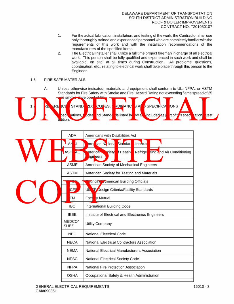
DELAWARE DEPARTMENT OF TRANSPORTATIONSOUTH DISTRICT ADMINISTRATION BUILDING
ROOF & BOILER IMPROVEMENTSCONTRACT NO. T201080107
GENERAL ELECTRICAL REQUIREMENTS 16010 - 3GAI#09035H
1. For the actual fabrication, installation, and testing of the work, the Contractor shall use only thoroughly trained and experienced personnel who are completely familiar with the requirements of this work and with the installation recommendations of the manufacturers of the specified items.
2. The Electrical Installer shall utilize a full time project foreman in charge of all electrical work. This person shall be fully qualified and experienced in such work and shall be available, on site, at all times during Construction. All problems, questions, coordination, etc., relating to electrical work shall take place through this person to the Engineer.
1.6 FIRE SAFE MATERIALS
A. Unless otherwise indicated, materials and equipment shall conform to UL, NFPA, or ASTM Standards for Fire Safety with Smoke and Fire Hazard Rating not exceeding flame spread of 25 and smoke developed of 50.
1.7 REFERENCED STANDARDS, CODES, ORDINANCES AND SPECIFICATIONS
A. Specifications, Codes and Standards listed below are included as part of this specification, latest edition.
ADA Americans with Disabilities Act
ANSI American National Standards Institute
ASHRAE American Society of Heating, Refrigerating and Air ConditioningEngineers
ASME American Society of Mechanical Engineers
ASTM American Society for Testing and Materials
CABO Council of American Building Officials
DCFS UMCP Design Criteria/Facility Standards
FM Factory Mutual
IBC International Building Code
IEEE Institute of Electrical and Electronics Engineers
MEDCO/SUEZ Utility Company
NEC National Electrical Code
NECA National Electrical Contractors Association
NEMA National Electrical Manufacturers Association
NESC National Electrical Society Code
NFPA National Fire Protection Association
OSHA Occupational Safety & Health Administration
UNOFFICIAL WEBSITE COPY

DELAWARE DEPARTMENT OF TRANSPORTATIONSOUTH DISTRICT ADMINISTRATION BUILDING
ROOF & BOILER IMPROVEMENTSCONTRACT NO. T201080107
GENERAL ELECTRICAL REQUIREMENTS 16010 - 4GAI#09035H
UL Underwriters Laboratories
B. All electrical equipment and materials shall comply with the Codes and Standards listed in the latest edition of IEEE Standard 241, Electric Power Systems in Commercial Buildings, Chapter 1, Section 1.6, entitled “Codes and Standards”.
C. Comply with all Codes applicable to the work:1. Bidders shall inform themselves of all local and state codes and regulations.2. In case of conflict between Contract Documents and governing Codes, the most
stringent shall take precedence. Where, in any specific case, different sections of any applicable codes or when Drawings and Specifications specify different materials, methods of Construction, or other requirements, the most restrictive shall govern.
3. Where Contract Documents exceed minimum Code requirements, and are permitted under the Code, the Contract Documents take precedence and shall govern.
4. No extra payment will be allowed for work or changes required by local Code enforcement authorities.
D. Underwriters Laboratories Labels shall apply to all materials and devices, etc., except specified items not covered by existing UL Standards.
E. Conflicts with applicable regulations:1. Resolve at Contractor’s expense.2. Prepare and submit details of alternate construction:
a. Acceptable solution of conflict.b. List of substitute materials:
1) For approval of inspecting authorities.2) For approval of Engineer.
F. Comply with all NECA’s National Electrical Installation Standards (NEIS), including NECA 1-2006 “Standard Practices for Good Workmanship in Electrical Contracting”.
1.8 INTERPRETATION OF DOCUMENTS
A. Any discrepancies between Drawings, Specifications, Drawings and Specifications, or within Drawing and Specifications shall be promptly brought to the attention of the Owner during the bidding period. No allowance shall subsequently be made to the Contractor by reason of his failure to have brought said discrepancies to the attention of the Owner during the bidding period or of any error on the Contractor’s part.
B. The locations of products shown on Drawings are approximate. The Contractor shall place the devices to eliminate all interference with above-ceiling ducts, piping, etc. Where any doubt exists, the exact location shall be determined by the Owner.
C. All general trades and existing conditions shall be checked before installing any outlets, power wiring, etc.
D. Equipment sizes shown on the Drawings are estimated. Before installing any wire or conduit, the Contractor shall obtain the exact equipment requirements and install wire, conduit, or other item of the correct size for the equipment actually installed. However, wire and conduit sizes shown on the Drawings shall be taken as a minimum and shall not be reduced without written approval from the Owner.
E. Where variances occur between the drawings and specifications or within either document itself, the item or arrangement of better quality, greater quantity, or higher cost shall be included in the Contract Price. The Engineer will decide on the item and manner in which the work shall be installed.
UNOFFICIAL WEBSITE COPY
DELAWARE DEPARTMENT OF TRANSPORTATIONSOUTH DISTRICT ADMINISTRATION BUILDING
ROOF & BOILER IMPROVEMENTSCONTRACT NO. T201080107
GENERAL ELECTRICAL REQUIREMENTS 16010 - 5GAI#09035H
F. Contract Drawings are generally diagrammatic and all offsets, fittings, transitions, and accessories are not necessarily shown. Furnish and install all such items as may be required to fit the work to the conditions encountered. Arrange conduits, equipment, and other work generally as shown on the Contract Drawings, providing proper clearance and access. Where departures are proposed because of field conditions or other causes, prepare and submit detailed Shop Drawings for approval in accordance with “submittals” specified below. The right is reserved to make reasonable changes in location of equipment, piping, and ductwork, up to the time of rough-in or fabrication.
G. Work not specifically outlined, but reasonably incidental to the completion of the work, shall be included without additional compensation from the Owner.
H. Contract Documents are complementary, and what is required by one discipline is as binding as if required by all disciplines.
PART 2 - PRODUCTS
2.1 MATERIALS AND EQUIPMENT
A. Material and equipment installed as a part of the permanent installation shall be new, unless otherwise indicated or specified, and shall be approved by the Underwriters' Laboratories, Inc., for installation in each particular case where standards have been established.
B. Where material or equipment is identified by proprietary name, model number, and/ormanufacturer, furnish the named item or equivalent thereof, subject to acceptance.
C. Material submissions shall conform to requirements outlined in SUBMITTALS, REVIEW, AND ACCEPTANCE.
D. The suitability of named item only has been verified. Where more than one Manufacturer is named, only the first named Manufacturer has been verified as suitable. Manufacturers and items other than the first named shall be equal or better in quality and performance to that of specified items, and must be suitable for available space, required arrangement, and application. The Contractor, by providing other than the first named Manufacturer, assumes responsibility for all necessary adjustments and modifications necessary for a satisfactory installation.
E. The Contractor shall only submit those manufacturers indicated in the Specification. Proposed alternate manufacturers will not be considered unless the specific item indicates “or as approvedequal”. Submit all data necessary to determine suitability of substituted items for approval.
F. All items of equipment furnished shall have a service record of at least five (5) years.
2.2 SUBSTITUTIONS
A. Substituted items or items other than those named shall be equal or better in quality and performance and must be suitable for the available space, required arrangement, and application. Submit any and all data necessary to determine the suitability of substituted items. The Contractor shall be responsible for correct application, placement, and installation of substituted equipment. Cost savings data shall also be submitted with submittal data for substituted items. Total cost savings or a per-unit saving to the Owner shall be clearly indicated. If a substituted item is accepted, all cost savings shall be returned to the Owner as a credit.
B. Substitutions will not be permitted for specific items of material or equipment where specifically indicated.
UNOFFICIAL WEBSITE COPY

DELAWARE DEPARTMENT OF TRANSPORTATIONSOUTH DISTRICT ADMINISTRATION BUILDING
ROOF & BOILER IMPROVEMENTSCONTRACT NO. T201080107
GENERAL ELECTRICAL REQUIREMENTS 16010 - 6GAI#09035H
C. For substituted items, clearly list on the first page of the submittal all differences between the specified item and the proposed item. The Contractor shall be responsible for corrective action (or replacement with the specified item) while maintaining the specification requirements if differences have not been clearly indicated in the submittal.
D. Where the Contractor proposes to use an item of equipment or application other than that specified or detailed on the Drawings, which requires any redesign of the structure, partitions, foundation, HVAC, piping, wiring, or any other part of the mechanical, electrical, or architectural layout, all such redesign and all new drawings and detailing required thereafter shall be prepared by the Contractor at his own expense for review by the Owner representative before any such work is implemented.
E. All Contractor-proposed changes and revisions shall be at the Contractor’s risk and expense. The Contractor shall fully coordinate all revisions, substitutions and changes with other trades. The Contractor shall provide all necessary provisions, including HVAC, ventilation, foundations, access, etc., for a complete, code compliant, and fully functional installation.
F. Where the Contractor elects to submit a substitution for equipment or materials, he shall:1. Submit Shop Drawings that show complete compliance to each statement or
requirement of the Specifications.2. Submit certified test data from an independent testing laboratory for each product.3. Submit one complete working sample of the equipment or materials to be furnished. In
cases involving large or heavy items of equipment, the Owner may waive the requirement to submit the sample.
G. Failure to comply with the above-required submissions shall constitute an automatic rejection of the substitution.
2.3 SUBMITTALS, REVIEW, AND ACCEPTANCE
A. General:1. The equipment, material, installation, workmanship, arrangement of work, final
instruction, and final documentation is subject to review and acceptance. No substitution will be permitted after acceptance of equipment or materials except where such substitution is considered by the Engineer to be in the best interest of the Owner. Submit for review in clear and legible form the following documents:a. Material and Equipment Listb. Descriptive Datac. Shop Drawingsd. Installation and Coordination Drawingse. Contractor As-Built Drawingsf. Owner Instructions and Manualsg. Construction Phasing and Outage Schedule
2. Prepare all submittals specifically for this project and stamp each submittal in a form indicating that the documents have been Contractor reviewed, are complete, and are in compliance with the requirements of the Contract Documents. Each submittal item shall be clearly identified and numbered. Each submittal shall contain a complete schedule of Manufacturer’s part numbers and quantity listings of all supplied components. Each proposed item shall be highlighted and tagged with a star, an arrow, etc., including all options and accessories.
3. Coordinate the installation requirements and any mechanical requirements for the equipment submitted. Submittals will be reviewed for general compliance with design concept in accordance with the contract documents. The Contractor is responsible for the correctness of all submittals. Reviews will not verify dimensions, quantities, or other details.
UNOFFICIAL WEBSITE COPY
DELAWARE DEPARTMENT OF TRANSPORTATIONSOUTH DISTRICT ADMINISTRATION BUILDING
ROOF & BOILER IMPROVEMENTSCONTRACT NO. T201080107
GENERAL ELECTRICAL REQUIREMENTS 16010 - 7GAI#09035H
4. Submittals without Contractor’s Stamp will be returned without review.5. Electronically transmitted or e-mailed submittals are acceptable, but must be
accompanied by hard copy submittal. Reviews will not proceed until hard copy submittals are received.
6. Identify all submittals, indicating the intended application, location, or service of the submitted item. Refer to specification sections or paragraphs where applicable.Clearly indicate the exact type, model number, size, and special features of the proposed item. Clearly list on the first page of the Submittal all differences between the specified item and the proposed item. The Contractor shall be responsible for corrective action (or replacement with the specified item) while maintaining the Contract Document requirements, if differences have not been clearly indicated in the submittal. Submittals of a general nature will not be acceptable.
7. Submit actual operating conditions or characteristics for all equipment where required capacities are indicated. Factory order forms showing only required capacities will not be acceptable. Indicate all options used to meet the Contract Document requirements. It is not the responsibility of the Engineer or Owner to make selections of factory options other than colors. Submittals lacking proper selection of factory options or special features required by the specification shall be RETURNED WITHOUT REVIEW.
8. Acceptance will not constitute waiver of contract requirements unless deviations are specifically indicated and clearly noted. Itemize in cover letter each deviation from Contract Document requirements.
9. Documents of general form indicating options shall be clearly marked to show what is specifically proposed for this project.
10. Submittals NOT IN COMPLIANCE with the requirements of this section will be RETURNED WITHOUT REVIEW.
B. Material, Equipment, Manufacturer and Subcontractor List: Within 30 calendar days after the award of contract, submit a complete MATERIAL, EQUIPMENT, MANUFACTURER AND SUBCONTRACTOR LIST for preliminary review. List all proposed materials and equipment, the associated proposed Manufacturer, and any proposed subcontractors. After the receipt of reviewed Material and Equipment List, submit complete Shop Drawings for approval. List all materials and equipment, indicating manufacturer, type, class, model, curves, and other general identifying information. Submittals shall be specific for each building as contained in the individual building Specifications and Drawings.
C. Upon approval of the List of Materials, the Contractor shall prepare a complete Master Submittal Register, listing all products and materials that will be submitted for approval. Items shall be listed by referenced specification paragraph in ascending order. This master list shall be included with each submittal, updated to reflect the status of approval for each item, and shall highlight the items pertaining to the submittal.
D. No Shop Drawing Submittals will be considered for approval until the complete List of Subcontractors and the complete List of Materials/Manufacturers and Equipment have been approved.
E. Descriptive Data: After acceptance of the MATERIAL and EQUIPMENT LIST, submit additional DESCRIPTIVE DATA for all items. Data shall consist of specifications, data sheets, samples, capacity ratings, performance curves, operating characteristics, catalog cuts, dimensional drawings, installation instructions, and any other information necessary to indicate complete compliance with the contract documents. Where several ratings or sizes are shown or available, clearly indicate the exact size or rating relating to the particular device being proposed.
F. Submit complete descriptive data for all items. Data shall consist of Specifications, data sheets, samples, capacity ratings, performance curves, operating characteristics, catalog cuts, dimensional drawings, wiring diagrams, specific electrical/wiring requirements and connections
UNOFFICIAL WEBSITE COPY

DELAWARE DEPARTMENT OF TRANSPORTATIONSOUTH DISTRICT ADMINISTRATION BUILDING
ROOF & BOILER IMPROVEMENTSCONTRACT NO. T201080107
GENERAL ELECTRICAL REQUIREMENTS 16010 - 8GAI#09035H
including control and interlock wiring, installation instructions, and any other information necessary to indicate complete compliance with the Contract Documents. Edit submittal data specifically for application to this project.
G. Shop Drawings shall be submitted and approved for all materials and equipment prior to installation. If any material and/or equipment is installed prior to receipt by the Contractor of approved Shop Drawings, the Contractor is liable for its replacement at no additional cost to the Owner and no change in project scheduled completion.
H. Data submitted shall include information on all materials and equipment to demonstrate compliance with the Contract Drawings and Specifications. Where installation procedures or any part thereof are required to be in accordance with manufacturer’s recommendations, furnish printed copies of the recommendations prior to installation. Installation of the item shall not proceed until recommendations are received. Failure to furnish recommendations shall be cause for rejection of the equipment or material.
I. Any deviation of submitted material or equipment from the Contract Drawings or Specifications shall be clearly marked in red ink on Submittals, and itemized in a transmittal letter, in order to receive consideration for approval.
J. Approval of material or equipment submittals containing deviations not specifically identified by Contractor shall not relieve the Contractor from compliance with specified requirements.
K. All major items of mechanical equipment shall be the latest standard catalog products of reputable manufacturers. Where two (2) or more items of the same kind of equipment are required, they shall be the products of a single manufacturer.
L. Thoroughly review and stamp all submittals to indicate compliance with Contract requirements prior to submission. Coordinate installation requirements and any electrical requirements for equipment submitted. Contractor shall be responsible for correctness of all submittals.
M. Increase, by the quantity listed below, the number of electrical related Shop Drawings, product data, and samples submitted, to allow for required distribution plus two copies of each submittal required, which will be retained by the Electrical Consulting Engineer.1. Shop Drawings - Initial Submittal: 1 additional blue- or black-line print.2. Shop Drawings - Final Submittal: 1 additional blue- or black-line print.3. Product Data: 1 additional copy of each item.
N. Additional copies may be required by individual sections of these Specifications.
O. Shop drawings shall be provided for, but not limited to, the following items:
Basic Electrical MaterialsCircuit BreakersConduitContractor and Subcontractor QualificationsDisconnectsEquipment ConnectionsFire Alarm SystemsFirestoppingFusesGround Conductors, RodsIdentification SystemMaterial and Equipment ListMotor StartersOutlet Boxes
UNOFFICIAL WEBSITE COPY

DELAWARE DEPARTMENT OF TRANSPORTATIONSOUTH DISTRICT ADMINISTRATION BUILDING
ROOF & BOILER IMPROVEMENTSCONTRACT NO. T201080107
GENERAL ELECTRICAL REQUIREMENTS 16010 - 9GAI#09035H
ReceptaclesRecord and Information BookletSafety SwitchesSleeves, Hangers, SupportsSubmittal ScheduleTests and ReportsWiring DevicesWiring Diagrams
P. After the proposed materials have been approved, no substitution will be permitted except where approved by the Engineer.
Q. The Contractor shall prepare and submit a Detail Schedule of Values indicating the Contract costs for the major work items. The Contractor shall provide additional detail and information as requested by the Engineer.
2.4 COORDINATION DRAWINGS
A. Prepare, submit, and use composite installation and coordination drawings to assure proper coordination and installation of the work.
B. Draw plans to a scale not less than 1/4 inch equals one foot. Include plans, sections, and elevations of the proposed work, showing all equipment, major elements, conduit, and wiring in the areas involved. Fully dimension all work, horizontally and vertically. Show coordination with other work including piping, ductwork and other mechanical work, walls, doors, ceilings, columns, beams, joists, and other architectural and structural work.
C. Identify all equipment and devices on wiring diagrams. Where field connections are shown to factory-wired terminals, furnish manufacturer's literature showing internal wiring.
D. Prepare, submit, and use scaled layout drawings indicating dimensions, clearances, and actual equipment dimensions.
E. Prepare scaled coordination drawings in accordance with the Specifications. Indicate locations where space is limited for installation and access and where sequencing and coordination of installations are of importance to the efficient flow of the Work, including (but not necessarily limited to) the following:1. Indicate the proposed locations of power, lighting, and all special system raceways,
equipment, and materials. Include the following:a. Clearances for equipment disassembly required for periodic maintenance.b. Exterior wall and foundation penetrations.c. Fire-rated wall and floor penetrations.d. Equipment connections and support details.
2. Indicate scheduling, sequencing, movement, and positioning of large equipment into the building during construction, including, but not limited to, the following: Major conduits and feeders.
3. Prepare floor plans, elevations, and details to indicate penetrations in floors, walls, and ceilings and their relationship to other penetrations and installations.
4. The Contractor shall be responsible for indicating all raceways described in notes or indicated by home run symbols.
5. The Contractor shall check all trades’ Drawings, including Civil, Architectural, Structural, Plumbing, Mechanical, Heating and Ventilating Plans to avoid possible demolition and installation conflicts.
2.5 RECORD DRAWINGS
UNOFFICIAL WEBSITE COPY

DELAWARE DEPARTMENT OF TRANSPORTATIONSOUTH DISTRICT ADMINISTRATION BUILDING
ROOF & BOILER IMPROVEMENTSCONTRACT NO. T201080107
GENERAL ELECTRICAL REQUIREMENTS 16010 - 10GAI#09035H
A. As the work progresses, record on a set of white prints the installed locations, sizes of electric feeders, equipment, etc. Upon completion of the work, submit one (1) complete set of white prints with "As-Built" information neatly recorded thereon in red ink. Use other colors to distinguish between variations in separate categories of the work. Note related change-order numbers and request for information numbers where applicable.
B. Write step-by-step detailed instructions for turn-on, turn-off, seasonal changeover, and periodic checks of all systems and equipment. Include all precautions and warnings.
C. Prepare a list of the manufacturers of all major equipment, their local service representative and procedures for obtaining service.
D. Post one (1) copy of all instructions, lists, charts, and diagrams at the equipment or where indicated, mounted under glass or approved plastic cover.
E. Furnish to the Owner two (2) copies of the Manufacturer's installation and operations instructions. Include replacement parts lists where applicable. Also include copies of all posted instructions, lists and charts. Assemble the material in one or more heavy duty 8- 1/2" x 11" loose leaf binders with tab separators. Submit for approval before final delivery. Binder shall be labeled on spine and on cover with Project Name.
F. Deliver all instruction materials to the Owner prior to the formal instruction period.
G. Deliver two (2) complete sets of all approved submittals to the Owner for filing.
H. Prepare record documents in accordance with the requirements in the specifications. In addition to the requirements specified, indicate installed conditions for:1. Major raceway systems, size and location, for both exterior and interior; locations of
control devices; distribution and branch electrical circuitry; and circuit breaker size and arrangements.
2. Equipment locations (exposed and concealed), dimensioned from prominent building lines.
3. Approved Substitutions, Contract Modifications, and actual equipment and materials installed.
I. The Contractor shall keep at the site at all times during construction, one set of up-to-date Contract prints for the express purpose of showing any and all changes made during construction. The Contractor shall make the prints showing each change and shall incorporate all changes in “Record/As-Built Drawings” to be submitted to the Engineer upon completion of the project.
J. The Contractor shall show proof of up-to-date record drawings to the Owner prior to submitting monthly invoice.
K. The Contractor shall conform to all drawings, including all revisions, addendums, alternates, change orders, deletions, existing conditions, and as-built conditions without extra cost to the Owner.
UNOFFICIAL WEBSITE COPY

DELAWARE DEPARTMENT OF TRANSPORTATIONSOUTH DISTRICT ADMINISTRATION BUILDING
ROOF & BOILER IMPROVEMENTSCONTRACT NO. T201080107
GENERAL ELECTRICAL REQUIREMENTS 16010 - 11GAI#09035H
2.6 DEMONSTRATION AND OPERATING INSTRUCTIONS
A. Furnish the necessary technicians, skilled workers, and helpers to operate the electrical systems and equipment of the entire project. The Contractor shall provide a minimum of eight (8) hours of system demonstration and eight (8) hours of system operation for each system.
B. Where specified in technical sections, provide longer periods required for specialized equipment.
C. Contractor shall provide start-up of all systems in an orderly, organized, and coordinated manner to ensure that all systems are functioning as designed. The Contractor shall provide a detailed start-up, testing, and demonstration plan for all systems in a coordinated manner that is documented in writing at least 45 days prior to system start-up. Start-up, testing and demonstration plans shall include detailed point-by-point checklists that clearly show that systems are, in fact, functioning as designed. Instruct the Owner or designated personnel in operation, maintenance, lubrication, and adjustment of systems and equipment.
D. The Operating and Maintenance Manual shall be available at the time of the instructions, for use by Instructors and Owner personnel.
E. Schedule the general and specialized instruction periods for a time agreed upon by he Owner and Engineer. All operation training and demonstrations shall be complete prior to Owner acceptance of any given system.
PART 3 - EXECUTION
3.1 EXAMINATION OF SITE, SURVEYS, AND MEASUREMENTS
A. Examine the site, determine all conditions and circumstances under which the work must be performed, and make all necessary allowances for same. No additional cost to the Owner shall be permitted for Contractor’s failure to do so.
B. Examine the site and observe the conditions under which the work will be done or other circumstances which will affect the contemplated work. Special attention shall be given to areas where work is to be done in existing buildings and where excavation is to be done near existing piping, conduit, cable, structures, etc. No allowance will be made subsequently in this connection for any error or negligence on the Contractor's part.
C. The Contractor shall base all measurements, both horizontal and vertical, from established benchmarks. All work shall agree with these established lines and levels. Verify all measurements at the site and check the correctness of same as related to the work.
D. Any discovery of discrepancy between actual measurements and those indicated which prevents following good practice or the intent of the Drawings and Specifications shall be brought to the attention of the Owner’s Representative. Work shall not proceed until receiving instructions from the Owner’s Representative.
E. The Contractor shall follow Drawings in laying out the work and check Drawings of other trades to verify spaces in which work will be installed. Maintain maximum headroom and space conditions at all points. Where headroom or space conditions appear inadequate, the Owner’s Representative shall be notified before proceeding with the installation.
F. To prevent conflict with the work of other trades and for proper execution of the work, the Contractor, as directed by the Owner’s Representative, shall make the necessarymodifications in the layout as needed, at no extra charge to the Owner.
UNOFFICIAL WEBSITE COPY
DELAWARE DEPARTMENT OF TRANSPORTATIONSOUTH DISTRICT ADMINISTRATION BUILDING
ROOF & BOILER IMPROVEMENTSCONTRACT NO. T201080107
GENERAL ELECTRICAL REQUIREMENTS 16010 - 12GAI#09035H
G. The Contractor shall be solely responsible for the proper arrangement of his conduit and equipment.
H. The Engineer shall make all final decisions as to any conditions that require the changing of any work.
I. The Contractor shall have competent supervision on the site at all times to lay out, check, coordinate, and supervise the installation of all electrical work and be responsible for the accuracy thereof. He shall plan the installation of all electrical work, giving consideration to the work of other trades, to prevent interference.
J. The Contractor shall determine the location, size, etc., of all chases, sleeve openings, etc., required for the proper installation of the electrical work and see that such are provided. All chases, sleeves, openings, etc., shall be set prior to erection of new work to prevent delay in the progress of other work or trades.
K. Conditions and/or situations that prevent the proper installation of any equipment or item where shown on the Drawings shall be called to the attention of the Engineer for instructions.
L. The Contractor shall have equipment shipped or fabricated in sections of suitable size for entering the building and being removed from the finished building in the future, if necessary.
M. The Contractor shall fully investigate all peculiarities and space limitations for all materials and equipment.
N. Outlet, pull, and junction boxes and other appliances that require operation, examination, adjustment, servicing or maintenance shall be readily accessible.
O. The Contractor shall take all field measurements necessary for this work and shall assumeresponsibility for their accuracy. The Contractor shall trace and tone-out all existing cabling necessary for this work.
P. The Contractor shall coordinate the electrical work with all other sub-contractors. All work shall be so arranged that there will be no delay in the proper installation and completion of any part or parts of electrical equipment. All electrical work shall be installed in proper sequence with other trades without any unnecessary delay.
Q. The Drawings are to some extent diagrammatic and indicate the general arrangement of the equipment, the runs of conduit, and the manner of connection.
R. The Contractor shall confer with all sub-contractors engaged in the construction of the project, regarding the work that may, in any way, affect his installation. Whenever interference occurs, before installing any of the work in question, the Contractor shall consult with all sub-contractors and shall come to an agreement with them as to the exact location and elevation of theelectrical equipment and equipment of other contractors.
S. The Contractor shall be responsible for determining exact property lines and area of work. The Contractor shall not install any equipment or conduits outside of the property lines and/or area of work without written direction from the Owner. Any work indicated diagrammatically on the Contract Documents to be installed beyond the property lines and/or area of work shall be verified with the Owner prior to installation.
3.2 GENERAL RESPONSIBILITIES
UNOFFICIAL WEBSITE COPY
DELAWARE DEPARTMENT OF TRANSPORTATIONSOUTH DISTRICT ADMINISTRATION BUILDING
ROOF & BOILER IMPROVEMENTSCONTRACT NO. T201080107
GENERAL ELECTRICAL REQUIREMENTS 16010 - 13GAI#09035H
A. The Contractor shall be responsible for systems and related damages possible, and shall hold harmless the Owner, the Engineer and his consultants from malfunction of systems and equipment installed under this Contract as defined in the laws of the State of Delawarepertaining to real property for the period of time as defined by such laws.
B. It is the intent of these Specifications to fully cover without exception all required labor and materials so that the finished work will be delivered to the Owner in a complete and satisfactory working installation. Excavation, wiring, distribution, etc., shall be performed in compliance with the Contract Documents.
C. Work not specifically outlined, but reasonably incidental to the completion of the work, shall be included without additional compensation from the Owner.
3.3 STORAGE AND PROTECTION OF EQUIPMENT
A. All electrical equipment to be used in the construction shall be properly stored and protected against the elements. All equipment shall be stored under cover, and shall not be stored at the construction site on the ground, in mud, water, snow, rain, sleet or dust. Large diameter cables may be stored on reels with weatherproof materials. Such weatherproof materials shall be heavy-duty, securely fastened and made impervious to the elements.
B. Conventional electrical construction materials such as building wire, outlet and junction boxes, wiring devices, conduit, lighting fixtures, fittings, etc., shall be stored in construction buildings, covered trailers or portable covered warehouses. Any equipment subject to damage or corrosion from excessive moisture shall be stored in dry, heated areas. Any equipment containing plastic or material subject to damage caused by excessive heat or sunlight shall be stored to prevent such damage. This includes plastic ducts and lenses.
C. All gear and equipment delivered to the construction site shall be protected to prevent damage.
D. Equipment damaged shall be properly repaired at the Contractor's expense or shall be replaced at the Contractor's expense, if, in the opinion of the Engineer the equipment has been damaged to such an extent it cannot operate properly after repairs are made.
E. All electrical enclosures exposed to construction damages such as paint spots, spackling or plaster spatter, grout splashes, waterproofing compound, tar spots or runs and pipe covering compound splashes, shall be completely covered and protected against damage.
F. In the event leakage into the building of any foreign material or fluid occurs or may occur, the Contractor shall take all steps as described above to protect any and all equipment.
G. After connections to electrical equipment are complete and the equipment is ready for operation, all construction debris shall be removed from all enclosures. Such debris includes dust, dirt, wire clippings, tape and insulation removed in order to make the connection.
3.4 ELECTRICAL INSTALLATIONS
A. General: Sequence, coordinate, and integrate the various elements of electrical systems, materials, and equipment. Comply with the following requirements:1. Coordinate electrical systems, equipment, materials, and installation with
landscape/irrigation contractor(s).2. Verify all dimensions by field measurements.3. Install systems, materials, and equipment to conform with approved submittal data,
including coordination drawings, to greatest extent possible. Conform to arrangements indicated by the Contract Documents, recognizing that portions of the Work are shown
UNOFFICIAL WEBSITE COPY

DELAWARE DEPARTMENT OF TRANSPORTATIONSOUTH DISTRICT ADMINISTRATION BUILDING
ROOF & BOILER IMPROVEMENTSCONTRACT NO. T201080107
GENERAL ELECTRICAL REQUIREMENTS 16010 - 14GAI#09035H
only in diagrammatic form. Where coordination requirements conflict with individual system requirements, refer conflict to the Engineer.
4. Install systems, materials, and equipment level and plumb, parallel and perpendicular to other building systems and components where installed exposed in finished spaces.
5. Install electrical equipment to facilitate servicing, maintenance, dissipation of internally-generated heat, and repair or replacement of equipment components. As much as practical, connect equipment for ease of disconnecting, with minimum of interference with other installations. All equipment and disconnects shall maintain proper working space to conform to NEC.
6. Install systems, materials, and equipment giving right-of-way priority to systems that require installation at a specified slope.
7. Arrange for chases, slots and openings in other building components during progress of construction, to allow for electrical installation.
8. Space, coordinate, and integrate installations of electrical materials and equipment forefficient flow of the work.
3.5 SUPERVISION AND COORDINATION:
A. Provide complete supervision, direction, scheduling and coordination of all work under the contract, including that of subcontractors, using full attention and the best skill. Be responsible for all work and make all subcontractors, suppliers and manufacturers fully aware of all requirements of the contract.
B. Coordinate the rough-in of all work performed by Mechanical and Electrical.
C. The Contractor shall coordinate all electrical rough-ins with approved shop drawings and coordination drawings. Any rough-in installed without complete coordination shall be at the Contractor’s risk and expense.
D. Coordinate the installation of all necessary rough-in of work, sleeves, anchors and supports for conduit, wiring, and other work performed by Mechanical and Electrical.
E. Coordinate the spacing and arrangement of lighting fixtures, diffusers, grilles and access panels in ceilings to establish a symmetrical pattern.
F. Where a discrepancy exists within the Specifications or drawings or between the Specifications and Drawings, the more stringent (or costly) requirement shall apply until a clarification can be obtained from the Engineer. Failure to clarify such discrepancies with the Engineer will not relieve the Contractor of the responsibility of conforming to the requirements of the Contract.
G. Failure of the Contractor to obtain a full and complete set of Contract Documents (either before or after bidding) will not relieve the Contractor of the responsibility of complying with the intent of the Contract Documents.
H. To insure proper electrical coordination between the electrical components supplied by Electrical and the equipment supplied by Mechanical, a schedule shall be submitted, prior to start of work, for review by the Engineer with the following column headings:
1.Equip. or Item
2. HP or
KVA
3.Voltage and Phase
4. Power Factor
5. Capa- citor
6.Motor Starter
7.Discon. 8.Controls 9.Remarks
Description of Column Headings:
UNOFFICIAL WEBSITE COPY
DELAWARE DEPARTMENT OF TRANSPORTATIONSOUTH DISTRICT ADMINISTRATION BUILDING
ROOF & BOILER IMPROVEMENTSCONTRACT NO. T201080107
GENERAL ELECTRICAL REQUIREMENTS 16010 - 15GAI#09035H
1. List all the approved equipment furnished by Mechanical that requires electrical connections and designate the equipment as it appears. Indicate the quantity, if more than one, in parentheses of identical equipment being supplied.
2. Indicate the supplied horsepower of the equipment listed under Column No. 1. If equipment listed has more than one motor, indicate each motor and its respective horsepower. Indicate the kVA rating for all other equipment requiring an electrical connection, unless the electrical connection is for a control circuit only.
3. Indicate the voltage and phase requirements for equipment listed under Column No. 1.If more than one electrical circuit or voltage is required for the listed equipment, it shall be so indicated. Indicate wiring required for connection, including all phase, neutral, and ground conductors.
4. Indicate the power factor rating for all motors listed under Column No. 2.5. Where a capacitor is to be provided, indicate specification it is supplied under and
indicate the KVAR size for any capacitor provided by Electrical.6. Where a motor starter is required, indicate the specification it is supplied under and the
type of motor starter; across-the-line, reversible, variable speed, two speed-single winding, etc. Indicate In Column No. 9 if the motor starter provided by Electrical is not compatible with the motor specified.
7. Where a disconnect switch is required by the National Electric Code or by the contract documents for the equipment listed under Column No. 1, indicate disconnect specifications and by whom the disconnect switch is supplied.
8. Indicate the Specification under which the controls for the equipment listed under Column No. 1 are provided.
9. Indicate any discrepancies between what is indicated in the contract documents and what is actually being provided.
I. The Contractor shall fully coordinate the electrical connections to all equipment prior to installations, with the approved Shop Drawings and the trades involved. Coordination shall include voltage, phases, quantity and size of wiring, device sizes, terminations, rough-in work, and other coordination as required for a complete installation.
J. Coordinate Electrical work with all trades.
K. Install work, generally as shown, with proper clearances and access. Carefully examine all contract drawings and fit the work in each location without substantial alteration. Where departures are proposed or required, submit detailed drawings for acceptance. The right is reserved to make reasonable changes in location of equipment, conduit and wiring up to the time of rough-in or fabrication.
L. Coordinate electrical work with architectural items and equipment by others. Typical equipment refers to, but is not limited to, the following:1. Countertops, Casework and Cabinets.2. Do not install outlets, switches, etc., behind casework, cabinets, etc.3. Data, phone, and other low voltage system outlets shall be mounted above the counter
tops to match power outlets in the same areas.4. Coordinate counter top outlets with drilling of casework/counters.5. Coordinate surface raceways and outlets above and below counters with approved
casework shop drawings to avoid conflicts with sinks and other appurtenances.
M. This Contractor shall make all system connections required to equipment furnished and installed under other disciplines. Connections shall be complete in all respects to render this equipment functional to its fullest intent. The Contractor shall make all system connections required to equipment furnished under other Disciplines. Circuits shall be extended to all equipment which is incidental to, but not necessarily shown, for equipment specified under other Disciplines such as magnetic flow meters, ATC panels, liquid level controls, leak detection systems, motor operated dampers, duct smoke detectors, flush valves, etc.
UNOFFICIAL WEBSITE COPY

DELAWARE DEPARTMENT OF TRANSPORTATIONSOUTH DISTRICT ADMINISTRATION BUILDING
ROOF & BOILER IMPROVEMENTSCONTRACT NO. T201080107
GENERAL ELECTRICAL REQUIREMENTS 16010 - 16GAI#09035H
N. It shall be the responsibility of the Contractor to obtain complete instructions for connections.
UNOFFICIAL WEBSITE COPY

DELAWARE DEPARTMENT OF TRANSPORTATIONSOUTH DISTRICT ADMINISTRATION BUILDING
ROOF & BOILER IMPROVEMENTSCONTRACT NO. T201080107
GENERAL ELECTRICAL REQUIREMENTS 16010 - 17GAI#09035H
3.6 GUARANTEE
A. Guarantee obligations shall be as hereinbefore specified in the GENERAL AND SPECIAL CONDITIONS of these specifications, except as follows:1. Guarantee the complete electrical system free from all mechanical and electrical
defects for the period of two (2) years beginning from the day of final acceptance of the work by the Owner.
2. Also, during the guarantee period, be responsible for the proper adjustments of all systems, equipment and apparatus installed by the Contractor and do all work necessary to ensure efficient and proper functioning of the systems and equipment.
3. Upon receipt of notice from the Owner of failure of any part of the electrical installation during the guarantee period, new replacement parts shall be furnished and installed promptly at no cost.
4. Warranty From the Manufacturer: Contractor shall obtain all warranty papers and records from the Original Equipment Manufacturer according to their warranty policy and deliver the same to the Owner. Contractor shall fulfill all the Original Manufacturer's requirements to validate the warranty as offered by the Original Equipment Manufacturer.
B. Provide 24-hour service for any and all warranty problems experience in the operation of the equipment provided.
C. Any equipment or system in need of warranty work, whether during regular hours or on an emergency basis, shall be immediately serviced and repaired. The warranty work and guarantee shall include all parts and labor and shall be furnished at no cost to the Owner.
D. The Contractor shall guarantee to make good any and all defects in his work, exclusive of lamps, which may develop due to defective workmanship or materials, within one year from the date of final acceptance of the work by the Owner.
E. In addition to the warranty and correction of work obligations contained in the General and supplementary Conditions, correct the work of the system as embraced by the Specification, free from Mechanical and Electrical defects for the warranty period beginning from the day of acceptance of the building by the Engineer for the beneficial use of the Owner.
F. During the warranty period, take responsibility for the proper adjustments of systems, equipment and apparatus installed and perform work necessary to ensure the efficient and proper functioning of the systems and equipment.
G. Certain items of equipment hereinafter specified shall be guaranteed for a longer time than the general warranty period. These guarantees shall be strictly adhered to and the Contractor shall be responsible for service or replacement required in connection with guarantee of these items. These guarantees shall commence on the same date as the final acceptance by the Engineer.
H. Submission of a bid proposal for this Project warrants that the Contractor has reviewed the Contract Documents and has found them free from ambiguities and sufficient for the construction and proper operation of systems installed for this project. If discrepancies are found, have them clarified by Addendum as required by these Contract Documents.
I. It is possible that certain areas of the building or certain systems will be accepted at a time different than as specified above. The date of acceptance by the Engineer for beneficial use of the Owner for these building areas or systems will be adjusted accordingly.
UNOFFICIAL WEBSITE COPY
DELAWARE DEPARTMENT OF TRANSPORTATIONSOUTH DISTRICT ADMINISTRATION BUILDING
ROOF & BOILER IMPROVEMENTSCONTRACT NO. T201080107
GENERAL ELECTRICAL REQUIREMENTS 16010 - 18GAI#09035H
3.7 SCHEDULING OF WORK
A. The Contractor shall not be permitted to do any work in any area of any existing or occupied building during normal hours, except in areas specifically assigned.
B. Coordination of work by the Contractor is essential such that power outages are kept to a minimum in quantity and duration. All required outages shall be approved by the Owner for optimum time scheduling. Written notice of not less than 15 calendar days shall precede all power outages. All existing systems shall remain fully operational, as practicable, during all phases of work.
3.8 DEMONSTRATION
A. As a part of this contract, the Contractor shall provide for the services of equipment manufacturers or their established representatives to demonstrate to selected maintenance personnel the correct operation, safety and maintenance of all electrical equipment under this contract.
3.9 PAINTING AND FINISHES
A. Provide protective finishes on all materials and equipment. Use coated or corrosion-resistant materials, hardware and fittings throughout the work. Paint bare, untreated ferrous surfaces with rust-inhibiting paint. All exterior components including supports, hangers, nuts, bolts, washers, vibration isolators, etc., shall be galvanized or stainless steel.
B. Clean surfaces prior to application of coatings, paint, or other finishes.
C. Provide factory-applied finishes where specified. Unless otherwise indicated factory-applied paints shall be baked enamel with proper pre-treatment.
D. Protect all finishes and restore any finishes damaged as a result of work by Electrical to their original condition.
E. The preceding requirements apply to all work, whether exposed or concealed.
F. Remove all construction marking and writing from exposed equipment, conduit, and building surfaces. Do not paint manufacturer's labels or tags.
G. All exposed conduit, etc., shall be painted. Colors shall be selected by the Engineer and conform to ANSI Standards. Provide color code listings.
H. Submit color of factory-finished equipment for approval prior to ordering.
3.10 PROTECTION OF WORK
A. Protect work, material and equipment from weather and construction operations before and after installation. Properly store and handle all materials and equipment.
B. Cover temporary openings in conduit and equipment to prevent the entrance of water, dirt, debris, or other foreign matter.
C. Cover or otherwise protect all finishes.
D. Replace damaged materials, devices, finishes and equipment.
UNOFFICIAL WEBSITE COPY
DELAWARE DEPARTMENT OF TRANSPORTATIONSOUTH DISTRICT ADMINISTRATION BUILDING
ROOF & BOILER IMPROVEMENTSCONTRACT NO. T201080107
GENERAL ELECTRICAL REQUIREMENTS 16010 - 19GAI#09035H
3.11 OPERATION OF EQUIPMENT
A. Clean all systems and equipment prior to initial operation for testing, retesting, or other purposes. Set, adjust, and test all equipment in accordance with manufacturer's instructions.Do not operate equipment unless all proper safety devices or controls are operational. Provide all maintenance and service for equipment that is authorized for operation during construction.
B. Where specified, or otherwise required, provide the services of the manufacturer's factory-trained servicemen or technicians to start up the equipment.
C. Do not use electrical systems for temporary services during construction unless authorized in writing by the Owner. Where such authorization is granted, temporary use of equipment shall in no way limit or otherwise affect warranties or guaranty period of the work.
D. Upon completion of work, clean and restore all equipment to new conditions; replace expendable items such as filters.
3.12 TESTING AND ADJUSTMENT
A. Perform all tests which are specified or required to demonstrate that the work is installed and operating properly. Where formal tests are required, give proper notices and perform all necessary preliminary tests to assure that the work is complete and ready for final test.
B. Adjust all systems, equipment and controls to operate in a safe, efficient and stable manner.
C. On all circuits, 600 volts or less, provide circuits that are free from ground faults, short circuits and open circuits.
D. Other tests of a specific nature for special equipment shall be as specified under the respective equipment.
3.13 IDENTIFICATIONS, ELECTRICAL DIAGRAMS AND OPERATING INSTRUCTIONS
A. Contractor shall submit for approval schematic diagrams of each electrical system installed in the building. Diagrams shall indicate device location, service, type, make, model number and the identification number of each device in the particular system. Following approval by all authorities, the diagrams shall be framed, mounted under glass and hung in each Main Equipment Room where directed. Contractor shall deliver the tracing or sepia from which the diagrams were reproduced to the Owner.
B. All equipment shall be plainly tagged.
C. All items of equipment, including motor starters, panels, etc., shall be furnished with white letters and numbers on black plastic identification plates or aluminum letters and numbers on black engraved aluminum identification plates. Lettering shall be a minimum of 1/4" high. Identification plates shall be securely affixed to each piece of equipment, starters, panels, etc., by screws or adhesive (Tuff-Bond #TB2 or as approved equal). Pressure sensitive tape backing is prohibited.
D. Provide three (3) copies of operating and maintenance instructions for all principal items of equipment furnished. This material shall be bound as a volume of the "Record and Information Booklet" as hereinafter specified.
E. Provide at least 24 hours of straight time instruction to the operating personnel. This instruction period shall consist of not less than three (3) consecutive 8-hour days. Time of instruction shall
UNOFFICIAL WEBSITE COPY

DELAWARE DEPARTMENT OF TRANSPORTATIONSOUTH DISTRICT ADMINISTRATION BUILDING
ROOF & BOILER IMPROVEMENTSCONTRACT NO. T201080107
GENERAL ELECTRICAL REQUIREMENTS 16010 - 20GAI#09035H
be designated by the Owner. Provide two VHS video taped or DVD copies of all instructional periods/demonstrations.
3.14 RECORD DRAWINGS AND SPECIFICATIONS
A. Upon completion of the Electrical installations, the Contractor shall deliver to the Engineer one complete set of prints of the Electrical Contract Drawings which shall be legibly marked in red pencil to show all Addenda, approved Shop Drawings, Change Orders, RFI’s, changes and departures of the installation as compared with the original design. They shall be suitable for use in preparation of Record Drawings.
B. The Contractor shall provide a record specification including all Addenda and other modifications. Record substantial variations in actual work performed. Identifyall substitutions.
3.15 RECORD AND INFORMATION BOOKLET
A. The Contractor shall have prepared three (3) copies of the Record and Information Booklet and deliver these copies of the booklet to the Owner. The booklet shall be as specified herein. The booklet must be approved and will not be accepted as final until so stamped.
B. The booklet shall be bound in a three-ring loose-leaf binder similar to "National" No. 3881 with the following title lettered on the front and on the spine of the binder: "Record and Information Booklet (insert name of the project)". No sheets larger than 8-1/2" x 11" shall be used, except sheets that may be neatly folded to 8-1/2" x 11" and used as a pull-out. An Indexwill include the section tabs for each subject included. If more than one binder is required, print covers and spines with Volume numbers. Include in the front of every binder an index to all binders.1. Internally subdivide the binder contents with permanent page dividers, logically
organized as described below; with tab titling clearly printed under reinforced laminated plastic tabs.
2. Contents: Prepare a Table of Contents for each volume, with each product or system description identified, typed on white paper.
3. Part 1: Directory, listing names, addresses, and telephone numbers of Electrical Engineers; Contractor; Electrical Subcontractors; and major Electrical equipment suppliers. Provide sales and service representative names and phone numbers of all equipment.
4. Part 2: Operation and Maintenance Instructions, arranged bySpecification Section. For each category, identify names, addresses, and telephone numbers of Subcontractors and suppliers. Identify the following:a. Significant design criteria.b. List of equipment. Complete record of material list. Catalog brochures and
product data for all components. Include all submittal comments, and corrected catalog data and shop drawings on each piece of equipment and each system.
c. Parts list for each component, including recommended spare parts list. Include motor starter overload schedules.
d. Operating instructions, including sequence of operation.1) Description of function, normal operating characteristics and
limitations, engineering data and tests, and complete nomenclature and commercial numbers of replacement parts. Provide a description of each system installed.
2) Manufacturer’s printed operating procedures to include start-up, break-in, and routine and normal operating instructions; control, stopping.
e. Maintenance instructions for equipment and systems. Detailed checkout procedures to insure operation of systems and gear, including recommended
UNOFFICIAL WEBSITE COPY
DELAWARE DEPARTMENT OF TRANSPORTATIONSOUTH DISTRICT ADMINISTRATION BUILDING
ROOF & BOILER IMPROVEMENTSCONTRACT NO. T201080107
GENERAL ELECTRICAL REQUIREMENTS 16010 - 21GAI#09035H
cleaning methods and materials and special precautions identifying detrimental agents.
f. Servicing, diagnostic and troubleshooting instructions and procedures for systems and major equipment.
g. Recommended preventative maintenance program, including a list of items requiring inspection and servicing. Provide Chart Form indicating time and type of routine and preventative maintenance of electrical equipment, etc. The chart shall also indicate tag number, model number of equipment, location and service. 1) For replacement items, indicate type, size and quantity of the
replaceable items.2) Provide lubrication schedule, including type, grade, temperature range
and frequency.3) Provide a list of each type of lighting fixture lamp used, lamp fixture
used, and source.4) Include estimated mean time between failures for major parts.
h. Wiring Diagrams, Block Diagrams, and Assembly Drawings.i. Panelboard Circuit Directory for each panelboard, including Panel Name,
Panel Location, Panel Ratings, spare circuit breakers, spaces for additional circuit breakers.
j. List of equipment keys turned over to the Owner.5. Part 3: Project Documents and Certificates, including the following:
a. Shop Drawings and Product Data. Record Documents of the systems.b. Photocopies of certificates.c. Photocopies of Manufacturers’ and Contractors’ warranties, guarantees.d. Test Reports: Copies of the approved results of all tests required under all
sections of specifications.e. Inspection Certificates.f. Manufacturer’s Conformance Certificates.
6. Provide one copy (Video record or DVD) of video-recorded instruction session with each booklet set. Label video record or DVD with all pertinent information.
7. Submit one copy of completed volumes in final form 15 days prior to final Inspection. This copy will be returned with Engineer comments. Revise content of documents as required prior to final submittal.
8. Submit final volumes revised, within ten days after final inspection.
C. Upon completion of the project, the Contractor shall furnish the Owner a complete list of suppliers of equipment for parts and maintenance purposes. The list shall include the name, address, and telephone number of the parts and maintenance firm on a single 8-1/2" x 11" sheet of paper.
D. This item shall include the furnishing of a complete list of equipment installed on the project, including the Manufacturer’s name, the make and model number of the equipment, and address and telephone number of the nearest supplier who stocks maintenance and/or replacement parts. The list should be submitted along with as-built drawings and be typed in an organized manner.
END OF SECTION 16010
UNOFFICIAL WEBSITE COPY
DELAWARE DEPARTMENT OF TRANSPORTATIONSOUTH DISTRICT ADMINISTRATION BUILDING
ROOF & BOILER IMPROVEMENTSCONTRACT NO. T201080107
ELECTRICAL DEMOLITION 16040 - 1GAI#09035H
SECTION 16040 - ELECTRICAL DEMOLITION
PART 1 - GENERAL
1.1 RELATED DOCUMENTS
A. Drawings, General and Supplementary Provisions of the contract, including but not limited to Section 100 of the DelDOT Standard Specifications for Road and Bridge Construction apply to this section.
1.2 SCOPE
A. Electrical demolition shall be carried out per the Contract Documents. Remove all indicated to be removed conduits, cables, and building electrical power, lighting and special systems.
B. Provide all cutting and patching for electrical construction.
PART 2 - PRODUCTS
2.1 MATERIALS AND EQUIPMENT
A. Materials and equipment for patching and extending work: As specified in individual sections.
2.2 FIELD SERVICES AND SURVEYS
A. The Contractor shall examine the site, determine all conditions and circumstances and gather all data and information required for the work.
B. The Contractor shall survey all new and existing wiring, circuitry, cabling, equipment and devices. Data gathering shall include, but not be limited to, equipment nameplate information, ratings, voltage, wiring configurations, conductor lengths, conductor routing, conductor sizes, equipment connections, and other information as required to maintain existing systems.
C. The Contractor shall provide complete field investigations to determine existing and new conductor, cable, and conduit routing, points of connections, and tracing of existing systems.
D. The Contractor shall assume that all information shall be obtained from field surveys and not fromOwner’s records. If Owner’s records are made available to the Contractor, for information only, the Contractor shall verify the Owner’s Records with the existing conditions.
E. Field investigations include, but are not limited to, performing surveys, opening of equipment enclosures, and other work as required to maintain existing systems.
PART 3 - EXECUTION
3.1 EXAMINATION
A. Verify that field measurements and circuiting arrangements are as shown on the Drawings.
B. Verify that abandoned wiring and equipment serve only abandoned facilities.
C. Demolition Drawings are based on casual field observation and existing record documents. Report discrepancies to the Owner, Engineer before disturbing existing installation.
D. Beginning of demolition means installer accepts existing conditions.
UNOFFICIAL WEBSITE COPY

DELAWARE DEPARTMENT OF TRANSPORTATIONSOUTH DISTRICT ADMINISTRATION BUILDING
ROOF & BOILER IMPROVEMENTSCONTRACT NO. T201080107
ELECTRICAL DEMOLITION 16040 - 2GAI#09035H
3.2 CONNECTIONS AND ALTERATIONS TO EXISTING SYSTEMS
A. Keep all existing electrical systems in operation during the progress of the work. Provide temporary electrical connections to systems of equipment, etc., where necessary to maintain continuous operation until the new systems and equipment are ready for operation.
B. When existing electrical work is removed, remove all conduit, ducts, supports, etc., to a point below the finished floors or behind finished walls and cap. Such points shall be far enough behind finished surfaces to allow for the installation of the normal thickness of finished material.
C. When the work specified hereunder connects to any existing equipment, conduit, wiring, etc., perform all necessary alterations, cuttings, fittings, etc., of the existing work as may be necessary or required to make satisfactory connections between the new and existing work and leave the complete work in a finished and workmanlike condition.
D. When the work specified under other disciplines necessitates relocation of existing equipment, conduits, wiring, etc., perform all work and make all necessary changes to existing work as may be required to leave the completed work in a finished and workmanlike condition.
E. Provide temporary wiring and connections to maintain existing systems in service during construction. When work must be performed on energized equipment or circuits, use personnel experienced in such operations. In particular, all security and safety systems must be maintained in operation at all times as required by the Owner. This includes security and safety lighting.
F. The Contractor shall trace all circuits and controls to be disconnected to ensure that vital services to other areas are not interrupted.
3.4 PROTECTION
A. Provide protection for all existing and new cabling. Provide inner duct, conduit or other suitable means of protection to prevent damage to cables located in renovated areas.
B. Damage to wiring, cabling or equipment shall be repaired by skilled mechanics for the trade involved at no additional contract amount.
C. Fixtures, materials and equipment shall be protected at all times. The Contractor shall make good any damage caused either directly or indirectly by his workmen. Conduit openings shall be closed with caps or plugs during installation. Fixtures and equipment shall be tightly covered and protected against dirt, water and chemical or other injury. At the completion of all work, the fixtures, materials and equipment shall be thoroughly cleaned and turned over in a condition satisfactory to the Owner.
D. Damage: Where wiring, raceways, lighting fixtures, devices or equipment to remain is inadvertently damaged or disturbed, cut out and remove damaged section and provide new of equal or capacity or quality.
3.5 ELECTRICAL DEMOLITION
A. Remove from the premises and dispose of all existing wiring, conduit, material, fixtures, devices, equipment, etc., not required for re-use or re-installation.
B. Deliver on the premises where directed existing material and equipment which is removed and is desired by the Owner or is indicated to remain the property of the Owner.
C. All other equipment and materials which are removed shall become the property of the Contractor and shall be removed by him from the premises.
UNOFFICIAL WEBSITE COPY
DELAWARE DEPARTMENT OF TRANSPORTATIONSOUTH DISTRICT ADMINISTRATION BUILDING
ROOF & BOILER IMPROVEMENTSCONTRACT NO. T201080107
ELECTRICAL DEMOLITION 16040 - 3GAI#09035H
D. Where electrical equipment is removed, also remove all wiring back to source panelboard or switch or to last remaining device on the same circuit. All conduit, hangers, supports, etc., shall also be removed unless otherwise noted. Such conduit may remain to be reused for new work provided said conduit is of the proper size and type as that specified and in a condition acceptable to Engineer and Owner.
E. Any conduit abandoned in concrete slabs, walls, or other inaccessible locations shall be left empty except for a nylon pull wire. Ends shall be capped for future use with push plugs flush with slab surface.
F. Where an existing system is indicated to be removed, the Contractor shall provide complete removal of entire system including all wiring, conduit, and connected/associated fixtures and devices. The system shall be removed in its entirety unless otherwise noted.
END OF SECTION 16040
UNOFFICIAL WEBSITE COPY
DELAWARE DEPARTMENT OF TRANSPORTATIONSOUTH DISTRICT ADMINISTRATION BUILDING
ROOF & BOILER IMPROVEMENTSCONTRACT NO. T201080107
BASIC ELECTRICAL MATERIALS AND METHODS 16050 - 1GAI#09035H
SECTION 16050 - BASIC ELECTRICAL MATERIALS AND METHODS
PART 1 - GENERAL
1.1 RELATED DOCUMENTS
A. Drawings, General and Supplementary Provisions of the contract, including but not limited to Section 100 of the DelDOT Standard Specifications for Road and Bridge Construction apply to this section.
1.2 SUMMARY
A. This Section includes the following:1. Sleeves, seals, and plates.2. Cutting and patching for electrical construction.3. Touchup painting.4. Penetration of waterproof construction.5. Quiet Operation and Vibration.6. Provisions for Access.7. Quality Control.
1.3 SUBMITTALS
A. Shop Drawings: Dimensioned plans and sections or elevation layouts of equipment pads.
B. Field Test Reports: Indicate and interpret test results for compliance with performance requirements.
1.4 QUALITY ASSURANCE
A. Electrical Components, Devices, and Accessories: Listed and labeled as defined in NFPA 70, Article 100, by a testing agency acceptable to authorities having jurisdiction, and marked for intended use.
B. Comply with NFPA 70.
PART 2 - PRODUCTS
2.1 TOUCHUP PAINT
A. For Equipment: Equipment manufacturer's paint selected to match installed equipment finish.
B. Galvanized Surfaces: Zinc-rich paint recommended by item manufacturer.
2.2 SLEEVES/SEALS/PLATES
A. Sleeve Inside diameters: Before ordering, fabricating, or installing these sleeves, the Contractor shall determine the required inside diameter of each individual sleeve, and shall provide each sleeve accordingly. The actual inside diameter of each sleeve shall be as required to accommodate the conduit entering or passing through the sleeve, and to assure the watertight installation of the seal specified below. Sleeves shall be flush 22 gauge galvanized steel.
B. Seals: For conduit sleeves, seals shall be “Link-Seal”, as manufactured by Cooper/Crouse-Hinds, Thunderline Corporation, or an approved equal. Seals shall be modular mechanical type, consisting of interlocking synthetic rubber links shaped to continuously fill the annular space between the conduit and the sleeve, with zinc phosphate plated carbon steel bolts, nuts, and pressure plates. Links shall be loosely assembled with bolts to form a continuous rubber belt around the conduit, with a pressure plate under each bolt head and each nut. After the seal assembly is properly positioned in the sleeve, tightening of the bolts shall
UNOFFICIAL WEBSITE COPY

DELAWARE DEPARTMENT OF TRANSPORTATIONSOUTH DISTRICT ADMINISTRATION BUILDING
ROOF & BOILER IMPROVEMENTSCONTRACT NO. T201080107
BASIC ELECTRICAL MATERIALS AND METHODS 16050 - 2GAI#09035H
cause the rubber sealing elements to expand and provide a strictly watertight seal between the pipe and the sleeve. Each seal assembly shall be sized as recommended by the manufacturer to fit the conduit and sleeve involved.
C. Sleeves shall be provided by the Contractor for the installation of conduit, etc. The sleeves shall be carefully located in advance of the construction of walls and floors where new construction is involved. Provide all cutting and patching necessary to set sleeves which are not placed prior to construction.
D. Sleeves shall be provided for all conduit, etc., passing through concrete, masonry, construction. Caulk the annular space of sleeves with an elastic fire-resistant caulking compound to make the installation fire, air and water-tight. Provide raceway penetration system equivalent to ProSet Systems System “A” for steel pipe to provide vertical and horizontal support through rated floors and walls in addition to a nominal 2-hour fire rating.
E. Fasten sleeves securely in the construction so that they will not become displaced when concrete is poured or when other construction is built around them. Take precautions to prevent concrete, plaster, or other materials being forced into space between conduit, etc., and sleeve during construction.
F. Sleeves required in existing concrete or masonry walls shall be set and secured with mortar grout and fast drying bitumastic sealant.
G. Seal all the openings between conduit, etc., and corresponding sleeves to prevent sound transmission and to maintain fire rating at all sleeves where objectionable noise can be transmitted; at all smoke barriers; at all walls above ceilings that extend to underside of the structure of floor above, or at fire-rated separations. Use UL approved resilient sealant for penetration seals. Submit method of sealing for approval. Where watertight sleeves are indicated or required to suit the installation, provide Link Seal rubber seals, as manufactured by Thunderline Corporation, between pipe and sleeves.
H. Where conduit motion due to expansion and contraction will occur, make sleeves of sufficient diameter to permit free movement of conduit. Check construction to determine proper length for various locations; make actual lengths.
I. All raceways passing through walls, ceilings, floor and partitions exposed to view shall be provided with approved escutcheons. Sleeves penetrating through rated walls and floors shall be caulked with a fire-proof caulking material so as to not compromise the fire rating.
2.3 WALL AND FLOOR PENETRATIONS
A. Provide sleeves for conduit and other penetrations passing through roofs, floors, ceiling, walls, partitions, air handling unit casings, structural members, and other building parts.
B. Provide escutcheons for sleeved conduits in finished areas.
C. Conduit sleeves:1. Galvanized steel pipe, standard weight, where pipes are exposed and on roofs and in concrete
and masonry walls. On exterior walls provide anchor flange welded to perimeter.2. Twenty-two (22) gauge galvanized steel elsewhere.
D. Penetrations shall be sealed and caulked airtight for sound, smoke, and fire control. Voids where conduits penetrate floors or other fire-rated assemblies shall be appropriately fire-sealed with an approved fire sealant (3M or Dow Corning Fire Sealant Foam and Caulk).
E. Where conduit extends through exterior walls, provide link-seal or equivalent.
PART 3 - EXECUTION
UNOFFICIAL WEBSITE COPY

DELAWARE DEPARTMENT OF TRANSPORTATIONSOUTH DISTRICT ADMINISTRATION BUILDING
ROOF & BOILER IMPROVEMENTSCONTRACT NO. T201080107
BASIC ELECTRICAL MATERIALS AND METHODS 16050 - 3GAI#09035H
3.1 CUTTING AND PATCHING
A. Accomplish cutting and patching necessary for the installation of work by Electrical. Damage resulting from this work to other work already in place shall be repaired at the Contractor’s expense. Where cutting is required, perform the work in a neat and workmanlike manner. Restore disturbed work to match and blend with existing, using materials compatible with the original. Use mechanics skilled in the particular trades required.
B. Do not cut structural members without approval.
C. All cutting of walls, floors, roofs, ceilings and/or partitions for the passage of conduits, etc., and closing up of superfluous openings around them in connection with the work under this Contract, including the removal of all debris caused thereby, shall be performed by the Contractor.
D. All cutting, patching, and finishing shall be performed in accordance with the requirements of the respective discipline of the Specifications and shall conform to adjacent work, subject to the approval of the Engineer.
E. Where fireproofing and waterproofing has been removed or damaged in the execution of the work, the Contractor shall have such damage repaired by the respective trades working in the building.
F. Any work already in place that has been disturbed in the execution of the work shall be repaired and restored in harmony with the surrounding work.
G. All cutting and patching shall conform to the General Conditions. All cutting and patching of walls, floors, etc., for the installation of any work under this Contract and the removal of all debris caused thereby shall be the responsibility of this Discipline. Cutting of walls or floor shall not be done without the written approval of the Owner’s Representative. All cutting, patching and finished shall be performed by the trade responsible for the type of work to be done and shall conform to the adjacent work. All holes for raceways shall be drilled 1/2” larger than the size of the pipe. Space between raceway and hole shall be sealed with grout for masonry work and caulked for dry wall work. Fire ratings shall not be compromised.
3.2 PENETRATION OF WATERPROOF CONSTRUCTION
A. Coordinate the work to minimize penetration of waterproof construction, including roofs, exterior walls, and interior waterproof construction. Where such penetrations are necessary, furnish and install all necessary curbs, sleeves, flashings, fittings, and caulking to make penetrations absolutely watertight.
B. Where conduits or other openings penetrate roofs, flash pipe with Elmdor/ Stoneman “Stormtite”, or approved equal, roof flashing assemblies, with 4-pound lead, 6-inch skirt, and caulked counterflashing sleeve similar to No. 1000-4.
C. Furnish and install pitch pockets where required.
D. Furnish and install roof drains, curbs, vent assemblies, and conduit/duct sleeves specifically designed for application to the particular roof construction, and install in accordance with the manufacturer’s instructions. The National Roofing Contractors’ Association, and as required by other disciplines of this Specification. The Contractor shall be responsible for sleeve sizes and locations.
E. Cut, channel, chase, and drill floors, walls, partitions, ceilings, and other surfaces required to permit electrical installations. Perform cutting by skilled mechanics of trades involved.
F. Repair and refinish disturbed finish materials and other surfaces to match adjacent undisturbed surfaces. Install new fireproofing where existing firestopping has been disturbed. Repair and refinish materials and other surfaces by skilled mechanics of trades involved.
UNOFFICIAL WEBSITE COPY
DELAWARE DEPARTMENT OF TRANSPORTATIONSOUTH DISTRICT ADMINISTRATION BUILDING
ROOF & BOILER IMPROVEMENTSCONTRACT NO. T201080107
BASIC ELECTRICAL MATERIALS AND METHODS 16050 - 4GAI#09035H
3.3 QUIET OPERATION AND VIBRATION
A. All equipment and/or systems shall operate under all conditions of load without any sound or vibration which is unobtrusive in quality. Humming, vibrating, and/or moving machinery, sound, or vibration shall be low enough in level that it does not interfere with the occupancy requirements of the space being served. Vibration control shall be by means of approved vibration eliminators in a manner as recommended by the manufacturer of the equipment. Sound and vibration measurements shall be taken of all equipment and spaces at no cost to the project and sound or vibration conditions considered objectionable by the Owner’s Representative shall be corrected in an approved manner by the Contractor at his expense.
3.4 PROVISIONS FOR ACCESS
A. The Contractor shall provide access panels and doors for all concealed equipment, splice boxes, junction boxes, remote ballasts, disconnects, motor starters, control devices, and other devices requiring maintenance, service, adjustment, manual operation, or as otherwise required by Code.
B. Where access doors are necessary, furnish and install manufactured steel door assemblies consisting of hinged door, key locks (keyed alike), and frame designed for the particular wall or ceiling construction. Access doors shall be set in frames with countersunk screws and shall have cylinder locks. All locks shall have one Master Key. Properly locate each door. Door size shall be a minimum of 24" x 24". Provide UL approved and labeled access doors where installed in fire rated walls or ceilings. Doors shall be Milcor Metal Access Doors as manufactured by Inland-Ryerson, or approved equal.
1. Acoustical or Cement Plaster: Style B2. Hard Finish Plaster: Style K or L3. Masonry, Ceramic Tile, or Dry Wall: Style M (Stainless Steel).4. Fire-rated where occurring in fire-rated walls.
C. Where access is by means of liftout ceiling tiles or panels, mark each panel using small color-coded or numbered tabs. Provide a chart or index for identification. Provide chart in O&M Manual and at new and existing boiler rooms. Screw markers on ceiling grid.
D. Access panels, doors, etc., described herein shall be furnished under the section of specifications providing the particular service to be turned over to the pertinent trade for installation. Coordinate installation with installing Contractor.
E. Electrical equipment shall be so installed that working clearances in front of the electrical equipment which are likely to require examination, adjustment, servicing, or maintenance while energized, shall be as required by the NEC.
F. In occupied spaces, provide finished access units of the maximum concealment type, including locks where appropriate, and matching other access units provided in the same expanse of finish (for non-electrical access, if any).
G. Scope: The scope of access units to be furnished or provided as electrical work includes those units indicated on the electrical drawings or specified in Electrical sections, and those additional units required for adequate access to electrical work and not shown or specified individually.
H. Access Doors: Standard welded steel Construction, 16 gauge frames and 14 gauge door panels, 175-degree concealed spring hinges, rust-inhibitive prime coat, flush cam lock (for screw-driver operation where keyed lock is not required), recessed to receive applied finish where applicable, 5-pin/disk tumbler lock where indicated.
I. Removable Access Plates: Where only hand access is sufficient, provide removable plate-type access unit, of minimum size which will facilitate the required access. Provide units of the type, style, design, material and finish appropriate for the location and exposure in each instance. In exposed surfaces of occupied spaces,
UNOFFICIAL WEBSITE COPY

DELAWARE DEPARTMENT OF TRANSPORTATIONSOUTH DISTRICT ADMINISTRATION BUILDING
ROOF & BOILER IMPROVEMENTSCONTRACT NO. T201080107
BASIC ELECTRICAL MATERIALS AND METHODS 16050 - 5GAI#09035H
provide round plate units, flush floor units, and frameless low-profile wall units, primed for paint where installed in painted surfaces and polished chrome or stainless steel finish in other surfaces.
J. Provide access doors in walls and inaccessible ceilings for concealed electrical equipment and all other concealed electrical specialties and appliances that require manual operation or maintenance.
3.5 FIELD QUALITY CONTROL
A. Inspect installed components for damage and faulty work, including the following:1. Raceways.2. Building wire and connectors.3. Supporting devices for electrical components.4. Electrical identification.5. Electrical demolition.6. Cutting and patching for electrical construction.7. Touchup painting.
B. Run the test load continuously for eight hours, minimum, or longer to obtain a measurable meter indication. Use a test load placement and setting that ensure continuous, safe operation.
C. Repair or replace malfunctioning metering equipment or correct test setup; then retest. Repeat for each meter in installation until proper operation of entire system is verified.
3.6 REFINISHING AND TOUCHUP PAINTING
A. Provide protective finishes on all materials and equipment. Use coated or corrosion-resistant materials, hardware and fittings throughout the work. Paint bare, untreated ferrous surfaces with rust-inhibiting paint. All exterior components including supports, hangers, nuts, bolts, washers, vibration isolators, etc., shall be galvanized or stainless steel.
B. Clean surfaces prior to application of coatings, paint, or other finishes.
C. Provide factory-applied finishes where specified. Unless otherwise indicated factory-applied paints shall be baked enamel with proper pre-treatment.
D. Protect all finishes and restore any finishes damaged as a result of work by Electrical to their original condition.
E. The preceding requirements apply to all work, whether exposed or concealed.
F. Remove all construction marking and writing from exposed equipment, conduit, and building surfaces.Do not paint manufacturer's labels or tags.
G. All exposed conduit, etc., shall be painted. Colors shall be selected by the Engineer and conform to ANSI Standards.
H. Submit color of factory-finished equipment for approval prior to ordering.
3.7 CLEANING AND PROTECTION
A. On completion of installation, including outlets, fittings, and devices, inspect exposed finish. Remove burrs, dirt, paint spots, and construction debris.
B. Protect equipment and installations and maintain conditions to ensure that coatings, finishes, and cabinets are without damage or deterioration at time of Substantial Completion.
UNOFFICIAL WEBSITE COPY

DELAWARE DEPARTMENT OF TRANSPORTATIONSOUTH DISTRICT ADMINISTRATION BUILDING
ROOF & BOILER IMPROVEMENTSCONTRACT NO. T201080107
BASIC ELECTRICAL MATERIALS AND METHODS 16050 - 6GAI#09035H
C. Replace all damaged ceiling tiles.
D. Clean all ceiling tiles soiled during construction. Marks, fingerprints, and other soiling of the ceiling tiles shall be cleaned.
END OF SECTION 16050
UNOFFICIAL WEBSITE COPY

DELAWARE DEPARTMENT OF TRANSPORTATIONSOUTH DISTRICT ADMINISTRATION BUILDING
ROOF & BOILER IMPROVEMENTSCONTRACT NO. T201080107
ELECTRICAL SUPPORTING DEVICES 16071 - 1GAI#09035H
SECTION 16071 - ELECTRICAL SUPPORTING DEVICES
PART 1 - GENERAL
1.1 RELATED DOCUMENTS
A. Drawings, General and Supplementary Provisions of the contract, including but not limited to Section 100 of the DelDOT Standard Specifications for Road and Bridge Construction apply to this section.
B. Requirements of the following Sections apply to this Section:1. 16010 -- “General Electrical Requirements”.2. 16050 -- “Basic Electrical Materials and Methods”.
1.2 SUMMARY
A. This Section includes secure support from the building structure for electrical items bymeans of hangers, supports, anchors, sleeves, inserts, seals, and associated fastenings.
B. Related Sections: The following Sections contain requirements that relate to this Section:1. Metal Fabrications - for requirements for miscellaneous metal items involved in supports and
fastenings.2. Joint Sealants - for requirements for firestopping at sleeves through walls and floors that are fire
barriers.3. Refer to other Electrical sections for additional specific support requirements that may be
applicable to specific items.
C. Provide equipment supports consisting of platforms, curbs, gratings, cradles, structural members, hangers, rods, racks, and incidental materials.
D. Provide all labor, supervision, and fabrication. Design and construct supporting structures of strength to safely withstand stresses to which they may be subjected and to properly distribute the load and impact over building areas. Provide all engineering and fabrication as required for installation of support system.
E. Provide hangers, clamps, anchors, inserts, supports, supplementary steel framing, and hardware of the proper size and load capacity to support electrical equipment and raceways, whether indicated on the drawings ornot.
1.3 SUBMITTALS
A. General: Submit the following in accordance with conditions of Contract and Specification Sections.
B. Product data for each type of product specified.
C. Submit for review, shop/assembly drawings and layout drawings of curbs and equipment supports for major items of equipment.
D. Submit structural calculations for approval. Calculations include stress and deflection analysis. Submit design criteria and selection calculation.
E. Supporting devices and fastening methods shall be subject to the review and approval of the Structural Engineer.
1.4 QUALITY ASSURANCE
A. Electrical Component Standard: Components and installation shall comply with NFPA 70 “National Electrical Code”.
UNOFFICIAL WEBSITE COPY

DELAWARE DEPARTMENT OF TRANSPORTATIONSOUTH DISTRICT ADMINISTRATION BUILDING
ROOF & BOILER IMPROVEMENTSCONTRACT NO. T201080107
ELECTRICAL SUPPORTING DEVICES 16071 - 2GAI#09035H
B. Electrical components shall be listed and labeled by UL, ETL, CSA, or other approved, nationally recognized testing and listing agency that provides third-party Certification follow-up services.
C. Installation Standard: Installation shall meet or exceed the National Electrical Contractors Association (NECA) Standard of Installation.
D. Manufacturer´s Qualifications:1. The Manufacturer shall not have had less than ten years experience in manufacturing Strut
Support Systems.2. The Manufacturer must certify in writing all components supplied have been produced in
accordance with an established quality assurance program.
E. Installer’s Qualifications:1. Installer must be a factory-trained manufacturer’s authorized representative/installer with not
less than five years experience in the installation of Strut Support Systems of this size and conformation.
2. All Strut Support System components must be supplied by a single manufacturer.
F. Standards:1. Work shall meet the requirements of the following standards.
a. Federal, State and Local Codes.b. American Iron and Steel Institute (AISI) Specification for the Design of Cold-Formed
Steel Structural Members.c. American Society for Testing and Materials (ASTM).d. Underwriters Laboratories (UL).e. National Electrical Code (NEC).
1.5 PRODUCT DELIVERY, STORAGE, AND HANDLING
A. All material is to be delivered to the work site in original factory packaging to avoid damage to the finish.
B. Upon delivery to the work site, all components shall be protected from the elements by a shelter or other covering.
1.6 GUARANTEE
A. Separate guarantees shall be issued from the erector and manufacturer, valid for a period of two (2)years against any defects that may arise from the installation or manufacture of the Strut Support System components.
PART 2 - PRODUCTS
2.1 MANUFACTURERS
A. Available Manufacturers: Subject to compliance with requirements, manufacturers offering products that may be incorporated in the Work include, but are not limited to, the following:
1. Slotted Metal Angle and U-Channel Systems:a. American Electric, Kindorfb. Alstrutc. Unistrut Diversified Productsd. Power-Strute. Thomas & Betts, Kindorf
2. Conduit Sealing Bushings and Accessories:a. Bridgeport Fittings, Inc.b. GS Metals Corporation
UNOFFICIAL WEBSITE COPY

DELAWARE DEPARTMENT OF TRANSPORTATIONSOUTH DISTRICT ADMINISTRATION BUILDING
ROOF & BOILER IMPROVEMENTSCONTRACT NO. T201080107
ELECTRICAL SUPPORTING DEVICES 16071 - 3GAI#09035H
c. O-Z/Gedneyd. Raco, Inc.
2.2 COATINGS
A. Coating: Supports, support hardware, and fasteners shall be protected with zinc coating or with treatment of equivalent corrosion-resistance using approved alternative treatment, finish, or inherent material characteristic. All products shall be hot-dip galvanized.
2.3 MANUFACTURED SUPPORTING DEVICES
A. Raceway Supports: Clevis hangers, riser clamps, conduit straps, threaded C-clamps with retainers, ceiling trapeze hangers, wall brackets, and spring steel clamps.
B. Fasteners: Types, materials, and construction features, as follows:1. Expansion Anchors - Carbon steel wedge or sleeve type.2. Toggle Bolts - All steel springhead type.3. Powder-Driven Threaded Studs - Heat-treated steel, designed specifically for the intended
service.
C. Conduit Sealing Bushings: Factory-fabricated watertight conduit sealing bushing assemblies suitable for sealing around conduit, or tubing passing through concrete floors and walls. Construct seals with steel sleeve, malleable iron body, neoprene sealing grommets or rings, metal pressure rings, pressure clamps, and cap screws.
D. Cable Supports for Vertical Conduit: Factory-fabricated assembly consisting of threaded body and insulating wedging plug for non-armored electrical cables in riser conduits. Provide plugs with number and size of conductor gripping holes as required to suit individual risers. Construct body of malleable-iron casting with hot-dip galvanized finish.
E. U-Channel Systems: Sixteen-gauge channels with 9/16-inch-diameter holes at a minimum of eight inches on center in top surface. Provide fittings and accessories that mate and match with U-channel and are of the same manufacture.
F. Floor-Mounted Stands: Construct with structural steel members or steel pipe and fasten with flanges bolted to the floor.
G. Ceiling-Suspended Platforms: Construct with steel hangers. Brace and fasten to building structure.
H. Wall-Mounted Platforms: Construct with steel brackets.
2.4 ANCHOR METHODS
A. Hollow Masonry: Toggle bolts or spider type expansion anchors.
B. Solid Masonry: Lead expansion anchors or preset inserts.
C. Metal Surfaces: Machine screws, bolts, or welded studs.
D. Wood Surfaces: Wood screws.
E. Concrete Surfaces: Self-drilling anchors or power-driven studs (non-seismic zones). (Female wedge, stud wedge, or undercut drill-in bolt anchors (seismic zones).
2.5 VIBRATION ISOLATION MOUNT TYPES
UNOFFICIAL WEBSITE COPY

DELAWARE DEPARTMENT OF TRANSPORTATIONSOUTH DISTRICT ADMINISTRATION BUILDING
ROOF & BOILER IMPROVEMENTSCONTRACT NO. T201080107
ELECTRICAL SUPPORTING DEVICES 16071 - 4GAI#09035H
A. Type DNP (Double Neoprene Pad)1. Neoprene pad isolators shall be formed by two layers of 1/4" to 1/16" thick ribbed or waffled
neoprene, separated by a stainless steel or aluminum plate. Layers shall be permanently adhered together. Pads shall be sized so that they will be loaded within the manufacturer’s recommended range.
2. Type DNP isolators shall be formed from one of the following products or approved equal:a. Type NR: Amber/Booth.b. Type Korpad: Korfund Dynamics.c. Type WSW: Mason Industries.d. Type NPS: Peabody Noise Control.e. Series Shear Flex: Vibration Mountings and Control.
B. Provide vibration isolation mounts for all transformers, and other vibrating equipment.
PART 3 - EXECUTION
3.1 EXAMINATION
A. The installer shall inspect the work area prior to installation. If work area conditions are unsatisfactory, installation shall not proceed until satisfactory corrections are completed.
3.2 INSTALLATION
A. Installation shall be accomplished by a fully trained manufacturer-authorized installer.
B. Set Strut System components into final position true to line, level and plumb, in accordance with approved shop drawings.
C. Anchor material firmly in place. Tighten all connections to their recommended torques.
D. Install supporting devices to fasten electrical components securely and permanently in accordance with NEC requirements.
E. Coordinate with the building structural system and with other electrical installation.
F. Raceway Supports: Comply with the NEC and the following requirements:1. Conform to manufacturer’s recommendations for selection and installation of supports.2. Strength of each support shall be adequate to carry present and future load multiplied by a
safety factor of at least four. Where this determination results in a safety allowance of less than 200 pounds, provide additional strength until there is a minimum of 200 pounds safety allowance in the strength of each support.
3. Install individual and multiple (trapeze) raceway hangers and riser clamps as necessary to support raceways. Provide U-bolts, clamps, attachments, and other hardware necessary for hanger assembly and for securing hanger rods and conduits.
4. Support parallel runs of horizontal raceways together on trapeze-type hangers.5. Support individual horizontal raceways by separate pipe hangers. Spring steel fasteners maybe
used in lieu of hangers only for 1-1/2-inch and smaller raceways serving lighting and receptacle branch circuits above suspended ceilings only. For hanger rods with spring steel fasteners, use 1/4-inch-diameter or larger threaded steel. Use spring steel fasteners that are specifically designed for supporting single conduits or tubing.
6. Space supports for raceways in accordance with Table I of this section. Space supports for raceway types not covered by the above in accordance with NEC.
7. Support exposed and concealed raceway within one foot of an unsupported box and access fittings. In horizontal runs, support at the box and access fittings may be omitted where box or access fittings are independently supported and raceway terminations are not made with chase nipples or threadless box connectors.
UNOFFICIAL WEBSITE COPY
DELAWARE DEPARTMENT OF TRANSPORTATIONSOUTH DISTRICT ADMINISTRATION BUILDING
ROOF & BOILER IMPROVEMENTSCONTRACT NO. T201080107
ELECTRICAL SUPPORTING DEVICES 16071 - 5GAI#09035H
8. In vertical runs, arrange support so the load produced by the weight of the raceway and the enclosed conductors is carried entirely by the conduit supports with no weight load on raceway terminations.
G. Miscellaneous Supports: Support miscellaneous electrical components as required to produce the same structural safety factors as specified for raceway supports. Install metal channel racks for mounting disconnects, light fixtures, and other devices.
H. In open overhead spaces, cast boxes threaded to raceways need not be supported separately except where used for fixture support; support sheet metal boxes directly from the building structure or by bar hangers. Where bar hangers are used, attach the bar to the raceways on opposite sides of the box and support the raceway with an approved type of fastener not more than 24 inches from the box.
I. Sleeves: Install in concrete slabs and walls and all other fire-rated walls for raceways and cable installations. For sleeves through fire rated-wall construction, apply UL-listed firestopping sealant in gaps between sleeves and enclosed conduits and cables in accordance with “Fire Resistant Joint Sealers” requirement of Specification Section “Joint Sealers”.
J. Conduit Seals: Install water-tight seals for conduit penetrations of slabs on grade and exterior walls below grade and where indicated. Tighten sleeve seal screws until sealing grommets have expanded to form watertight seal.
K. Fastening: Unless otherwise indicated, fasten electrical items and their supporting hardware securely to the building structure, including, but not limited to conduits, raceways, boxes, disconnect switches, and control components in accordance with the following:
1. Fasten by means of toggle bolts on hollow masonry units, concrete inserts or expansion bolts on concrete or solid masonry, and machine screws, welded threaded studs, or spring-tension clamps on steel. Threaded studs driven by a powder charge and provided with lock washers and nuts may be used instead of expansion bolts and machine screws. Do not weld conduit, pipe straps, or items other than threaded studs to steel structures.
2. Holes cut to depth of more than 1-1/2 inches in reinforced concrete beams or to depth of more than 3/4-inch in concrete shall not cut the main reinforcing bars. Fill holes that are not used.
3. Ensure that the load applied to any fastener does not exceed 25 percent of the proof test load. Use vibration-and shock-resistant fasteners for attachments to concrete slabs.
4. Concrete (New): Iron or steel inserts. Expander type anchors, specified for existing may be used provided concrete is clear of conduit for drilled depth.
5. Concrete (Existing): Double-plated expander type anchors. Phillips, Hilti, or approved equivalent. Loads shall not exceed 1/4 of tested pullout (or shear) strength.
L. Tests: Test pull-out resistance of one of each type, size, and anchorage material for the following fastener types:
1. Expansion anchors.2. Toggle bolts.3. Powder-driven threaded studs.
M. Provide all jacks, jigs, fixtures, and calibrated indicating scales required for reliable testing. Obtain the Structural Engineer’s approval before transmitting loads to the structure. Test to 90 percent of rated proof load for fastener. If fastening fails test, revise all similar fastener installations and retest until satisfactory results are achieved.
N. General Supporting Installations:1. Provide appropriate concrete anchors for hanger rod. Rods shall be screwed into or extended
through frame construction (with washer and nut). Supports shall secure conduit in place, and shall prevent vibration, provide for expansion and contraction and shall make neat appearance. Strap hangers or chains are not permitted.
UNOFFICIAL WEBSITE COPY

DELAWARE DEPARTMENT OF TRANSPORTATIONSOUTH DISTRICT ADMINISTRATION BUILDING
ROOF & BOILER IMPROVEMENTSCONTRACT NO. T201080107
ELECTRICAL SUPPORTING DEVICES 16071 - 6GAI#09035H
2. Electrical raceways (conduit and EMT) 1-1/2" and smaller shall be secured with 1-hole malleable iron straps or brackets to walls. Trapeze supports shall be used for groups or parallel raceways with raceways secured to trapeze with approved clamps. Individual runs of raceways 2" and larger shall be supported by Clevis type hangers.
3. Provide all steel supports including roof curbs for all equipment provided under this Section.4. Electrical raceway supports to be spaced on the following maximum centers:
a. 1/2" to 1" conduit 8 feetb. 1-1/4" and larger 10 feet
5. Provide additional hangers or steel members to distribute the load among two or more structural members when required or directed.
6. Drilling of new concrete slabs will not be permitted. Anchors and inserts shall be cast in the concrete slabs.
O. Locations:1. Anchor bolts, sleeves, inserts, hangers, and supports required for the electrical work shall be
furnished and installed by Electrical.2. Coordinate with other trades the location of anchors, sleeves, inserts, and supports and insure
that they are properly installed.3. Openings and sleeves shall be set true to line, level, plumb, and position and shall be set true to
line, level, plumb, and position and shall be so maintained during construction. Where sleeves and openings are provided in poured concrete, inspect same during and after concrete is poured to insure proper position and correct any deviation.
P. Hangers and Supports:1. Provide hangers, angles, channels, and other supports required by field conditions to install
items of electrical equipment. Design of supports and methods of fastening to building structure shall be acceptable to the Owner.
2. Use of powder-actuated fasteners and devices is permitted in the vertical surfaces of the building only with the following requirements.a. For fastening conduits 1-1/2" and smaller and lighting fixtures 50 lbs or less. b. Load capacity per manufacturers.c. Fasteners shall be located in the thickest part of the slab.d. Devices shall comply with OSHA requirements.
3. Use of lead shield expansion anchors is not permitted. 4. No electrical items shall rest on, or depend for support on suspended ceiling media (tiles, lath,
plaster, splines, etc.).5. In suspended ceilings, support conduits directly from structural slabs, decks (or framing
members). Do not support conduits on ceiling suspension members.6. Support surface or pendant lighting fixtures.
a. From an outlet box by means of an interposed metal strap, where weight is less than 5 lbs.
b. From an outlet box by means of a hickey or other direct threaded connection, where weight is from 5 to 50 lbs.
c. Directly from structural slab, deck or framing member, where weight exceeds 50 lbs.7. In addition to the above, provide cushioned, swivel type hangers with appropriate outlet boxes for
pendant fixtures in mechanical areas. Such hangers shall have a support rating at least twice that of the load supported.
8. Support recessed lighting fixtures.a. Independent of ceiling suspension members.b. Directly from structural slab, deck, or framing members.
9. Provide weight-distribution facilities, where required so as not to exceed the load bearing capabilities of floor or walls that bear the weight of, or support, electrical items.
10. For point-of-attachment weight of 100 lbs. or less, fasten items as follows:a. On wood, use wood screws.b. On concrete and solid masonry that is already in place, use self-drilling concrete
anchors or expansion bolt and couplings.
UNOFFICIAL WEBSITE COPY
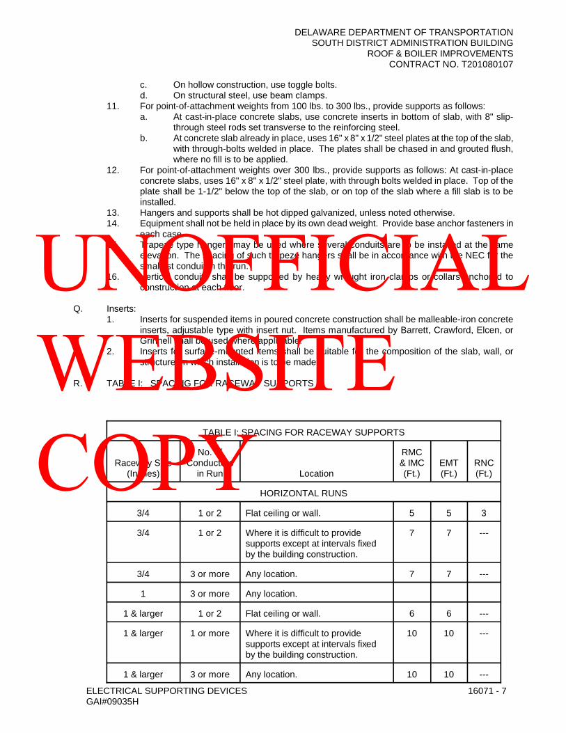
DELAWARE DEPARTMENT OF TRANSPORTATIONSOUTH DISTRICT ADMINISTRATION BUILDING
ROOF & BOILER IMPROVEMENTSCONTRACT NO. T201080107
ELECTRICAL SUPPORTING DEVICES 16071 - 7GAI#09035H
c. On hollow construction, use toggle bolts.d. On structural steel, use beam clamps.
11. For point-of-attachment weights from 100 lbs. to 300 lbs., provide supports as follows:a. At cast-in-place concrete slabs, use concrete inserts in bottom of slab, with 8" slip-
through steel rods set transverse to the reinforcing steel.b. At concrete slab already in place, uses 16" x 8" x 1/2" steel plates at the top of the slab,
with through-bolts welded in place. The plates shall be chased in and grouted flush, where no fill is to be applied.
12. For point-of-attachment weights over 300 lbs., provide supports as follows: At cast-in-place concrete slabs, uses 16" x 8" x 1/2" steel plate, with through bolts welded in place. Top of the plate shall be 1-1/2" below the top of the slab, or on top of the slab where a fill slab is to be installed.
13. Hangers and supports shall be hot dipped galvanized, unless noted otherwise.14. Equipment shall not be held in place by its own dead weight. Provide base anchor fasteners in
each case.15. Trapeze type hangers may be used where several conduits are to be installed at the same
elevation. The spacing of such trapeze hangers shall be in accordance with the NEC for the smallest conduit in the run.
16. Vertical conduits shall be supported by heavy wrought iron clamps or collars anchored to construction at each floor.
Q. Inserts:1. Inserts for suspended items in poured concrete construction shall be malleable-iron concrete
inserts, adjustable type with insert nut. Items manufactured by Barrett, Crawford, Elcen, or Grinnell shall be used where applicable.
2. Inserts for surface-mounted items shall be suitable for the composition of the slab, wall, or structure on which installation is to be made.
R. TABLE I: SPACING FOR RACEWAY SUPPORTS
TABLE I: SPACING FOR RACEWAY SUPPORTS
Raceway Size(Inches)
No. of Conductors
in Run Location
RMC & IMC (Ft.)
EMT (Ft.)
RNC (Ft.)
HORIZONTAL RUNS
3/4 1 or 2 Flat ceiling or wall. 5 5 3
3/4 1 or 2 Where it is difficult to provide supports except at intervals fixed by the building construction.
7 7 ---
3/4 3 or more Any location. 7 7 ---
1 3 or more Any location.
1 & larger 1 or 2 Flat ceiling or wall. 6 6 ---
1 & larger 1 or more Where it is difficult to provide supports except at intervals fixed by the building construction.
10 10 ---
1 & larger 3 or more Any location. 10 10 ---
UNOFFICIAL WEBSITE COPY

DELAWARE DEPARTMENT OF TRANSPORTATIONSOUTH DISTRICT ADMINISTRATION BUILDING
ROOF & BOILER IMPROVEMENTSCONTRACT NO. T201080107
ELECTRICAL SUPPORTING DEVICES 16071 - 8GAI#09035H
TABLE I: SPACING FOR RACEWAY SUPPORTS
Raceway Size(Inches)
No. of Conductors
in Run Location
RMC & IMC (Ft.)
EMT (Ft.)
RNC (Ft.)
Any --- Concealed. 10 10 ---
VERTICAL RUNS
3/4 --- Exposed. 7 7 ---
1, 1-1/4 --- Exposed. 8 8 ---
1-1/2 & larger --- Exposed. 10 10 ---
Up to 2 --- Shaftway. 14 10 ---
2-1/2 --- Shaftway. 16 10 ---
3 & larger --- Shaftway. 20 10 ---
Any --- Concealed. 10 10 ---
Abbreviations: EMT Electrical Metallic Tubing
IMC Intermediate Metallic Conduit
RMC Rigid Metallic Conduit
3.3 CLEANUP
A. Upon completion of this section of work, remove all protective wraps and debris. Repair any damage due to installation of this section of work.
3.4 PROTECTION
A. During installation, it shall be the responsibility of the installer to protect this work from damage.
B. Upon completion of this scope of work, it shall become the responsibility of the General Contractor to protect this work from damage during the remainder of construction on the project and until substantial completion.
END OF SECTION 16071
UNOFFICIAL WEBSITE COPY

DELAWARE DEPARTMENT OF TRANSPORTATIONSOUTH DISTRICT ADMINISTRATION BUILDING
ROOF & BOILER IMPROVEMENTSCONTRACT NO. T201080107
ELECTRICAL IDENTIFICATION 16075 - 1GAI#09035H
SECTION 16075 - ELECTRICAL IDENTIFICATION
PART 1 - GENERAL
1.1 RELATED DOCUMENTS
A. Drawings, General and Supplementary Provisions of the contract, including but not limited to Section 100 of the DelDOT Standard Specifications for Road and Bridge Construction apply to this section.
1.2 SUMMARY
A. This Section includes electrical identification materials and devices required to comply with ANSI C2, NFPA 70, OSHA standards, and authorities having jurisdiction.
B. This section includes labeling of all terminations and related subsystems; including, but not limited to, nameplates, stenciling, wire and cable markers, labeling and identification of cables, equipment and other products.
1.3 SUBMITTALS
A. Product Data: For each electrical identification product indicated.
B. Schedule of Nomenclature: An index of electrical equipment and system components used in identification signs and labels. Provide a schedule of nameplates and stenciling.
C. Samples: Prior to installation, the Contractor shall submit samples for each type of label and sign to illustrate color, lettering style, and graphic features of identification products. These samples shall include examples of the lettering to be used. Samples shall be mounted on 8-1/2" x 11" sheets annotated, explaining their proposed use.
1.4 QUALITY ASSURANCE
A. Comply with ANSI C2.
B. Comply with NFPA.
C. Comply with ANSI A13.1 and NFPA 70 for color-coding.
D. Comply with applicable EIA/TIA Standards.
E. Comply with OSHA Standards, including OSHA 1910 ARC Flash Standards.
1.5 DEFINITIONS
A. Emergency systems include, but are not limited to, generator circuits and systems, fire alarm systems, exit sign circuits, emergency lighting circuits, etc.
PART 2 - PRODUCTS
2.1 RACEWAY AND CABLE LABELS
A. Comply with ANSI A13.1, Table 3, for minimum size of letters for legend and for minimum length of color field for each raceway and cable size.
1. Color: Black letters on orange field.2. Legend: Indicates voltage and service.
UNOFFICIAL WEBSITE COPY
DELAWARE DEPARTMENT OF TRANSPORTATIONSOUTH DISTRICT ADMINISTRATION BUILDING
ROOF & BOILER IMPROVEMENTSCONTRACT NO. T201080107
ELECTRICAL IDENTIFICATION 16075 - 2GAI#09035H
B. Adhesive Labels: Preprinted, flexible, self-adhesive vinyl with legend overlaminated with a clear, weather- and chemical-resistant coating.
C. Pretensioned, Wraparound Plastic Sleeves: Flexible, preprinted, color-coded, acrylic band sized to suit the diameter of the line it identifies and arranged to stay in place by pretensioned gripping action when placed in position.
D. Colored Adhesive Tape: Self-adhesive vinyl tape not less than 3 mils thick by 1 to 2 inches wide(0.08 mm thick by 25 to 51 mm wide), in appropriate colors for system voltage and phase.
E. Underground-Line Warning Tape: Permanent, bright-colored, continuous-printed, vinyl tape.1. Not less than 6 inches wide by 4 mils thick (152 mm wide by 0.102 mm thick).2. Compounded for permanent direct-burial service.3. Embedded continuous metallic strip or core.4. Printed legend indicating type of underground line.
F. Tape Markers: Vinyl or vinyl-cloth, self-adhesive, wraparound type with preprinted numbers and letters.
G. Aluminum, Wraparound Marker Bands: Bands cut from 0.014-inch- (0.4-mm-) thick aluminum sheet, with stamped or embossed legend, and fitted with slots or ears for permanently securing around wire or cable jacket or around groups of conductors.
H. Plasticized Card-Stock Tags: Vinyl cloth with preprinted and field-printed legends. Orange background, unless otherwise indicated, with eyelet for fastener.
I. Aluminum-Faced, Card-Stock Tags: Weather-resistant, 18-point minimum card stock faced on both sides with embossable aluminum sheet, 0.002 inch (0.05 mm) thick, laminated with moisture-resistant acrylic adhesive, punched for fasteners, and preprinted with legends to suit each application.
J. Brass or Aluminum Tags: 2 by 2 by 0.05-inch (51 by 51 by 1.3-mm) metal tags with stamped legend, punched for fastener.
2.2 NAMEPLATES AND SIGNS
A. Safety Signs: Comply with 29 CFR, Chapter XVII, Part 1910.145, OSHA, and NFPA.
B. Engraved Plastic Nameplates and Signs: Engraving stock, melamine 3-layer plastic laminate, minimum 1/8 inch (3.2 mm) thick for larger sizes. Minimum 3/8” high lettering. Use colors prescribed by ANSI A13.1, NFPA 70, OSHA, and these specifications.
1. Engraved legend with black background with white core, with beveled edges.2. Punched or drilled for mechanical fasteners.3. Emergency system nameplates shall have an engraved legend with white letters on red
background, or as required by the local authority having jurisdiction.4. All lettering shall be uppercase.
C. Baked-Enamel Signs for Interior Use: Preprinted aluminum signs, punched or drilled for fasteners, with colors, legend, and size required for the application. 1/4-inch (6.4-mm) grommets in corners for mounting.
D. Exterior, Metal-Backed, Butyrate Signs: Weather-resistant, nonfading, preprinted, cellulose-acetate butyrate signs with 0.0396-inch (1-mm) galvanized-steel backing; and with colors, legend, and size required for the application. Use 1/4-inch (6.4-mm) grommets in corners for mounting.
E. Fasteners for Nameplates and Signs: Self-tapping, stainless-steel screws or No. 10/32, stainless-steel machine screws with nuts and flat and lock washers.
UNOFFICIAL WEBSITE COPY

DELAWARE DEPARTMENT OF TRANSPORTATIONSOUTH DISTRICT ADMINISTRATION BUILDING
ROOF & BOILER IMPROVEMENTSCONTRACT NO. T201080107
ELECTRICAL IDENTIFICATION 16075 - 3GAI#09035H
2.3 MISCELLANEOUS IDENTIFICATION PRODUCTS
A. Cable Ties: Fungus-inert, self-extinguishing, one-piece, self-locking, Type 6/6 nylon cable ties.1. Minimum Width: 3/16 inch (5 mm).2. Tensile Strength: 50 lb (22.3 kg) minimum.3. Temperature Range: Minus 40 to plus 185 deg F (Minus 40 to plus 85 deg C).4. Color: According to color-coding.
B. Paint: Formulated for the type of surface and intended use.1. Primer for Galvanized Metal: Single-component acrylic vehicle formulated for galvanized
surfaces.2. Primer for Concrete Masonry Units: Heavy-duty-resin block filler.3. Primer for Concrete: Clear, alkali-resistant, binder-type sealer.4. Enamel: Silicone-alkyd or alkyd urethane as recommended by primer manufacturer.
C. Stenciling: Use black paint. Emergency system stenciling shall use red paint.
PART 3 - EXECUTION
3.1 INSTALLATION
A. General:1. Where mixed voltages are used in one building (e.g., 480 volts, 208 volts), each switch,
switchboard, junction box, equipment, etc., on each system must be labeled for voltage in addition to other requirements listed herein.
2. All branch circuit and power panels must be identified with the same symbol used in the circuit directory in the main distribution center.
3. Before attaching labels, clean all surfaces with the label manufacturer’s recommended cleaning agent.
4. Install all labels firmly, as recommended by the label manufacturer.5. Labels attached to data or Communication patch panels and faceplates shall be installed
plumb and neatly on all equipment.6. Install nameplates parallel to equipment lines.7. Secure nameplates to equipment fronts using screws or rivets. Secure nameplate to inside
of recessed panelboards in finished locations.8. Embossed tape will not be permitted for any application.9. Stenciling may only be used on equipment fronts in unfinished areas or in areas
designated by the Engineer.10. Labels: All labels shall be permanent and be machine-generated. NO HANDWRITTEN OR
NON-PERMANENT LABELS SHALL BE ALLOWED.11. Label size shall be appropriate for the conductor size. All labels to be used shall be self-
laminating, white/transparent vinyl and be wrapped around the cable. Flag type labels are not allowed. The labels shall be of adequate size to accommodate the circumference of the cable being labeled and properly self-laminated over the full extent of the printed area of the label.
B. Panelboard Directories: Accurate, typed index directories for panels shall be covered with clear plastic, have a metal frame, and should be spelled out in Specifications. Room numbers on directories shall be Owner’s numbers, not plan numbers, unless Owner so specifies. Directories shall comply with NEC and identify specific location and exact type of load for each circuit breaker.
1. Panelboards shall be equipped with 1/16" thick laminated phenolic nameplates with white letters (minimum 1/4” high) on black background and shall have beveled edges. Include the following information:a. Panel (Description) b. Served From (Designation) c. Circuit (Number) , Located (Location
UNOFFICIAL WEBSITE COPY

DELAWARE DEPARTMENT OF TRANSPORTATIONSOUTH DISTRICT ADMINISTRATION BUILDING
ROOF & BOILER IMPROVEMENTSCONTRACT NO. T201080107
ELECTRICAL IDENTIFICATION 16075 - 4GAI#09035H
2. The Contractor shall provide up to date directories, in both new and existing panels, indicating all deletions and additions, and to note the date of all changes on the directory.
3. The directory shall reflect the actual room numbers. Directories indicating the reference room numbers on the contract drawings or in the panelboard schedule shall not be acceptable.
4. If at any time after occupancy the directory is found to be incorrect due to negligence by the installer, then the Contractor shall trace out circuits and correct the directory at no additional cost to the Owner.
C. Miscellaneous Identification:1. Individual circuit breakers, switches, and motor starters in panelboards, switchboards, and
motor control centers: 1/4-inch (6 mm); identify circuit and load served, including location.2. Individual circuit breakers, enclosed switches, and motor starters: 1/4-inch (6 mm); identify
load served.3. Junction boxes: 1/2-inch (13 mm); identify system source(s) and load(s) served.
D. Identification Materials and Devices: Install at locations for most convenient viewing without interference with operation and maintenance of equipment.
E. Lettering, Colors, and Graphics: Coordinate names, abbreviations, colors, and other designations with corresponding designations in the Contract Documents or with those required by codes and standards. Use consistent designations throughout Project.
F. Sequence of Work: If identification is applied to surfaces that require finish, install identification after completing finish work.
G. Self-Adhesive Identification Products: Clean surfaces before applying.
H. Install painted identification according to manufacturer's written instructions and as follows:1. Clean surfaces of dust, loose material, and oily films before painting.2. Prime surfaces using type of primer specified for surface.3. Apply one intermediate and one finish coat of enamel.
I. Color Code Banding and painting of Raceways, Boxes, and Cables: Band all exposed and concealed accessible raceways, pull boxes, and junction boxes of the systems listed below:
1. Bands: Pretensioned, wraparound plastic sleeves; colored adhesive tape; or a combination of both. Make each color band 2 inches (51 mm) wide, completely encircling conduit, and place adjacent bands of two-color markings in contact, side by side.
2. Band Locations: At changes in direction, at penetrations of walls and floors, at 50-foot (15-m) maximum intervals in straight runs, and at 25-foot (7.6-m) maximum intervals in congested areas.
3. Junction boxes, pull boxes, and their covers shall be distinctively painted to identify their service.
4. Apply the following colors to the systems listed below:a. Fire Alarm System: Red.b. Mechanical and Electrical Supervisory System: Green and blue.c. 120/208 V Power and Lighting System: Yellow.d. 480/277 V Power and Lighting System: Black.e. Standby/Emergency Power System: Orange.
J. Caution Labels for Indoor Boxes and Enclosures for Power and Lighting: Install pressure-sensitive, self-adhesive labels identifying system voltage with black letters on orange background. Install on exterior of door or cover.
K. Circuit Identification Labels on Boxes: Install labels externally.
UNOFFICIAL WEBSITE COPY

DELAWARE DEPARTMENT OF TRANSPORTATIONSOUTH DISTRICT ADMINISTRATION BUILDING
ROOF & BOILER IMPROVEMENTSCONTRACT NO. T201080107
ELECTRICAL IDENTIFICATION 16075 - 5GAI#09035H
1. Exposed Boxes: Pressure-sensitive, self-adhesive plastic label on cover.2. Concealed Boxes: Plasticized card-stock tags.3. Labeling Legend: Permanent, waterproof listing of panel and circuit number or equivalent.
L. Secondary Service, Feeder, and Branch-Circuit Conductors: Color-code throughout the secondary electrical system.
1. Color-code 208/120-V system as follows:a. Phase A: Black.b. Phase B: Red.c. Phase C: Blue.d. Neutral: White.e. Ground: Green.
2. Color-code 480/277-V system as follows:a. Phase A: Brown.b. Phase B: Orange.c. Phase C: Yellow.d. Neutral: Gray.e. Ground: Green.
3. Factory apply color the entire length of conductors, except the following field-applied, color-coding methods may be used instead of factory-coded wire for sizes larger than No. 10 AWG:a. Colored, pressure-sensitive plastic tape in half-lapped turns for a distance of 6
inches (150 mm) from terminal points and in boxes where splices or taps are made. Apply last two turns of tape with no tension to prevent possible unwinding. Use 1-inch- (25-mm-) wide tape in colors specified. Adjust tape bands to avoid obscuring cable identification markings.
b. Colored cable ties applied in groups of three ties of specified color to each wire at each terminal or splice point starting 3 inches (76 mm) from the terminal and spaced 3 inches (76 mm) apart. Apply with a special tool or pliers, tighten to a snug fit, and cut off excess length.
M. Power-Circuit and Control Wire Identification: Metal tags or aluminum, wraparound marker bands for each conductor, cables, feeders, and power circuits in vaults, panelboard gutters, outlet boxes, junction boxes, pullboxes, junction boxes, manholes, switchboard rooms, and at load connections. Identify with branch circuit or feeder number for power and lighting circuits and with control wire number as indicated on equipment manufacturer’s shop drawings for control wiring.
1. Legend: 1/4-inch- (6.4-mm-) steel letter and number stamping or embossing with legend corresponding to indicated circuit designations.
2. Tag Fasteners: Nylon cable ties.3. Band Fasteners: Integral ears.
N. Apply identification to conductors as follows:1. Conductors to Be Extended in the Future: Indicate source and circuit numbers.2. Multiple Power or Lighting Circuits in the Same Enclosure: Identify each conductor with
source, voltage, circuit number, and phase. Use color-coding to identify circuits' voltage and phase.
3. Multiple Control and Communication Circuits in the Same Enclosure: Identify each conductor by its system and circuit designation. Use a consistent system of tags, color-coding, or cable marking tape.
O. Apply warning, caution, and instruction signs as follows:1. Warnings, Cautions, and Instructions: Install to ensure safe operation and maintenance of
electrical systems and of items to which they connect. Install engraved plastic-laminated instruction signs with approved legend where instructions are needed for system or equipment operation. Install metal-backed butyrate signs for outdoor items.
UNOFFICIAL WEBSITE COPY

DELAWARE DEPARTMENT OF TRANSPORTATIONSOUTH DISTRICT ADMINISTRATION BUILDING
ROOF & BOILER IMPROVEMENTSCONTRACT NO. T201080107
ELECTRICAL IDENTIFICATION 16075 - 6GAI#09035H
2. Emergency Operation: Install engraved laminated signs with white legend on red background with emergency instructions on power transfer, load shedding, and other emergency operations.
P. Equipment Identification Labels: Engraved plastic laminate. Install on each unit of equipment, including central or master unit of each system. This includes power, lighting, communication, signal, and alarm systems, unless units are specified with their own self-explanatory identification. Unless otherwise indicated, provide a single line of text with 1/2-inch- (13-mm-) high lettering on 1-1/2-inch- (38-mm-) high label; where two lines of text are required, use labels 2 inches (50 mm) high. Use white lettering on black field. Identify equipment designations, voltage rating, and source. Apply labels for each unit of the following categories of equipment using mechanical fasteners:
1. Panelboards, electrical cabinets, and enclosures. Identify equipment designations, voltage rating, and source.
2. Access doors and panels for concealed electrical items.3. Disconnect switches.4. Enclosed circuit breakers.5. Motor starters.6. Push-button stations.7. Contactors.8. Control devices.
Q. Communication Conduit and Cables1. Cables shall be identified with Brady vinyl cloth B-500 or equivalent by L.E.M., Stranco, or
Panduit wire markers. Conduit shall be identified with Brady Vinyl Cloth B-500 pipe markers or equivalent. Systems shall be identified as follows:a. Each cable shall be identified at each point of entrance to or exit from a conduit or
enclosure and at 50-foot intervals in the tray. All identification at 50-foot intervals shall be at the same location in the tray. Each cable shall be identified at control panels, junction boxes, and terminal boards.
b. Conduit shall be identified exiting an enclosure or panel at junction or pull boxes, and at each side of penetrations of walls, partitions, or floors, with 1-foot of penetration.
2. Provide metal or aluminum wrap-around marker bands for each cable group at entrance and exit of each enclosure, closet, manhole, and handhole.
R. Fire Alarm: Junction box covers shall be painted red. Wiring color code shall match existing. Wiring color code shall be as follows:
1. Red - Smoke Detector - Common.2. Black - Smoke Detector - Power.3. Yellow - Smoke Detector - Alarm.4. Orange - Heat Detector - Alarm.5. Pink - Flow Switch.6. Tan - Valve Tamper Switch.7. Purple - Bells.8. Grey - Audio/Visual Devices.9. Light Blue - Manual Stations.
S. Provide NEC, ANSI, and OSHA-approved “DANGER - HIGH VOLTAGE” warning signs on all doors of dedicated electrical rooms or closets. Where doors are located in finished areas, locate sign on the inside of the door. Coordinate mounting requirements with the Engineer. Minimum sign dimension shall be 15" x 11".
T. Provide labels on all electrical switchboards, motor control centers, panels, and associated electrical equipment with the appropriate ARC Flash Rating per OSHA 29 and NFPA 70E.
U. Surfaces shall be cleaned and painted, if specified, before applying markings.
UNOFFICIAL WEBSITE COPY
DELAWARE DEPARTMENT OF TRANSPORTATIONSOUTH DISTRICT ADMINISTRATION BUILDING
ROOF & BOILER IMPROVEMENTSCONTRACT NO. T201080107
ELECTRICAL IDENTIFICATION 16075 - 7GAI#09035H
V. Place markings so that they are visible from the floor.
W. Protect finished identification to insure that markings are clear and legible when project is turned over to the Owner.
END OF SECTION 16075
UNOFFICIAL WEBSITE COPY
DELAWARE DEPARTMENT OF TRANSPORTATIONSOUTH DISTRICT ADMINISTRATION BUILDING
ROOF & BOILER IMPROVEMENTSCONTRACT NO. T201080107
ELECTRICAL FIRESTOPPING 16090 - 1GAI#09035H
SECTION 16090 - ELECTRICAL FIRESTOPPING
PART 1 - GENERAL
1.1 RELATED DOCUMENTS
A. Drawings, General and Supplementary Provisions of the contract, including but not limited to Section 100 of the DelDOT Standard Specifications for Road and Bridge Construction apply to this section.
1.2 SUMMARY
A. Section includes:1. Through-penetration firestopping in fire rated construction.2. Through-penetration smoke-stopping in smoke partitions.
B. Related items: Raceway seals and manufactured electrical devices: Refer to Section 16100.
1.3 REFERENCES
A. Underwriters Laboratories1. UL Fire Resistance Directory
a. Through-penetration firestop devices (XHCR)b. Fire resistance rating (BXUV)c. Through-penetration firestop systems (XHEZ)d. Fill, void, or cavity material (XHHW)
B. American Society for Testing and Materials Standards: ASTM E 814-88: Standard Test Method for Fire Tests of Through-Penetration Firestops.
1.4 DEFINITIONS
A. Assembly: Particular arrangement of materials specific to given type of construction described or detailed in referenced documents.
B. Barriers: Time-rated fire walls, smoke barrier walls, time rated ceiling/floor assemblies and structural floors.
C. Firestopping: Methods and materials applied in penetrations and unprotected openings to limit spread of heat, fire, gasses and smoke.
D. Penetration: Opening or foreign material passing through or into barrier or structural floor such that full thickness of rated materials is not obtained.
E. System: Specific products and applications, classified and numbered by Underwriters Laboratories, Inc. to close specific barrier penetrations.
F. Sleeve: Metal fabrication or pipe section extended through thickness of barrier and used to permanently guard penetration. Sleeves are described as part of penetrating system in other sections and mayor maynot be required.
1.5 SYSTEM DESCRIPTION
A. Design Requirements1. Fire-rated construction: Maintain barrier and structural floor fire resistance ratings including
resistance to cold smoke at all penetrations, connections with other surfaces or types of
UNOFFICIAL WEBSITE COPY

DELAWARE DEPARTMENT OF TRANSPORTATIONSOUTH DISTRICT ADMINISTRATION BUILDING
ROOF & BOILER IMPROVEMENTSCONTRACT NO. T201080107
ELECTRICAL FIRESTOPPING 16090 - 2GAI#09035H
construction, at separations required to permit building movement and sound or vibration absorption.
2. Smoke barrier construction: Maintain barrier and structural floor resistance to cold smoke at all penetrations, connections with other surfaces and types of construction and at all separations required to permit building movement and sound or vibration absorption.
1.6 SUBMITTALS
A. Submit in accordance with Section 16010, unless otherwise indicated.
B. Product data: Manufacturer's specifications and technical data including the following:1. Detailed specification of construction and fabrication.2. Manufacturer's installation instructions.
C. Shop drawings: Indicate dimensions, description of materials and finishes, general construction, specific modifications, component connections, anchorage methods, hardware, and installation procedures, plus the following specific requirements.
1. Details of each proposed assembly identifying intended products and applicable UL system number, or UL classified devices.
2. Manufacturer or manufacturer's representative shall provide qualified engineering judgment and drawings relating to non-standard applications as needed.
D. Quality control submittals: Statement of qualifications.
E. Applicators' qualifications statement: List past projects indicating required experience.
1.7 QUALITY ASSURANCE
A. Installer's qualifications: Fire experienced in installation or application of systems similar in complexity to those required for this project, plus the following:
1. Acceptable to or licensed by manufacturer, State or local authority where applicable.2. At least 2 years experience with systems.3. Successfully completed at least 5 comparable scale projects using this system.
B. Local and State regulatory requirements: Submit forms or acceptance for proposed assemblies not conforming to specific UL Firestop System numbers, or UL classified devices.
C. Materials shall have been tested to provide fire rating at least equal to that of the construction.
D. Manufacturer shall be a member of the International Firestop Council (IFC).
1.8 DELIVERY, STORAGE, AND HANDLING
A. Packing and shipping:1. Deliver products in original unopened packaging with legible manufacturer's identification.2. Coordinate delivery with scheduled installation date, allow minimum storage at site.
B. Storage and protection: Store materials in a clean, dry, ventilated location. Protect from soiling, abuse, moisture and freezing when required. Follow manufacturer's instructions.
1.9 PROJECT CONDITIONS
A. Existing conditions:
1. Verify existing conditions and substrates before starting work. Correct unsatisfactory conditions before proceeding.
UNOFFICIAL WEBSITE COPY

DELAWARE DEPARTMENT OF TRANSPORTATIONSOUTH DISTRICT ADMINISTRATION BUILDING
ROOF & BOILER IMPROVEMENTSCONTRACT NO. T201080107
ELECTRICAL FIRESTOPPING 16090 - 3GAI#09035H
2. Proceed with installation only after penetrations of the substrate and supporting brackets have been installed.
B. Environmental requirements:1. Furnish adequate ventilation if using solvent.2. Furnish forced air ventilation during installation if required by manufacturer.3. Keep flammable materials away from sparks or flame.4. Provide masking and drop cloths to prevent contamination of adjacent surfaces by firestopping
materials.
1.10 GUARANTEE
A. Submit copies of written guarantee agreeing to repair or replace joint sealers which fall in joint adhesion, extrusion resistance, migration resistance, or general durability or appear to deteriorate in any other manner not clearly specified by submitted manufacturer's data as an inherent quality of the material for the exposure indicated. The guarantee period shall be two year from date of substantial completion unless otherwise noted.
PART 2 - PRODUCT
2.1 MANUFACTURERS
A. Subject to compliance with requirements, manufacturers offering products that may be incorporated into the work include, but are not limited to, the following:
1. Hilti.2. Nelson.
2.2 THROUGH-PENETRATION FIRESTOPPING OF FIRE-RATED CONSTRUCTION
A. Systems of devices listed in the UL Fire Resistance Directory under categories XHCR and XHEZ may be used, providing that it conforms to the construction type, penetrant type, annular space requirements and fire rating involved in each separate instance, and that the system be symmetrical for wall applications. Systems or devices must be asbestos-free.
1. Additional requirements: Withstand the passage of cold smoke either as an inherent property of the system, or by the use of a separate product included as a part of the UL system or device, and designed to perform this function.
2. Acceptable manufacturers and products.a. Those listed in the UL Fire Resistance directory for the UL System involved and as
further defined in the System and Applications Schedule in Part 3.6 of this section.b. All firestopping products must be from a single manufacturer. All trades shall use
products from the same manufacturer unless otherwise noted.
2.3 SMOKE-STOPPING AT SMOKE PARTITIONS
A. Through-penetration smoke-stopping: Any system complying with the requirements for through-penetration firestopping in fire-rated construction, as specified in The Systems and Applications Schedule in Part 3.6 of this section, is acceptable, provided that the system includes the specified smoke seal or will provide a smoke seal. The length of time of the fire resistance may be disregarded.
2.4 ACCESSORIES
A. Fill, void or cavity materials: As classified under category XHHW in the UL Fire Resistance Directory.
B. Forming materials: As classified under category XHKU in the UL Fire Resistance Directory.
C. Sleeves: Minimum 24 MSG galvanized steel, 12" diameter or smaller steel pipe. Sleeve shall project 1/2" from each surface of the floor/wall. Size as recommended by firestop manufacturer.
UNOFFICIAL WEBSITE COPY

DELAWARE DEPARTMENT OF TRANSPORTATIONSOUTH DISTRICT ADMINISTRATION BUILDING
ROOF & BOILER IMPROVEMENTSCONTRACT NO. T201080107
ELECTRICAL FIRESTOPPING 16090 - 4GAI#09035H
PART 3 - EXECUTION
3.1 EXAMINATION
A. Verification of conditions: Examine areas and conditions under which work is to be performed and identify conditions detrimental to proper or timely completion.
1. Verify barrier penetrations are properly sized and in suitable condition for application of materials.
2. Do not proceed until unsatisfactory conditions have been corrected.
3.2 PREPARATION
A. Clean surfaces to be in contact with penetration seal materials of dirt, grease, oil, loose materials, rust, or other substances that may affect proper fitting, adhesion, or the required fire resistance.
3.3 INSTALLATION
A. Install penetration seal materials in accordance with printed instructions of the UL Fire Resistance Directory and in accordance with manufacturer's instruction.
B. Seal holes or voids made by penetrations to ensure an effective smoke barrier.
C. Protect materials from damage on surfaces subject to traffic.
D. When large openings are created in walls or floors to permit installation of conduits, cable tray, or other items, close unused portions of opening with firestopping materials tested for the application. See UL Fire Resistance Directory or Section 3.6 of this document.
E. Install smoke stopping as specified for firestopping.
F. Provide sleeves the full thickness of the assembly being penetrated and cut sleeves to a length of 1"more than the over-all thickness of the penetration, or as recommended by the firestop manufacturer.
G. All holes and voids shall be sealed the same day they are made.
3.4 FIELD QUALITY CONTROL
A. Examine penetration sealed areas to ensure proper installation before concealing or enclosing areas.
B. Keep areas of work accessible until inspection by applicable code authorities.
C. Perform under this section patching and repairing of firestopping caused by cutting or penetration by other trades.
3.5 ADJUSTING AND CLEANING
A. Clean up spills of liquid components.
B. Neatly cut and trim materials as required.
C. Remove equipment, materials and debris, leaving area in undamaged, clean condition.
3.6 SYSTEMS AND APPLICATION SCHEDULES*
SEE NEXT PAGE.
UNOFFICIAL WEBSITE COPY

DELAWARE DEPARTMENT OF TRANSPORTATIONSOUTH DISTRICT ADMINISTRATION BUILDING
ROOF & BOILER IMPROVEMENTSCONTRACT NO. T201080107
ELECTRICAL FIRESTOPPING 16090 - 5GAI#09035H
PENETRATING ITEM
CONCRETE GYPSUM WOOD FLOOR/ CEILING
Metal Pipe CAJ1001 CP25S/L, CP25N/SCAJ1006 CS-195+, FS-195+CAJ1007 FS-195+, 1"& 2" WideCAJ1009 2000, 2000+, 2003CAJ1010 2000, 2000+, 2003CAJ1012 2000, 2000+, 2003CAJ1013 2000, 2000+, 2003CAJ1014 2000, 2000+, 2003CAJ1015 2000, 2000+, 2003CAJ1017 FD 150CAJ1021 FD 150CAJ1027 MPS-2+CAJ1044 CP 25WB+CAJ1052 CP 25S/L, CP 25N/SCAJ1058 2000, 2000+, 2003CAJ1060 2000, 2000+, 2003CAJ1063 2000, 2000+, 2003CAJ1066 CP 25N/S,CP 25S/L, CP 25WB+CAJ1091 CP 25N/S,CP 25S/L, CP 25WB+CAJ1092 CP 25WB+CAJ1112 FS-195+CAJ1160 CP 25S/L, CP 25N/SCAJ1175 CP 25WB+CAJ1176 CP 25WB+CAJ1188 2000+
CBJ1020 CS-195+, FS-195+CBJ1021 CS-195+, MPS-2+CBJ1031 2001CBJ1032 2001
FA1002 CP 25WB+
WJ1010 CP 25WB+WJ1023 2001
WL1001 CP 25WL1002 FS-195+WL1003 CP 25WB+,CP 25N/SWL1008 2000+WL1009 2000+WL1010 2000+WL1016 CP 25WB+WL1017 CP 25WB+,CP 25N/SWL1032 CP 25WB+,CP 25N/SWL1036 FD 150WL1037 CS-195+,FS-195+WL1067 CP 25N/SWL1073 CP 25WB+WL1080 MPS-2+WL1082 2000+
FC1002 CP 25FC1003 2000,2000+,20003FC1006 CP 25WB+
Non-Metallic CAJ2001 FS-195+, 1"& 2" WIDE, PPD'SCAJ2002 FS-195+CAJ2003 CS-195+, FS-195+CAJ2005 FS-195+CAJ2006 FS-195+CAJ2013 FS-195+CAJ2019 2000, 2000+, 2003CAJ2027 FS-195+, CP 25N/S, CP 25S/L,
CP 25WB+CAJ2028 FS-195, MPS-2+CAJ2029 FS-195+, PPD'SCAJ2030 CS-195+, FS-195+CAJ2040 FS-195+, CP 25WB+CAJ2044 FS-195+, CP 25N/S, CP 25S/L
CP 25 WB+CAJ2090 FS-195+CAJ2177 FS-195+, PPD'S
FA2001 FS-195+, PPD'SFS2002 CS-195+, FS-195+, MPS-2+, PPD'SFA2011 FS-195+
WJ2012 FS-195+ 1" WIDE
WL2002 FS-195+, PPD'SWL2003 FS-195+WL2004 FS-195+WL2005 FS-195+ 4' WIDEWL2006 FS-195+WL2013 FS-195+WL2031 CS-195+, FS-195+WL2032 CS-195+, FS-195+WL2033 FS-195+WL2073 FS-195+ 1" WIDE
FC2002 FS-195+, PPD'SFC2007 FS-195+, PPD'SFC2008 FS-195+FC2009 FS-195+, PPD'SFC2024 FS-195+FC2026 FS-195+FC2028 FS-195+, 1' &
2" WIDE, PPD'S
UNOFFICIAL WEBSITE COPY

DELAWARE DEPARTMENT OF TRANSPORTATIONSOUTH DISTRICT ADMINISTRATION BUILDING
ROOF & BOILER IMPROVEMENTSCONTRACT NO. T201080107
ELECTRICAL FIRESTOPPING 16090 - 6GAI#09035H
PENETRATING ITEM
CONCRETE GYPSUM WOOD FLOOR/ CEILING
InsulatedCable
CAJ3001 CP 25N/S, CP 25S/LCAJ3005 CS 195+, FS-195+CAJ3007 2001CAJ3009 2000, 2000+, 2003CAJ3010 2000, 2000+, 2003CAJ3011 2001CAJ3014 FD 150CAJ3015 FD 150CAJ3021 MPS-2+CAJ3029 2000, 2000+, 2003CAJ3030 CP 25WB+CAJ3031 CP 25N/S, CP 25S/LCAJ3041 2000, 2000+, 2003CAJ3044 CS-195+, FS-195+CAJ3058 FS-195+, MPS-2+CAJ3071 CP 25N/S, CP 25S/LCAJ3074 CP 25N/S, CP 25S/LCAJ3075 2001CAJ3080 CP 25WB+
CBJ3016 CS-195+, FS-195+CBJ3017 CS-195+, MPS-2+
FA3001 CP 25WB+
FB3004 CS-195+, MP
WJ3015 2001WJ3016 2001
WL3001 CP 25, MPS-2+WL3008 2000+WL3009 2000+WL3015 CP 25WB+, CP 25N/SWL3022 2000+WL3030 FS-195+WL3031 MPS-2+WL3032 CP 25WB+WL3041 2000+WL3051 CP 25N/SWL3056 CP25N/SWL3062 CP 25WB+
FC3001 CP 25S/L, CP 25N/SFC3002 2000+FC3003 2000, 2000+, 20003FC3007 CP 25WB+, MPS-2+FC3008 FS-195+
MixedPenetrating Items Combos
CAJ8001 CS-195+ FS-195+CAJ8003 2000, 2000+, 20003CAJ8004 2000, 2000+, 20003CAJ8006 2001CAJ8013 FS-195+, CP 25
CBJ8004 CS-195, FS-195+CBJ8005 CS-195+, MPS-2+CBJ8008 2001
FA8001 FS-195+, CP 25WB+
WL8002 CS-195+, FS-195+
* Underwriter's Laboratories, Inc., Fire Resistance Directory.
END OF SECTION 16090
UNOFFICIAL WEBSITE COPY
DELAWARE DEPARTMENT OF TRANSPORTATIONSOUTH DISTRICT ADMINISTRATION BUILDING
ROOF & BOILER IMPROVEMENTSCONTRACT NO. T201080107
CONDUCTORS AND CABLES 16120 - 1GAI#09035H
SECTION 16120 - CONDUCTORS AND CABLES
PART 1 – GENERAL
1.1 RELATED DOCUMENTS
A. Drawings, General and Supplementary Provisions of the contract, including but not limited to Section 100 of the DelDOT Standard Specifications for Road and Bridge Construction apply to this section.
1.2 SUMMARY
A. This Section includes building wires and cables and associated connectors, splices, and terminations for wiring systems rated 600 V and less.
1.3 SUBMITTALS
A. Field Test Reports: Indicate and interpret test results for compliance with performance requirements. Indicate procedures and values obtained.
B. Submit product data. Provide for each cable assembly type, wire, cables, conductors, and connectors.
C. Submit factory test reports. Indicate procedures and values obtained.
D. Submit shop drawings for modular wiring system including layout of distribution devices, branch circuit conduit and cables, circuiting arrangement, and outlet devices.
E. Submit manufacturer’s installation instructions. Indicate application conditions and limitations of use stipulated by product testing agency specified under Regulatory Requirements.
F. Project Record Documents: Record actual locations of components and circuits.
1.4 QUALITY ASSURANCE
A. Testing Agency Qualifications: In addition to requirements specified in Section "Quality Control," an independent testing agency shall meet OSHA criteria for accreditation of testing laboratories, Title 29, Part 1907; or shall be a full-member company of the International Electrical Testing Association.
1. Testing Agency's Field Supervisor: Person currently certified by the International Electrical Testing Association or the National Institute for Certification in Engineering Technologies, to supervise on-site testing specified in Part 3.
B. Listing and Labeling: Provide wires and cables specified in this Section that are listed and labeled.1. The Terms "Listed" and "Labeled": As defined in NFPA 70, Article 100.2. Listing and Labeling Agency Qualifications: A "Nationally Recognized Testing Laboratory" as
defined in OSHA Regulation 1910.7.
C. Comply with NEMA/Insulated Cable Engineers Association (ICEA) Standards.
D. Comply with NECA Standard of Installation.
E. Comply with NETA ATS - Acceptance Testing Specifications for Electrical Power Distribution Equipment and Systems.
F. American Society for Testing and Materials (ASTM): Comply with requirements of the following:1. B1 - Standard Specification for Hard-Drawing Copper Wire2. B2 - Standard Specification for Medium-Hard-Drawn Copper Wire3. B3 - Standard Specification for Soft or Annealed Copper Wire
UNOFFICIAL WEBSITE COPY

DELAWARE DEPARTMENT OF TRANSPORTATIONSOUTH DISTRICT ADMINISTRATION BUILDING
ROOF & BOILER IMPROVEMENTSCONTRACT NO. T201080107
CONDUCTORS AND CABLES 16120 - 2GAI#09035H
4. B8 - Standard Specification for Concentric-Lay-Stranded Copper conductors, Hard, Medium-Hard, or Soft
5. D753 - Standard Specification for General Purpose Polychloroprene Jacket for Wire and Cable
G. Electrical Testing Laboratories (ETL): Provide wiring, cabling and connector products which are ETL listed and labeled.
H. Institute of Electrical and Electronics Engineers (IEEE): Comply with the following standards which apply to wiring systems:
1. 82 - Test procedure for Impulse Voltage Tests on Insulated Conductors2. 241 - Recommended Practice for Electric Power Systems in Commercial Buildings
I. NFPA: Comply with NFPA 70 requirements for construction, installation and color-coding of electrical wire, cable and connections.
J. National Electrical Manufactures Association (NEMA): Comply with requirements of the following:1. WC3 - Rubber-Insulated Wire and Cable for the Transmission and Distribution of
Electrical Energy2. WC5 - Thermoplastic-Insulated Wire and Cable for the Transmission and Distribution
of Electrical Energy
K. UL: Provide material conforming to the following standards:1. 83 Thermoplastic-Insulated Wires and Cables.2. 486A Wire Connectors and Soldering Lugs for Use with Copper Conductors
L. UL Labels: Provide wiring, cabling and connector products which are UL listed and labeled.
1.5 DELIVERY, STORAGE, AND HANDLING
A. Deliver wires and cables according to NEMA WC 26, “Wire and Cable Packaging”.
B. Storage: Store wire and cable in a clean dry space in original containers. Protect products from weather, damaging fumes, construction debris and traffic.
C. Handling: Handle wire and cable carefully to avoid abrading, puncturing and tearing wire and cable insulation and sheathing. Ensure that dielectric resistance integrity of wires/cables is maintained.
1.6 COORDINATION
A. Coordinate layout and installation of cables with other installations.
B. Revise locations and elevations from those indicated, as required to suit field conditions and as approved by Engineer.
C. Determine required separation between cable and other work.
D. Determine cable routing to avoid interference with other work.
E. Revise locations and elevations from those indicated as required to suit field conditions and as approved by the Engineer.
F. Wire and cable routing indicated is approximate. Where wire and cable destination is indicated and routing is not shown, the Contractor shall determine exact routing and lengths required.
UNOFFICIAL WEBSITE COPY
DELAWARE DEPARTMENT OF TRANSPORTATIONSOUTH DISTRICT ADMINISTRATION BUILDING
ROOF & BOILER IMPROVEMENTSCONTRACT NO. T201080107
CONDUCTORS AND CABLES 16120 - 3GAI#09035H
1.7 PROJECT CONDITIONS
A. Verify that field measurements are as shown on the Drawings.
B. Conductor sizes are based on copper.
C. Wire and cable routing shown on Drawings is approximate unless dimensioned. Route wire and cable as required to meet Project Conditions.
D. Where wire and cable routing is not shown, and destination only is indicated, determine exact routing and lengths required.
PART 2 - PRODUCTS
2.1 MANUFACTURERS
A. Available Manufacturers: Subject to compliance with requirements, manufacturers offering products that may be incorporated into the Work include, but are not limited to, the following:
1. Wires and Cables:a. American Insulated Wire Corp.; Leviton Manufacturing Co.b. BICC Brand-Rex Company.c. Carol Cable Co., Inc.d. Southwire Company.
2. Connectors and Accessories for Wires and Cables:a. AMP Incorporated.b. Buchanan.c. General Signal; O-Z/Gedney Unit.d. Monogram Company; AFC.e. NSI Industries, Inc.f. Square D Company; Anderson.g. 3M Company; Electrical Products Division.
2.2 BUILDING WIRES AND CABLES
A. UL-listed building wires and cables with conductor material, insulation type, cable construction, and rating as specified in Part 3 "Wire and Insulation Applications" Article.
B. Rubber Insulation Material: Comply with NEMA WC 3.
C. Thermoplastic Insulation Material: Comply with NEMA WC 5.
D. Cross-Linked Polyethylene Insulation Material: Comply with NEMA WC 7.
E. Ethylene Propylene Rubber Insulation Material: Comply with NEMA WC 8.
F. Conductor Material: Copper.
G. Stranding: Solid conductor for No. 10 AWG and smaller; stranded conductor for larger than No. 10 AWG.
H. Conductor: Single conductor annealed copper type.
I. Insulation Voltage Rating: 600 Volts.
UNOFFICIAL WEBSITE COPY
DELAWARE DEPARTMENT OF TRANSPORTATIONSOUTH DISTRICT ADMINISTRATION BUILDING
ROOF & BOILER IMPROVEMENTSCONTRACT NO. T201080107
CONDUCTORS AND CABLES 16120 - 4GAI#09035H
J. Conductivity: Minimum of 98% at 20-degrees C (68-degrees F) or maximum resistivity of 1.7 micro-ohms per centimeter.
K. Forbidden Cables: Use of BX (armored) cable, UF, and Romex cable is NOT PERMITTED.
2.3 CONNECTORS AND SPLICES
A. UL-listed, factory-fabricated wiring connectors of size, ampacity rating, material, type, and class for application and service indicated. Comply with Project's installation requirements and as specified in Part 3 "Wire and Insulation Applications" Article.
B. Split Bolt Connectors: Blackburn Type H Model.
C. Solderless Pressure Connectors: High copper alloy terminal. May be used only for cable termination to equipment pads or terminals. Not approved for splicing.
D. Spring Wire Connectors: Solderless spring type pressure connector with insulating covers for copper wire splices and taps. Use for conductor sizes 10 AWG and smaller.
E. All wire connectors used in underground or exterior pull boxes shall be gel-filled twist connectors or a connector designed for damp and wet locations.
F. Mechanical Connectors: Bolted type tin-plated; high conductivity copper alloy; spacer between conductors; beveled cable entrances.
G. Compression (crimp) Connectors: Long barrel; seamless, tin-plated electrolytic high conductivity copper tubing, internally beveled barrel ends. Connector shall be clearly marked with the wire size and type and proper number and location of crimps.
H. Heat shrinkable tubing shall meet the requirements of ANSI C119.1-1986 for buried connections to 90°C and shall be material flame-retarded per IEEE 383 “Vertical Tray Flame Test”. Motor connection kits shall consist of heat-shrinkable, polymeric insulating material over the connection area and a high dielectric strength mastic to seal the ends against ingress of moisture and contamination. Motor connection kits shall accommodate a range of cable sizes for both in-line and stub-type configurations. Connection kits shall be independent of cable manufacturer’s tolerances.
I. Wire Nut Connectors:1. Wire nuts installed in wet locations, exterior, etc., shall be self-contained, waterproof and
corrosion-proof units incorporating prefilled silicone grease to block out moisture and air.2. Connectors shall be UL listed and appropriately sized according to manufacturer=s
recommendation for the suitable wire sizes and voltage rating (600 volt minimum).3. Connector body shall have a color-coded outer shell.4. Connectors shall be as manufactured by King Technology or approved equal.
2.4 INSULATING TAPE, PUTTY, RESIN AND SUPPORTS
A. Tape: Provide plastic electrical insulating tape which is flame-retardant, cold and weather-resistant. Tape for use in areas subject to temperatures 30°C to 105°C, or where the tape will be subjected to an oil splash, tape shall have a minimum thickness of 8.5 mils, and shall consist of an oil-resistant acrylic adhesive.
B. Materials: Provide all insulating materials for splices and connections such as glass and synthetic tapes, putties, resins, splice cases, or compositions of the type approved for the particular use, location, voltage and temperature and apply and install in an approved manner, all in accordance with the manufacturer’s recommendations.
UNOFFICIAL WEBSITE COPY

DELAWARE DEPARTMENT OF TRANSPORTATIONSOUTH DISTRICT ADMINISTRATION BUILDING
ROOF & BOILER IMPROVEMENTSCONTRACT NO. T201080107
CONDUCTORS AND CABLES 16120 - 5GAI#09035H
C. Supports: Provide cable supports of the wedge type which firmly clamp each individual cable and tighten due to the cable weight.
2.5 MC CABLE
A. MC cable shall be allowed for connections within a room from a junction box to the lighting fixtures.
B. Conduit home runs shall be in EMT.
C. MC cable shall be allowed form a junction box within a room to the receptacles in the same room.
D. MC cable shall not be allowed to cross one room to another room whether the wall between two rooms goes up to slab or not. If the rooms are identified as two separate rooms, MC cable shall not be used between the two rooms.
E. MC cable shall not be used, between two receptacles when they are in two separate rooms, on the same wall.
PART 3 - EXECUTION
3.1 EXAMINATION
A. Examine raceways and building finishes to receive wires and cables for compliance with requirements for installation tolerances and other conditions affecting performance of wires and cables. Do not proceed with installation until unsatisfactory conditions have been corrected.
B. By beginning work, the Contractor accepts conditions and assumes responsibility for correcting unsuitable conditions encountered at no additional cost to the Owner.
3.2 PREPARATION
A. Completely and thoroughly swab raceway before installing wire.
3.3 WIRE AND INSULATION APPLICATIONS
A. Building wire, unless otherwise indicated shall be 600 volt, 90-degrees C, Type THHN/THWN for #10AWG wire and smaller, and Type THHN/THWN or XHHW for #8 AWG wire and larger for interior use, and Type THWN insulation for underground or exterior installations outside building installation. Conductors shall be soft drawn copper of not less than 98% conductivity.
B. Stranded conductors: Feeders, branch circuits larger than #10 AWG, all control circuit conductors.
C. No branch circuit wires smaller than #12 AWG shall be used unless otherwise indicated. Conductors shall be continuous from outlet to outlet and from terminal board to point of final connection, and no splice shall be made except within outlet or junction boxes. All conductors shall be of the size indicated. All wires #8 AWG and larger shall be stranded.
D. Control wiring shall not be less than #14 AWG and shall be color-coded using colors impregnated into the insulation. All wiring, contacts, and terminal blocks shall be suitably tagged for ease in identification and tracing of circuits. Identification tags shall be engraved fiber or plastic type, subject to acceptance. Wires shall be numbered and coded, using Brady "Quicklabels", or equal.
E. Service entrance cable shall be Type USE, copper conductors, rubber insulation with neoprene cover, single conductor per UL 493.
UNOFFICIAL WEBSITE COPY

DELAWARE DEPARTMENT OF TRANSPORTATIONSOUTH DISTRICT ADMINISTRATION BUILDING
ROOF & BOILER IMPROVEMENTSCONTRACT NO. T201080107
CONDUCTORS AND CABLES 16120 - 6GAI#09035H
F. A color-coding system, as listed below or as required by Code and local laws and ordinances, shall be used throughout the building's network of feeders and circuits and used as a basis of balancing the load.Selection shall be based on applicable work covered by this contract.
UNOFFICIAL WEBSITE COPY

DELAWARE DEPARTMENT OF TRANSPORTATIONSOUTH DISTRICT ADMINISTRATION BUILDING
ROOF & BOILER IMPROVEMENTSCONTRACT NO. T201080107
CONDUCTORS AND CABLES 16120 - 7GAI#09035H
SYSTEMCOLOR
Phase A Phase B Phase C Neutral Ground208Y/120V Black Red Blue White* Green480Y/277V Brown Orange Yellow Gray* Green*See NEC Par. 200-6, 200-7, 210-4, 210-5, and 310-12 for combined system requirements.
1. Wiring in sizes up to #8 AWG shall have colored insulation. Wiring in sizes #6 AWG and larger shall be coded by colored tape for 6 inches of insulation on both ends of conductor. The wiring shall be tagged at terminations, and in pull boxes, hand holes, and manholes.
2. All emergency wiring shall have the same color-coding, but shall clearly be identified as emergency in all outlets, fixtures, etc. All emergency wiring shall be installed in a dedicated conduit system.
3. Switch leg wire shall be labeled with “S” tag.
G. All control wiring shall be color coded with wires of colors different from those used to designate phase wires.
H. Wiring for general 15 and 20 amp 120 volt and 277 volt branch circuit work shall be as follows unless otherwise indicated:
HOME RUN LENGTH AND WIRE SIZE CIRCUIT LENGTH AND WIRE SIZE120 Volt 277 Volt 120 Volt 277 Volt
0 – 60’ #12 0 – 175’ #12 0 – 100’ #12 0 – 200’ #1260 – 100’ #10 175 – 350’ #10 100’ & Up #10 200’ & Up #10100’ & Up #8 350’ & Up #8
Circuit length as given above shall be the wire length between the first and last outlet on the circuit. Home run length as given above shall be the wire length between the first outlet and the panelboard. In accordance with the above, where the size of branch circuit conductors is increased by the minimum required by the NEC for the branch circuit rating, it is the Contractor’s responsibility to insure that the termination provisions of all equipment connected to such circuits are listed as suitable for the conductor sizes involved.
I. Joints of #10 AWG and smaller shall be made with properly insulated solderless type pressure connectors. Where stranded conductors or multiple solid conductors are connected to terminals, solderless lugs manufactured by Thomas and Betts Company or equivalent shall be used.
J. Joints of #8 AWG and larger in power and lighting circuits shall be of the type indented into the conductor by means of a hand or hydraulic pressure tool. Connectors shall be Burndy "Hy-dent", T&B "Sta-Kon", or equivalent. Connectors for control wiring shall be Burndy "Hy-Lug", or equivalent.
K. All circuits for exterior electric work shall be #10 AWG (minimum) and contain an extra #10 AWG (minimum) copper ground conductor. All exterior wiring shall be installed in conduit as specified above, unless otherwise noted on the Drawings.
3.4 INSTALLATION
A. Install wires and cables as indicated, according to manufacturer's written instructions and NECA's "Standard of Installation."
B. Remove existing wires from raceway before pulling in new wires and cables.
UNOFFICIAL WEBSITE COPY
DELAWARE DEPARTMENT OF TRANSPORTATIONSOUTH DISTRICT ADMINISTRATION BUILDING
ROOF & BOILER IMPROVEMENTSCONTRACT NO. T201080107
CONDUCTORS AND CABLES 16120 - 8GAI#09035H
C. Pull Conductors: Use a UL-listed and manufacturer-approved pulling compound or lubricant where necessary; compound used must not deteriorate conductor or insulation. Do not exceed manufacturer's recommended maximum pulling tensions and sidewall pressure values.
D. Use pulling means, including fish tape, cable, rope, and basket-weave wire/cable grips, that will not damage cables or raceway. Completely and thoroughly swab conduit system before installing conductors.
E. Install exposed cables, parallel and perpendicular to surfaces of exposed structural members, and follow surface contours where possible.
F. Support cables according to Specification Sections "Basic Electrical Materials and Methods" and “Electrical Supporting Devices”.
G. Seal around cables penetrating fire-rated elements according to Section "Firestopping," and Section “Electrical Firestopping”.
H. Identify wires and cables according to Electrical Section "Electrical Identification."
I. Conductors installed in parallel shall be of equal lengths.
J. No conductors less than #10 AWG shall be installed in exterior underground conduit.
K. Wiring at Outlets: Install with at least 12 inches (300 mm) of slack conductor at each outlet.
L. Connect outlets and components to wiring and to ground as indicated and instructed by manufacturer. Tighten connectors and terminals, including screws and bolts, according to equipment manufacturer’s published torque-tightening values for equipment connectors. Where manufacturer’s torquing requirements are not indicated, tighten connectors and terminals according to tightening torques specified in UL Standard 486A.
M. The Contractor shall provide suitable installation equipment to prevent cutting and abrasion of conductor insulation. The Contractor shall use suitable cable guides, pulleys, and protective sleeving to prevent damage to cable during installation. Ropes used for pulling of wire and cable shall be made of polyethylene or other suitable non-metallic material. Pulling lines shall be attached to cable by means of either woven basket grips or pulling types attached directly to the conductors. Wire pulling lubricants, if used, shall conform to UL requirements applicable to the various insulations and raceway materials. The lubricants shall be certified by the manufacturer to be non-injurious to such insulation and materials.
N. Each feeder cable shall be labeled at terminals and at all accessible points in equipment and in pull boxes. Each control wire shall be labeled at both ends. Labels shall be self-sticking wire markers.
O. Riser cables shall have cable supports as required by Code.
P. For other installations, for rubber and plastic-covered wire and cable, pulling compound Ideal Yellow 77 may be used.
Q. Terminal lugs for wires #8 AWG and larger shall be T&B 54,000 Series or Burndy “HY-Dent”, compression type, unless noted otherwise. One-hole lugs for #4/0 AWG and smaller. Two-hole lugs for all sizes #250 kcmil AWG and larger.
R. Install wires and cables using braided rope larger than the cable being pulled to keep twists to a minimum.
S. Provide an insulated green ground wire with the feeder wiring for all three phase feeders shown or not shown. Equipment ground wire (size per NEC) shall be provided for all circuits in PVC conduit.
UNOFFICIAL WEBSITE COPY

DELAWARE DEPARTMENT OF TRANSPORTATIONSOUTH DISTRICT ADMINISTRATION BUILDING
ROOF & BOILER IMPROVEMENTSCONTRACT NO. T201080107
CONDUCTORS AND CABLES 16120 - 9GAI#09035H
T. Each circuit serving dedicated receptacle(s) identified on the drawings for computer use shall be isolated ground type and shall have a separate green equipment grounding conductor which shall be connected to backboxes, metal raceway, etc., and a separate green and yellow striped isolated ground conductor connected to the panel isolated ground bus and to the receptacle’s separate isolation grounding terminal.
U. Where conductors are shown on the plans to be direct-buried, they shall be 2, 3, or 4 conductors each, with separate self-contained ground conductor, cable type UF or USE.
V. General: Install electrical cables, wires, and connectors as indicated in compliance with manufacturer’s written instructions, applicable requirements of NEC and NECA’s “Standard of Installation”, and in accordance with recognized industry practices.
W. Coordinate cable and wire installation work with electrical raceway and equipment installation work, as necessary for proper interface.
X. Conductors installed in runs within 6 inches of heating pipes or equipment shall be type AVA. No conductors shall be drawn into conduit until all work, which may cause cable damage, is completed.
Y. All wiring over boilers and breechings, in fluorescent fixture channels, in Kitchen hoods, and in other high ambient temperature areas, shall be of types required by NEC.
Z. During installation, do not deform cable by improper bending, stretching, twisting, kinking, or pinching, nor do any other abusive handling. Any failure to observe these instructions will be detected and corrected during the demonstrations following completion of the installation. All cable runs shall contain “S” loops or other means to accommodate expansion or contraction as required. Cable bends will have a radius not less than the value recommended by the cable manufacturer. Cable connected to electronic equipment in the system shall be tagged to show its function and the location of its other end. All labels shall be of durable material and securely fastened to the cable.
3.5 CONNECTIONS
A. Conductor Splices: Keep to minimum.
B. Install splices and tapes that possess equivalent or better mechanical strength and insulation ratings than conductors being spliced.
C. Use splice and tap connectors compatible with conductor material.
D. Connect outlets and components to wiring and to ground as indicated and instructed by manufacturer.
E. Tighten electrical connectors and terminals according to manufacturer's published torque-tightening values. If manufacturer's torque values are not indicated, use those specified in UL 486A.
F. Wire splices and taps shall be adequate to carry full current rating of wire.
G. Splices and taps in wires up to #8 AWG shall be made with “Scotch-lok” or T&B PT Series or Ideal Wing Nut insulated electrical connectors. Wire nuts installed in wet location boxes shall be silicon gel-filled. For wires #8 AWG and larger, use copper solderless connectors covered with insulating molded body and then wrapped with electrical tape. Use twist-on wire connectors for connecting lighting fixtures and small motor leads up to #8 AWG wire.
H. Conductors shall be continuous from outlet to outlet, and no splices shall be made except within outlet or junction boxes. Junction boxes may be utilized where required. Wire connectors of insulating material or solderless pressure connections, properly taped, shall be utilized for all splices in wiring.
UNOFFICIAL WEBSITE COPY

DELAWARE DEPARTMENT OF TRANSPORTATIONSOUTH DISTRICT ADMINISTRATION BUILDING
ROOF & BOILER IMPROVEMENTSCONTRACT NO. T201080107
CONDUCTORS AND CABLES 16120 - 10GAI#09035H
I. Splices in branch circuits and feeders shall be made where indicated or as required for the installation. All splices shall be accessible and made in enclosure approved for that purpose.
J. For splices in branch circuits and feeders, provide connectors as follows:
1. Wire Sizes #14 AWG to #10 AWG: Provide Ideal Model 74B or 76B or equivalent by T&B.2. Wire Sizes #8 AWG and Larger: Provide Ideal Model Series AGP-/Size/and GT-/Size/ or
equivalent by Burndy, O-Z, or T&B. All splices shall be enclosed in insulating molded thermoplastic, rubber, or rubber-like covers or shall be wrapped with Bishop No. 111 or equivalent insulating tape in accordance with the Manufacturer’s directions.
K. Thoroughly clean wiring prior to installing lugs or connectors.
3.6 IDENTIFICATION
A. Interface with Other Work:
1. Identify wire and cable using Thomas and Betts Type WM vinyl markers.2. Identify each conductor with its circuit number or other designation indicated on the Drawings in
all junction, pull, terminal boxes, and cabinets. Identify neutrals with common circuit numbers in all junction, pull and terminal boxes, panels and cabinets.
B. Provide identification tags on each conductor entering panel, switch, junction box, and pull boxto identify conductor.
C. Comply with the requirements of Section 16075 “Electrical identification”.
D. Feeder Identification: Securely fasten nonferrous identifying tags or pressure-sensitive labels to all cables, feeders, and power circuits in vaults, pull boxes, manholes, switchboard rooms and at termination of cables.
1. Tags or labels shall be stamped or printed to correspond with markings on drawings or marked so that feeder or cable may be readily identified.
2. If suspended type tags are provided, they shall be attached by approximately 55-pound test monofilament line or slip-free plastic cable lacing units.
3.7 FIELD QUALITY CONTROL
A. Testing Agency: Engage a qualified independent testing agency to perform field quality-control testing.
B. Testing: On installation of wires and cables and before electrical circuitry has been energized, demonstrate product capability and compliance with requirements.
1. Procedures: Perform each visual and mechanical inspection and electrical test stated in NETA ATS, Section 7.3.1. Certify compliance with test parameters.
C. Remove malfunctioning conductors and cables and replace with new units and retest to demonstrate compliance. Use of tapes and sleeves over damaged insulation shall not be acceptable, unless approved in writing by the Owner.
D. Measure tightness of bolted connections and compare torque measurements with manufacturer’s recommended values.
E. Verify continuity of each branch circuit conductor.
F. Tests: Feeders and branch circuit insulation shall be tested after installation, and before connection to fixtures and appliance.
UNOFFICIAL WEBSITE COPY
DELAWARE DEPARTMENT OF TRANSPORTATIONSOUTH DISTRICT ADMINISTRATION BUILDING
ROOF & BOILER IMPROVEMENTSCONTRACT NO. T201080107
CONDUCTORS AND CABLES 16120 - 11GAI#09035H
1. Tests shall be performed with a 500-volt megger, and conductors shall test free from short-circuits and grounds.
2. Conductors shall be tested phase-to-phase and phase-to-ground.3. Furnish the instruments, materials, and labor required. Perform the tests in the presence of the
Contracting Officer.
4. Test readings shall be recorded and delivered.
G. Demonstration: Subsequent to wire and cable hook-ups, energize circuit and demonstrate functioning in accordance with requirements. Where necessary, correct malfunctioning units, and then retest to demonstrate compliance.
END OF SECTION 16120UNOFFICIAL WEBSITE COPY

DELAWARE DEPARTMENT OF TRANSPORTATIONSOUTH DISTRICT ADMINISTRATION BUILDING
ROOF & BOILER IMPROVEMENTSCONTRACT NO. T201080107
RACEWAYS AND BOXES 16130 - 1GAI#09035H
SECTION 16130 - RACEWAYS AND BOXES
PART 1 - GENERAL
1.1 RELATED DOCUMENTS
A. Drawings, General and Supplementary Provisions of the contract, including but not limited to Section 100 of the DelDOT Standard Specifications for Road and Bridge Construction apply to this section.
1.2 SUMMARY
A. This Section includes raceways, fittings, boxes, enclosures, and cabinets for electrical wiring.1. Raceways include the following:
a. RMC.b. IMC.c. EMT.d. FMC.e. LFMC.f. RNC.g. Wireways.
2. Boxes, enclosures, and cabinets include the following:a. Device boxes.b. Outlet boxes.c. Pull and junction boxes.d. Cabinets and hinged-cover enclosures.
3. Miscellaneous Products include the following:a. Expansion/Deflection fittings.b. Bushings.
B. Related Sections include the following:1. Specification Section "Electrical Firestopping."2. Specification Section "Electrical Supporting Devices" for raceways and box supports.3. Specification Section "Wiring Devices" for devices installed in boxes and for floor-box service
fittings.
1.3 DEFINITIONS
A. EMT: Electrical metallic tubing.
B. FMC: Flexible metal conduit.
C. IMC: Intermediate metal conduit.
D. LFMC: Liquidtight flexible metal conduit.
E. RMC: Rigid metal conduit.
F. RNC: Rigid nonmetallic conduit.
1.4 SUBMITTALS
A. Product Data: For raceways, wireways and fittings, hinged-cover enclosures, and cabinets.
B. Shop Drawings: Include layout drawings showing components and wiring for nonstandard boxes, enclosures, and cabinets.
UNOFFICIAL WEBSITE COPY
DELAWARE DEPARTMENT OF TRANSPORTATIONSOUTH DISTRICT ADMINISTRATION BUILDING
ROOF & BOILER IMPROVEMENTSCONTRACT NO. T201080107
RACEWAYS AND BOXES 16130 - 2GAI#09035H
1.5 QUALITY ASSURANCE
A. Listing and Labeling: Provide raceways and boxes specified in this Section that are listed and labeled.1. The Terms "Listed" and "Labeled": As defined in NFPA 70, Article 100.2. Listing and Labeling Agency Qualifications: A "Nationally Recognized Testing Laboratory" as
defined in OSHA Regulation 1910.7.
B. Comply with NECA's "Standard of Installation" and NECA 101 “Recommended Practice for Installing Steel Conduits”.
C. Comply with NFPA 70.
1.6 COORDINATION
A. Coordinate layout and installation of raceways and boxes with other construction elements to ensure adequate headroom, working clearance, and access.
B. Verify routing and termination locations of conduits and boxes prior to rough-in.
C. Conduit routing shown on Drawings is only approximate and diagrammatic. Route conduits as required for a complete conduit and wiring system.
D. Coordinate installation of outlet boxes, mounting heights, orientation, and locations of outlets.
1.7 PROJECT RECORD DOCUMENTS:
A. Accurately record routing of all concealed conduits. Record actual routing of all exposed conduits/larger than 1 inch. Indicate actual locations and mounting heights of outlets, pull and junction boxes, branch circuits, arrangements, etc.
PART 2 - PRODUCTS
2.1 MANUFACTURERS
A. Available Manufacturers: Subject to compliance with requirements, manufacturers offering products that may be incorporated into the Work include, but are not limited to, the following:
1. Metal Conduit and Tubing:a. Allied Tube & Conduit Corporation.b. Anamet, Inc.; Anaconda Metal Hose.c. AFC/Monogram Company.d. Carol Cable Co., Inc.e. Cole-Flex Corp.f. Electri-Flex Co.g. Flexcon, Inc.; Coleman Cable Systems, Inc.h. Grinnell Co.; Allied Tube and Conduit Div.i. Monogram Co.; AFC.j. Spiraduct, Inc.k. Triangle PWC, Inc.l. Wheatland Tube Co.
2. Conduit Bodies and Fittings:a. American Electric; Construction Materials Group.b. Crouse-Hinds; Div. of Cooper Industries.c. Emerson Electric Co.; Appleton Electric Co.d. Hubbell, Inc.; Killark Electric Manufacturing Co.e. Lamson & Sessions; Carlon Electrical Products.
UNOFFICIAL WEBSITE COPY

DELAWARE DEPARTMENT OF TRANSPORTATIONSOUTH DISTRICT ADMINISTRATION BUILDING
ROOF & BOILER IMPROVEMENTSCONTRACT NO. T201080107
RACEWAYS AND BOXES 16130 - 3GAI#09035H
f. O-Z/Gedney; Unit of General Signal.g. Scott Fetzer Co.; Adalet-PLM.h. Spring City Electrical Manufacturing Co.i. Thomas & Betts Corporation.
3. Metal Wireways:a. Hoffman Engineering Co.b. Keystone/Rees, Inc.c. Square D Co.
4. Boxes, Enclosures, and Cabinets:a. American Electric; FL Industries.b. Butler Manufacturing Co.; Walker Division.c. Crouse-Hinds; Div. of Cooper Industries.d. Electric Panelboard Co., Inc.e. Erickson Electrical Equipment Co.f. Hoffman Engineering Co.; Federal-Hoffman, Inc.g. Hubbell Inc.; Killark Electric Manufacturing Co.h. Hubbell Inc.; Raco, Inc.i. Lamson & Sessions; Carlon Electrical Products.j. O-Z/Gedney; Unit of General Signal.k. Parker Electrical Manufacturing Co.l. Robroy Industries, Inc.; Electrical Division.m. Scott Fetzer Co.; Adalet-PLM.n. Spring City Electrical Manufacturing Co.o. Thomas & Betts Corp.p. Woodhead Industries, Inc.; Daniel Woodhead Co.
2.2 METAL CONDUIT AND TUBING
A. Rigid Galvanized Steel Conduit: ANSI C80.1 and UL 6.
B. IMC: ANSI C80.6.
C. EMT and Fittings: ANSI C80.3, galvanized tubing.1. Fittings: Compression type, NEMA FB1.
D. FMC: Zinc-coated steel.
E. LFMC: Flexible steel conduit with PVC jacket.
F. Fittings: NEMA FB 1; compatible with conduit/tubing materials.
2.3 METAL WIREWAYS
A. Material: Sheet metal sized and shaped as indicated.
B. Fittings and Accessories: Include couplings, offsets, elbows, expansion joints, adapters, hold-down straps, end caps, and other fittings to match and mate with wireways as required for complete system.
C. Select features, unless otherwise indicated, as required to complete wiring system and to comply with NFPA 70.
D. Wireway Covers: Screw-cover type.
E. Finish: Manufacturer's standard enamel finish.
2.4 OUTLET AND DEVICE BOXES
UNOFFICIAL WEBSITE COPY
DELAWARE DEPARTMENT OF TRANSPORTATIONSOUTH DISTRICT ADMINISTRATION BUILDING
ROOF & BOILER IMPROVEMENTSCONTRACT NO. T201080107
RACEWAYS AND BOXES 16130 - 4GAI#09035H
A. Sheet Metal Boxes: NEMA OS 1, galvanized flat-rolled sheet steel.
B. Cast-Metal Boxes: NEMA FB 1, Type FD, cast box, deep type, with gasketed cover, and threaded hubs.
C. Outlet Box Accessories: Provide outlet box accessories as required for each installation, including corrosion-resistant screws, mounting brackets, wallboard hangers, extension rings, fixture studs, cable clamps, and metal straps for supporting outlet boxes which are compatible with outlet boxes being used and fulfilling requirements of individual wiring situations.
D. Nonmetallic: NEMA OS2.
2.5 PULL AND JUNCTION BOXES
A. Small Sheet Metal Boxes: NEMA OS 1.
B. Sheet metal boxes over 12" in any dimension shall comply with the requirements of 16130 - 2.10 “Enclosures and Cabinets”.
C. Boxes for Outdoor and Wet Locations: Flat flanged, surface-mounted, UL listed as raintight, galvanized cast iron box and cover with neoprene gasket and stainless steel cover screws.
D. Boxes for Buried Flush Grade Locations: NEMA 250, Type 6, flat flanged, UL listed as watertight, galvanized cast iron, aluminum or PVC box.
1. Cover: Nonskid cover with neoprene gasket and stainless steel cover screws.2. Cover Legend: “Electric” or “Communications” as appropriate.
2.6 BOX EXTENSIONS
A. Prohibited on new construction.
2.7 ENCLOSURES AND CABINETS
A. Hinged-Cover Enclosures: NEMA 250, Type 1 in dry locations, and Type 4 in wet or damp locations, with continuous hinge cover and flush latch.
1. Metal Enclosures: Steel, finished inside and out with manufacturer's standard enamel.
B. Cabinets: NEMA 250, Type 1, galvanized steel box with removable interior panel and removable front, finished inside and out with manufacturer's standard enamel. Hinged door in front cover with flush latch and concealed hinge. Key latch to match panelboards. Include metal barriers to separate wiring of different systems and voltage, and include accessory feet where required for freestanding equipment.
2.8 EXPANSION / DEFLECTION FITTINGS
A. Provide an expansion/deflection fitting in each concealed or exposed electrical run crossing a building expansion joint. Fittings shall be complete with bronze end couplings, neoprene sleeve, tinned copper braid integral bonding jumper and stainless steel bands. Expansion/deflection fittings shall be suitable for the size and type of conduit run they connect. Bonding jumper shall comply with NEC and UL requirements.
B. Expansion/deflection fitting shall accommodate the following movements without collapsing or fracturing the conduit and damaging the wires it contains:
1. Axial expansion or contraction up to 3/4-inch.2. Angular misalignment of the axes of the conduits up to 30 degrees in all directions.3. Parallel misalignment of the axes of the conduits up to 3/4-inch in all directions.
UNOFFICIAL WEBSITE COPY

DELAWARE DEPARTMENT OF TRANSPORTATIONSOUTH DISTRICT ADMINISTRATION BUILDING
ROOF & BOILER IMPROVEMENTSCONTRACT NO. T201080107
RACEWAYS AND BOXES 16130 - 5GAI#09035H
C. Expansion/Deflection fitting shall be OZ/Gedney Type “DX” or approved equal by Crouse Hinds (Type XD).
2.9 BUSHINGS
A. Bushings for 1-inch conduit and smaller shall be self-extinguishing thermoplastic type - 150°C temperature rating.
B. Bushings for 1-1/4" conduit and larger shall be malleable iron body with 150°C insulating ring. Insulating material shall be locked in place and non-removable.
PART 3 - EXECUTION
3.1 EXAMINATION
A. Examine surfaces to receive raceways, boxes, enclosures, and cabinets for compliance with installation tolerances and other conditions affecting performance of raceway installation. Do not proceed with installation until unsatisfactory conditions have been corrected.
3.2 RACEWAY REQUIREMENTS
A. Conduit:
CONDUIT APPLICATION SCHEDULE
CONDUIT APPLICATION REQUIREMENT
Rigid galvanized steel conduit. (RGS)
Under concrete slab.
Rigid galvanized steel conduit. (RGS)
Exposed exterior locations. Use threaded or raintight fittings.
Rigid galvanized steel conduit. (RGS)
Wet interior locations. Use threaded or raintight fittings.
Rigid galvanized steel conduit (RGS).
Exposed dry interior locations up to 7'-0" AFF.
Where subject to damage.
Electrical Metallic Tubing(EMT).
Concealed dry interior locations.
Electrical Metallic Tubing (EMT). Exposed dry interior locations above 7'-0" AFF.
Liquidtight flexible metallic conduit.
Equipment Connections. Short lengths only.(Maximum 6 feet)
Rigid non-metallic conduit (Schedule 40 PVC Type II).
Exterior underground. Except where rigid metal conduit is required.
Metal Clad (MC) “Greenfield” Concealed in walls and above-ceilings within rooms.
Not allowed for Home Runs.
1. Provide hot-dip galvanized, rigid steel conduit for medium voltage applications, and for interior work under concrete, and for 2-1/2 inch size and larger.
UNOFFICIAL WEBSITE COPY
DELAWARE DEPARTMENT OF TRANSPORTATIONSOUTH DISTRICT ADMINISTRATION BUILDING
ROOF & BOILER IMPROVEMENTSCONTRACT NO. T201080107
RACEWAYS AND BOXES 16130 - 6GAI#09035H
2. Provide hot-dip galvanized, rigid steel conduit, galvanized intermediate Metal Conduit (IMC) or galvanized Electrical Metallic Tubing (EMT) for concealed work above suspended ceilings and within interior partitions and for exposed interior work above 7'-0". Maximum EMT size permitted is two inches.
3. Provide flexible metal conduit (Greenfield) in short lengths (maximum 6 feet) for the connection for lighting fixtures, dry type transformers and any vibrating equipment. The flexible connections to recessed fixtures and equipment shall be sufficient slack to permit removal of fixture.
4. Provide liquid tight flexible metal conduit (Sealtight) in short length (maximum 6 feet) for the connection of exterior equipment, motors and kitchen equipment.
5. Provide hot-dip galvanized, rigid steel conduit with bonded PVC jacket (Plastic-Bond or Kor-Kap) for work not completely encased in concrete but laid directly in or in contact with ground or on a vapor barrier and additionally, as directed.
6. Aluminum conduit is prohibited.7. Conduits for exterior underground electric work shall be rigid steel, galvanized and sherardized,
leaving the building and to points 5 feet beyond footings. Beyond 5 feet of building, undergroundconduits shall be non-metallic Schedule 40 PVC plastic, Type II.
8. Conduits shall slope from entrance equipment toward outside of building.9. Polyvinyl Chloride (PVC) may be used underground and under slabs except where rigid metal
conduit is required.
B. Fittings:1. All fittings to match conduit material and to be suitable for the purpose intended. Join conduit
with fittings designed and approved for the purpose and make joints tight.2. Provide UL listed compound filled sealing fittings for NEC-required locations, for conduits
passing from interior to exterior, and at the interface of widely different space temperatures suchas refrigeration or cold storage rooms where conduits pass from warm locations to cool locations, such as the boundaries of air conditioned spaces and non-conditioned air spaces. For concealed conduits, install each fitting in a flush steel box with a blank cover plate having a finish similar to that of adjacent plates or surfaces.
3. Provide expansion fittings with bonding jumpers where conduits cross expansion joints or where otherwise required to compensate for thermal expansion and contraction. Provide expansion fittings in each straight uninterrupted run of surface-mounted conduit, both horizontal and vertical, in excess of 200 feet. Distance between fittings shall not exceed 200 linear feet. The Contractor shall refer to the Architectural Drawings for expansion joint locations.
4. Fasten rigid steel conduit with threaded galvanized steel fittings, double locknuts, and insulated bushings. Insulated bushings shall be "OZ" type "B", or equal.
5. Fasten EMT conduit with "Concretight" or "Raintight" compression fittings made from galvanized steel or malleable iron. Fittings using set screw or indentations as a means of attachment are prohibited. All connectors shall have insulated throats.
6. Fasten liquid-tight conduit with fittings incorporating a threaded ferrule, nylon sealing ring, and steel or malleable iron compression nut and body. Furnish Crouse Hinds metallic liquid-tight fittings, or equal.
7. Fasten flexible metallic conduit with T&B "Tite-Bite" insulated connectors, or equal.8. Watertight fittings shall use a copper base anti-corrosive conductive compound. Provide
watertight fittings in conduits exposed to weather, in wet locations, in underground locations, and in slabs.
C. Box Locations:1. Electrical boxes shall accommodate wire pulling, splices, taps, equipment connections and code
compliance.2. Coordinate access doors as required to provide access to boxes in hard ceilings and similar
inaccessible areas.3. Provide cast box (with threaded hubs) in high traffic areas (surface installations), as specified by
Owner.
D. Outlet Boxes:
UNOFFICIAL WEBSITE COPY

DELAWARE DEPARTMENT OF TRANSPORTATIONSOUTH DISTRICT ADMINISTRATION BUILDING
ROOF & BOILER IMPROVEMENTSCONTRACT NO. T201080107
RACEWAYS AND BOXES 16130 - 7GAI#09035H
1. Outlet boxes for concealed work shall be zinc-coated or cadmium-plated sheet steel boxes suitable for the service and type outlet. Boxes and conduit fittings for outdoor and exposed work shall be NEMA 4 cast-aluminum, cast steel or cast iron type with threaded hubs for conduit entrance. Boxes and conduit fittings for outdoor work shall have gasketed cover plates. Extra large boxes shall be provided in accordance with the National Electrical Code where necessary to prevent crowding of wire in the box. Plastic boxes and cast "white metal" boxes classified as NEMA 4 will not be acceptable.
2. Outlet boxes in unplastered brick or block walls shall be provided with deep square-cut device covers. They shall be set so that the brick or block can be cut and fitted closely to the cover opening and so that the standard wall plate will cover the joint between the brick or block and the box.
3. All outlet boxes used for supporting fixtures shall be furnished with malleable iron fixture studs of "no-bolt" type secured by locknut. Provide support for boxes occurring in suspended ceilings.Outlets in ceilings directly on bottom of joists shall be supported independent of ceiling construction. Outlets in suspended ceilings shall not be supported from ceiling construction.
4. All boxes, whether outlet, junction, pull, or equipment, shall be furnished with appropriate covers.
5. No sectionalized boxes shall be used.6. Back-to-back outlet boxes are not permitted. Separate boxes a minimum of 6" in standard walls
and a minimum of 2 feet in acoustical walls.7. Provide knockout closures for unused openings.8. Provide blank coverplates in all unused boxes.9. For multiple device installations, provide multi-gang boxes. Sectional boxes are not permitted.
Provide barrier separation of different voltage conductors in the same box.10. Thoroughly coordinate casework and backsplash heights with mounting heights of boxes.11. Provide recessed outlet boxes in finished areas, supported from interior partition studs.
Supports are to be stamped steel stud bridges for hollow stud walls and adjustable steel channel fasteners for flush ceiling outlet boxes.
12. Provide back supports for boxes in metal stud walls.
E. Junction and Pull Boxes:1. Junction and pull boxes shall be furnished and installed as shown or where required to facilitate
pulling of wires or cables. Such boxes shall be installed in accessible locations. All boxes for concealed work shall be constructed of 12 gauge USS galvanized sheet steel minimum, unless otherwise specified or indicated and provided with mounting brackets and flat screw covers secured in position by round head brass or stainless steel 300 grade machine screws. Boxes for exterior work shall be cast aluminum or galvanized cast iron type with threaded hubs unless otherwise directed. Gasketed cover plates shall be furnished for outdoor installation.
2. Wherever possible, locate pull and junction boxes above accessible ceilings in finished areas.3. Pull or junction boxes shall be supported independently of conduit.4. In flush grade outdoor applications, unit shall be adequately supported against settling or tipping.
Where heavy traffic or poor soil compaction exists, cast box in a concrete base which provides 6" of cover around and under the box.
3.3 INSTALLATION
A. Install raceways, boxes, enclosures, and cabinets as indicated, according to manufacturer's written instructions.
B. Furnish and install a separate and independent raceway system as shown on the drawings for each of the various wiring systems including, but not limited to, the following:
Control WiringFire Alarm SystemLightingPower
UNOFFICIAL WEBSITE COPY

DELAWARE DEPARTMENT OF TRANSPORTATIONSOUTH DISTRICT ADMINISTRATION BUILDING
ROOF & BOILER IMPROVEMENTSCONTRACT NO. T201080107
RACEWAYS AND BOXES 16130 - 8GAI#09035H
1. All raceway systems shall be completely wired as specified herein, shown on drawings and/or required for satisfactory operation of the various systems.
2. Raceways, generally, shall be concealed conduit as specified herein. Where wiring troughs are required or used to facilitate the wiring installation, they shall be equal to Square D Company's Square-Duct and fittings, with hinged cover arranged for total removal, all finished in baked enamel and all components U/L listed. The gutters shall be of ample size to accommodate conductors therein and as required by the NEC.
3. Underground conduits for services outside of building and entrance into building shall be as specified herein.
4. Support all conduit such that strain is not transmitted to outlet boxes and pull boxes, etc. Supports to be sufficiently rigid to prevent distortion of conduits during wire pulling.
C. Minimum Raceway Size: 3/4-inch trade size (DN21).
D. In the public areas and finished areas of the building, conduits shall be run concealed. Where exposed conduits runs are shown or required, they shall be run parallel to building construction and shall be suitably supported at required intervals.
E. Conduit shall be run concealed where possible, within walls or ceilings, unless otherwise indicated or specified.
F. Conduit may be run exposed only in Mechanical Equipment rooms, Electrical room where necessary, in Storage rooms and unfinished areas. Where conduit is run exposed, it shall be run as close as possible to walls and ceilings.
G. Keep raceways at least 12 inches (300 mm) away from parallel runs of flues, steam or hot-water pipes and other hot surfaces above 77°F. Install horizontal raceway runs above water and steam piping.
H. Install raceways level and square and at proper elevations. Provide adequate headroom.
I. Complete raceway installation before starting conductor installation.
J. Support raceways as specified in Electrical Specification Section "Electrical Supporting Devices”. Arrange supports to prevent misalignment during wiring installation.
K. Use capped bushings or “push-penny” plugs to prevent foreign matter from entering the conduit system during construction. Clean and plug or cap all conduits left empty for future use.
L. Protect stub-ups from damage where conduits rise through floor slabs. Arrange so curved portion of bends is not visible above the finished slab. Conduit stub-ups and stub-downs shall be arranged in a neat and orderly manner and shall emerge at right angles to floors or ceilings.
M. Make bends and offsets so the inside diameter is not reduced. Keep legs of bends in the same plane and straight legs of offsets parallel, unless otherwise indicated.
N. Use raceway fittings compatible with raceways and suitable for use and location. For intermediate steel conduit, use threaded rigid steel conduit fittings, unless otherwise indicated.
O. Run concealed raceways, with a minimum of bends, in the shortest practical distance considering the type of building construction and obstructions, unless otherwise indicated.
P. Conduits shall not be installed within concrete of floor slabs.
Q. Install exposed raceways parallel to or at right angles to nearby surfaces or structural members, and follow the surface contours as much as practical.
UNOFFICIAL WEBSITE COPY
DELAWARE DEPARTMENT OF TRANSPORTATIONSOUTH DISTRICT ADMINISTRATION BUILDING
ROOF & BOILER IMPROVEMENTSCONTRACT NO. T201080107
RACEWAYS AND BOXES 16130 - 9GAI#09035H
1. Run parallel or banked raceways together, on common supports where practical.2. Make bends in parallel or banked runs from same centerline to make bends parallel. Use
factory elbows only where elbows can be installed parallel; otherwise, provide field bends for parallel raceways.
R. Join raceways with fittings designed and approved for the purpose and make joints tight.1. Make raceway terminations tight. Use bonding bushings or wedges at connections subject to
vibration. Use bonding jumpers where joints cannot be made tight.2. Use insulating bushings to protect conductors.
S. Tighten set screws of threadless fittings with suitable tools.
T. Install pull wires in empty raceways. Use No. 14 AWG zinc-coated steel or monofilament plastic line with not less than 200-lb (90-kg) tensile strength. Leave at least 12 inches (300 mm) of slack at each end of the pull wire.
U. Install nonferrous conduit or tubing for circuits operating above 60 Hz.
V. Lubricants for pulling wires shall be approved for use with the types of wire and conduit installed.
W. Install hinged-cover enclosures and cabinets plumb. Support at each corner.
X. Use conduit hubs or sealing lock nuts to fasten conduit to sheet metal boxes in damp and wet locations and to cast boxes.
Y. Install no more than equivalent of three 90° bends between boxes. Use conduit bodies to make sharp changes in direction, as around beams, Use factory elbows for bends in metal conduit larger than 2 inches (50 mm) in size.
Z. Avoid moisture traps; provide junction box with drain fittings at low points in conduit system.
AA. Die-cast fittings of pot metal will not be accepted.
BB. Install hinged cover enclosures and cabinets plumb. Support at each corner.
CC. Conduits shall be free of any burrs, foreign objects, and water prior to conduit installation.
DD. Conduit placed against concrete or masonry above ground shall be fastened to the concrete or masonry with pipe straps or one screw clamp attached to the concrete by means of expansion screw anchors and screws. “Caddy Clip” type hangers or straps will be permitted only in non-exposed areas and restricted to 2" to 3/4" conduit.
EE. Rigid conduit or electrical metallic tubing shall not be strapped or fastened to equipment subject to vibration or mounted on shock-absorbing bases.
FF. Conduit shall be installed in such manner as to insure against the collection of trapped condensation, and runs of conduit shall be without traps wherever possible. Drill 1/8" diameter weep hole where necessary.
GG. Conduits run to and from cabinets shall be run neatly, in accurate manner and shall emerge from the floors and ceilings at right angles thereto.
HH. Provide wall flanges and gasketing on conduits entering fan housings to minimize air leakage at points of penetration of housing.
II. Conduit risers shall be rigidly supported on the building structure, using appropriate supports only.
UNOFFICIAL WEBSITE COPY

DELAWARE DEPARTMENT OF TRANSPORTATIONSOUTH DISTRICT ADMINISTRATION BUILDING
ROOF & BOILER IMPROVEMENTSCONTRACT NO. T201080107
RACEWAYS AND BOXES 16130 - 10GAI#09035H
JJ. In equipment spaces, such as fan rooms, plenums, etc., conduits and outlets may be exposed, but shall avoid interference with ventilating ducts, piping, etc.
KK. Exposed conduit installed on or adjacent to ventilating ducts shall be installed after the ducts are in place, and shall be run from ceiling or wall junction boxes in such manner as to retain accessibility to junction boxcovers and to permit future removal or replacement of ducts.
LL. Conduits and other electrical items shall not be fastened to or supported from ventilating ducts but shall be separately supported. The method of supporting and details of the supporting members shall be reviewed by the Owner’s Representative. In no case shall screws penetrate the sheet metal of the ducts.
MM. Exposed conduit run on surface shall be supported according to code and within three feet of each outlet, junction box, or cabinet, by galvanized malleable conduit clamps and clamp backs. Suspended conduits shall be supported every five feet by conduit hangers and round rods or where two or more conduits are run parallel, by trapeze hangers suitable braced to prevent swaying.
NN. Screws for all exposed work shall be stainless steel, unless otherwise noted.
OO. Cadmium-plated steel screws may be used for interior dry locations only.
PP. No running threads shall be cut or used.
QQ. Conduits which are installed at this time and left empty for future use and which are five feet or more in length, including all telephone and communication conduits shall have a non-ferrous, 600 lb. tensile strength drag line left in place for future use. All empty conduits including conduit stubs shall be tagged at all exposed ends with tags identifying the location of the end of the conduit.
RR. In all instances where recessed type panelboards are installed, provide two 1 inch spare conduits. These conduits shall extend between the panelboard cabinet and a junction box located accessible above the ceiling construction. In kitchen panel, provide two 1-inch spare conduits from each panel.
3.4 FLEXIBLE CONNECTIONS
A. Use maximum of six (6) feet (1830 mm) of flexible metal conduit for recessed and semi-recessed lighting fluorescent fixtures; for equipment subject to vibration, noise transmission, or movement; and for all motors. Use liquidtight flexible conduit in wet or damp locations. Install separate ground conductor across flexible connections. Flexible conduits shall not be used for indoor HPS light fixture connections.
B. Flexible conduit connections to recessed lighting fixtures shall be made with UL approved flexible steel conduit of less than 6 feet in length.
C. Final connections to motors shall be made through UL listed liquid-tight flexible steel conduits, 3/4” minimum size of less than 18 inches in length, unless otherwise indicated.
D. Flexible connections, where required, shall be made with flexible metallic tubing 3/4” minimum size or sized in accordance with code, except in areas where such connections will be exposed to oil, grease, water, or where installed out of doors. In those areas of adverse exposure, flexible connections shall be made with UL listed liquid-tight flexible steel conduit. Grounding conductors with green colored insulation shall be extended through all flexible connections including fixture “whips”, and fastened to terminals within the first junction boxes on either side of the flexible length.
3.5 INSTALLATION OF TERMINATIONS
A. Where raceways are terminated with lock nuts and bushings, align the raceway to enter squarely, and install the lock nuts with dished part against the box. Where terminations cannot be made secure with one lock nut, use two lock nuts, one inside and one outside the box.
UNOFFICIAL WEBSITE COPY
DELAWARE DEPARTMENT OF TRANSPORTATIONSOUTH DISTRICT ADMINISTRATION BUILDING
ROOF & BOILER IMPROVEMENTSCONTRACT NO. T201080107
RACEWAYS AND BOXES 16130 - 11GAI#09035H
B. Where terminating in threaded hubs, screw the raceway or fitting tight into the hub so the end bears against the wire protection shoulder. Where chase nipples are used, align the raceway so the coupling is square to the box, and tighten the chase nipple so no threads are exposed.
C. Open ends shall be capped with approved manufactured conduit seals as soon as installed and kept capped until ready to pull in conductors.
D. Where conductors No. 4 or larger enter a raceway, cabinet, pull box, and junction box, the conductors shall be protected by an insulated bushing providing a smoothly rounded surface.
E. Double lock nuts shall be used at termination of rigid conduit in knock-out openings.
F. Ends of conduits shall be equipped with insulating bushing for 1" and smaller and insulated metallic bushings for 1-1/4" and larger. Ends of conduit shall be temporarily capped prior to installation and during construction to exclude foreign material.
3.6 INSTALLATION OF BOXES
A. Provide grounding connections for raceway, boxes, and components as indicated and instructed by manufacturer. Tighten connectors and terminals, including screws and bolts, according to equipment manufacturer’s published torque-tightening values for equipment connectors.
B. Set floor boxes level and adjust to finished floor surface.
C. Provide junction boxes, pull boxes, cable support boxes, and wireways as required for proper installation of the electrical work. Covers shall be accessible. Small junction boxes shall be similar to outlet boxes.
D. Pull boxes, cable support boxes, and large junction boxes for indoor use shall be made of code gauge steel or no less than 12 gauge. Covers shall be held in place with stainless steel screws. Paint interior and exterior surfaces with rust-inhibitive paint. (Pull boxes and covers shall be hot-dipped galvanized.)
E. Boxes located outdoors and in damp locations shall be cast metal or alloy, fitted with screw-fastened covers and gaskets, and with threaded conduit connections. Fasteners shall be stainless steel or brass.
F. Pull boxes shall be installed at all necessary points to prevent injury to the insulation or other damage that might result from pulling resistance or for other reasons necessary for proper installation. Pull box locations shall be approved by the Owner’s representative prior to installation.
G. Where boxes are used in connection with exposed conduit, plain covers attached to the box with a suitable number of countersunk flat head machine screws shall be used.
H. Pull boxes with barriers shall have a single cover plate and the barriers shall be of the same gauge as the pull box.
I. Exposed pull boxes will not be permitted in the public spaces.
J. Location of pull boxes shall be coordinated with piping, ductwork, and other equipment so as to permit sufficient clearance for maintenance and access.
K. Pull boxes recessed in walls or partitions shall be provided with flanged type covers.
L. Outlet boxes and covers shall be sheet steel knockout type, zinc-coated, or cadmium-plated and shall be of proper code size for the number of wires of conduits passing through or terminating therein, but in no case shall any box be less than 4" square, or boxes at end of a run and containing a single device may be of the ”handy box” type. Covers for flush outlets shall finish flush with plaster or other finished surface. Approved
UNOFFICIAL WEBSITE COPY

DELAWARE DEPARTMENT OF TRANSPORTATIONSOUTH DISTRICT ADMINISTRATION BUILDING
ROOF & BOILER IMPROVEMENTSCONTRACT NO. T201080107
RACEWAYS AND BOXES 16130 - 12GAI#09035H
factory-made knockout seals shall be used in all boxes where knockouts are not intact. Boxes in concrete shall be a type which will allow the placing of conduit without displacing the reinforcing bars. Additional pull boxes shall be installed as required to facilitate pulling of wires.
M. Outlet boxes for lighting fixtures shall be equipped with fixture supporting devices.
N. Outlet boxes for switches shall be of the gang type.
O. Outlet boxes for exterior use shall be of the weatherproof cast metal type, with threaded hubs.
P. Each circuit in pull box shall be marked with a tag guide denoting panels to which they connect.
Q. Boxes shall be separated to prevent sound transmission. Back-to-back boxes shall not be used.
R. Outlet boxes shall be suitable plaster rings and covers or plates.
S. Unused knockout holes shall remain closed and those opened by error shall be closed with snap-in blanks.
T. Outlet boxes shall not be smaller than required by Code for the number and size or wires to be installed.
U. Outlet boxes installed in plenum ceilings shall be in accordance with applicable codes.
V. Outlet boxes for exposed interior work and all exterior work shall be cast metal or alloy with screw-fastened covers and gaskets, and with threaded conduit connections. Fasteners shall be stainless steel or brass.
W. Outlet boxes shall be installed true and plumb so that the covers or plates will be level and at uniform elevations for the types of outlets contained.
X. Outlet boxes for toggle switches and pilot lights at doorways shall be located at the strike side of the door as finally hung.
Y. Outlet box locations as indicated shall be considered to be approximate only. Determine exact locations from architectural details or from field instructions and coordinate outlet box locations with the work of other trades.
AA. Install junction and pull boxes to be accessible. Boxes in plenum ceilings shall comply with code requirements.
BB. Locations of junction and pull boxes requiring access panels shall be reviewed by the Owner’s Representative.
3.7 PROTECTION
A. Provide final protection and maintain conditions, in a manner acceptable to manufacturer and Installer, that ensure coatings, finishes, and cabinets are without damage or deterioration at the time of Substantial Completion.
1. Repair damage to galvanized finishes with zinc-rich paint recommended by manufacturer.2. Repair damage to PVC or paint finishes with matching touchup coating recommended by
manufacturer.3. Steel conduit: Conduit that shows corrosion within the one-year guarantee period shall be
replaced.
3.8 CLEANING
UNOFFICIAL WEBSITE COPY

DELAWARE DEPARTMENT OF TRANSPORTATIONSOUTH DISTRICT ADMINISTRATION BUILDING
ROOF & BOILER IMPROVEMENTSCONTRACT NO. T201080107
RACEWAYS AND BOXES 16130 - 13GAI#09035H
A. On completion of installation, including outlet fittings and devices, inspect exposed finish. Remove burrs, dirt, and construction debris and repair damaged finish, including chips, scratches, and abrasions.
B. After conduits (ducts) and accessories have been installed, and concreting operations completed, conduit runs shall be satisfactorily cleared of obstructions and foreign matter. Defects which might damage cable upon installation shall be corrected. Where conduits (ducts) installed are connected to conduits (ducts) installed by others, the entire run to the nearest box or other termination point shall be cleaned.
END OF SECTION 16130
UNOFFICIAL WEBSITE COPY

DELAWARE DEPARTMENT OF TRANSPORTATIONSOUTH DISTRICT ADMINISTRATION BUILDING
ROOF & BOILER IMPROVEMENTSCONTRACT NO. T201080107
WIRING DEVICES 16140 - 1GAI#09035H
SECTION 16140 – WIRING DEVICES
PART 1 - GENERAL
1.1 SUMMARY
A. This Section includes the following:
1. Receptacles, receptacles with integral GFCI, and associated device plates.2. Snap switches.3. Fraction Horsepower Motor Starter Switches.
1.2 SUBMITTALS
A. Product Data: For each type of product indicated.
B. Shop Drawings: List of legends and description of materials and process used for premarking wall plates.
C. Samples: One for each type of device and wall plate specified, in each color specified.
D. Operation and Maintenance Data: For wiring devices to include in all manufacturers' packing label warnings and instruction manuals that include labeling conditions.
1.3 QUALITY ASSURANCE
A. Electrical Components, Devices, and Accessories: Listed and labeled as defined in NFPA 70, Article 100, by a testing agency acceptable to authorities having jurisdiction, and marked for intended use.
B. Comply with NFPA 70.
PART 2 - PRODUCTS
2.1 MANUFACTURERS
A. Manufacturers' Names: Shortened versions (shown in parentheses) of the following manufacturers' names are used in other Part 2 articles:
1. Cooper Wiring Devices; a division of Cooper Industries, Inc. (Cooper).2. Hubbell Incorporated; Wiring Device-Kellems (Hubbell).3. Pass & Seymour/Legrand; Wiring Devices & Accessories (Pass & Seymour).
UNOFFICIAL WEBSITE COPY
DELAWARE DEPARTMENT OF TRANSPORTATIONSOUTH DISTRICT ADMINISTRATION BUILDING
ROOF & BOILER IMPROVEMENTSCONTRACT NO. T201080107
WIRING DEVICES 16140 - 2GAI#09035H
2.2 STRAIGHT BLADE RECEPTACLES
A. Convenience Receptacles, 125 V, 20 A: Comply with NEMA WD 1, NEMA WD 6 configuration 5-20R, and UL 498.1. Products: Subject to compliance with requirements, provide one of the following:
a. Cooper; 5351 (single), 5352 (duplex).b. Hubbell; HBL5351 (single), CR5352 (duplex).c. Pass & Seymour; 5381 (single), 5352 (duplex).
2.3 GFCI RECEPTACLES
A. General Description: Straight blade, non-feed-through type. Comply with NEMA WD 1, NEMA WD 6, UL 498, and UL 943, Class A, and include indicator light that is lighted when device is tripped.
B. Duplex GFCI Convenience Receptacles, 125 V, 20 A:1. Products: Subject to compliance with requirements, provide one of the following:
a. Cooper; GF20.b. Pass & Seymour; 2084.
2.4 SNAP SWITCHES
A. Comply with NEMA WD 1 and UL 20.
B. Switches, 120/277 V, 20 A:1. Products: Subject to compliance with requirements, provide one of the following:
a. Cooper; 2221 (single pole), 2222 (two pole), 2223 (three way), 2224 (four way).b. Hubbell; CS1221 (single pole), CS1222 (two pole), CS1223 (three way), CS1224
(four way).c. Pass & Seymour; 20AC1 (single pole), 20AC2 (two pole), 20AC3 (three way),
20AC4 (four way).
2.5 WALL PLATES
A. Single and combination types to match corresponding wiring devices.
1. Plate-Securing Screws: Metal with head color to match plate finish.2. Material for Finished Spaces: 0.035-inch- (1-mm-) thick, satin-finished stainless steel,
confirm material with Architect.3. Material for Damp Locations: Cast aluminum with spring-loaded lift cover, and listed and
labeled for use in "wet locations."
2.6 FRACTIONAL HORSEPOWER MOTOR STARTER SWITCHES
A. Fractional Horsepower Motor Starter Switches: Switches shall be rated for single phase motors up to 1 Horsepower, with red pilot light, hand-off-automatic selector switch, and handle guard which allows switch to be locked/tagged in open position.
UNOFFICIAL WEBSITE COPY
DELAWARE DEPARTMENT OF TRANSPORTATIONSOUTH DISTRICT ADMINISTRATION BUILDING
ROOF & BOILER IMPROVEMENTSCONTRACT NO. T201080107
WIRING DEVICES 16140 - 3GAI#09035H
1. Products: Subject to compliance with requirements, provide products by one of the following manufacturers:
a. Square Db. Eaton Cutler-Hammerc. Siemensd. Pass and Seymour
2.7 FINISHES
A. Color: Wiring device catalog numbers in Section Text do not designate device color.
1. Wiring Devices Connected to Normal Power System: Ivory, unless otherwise indicated or required by NFPA 70 or device listing.
2. Wiring Devices Connected to Emergency Power System: Red.
PART 3 - EXECUTION
3.1 INSTALLATION
A. Comply with NECA 1, including the mounting heights listed in that standard, unless otherwise noted.
B. Coordination with Other Trades:
1. Take steps to insure that devices and their boxes are protected. Do not place wall finish materials over device boxes and do not cut holes for boxes with routers that are guided by riding against outside of the boxes.
2. Keep outlet boxes free of plaster, drywall joint compound, mortar, cement, concrete, dust, paint, and other material that may contaminate the raceway system, conductors, and cables.
3. Install device boxes in brick or block walls so that the cover plate does not cross a joint unless the joint is troweled flush with the face of the wall.
4. Install wiring devices after all wall preparation, including painting, is complete.
C. Conductors:
1. Do not strip insulation from conductors until just before they are spliced or terminated on devices.
2. Strip insulation evenly around the conductor using tools designed for the purpose. Avoid scoring or nicking of solid wire or cutting strands from stranded wire.
3. The length of free conductors at outlets for devices shall meet provisions of NFPA 70, Article 300, without pigtails.
4. Existing Conductors:
a. Cut back and pigtail, or replace all damaged conductors.b. Straighten conductors that remain and remove corrosion and foreign matter.c. Pigtailing existing conductors is permitted provided the outlet box is large enough.
UNOFFICIAL WEBSITE COPY

DELAWARE DEPARTMENT OF TRANSPORTATIONSOUTH DISTRICT ADMINISTRATION BUILDING
ROOF & BOILER IMPROVEMENTSCONTRACT NO. T201080107
WIRING DEVICES 16140 - 4GAI#09035H
D. Device Installation:
1. Replace all devices that have been in temporary use during construction or that show signs that they were installed before building finishing operations were complete.
2. Do not remove surface protection, such as plastic film and smudge covers, until the last possible moment.
3. Connect devices to branch circuits using pigtails that are not less than 6 inches length.4. When there is a choice, use side wiring with binding-head screw terminals. Wrap solid
conductor tightly clockwise, 2/3 to 3/4 of the way around terminal screw.5. Use a torque screwdriver when a torque is recommended or required by the
manufacturer.6. When conductors larger than No. 12 AWG are installed on 15- or 20-A circuits, splice
No. 12 AWG pigtails for device connections.7. Tighten unused terminal screws on the device.8. When mounting into metal boxes, remove the fiber or plastic washers used to hold device
mounting screws in yokes, allowing metal-to-metal contact.
E. Receptacle Orientation:
1. Install ground pin of vertically mounted receptacles down, and on horizontally mounted receptacles to the right.
F. Device Plates: Do not use oversized or extra-deep plates. Repair wall finishes and remount outlet boxes when standard device plates do not fit flush or do not cover rough wall opening.
G. Arrangement of Devices: Unless otherwise indicated, mount flush, with long dimension vertical. Group adjacent switches under single, multigang wall plates.
3.2 IDENTIFICATION
A. Comply with Electrical Specification Section "Electrical Identification."
1. Receptacles: Identify panelboard and circuit number from which served. Write on reverse side of coverplate using indelible marker indicating circuit and panelboard designation. Also use durable wire markers or tags inside outlet boxes.a. In the Server and Hub rooms, provide machine printed labels on the coverplate
indicating panelboard and circuit number from which served.
3.3 FIELD QUALITY CONTROL
A. Perform tests and inspections and prepare test reports.
1. Test Instruments: Use instruments that comply with UL 1436.2. Test Instrument for Convenience Receptacles: Digital wiring analyzer with digital readout
or illuminated LED indicators of measurement.
B. Tests for Convenience Receptacles:
1. Line Voltage: Acceptable range is 105 to 132 V.2. Percent Voltage Drop under 15-A Load: A value of 6 percent or higher is not acceptable.3. Ground Impedance: Values of up to 2 ohms are acceptable.
UNOFFICIAL WEBSITE COPY
DELAWARE DEPARTMENT OF TRANSPORTATIONSOUTH DISTRICT ADMINISTRATION BUILDING
ROOF & BOILER IMPROVEMENTSCONTRACT NO. T201080107
WIRING DEVICES 16140 - 5GAI#09035H
4. GFCI Trip: Test for tripping values specified in UL 1436 and UL 943.5. Using the test plug, verify that the device and its outlet box are securely mounted.6. The tests shall be diagnostic, indicating damaged conductors, high resistance at the
circuit breaker, poor connections, inadequate fault current path, defective devices, or similar problems. Correct circuit conditions, remove malfunctioning units and replace with new, and retest as specified above.
END OF SECTION 16140
UNOFFICIAL WEBSITE COPY

DELAWARE DEPARTMENT OF TRANSPORTATIONSOUTH DISTRICT ADMINISTRATION BUILDING
ROOF & BOILER IMPROVEMENTSCONTRACT NO. T201080107
GROUNDING 16452 - 1GAI#09035H
SECTION 16452 - GROUNDING
PART 1 - GENERAL
1.1 RELATED DOCUMENTS
A. Drawings, General and Supplementary Provisions of the contract, including but not limited to Section 100 of the DelDOT Standard Specifications for Road and Bridge Construction apply to this section.
1.2 SUMMARY
A. This Section includes grounding of electrical systems and equipment and basic requirements for grounding for protection of life, equipment, circuits, and systems. Grounding requirements specified in this Section may be supplemented in other Sections of these Specifications.
B. Bond together system neutrals; service equipment enclosures; exposed non-current carrying metal parts of electrical equipment; metal raceway systems; grounding conductor in raceways; receptacle groundconnectors; and plumbing systems.
1.3 SUBMITTALS
A. General: Submit each item in this Article according to the Conditions of the Contract and Specification Sections.
B. Product Data for grounding rods, conductors, connectors and connection materials, and grounding fittings. Submit ground system manufacturer’s recommended installation procedure for review.
C. Qualification data for firms and persons specified in "Quality Assurance" Article to demonstrate their capabilities and experience. Include lists of completed projects with project names and addresses, names and addresses of engineers and owners, and other information specified.
D. Field tests and observation reports certified by the testing organization and indicating and interpreting the test reports for compliance with performance requirements.
1.4 QUALITY ASSURANCE
A. Testing Agency Qualifications: A "Nationally Recognized Testing Laboratory" (NRTL) as defined in OSHA Regulation 1910.7, or a full member company of the InterNational Electrical Testing Association (NETA).
1. Testing Agency Field Supervision: Use persons currently certified by NETA or the National Institute for Certification in Engineering Technologies to supervise on-site testing specified in Part 3.
B. Comply with NFPA 70, National Electric Code.
C. Comply with UL 467.
D. Comply with ANSI/EEE C2 - National Electrical Safety Code.
E. Comply with ANSI/IEEE 32 - Requirements, terms and test procedures for neutral grounding devices.
F. Comply with IEEE Standard 142 - Recommended Practice for Grounding of Industrial and Commercial Power Systems.
G. Comply with ANSI C33.8.
UNOFFICIAL WEBSITE COPY
DELAWARE DEPARTMENT OF TRANSPORTATIONSOUTH DISTRICT ADMINISTRATION BUILDING
ROOF & BOILER IMPROVEMENTSCONTRACT NO. T201080107
GROUNDING 16452 - 2GAI#09035H
H. Listing and Labeling: Provide products specified in this Section that are listed and labeled.
1. The Terms "Listed" and "Labeled": As defined in the National Electrical Code, Article 100.
2. Listing and Labeling Agency Qualifications: A "Nationally Recognized Testing Laboratory" (NRTL) as defined in OSHA Regulation 1910.7.
PART 2 - PRODUCTS
2.1 MANUFACTURERS
A. Available Manufacturers: Subject to compliance with requirements, manufacturers offering products that may be incorporated into the Work include, but are not limited to, the following:
1. Erico Inc.; Electrical Products Group.2. Heary Brothers Lightning Protection Co.3. Ideal Industries, Inc.4. ILSCO.5. O-Z/Gedney Co.6. Raco, Inc.7. Thomas & Betts, Electrical.8. Cadweld/Erico Products, Inc.9. Copperweld Bimetallic.
2.2 GROUNDING AND BONDING PRODUCTS
A. Governing Requirements: Where types, sizes, ratings, and quantities indicated are in excess of National Electrical Code (NEC) requirements, the more stringent requirements and the greater size, rating, and quantity indications govern.
2.3 WIRE AND CABLE GROUNDING CONDUCTORS
A. Comply with Electrical Section "Conductors and Cables." Conform to NEC Table 8, except as otherwise indicated, for conductor properties, including stranding.
B. Equipment Grounding Conductors: Insulated with green color insulation, #14 AWG minimum, unless othewise noted.
C. Bare Copper Conductors: Conform to the following:
1. Solid Conductors: ASTM B 3.
2. Assembly of Stranded Conductors: ASTM B 8.
3. Tinned Conductors: ASTM B 33.
2.4 CONNECTOR PRODUCTS
A. Mechanical Connectors1. The mechanical connector bodies shall be manufactured from high strength, high conductivity
cast copper ally material. Bolts, nuts, washers and lockwashers shall be made of silicon bronze and supplied as a part of the connector body and shall be of the two-bolt type.
2. Split bolt connector types are NOT allowed.3. The connectors shall meet or exceed UL 467 and be clearly marked with the catalog number,
conductor size and manufacturer.
UNOFFICIAL WEBSITE COPY
DELAWARE DEPARTMENT OF TRANSPORTATIONSOUTH DISTRICT ADMINISTRATION BUILDING
ROOF & BOILER IMPROVEMENTSCONTRACT NO. T201080107
GROUNDING 16452 - 3GAI#09035H
B. Compression Connectors1. The compression connectors shall be manufactured from pure wrought copper. The
conductivity of this material shall be no less than 99% by IACS Standards.2. The connectors shall meet or exceed the performance requirements of IEEE 837, latest
revision.3. The installation of the connectors shall be made with a compression, tool and die system, as
recommended by the manufacturer of the connectors.4. The connectors shall be clearly marked with the manufacturer, catalog number, conductor size
and the required compression tool settings.5. Each connector shall be factory filled with an oxide-inhibiting compound.
PART 3 - EXECUTION
3.1 APPLICATION
A. Equipment Grounding Conductors: Comply with NEC Article 250 for types, sizes, and quantities of equipment grounding conductors, except where specific types, larger sizes, or more conductors than required by NEC are indicated.
1. Install equipment grounding conductor with circuit conductors for the items below in addition to those required by Code:a. Feeders and branch circuits.b. Lighting circuits.c. Receptacle circuits.d. Single-phase motor or appliance branch circuits.e. Three-phase motor or appliance branch circuits.f. Flexible raceway runs.g. Armored and metal-clad cable runs.
2. Air-Duct Equipment Circuits: Install an equipment grounding conductor to duct-mounted electrical devices operating at 120 V and above, including air cleaners and heaters. Bond conductor to each unit and to air duct.
3. Water Heater, Heat-Tracing, and Antifrost Heater Circuits: Install a separate equipment grounding conductor to each electric water heater, heat-tracing assembly, and antifrost heating cable. Bond conductor to heater units, piping, connected equipment, and components.
3.2 INSTALLATION
A. General: Ground electrical systems and equipment according to NEC requirements, except where Drawings or Specifications exceed NEC requirements.
B. Grounding Conductors: Route along the shortest and straightest paths possible, except as otherwise indicated. Avoid obstructing access or placing conductors where they may be subjected to strain, impact, or damage.
C. Grounding shall satisfy requirements of the applicable publications. All exposed noncurrent-carrying metallic parts of electrical equipment, metallic raceway systems, grounding conductor in nonmetallic raceways, and grounded conductors of the wiring system shall be grounded.
D. The grounded conductor (neutral) of the wiring system shall be connected to the system grounding conductor at a single place in the system by removable bonding jumpers, sized according to the applicable provisions of the National Electrical Code. The grounded conductor (neutral) to the grounding conductor connection shall be located in the enclosure for the system’s overcurrent protection or where otherwise indicated on the plans or specifications.
UNOFFICIAL WEBSITE COPY
DELAWARE DEPARTMENT OF TRANSPORTATIONSOUTH DISTRICT ADMINISTRATION BUILDING
ROOF & BOILER IMPROVEMENTSCONTRACT NO. T201080107
GROUNDING 16452 - 4GAI#09035H
E. Equipment grounding conductors shall be extended from the ground bus in the distribution equipment to the receptacle, fixture or device lugs where they are provided. When not provided, they shall be connected to equipment enclosures. The connections shall be arranged such that removal of receptacle, the equipment ground conductors, or ground jumpers from ground busing, shall not affect the system ground.
F. Ground bus shall be provided as indicated on the drawings or as necessary to provide termination for equipment ground conductor. Non-current carrying metal parts of electric equipment shall be effectively grounded by bonding to the bus. The ground bus shall be bonded to both the system neutrals and the service ground.
G. Raceway shall not be considered as a grounding conductor. Each power, lighting, or control raceway shall have a separate equipment grounding conductor installed. Receptacles shall have a separate grounding pole. All switchgear and bus duct shall be equipped with a grounding bus separate from the neutral bus.
3.3 CONNECTIONS
A. General: Make connections so possibility of galvanic action or electrolysis is minimized. Select connectors, connection hardware, conductors, and connection methods so metals in direct contact will be galvanically compatible.
1. Use electroplated or hot-tin-coated materials to assure high conductivity and to make contact points closer in order of galvanic series.
2. Make connections with clean, bare metal at points of contact.
3. Make aluminum-to-steel connections with stainless-steel separators and mechanical clamps.
4. Make aluminum-to-galvanized steel connections with tin-plated copper jumpers and mechanical clamps.
5. Coat and seal connections having dissimilar metals with inert material to prevent future penetration of moisture to contact surfaces.
B. Equipment Grounding-Wire Terminations: For No. 8 AWG and larger, use pressure-type grounding lugs. No. 10 AWG and smaller grounding conductors may be terminated with winged pressure-type connectors.
C. Non-contact Metal Raceway Terminations: Where metallic raceways terminate at metal housings without mechanical and electrical connection to housing, terminate each conduit with a grounding bushing. Connect grounding bushings with a bare grounding conductor to grounding bus or terminal in housing. Bond electrically noncontinuous conduits at both entrances and exits with grounding bushings and bare grounding conductors, except as otherwise indicated.
D. Tighten screws and bolts for grounding and bonding connectors and terminals according to manufacturer's published torque-tightening values. Where these requirements are not available, use those specified in UL 486A and UL 486B.
E. Compression-Type Connections: Use hydraulic compression tools to provide correct circumferential pressure for compression connectors. Use tools and dies recommended by manufacturer of connectors. Provide embossing die code or other standard method to make a visible indication that a connector has been adequately compressed on grounding conductor.
F. Moisture Protection: Where insulated grounding conductors are connected to grounding rods or grounding buses, insulate entire area of connection and seal against moisture penetration of insulation and cable.
UNOFFICIAL WEBSITE COPY
DELAWARE DEPARTMENT OF TRANSPORTATIONSOUTH DISTRICT ADMINISTRATION BUILDING
ROOF & BOILER IMPROVEMENTSCONTRACT NO. T201080107
GROUNDING 16452 - 5GAI#09035H
3.4 UNDERGROUND DISTRIBUTION SYSTEM GROUNDING
A. Grounding System: Ground pad-mounted equipment and noncurrent-carrying metal items associated with substations by connecting them to underground cable and grounding electrodes.
3.5 FIELD QUALITY CONTROL
A. Independent Testing Agency: Engage an independent electrical testing organization to perform tests described below.
B. Tests: Subject the completed grounding system to a megger test at each location where a maximum ground-resistance level is specified, at service disconnect enclosure grounding terminal, and at ground test wells. Measure ground resistance not less than 2 full days after the last trace of precipitation, and without the soil being moistened by any means other than natural drainage or seepage and without chemical treatment or other artificial means of reducing natural ground resistance. Perform tests by the 2-point method according to IEEE 81.
C. Maximum grounding to resistance values are as follows:
1. Equipment Rated 500 kVA and Less: 10 ohms.
D. Excessive Ground Resistance: Where resistance to ground exceeds specified values, notify Owner promptly and include recommendations to reduce ground resistance and to accomplish recommended work.
E. Report: Prepare test reports, certified by the testing organization, of ground resistance at each test location. Include observations of weather and other phenomena that may affect test results. Describe measures taken to improve test results.
3.6 PROJECT RECORD DOCUMENTS
A. Accurately record actual locations of grounding electrodes and all primary grounding locations (i.e., water piping connection, building steel, test wells, etc.)
END OF SECTION 16452
UNOFFICIAL WEBSITE COPY

DELAWARE DEPARTMENT OF TRANSPORTATIONSOUTH DISTRICT ADMINISTRATION BUILDING
ROOF & BOILER IMPROVEMENTSCONTRACT NO. T201080107
PANELBOARDS 16470 - 1GAI#09035H
SECTION 16470 - PANELBOARDS
PART 1 - GENERAL
1.1 RELATED DOCUMENTS
A. Drawings, General and Supplementary Provisions of the contract, including but not limited to Sec-tion 100 of the DelDOT Standard Specifications for Road and Bridge Construction apply to this section.
1.2 SUMMARY
A. Section Includes:1. Lighting and appliance branch-circuit panelboards.2. Distribution panelboards.
1.3 DEFINITIONS
A. SVR: Suppressed voltage rating.
B. TVSS: Transient voltage surge suppressor.
1.4 SUBMITTALS
A. Product Data: For each type of panelboard, switching and overcurrent protective device, transient voltage suppression device, accessory, and component indicated. Include dimensions and manufacturers' technical data on features, performance, electrical characteristics, ratings,and finishes.
B. Shop Drawings: For each panelboard and related equipment.
1. Include dimensioned plans, elevations, sections, and details. Show tabulations of installed devices, equipment features, and ratings.
2. Detail enclosure types and details for types other than NEMA 250, Type 1.3. Detail bus configuration, current, and voltage ratings.4. Short-circuit current rating of panelboards and overcurrent protective devices.5. Detail features, characteristics, ratings, and factory settings of individual overcurrent
protective devices and auxiliary components.6. Include wiring diagrams for power, signal, and control wiring.7. Include time-current coordination curves for each type and rating of overcurrent
protective device included in panelboards. Include selectable ranges for each type of overcurrent protective device.
C. Qualification Data: For qualified testing agency.
D. Field Quality-Control Reports:
UNOFFICIAL WEBSITE COPY
DELAWARE DEPARTMENT OF TRANSPORTATIONSOUTH DISTRICT ADMINISTRATION BUILDING
ROOF & BOILER IMPROVEMENTSCONTRACT NO. T201080107
PANELBOARDS 16470 - 2GAI#09035H
1. Test procedures used.2. Test results that comply with requirements.3. Results of failed tests and corrective action taken to achieve test results that comply with
requirements.
E. Panelboard Schedules: For installation in panelboards. Submit final versions after load balancing.
F. Operation and Maintenance Data: For panelboards and components to include in emergency, operation, and maintenance manuals. In addition to items specified in Section "Operation and Maintenance Data," include the following:
1. Manufacturer's written instructions for testing and adjusting overcurrent protective devices.
2. Time-current curves, including selectable ranges for each type of overcurrent protective device that allows adjustments.
1.5 QUALITY ASSURANCE
A. Testing Agency Qualifications: Member company of NETA or an NRTL.
1. Testing Agency's Field Supervisor: Currently certified by NETA to supervise on-site testing.
B. Source Limitations: Obtain panelboards, overcurrent protective devices, components, and accessories from single source from single manufacturer.
C. Product Selection for Restricted Space: Drawings indicate maximum dimensions for panelboards including clearances between panelboards and adjacent surfaces and other items. Comply with indicated maximum dimensions.
D. Electrical Components, Devices, and Accessories: Listed and labeled as defined in NFPA 70, by a qualified testing agency, and marked for intended location and application.
E. Comply with NEMA PB 1.
F. Comply with NFPA 70.
1.6 DELIVERY, STORAGE, AND HANDLING
A. Remove loose packing and flammable materials from inside panelboards; install temporary electric heating (250 W per panelboard) to prevent condensation.
B. Handle and prepare panelboards for installation according to NEMA PB 1.
1.7 PROJECT CONDITIONS
A. Environmental Limitations:
UNOFFICIAL WEBSITE COPY

DELAWARE DEPARTMENT OF TRANSPORTATIONSOUTH DISTRICT ADMINISTRATION BUILDING
ROOF & BOILER IMPROVEMENTSCONTRACT NO. T201080107
PANELBOARDS 16470 - 3GAI#09035H
1. Do not deliver or install panelboards until spaces are enclosed and weathertight, wet work in spaces is complete and dry, work above panelboards is complete, and temporary HVAC system is operating and maintaining ambient temperature and humidity conditions at occupancy levels during the remainder of the construction period.
2. Rate equipment for continuous operation under the following conditions unless otherwise indicated:
a. Ambient Temperature: Not exceeding 23 deg F (minus 5 deg C) to plus 104 deg F(plus 40 deg C).
b. Altitude: Not exceeding 6600 feet (2000 m).
B. Service Conditions: NEMA PB 1, usual service conditions, as follows:
1. Ambient temperatures within limits specified.2. Altitude not exceeding 6600 feet (2000 m).
1.8 COORDINATION
A. Coordinate layout and installation of panelboards and components with other construction that penetrates walls or is supported by them, including electrical and other types of equipment, raceways, piping, encumbrances to workspace clearance requirements, and adjacent surfaces. Maintain required workspace clearances and required clearances for equipment access doors and panels.
B. Coordinate sizes and locations of concrete bases with actual equipment provided. Cast anchor bolt inserts into bases. Concrete, reinforcement, and form-work requirements are specified in Concrete Specifications.
1.9 WARRANTY
A. Special Warranty: Manufacturer's standard form in which manufacturer agrees to repair or replace transient voltage suppression devices that fail in materials or workmanship within specified warranty period.
1. Warranty Period: Five years from date of Substantial Completion.
1.10 EXTRA MATERIALS
A. Furnish extra materials that match products installed and that are packaged with protective covering for storage and identified with labels describing contents.
1. Keys: Two spares for each type of panelboard cabinet lock.
PART 2 - PRODUCTS
2.1 GENERAL REQUIREMENTS FOR PANELBOARDS
A. Enclosures: Flush and surface-mounted cabinets.
UNOFFICIAL WEBSITE COPY

DELAWARE DEPARTMENT OF TRANSPORTATIONSOUTH DISTRICT ADMINISTRATION BUILDING
ROOF & BOILER IMPROVEMENTSCONTRACT NO. T201080107
PANELBOARDS 16470 - 4GAI#09035H
1. Rated for environmental conditions at installed location.
a. Indoor Dry and Clean Locations: NEMA 250, Type 1.b. Outdoor Locations: NEMA 250, Type 3R.c. Other Wet or Damp Indoor Locations: NEMA 250, Type 3R.d. Indoor Locations Subject to Dust, Falling Dirt, and Dripping Noncorrosive Liquids:
NEMA 250, Type 12.2. Hinged Front Cover: Entire front trim hinged to box and with standard door within hinged
trim cover.3. Finishes:
a. Panels and Trim: Steel, factory finished immediately after cleaning and pretreating with manufacturer's standard two-coat, baked-on finish consisting of prime coat and thermosetting topcoat.
b. Back Boxes: Same finish as panels and trim.
4. Directory Card: Inside panelboard door, mounted in metal frame with transparent protective cover.
B. Incoming Mains Location: Top and bottom.
C. Phase, Neutral, and Ground Buses:
1. Material: Hard-drawn copper, 98 percent conductivity.2. Equipment Ground Bus: Adequate for feeder and branch-circuit equipment grounding
conductors; bonded to box.3. Isolated Ground Bus: Adequate for branch-circuit isolated ground conductors; insulated
from box.4. Extra-Capacity Neutral Bus: Neutral bus rated 200 percent of phase bus and UL listed as
suitable for nonlinear loads.
D. Conductor Connectors: Suitable for use with conductor material and sizes.
1. Material: Hard-drawn copper, 98 percent conductivity.2. Main and Neutral Lugs: Compression type.3. Ground Lugs and Bus-Configured Terminators: Compression type.4. Feed-Through Lugs: Compression type, suitable for use with conductor material. Locate
at opposite end of bus from incoming lugs or main device.5. Subfeed (Double) Lugs: Compression type suitable for use with conductor material.
Locate at same end of bus as incoming lugs or main device.6. Gutter-Tap Lugs: Compression type suitable for use with conductor material. Locate at
same end of bus as incoming lugs or main device.7. Extra-Capacity Neutral Lugs: Rated 200 percent of phase lugs mounted on extra-
capacity neutral bus.
E. Future Devices: Mounting brackets, bus connections, filler plates, and necessary appurtenances required for future installation of devices.
F. Panelboard Short-Circuit Current Rating: Fully rated to interrupt symmetrical short-circuit current available at terminals.
UNOFFICIAL WEBSITE COPY

DELAWARE DEPARTMENT OF TRANSPORTATIONSOUTH DISTRICT ADMINISTRATION BUILDING
ROOF & BOILER IMPROVEMENTSCONTRACT NO. T201080107
PANELBOARDS 16470 - 5GAI#09035H
2.2 LIGHTING AND APPLIANCE BRANCH-CIRCUIT PANELBOARDS
A. Manufacturers: Subject to compliance with requirements, provide products by one of the following:1. Square D; a brand of Schneider Electric.2. Eaton Electrical Inc.; Cutler-Hammer Business Unit.3. General Electric Company; GE Consumer & Industrial - Electrical Distribution.4. Siemens Energy & Automation, Inc.
B. Panelboards: NEMA PB 1, lighting and appliance branch-circuit type.
C. Mains: Circuit breaker or lugs only, as indicated.
D. Branch Overcurrent Protective Devices: Bolt-on circuit breakers, replaceable without disturbing adjacent units.
E. Doors: Concealed hinges; secured with flush latch with tumbler lock; keyed alike.
F. Column-Type Panelboards: Narrow gutter extension, with cover, to overhead junction box equipped with ground and neutral terminal buses.
2.3 DISTRIBUTION PANELBOARDS
A. Manufacturers: Subject to compliance with requirements, provide products by one of the following:1. Square D; a brand of Schneider Electric.2. Eaton Electrical, Inc.; Cutler-Hammer Business Unit.3. General Electric Company; GE Consumer & Industrial – Electrical Distribution.4. Siemens Energy & Automation, Inc.
B. Panelboards: NEMA PB1, power and feeder distribution type.
C. Doors: Secured with vault-type latch with tumbler lock; keyed alike.1. For doors more than 36 inches (914 mm) high, provide two latches, keyed alike.
D. Mains: Circuit breaker or Lugs only, as indicated.
E. Branch Overcurrent Protective Devices for Circuit-Breaker Frame Sizes 125A and Smaller: Bolt-on circuit breakers.
F. Branch Overcurrent Protective Devices for Circuit-Breaker Frame Sizes Larger Than 125A: Bolt-on circuit breakers.
2.4 DISCONNECTING AND OVERCURRENT PROTECTIVE DEVICES
A. Manufacturers: Subject to compliance with requirements, provide products by one of the following:1. Square D; a brand of Schneider Electric.2. Eaton Electrical Inc.; Cutler-Hammer Business Unit.3. General Electric Company; GE Consumer & Industrial - Electrical Distribution.4. Siemens Energy & Automation, Inc.
UNOFFICIAL WEBSITE COPY
DELAWARE DEPARTMENT OF TRANSPORTATIONSOUTH DISTRICT ADMINISTRATION BUILDING
ROOF & BOILER IMPROVEMENTSCONTRACT NO. T201080107
PANELBOARDS 16470 - 6GAI#09035H
B. Molded-Case Circuit Breaker (MCCB): Comply with UL 489, with interrupting capacity to meet available fault currents.
1. Thermal-Magnetic Circuit Breakers: Inverse time-current element for low-level overloads, and instantaneous magnetic trip element for short circuits. Adjustable magnetic trip setting for circuit-breaker frame sizes 100A to 225A, field-adjustable short-time and continuous current settings for frame sizes 250A and larger.
2. GFCI Circuit Breakers: Single-and two-pole configurations with Class A ground-fault protection (6-mA trip).
3. Ground Fault Equipment Protection (GFEP) Circuit Breakers; Class B Ground Fault Protection (30-mA trip).
4. Molded-Case Circuit-Breaker (MCCB) Features and Accessories:
a. Standard frame sizes, trip ratings, and number of poles.b. Lugs: Compression style, suitable for number, size, trip ratings, and conductor
materials.c. Application Listing: Appropriate for application; Type SWD for switching
fluorescent lighting loads; Type HID for feeding fluorescent and high-intensity discharge (HID) lighting circuits.
d. Ground-Fault Protection: Integrally mounted relay and trip unit with adjustable pickup and time-delay settings, push-to-test feature, and ground-fault indicator.
e. Shunt Trip: 120-V trip coil energized from separate circuit, set to trip at 55 percent of rated voltage.
f. Undervoltage Trip: Set to operate at 35 to 75 percent of rated voltage without intentional time delay.
g. Auxiliary Contacts: One SPDT switch with "a" and "b" contacts; "a" contacts mimic circuit-breaker contacts and "b" contacts operate in reverse of circuit-breaker contacts.
h. Alarm Switch: Single-pole, normally open contact that actuates only when circuit breaker trips.
i. Handle Padlocking Device: Fixed attachment, for locking circuit-breaker handle in on or off position.
j. Handle Clamp: Loose attachment for holding circuit breaker handle in ON position for breakers serving clocks, telephone, and communications equipment, refrigerators, exit signs, fire alarm systems, controls, etc., to prevent accidental operation.
PART 3 - EXECUTION
3.1 EXAMINATION
A. Receive, inspect, handle, and store panelboards according to NEMA PB 1.1.
B. Examine panelboards before installation. Reject panelboards that are damaged or rusted or have been subjected to water saturation.
C. Examine elements and surfaces to receive panelboards for compliance with installation tolerances and other conditions affecting performance of the Work.
D. Proceed with installation only after unsatisfactory conditions have been corrected.
UNOFFICIAL WEBSITE COPY

DELAWARE DEPARTMENT OF TRANSPORTATIONSOUTH DISTRICT ADMINISTRATION BUILDING
ROOF & BOILER IMPROVEMENTSCONTRACT NO. T201080107
PANELBOARDS 16470 - 7GAI#09035H
3.2 INSTALLATION
A. Install panelboards and accessories according to NEMA PB 1.1.
B. Mount top of trim 90 inches (2286 mm) above finished floor unless otherwise indicated.
C. Mount panelboard cabinet plumb and rigid without distortion of box. Mount recessed panelboards with fronts uniformly flush with wall finish and mating with back box.
D. Install overcurrent protective devices and controllers not already factory installed.
1. Set field-adjustable, circuit-breaker trip ranges.
E. Install filler plates in unused spaces.
F. Stub four 1-inch (27-GRC) empty conduits from panelboard into accessible ceiling space or space designated to be ceiling space in the future. Stub four 1-inch (27-GRC) empty conduits into raised floor space or below slab not on grade.
G. Arrange conductors in gutters into groups and bundle and wrap with wire ties after completing load balancing.
H. Comply with NECA 1.
I. Air distribution panels shall be installed on galvanized formed steel channels designed to distribute the weight on the supporting wall.
J. Conduits entering the tops and bottoms of flush panels shall be located back from the front ledge of the panels to allow approximately 2-inches between the finished wall and the edge of the conduits.
K. Where panelboard is mounted flush in a wall or partition, provide 3/4-inch empty conduit, from panelboard to ceiling space for each three or less spare single pole breakers and/or spaces in the panel unless otherwise noted on the drawings.
3.3 IDENTIFICATION
A. Identify field-installed conductors, interconnecting wiring, and components; provide warning signs complying with Electrical Section "Electrical Identification."
B. Create a directory to indicate installed circuit loads after balancing panelboard loads; incorporate Owner's final room designations. Obtain approval before installing. Use a computer or typewriter to create directory; handwritten directories are not acceptable.
C. Panelboard Nameplates: Label each panelboard with a nameplate complying with requirements for identification specified in Electrical Section "Electrical Identification."
D. Device Nameplates: Label each branch circuit device in distribution panelboards with a nameplate complying with requirements for identification specified in Electrical Section "Electrical Identification."
UNOFFICIAL WEBSITE COPY

DELAWARE DEPARTMENT OF TRANSPORTATIONSOUTH DISTRICT ADMINISTRATION BUILDING
ROOF & BOILER IMPROVEMENTSCONTRACT NO. T201080107
PANELBOARDS 16470 - 8GAI#09035H
3.4 FIELD QUALITY CONTROL
A. Testing Agency: Engage a qualified testing agency to perform tests and inspections.
B. Manufacturer's Field Service: Engage a factory-authorized service representative to inspect, test, and adjust components, assemblies, and equipment installations, including connections.
C. Perform tests and inspections.
1. Manufacturer's Field Service: Engage a factory-authorized service representative to inspect components, assemblies, and equipment installations, including connections, and to assist in testing.
D. Acceptance Testing Preparation:
1. Test insulation resistance for each panelboard bus, component, connecting supply, feeder, and control circuit.
2. Test continuity of each circuit.
E. Tests and Inspections:
1. Perform each visual and mechanical inspection and electrical test stated in NETA Acceptance Testing Specification. Certify compliance with test parameters.
2. Correct malfunctioning units on-site, where possible, and retest to demonstrate compliance; otherwise, replace with new units and retest.
F. Panelboards will be considered defective if they do not pass tests and inspections.
G. Prepare test and inspection reports, including a certified report that identifies panelboards included and that describes scanning results. Include notation of deficiencies detected, remedial action taken, and observations after remedial action.
3.5 ADJUSTING
A. Adjust moving parts and operable component to function smoothly, and lubricate as recommended by manufacturer.
B. Set field-adjustable circuit-breaker trip ranges as indicated.
C. Load Balancing: After Substantial Completion, but not more than 60 days after Final Acceptance, measure load balancing and make circuit changes.
1. Measure as directed during period of normal system loading.2. Perform load-balancing circuit changes outside normal occupancy/working schedule of
the facility and at time directed. Avoid disrupting critical 24-hour services such as fax machines and on-line data processing, computing, transmitting, and receiving equipment.
3. After circuit changes, recheck loads during normal load period. Record all load readings before and after changes and submit test records.
4. Tolerance: Difference exceeding 20 percent between phase loads, within a panelboard, is not acceptable. Rebalance and recheck as necessary to meet this minimum requirement.
UNOFFICIAL WEBSITE COPY

DELAWARE DEPARTMENT OF TRANSPORTATIONSOUTH DISTRICT ADMINISTRATION BUILDING
ROOF & BOILER IMPROVEMENTSCONTRACT NO. T201080107
PANELBOARDS 16470 - 9GAI#09035H
3.6 PROTECTION
A. Temporary Heating: Apply temporary heat to maintain temperature according to manufacturer's written instructions.
END OF SECTION
UNOFFICIAL WEBSITE COPY

DELAWARE DEPARTMENT OF TRANSPORTATIONSOUTH DISTRICT ADMINISTRATION BUILDING
ROOF & BOILER IMPROVEMENTSCONTRACT NO. T201080107
FUSES 16475 - 1GAI#09035H
SECTION 16475 - FUSES
PART 1 - GENERAL
1.1 RELATED DOCUMENTS
A. Drawings, General and Supplementary Provisions of the contract, including but not limited to Section 100 of the DelDOT Standard Specifications for Road and Bridge Construction apply to this section.
1.2 SUMMARY
A. This Section includes the following: Fuses.
B. The electrical contractor shall provide a complete set of fuses for all fusible equipment on the project as indicated on the Contract Documents. Final tests and inspections shall be made prior to energizing the equipment. This shall include tightening al electrical connections and inspecting all ground conductors.
1.3 PERFORMANCE REQUIREMENTS
A. The Contractor shall select fuses to provide appropriate levels of short circuit and overcurrent protection for components such as wire, cable, bus structures, and other equipment. Provide system to ensure that component damage is within acceptable levels during a fault.
B. The Contractor shall select fuses to coordinate with time-current characteristics of other overcurrent protective elements, such as other fuses, circuit breakers, and protective relays. Provide system to ensure that device closest to fault operates.
1.4 SUBMITTALS
A. General: Submit each item in this Article according to the Conditions of the Contract and Specification Sections.
B. Product Data for each fuse type specified. Include the following:
1. Descriptive data and time-current curves.
2. Let-through current curves for fuses with current-limiting characteristics.
3. Coordination charts and tables and related data.
4. Fuse size for elevator feeder and disconnect applications.
C. Field test reports indicating and interpreting test results.
D. Maintenance data for tripping devices to include in the operation and maintenance manual as specified.
E. Record the equipment nameplate rating and actual fuse rating and location of fuses on the record drawings.
1.5 QUALITY ASSURANCE
A. Source Limitations: Obtain fuses from one source and by a single manufacturer.
B. Comply with NFPA 70 for components and installation.
C. Listing and Labeling: Provide fuses specified in this Section that are listed and labeled.
UNOFFICIAL WEBSITE COPY
DELAWARE DEPARTMENT OF TRANSPORTATIONSOUTH DISTRICT ADMINISTRATION BUILDING
ROOF & BOILER IMPROVEMENTSCONTRACT NO. T201080107
FUSES 16475 - 2GAI#09035H
1. The Terms "Listed" and "Labeled": As defined in the National Electrical Code, Article 100.
2. Listing and Labeling Agency Qualifications: A "Nationally Recognized Testing Laboratory" (NRTL) as defined in OSHA Regulation 1910.7.
3. Comply with National Electrical Manufacturer’s Association NEMA FU-1 “Low Voltage Cartridge Fuses”.
4. Comply with IEC269.
5. Comply with CANENA Standard 248.
6. Comply with UL 248.
1.6 EXTRA MATERIALS
A. Furnish extra materials described below that match products installed, are packaged with protective covering for storage, and are identified with labels describing contents.
1. Spare Fuses: Furnish quantity equal to 20 percent of each 600 Ampere and smaller fuse type and size installed, but not less than 1 set of 3 of each type and size. Provide three (3) of each 601 Ampere and larger fuse type and size installed.
2. Fuse Pullers: Furnish two (2) fuse pullers.
PART 2 - PRODUCTS
2.1 MANUFACTURERS
A. Available Manufacturers: Subject to compliance with requirements, manufacturers offering fuses that may be incorporated into the Work include, but are not limited to, the following:
1. Cooper Industries, Inc.; Bussmann Div.
2. Eagle Electric Mfg. Co., Inc.
3. Ferraz-Shawmut Corp.
4. General Electric Co.; Wiring Devices Div.
5. Tracor, Inc.; Littelfuse, Inc. Subsidiary.
B. All fuses shall be of the same manufacturer to assure coordination.
2.2 CARTRIDGE FUSES
A. Characteristics: NEMA FU 1, nonrenewable cartridge fuse; class as specified or indicated; current rating as indicated; voltage rating consistent with circuit voltage.
PART 3 - EXECUTION
3.1 EXAMINATION
UNOFFICIAL WEBSITE COPY

DELAWARE DEPARTMENT OF TRANSPORTATIONSOUTH DISTRICT ADMINISTRATION BUILDING
ROOF & BOILER IMPROVEMENTSCONTRACT NO. T201080107
FUSES 16475 - 3GAI#09035H
A. Examine utilization equipment nameplates and installation instructions to verify proper fuse locations, sizes, and characteristics.
B. Do not proceed with installation until unsatisfactory conditions have been corrected.
3.2 FUSE APPLICATIONS
A. Motor Branch Circuits: Class RK1, time delay, 250 Volt. Class J Time Delay 600 Volt, 0-600 Amp, and 300 kA interrupting rating. Time delay fuses shall hold 500% of rated current for a minimum of 10 seconds.
B. Other Branch Circuits: Class RK1, time delay, 250 Volt, Class J Time Delay 600 Volt, 0-600 Amp, and 300 kA interrupting rating.
C. Provide fuses of type and rating recommended by equipment manufacturer for packaged and/or specialized equipment.
D. Motor, transformer, feeder, and main service protection - 250 Volts or less:
1. Six hundred (600) ampere and less in interrupter switches, Class RK1, dual elements, time delay, 300 kA interrupting rating.
E. Motor, transformer, feeder, and main service protection - 600 volts or less; 600 ampere and less - Class RK-1, dual element, time delay, 300 kA interrupting rating.
F. Six hundred (600) ampere to six thousand (6000) ampere fuses used for protection of services, mains and feeders, Class L, current-limiting, time delay, 300 kA interrupting rating, rms symmetrical. Fuses shall be time delay and shall hold 500% of rated current for a minimum of four (4) seconds, clear 20 times rated current in0.01 second or less, UL listed.
G. Six hundred ampere or less, installed ahead of breaker: Class RK1, time delay.
H. Six hundred ampere or less, for general power circuits: Class J, time-delay, dual element, 300 kA interrupting rating. Time-delay fuses shall hold 500% of rated current for a minimum of 10 seconds and shall be UL listed.
I. Fuse sizes for motor protection shall be chosen from fuse manufacturers published data and recommendations.
J. Control circuits and lighting: Class CC, current limiting rejection type, rated 0-30 amperes, 600 volts, and 200- kA interrupting rating.
K. Motor Circuits: All individual motor circuits with full-load ampere ratings (FLA) of 480 amperes or less shall be protected by Dual-Element Time-Delay Fuses. The following guidelines apply for motors protected by properly sized overload relays: Fuses for motors with a marked service factor not less than 1.15 shall be installed in ratings of 125% of motor full-load current (or next size larger if 125% does not correspond to a fuse size), except where high ambient temperatures prevail, or where the motor drives a heavy revolving part which cannot be brought up to full speed quickly, such as large fans. Under such conditions, the fuses may be 150% to 175% of the motor full-load current. For all other motors, (such as 1.0 service factor motors) fuses shall be sized in ratings of 115% of the motor full load current (or next size larger if 115% doe snot correspond to a fuse size) except as noted above. The following guidelines apply where fuses are used as the only overload protection for the motor:
1. For motors with a 1.15 service factor or more, fuses should be sized at 125% of motor full-load current (or next size smaller if 125% does not correspond to a fuse size).
UNOFFICIAL WEBSITE COPY
DELAWARE DEPARTMENT OF TRANSPORTATIONSOUTH DISTRICT ADMINISTRATION BUILDING
ROOF & BOILER IMPROVEMENTSCONTRACT NO. T201080107
FUSES 16475 - 4GAI#09035H
2. For all other motors, fuses should be sized at 115% of motor full-load current (or next size smaller, if 115% does not correspond to a fuse size.
L. Motor Controllers: NEMA and IEC Style motor controllers shall be protected from short-circuits by Dual-Element Time-Delay fuses in order to provide testing agency-witnessed Type 2 coordination for the controller. This provides “no damage” protection for the controller, under low and high level fault conditions, as required by IEC Publication 947-4. For IEC style controller, the fuses shall be installed in ratings to coordinate with the overload relays, such that the relay/fuse curves cross over at 7-10 times the IEC contactor current rating.
3.3 INSTALLATION
A. Fuses shall not be installed until equipment is ready to be energized. This measure prevents fuse damage during shipment of the equipment from the manufacturer to the job site, or from water that may contact the fuse before the equipment is installed. Final tests and inspections shall be made prior to energizing the equipment. This shall include a thorough cleaning, tightening, and review of all electrical connections and inspection of all grounding conductors. All fuses shall be furnished and installed by the electrical contractor. All fuses shall be of the same manufacturer.
B. Install fuses in fusible devices as indicated. Arrange fuses so fuse ratings are readable without removing fuse.
C. Provide fuse clips as required.
3.4 IDENTIFICATION
A. Install typewritten labels on inside door of each fused switch to indicate fuse replacement information.
3.5 RECORD DOCUMENTS
A. Provide Record Documents indicating locations, type, and size of each fuse installed.
END OF SECTION 16475
UNOFFICIAL WEBSITE COPY

DELAWARE DEPARTMENT OF TRANSPORTATIONSOUTH DISTRICT ADMINISTRATION BUILDING
ROOF & BOILER IMPROVEMENTSCONTRACT NO. T201080107
DISCONNECT SWITCHES AND CIRCUIT BREAKERS 16476 - 1GAI#09035H
SECTION 16476 - DISCONNECT SWITCHES AND CIRCUIT BREAKERS
PART 1 - GENERAL
1.1 RELATED DOCUMENTS
A. Drawings, General and Supplementary Provisions of the contract, including but not limited to Section 100 of the DelDOT Standard Specifications for Road and Bridge Construction apply to this section.
1.2 SUMMARY
A. This Section includes individually mounted switches and circuit breakers used for the following:
1. Feeder and equipment disconnect switches.
2. Feeder branch-circuit protection.
3. Motor disconnect switches.
B. Related Sections: The following Sections contain requirements that relate to this Section:
1. Electrical Section "Wiring Devices" for attachment plugs and receptacles, and snap switches used for disconnect switches.
2. Electrical Section "Fuses" for fuses in fusible disconnect switches.
C. Provide method of disconnection at all appliances, motors, equipment, etc., as required to comply with NEC (including Article 422-C, and Article 440-D).
1.3 SUBMITTALS
A. General: Submit each item in this Article according to the Conditions of the Contract and Specification Sections.
B. Product Data for disconnect switches, circuit breakers, and accessories specified in this Section.
C. Product Data for switches, circuit breakers, and accessories specified in this Section. Include the following:
1. Descriptive data and time-current curves.
2. Let-through current curves for circuit breakers with current-limiting characteristics.
C. Coordination charts and tables and related data.
D. Wiring diagrams detailing wiring for power and control systems and differentiating between manufacturer-installed and field-installed wiring.
E. Qualification data for firms and persons specified in the "Quality Assurance" Article to demonstrate their capabilities and experience. Include lists of completed projects with project names and addresses, names and addresses of engineers and owners, and other information specified.
F. Field test reports indicating and interpreting test results.
G. Maintenance data for tripping devices to include in the operation and maintenance manual as specified.
UNOFFICIAL WEBSITE COPY
DELAWARE DEPARTMENT OF TRANSPORTATIONSOUTH DISTRICT ADMINISTRATION BUILDING
ROOF & BOILER IMPROVEMENTSCONTRACT NO. T201080107
DISCONNECT SWITCHES AND CIRCUIT BREAKERS 16476 - 2GAI#09035H
H. Submit a schedule of equipment to indicate ratings of disconnects, fuses, circuit breakers, and other electrical characteristics for each item of equipment.
1.4 QUALITY ASSURANCE
A. Testing Agency Qualifications: In addition to the requirements specified in Specification Section "Quality Control," an independent testing agency shall meet OSHA criteria for accreditation of testing laboratories, Title 29, Part 1907, or shall be a full member company of the InterNational Electrical Testing Association (NETA).
1. Testing Agency's Field Supervisor: Person currently certified by NETA or the National Institute for Certification in Engineering Technologies, to supervise on-site testing specified in Part 3.
B. Source Limitations: Obtain disconnect switches and circuit breakers from one source and by a single manufacturer.
C. Comply with NFPA 70 for components and installation.
D. Listing and Labeling: Provide disconnect switches and circuit breakers specified in this Section that are listed and labeled.
1. The Terms "Listed" and "Labeled": As defined in the National Electrical Code, Article 100.
2. Listing and Labeling Agency Qualifications: A "Nationally Recognized Testing Laboratory" (NRTL) as defined in OSHA Regulation 1910.7.
3. Underwriters Laboratories (UL) listed equipment: UL 98 - Enclosed and Dead Front Switches, UL 50 - Cabinets and Boxes, UL489 - Molded Case Circuit Breakers and Circuit Breaker Enclosures, NEMA 250 - Enclosures for Electrical Equipment.
4. Comply with ANSI and NEMA Standards for materials ratings.
PART 2 - PRODUCTS
2.1 MANUFACTURERS
A. Available Manufacturers: Subject to compliance with requirements, manufacturers offering disconnect switches and circuit breakers that may be incorporated into the Work include only the following:
1. Fusible Switches:a. Eaton Corp.; Cutler-Hammer and Westinghouse Products.b. General Electric Co.; Electrical Distribution and Control Division.c. Square D Company.
2. Molded-Case Circuit Breakers:a. Eaton Corporation; Cutler-Hammer and Westinghouse Products.b. General Electric Company; Electrical Distribution and Control Division.c. Square D Company.
3. Combination Circuit Breaker and Ground Fault Trip:a. General Electric Company; Electrical Distribution and Control Division.b. Square D Company.c. Eaton Corporation, Cutler-Hammer and Westinghouse Electric Corporation.
4. Molded-Case, Current-Limiting Circuit Breakers:
UNOFFICIAL WEBSITE COPY
DELAWARE DEPARTMENT OF TRANSPORTATIONSOUTH DISTRICT ADMINISTRATION BUILDING
ROOF & BOILER IMPROVEMENTSCONTRACT NO. T201080107
DISCONNECT SWITCHES AND CIRCUIT BREAKERS 16476 - 3GAI#09035H
a. General Electric Company; Electrical Distribution and Control Division.b. Square D Company.c. Eaton Corporation, Cutler-Hammer and Westinghouse Electric Corporation.
5. Integrally Fused, Molded-Case Circuit Breakers:a. General Electric Company; Electrical Distribution and Control Division.b. Square D Company.c. Eaton Corporation, Cutler-Hammer, and Westinghouse Electric Corporation.
2.2 DISCONNECT SWITCHES
A. Enclosed, Nonfusible Switch: heavy duty, NEMA KS 1, Type HD, with lockable handle in the “OFF” position. Switch shall be provided with an override screw to permit opening front cover with switch in “ON” position. Minimum fault current rating shall be 200,000 symmetrical rms amperes.
B. Enclosed, Fusible Switch, 800 A and Smaller: heavy duty, NEMA KS 1, Type HD, clips to accommodate specified fuses, enclosure consistent with environment where located, handle lockable in the “OFF” position, with 2 padlocks, and interlocked with cover in CLOSED position. Switch shall be provided with an override screw to permit opening front cover with switch in “ON” position. Minimum fault current rating shall be 200,000 symmetrical rms amperes.
C. Characteristics: Size, number of poles and ratings as indicated and to match load being served.
D. Enclosure: NEMA KS 1, Type 1, with gray baked enamel finish, unless otherwise specified or required to meet environmental conditions of installed location. Enclosure shall be rated for 200,000 rms symmetrical amperes short circuit current.
1. Outdoor Locations: Type 3R, with top-hinged, attached with removable screws.
2. Other Wet or Damp Indoor Locations: Type 4.
3. Hazardous Areas Indicated on Drawings: Type 7C.
2.3 ENCLOSED CIRCUIT BREAKERS
A. Enclosed, Molded-Case Circuit Breaker: NEMA AB 1, with lockable handle.
B. Characteristics: Frame size, trip rating, number of poles, and auxiliary devices as indicated and interrupting rating to meet available fault current, minimum of 10,000 symmetrical rms amperes.
C. Application Listing: Appropriate for application, including switching fluorescent lighting loads or heating, air-conditioning, and refrigerating equipment.
D. Circuit Breakers, 200 A and Larger: Trip units interchangeable within frame size.
E. Circuit Breakers, 400 A and Larger: Field-adjustable, short-time and continuous-current settings.
F. Current-Limiting Trips: Where indicated, let-through ratings less than NEMA FU 1, Class RK-5.
G. Current Limiters: Where indicated, integral fuse listed for circuit breaker.
H. Molded-Case Switch: Where indicated, molded-case circuit breaker without trip units.
I. Lugs: Mechanical lugs and power-distribution connectors for number, size, and material of conductors indicated.
UNOFFICIAL WEBSITE COPY

DELAWARE DEPARTMENT OF TRANSPORTATIONSOUTH DISTRICT ADMINISTRATION BUILDING
ROOF & BOILER IMPROVEMENTSCONTRACT NO. T201080107
DISCONNECT SWITCHES AND CIRCUIT BREAKERS 16476 - 4GAI#09035H
J. Shunt Trip: Where indicated. Provide voltage rating as required.
K. Accessories: As indicated.
L. Enclosure: NEMA AB 1, Type 1, unless otherwise specified or required to meet environmental conditions of installed location.
1. Outdoor Locations: Type 3R.
2. Other Wet or Damp Indoor Locations: Type 4.
M. Provide full capacity neutral lug or 200 full capacity neutral for non-linear loads and equipment grounding lug and isolated ground lug where isolated grounding is indicated.
PART 3 - EXECUTION
3.1 INSTALLATION
A. Install disconnect switches and circuit breakers in locations as indicated, according to manufacturer's written instructions.
B. Install disconnect switches and circuit breakers level and plumb. Provide mounting brackets, wall bracing, and accessories as required.
C. Install wiring between disconnect switches, circuit breakers, control, and indication devices.
D. Connect disconnect switches and circuit breakers and components to wiring system and to ground as indicated and instructed by manufacturer.
1. Tighten electrical connectors and terminals according to manufacturer's published torque-tightening values. Where manufacturer's torque values are not indicated, use those specified in UL 486A and UL 486B.
E. Identify each disconnect switch and circuit breaker according to requirements specified in Electrical Section "Electrical Identification." All switches shall be provided with laminated plastic labels which clearly identify the equipment served, circuit number, room number, or location of line side circuit breaker.
1. Each disconnect means shall be legibly marked as required by Code (including all disconnect units for motors, appliances, feeders, and branch circuits).
F. Provide fuses for all fusible safety switches as indicated and required by the load being served. Coordinate fusing of disconnects with mechanical equipment electrical characteristics.
G. Provide disconnect switches for all equipment as indicated and as required by the NEC. Where disconnect switches are specified and furnished with mechanical equipment, install one only. Coordinate devices furnished for mechanical equipment with Mechanical Drawings and Specifications.
H. Weatherproof switches shall be provided for all locations exposed to the elements whether called for or not.
I. Switches provided shall be suitable for:
1. Circuit application voltage.
UNOFFICIAL WEBSITE COPY

DELAWARE DEPARTMENT OF TRANSPORTATIONSOUTH DISTRICT ADMINISTRATION BUILDING
ROOF & BOILER IMPROVEMENTSCONTRACT NO. T201080107
DISCONNECT SWITCHES AND CIRCUIT BREAKERS 16476 - 5GAI#09035H
2. Circuit application ampacity x 125%. One pole, two pole, three pole, solid neutral, ground connection, all as required by item served or as shown on the drawings.
J. Install circuit and motor disconnect switches as indicated, complying with manufacturer’s written instructions, applicable requirements of NEC, NEMA, and NECA’s “Standard of Installation”, and in accordance with recognized industry practices.
3.2 FIELD QUALITY CONTROL
A. Testing Agency: Provide the services of a qualified independent testing agency to perform specified field quality-control testing.
B. Testing: After installing disconnect switches and circuit breakers and after electrical circuitry has been energized, demonstrate product capability and compliance with requirements.
1. Procedures: Perform each visual and mechanical inspection and electrical test stated in NETA ATS, Section 7.5 for disconnect switches and Section 7.6 for molded-case circuit breakers.
2. Certify compliance with test parameters.
C. Correct malfunctioning units on-site, where possible, and retest to demonstrate compliance; otherwise, remove and replace with new units and retest.
3.3 ADJUSTING
A. Set field-adjustable disconnect switches and circuit-breaker trip ranges as indicated.
3.4 CLEANING
A. After completing system installation, including outlet fittings and devices, inspect exposed finish. Remove burrs, dirt, and construction debris and repair damaged finish including chips, scratches, and abrasions.
END OF SECTION 16476
UNOFFICIAL WEBSITE COPY
DELAWARE DEPARTMENT OF TRANSPORTATIONSOUTH DISTRICT ADMINISTRATION BUILDING
ROOF & BOILER IMPROVEMENTSCONTRACT NO. T201080107
ENCLOSED CONTROLLERS 16481 - 1GAI#09035H
SECTION 16481 - ENCLOSED CONTROLLERS
PART 1 - GENERAL
1.1 RELATED DOCUMENTS
A. Drawings, General and Supplementary Provisions of the contract, including but not limited to Section 100 of the DelDOT Standard Specifications for Road and Bridge Construction apply to this section.
1.2 SUMMARY
A. This Section includes ac, enclosed controllers rated 600 V and less, of the following types:
1. Across-the-line, manual and magnetic controllers.2. Multispeed controllers.
1.3 SUBMITTALS
A. Product Data: For each type of enclosed controller. Include dimensions and manufacturer's technical data on features, performance, electrical characteristics, ratings, and finishes.
B. Shop Drawings: For each enclosed controller.
1. Include dimensioned plans, elevations, sections, and details, including required clearances and service space around equipment. Show tabulations of installed devices, equipment features, and ratings. Include the following:
a. Each installed unit's type and details.b. Nameplate legends.c. Short-circuit current rating of integrated unit.d. Features, characteristics, ratings, and factory settings of individual overcurrent
protective devices in combination controllers.
2. Wiring Diagrams: Power, signal, and control wiring.
C. Coordination Drawings: Floor plans, drawn to scale, showing dimensioned layout, required working clearances, and required area above and around enclosed controllers where pipe and ducts are prohibited. Show enclosed controller layout and relationships between electrical components and adjacent structural and mechanical elements. Show support locations, type of support, and weight on each support. Indicate field measurements.
D. Qualification Data: For manufacturer and testing agency.
E. Field quality-control test reports.
UNOFFICIAL WEBSITE COPY

DELAWARE DEPARTMENT OF TRANSPORTATIONSOUTH DISTRICT ADMINISTRATION BUILDING
ROOF & BOILER IMPROVEMENTSCONTRACT NO. T201080107
ENCLOSED CONTROLLERS 16481 - 2GAI#09035H
F. Operation and Maintenance Data: For enclosed controllers to include in emergency, operation, and maintenance manuals. In addition to items specified in Specification Section "Operation and Maintenance Data," include the following:
1. Routine maintenance requirements for enclosed controllers and all installed components.2. Manufacturer's written instructions for testing and adjusting overcurrent protective
devices.
G. Load-Current and List of Settings of Adjustable Overload Relays: Compile after motors have been installed and arrange to demonstrate that dip switch settings for motor running overload protection suit actual motor to be protected.
1.4 QUALITY ASSURANCE
A. Manufacturer Qualifications: A qualified manufacturer. Maintain, within 100 miles (160 km) ofProject site, a service center capable of providing training, parts, and emergency maintenance and repairs.
B. Testing Agency Qualifications: An independent agency, with the experience and capability to conduct the testing indicated, that is a member company of the InterNational Electrical Testing Association or is a nationally recognized testing laboratory (NRTL) as defined by OSHA in 29 CFR 1910.7, and that is acceptable to authorities having jurisdiction.
1. Testing Agency's Field Supervisor: Person currently certified by the InterNational Electrical Testing Association or the National Institute for Certification in Engineering Technologies to supervise on-site testing specified in Part 3.
C. Source Limitations: Obtain enclosed controllers of a single type through one source from a single manufacturer.
D. Electrical Components, Devices, and Accessories: Listed and labeled as defined in NFPA 70, Article 100, by a testing agency acceptable to authorities having jurisdiction, and marked for intended use.
E. Comply with NFPA 70.
F. Product Selection for Restricted Space: Drawings indicate maximum dimensions for enclosed controllers, minimum clearances between enclosed controllers, and for adjacent surfaces and other items. Comply with indicated maximum dimensions and clearances.
1.5 DELIVERY, STORAGE, AND HANDLING
A. Store enclosed controllers indoors in clean, dry space with uniform temperature to prevent condensation. Protect enclosed controllers from exposure to dirt, fumes, water, corrosive substances, and physical damage.
B. If stored in areas subject to weather, cover enclosed controllers to protect them from weather, dirt, dust, corrosive substances, and physical damage. Remove loose packing and flammable materials from inside controllers; install electric heating of sufficient wattage to prevent condensation.
UNOFFICIAL WEBSITE COPY
DELAWARE DEPARTMENT OF TRANSPORTATIONSOUTH DISTRICT ADMINISTRATION BUILDING
ROOF & BOILER IMPROVEMENTSCONTRACT NO. T201080107
ENCLOSED CONTROLLERS 16481 - 3GAI#09035H
1.6 COORDINATION
A. Coordinate layout and installation of enclosed controllers with other construction including conduit, piping, equipment, and adjacent surfaces. Maintain required workspace clearances and required clearances for equipment access doors and panels.
B. Coordinate installation of roof curbs, equipment supports, and roof penetrations. These items are specified in Specification Section "Roof Accessories."
C. Coordinate features of enclosed controllers and accessory devices with pilot devices and control circuits to which they connect.
D. Coordinate features, accessories, and functions of each enclosed controller with ratings and characteristics of supply circuit, motor, required control sequence, and duty cycle of motor and load.
1.7 EXTRA MATERIALS
A. Furnish extra materials described below that match products installed and that are packaged with protective covering for storage and identified with labels describing contents.
1. Spare Fuses: Furnish one spare for every five installed, but no fewer than one set of three of each type and rating.
2. Indicating Lights: Two of each type installed.
PART 2 - PRODUCTS
2.1 MANUFACTURERS
A. Manufacturers: Subject to compliance with requirements, provide products by one of the following:1. Square D.2. Eaton Corporation; Cutler-Hammer Products.3. General Electrical Company; GE Industrial Systems.4. Rockwell Automation; Allen-Bradley Co.; Industrial Control Group.5. Siemens/Furnas Controls.
2.2 ACROSS-THE-LINE ENCLOSED CONTROLLERS
A. Manual Controller: NEMA ICS 2, general purpose, Class A, with "quick-make, quick-break" toggle or pushbutton action, and marked to show whether unit is "OFF," "ON," or "TRIPPED."
1. Overload Relay: Ambient-compensated type with inverse-time-current characteristics and NEMA ICS 2, Class 10 tripping characteristics. Relays shall have heaters and sensors in each phase, matched to nameplate, full-load current of specific motor to which they connect and shall have appropriate adjustment for duty cycle.
B. Magnetic Controller: NEMA ICS 2, Class A, full voltage, nonreversing, across the line, unless otherwise indicated.
UNOFFICIAL WEBSITE COPY
DELAWARE DEPARTMENT OF TRANSPORTATIONSOUTH DISTRICT ADMINISTRATION BUILDING
ROOF & BOILER IMPROVEMENTSCONTRACT NO. T201080107
ENCLOSED CONTROLLERS 16481 - 4GAI#09035H
1. Control Circuit: 120 V; obtained from integral control power transformer with a control power transformer source of sufficient capacity to operate connected pilot, indicating and control devices, plus 100 percent spare capacity. Control power transformers shall have primary and secondary fuse protection.
2. Overload Relay: Ambient-compensated type with inverse-time-current characteristic and NEMA ICS 2, Class 20 tripping characteristic. Provide with heaters or sensors in each phase matched to homeplate full-load current of specific motor to which they connect and with appropriate adjustment for duty cycle.
C. Combination Magnetic Controller: Factory-assembled combination controller and disconnect switch.1. Non-fusible Disconnecting Means: NEMA KS 1, heavy-duty, nonfusible switch.
2.3 MULTISPEED ENCLOSED CONTROLLERS
A. Multispeed Enclosed Controller: Match controller to motor type, application, and number of speeds; include the following accessories:
1. Compelling relay to ensure that motor will start only at low speed.2. Accelerating relay to ensure properly timed acceleration through speeds lower than that
selected.3. Decelerating relay to ensure automatically timed deceleration through each speed.
2.4 ENCLOSURES
A. Description: Surface-mounting cabinets as indicated. NEMA 250, Type 1, unless otherwise indicated to comply with environmental conditions at installed location.
1. Outdoor Locations: NEMA 250, Type 3R.2. Other Wet or Damp Indoor Locations: NEMA 250, Type 4.
2.5 ACCESSORIES
A. Devices shall be factory installed in controller enclosure, unless otherwise indicated.
B. Push-Button Stations, Push-to-Test Red “Power Available” and Green “Running” non-incandescent, Pilot Lights, and Hand-Off-Automatic Selector Switches: NEMA ICS 2, heavy-duty type.
C. Control Relays: Two (2) NO/NC auxiliary contacts and adjustable time-delay relays as required by automatic control sequence.
D. Phase-Failure and Undervoltage Relays: Solid-state sensing circuit with isolated output contacts for hard-wired connection. Provide adjustable undervoltage setting.
2.6 FACTORY FINISHES
A. Finish: Manufacturer's standard paint applied to factory-assembled and -tested enclosed controllers before shipping.
UNOFFICIAL WEBSITE COPY
DELAWARE DEPARTMENT OF TRANSPORTATIONSOUTH DISTRICT ADMINISTRATION BUILDING
ROOF & BOILER IMPROVEMENTSCONTRACT NO. T201080107
ENCLOSED CONTROLLERS 16481 - 5GAI#09035H
PART 3 - EXECUTION
3.1 EXAMINATION
A. Examine areas and surfaces to receive enclosed controllers for compliance with requirements, installation tolerances, and other conditions affecting performance.
1. Proceed with installation only after unsatisfactory conditions have been corrected.
3.2 APPLICATIONS
A. Select features of each enclosed controller to coordinate with ratings and characteristics of supply circuit and motor; required control sequence; duty cycle of motor, controller, and load; and configuration of pilot device and control circuit affecting controller functions.
B. Select horsepower rating of controllers to suit motor controlled.
3.3 INSTALLATION
A. For control equipment at walls, bolt units to wall or mount on lightweight structural-steel channels bolted to wall. For controllers not at walls, provide freestanding racks complying with Electrical Section "Electrical Supporting Devices."
B. Enclosed Controller Fuses: Install fuses in each fusible switch. Comply with requirements in Electrical Section "Fuses."
C. Install Power Factor Correction Capacitors furnished by Mechanical with disconnects, overcurrent protection, wire, conduit and ground for capacitor enclosure, all in accordance with the recommendations of the capacitor manufacturer and the National Electric Code.
3.4 IDENTIFICATION
A. Identify enclosed controller, components, and control wiring according to Electrical Section "Electrical Identification."
3.5 CONTROL WIRING INSTALLATION
A. Install wiring between enclosed controllers according to Electrical Section "Conductors and Cables."
B. Bundle, train, and support wiring in enclosures.
C. Connect hand-off-automatic switch and other automatic-control devices where applicable.
1. Connect selector switches to bypass only manual- and automatic-control devices that have no safety functions when switch is in hand position.
UNOFFICIAL WEBSITE COPY

DELAWARE DEPARTMENT OF TRANSPORTATIONSOUTH DISTRICT ADMINISTRATION BUILDING
ROOF & BOILER IMPROVEMENTSCONTRACT NO. T201080107
ENCLOSED CONTROLLERS 16481 - 6GAI#09035H
2. Connect selector switches with enclosed controller circuit in both hand and automatic positions for safety-type control devices such as low- and high-pressure cutouts, high-temperature cutouts, and motor overload protectors.
3.6 CONNECTIONS
A. Conduit installation requirements are specified in other Electrical Sections. Drawings indicate general arrangement of conduit, fittings, and specialties.
B. Ground equipment according to Electrical Section "Grounding."
3.7 FIELD QUALITY CONTROL
A. Prepare for acceptance tests as follows:1. Test insulation resistance for each enclosed controller element, bus, component,
connecting supply, feeder, and control circuit.2. Test continuity of each circuit.
B. Manufacturer's Field Service: Engage a factory-authorized service representative to perform the following:1. Inspect controllers, wiring, components, connections, and equipment installation. Test
and adjust controllers, components, and equipment.2. Assist in field testing of equipment including pretesting and adjusting of solid-state
controllers.3. Report results in writing.
C. Testing Agency: Engage a qualified testing and inspecting agency to perform the following field tests and inspections and prepare test reports:
D. Perform the following field tests and inspections and prepare test reports:
1. Perform each electrical test and visual and mechanical inspection, except optional tests, stated in NETA ATS, "Motor Control - Motor Starters." Certify compliance with test parameters.
2. Correct malfunctioning units on-site, where possible, and retest to demonstrate compliance; otherwise, replace with new units and retest.
3.8 ADJUSTING
A. Set field-adjustable switches and circuit-breaker trip ranges.
3.9 DEMONSTRATION
A. Engage a factory-authorized service representative to train Owner's maintenance personnel to adjust, operate, and maintain enclosed controllers. Refer to Specification Section "Demonstration and Training."
END OF SECTION
UNOFFICIAL WEBSITE COPY