delft university of technology torsion design example
TRANSCRIPT
Delft University of Technology
Torsion Design ExamplePrestressed Concrete Girder BridgeBenítez C., Kevin S.; Lantsoght, E.O.L.
Publication date2020Document VersionAccepted author manuscriptPublished inExamples for the Design of Reinforced and Prestressed Concrete Members Under Torsion
Citation (APA)Benítez C., K. S., & Lantsoght, E. O. L. (2020). Torsion Design Example: Prestressed Concrete GirderBridge. In E. Lantsoght, G. Greene, & A. Belarbi (Eds.), Examples for the Design of Reinforced andPrestressed Concrete Members Under Torsion (Vol. SP-344, pp. 149-167). (ACI Special Publication).American Concrete Institute.https://www.concrete.org/publications/internationalconcreteabstractsportal.aspx?m=details&id=51728295Important noteTo cite this publication, please use the final published version (if applicable).Please check the document version above.
CopyrightOther than for strictly personal use, it is not permitted to download, forward or distribute the text or part of it, without the consentof the author(s) and/or copyright holder(s), unless the work is under an open content license such as Creative Commons.
Takedown policyPlease contact us and provide details if you believe this document breaches copyrights.We will remove access to the work immediately and investigate your claim.
This work is downloaded from Delft University of Technology.For technical reasons the number of authors shown on this cover page is limited to a maximum of 10.
1
SP-XXXX—XX
TORSION DESIGN EXAMPLE: PRESTRESSED CONCRETE GIRDER BRIDGE
Kevin S. Benítez C. and Eva O. L. Lantsoght
Synopsis: The design of a cast-in-place, post-tensioned concrete, multi-cell box girder bridge under combined
torsion, shear, and flexure is presented in this example. The bridge covers three spans of different lengths,
supported by two abutments and two bents; its cross-section consists of three 12 ft (3.7 m) lanes, two 10 ft (3.0
m) shoulders, and two concrete barriers. The detailed procedure for the design based on ACI 318-14 is presented,
and a comparison is done with the design results for: AASHTO LRFD 2017, EN 1992-1-1:2004, and MC-2010.
With this example, the authors illustrate the differences between provisions of the aforementioned codes for
design of torsional effects, outlining the different theories and approaches used for each of these.
Keywords: box girder bridges; prestressed concrete; shear; torsion.
ACI student member Kevin S. Benítez C. is a graduate student in Structural Engineering at Politecnico de
Milano, Milan, Italy. He received his B.Sc. from Universidad San Francisco de Quito, Quito, Ecuador. His
research interests include behavior of reinforced and prestressed concrete under combined effects, concrete
bridge design, and evaluation of existing concrete structures through load testing.
ACI member Eva O. L. Lantsoght is a full professor at Universidad San Francisco de Quito, a structural
engineer at Adstren, and a researcher at Delft University of Technology. She is a member of ACI 445-0D Shear
Databases and of ACI-ASCE 421, Design of Reinforced Concrete Slabs, and an associate member of ACI 342,
Evaluation of Concrete Bridges and Bridge Elements, ACI 437, Strength Evaluation of Existing Concrete
Structures, and ACI-ASCE 445, Shear and Torsion.
Benitez and Lantsoght
2
DESCRIPTION OF THE DESIGN TASK
Geometry and loads
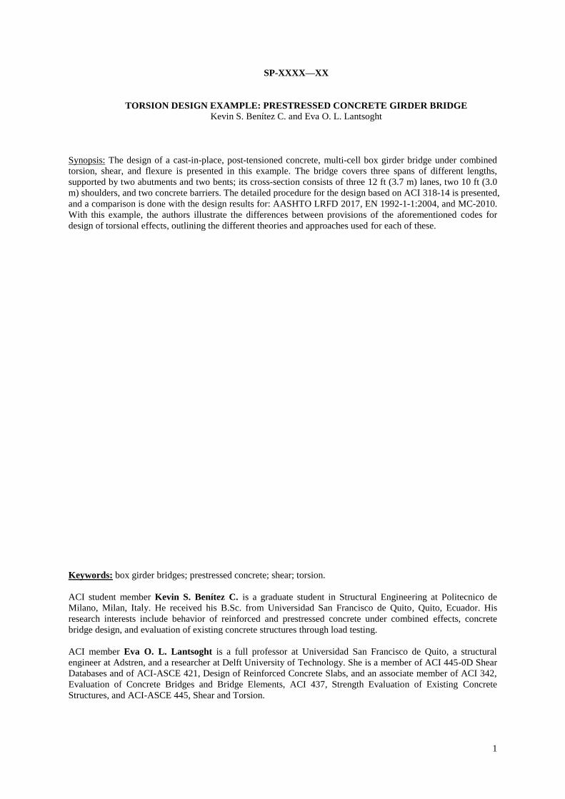
This example concerns the design for torsion of a three-span bridge, based on the geometry of an example from
the California Department of Transportation1. Figure 1 shows the elevation view of the bridge used for this
example. The total length of the three spans is 412’ (125.6 m): the first span is 126’ (38.4 m), the center span is
168’ (51.2 m), and the third span is 118’ (36.0 m).
Figure 1––Elevation view of the bridge.
Figure 2 presents the cross-section of the bridge. The total width of the bridge is 58’-10’’ (17.93 m). The bridge
carries three 12’ (3.7 m) traffic lanes, two 10’ (3.0 m) shoulders and two 1’-5’’ (0.45 m) concrete edge barriers.
Figure 2––Cross-section of the bridge.
The loads that act on the bridge include the self-weight, load of the asphalt concrete (A.C.) wearing
surface with a thickness of 3 in (75 mm), and the live load in accordance with AASHTO LRFD 20173 HL-
93 (design truck plus design lane load).
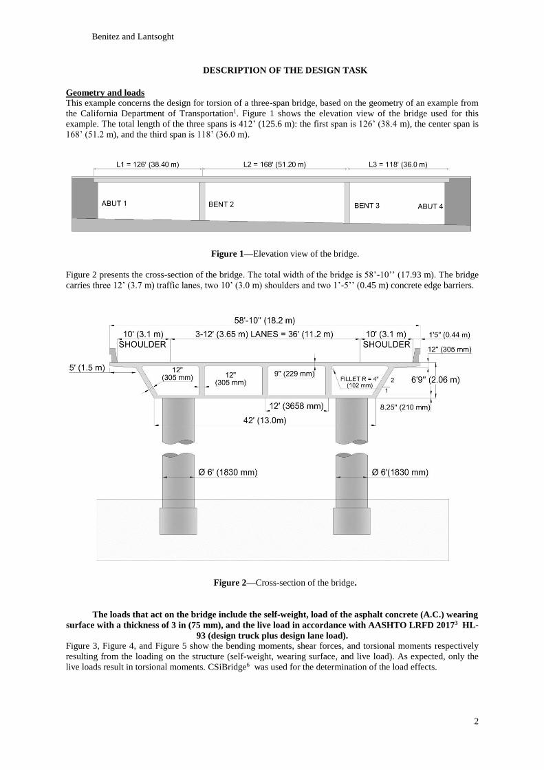
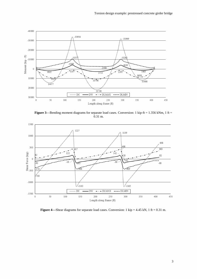
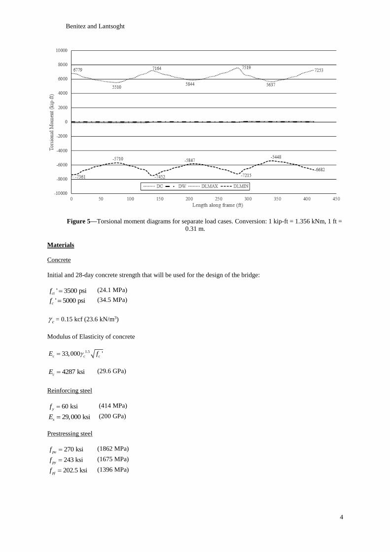
Figure 3, Figure 4, and Figure 5 show the bending moments, shear forces, and torsional moments respectively
resulting from the loading on the structure (self-weight, wearing surface, and live load). As expected, only the
live loads result in torsional moments. CSiBridge6 was used for the determination of the load effects.
Torsion design example: prestressed concrete girder bridge
3
Figure 3––Bending moment diagrams for separate load cases. Conversion: 1 kip-ft = 1.356 kNm, 1 ft =
0.31 m.
Figure 4––Shear diagrams for separate load cases. Conversion: 1 kip = 4.45 kN, 1 ft = 0.31 m.
Benitez and Lantsoght
4
Figure 5––Torsional moment diagrams for separate load cases. Conversion: 1 kip-ft = 1.356 kNm, 1 ft =
0.31 m.
Materials
Concrete
Initial and 28-day concrete strength that will be used for the design of the bridge:
' 3500 psicif (24.1 MPa)
' 5000 psicf (34.5 MPa)
c = 0.15 kcf (23.6 kN/m3)
Modulus of Elasticity of concrete
1.533,000 'c c cE f
4287 ksicE (29.6 GPa)
Reinforcing steel
60 ksiyf (414 MPa)
29,000 ksisE (200 GPa)
Prestressing steel
270 ksipuf (1862 MPa)
243 ksipyf (1675 MPa)
202.5 ksipjf (1396 MPa)
Torsion design example: prestressed concrete girder bridge
5
Statement of the design problem
The cross-section of this example bridge is subjected to a combination of flexure, shear, and torsion, hence the
design for each of these limit states will be developed. Special attention is given to the design for torsion. The
design of the prestressing steel is done in accordance with the requirements of AASHTO LRFD 20173. Then,
the design of all mild steel required to resist the effects of flexure, shear and torsion is done following the
requirements of: AASHTO LRFD 20173, ACI 318-142, EN 1992-1-1:20044, and MC-20105. The detailed
procedure for the design with ACI318-142 is presented. In practice, the design engineer would only use the
AASHTO LRFD 2017 provisions to determine the required reinforcement (or the relevant local code, if the
bridge is not to be built in North America), but this example serves for the comparison between the approaches
of the different codes. The design results following the other codes are included, so that a comparison between
the requirements and design results of the studied design codes is possible.
DESIGN PROCEDURE
Design of prestressing steel
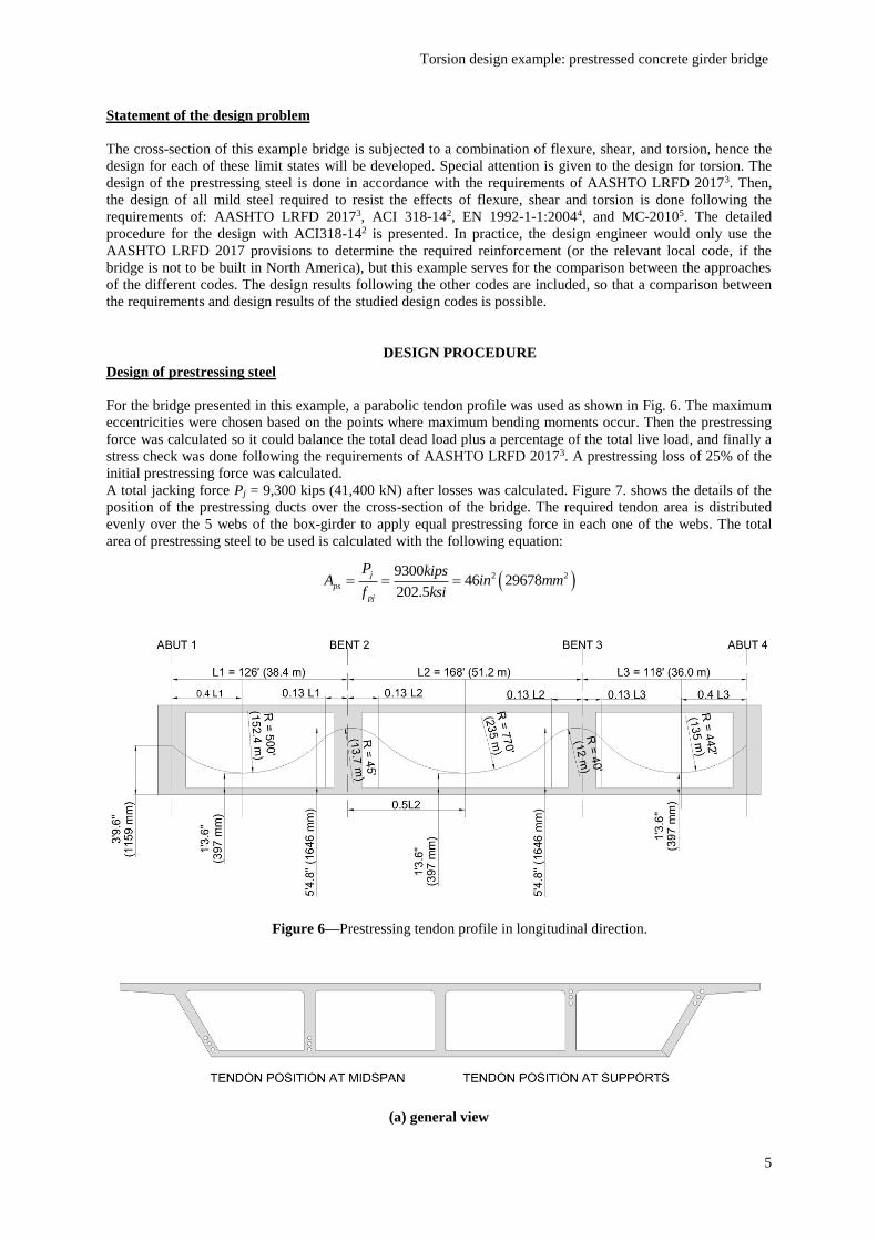
For the bridge presented in this example, a parabolic tendon profile was used as shown in Fig. 6. The maximum
eccentricities were chosen based on the points where maximum bending moments occur. Then the prestressing
force was calculated so it could balance the total dead load plus a percentage of the total live load, and finally a
stress check was done following the requirements of AASHTO LRFD 20173. A prestressing loss of 25% of the
initial prestressing force was calculated.
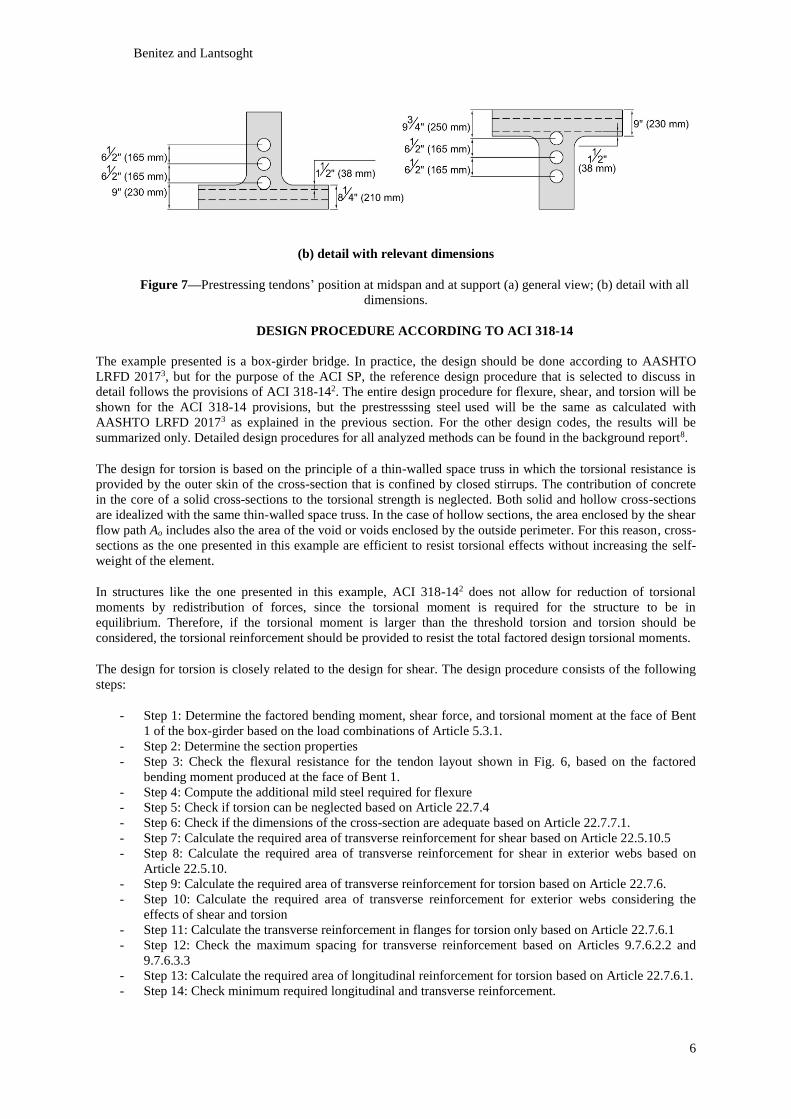
A total jacking force Pj = 9,300 kips (41,400 kN) after losses was calculated. Figure 7. shows the details of the
position of the prestressing ducts over the cross-section of the bridge. The required tendon area is distributed
evenly over the 5 webs of the box-girder to apply equal prestressing force in each one of the webs. The total
area of prestressing steel to be used is calculated with the following equation:
2 2930046 29678
202.5
j
ps
pj
P kipsA in mm
f ksi
Figure 6––Prestressing tendon profile in longitudinal direction.
(a) general view
Benitez and Lantsoght
6
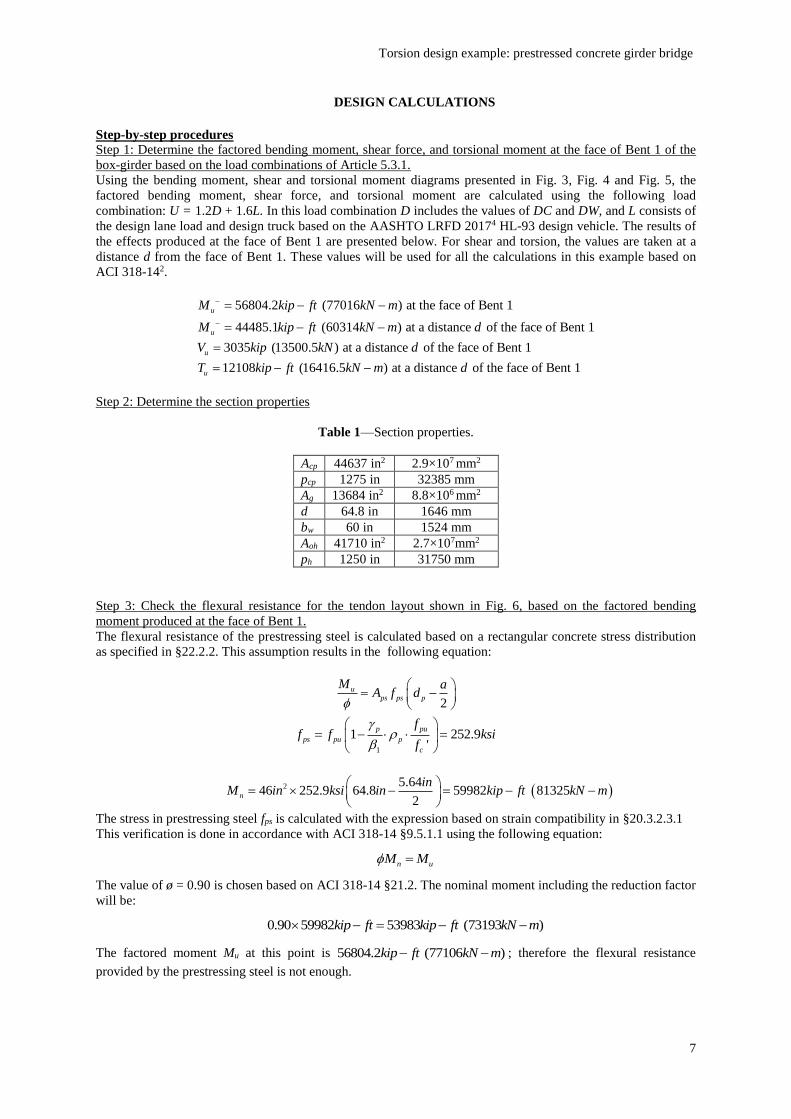
(b) detail with relevant dimensions
Figure 7––Prestressing tendons’ position at midspan and at support (a) general view; (b) detail with all
dimensions.
DESIGN PROCEDURE ACCORDING TO ACI 318-14
The example presented is a box-girder bridge. In practice, the design should be done according to AASHTO
LRFD 20173, but for the purpose of the ACI SP, the reference design procedure that is selected to discuss in
detail follows the provisions of ACI 318-142. The entire design procedure for flexure, shear, and torsion will be
shown for the ACI 318-14 provisions, but the prestresssing steel used will be the same as calculated with
AASHTO LRFD 20173 as explained in the previous section. For the other design codes, the results will be
summarized only. Detailed design procedures for all analyzed methods can be found in the background report8.
The design for torsion is based on the principle of a thin-walled space truss in which the torsional resistance is
provided by the outer skin of the cross-section that is confined by closed stirrups. The contribution of concrete
in the core of a solid cross-sections to the torsional strength is neglected. Both solid and hollow cross-sections
are idealized with the same thin-walled space truss. In the case of hollow sections, the area enclosed by the shear
flow path Ao includes also the area of the void or voids enclosed by the outside perimeter. For this reason, cross-
sections as the one presented in this example are efficient to resist torsional effects without increasing the self-
weight of the element.
In structures like the one presented in this example, ACI 318-142 does not allow for reduction of torsional
moments by redistribution of forces, since the torsional moment is required for the structure to be in
equilibrium. Therefore, if the torsional moment is larger than the threshold torsion and torsion should be
considered, the torsional reinforcement should be provided to resist the total factored design torsional moments.
The design for torsion is closely related to the design for shear. The design procedure consists of the following
steps:
- Step 1: Determine the factored bending moment, shear force, and torsional moment at the face of Bent
1 of the box-girder based on the load combinations of Article 5.3.1.
- Step 2: Determine the section properties
- Step 3: Check the flexural resistance for the tendon layout shown in Fig. 6, based on the factored
bending moment produced at the face of Bent 1.
- Step 4: Compute the additional mild steel required for flexure
- Step 5: Check if torsion can be neglected based on Article 22.7.4
- Step 6: Check if the dimensions of the cross-section are adequate based on Article 22.7.7.1.
- Step 7: Calculate the required area of transverse reinforcement for shear based on Article 22.5.10.5
- Step 8: Calculate the required area of transverse reinforcement for shear in exterior webs based on
Article 22.5.10.
- Step 9: Calculate the required area of transverse reinforcement for torsion based on Article 22.7.6.
- Step 10: Calculate the required area of transverse reinforcement for exterior webs considering the
effects of shear and torsion
- Step 11: Calculate the transverse reinforcement in flanges for torsion only based on Article 22.7.6.1
- Step 12: Check the maximum spacing for transverse reinforcement based on Articles 9.7.6.2.2 and
9.7.6.3.3
- Step 13: Calculate the required area of longitudinal reinforcement for torsion based on Article 22.7.6.1.
- Step 14: Check minimum required longitudinal and transverse reinforcement.
Torsion design example: prestressed concrete girder bridge
7
DESIGN CALCULATIONS
Step-by-step procedures
Step 1: Determine the factored bending moment, shear force, and torsional moment at the face of Bent 1 of the
box-girder based on the load combinations of Article 5.3.1.
Using the bending moment, shear and torsional moment diagrams presented in Fig. 3, Fig. 4 and Fig. 5, the
factored bending moment, shear force, and torsional moment are calculated using the following load
combination: U = 1.2D + 1.6L. In this load combination D includes the values of DC and DW, and L consists of
the design lane load and design truck based on the AASHTO LRFD 20174 HL-93 design vehicle. The results of
the effects produced at the face of Bent 1 are presented below. For shear and torsion, the values are taken at a
distance d from the face of Bent 1. These values will be used for all the calculations in this example based on
ACI 318-142.
56804.2 (77016 ) at the face of Bent 1
44485.1 (60314 ) at a distance of the face of Bent 1
3035 (13500.5 ) at a distance of the face of Bent 1
12108 (16416.
u
u
u
u
M kip ft kN m
M kip ft kN m d
V kip kN d
T kip ft
5 ) at a distance of the face of Bent 1kN m d
Step 2: Determine the section properties
Table 1––Section properties.
Acp 44637 in2 2.9×107 mm2
pcp 1275 in 32385 mm
Ag 13684 in2 8.8×106 mm2
d 64.8 in 1646 mm
bw 60 in 1524 mm
Aoh 41710 in2 2.7×107mm2
ph 1250 in 31750 mm
Step 3: Check the flexural resistance for the tendon layout shown in Fig. 6, based on the factored bending
moment produced at the face of Bent 1.
The flexural resistance of the prestressing steel is calculated based on a rectangular concrete stress distribution
as specified in §22.2.2. This assumption results in the following equation:
2
u
ps ps p
M aA f d
1
1 252.9'
p pu
ps pu p
c
ff f ksi
f
2 5.6446 252.9 64.8 59982 81325
2n
inM in ksi in kip ft kN m
The stress in prestressing steel fps is calculated with the expression based on strain compatibility in §20.3.2.3.1
This verification is done in accordance with ACI 318-14 §9.5.1.1 using the following equation:
n uM M
The value of ø = 0.90 is chosen based on ACI 318-14 §21.2. The nominal moment including the reduction factor
will be:
0.90 59982 53983 (73193 )kip ft kip ft kN m
The factored moment Mu at this point is 56804.2 (77106 )kip ft kN m ; therefore the flexural resistance
provided by the prestressing steel is not enough.
Benitez and Lantsoght
8
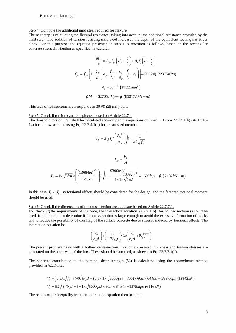
Step 4: Compute the additional mild steel required for flexure
The next step is calculating the flexural resistance, taking into account the additional resistance provided by the
mild steel. The addition of tension-resisting mild steel increases the depth of the equivalent rectangular stress
block. For this purpose, the equation presented in step 1 is rewritten as follows, based on the rectangular
concrete stress distribution as specified in §22.2.2.
2 2
u
ps ps p s y
M a aA f d A f d
1
1 250 (1723.7 )' '
p pu ys
ps pu p l
c p c
f fdf f ksi MPa
f d f
2 230 19355sA in mm
62705.4 (85017.1 )nM kip ft kN m
This area of reinforcement corresponds to 39 #8 (25 mm) bars.
Step 5: Check if torsion can be neglected based on Article 22.7.4
The threshold torsion (Tth) shall be calculated according to the equations outlined in Table 22.7.4.1(b) (ACI 318-
14) for hollow sections using Eq. 22.7.4.1(b) for prestressed members:
2
' 14 '
g pc
th c
cp c
A fT f
p f
j
pc
Pf
A
22
2930013684 133921 5 1 1609 2182
1275 4 1 5th
ksiin inT ksi kip ft kN min ksi
In this case th uT T , so torsional effects should be considered for the design, and the factored torsional moment
should be used.
Step 6: Check if the dimensions of the cross-section are adequate based on Article 22.7.7.1.
For checking the requirements of the code, the interaction equation 22.7.7.1(b) (for hollow sections) should be
used. It is important to determine if the cross-section is large enough to avoid the excessive formation of cracks
and to reduce the possibility of crushing of the surface concrete due to stresses induced by torsional effects. The
interaction equation is:
8 '1.7
u u c
c
w oh w
V T Vf
b d A t b d
The present problem deals with a hollow cross-section. In such a cross-section, shear and torsion stresses are
generated on the outer wall of the box. These should be summed, as shown in Eq. 22.7.7.1(b).
The concrete contribution to the nominal shear strength (Vc) is calculated using the approximate method
provided in §22.5.8.2:
0.6 ' 700 (0.6 1 5000 700) 60 64.8 2887 (12842 )
5 ' 5 1 5000 60 64.8 1375 (6116 )
c c w
c c w
V f b d psi in in kips kN
V f b d psi in in kips kN
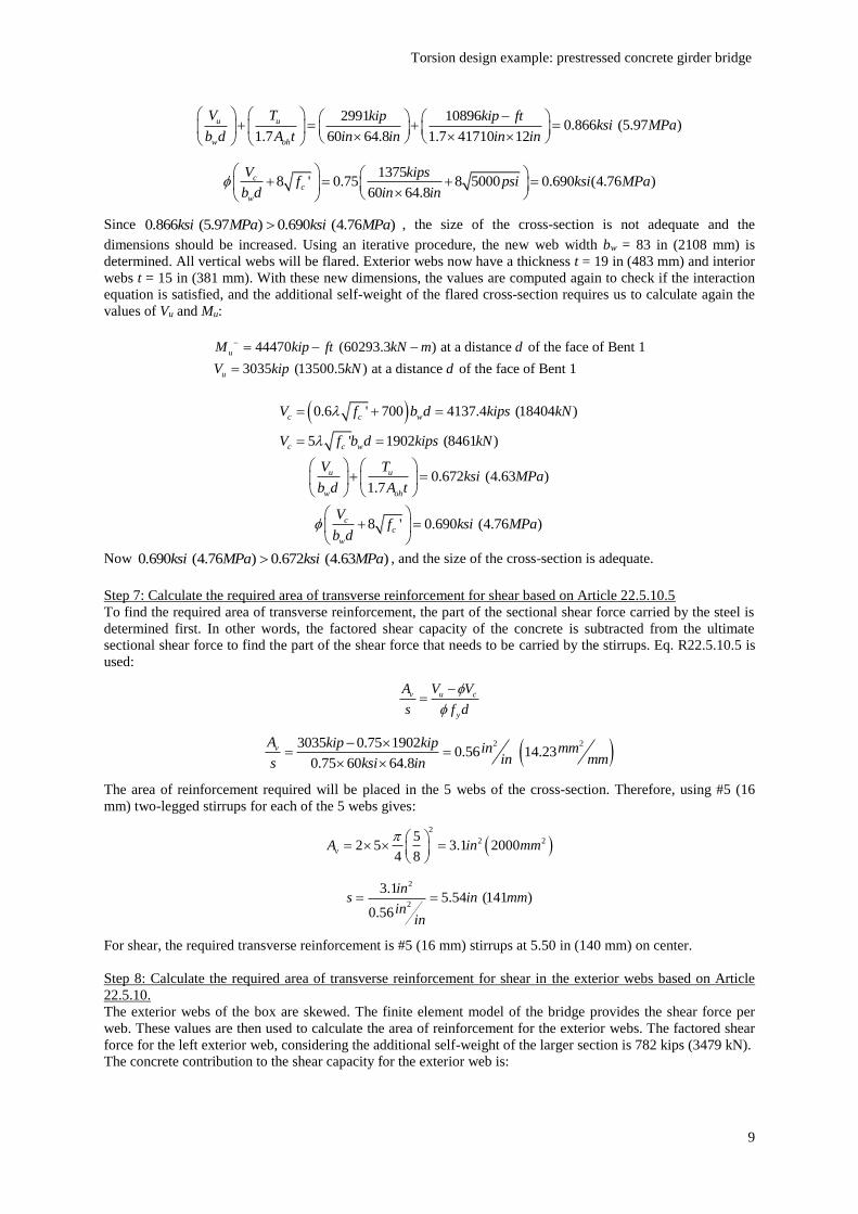
The results of the inequality from the interaction equation then become:
Torsion design example: prestressed concrete girder bridge
9
2991 108960.866 (5.97 )
1.7 60 64.8 1.7 41710 12
u u
w oh
V T kip kip ftksi MPa
b d A t in in in in
13758 ' 0.75 8 5000 0.690 (4.76 )
60 64.8
cc
w
V kipsf psi ksi MPa
b d in in
Since 0.866 (5.97 ) 0.690 (4.76 )ksi MPa ksi MPa , the size of the cross-section is not adequate and the
dimensions should be increased. Using an iterative procedure, the new web width bw = 83 in (2108 mm) is
determined. All vertical webs will be flared. Exterior webs now have a thickness t = 19 in (483 mm) and interior
webs t = 15 in (381 mm). With these new dimensions, the values are computed again to check if the interaction
equation is satisfied, and the additional self-weight of the flared cross-section requires us to calculate again the
values of Vu and Mu:
44470 (60293.3 ) at a distance of the face of Bent 1
3035 (13500.5 ) at a distance of the face of Bent 1
u
u
M kip ft kN m d
V kip kN d
0.6 ' 700 4137.4 (18404 )
5 ' 1902 (8461 )
c c w
c c w
V f b d kips kN
V f b d kips kN
0.672 (4.63 )1.7
u u
w oh
V Tksi MPa
b d A t
8 ' 0.690 (4.76 )c
c
w
Vf ksi MPa
b d
Now 0.690 (4.76 ) 0.672 (4.63 )ksi MPa ksi MPa , and the size of the cross-section is adequate.
Step 7: Calculate the required area of transverse reinforcement for shear based on Article 22.5.10.5
To find the required area of transverse reinforcement, the part of the sectional shear force carried by the steel is
determined first. In other words, the factored shear capacity of the concrete is subtracted from the ultimate
sectional shear force to find the part of the shear force that needs to be carried by the stirrups. Eq. R22.5.10.5 is
used:
v u c
y
A V V
s f d
2 23035 0.75 19020.56 14.23
0.75 60 64.8
vA kip kip in mmin mms ksi in
The area of reinforcement required will be placed in the 5 webs of the cross-section. Therefore, using #5 (16
mm) two-legged stirrups for each of the 5 webs gives:
2
2 252 5 3.1 2000
4 8vA in mm
2
2
3.15.54 (141 )
0.56
ins in mm
inin
For shear, the required transverse reinforcement is #5 (16 mm) stirrups at 5.50 in (140 mm) on center.
Step 8: Calculate the required area of transverse reinforcement for shear in the exterior webs based on Article
22.5.10.
The exterior webs of the box are skewed. The finite element model of the bridge provides the shear force per
web. These values are then used to calculate the area of reinforcement for the exterior webs. The factored shear
force for the left exterior web, considering the additional self-weight of the larger section is 782 kips (3479 kN).
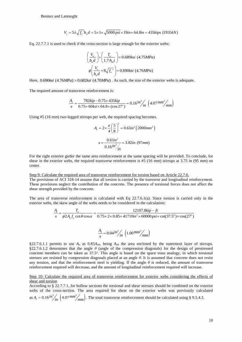
The concrete contribution to the shear capacity for the exterior web is:
Benitez and Lantsoght
10
5 ' 5 1 5000 19 64.8 435 (1935 )c c wV f b d psi in in kips kN
Eq. 22.7.7.1 is used to check if the cross-section is large enough for the exterior webs:
0.689 (4.75 )1.7
u u
w oh
V Tksi MPa
b d A t
8 ' 0.690 (4.76 )c
c
w
Vf ksi MPa
b d
Here, 0.690 (4.76 ) 0.682 (4.70 )ksi MPa ksi MPa . As such, the size of the exterior webs is adequate.
The required amount of transverse reinforcement is:
2 2782 0.75 4350.16 4.07
0.75 60 64.8 (cos 27 )
v
o
A kip kip in mmin mms ksi
Using #5 (16 mm) two-legged stirrups per web, the required spacing becomes.
2
2 252 0.61 2000
4 8vA in mm
2
2
0.613.82 (97 )
0.16
ins in mm
inin
For the right exterior girder the same area reinforcement at the same spacing will be provided. To conclude, for
shear in the exterior webs, the required transverse reinforcement is #5 (16 mm) stirrups at 3.75 in (95 mm) on
center.
Step 9: Calculate the required area of transverse reinforcement for torsion based on Article 22.7.6.
The provisions of ACI 318-14 assume that all torsion is carried by the tranverse and longitudinal reinforcement.
These provisions neglect the contribution of the concrete. The presence of torsional forces does not affect the
shear strength provided by the concrete.
The area of transverse reinforcement is calculated with Eq 22.7.6.1(a). Since torsion is carried only in the
exterior webs, the skew angle of the webs needs to be considered in the calculation:
2
12107.8
2 cot cos 0.75 2 0.85 41710 60000 cot(37.5 ) cos(27 )
t u
o o
o y
A T kip ft
s A f in psi
2 2
0.04 1.00tA in mmin mms
§22.7.6.1.1 permits to use Ao as 0.85Aoh, being Aoh the area enclosed by the outermost layer of stirrups.
§22.7.6.1.2 determines that the angle θ (angle of the compression diagonals) for the design of prestressed
concrete members can be taken as 37.5o. This angle is based on the space truss analogy, in which torsional
stresses are resisted by compression diagonals placed at an angle θ. It is assumed that concrete does not resist
any tension, and that the reinforcement steel is yielding. If the angle θ is reduced, the amount of transverse
reinforcement required will decrease, and the amount of longitudinal reinforcement required will increase.
Step 10: Calculate the required area of transverse reinforcement for exterior webs considering the effects of
shear and torsion
According to § 22.7.7.1, for hollow sections the torsional and shear stresses should be combined on the exterior
webs of the cross-section. The area required for shear on the exterior webs was previously calculated
as 2 2
0.16 4.07vin mmA
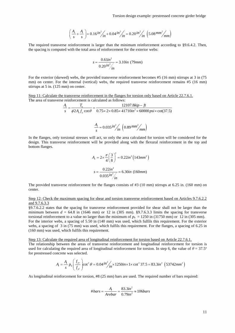
in mm . The total transverse reinforcement should be calculated using § 9.5.4.3.
Torsion design example: prestressed concrete girder bridge
11
2 2 2 2
0.16 0.04 0.20 5.08v tA A in in in mmin in in mms s
The required transverse reinforcement is larger than the minimum reinforcement according to §9.6.4.2. Then,
the spacing is computed with the total area of reinforcement for the exterior webs:
2
2
0.613.10 (79 )
0.20
ins in mm
inin
For the exterior (skewed) webs, the provided transverse reinforcement becomes #5 (16 mm) stirrups at 3 in (75
mm) on center. For the internal (vertical) webs, the required transverse reinforcement remains #5 (16 mm)
stirrups at 5 in. (125 mm) on center.
Step 11: Calculate the transverse reinforcement in the flanges for torsion only based on Article 22.7.6.1.
The area of transverse reinforcement is calculated as follows:
2
12107.8
2 cot 0.75 2 0.85 41710 60000 cot(37.5)
t u
o y
A T kip ft
s A f in psi
2 2
0.035 0.89tA in mmin mms
In the flanges, only torsional stresses will act, so only the area calculated for torsion will be considered for the
design. This transverse reinforcement will be provided along with the flexural reinforcement in the top and
bottom flanges.
2
2 232 0.22 143
4 8vA in mm
2
2
0.226.30 (160 )
0.035
ins in mm
inin
The provided transverse reinforcement for the flanges consists of #3 (10 mm) stirrups at 6.25 in. (160 mm) on
center.
Step 12: Check the maximum spacing for shear and torsion transverse reinforcement based on Articles 9.7.6.2.2
and 9.7.6.3.3
§9.7.6.2.2 states that the spacing for transverse reinforcement provided for shear shall not be larger than the
minimum between d = 64.8 in (1646 mm) or 12 in (305 mm). §9.7.6.3.3 limits the spacing for transverse
torsional reinforcement to a value no larger than the minimum of ph = 1250 in (31750 mm) or 12 in (305 mm).
For the interior webs, a spacing of 5.50 in (140 mm) was used, which fulfils this requirement. For the exterior
webs, a spacing of 3 in (75 mm) was used, which fulfils this requirement. For the flanges, a spacing of 6.25 in
(160 mm) was used, which fulfils this requirement.
Step 13: Calculate the required area of longitudinal reinforcement for torsion based on Article 22.7.6.1.
The relationship between the areas of transverse reinforcement and longitudinal reinforcement for torsion is
used for calculating the required area of longitudinal reinforcement for torsion. In step 6, the value of θ = 37.5o
for prestressed concrete was selected.
2
2 2 2 2cot 0.04 1250 1 cot 37.5 83.3 53742yvt
l h
yl
fA inA p in in mmins f
As longitudinal reinforcement for torsion, #8 (25 mm) bars are used. The required number of bars required:
2
2
83.3# 106
0.79
lA inbars bars
Arebar in
Benitez and Lantsoght
12
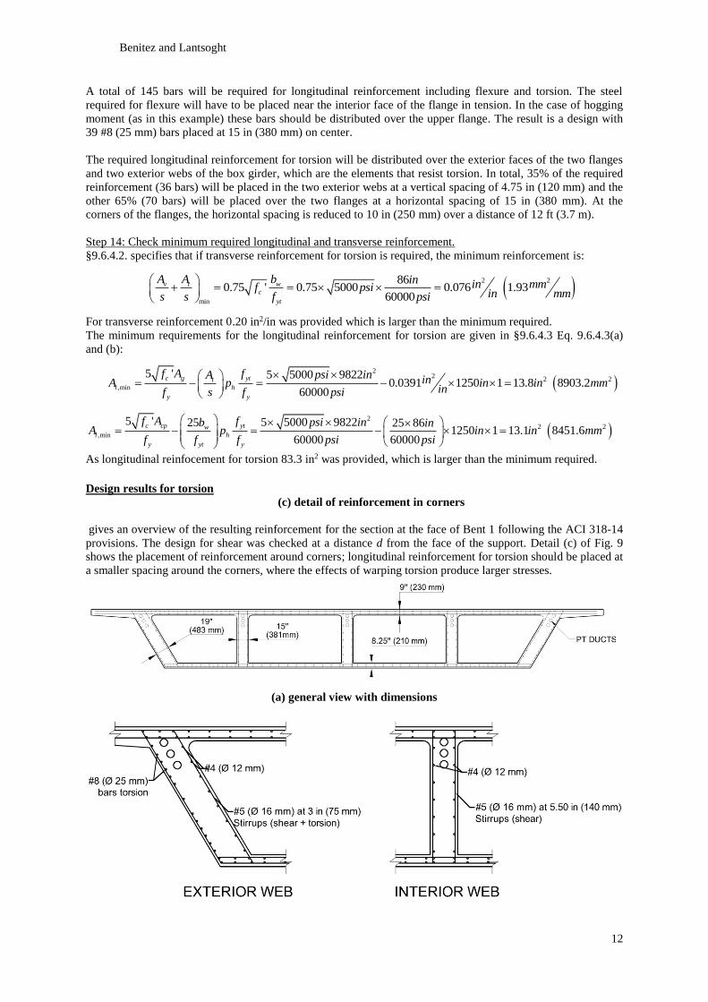
A total of 145 bars will be required for longitudinal reinforcement including flexure and torsion. The steel
required for flexure will have to be placed near the interior face of the flange in tension. In the case of hogging
moment (as in this example) these bars should be distributed over the upper flange. The result is a design with
39 #8 (25 mm) bars placed at 15 in (380 mm) on center.
The required longitudinal reinforcement for torsion will be distributed over the exterior faces of the two flanges
and two exterior webs of the box girder, which are the elements that resist torsion. In total, 35% of the required
reinforcement (36 bars) will be placed in the two exterior webs at a vertical spacing of 4.75 in (120 mm) and the
other 65% (70 bars) will be placed over the two flanges at a horizontal spacing of 15 in (380 mm). At the
corners of the flanges, the horizontal spacing is reduced to 10 in (250 mm) over a distance of 12 ft (3.7 m).
Step 14: Check minimum required longitudinal and transverse reinforcement.
§9.6.4.2. specifies that if transverse reinforcement for torsion is required, the minimum reinforcement is:
2 2
min
860.75 ' 0.75 5000 0.076 1.93
60000
v t w
c
yt
A A b in in mmf psiin mms s f psi
For transverse reinforcement 0.20 in2/in was provided which is larger than the minimum required.
The minimum requirements for the longitudinal reinforcement for torsion are given in §9.6.4.3 Eq. 9.6.4.3(a)
and (b):
2
22 2
,min
5 ' 5 5000 98220.0391 1250 1 13.8 8903.2
60000
c g ytt
l h
y y
f A f psi inA inA p in in mminf s f psi
2
2 2
,min
5 ' 5 5000 982225 25 861250 1 13.1 8451.6
60000 60000
c cp ytw
l h
y yt y
f A f psi inb inA p in in mm
f f f psi psi
As longitudinal reinfocement for torsion 83.3 in2 was provided, which is larger than the minimum required.
Design results for torsion
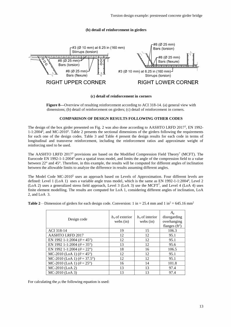
(c) detail of reinforcement in corners
gives an overview of the resulting reinforcement for the section at the face of Bent 1 following the ACI 318-14
provisions. The design for shear was checked at a distance d from the face of the support. Detail (c) of Fig. 9
shows the placement of reinforcement around corners; longitudinal reinforcement for torsion should be placed at
a smaller spacing around the corners, where the effects of warping torsion produce larger stresses.
(a) general view with dimensions
Torsion design example: prestressed concrete girder bridge
13
(b) detail of reinforcement in girders
(c) detail of reinforcement in corners
Figure 8––Overview of resulting reinforcement according to ACI 318-14. (a) general view with
dimensions; (b) detail of reinforcement on girders; (c) detail of reinforcement in corners.
COMPARISON OF DESIGN RESULTS FOLLOWING OTHER CODES
The design of the box girder presented on Fig. 2 was also done according to AASHTO LRFD 20173, EN 1992-
1-1:20044, and MC-20105. Table 2 presents the sectional dimensions of the girders following the requirements
for each one of the design codes. Table 3 and Table 4 present the design results for each code in terms of
longitudinal and transverse reinforcement, including the reinforcement ratios and approximate weight of
reinforcing steel to be used.
The AASHTO LRFD 20173 provisions are based on the Modified Compression Field Theory7 (MCFT). The
Eurocode EN 1992-1-1:20044 uses a spatial truss model, and limits the angle of the compression field to a value
between 22° and 45°. Therefore, in this example, the results will be computed for different angles of inclination
between the allowable limits to analyze the difference in results assuming different angles.
The Model Code MC-20105 uses an approach based on Levels of Approximation. Four different levels are
defined: Level 1 (LoA 1) uses a variable angle truss model, which is the same as EN 1992-1-1:20044, Level 2
(LoA 2) uses a generalized stress field approach, Level 3 (LoA 3) use the MCFT7, and Level 4 (LoA 4) uses
finite element modelling. The results are computed for LoA 1, considering different angles of inclination, LoA
2, and LoA 3.
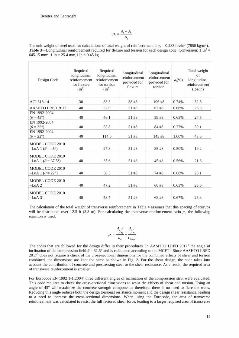
Table 2––Dimension of girders for each design code. Conversion: 1 in = 25.4 mm and 1 in2 = 645.16 mm2
Design code bw of exterior
webs (in)
bw of interior
webs (in)
Ag
disregarding
overhanging
flanges (ft2)
ACI 318-14 19 15 106.3
AASHTO LRFD 2017 12 12 95.1
EN 1992 1-1:2004 (θ = 45°) 12 12 95.1
EN 1992 1-1:2004 (θ = 35°) 13 12 95.6
EN 1992 1-1:2004 (θ = 22°) 18 16 106.5
MC-2010 (LoA 1) (θ = 45°) 12 12 95.1
MC-2010 (LoA 1) (θ = 37.5°) 12 12 95.1
MC-2010 (LoA 1) (θ = 25°) 16 14 101.8
MC-2010 (LoA 2) 13 13 97.4
MC-2010 (LoA 3) 13 13 97.4
For calculating the ρl the following equation is used:
Benitez and Lantsoght
14
l s
l
g
A A
A
The unit weight of steel used for calculations of total weight of reinforcement is γs = 0.283 lbs/in3 (7850 kg/m3).
Table 3––Longitudinal reinforcement required for flexure and torsion for each design code. Conversion: 1 in2 =
645.15 mm2, 1 in = 25.4 mm,1 lb = 0.45 kg.
Design Code
Required
longitudinal
reinforcement
for flexure
(in2)
Required
longitudinal
reinforcement
for torsion
(in2)
Longitudinal
reinforcement
provided for
flexure
Longitudinal
reinforcement
provided for
torsion
ρl(%)
Total weight
of
longitudinal
reinforcement
(lbs/in)
ACI 318-14 30 83.3 38 #8 106 #8 0.74% 32.3
AASHTO LRFD 2017 40 52.0 51 #8 67 #8 0.68% 26.3
EN 1992-2004
(θ = 45°) 40 46.1 51 #8 59 #8 0.63% 24.5
EN 1992-2004
(θ = 35°) 40 65.8 51 #8 84 #8 0.77% 30.1
EN 1992-2004
(θ = 22°) 40 114.0 51 #8 145 #8 1.00% 43.6
MODEL CODE 2010
–LoA 1 (θ = 45°) 40 27.3 51 #8 35 #8 0.50% 19.2
MODEL CODE 2010
–LoA 1 (θ = 37.5°) 40 35.6 51 #8 45 #8 0.56% 21.6
MODEL CODE 2010
–LoA 1 (θ = 22°) 40 58.5 51 #8 74 #8 0.68% 28.1
MODEL CODE 2010
–LoA 2 40 47.2 51 #8 60 #8 0.63% 25.0
MODEL CODE 2010
–LoA 3 40 53.7 51 #8 68 #8 0.67% 26.8
The calculation of the total weight of transverse reinforcement in Table 4 assumes that this spacing of stirrups
will be distributed over 12.5 ft (3.8 m). For calculating the transverse reinforcement ratio ρt, the following
equation is used:
v t
t
w flange
A As s
b t
The codes that are followed for the design differ in their procedures. In AASHTO LRFD 20173 the angle of
inclination of the compression field θ = 31.5° and is calculated according to the MCFT7. Since AASHTO LRFD
20173 does not require a check of the cross-sectional dimensions for the combined effects of shear and torsion
combined, the dimensions are kept the same as shown in Fig. 2. For the shear design, the code takes into
account the contribution of concrete and prestressing steel to the shear resistance. As a result, the required area
of transverse reinforcement is smaller.
For Eurocode EN 1992 1-1:20044 three different angles of inclination of the compression strut were evaluated.
This code requires to check the cross-sectional dimensions to resist the effects of shear and torsion. Using an
angle of 45° will maximize the concrete strength components; therefore, there is no need to flare the webs.
Reducing this angle reduces both the design torsional resistance moment and the design shear resistance, leading
to a need to increase the cross-sectional dimensions. When using the Eurocode, the area of transverse
reinforcement was calculated to resist the full factored shear force, leading to a larger required area of transverse
Torsion design example: prestressed concrete girder bridge
15
reinforcement. If the angle θ decreases, the required area of transverse reinforcement for shear and torsion also
decreases, but the area of longitudinal reinforcement for torsion increases.
In the Model Code MC-20105 Level of Approximation approach, the time and effort devoted to calculations
increases for increasing Levels of Approximation. Level 1 is based on a variable angle truss model, so in this
case the same results are found as for EN 1992 1-1:20044 when varying the angles of inclination of the
compression field. Level 2 is based on a generalized stress field, and this approach determined that θ = 30°.
Since here the concrete contribution to shear resistance is not taken into account, this angle of inclination of the
compression field will require to flare all interior webs. A balanced quantity of steel and a increase in gross area
of concrete of just 2% is required. Level 3 is based on the MCFT7 and it resulted on an angle θ = 27°, and this
approach contains the most time and effort-consuming method. Using this method also results in a balanced
quantity of steel and an increase in gross area of concrete of 2%, similar to the results with Level 2. In this
example, Level 2 and Level 3 have similar results of cross-sectional area of concrete and quantity of steel, so for
design it could be a good option to either use the generalized stress field based LoA 2 or the MCFT-based7 LoA
3.
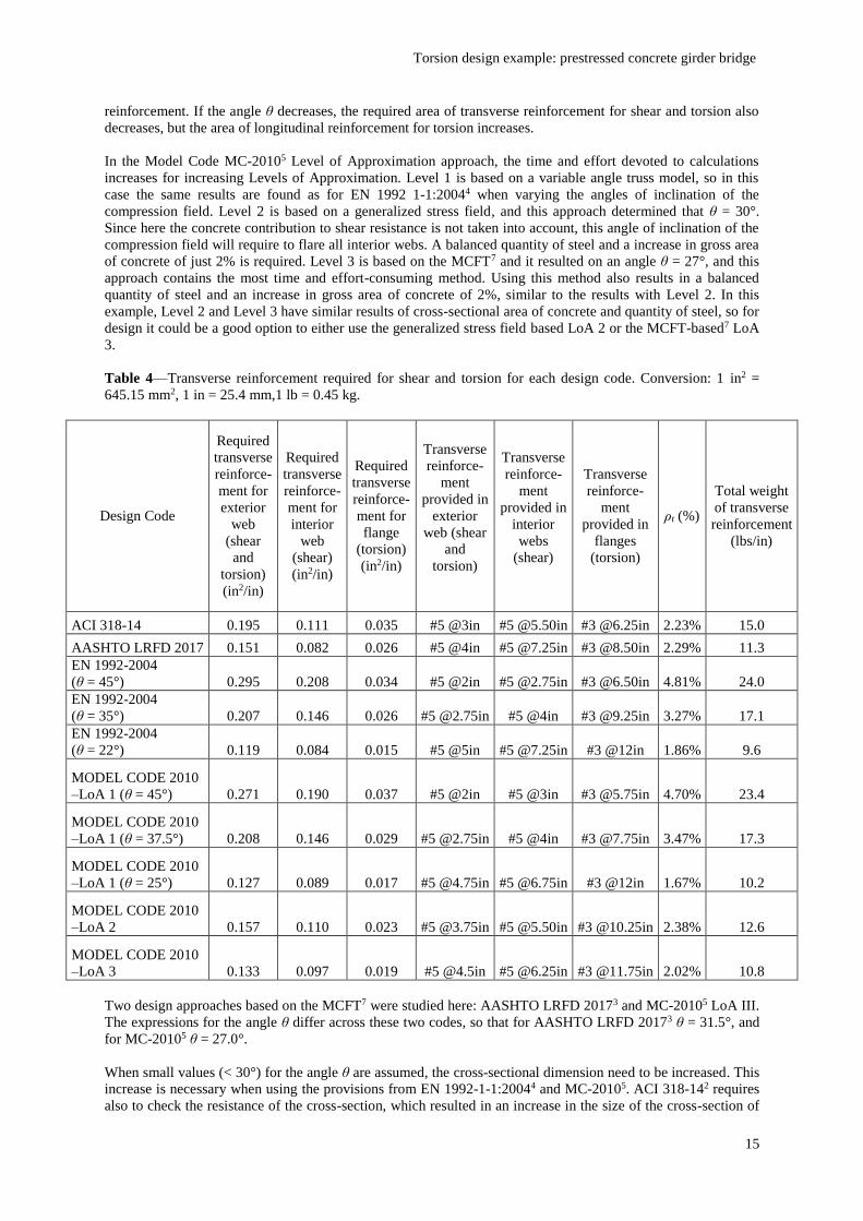
Table 4––Transverse reinforcement required for shear and torsion for each design code. Conversion: 1 in2 =
645.15 mm2, 1 in = 25.4 mm,1 lb = 0.45 kg.
Design Code
Required
transverse
reinforce-
ment for
exterior
web
(shear
and
torsion)
(in2/in)
Required
transverse
reinforce-
ment for
interior
web
(shear)
(in2/in)
Required
transverse
reinforce-
ment for
flange
(torsion)
(in2/in)
Transverse
reinforce-
ment
provided in
exterior
web (shear
and
torsion)
Transverse
reinforce-
ment
provided in
interior
webs
(shear)
Transverse
reinforce-
ment
provided in
flanges
(torsion)
ρt (%)
Total weight
of transverse
reinforcement
(lbs/in)
ACI 318-14 0.195 0.111 0.035 #5 @3in #5 @5.50in #3 @6.25in 2.23% 15.0
AASHTO LRFD 2017 0.151 0.082 0.026 #5 @4in #5 @7.25in #3 @8.50in 2.29% 11.3
EN 1992-2004
(θ = 45°) 0.295 0.208 0.034 #5 @2in #5 @2.75in #3 @6.50in 4.81% 24.0
EN 1992-2004
(θ = 35°) 0.207 0.146 0.026 #5 @2.75in #5 @4in #3 @9.25in 3.27% 17.1
EN 1992-2004
(θ = 22°) 0.119 0.084 0.015 #5 @5in #5 @7.25in #3 @12in 1.86% 9.6
MODEL CODE 2010
–LoA 1 (θ = 45°) 0.271 0.190 0.037 #5 @2in #5 @3in #3 @5.75in 4.70% 23.4
MODEL CODE 2010
–LoA 1 (θ = 37.5°) 0.208 0.146 0.029 #5 @2.75in #5 @4in #3 @7.75in 3.47% 17.3
MODEL CODE 2010
–LoA 1 (θ = 25°) 0.127 0.089 0.017 #5 @4.75in #5 @6.75in #3 @12in 1.67% 10.2
MODEL CODE 2010
–LoA 2 0.157 0.110 0.023 #5 @3.75in #5 @5.50in #3 @10.25in 2.38% 12.6
MODEL CODE 2010
–LoA 3 0.133 0.097 0.019 #5 @4.5in #5 @6.25in #3 @11.75in 2.02% 10.8
Two design approaches based on the MCFT7 were studied here: AASHTO LRFD 20173 and MC-20105 LoA III.
The expressions for the angle θ differ across these two codes, so that for AASHTO LRFD 20173 θ = 31.5°, and
for MC-20105 θ = 27.0°.
When small values (< 30°) for the angle θ are assumed, the cross-sectional dimension need to be increased. This
increase is necessary when using the provisions from EN 1992-1-1:20044 and MC-20105. ACI 318-142 requires
also to check the resistance of the cross-section, which resulted in an increase in the size of the cross-section of
Benitez and Lantsoght
16
almost 12%. AASHTO LRFD 20173 does not require any check of the cross-section; only the combination of
effects produced by shear and torsion has to be considered in the calculation of the longitudinal strain. So, using
a lower angle of the compression field such as the minimum angle provided by EN 1992-1-1:20044 or MC-
20105 results in an uneconomical solution in terms of required longitudinal reinforcement and required gross
area of concrete.
For an angle of the compression strut of θ = 45°, large amounts of transverse reinforcement are found, and small
amounts of longitudinal reinforcement result. On the other hand, for a smaller angle of the compression strut θ
taken as 22° and 25°, the opposite results: small amounts of transverse reinforcement and large amounts of
longitudinal reinforcement are found. This conclusion can also be drawn based on the resulting weight of
reinforcement from Table 2 and Table 3. As such, for design it is recommended to balance the required areas of
transverse and longitudinal reinforcement by choosing a mean angle between the allowable limits when using
the provisions from EN 1992-1-1:20044 and MC-20105 Level of Approximation I. The recommendation from
ACI 318-142 to use an angle θ = 37.5o is in line with these observations.
Using the procedures of AASHTO LRFD 20173 and MC-20105 LoA 3 will require more computational time
and effort, since both use a MCFT7-based approach, but they will lead to a more economical and balanced
design solution. In terms of resulting quantity of steel, both methods lead to a similar provided total area (sum of
longitudinal and transverse steel) of steel reinforcement. There is some difference in the cross-sectional area,
since the MC-20105 design solution requires an increase of 2% of Ag. resulting in an increase of 2.30 ft2 (213677
mm2) of concrete. As such, the design solution using AASHTO LRFD 20173 is the most economical design.
SUMMARY AND CONCLUSIONS
In this example, the detailed design of a cast-in-place, post-tensioned concrete, multi-cell box girder bridge
under a combination of the effects of flexure, shear and torsion is presented. The starting point for the geometry
was taken from a design example of the California Department of Transportation1. Then, using a linear finite
elements software package for bridge design (CSI Bridge)6, the bending moments, shear, and torsional moments
where obtained. The design of the prestressing steel was done following AASHTO LRFD 20173 guidelines
using a parabolic tendon profile. Consequently, the example includes the detailed procedure for the design of
flexure, shear, and torsion following the requirements of ACI 318-142. Finally the design results of AASHTO
LRFD 20173, EN 1992-1-1:20044 and MC-20105 are presented, so a comparison between the design results is
made.
Each of the analyzed design codes has its own design metodology and principles. ACI 318-142 uses a space
truss analogy and a thin-walled tube analogy, AASHTO LRFD 20173 uses a simplification of the Modified
Compression Field Theory7, EN 1992-1-1:20044 uses a variable angle truss model based on an equivalent thin-
walled tube, and MC-20105 uses different Levels of Approximation. For MC-2010 the theories used are a
variable angle truss model, generalized stress field, or a simplification of the MCFT7, depending on the Level of
Approximation.
ACI 318-142 results in large amounts of required steel and concrete, as its provisions are more conservative in
some aspects. When using a variable angle truss model as in EN 1992-1-1:20044 and MC-20105 LoA 1, the
presented case study shows that it is recommended to use a mean angle between the minimum and maximum
allowable limits, as this approach will result in a more balanced design solution of steel and concrete. Finally
using more time and effort-consuming design solutions as for example MC-20105 LoA 2 and 3 or AASHTO
LRFD 20173 will lead to the most economical and balanced of all solutions obtained.
LIST OF NOTATIONS
a = depth of equivalent rectangular stress block,
Acp = area enclosed by the outside perimeter of concrete cross-section,
Ag = gross area of concrete cross-section,
Al = total area of longitudinal reinforcement to resist torsion,
Al,min = minimum area of longitudinal reinforcement to resist torsion,
Aoh = area enclosed by centerline of the outermost closed transverse torsional reinforcement,
Ao = gross area enclosed by torsional shear flow path,
Aps = area of prestressed longitudinal tension reinforcement,
As = area of nonprestressed longitudinal tension reinforcement,
At = area of a closed stirrup, hoop or tie resisting torsion,
Av = area of shear reinforcement,
Torsion design example: prestressed concrete girder bridge
17
bw = web width,
d = distance from extreme compression fiber to centroid of longitudinal tension reinforcement,
dp = distance from extreme compression fiber to centroid of prestressing reinforcement,
D = effect of service dead load,
DC = weight of supported structure,
DW = weight of wearing surface (superimposed dead load),
Ec = modulus of elasticity of concrete,
Es = modulus of elasticity of steel,
f’c = specified compressive strength of concrete,
f’ci = specified compressive strength of concrete at time of initial prestress,
fpc = compressive stress in concrete, at centroid of cross-section resisting externally applied loads,
fpj = prestressing steel stress at effective jacking force,
fps = stress in prestressing reinforcement at nominal flexural strength,
fpu = specified tensile strength of prestressing reinforcement,
fpy = specified yield strength of prestressing reinforcement,
fy = specified yield strength for nonprestressed reinforcement,
fyv = specified yield strength of transverse shear reinforcement,
fyt = specified yield strength of transverse torsion reinforcement,
L = effect of service live load,
LL = vehicular live load,
Mn = nominal flexural strength at section,
Mu = factored moment at section,
pcp = outside perimeter of concrete cross-section,
ph = perimeter of centerline of outermost closed transverse torsional reinforcement,
Pj = effective jacking force (after losses),
s = center-to-center spacing of longitudinal and transverse reinforcement,
t = wall thickness of hollow section,
Tth = threshold torsional moment,
Tu = factored torsional moment,
U = strength of a member or cross-section required to resist factored loads,
Vc = nominal shear strength provided by concrete,
Vu = factored shear force at section,
α = angle defining the orientation of reinforcement for skewed girders,
εs = tensile strain in extreme layer of longitudinal tension reinforcement at nominal strength,
θ = angle between axis of compression field and tension chord of a member,
λ = modification factor for lightweight concrete,
ρl = ratio of area of longitudinal reinforcement,
ρt = ratio of area of transverse reinforcement,
γc
γs
=
=
unit weight of concrete,
unit weight of steel,
ϕ = strength reduction factor,
REFERENCES
[1] California Department of Transportation. 2015. Bridge Design Practice, 7-33
[2] ACI Committee 318. 2014. Building Code Requirements for Structural Concrete (ACI 318-14) and
Commentary, Farmington Hills, MI
[3] American Association of Highway and Transportation Officials. 2017. AASHTO LRFD Bridge Design
Specifications, 8th Edition, Washington, D.C.
[4] European Committee for Standardization. 2004. Eurocode 2: Design of concrete structures - Part 1-1:
General rules and rules for buildings, Brussels, Belgium
[5] The International Federation for Structural Concrete. 2010. fib Model Code for Concrete Structures 2010,
Lausanne, Switzerland
[6] Computers & Structures, Inc. 2016. Introduction to CSiBridge
[7] Vecchio, F.J., and Collins, M.P. 1986. The Modified Compression Field Theory for Reinforced Concrete
Elements Subjected to Shear. ACI Journal, Proceedings. Vol. 82, Nr. 2, 219-231.
[8] Benitez, K. 2019. Report of Design Computations of a Prestressed Concrete Girder Bridge. Zenodo.
http://doi.org/10.5281/zenodo.2582578