deliverable d3.1 power supply technologies and practices...
TRANSCRIPT

Deliverable D3.1
Power supply technologies and
practices of low and high-density
railways, identifying learning points
and future opportunities
Submission date: 30/11/2015

H2020-MG-2015-2015 GA-636237 PUBLIC Page 2
Lead contractor
ADS-ELECTRONIC RESEARCH
Contributors
USFD, UIC, TCDD, SZ
Project Coordinator
University of Sheffield, USFD

D3.1 – Power supply technologies and practices of
low and high-density railways, identifying learning
points and future opportunities.
NeTIRail-INFRA H2020-MG-2015-2015 GA-636237 2015/11/27
NeTIRail-INFRA PUBLIC Page 3
1 Executive Summary
In this report the existing power supply systems around the world were identified and characterised,
but this report focuses mainly on the power supply infrastructures in European countries.
Information is detailed on components and subsystems that are included in the infrastructure of
power supply systems.
The technical and quality characteristics for various existing power supply system solutions have
been analysed and those that have outstanding performance in terms of reliability, security in
operation and safety have been highlighted.
Where applicable, technological solutions are presented as new alternatives to existing systems.
These technologies have led to superior results although these are not yet sufficiently known and
promoted. We also present the technical differences between the systems used for high transport
density compared to those with low transport density.
T3.1 assumed analysis result of T1.1, related to the list with case study lines selected. This task
considered a list with seven lines that could be included in the three categories (busy passenger line,
low density rural/secondary line, freight dominated route) defined as purpose for analysis and
improvement in the NeTIRail Project. All these lines have in common characteristics that made them
candidates for selection: they are routes with distinctive features (context or purpose) and for this
reason there are specific characteristics to be studied; they have good availability of technical,
financial and operational data, related to the infrastructure and operations.
From the list of seven, five lines are electrified and will be included in a comparative table with
components and technologies used, with respect to their power supply system; these power supply
systems will be a focal point for improvements in the next tasks. These case study lines are the
following:
Divača – Koper: Freight dominated route (SZ – Slovenia);
Pivka – Ilirska Bistrica: Low density rural / secondary line (SZ – Slovenia);
Kayaş – Sincan: Busy passenger line (INTADER - Turkey).
Divriği – Malatya: Low density rural / secondary line (INTADER - Turkey).
Malatya – İskenderun: Freight dominated route (INTADER - Turkey).
In the final part of the document, were described the structure of the database, which will contain
the types of main components of power supply systems for the case lines taken in consideration, for
the future analysis.
D3.1 – Power supply technologies and practices of
low and high-density railways, identifying learning
points and future opportunities.
NeTIRail-INFRA H2020-MG-2015-2015 GA-636237 2015/11/27
NeTIRail-INFRA PUBLIC Page 4
2 Table of contents
1 Executive Summary ......................................................................................................................... 3
2 Table of contents ............................................................................................................................ 4
3 Abbreviations and acronyms .......................................................................................................... 8
1 Railway power supply systems – general aspects ........................................................................ 10
2 Existing power supply systems - Classification ............................................................................. 12
2.1 Characteristics of railway power supply systems ................................................................. 12
2.2 Classification of electrification systems ................................................................................ 13
2.3 Classification based on voltage level of electricity power supply ......................................... 14
2.3.1 General considerations ................................................................................................. 14
2.4 Classification based on current types used for power supply system .................................. 15
2.4.1 Direct current (DC) ........................................................................................................ 15
2.4.2 Alternative current (AC) ................................................................................................ 17
2.4.3 Mixing electricity power supply systems ...................................................................... 19
3 Technical, functional and quality characteristics for power supply systems................................ 21
3.1 General requirements ........................................................................................................... 21
3.2 Characteristics of railway power supply systems ................................................................. 22
3.2.1 Advantages .................................................................................................................... 22
3.2.2 Disadvantages ............................................................................................................... 23
3.2.3 Acceptable compromises .............................................................................................. 24
3.2.4 Energy efficiency ........................................................................................................... 25
3.3 Overhead line ........................................................................................................................ 26
3.3.1 Requirements ................................................................................................................ 28
3.3.2 Components of overheads contact line system ............................................................ 31
3.3.3 Pantograph .................................................................................................................... 33
3.3.4 Overhead tensioning lines ............................................................................................ 39
3.3.5 Electric multiple unit ..................................................................................................... 41
3.3.6 Neutral sections ............................................................................................................ 43
3.4 Third Rail ............................................................................................................................... 45
3.4.1 Overview ....................................................................................................................... 45
D3.1 – Power supply technologies and practices of
low and high-density railways, identifying learning
points and future opportunities.
NeTIRail-INFRA H2020-MG-2015-2015 GA-636237 2015/11/27
NeTIRail-INFRA PUBLIC Page 5
3.4.2 Technical aspects .......................................................................................................... 46
3.4.3 Advantages and disadvantages ..................................................................................... 50
3.5 Fourth rail .............................................................................................................................. 51
3.6 Combined railway systems ................................................................................................... 52
3.6.1 British Railways combining railway systems ................................................................. 52
3.6.2 USA combining railway systems ................................................................................... 53
3.6.3 Conversion Strategy ...................................................................................................... 54
3.6.4 New technologies .......................................................................................................... 55
4 New trends and technologies in building, develop and operate installations of railway power
supply systems ...................................................................................................................................... 56
4.1 High performance Overhead Power Supply Systems ........................................................... 56
4.1.1 Overhead contact lines for 3 kVdc ................................................................................ 56
4.1.2 Overhead contact lines for 1.5 kVdc ............................................................................. 57
4.1.3 Overhead contact lines for 15 kVac/ 16.7Hz................................................................. 58
4.1.4 Overhead contact lines for 25 kVac/ 50Hz .................................................................... 71
4.2 Designing new railway power supply systems – Recommended technical requirements and
specifications. ................................................................................................................................... 79
4.2.1 General requirements ................................................................................................... 79
4.2.2 Traffic line for low density and long distance ............................................................... 80
4.2.3 Traffic line for high density and short distance ............................................................ 82
4.2.4 Climatic requirements for designing new lines............................................................. 84
4.2.5 Wind velocities and wind loads .................................................................................... 85
4.2.6 Corrosive substances .................................................................................................... 86
4.2.7 Lightning voltage surges ............................................................................................... 86
4.2.8 Icing, anti-icing and de-icing of railway contact wires .................................................. 86
4.2.9 Comparison between icing on contact wires and on aerial network of high-voltage
lines: 92
4.3 Modern practices and components selection for new railway electric traction systems .... 94
4.3.1 Overview ....................................................................................................................... 94
4.3.2 Overhead Line Systems ................................................................................................. 96
4.3.3 Inspection and Maintenance of Overhead Lines ........................................................ 110
4.3.4 Technologies for Overhead Contact Line Inspection .................................................. 110
4.3.5 Future Development ................................................................................................... 111
D3.1 – Power supply technologies and practices of
low and high-density railways, identifying learning
points and future opportunities.
NeTIRail-INFRA H2020-MG-2015-2015 GA-636237 2015/11/27
NeTIRail-INFRA PUBLIC Page 6
5 Power supply systems for existing infrastructure and components .......................................... 113
5.1 Technical characteristics and performance for power supply systems used in United
Kingdom .......................................................................................................................................... 113
5.1.1 25kV AC Overhead line ............................................................................................... 113
5.1.2 750V DC Third rail ....................................................................................................... 114
5.1.3 New Equipment .......................................................................................................... 115
5.1.4 Mileages of the different systems in the UK .............................................................. 116
5.1.5 Regenerative braking ................................................................................................. 118
5.1.6 The regenerative braking discount ............................................................................. 119
5.1.7 Factors affecting regeneration .................................................................................... 119
5.1.8 Quantifying and reducing electrical losses ................................................................ 121
5.1.9 Electrical efficiency of system in UK and Netherlands ............................................... 122
5.1.10 UIC Rail energy ............................................................................................................ 122
5.1.11 Vision / OSLO ............................................................................................................... 123
5.2 Technical characteristics and performance for power supply systems used in Netherlands
123
5.3 Technical characteristics and performance for power supply systems used in Turkey ..... 123
5.3.1 Power supply system requirements and specifications .............................................. 124
5.3.2 Interaction between trains and the power grid systems, feedback to grid, the effect of
reliability and safety on the lines (common failures in the power line) ..................................... 124
5.4 Technical characteristics and performance for power supply systems used in Slovenia ... 126
5.5 Comparative table for the five electrified case studies chosen in the NeTIRail Project ..... 129
5.6 Slovenia - case studies lines ................................................................................................ 139
5.6.1 Rail line Divača - Koper ................................................................................................ 139
5.6.2 Rail line Pivka - Ilirska Bistrica ..................................................................................... 140
5.7 Turkey – case studies .......................................................................................................... 141
5.7.1 Rail line Kayaş - Sincan ................................................................................................ 141
5.7.2 Rail line Divriği - Malatya ............................................................................................ 143
5.7.3 Rail line Malatya - İskenderun ..................................................................................... 144
6 Design of data repository support for analyses for existing power supply installations ............ 147
6.1 Design of conceptual model of data repository ................................................................. 147
6.2 Summary of database ......................................................................................................... 148
7 Conclusions ................................................................................................................................. 150
D3.1 – Power supply technologies and practices of
low and high-density railways, identifying learning
points and future opportunities.
NeTIRail-INFRA H2020-MG-2015-2015 GA-636237 2015/11/27
NeTIRail-INFRA PUBLIC Page 7
8 References .................................................................................................................................. 155
4 ANNEX 1: Power supply systems related to power supply voltage and type of current ............ 157
4.1 Electrification system 600 Vdc ............................................................................................ 157
4.2 Electrification system 750 Vdc ............................................................................................ 159
4.3 Electrification system 1.2 kVdc ........................................................................................... 162
4.4 Electrification system 1.5 kVdc ........................................................................................... 162
4.5 ................................................................................................................................................... 165
4.6 Electrification system 3 kVdc .............................................................................................. 165
4.7 Electrification system 15 kVac/ 16.7 Hz .............................................................................. 166
4.8 Electrification system 25 kVac/ 50 Hz ................................................................................. 166
4.9 Electrification system 25 kVac/ 60 Hz ................................................................................. 168
5 ANNEX 2: Entities details of database support for analyses for existing power supply
installations ......................................................................................................................................... 170
D3.1 – Power supply technologies and practices of
low and high-density railways, identifying learning
points and future opportunities.
NeTIRail-INFRA H2020-MG-2015-2015 GA-636237 2015/11/27
NeTIRail-INFRA PUBLIC Page 8
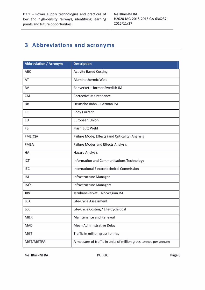
3 Abbreviations and acronyms
Abbreviation / Acronym Description
ABC Activity Based Costing
AT Aluminothermic Weld
BV Banverket – former Swedish IM
CM Corrective Maintenance
DB Deutsche Bahn – German IM
EC Eddy Current
EU European Union
FB Flash Butt Weld
FME(C)A Failure Mode, Effects (and Criticality) Analysis
FMEA Failure Modes and Effects Analysis
HA Hazard Analysis
ICT Information and Communications Technology
IEC International Electrotechnical Commission
IM Infrastructure Manager
IM’s Infrastructure Managers
JBV Jernbaneverket – Norwegian IM
LCA Life-Cycle Assessment
LCC Life-Cycle Costing / Life-Cycle Cost
M&R Maintenance and Renewal
MAD Mean Administrative Delay
MGT Traffic in million gross tonnes
MGT/MGTPA A measure of traffic in units of million gross tonnes per annum

D3.1 – Power supply technologies and practices of
low and high-density railways, identifying learning
points and future opportunities.
NeTIRail-INFRA H2020-MG-2015-2015 GA-636237 2015/11/27
NeTIRail-INFRA PUBLIC Page 9
Abbreviation / Acronym Description
MLD Mean Logistic Delay
MRT Mean Repair Time
MTTF Mean Time To Failure
NR Network Rail – British IM
ÖBB Österreichische Bundesbahnen – Austrian IM
OCL Overhead Contact Line
OCS Overhead Contact line System
OLE Overhead Line Equipment
PM Preventive Maintenance
RAM Reliability, Availability and Maintainability
RAMS Reliability, Availability, Maintainability and Safety
RCF Rolling Contact Fatigue (in this case usually related to head checks)
S&C Switches & crossings
SA Safety Analysis
TCDD Türkiye Cumhuriyeti Devlet Demiryolları – Turkish IM
TGV Train à Grande Vitesse (High Speed Train)
TSL Temporary Speed Limitation
UIC Union Internationale des Chemins (International Union of
Railways)
US/UT Ultra-Sonic / Ultra Sonic Testing
Vac Voltage with alternating current
Vdc Voltage with direct current
D3.1 – Power supply technologies and practices of
low and high-density railways, identifying learning
points and future opportunities.
NeTIRail-INFRA H2020-MG-2015-2015 GA-636237 2015/11/27
NeTIRail-INFRA PUBLIC Page 10
1 Railway power supply systems – general aspects
Electric power supply systems in railway networks have as their main function to perform electric
traction. Railway power supplies should ensure uninterrupted functioning, reliable and safe electric
vehicle traction. The power supply system includes all installations necessary for electrical traction
function. From systemic point of view the traction power supply is assured by:
The function of generating power supply;
The function of transmitting power supply;
The function of feeding power supply;
The function of collecting power supply by mobile electric vehicles.
A power supply system for the railways must provide electricity to locomotives and multiple units for
traction so these units can operate without having an on-board storage of energy, like diesel or
steam engines.
In the most frequently used system, the railway electricity power is supplied from the public high
voltage networks, through the individual traction substations with special role to convert high
voltage levels and sometimes nominal frequency of primary power supply parameters according to
the railway needs.
For example, German Railway (DB) and other European railway networks have traction power
provided by alternative current (AC) high voltage networks: AC 55 kV, AC 110 kV or AC 132 kV with
16.7 Hz frequency as input characteristics for traction power supply grid. The power distribution
function has a major role in power supply system for railways and is performed by the components
named power substations which realise the compatibility between high voltage grid network and
overhead contact lines.
Considering the evolution and diversity of railway electricity supply networks, a classification of
these can be achieved based on the component that makes contact and transfers energy between
the infrastructure and moving units. Taking as criteria for classification the contact type, the power
supply infrastructure can be divided into:
Overhead conductor wire infrastructure;
Third rail infrastructure;
Four rail;
Overhead conductor rail infrastructure;
Due to the great importance that the electricity supply system has, the following criteria must be
respected for the quality and safety of overhead lines:
Supply electricity without interruption to the pantograph of traction vehicles.
The railway network has to implement function of continuously absorbing regenerated
braking energy.

D3.1 – Power supply technologies and practices of
low and high-density railways, identifying learning
points and future opportunities.
NeTIRail-INFRA H2020-MG-2015-2015 GA-636237 2015/11/27
NeTIRail-INFRA PUBLIC Page 11
Comply with specified and standardized quality parameters for the voltages and frequency
at the pantographs of electric traction vehicles.
It should be noted that the electricity supply to the railway network differs from the supply network
power for public consumers due to the large variations absorbed in relatively short sections; this
variation is recorded actually at point level of overhead line that means high electrical stress for the
conductor section.
There are several different railway traction power supply systems in use throughout the world and
each system has different advantages in utilisation, robustness and cost effectiveness, and newest
electrification schemes require significant capital expenditure for installation.
D3.1 – Power supply technologies and practices of
low and high-density railways, identifying learning
points and future opportunities.
NeTIRail-INFRA H2020-MG-2015-2015 GA-636237 2015/11/27
NeTIRail-INFRA PUBLIC Page 12
2 Existing power supply systems - Classification
2.1 Characteristics of railway power supply systems
A railway power supply system provides electric power to rail vehicles without an on-board or local
fuel supply. This type of system to provide electric power has many advantages but at the same
time, requires significant capital expenditure. The selection of the type of solution is based on the
costs of energy supply, maintenance, and capital cost compared to the revenue obtained for freight
and passenger traffic. For freight and passengers transport, different electrification systems are used
for urban and intercity areas; some electric locomotives can switch to different supply voltages to
allow flexibility in operation.
Railway electrical system are characterised by:
Using electric locomotives to transport freight and passengers from one point to other, in
separated transport units (wagon) or electric multiple units - passenger cars with their own
motors;
Electricity is provided with efficiency and at high voltage, and power is provided from
dedicated generating stations; the energy is transmitted to the railway network and
distributed to the trains from power generating stations. The railway usually provides its
own distribution lines, switches and transformers;
Some electric railways have their own dedicated generating stations and transmission lines
but most railways purchase power from an electric utility;
The electric power is provided, for running trains, through a conductor placed in parallel to
the track that usually takes one of two technical solutions. First solution is an overhead wire
or catenary wire, suspended from poles or towers along the track or from existing structure
or tunnel ceilings. Locomotives or multiple units with electric traction get the power from
the contact wire with specific devices: pantographs, placed on their roofs, which press a
conductive strip against it with a spring or air pressure. The second solution is to use a third
rail, mounted at track level and making contact with traction unit by a sliding "pickup shoe"
or “contact shoe”. In most cases, overhead line and third-rail systems use the running rails as
the return path for current; however, some systems use a separate fourth rail for this
purpose;
Must operate at variable speeds. The speed is controlled through connecting the traction
motors used in combination by series or parallel. These are done by varying the traction
motors' fields, and limiting motor current;
Motors, generally have low voltage ratings. Early railway train technologies were supplied
with a relatively low DC voltage that the motors can use directly. Since utilities supply high
voltage AC as a standard for civilian and industrial consumers, in railways power traction
supply systems converter stations are used to provide low voltage DC (3kVdc or less). For
D3.1 – Power supply technologies and practices of
low and high-density railways, identifying learning
points and future opportunities.
NeTIRail-INFRA H2020-MG-2015-2015 GA-636237 2015/11/27
NeTIRail-INFRA PUBLIC Page 13
using direct current, for example on a 750 Vdc third-rail system, between power supply
stations is a distance about 2,5 km; between stations for 3 kVdc is about 7,5 km;
Modern high-speed railway projects have generally use high-voltage AC, when the
technology made up possible. Trend in current days is the DC routes have to be converted to
AC standard systems, excepting special situations.
2.2 Classification of electrification systems
Electrification systems are classified by three main parameters:
Voltage level of electricity power supply;
Current types used for electricity power supply: Direct current (DC), Alternating or
alternative current (AC), Frequency – for alternative current;
Contact system type with electricity power supply system: Overhead line (catenary), Third
rail, Fourth rail;
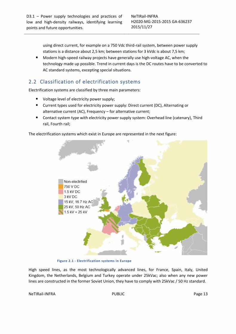
The electrification systems which exist in Europe are represented in the next figure:
Figure 2.1 - Electrification systems in Europe
High speed lines, as the most technologically advanced lines, for France, Spain, Italy, United
Kingdom, the Netherlands, Belgium and Turkey operate under 25kVac; also when any new power
lines are constructed in the former Soviet Union, they have to comply with 25kVac / 50 Hz standard.
D3.1 – Power supply technologies and practices of
low and high-density railways, identifying learning
points and future opportunities.
NeTIRail-INFRA H2020-MG-2015-2015 GA-636237 2015/11/27
NeTIRail-INFRA PUBLIC Page 14
2.3 Classification based on voltage level of electricity power supply
2.3.1 General considerations
Generally, the type of current used distinguishes between the various types of electrical energy
supply for moving railway vehicles.
The power supply systems are extremely diverse and heterogeneous and a classification of them can
be performed taking into account the most used voltages and frequencies. The classification is
independent of the type of contact used and refers only to voltage and frequency values, for AC
alternating signal.
There are many voltage systems used for railway electrification systems around the world, some of
them are presented in the tables below which covers both standard voltage and non-standard
voltage systems.
The voltages are nominal and vary depending on load and distance from the substations. Many
modern trams and trains use on-board solid-state electronics to convert these supplies to run three-
phase AC induction motors.
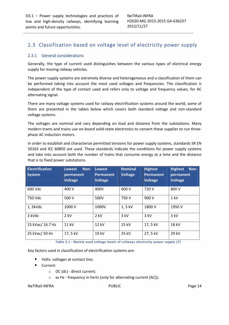
In order to establish and characterize permitted tensions for power supply systems, standards SR EN
50163 and IEC 60850 are used. These standards indicate the conditions for power supply systems
and take into account both the number of trains that consume energy at a time and the distance
that is to fixed power substations.
Electrification
System
Lowest Non-
permanent
Voltage
Lowest
Permanent
Voltage
Nominal
Voltage
Highest
Permanent
Voltage
Highest Non-
permanent
Voltage
600 Vdc 400 V 400V 600 V 720 V 800 V
750 Vdc 500 V 500V 750 V 900 V 1 kV
1, 5kVdc 1000 V 1000V 1, 5 kV 1800 V 1950 V
3 kVdc 2 kV 2 kV 3 kV 3 kV 3 kV
15 kVac/ 16.7 Hz 11 kV 12 kV 15 kV 17, 5 kV 18 kV
25 kVac/ 50 Hz 17, 5 kV 19 kV 25 kV 27, 5 kV 29 kV
Table 2.1 - Mainly used voltage levels of railways electricity power supply (7)
Key factors used in classification of electrification systems are:
Volts: voltages at contact line;
Current:
o DC (dc) - direct current;
o xx Hz - frequency in hertz (only for alternating current (AC));
D3.1 – Power supply technologies and practices of
low and high-density railways, identifying learning
points and future opportunities.
NeTIRail-INFRA H2020-MG-2015-2015 GA-636237 2015/11/27
NeTIRail-INFRA PUBLIC Page 15
o AC (ac) – alternating or alternative current; single-phase, except where marked
three-phase;
Conductors:
o overhead line;
o conductor rail, usually a third rail to one side of the running rails
top contact: oldest, least safe, affected by ice, snow and leaves;
side contact: newer, safer, less affected by ice, snow and leaves;
bottom contact: newer, safer, least affected by ice, snow and leaves;
Tables of the types of electrification systems can be found in “ANNEX 1: Power supply systems
related to power supply voltage and type of current”; here, tables with railway lines, representative
of electrification systems, with different supply voltages are presented.
2.4 Classification based on current types used for power supply system
2.4.1 Direct current (DC)
The most common DC voltages are 600 Vdc and 750 Vdc - for trams and metros; in the UK some
electrification systems still use electricity power supplies with 1.5 kVdc, 650 / 750 Vdc with third rail
and 3 kVdc with overhead line solution.
The lower voltages are often used with third or fourth rail systems, whereas voltages levels above
1kV are normally raised to overhead wiring for safety reasons.
Some exceptions are suburban trains (SBahn) lines in Hamburg, Germany. These operate using a
third rail with 1200 Vdc. The French SNCF Culoz-Modane line in the Alps used 1500 Vdc and a third
rail until 1976, when a catenary wire was installed and the third rail was removed.
Early electric systems used low-voltage DC. An advantage for direct current is electric motors which
can be fed directly from the traction supply and are controlled using a combination of resistors and
relays that connect the motors in parallel or series.
In the south of London, the supply uses continuous current at 750 Vdc, together with the third rail
contact feeding system while, for inner London, 650 Vdc is used to allow inter-running with London
Underground which uses a 650 Vdc with fourth rail system but with the fourth rail as centre rail.
The systems with DC current is relative simple but it requires thick cables and short distances
between railway electricity supply stations because of the high currents required.
The direct current solution involves major power losses through resistive consuming. In the United
Kingdom, 6800 A at 750 Vdc is the maximum current that can be drawn by a traction vehicle; for this
reason, on many cases, only a single locomotive can run inside a feeding section.
The distance between two electric feeder stations at 750 Vdc on third-rail systems is about 2.5 km.
The distance between two electric feeder stations at 3 kVdc is about 7.5km; this could be increased
D3.1 – Power supply technologies and practices of
low and high-density railways, identifying learning
points and future opportunities.
NeTIRail-INFRA H2020-MG-2015-2015 GA-636237 2015/11/27
NeTIRail-INFRA PUBLIC Page 16
even up to 25 km but with restriction for number of trains, in the same feeder section. Sometimes
auxiliary machinery, such as fans and compressors are powered by motors supplied directly from the
traction supply, for these extra insulation is needed for the relatively high operating voltage.
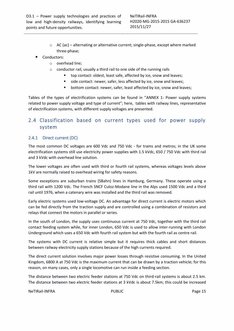
Other examples of DC electric power supply used are: systems supplied with 1500 Vdc which are
used in the Netherlands, Japan, Hong Kong, Ireland, Australia, France, New Zealand (Wellington) and
the United States. In Portugal, this system is used in the Cascais Line; in Denmark the 1500 Vdc
system is used on the suburban S-train system.
Figure 2.2 – United Kingdom railway power supply system that uses 1500 V dc
1.5 kVdc system was also used for suburban electrification in East London and Manchester, now
converted to 25 kVac.
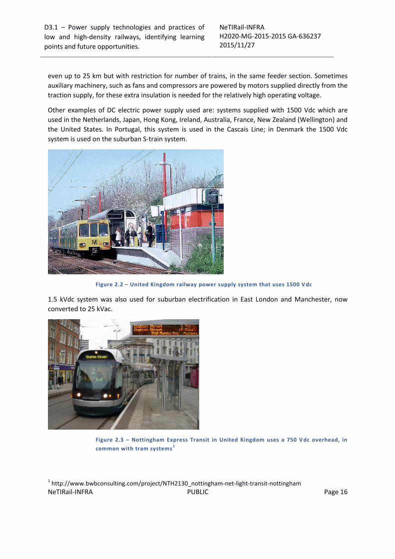
Figure 2.3 – Nottingham Express Transit in United Kingdom uses a 750 V dc overhead, in
common with tram systems1
1 http://www.bwbconsulting.com/project/NTH2130_nottingham-net-light-transit-nottingham
D3.1 – Power supply technologies and practices of
low and high-density railways, identifying learning
points and future opportunities.
NeTIRail-INFRA H2020-MG-2015-2015 GA-636237 2015/11/27
NeTIRail-INFRA PUBLIC Page 17
3 kVdc is used in Belgium, Italy, Spain, Poland, the northern Czech Republic, Slovakia, Slovenia,
western Croatia, South Africa and former Soviet Union countries (also using 25 kVac/ 50 Hz). It was
also formerly used by the Milwaukee Road's extensive electrification across the Continental Divide
and by the Delaware, Lackawanna & Western Railroad, in United States; now is converted to 25
kVac.
2.4.2 Alternative current (AC)
This category represents the overhead power supply system. Alternating current can be transformed
to lower voltages inside the locomotive. This allows much higher voltages and therefore smaller
currents along the line, which means smaller energy losses for long railways.
A variable of alternative current is frequency. This can have variation from region to region and is
depends on the installed infrastructure.
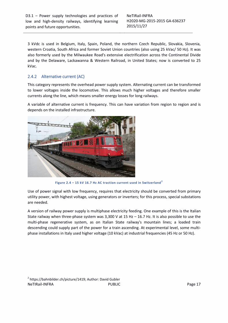
Figure 2.4 – 15 kV 16.7 Hz AC traction current used in Switzerland2
Use of power signal with low frequency, requires that electricity should be converted from primary
utility power, with highest voltage, using generators or inverters; for this process, special substations
are needed.
A version of railway power supply is multiphase electricity feeding. One example of this is the Italian
State railway when three-phase system was 3,300 V at 15 Hz – 16.7 Hz. It is also possible to use the
multi-phase regenerative system, as on Italian State railway's mountain lines; a loaded train
descending could supply part of the power for a train ascending. At experimental level, some multi-
phase installations in Italy used higher voltage (10 kVac) at industrial frequencies (45 Hz or 50 Hz).
2 https://bahnbilder.ch/picture/1419; Author: David Gubler
D3.1 – Power supply technologies and practices of
low and high-density railways, identifying learning
points and future opportunities.
NeTIRail-INFRA H2020-MG-2015-2015 GA-636237 2015/11/27
NeTIRail-INFRA PUBLIC Page 18
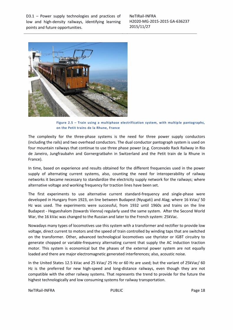
Figure 2.5 – Train using a multiphase electrification system, with multip le pantographs,
on the Petit trains de la Rhune, France
The complexity for the three-phase systems is the need for three power supply conductors
(including the rails) and two overhead conductors. The dual conductor pantograph system is used on
four mountain railways that continue to use three phase power (e.g. Corcovado Rack Railway in Rio
de Janeiro, Jungfraubahn and Gornergratbahn in Switzerland and the Petit train de la Rhune in
France).
In time, based on experience and results obtained for the different frequencies used in the power
supply of alternating current systems, also, counting the need for interoperability of railway
networks it became necessary to standardize the electricity supply network for the railways; where
alternative voltage and working frequency for traction lines have been set.
The first experiments to use alternative current standard-frequency and single-phase were
developed in Hungary from 1923, on line between Budapest (Nyugati) and Alag; where 16 kVac/ 50
Hz was used. The experiments were successful, from 1932 until 1960s and trains on the line
Budapest - Hegyeshalom (towards Vienna) regularly used the same system. After the Second World
War, the 16 kVac was changed to the Russian and later to the French system: 25kVac.
Nowadays many types of locomotives use this system with a transformer and rectifier to provide low
voltage, direct current to motors and the speed of train controlled by winding taps that are switched
on the transformer. Other, advanced technological locomotives use thyristor or IGBT circuitry to
generate chopped or variable-frequency alternating current that supply the AC induction traction
motor. This system is economical but the phases of the external power system are not equally
loaded and there are major electromagnetic generated interferences; also, acoustic noise.
In the United States 12.5 kVac and 25 kVac/ 25 Hz or 60 Hz are used; but the variant of 25kVac/ 60
Hz is the preferred for new high-speed and long-distance railways, even though they are not
compatible with the other railway systems. That represents the trend to provide for the future the
highest technologically and low consuming systems for railway transportation.
D3.1 – Power supply technologies and practices of
low and high-density railways, identifying learning
points and future opportunities.
NeTIRail-INFRA H2020-MG-2015-2015 GA-636237 2015/11/27
NeTIRail-INFRA PUBLIC Page 19
Apart from a few cases, almost all AC traction units draw alternating current from an overhead line.
At present at least 30% length of the world rail networks was electrified and at least 60% of all rail
transport is carried by electric traction.
2.4.3 Mixing electricity power supply systems
Because of the variety of railway electrification systems, which can vary even within a country, trains
often have to pass from one system to another. One way to accomplish this is by changing
locomotives at the switching stations. These stations have overhead wires that can be switched from
one voltage to another and so the train arrives with one locomotive and then departs with another.
The switching stations have very sophisticated components and they are very expensive. The other
disadvantage is the extra time waiting for the changing locomotives; this time is added to the trip
and is not acceptable for high speed railways and busy passenger lines.
Other solution is to use locomotives with multi-system voltages tractions; can operate under few
types of voltages, current and frequency types. For Europe, four system locomotives are considered:
1.5 kVdc, 3 kVdc, 15 kVac/ 16.7Hz, 25 kVac/ 50 Hz).
These locomotives advantages are they do not stop when passing from one electrification system to
other, the changeover is done when the train coasts for a short time. Eurostar trains through the
Channel Tunnel are a multi system; a significant part of the route near London used to be on
southern England's 750 Vdc third rail system, the route into Brussels is 3 kVdc but overhead line
system, while the rest of the route is 25 kVac/ 50 Hz overhead line system.
Another combination is to use electro-diesel locomotives type, which can operate as an electric
locomotive on electrified lines but have a diesel engine for non-electrified sections; that solution has
been used in several countries.
United Kingdom - The first line systems were as third rail, low voltage, mainly 600 Vdc and 750 Vdc;
these were combined with DC or AC overhead line.
Southern England has overhead and third rail dual-system locomotives and multiple units to allow
running between 750 Vdc as third rail for south of London and the 25 kVac/ 50Hz overhead line
system for north and east of London.
Starting with the West Coast Mainline electrification in the 1960s, the 25 kVac/ 50Hz overhead line
system was adopted for all further mainline electrified lines in the UK; exceptions are extensions to
other existing systems having third rail lines, for compatibility reasons.
The "Automatic Power Control" system was developed to allow trains to automatically switch
between voltages, whilst moving. The driver has to close the power and coast clear of the neutral
section. Then, the system automatically opens the circuit breaker, detects a change in voltage and
switches over the transformer to the correct input voltage setting, then closes the circuit breaker.
Italy - Italian railways have systems with overhead power supply lines from a catenary, for 3 kVdc
voltage and for 25kVac/ 50Hz. The last version of the system is used on the new high speed lines.

D3.1 – Power supply technologies and practices of
low and high-density railways, identifying learning
points and future opportunities.
NeTIRail-INFRA H2020-MG-2015-2015 GA-636237 2015/11/27
NeTIRail-INFRA PUBLIC Page 20
Spain - Spanish railways have two systems with overhead supply, from a catenary: 3 kVdc and 25
kVac/ 50Hz; this last system is installed on the high speed lines.
Czech Republic and Slovakia - In the Czech Republic also in Slovakia, the railways power supply
systems have 3 kVdc and 25 kVac/ 50Hz systems but there are no switching stations - the two
systems meet at simple breaks on overhead wires. From these breaks, there are two stations (Kutná
Hora and Nedakonice).
United States - In the United States, multi system ALP- 44 and ALP- 46 locomotives (New Jersey
Transit) are used; Amtrak company uses multi-system AEM-7, HHP-8 and Acela locomotives for
service into New York and Northeast Corridor, between Washington and Boston.
In these cases, trains run on both the newer system of 25 kV at 60 Hz and the older system of 12 kV
at 25 Hz.
Figure 2.6 – New Jersey Transit ALP-46 AC locomotive based on the DBAG Class 1013
India – 1.5 kVdc and 25 kVac/ 50 Hz are used. The alternative current is provided for main line trains.
As particularity, the 1.5 kVdc overhead system with negative earth and positive current for catenary
is used around Mumbai, but there are plans to change this to 25 kVac as its more efficient and with
no excessive cost for translation. The 25 kVac system with overhead lines is used almost throughout
the rest of the country. Now the dual-voltage WCAM series locomotives are running as intercity
trains for Mumbai and suburban regions. These EMU variants are designed to be powered by DC and
AC currents.
South Africa - South Africa has sections of dual system track, both 3 kVdc and 25 kVac/ 50Hz.
3 http://www.wikiwand.com/es/Locomotora_electrica

D3.1 – Power supply technologies and practices of
low and high-density railways, identifying learning
points and future opportunities.
NeTIRail-INFRA H2020-MG-2015-2015 GA-636237 2015/11/27
NeTIRail-INFRA PUBLIC Page 21
3 Technical, functional and quality characteristics for power supply systems
This Chapter will present technical and functional characteristics of power supply systems for
railways. Also analysed are quality issues – reliability, efficiency, security, safety, and performances –
that these systems introduce when used in the railway infrastructure.
3.1 General requirements
Reliability in operation electrified railway networks depends largely on the availability and reliability
of the electricity traction supply system. Contact line requirements – even overhead line or third rail
- must take into account the contact line is the only component of the power supply system cannot
be installed redundant, from economic and technical reasons. Requirements on contact line system
should fulfil the following functions:
Electric power supply distribution should be done reliably over a certain distance;
Providing a sliding contact current collector, reliable in all conditions;
The need for high availability contact line systems requires a planning cycle as detailed as possible
for electrification of railway sections or networks. This planning should include only verified
technical solutions to be accepted in the system, tested equipment with long life with easy
installation and low maintenance costs during exploitation. The following basic requirements must
be met in the design of an installation of the contact line:
People but also sensitive equipment must not be endangered by operation of the contact
line.
Project solution must ensure that power transmission interruptions do not occur in normal
operation, up to the maximum permitted speed for the type of contact line considered in
the project. This applies whatever type of dynamic interaction of the current collector:
overhead contact line or third rail.
System components must have a production quality that would ensure a long life.
The following requirements are important:
o Suitable electrical and mechanical strength;
o Durability to weights and torsion due to wind and ice or other aggressive substances
in the air;
o Increased corrosion resistance components;
o Assures a uniform wear and as low as possible wear for the contact line.
During the design of the overhead power line, particular conditions and restrictions must be
observed and respected. These are external, generated by residential areas, special
construction zones, areas with existing overhead supply networks, historical and aesthetic
aspects of cities must be respected, etc.
D3.1 – Power supply technologies and practices of
low and high-density railways, identifying learning
points and future opportunities.
NeTIRail-INFRA H2020-MG-2015-2015 GA-636237 2015/11/27
NeTIRail-INFRA PUBLIC Page 22
Environmental protection has to be respected.
The costs for initial investment and installation, for operation and maintenance during the
cycle life of the equipment, should be as low as possible.
The individual characteristics derived from these basic requirements of a contact line system, can be
classified into mechanical, electrical, environmental, operational and maintenance-related aspects;
but a strict distinction between the individual requirements is not always possible.
3.2 Characteristics of railway power supply systems
3.2.1 Advantages
In comparison to the principal alternative of diesel locomotion, the electric railways offer
substantially better energy efficiency, lower emissions and lower operating costs. Electric
locomotives are usually quieter, more powerful, and more responsive and reliable than diesels and
have no local emissions, an important advantage in tunnels and urban areas. There are electric
traction systems which provide regenerative braking that turns the trains braking energy back into
electricity and returns it to the supply system to be used by other trains or the general utility grid.
Compared to other railway traction systems, electric traction has the main advantage of a higher
power to weight ratio than other forms of traction: diesel or steam engines that generate power on
board. Power supply allows rapid acceleration and less towing effort on steep slopes. In addition,
locomotives equipped with regenerative braking when the speed drops, power generated are sent
back into the supply system or is used local in place of main energy supply; ex. heating or lighting
systems for passenger cars.
Relative to the list of advantages that electricity supply systems for railways bring, those related to
the environment and quality of service should be mentioned. These include lack of exhaust gases of
diesel locomotives, much less noise and much lower volume of activity for maintaining traction
units. Given the large and growing density of traffic, especially at passengers travelling, electric
trains produce less carbon emissions than diesel trains. This has economic importance in countries
where fossil energy resources are low and not sufficient.
To summarize, the benefits can be grouped as follows:
Lower operating costs for traction locomotives and multiple units;
Lower maintenance costs for traction locomotives and multiple units;
Greater power to weight ratio, resulting in fewer locomotives used for the same amount
transported;
Faster acceleration resulting in shorter travel times;
Upper limit of the effective power supplied is higher;
Maximum speed limit is also higher;
Less noise pollution;
No power loss at high altitudes;
Less dependence on fossil fuels;

D3.1 – Power supply technologies and practices of
low and high-density railways, identifying learning
points and future opportunities.
NeTIRail-INFRA H2020-MG-2015-2015 GA-636237 2015/11/27
NeTIRail-INFRA PUBLIC Page 23
Environmental pollution is greatly reduced, even when the electricity is produced by fossil
fuel plants.
Provide some level of independence of running costs from fuel prices and decreasing fuel
reserves.
It is the only solution for the underground stations, where trains with diesel traction cannot
operate because of safety reasons
More comfortable ride on multiple units because electric engines are smoother than diesel
engines
3.2.2 Disadvantages
The disadvantages of electric traction are the high initial investment that may be uneconomic on
lightly trafficked routes, a relative lack of flexibility since electric trains need electrified tracks or on-
board and charging infrastructure at stations, and a vulnerability to power interruptions.
In different regions, relating mainly to historical reasons, different supply systems voltages and
frequencies are used, involving expensive costs for services and operational activities.
Highest voltages at contact line level and third rails are a hazard for railway workers, passengers, and
other people and animals. Overhead contact lines are considered safer than third rails, because of
distance and hard accessibility, but it is often considered not aesthetic.
The main disadvantage of old existing railways to be upgraded by electrification and also for new
railway network that will be built is the significant costs needed. These costs are especially
significant, to existing poorly used secondary lines.
Due to the low income, the investor return after future exploitation is unlikely to recover; thus, their
investment is in danger. In these situations, secondary lines are unlikely to achieve modernization
and electrification of railways unless the costs are covered by public authorities.
Special situations can occur when forecasting the industrial development of a region without
developed urban infrastructures; in this case, the phenomenon of transport by rail of commuters
can encourage investment in electrification of the railway networks.
Another situation is the development of investment in other areas that require a massive increase in
freight transport, like: new mining exploitations, harbours modernization, etc.
Some cost targets for modernization of existing railway involve clearance. That means alterations on
obstructions like tunnels and bridges; also, modifications or upgrades will be needed on the railway
signalling for new traffic characteristics.
To summarize, the disadvantages can be grouped as follows: electrification initial and continuous
maintenance cost; electrical load for existing and limited power grid; un esthetical appearance of the
overhead line structures and cabling; fragility and also vulnerability because the overhead
electrification systems suffer severe interruptions due to minor mechanical faults; theft events are
significate because of high value of material used in power supply system’s infrastructure.
D3.1 – Power supply technologies and practices of
low and high-density railways, identifying learning
points and future opportunities.
NeTIRail-INFRA H2020-MG-2015-2015 GA-636237 2015/11/27
NeTIRail-INFRA PUBLIC Page 24
3.2.3 Acceptable compromises
Maintenance costs of the lines will be increased when upgraded to electrification, there are
additional maintenance costs associated with the electrical equipment. Relative to the maintenance
cost, all infrastructure managers and rolling stock operators claim lower maintenance costs as
principal condition for new investments.
Modernization of the railway network by introducing electrical power supply capacity, has an effect
opposite to the one desired relative to maintenance costs, they will grow. The only argument for
accepting investment is the demonstration that will get high enough income to cover increased
maintenance costs and retain net worth higher than earlier gains.
A main reason for electrification is networks compatibility. When electrifying a line, the compatible
connections with other railway lines must be considered.
Depending on the situations to be examined the option for changing locomotive, to transition from
one section to another railway section: electrified – none electrified should be considered. That will
produce time delay and additional operational cost for manoeuvres but may be accepted if there is a
benefit.
If travel times are very important, for example in the case of passenger transportation more
expensive locomotives with dual mode engines should be used.
Different traction modes for sections in a railway network is an issue for long distance trips, but
many lines come to be dominated by traffic from long freight trains (usually running coal, or
containers to or from ports). These trains could get advantages and savings through electric power
supply, but it can be too costly to extend electrification to isolated areas, and unless an entire
network is electrified, companies often find that they need to continue using diesel trains even if
some sections are electrified.
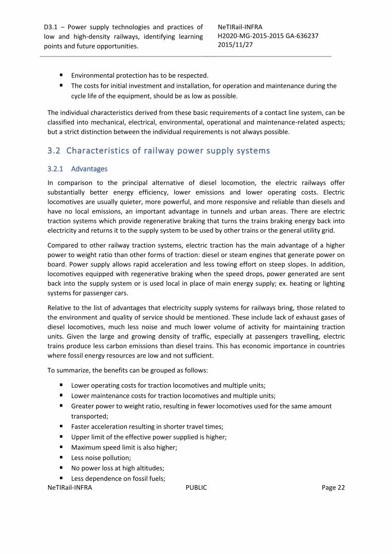
Figure 3.1 – Most overhead electrification do not allow sufficient clearance for a double -
stack car4
4 http://www.wig-wag-trains.com/KatoPages/Freight/Gunderson-Maxi-IV_Page.html

D3.1 – Power supply technologies and practices of
low and high-density railways, identifying learning
points and future opportunities.
NeTIRail-INFRA H2020-MG-2015-2015 GA-636237 2015/11/27
NeTIRail-INFRA PUBLIC Page 25
An important part of railways operations is freight transportation that have increasing demand for
container traffic. This is more efficient when double-stack goods containers are used; this may not
be possible because the characteristics of insufficient clearance of overhead lines, the system may
have to be modified to have sufficient height, at supplementary cost.
Negative implications are given by the connection problems between different power supply
standards for intercity lines, and local area electrified sections, providing local services, for example
commuter traffic; there may be differences even between the electrification of commuter lines that
operate at different standards. This can cause increased costs because of difficulty with section
connecting.
Some lines have come to be overlaid with multiple electrification standards for complying with
different feeding systems of trains. This is a solution to avoid replacing the existing rolling stock on
those lines. There are situations where diesel trains are running along completely electrified routes
and this can be due to incompatibility of electrification standards along the route.
Related to goals of NeTIRail project, especially for low density rural or secondary lines, electrification
may not be feasible (especially using newest technologies, e.g. regenerative braking), because lower
running cost of trains may be overcome by the higher costs of maintenance. Therefore, most long-
distance lines in North America and many countries are not profitable to be electrified due to
relatively low frequency of running trains.
Electric locomotives may provide greater power output than most diesel locomotives, in some cases
for passenger operation it is possible to provide enough power with diesel engines but if it
performance and higher speeds are needed, diesel traction is not feasible; therefore, almost all high
speed trains in the world have electric power traction.
Also, for freight transportation, the same arguments exist; power of electric locomotives gives them
the possibility to transport higher freight weights at higher speed; in present and for the future,
increasing speed will increase the capacity of railway transport, mostly when the time between
trains it is a restricted factor.
3.2.4 Energy efficiency
It is obvious that electric trains are more energy efficient than diesel trains; also produce less
pollution having a smaller carbon dioxide footprint. The main reasons are:
The electric trains are lighter than diesel variant because they do not have to carry the
weight of a motor that turns the fossil fuel into traction energy; Electric trains receive direct
energy by overhead lines and do not need to carry fuel. However, the weight of electrical
control equipment should be considered, mainly the weight of the transformer.
The electric power can be generated from various energy sources that are more efficient
than the one generated by a diesel engine. Thus, electric trains also have the advantage of
decreasing the dependence by the oil products and reduce carbon dioxide emissions. The list
of these alternative sources can include: nuclear, renewable energy sources (hydro, wind,
hydrothermal, etc.).

D3.1 – Power supply technologies and practices of
low and high-density railways, identifying learning
points and future opportunities.
NeTIRail-INFRA H2020-MG-2015-2015 GA-636237 2015/11/27
NeTIRail-INFRA PUBLIC Page 26
An important advantage of electric traction systems is that significant power can be
obtained from regenerative braking in certain circumstances, with the appropriate
equipment. These energy sources can be fed back into the power supply railway network
and used by other vehicles in the same section. The solution is effective if there is a high
density of electric rolling stock in a section. In case of electrified railway lines in mountain
areas, trains can be programmed so that the climb of a train is helped by a train that
descends and brakes. In other cases, renewable energy is collected and used later in the
same section of railway network, for example for accelerating trains stopped in stations.
Some systems, for example in the UK there are systems based on the voltage of 25 kVac, are
able to load renewable energy into the public network.
Worldwide reserves of fossil fuel energy are decreasing very rapidly. Thus it is estimated that oil
reserves can be still used approximately 42 years; gas reserves are estimated at 167 years; coal
reserves are estimated at 416 years. Most industrialized countries, with important railway networks
do not have reserves of fossil fuels or have exhausted most of their reserves in the process of
industrial development – for example, USA and UK. These countries, to keep their level of
development, will generate a trend of replacing traditional energy with clean energy.
Railway electrification process is often considered a successful experience in reforming energy
sources. It can reduce pollution and the greenhouse effect, in accordance with the Kyoto Protocol. In
addition, lower energy costs are advantages to introducing the electrification on railway networks.
Other benefits of electrification are increased productivity of railway infrastructure as well as rolling
stock (i.e. locomotives and wagons) through continuous R&D activities. Research and development
in the electrified railway sector involve technical areas such as: electrical engineering, electronics
and automation. Good results were achieved by adopting technologies like GTO (gate turn-off
thyristor) or IGBT (insulated gate bipolar transistor) that resulted in increasing the power traction
and operational reliability of locomotives.
3.3 Overhead line
Overhead lines represent a system used to transmit electrical energy to trains from the energy
supply point.
The mechanics of power supply wiring it is not simple. Hanging a wire over the track which provides
current and allow trains to run under it is not so easy if it provides the reliability to justify the
expense of its installation.
The wire must be able to carry the current (several thousand amperes), to remain in line with the
route, and to withstand wind even if this reaches 200 km/h, extreme cold and heat, and other
hostile weather conditions.
Overhead catenary systems, named "catenary" due to the form of the curve of the supporting cable,
have a complex geometry. The contact wire has to be held horizontally in tension and pulled laterally
to negotiate curves in the track and the contact wire tension is in the region of 2 tones. The length of

D3.1 – Power supply technologies and practices of
low and high-density railways, identifying learning
points and future opportunities.
NeTIRail-INFRA H2020-MG-2015-2015 GA-636237 2015/11/27
NeTIRail-INFRA PUBLIC Page 27
wire is between 1000 and 1500 meters, depending on the temperature ranges. The wire is zigzagged
relative to the centre line of the track to equally wear the train's pantograph.
A tram depot may have just a single wire hung directly from insulated supports. In a slow speed
depot environment, it is necessary that the wire can be seen to rise and fall when a pantograph
passes along it.
The contact wire (see Figure 3.2) is grooved to allow a clamp to attach the dropper wire to be fixed
on the top side. The tension of the wire is maintained by weights suspended at each end of its
length. Each length is overlapped by its neighbour to ensure a smooth passage for the pantograph.
The pantograph head starts to bounce if the tension is incorrect and trains have a wrong speed. An
electric arc occurs with each bounce so that the pantograph and the wire will wear under such
conditions.
Figure 3.2 – Contact wire cross section
A similar problem can appear when a train has more than one pantograph when the leading
pantograph head sets up a wave in the wire and the rear head cannot stay in contact. High speeds
increase the wave.
D3.1 – Power supply technologies and practices of
low and high-density railways, identifying learning
points and future opportunities.
NeTIRail-INFRA H2020-MG-2015-2015 GA-636237 2015/11/27
NeTIRail-INFRA PUBLIC Page 28
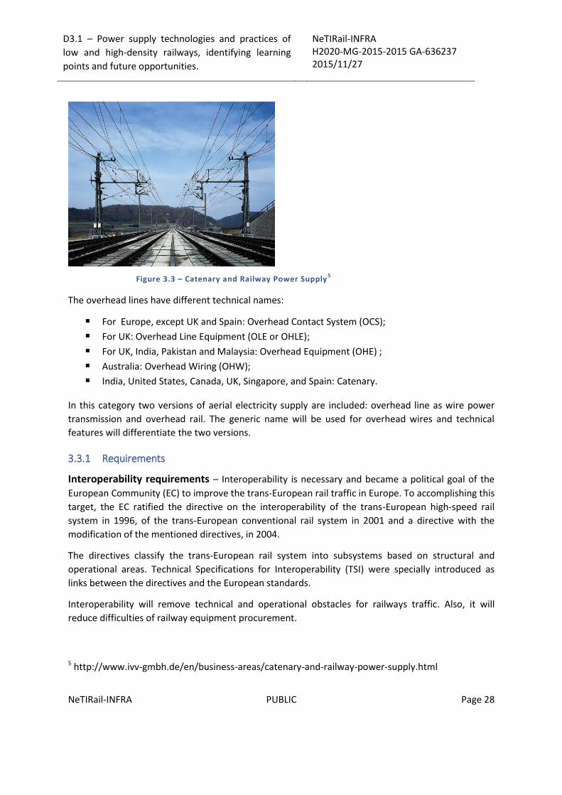
Figure 3.3 – Catenary and Railway Power Supply5
The overhead lines have different technical names:
For Europe, except UK and Spain: Overhead Contact System (OCS);
For UK: Overhead Line Equipment (OLE or OHLE);
For UK, India, Pakistan and Malaysia: Overhead Equipment (OHE) ;
Australia: Overhead Wiring (OHW);
India, United States, Canada, UK, Singapore, and Spain: Catenary.
In this category two versions of aerial electricity supply are included: overhead line as wire power
transmission and overhead rail. The generic name will be used for overhead wires and technical
features will differentiate the two versions.
3.3.1 Requirements
Interoperability requirements – Interoperability is necessary and became a political goal of the
European Community (EC) to improve the trans-European rail traffic in Europe. To accomplishing this
target, the EC ratified the directive on the interoperability of the trans-European high-speed rail
system in 1996, of the trans-European conventional rail system in 2001 and a directive with the
modification of the mentioned directives, in 2004.
The directives classify the trans-European rail system into subsystems based on structural and
operational areas. Technical Specifications for Interoperability (TSI) were specially introduced as
links between the directives and the European standards.
Interoperability will remove technical and operational obstacles for railways traffic. Also, it will
reduce difficulties of railway equipment procurement.
5 http://www.ivv-gmbh.de/en/business-areas/catenary-and-railway-power-supply.html

D3.1 – Power supply technologies and practices of
low and high-density railways, identifying learning
points and future opportunities.
NeTIRail-INFRA H2020-MG-2015-2015 GA-636237 2015/11/27
NeTIRail-INFRA PUBLIC Page 29
The main advantage of interoperability achievement refers to high-speed technology trains. These
have to be designed to guarantee safe, uninterrupted travel through different sections: to reach at
least 250 km/h speed on lines specially built for high speed and enabling speeds of over 300 km/h to
be reached in future development and appropriate circumstances; to get a speed in the order of 200
km/h for existing lines but which have been specially upgraded.
According to the definition, high-speed trains are those designed for 250 km/h and greater speeds.
The high-speed lines cover three categories:
Category line I (high speed lines) - special built category for high-speed lines; there are
equipped for speeds equal or greater than 250 km/h;
Category line II (upgraded lines) - upgraded high-speed lines for speeds around of 200 km/h;
Category line III (connecting lines) - specially upgraded high-speed lines with special features
for topographic characteristics, town-planning constraints; on these situations the speed is
adapted to each case.
As a consequence, the existing standards EN 50 163 and EN 50 119 evolved. New standards were
established:
EN 50 388 on technical criteria for the coordination between power supply and rolling stock
to achieve interoperability;
EN 50 367 on technical criteria for the interaction between pantograph and overhead
contact line;
EN 50 317 on the requirements for validation of measurements of the dynamic interaction
between pantograph and contact line;
EN 50 318 on the validation of simulation of the dynamic interaction between pantograph
and overhead contact line.
The TSI establishes provisions for subsystems and their component have to be complied when
designing the overhead contact lines for high-speed installations; it contains essential requirements
concerning safety, reliability, availability and maintainability, health, environmental protection and
technical compatibility. Strict application of the specification guarantees the compliance of the
installation with the essential requirements of the TSI.
Requirements from costs point of view – The costs for investments in construction, operation
and maintenance of overhead contact line systems should be as low as possible for the entire service
life. The components and devices should be reliable and require low cost maintenance. The entire
system should be designed for a long service life, for these should be adopted, for example corrosion
protection measures. Electrical components and mechanical elements have to be easy to install and
easy to change when is needed.
For reducing the contact wire wear and the pantograph wear quality and suitable materials
combinations should be used; the design stage is very important in this aspect. If it is possible,

D3.1 – Power supply technologies and practices of
low and high-density railways, identifying learning
points and future opportunities.
NeTIRail-INFRA H2020-MG-2015-2015 GA-636237 2015/11/27
NeTIRail-INFRA PUBLIC Page 30
separate poles for each track should be used. The contact line should be designed so that the
periods of line closure for planned maintenance or to repair contact lines and tracks are kept low.
Mechanical requirements – Technical and functional characteristics for power supply lines from
mechanical point of view, take into account the strength and quality of the wires, stranded
conductors and other elements. To gain reliable interaction from the contact line or third rail and
the current collector (pantograph collector, shoe collector, etc.) defined clearances between the
contact line or third rail and the rails have to be specified. The height of the contact wire is specified
according to the type of railway and field of application. The minimum contact wire height, the
maximum contact wire height and the permissible contact wire gradient are all important.
During normal operational activities, the forces in stranded conductors, wires and other components
have to be kept within permissible limits. The sag of conductors has not to exceed permissible values
for safety of people and operations, also maintenance activities. When the required safety clearance
or the minimum clearance is breached, danger situations may arise. Minimum free air space, to
energized parts, has to be maintained under all operating conditions, such as different positions due
to pantograph moving and different sags, this involves variable heights of overhead lines. The wind
and ice loads when this situation appears against the conductors and other elements should not
have a negative effect on railway operations.
For uniform and low wear of the pantograph collector strips and the contact wire, these contact
wires need to be places at lateral offset to the track centre line, called stagger. All mechanical loads
acting on the overhead contact line must be carried by the poles and foundations and transmitted
reliably to the subsoil. Deformation of parts such as bending of poles or any incurred resonant
vibrations should not affect the transmission of power.
The overhead contact line has to comply with electrical quality criteria for successful power
transmission. Quality criteria such as elasticity and its uniformity along the span and contact wire
uplift have to be considered. The dynamic quality criteria include the wave propagation velocity, the
Doppler factor and the reflection factor. The contact force as a function of the running speed and its
standard deviation are also significant quality features. Overhead contact lines, shall also be capable
of allowing operation of trains that contact two or more pantographs at the same time.
Electrical requirements – From this point of view significant characteristics are the type of current
and the nominal voltage. A principal characteristic for the performance of an electrified line is the
capacity of current carried by the contact line system. In comparison with industrial or public
distribution systems of power supply, short-circuits occur more frequently in contact line networks.
Therefore, the short circuit current capacity of a contact line system is also a determining feature.
In addition, as an obligatory condition, the voltage of the overhead line network has to be
maintained within designed limits under all normal operating conditions. The losses during power
transmission also have to be maintained within acceptable limits.
Minimizing the effects of frequent faults on railway operations, overhead contact line installations
need to be divided into distinct sections. Additionally, it is important that every designed installation
allow faults to be quickly and precisely localized. If conductors or other components of overhead

D3.1 – Power supply technologies and practices of
low and high-density railways, identifying learning
points and future opportunities.
NeTIRail-INFRA H2020-MG-2015-2015 GA-636237 2015/11/27
NeTIRail-INFRA PUBLIC Page 31
contact line installations fail, defined fault conditions should occur which allow a correct
determination of the fault condition.
The insulation should be accommodated by associating insulating materials and their design to
requirements and by respecting defined minimum air gaps. Protective measures should be effective
to avoid exposing any person to the possibility of electric shock.
Important considerations should be taken into account related to impacts against the public energy
network, e.g. harmonic frequencies and electromagnetic fields should be as low as possible. The
transmission of power through the contact line network can cause interference to adjacent lines of
all kinds through inductive, capacitive and galvanic coupling. In direct current railways, extensive
measures are necessary to limit current corrosion. Rail-to-earth voltages occurring in operation or
under fault conditions may not exceed permissible limits.
Environmental requirements – Power supply systems have to be reliable and to function
according with the technical characteristics. One of the most important characteristics is
temperature range; this is defined as ambient temperature: -30 °C to 40 °C for Central Europe, -30
°C to 45 °C for Spain, etc. According with standard EN 50125-2 are specified environmental
conditions to be accommodated by the design of overhead contact lines. Lateral deflections of
contact lines are caused by wind loading, which in turn could lead to the pantograph de-wiring under
extreme conditions. For this reason, contact lines have to be designed for particular wind velocities,
under which operation are considered. Beyond this, extreme wind loads should not lead to
mechanical damage of the contact line installation itself. The magnitude of the wind velocities, upon
which the design is based, is agreed with the railway company or authorities or taken from EN 50
125-2.
The ice accretion on contact line has to be taken into account in the design, especially when this
phenomenon is frequent. Atmospheric precipitation, aggressive vapours, gases and dust are to be
taken into account when determining the electrical values and the life expectancy of components
and elements.
Relating to the insulating materials and other elements in the contact line installation, the properties
should not be altered by climatic impacts and sunlight other else the operational life cycle could be
affected.
3.3.2 Components of overheads contact line system
Overheads contact line system have the principal function to make contact through electrical wires
or conductor rails with a sliding current collector, to supply electrical energy to railway vehicles. For
this reason, it is frequently named Overhead Contact Line System. The contact line is considered to
include insulators and these are classed as being part of the electrical system in contact with high
voltages.
Overhead contact line systems include:
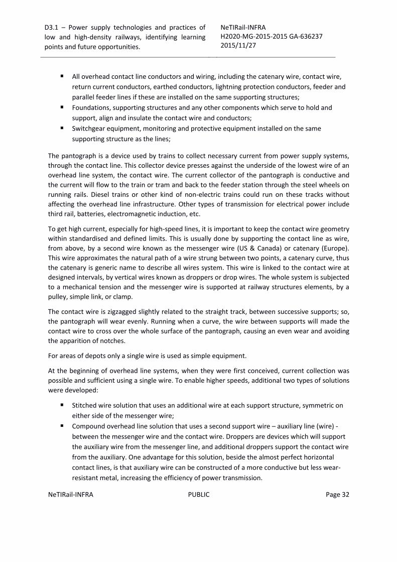
D3.1 – Power supply technologies and practices of
low and high-density railways, identifying learning
points and future opportunities.
NeTIRail-INFRA H2020-MG-2015-2015 GA-636237 2015/11/27
NeTIRail-INFRA PUBLIC Page 32
All overhead contact line conductors and wiring, including the catenary wire, contact wire,
return current conductors, earthed conductors, lightning protection conductors, feeder and
parallel feeder lines if these are installed on the same supporting structures;
Foundations, supporting structures and any other components which serve to hold and
support, align and insulate the contact wire and conductors;
Switchgear equipment, monitoring and protective equipment installed on the same
supporting structure as the lines;
The pantograph is a device used by trains to collect necessary current from power supply systems,
through the contact line. This collector device presses against the underside of the lowest wire of an
overhead line system, the contact wire. The current collector of the pantograph is conductive and
the current will flow to the train or tram and back to the feeder station through the steel wheels on
running rails. Diesel trains or other kind of non-electric trains could run on these tracks without
affecting the overhead line infrastructure. Other types of transmission for electrical power include
third rail, batteries, electromagnetic induction, etc.
To get high current, especially for high-speed lines, it is important to keep the contact wire geometry
within standardised and defined limits. This is usually done by supporting the contact line as wire,
from above, by a second wire known as the messenger wire (US & Canada) or catenary (Europe).
This wire approximates the natural path of a wire strung between two points, a catenary curve, thus
the catenary is generic name to describe all wires system. This wire is linked to the contact wire at
designed intervals, by vertical wires known as droppers or drop wires. The whole system is subjected
to a mechanical tension and the messenger wire is supported at railway structures elements, by a
pulley, simple link, or clamp.
The contact wire is zigzagged slightly related to the straight track, between successive supports; so,
the pantograph will wear evenly. Running when a curve, the wire between supports will made the
contact wire to cross over the whole surface of the pantograph, causing an even wear and avoiding
the apparition of notches.
For areas of depots only a single wire is used as simple equipment.
At the beginning of overhead line systems, when they were first conceived, current collection was
possible and sufficient using a single wire. To enable higher speeds, additional two types of solutions
were developed:
Stitched wire solution that uses an additional wire at each support structure, symmetric on
either side of the messenger wire;
Compound overhead line solution that uses a second support wire – auxiliary line (wire) -
between the messenger wire and the contact wire. Droppers are devices which will support
the auxiliary wire from the messenger line, and additional droppers support the contact wire
from the auxiliary. One advantage for this solution, beside the almost perfect horizontal
contact lines, is that auxiliary wire can be constructed of a more conductive but less wear-
resistant metal, increasing the efficiency of power transmission.
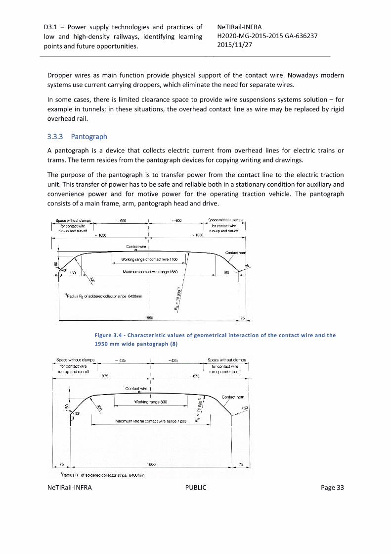
D3.1 – Power supply technologies and practices of
low and high-density railways, identifying learning
points and future opportunities.
NeTIRail-INFRA H2020-MG-2015-2015 GA-636237 2015/11/27
NeTIRail-INFRA PUBLIC Page 33
Dropper wires as main function provide physical support of the contact wire. Nowadays modern
systems use current carrying droppers, which eliminate the need for separate wires.
In some cases, there is limited clearance space to provide wire suspensions systems solution – for
example in tunnels; in these situations, the overhead contact line as wire may be replaced by rigid
overhead rail.
3.3.3 Pantograph
A pantograph is a device that collects electric current from overhead lines for electric trains or
trams. The term resides from the pantograph devices for copying writing and drawings.
The purpose of the pantograph is to transfer power from the contact line to the electric traction
unit. This transfer of power has to be safe and reliable both in a stationary condition for auxiliary and
convenience power and for motive power for the operating traction vehicle. The pantograph
consists of a main frame, arm, pantograph head and drive.
Figure 3.4 - Characteristic values of geometrical interaction of the contact wire and the
1950 mm wide pantograph (8)
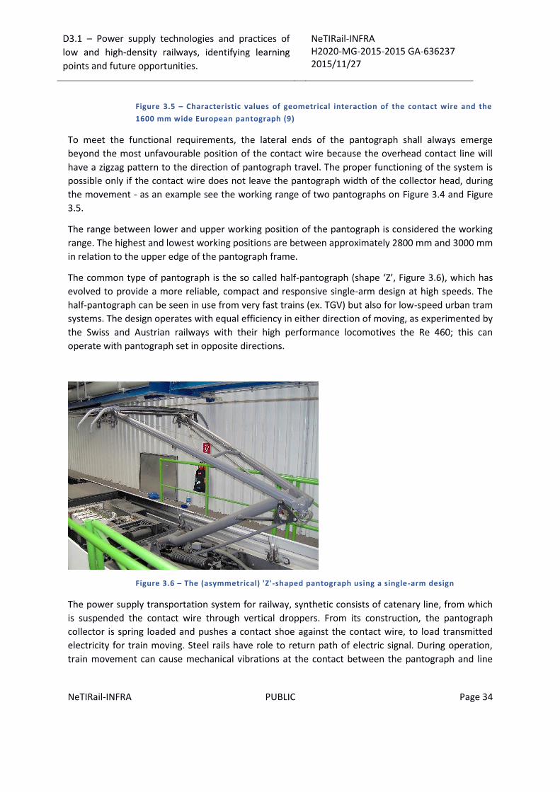
D3.1 – Power supply technologies and practices of
low and high-density railways, identifying learning
points and future opportunities.
NeTIRail-INFRA H2020-MG-2015-2015 GA-636237 2015/11/27
NeTIRail-INFRA PUBLIC Page 34
Figure 3.5 – Characteristic values of geometrical interaction of the contact wire and the
1600 mm wide European pantograph (9)
To meet the functional requirements, the lateral ends of the pantograph shall always emerge
beyond the most unfavourable position of the contact wire because the overhead contact line will
have a zigzag pattern to the direction of pantograph travel. The proper functioning of the system is
possible only if the contact wire does not leave the pantograph width of the collector head, during
the movement - as an example see the working range of two pantographs on Figure 3.4 and Figure
3.5.
The range between lower and upper working position of the pantograph is considered the working
range. The highest and lowest working positions are between approximately 2800 mm and 3000 mm
in relation to the upper edge of the pantograph frame.
The common type of pantograph is the so called half-pantograph (shape ‘Z’, Figure 3.6), which has
evolved to provide a more reliable, compact and responsive single-arm design at high speeds. The
half-pantograph can be seen in use from very fast trains (ex. TGV) but also for low-speed urban tram
systems. The design operates with equal efficiency in either direction of moving, as experimented by
the Swiss and Austrian railways with their high performance locomotives the Re 460; this can
operate with pantograph set in opposite directions.
Figure 3.6 – The (asymmetrical) 'Z'-shaped pantograph using a single-arm design
The power supply transportation system for railway, synthetic consists of catenary line, from which
is suspended the contact wire through vertical droppers. From its construction, the pantograph
collector is spring loaded and pushes a contact shoe against the contact wire, to load transmitted
electricity for train moving. Steel rails have role to return path of electric signal. During operation,
train movement can cause mechanical vibrations at the contact between the pantograph and line

D3.1 – Power supply technologies and practices of
low and high-density railways, identifying learning
points and future opportunities.
NeTIRail-INFRA H2020-MG-2015-2015 GA-636237 2015/11/27
NeTIRail-INFRA PUBLIC Page 35
and produce large variations of the electrical flow power and, in some situations, interruption for
short time of electric contact; these cases lead to strong electromagnetic fields disturbing.
The pantograph is a successor technology for trolley poles which have been used extensively in early
versions of the tram; for trolleybuses are still used. The main reasons are greater freedom of
movement for the two separate arms but also necessity for the current return paths, that trolleybus
cannot provide through the wheels. In some cases, ex. Toronto trolley pole systems are still used for
tram cars, because freedom of movement into a network with sharp turns.
Pantographs in contact with overhead wires are the most used solution for current collection on
modern electric trains because they allow the use of higher voltages, even if it is more expensive and
fragile than a third rail system.
Pantographs are driven by compressed air supplied from the locomotive brake system. This system
is used to raise the current collector and pressing on the contact line or when it is lowered for
interrupting electrical contact. As a precaution for the pressure loss, when is not active, the arm is
held in the lowered position through a mechanical fastening system.
Pantographs are designed as a single or a double arm. Double arm pantographs (see Figure 3.7) are
heavier and require more power to be raised and lowered; the advantage is that to be more fault
tolerant. For example, for increasing reliability of the contact with overhead line, in the North-east
Corridor Branch (New York City – Trenton, NJ), the single arm pantographs was replaced with a more
reliable dual arm model Also, on railways of the former URSS, the most widely used pantographs are
a double arm. With time, single arm variant is replacing the systems with two arms due to
technological improvements.
Figure 3.7 – Symmetrical, diamond shaped pantographs of the Swiss cogwheel locomotive
of the Schynige Platte railway
As comparative situations, in Table 3.1 are presented characteristics of traction power supply
systems in Europe.

D3.1 – Power supply technologies and practices of
low and high-density railways, identifying learning
points and future opportunities.
NeTIRail-INFRA H2020-MG-2015-2015 GA-636237 2015/11/27
NeTIRail-INFRA PUBLIC Page 36
Characteristics
Country Type of
power supply
Stagger
mm
Pantograph width
mm
France
High-speed lines AC 25kV/ 50Hz 200 1450 or 1600
Conventional lines DC 1.5kV 200 1600 or 1950
Germany
High-speed lines AC 15kV/ 16.7Hz 300 1600 or 1950
Conventional lines AC 15kV/ 16.7Hz 400 1950
Austria
Conventional lines AC 15kV/ 16.7Hz 400 1950
Denmark
Conventional lines (2) AC 25kV/ 50Hz 275 1950
Spain
High-speed lines AC 25kV/ 50Hz 300 or 200 1 950 and 1 600
Conventional lines DC 3kV 200 1950
Netherlands
High-speed lines AC 25 kV/ 50Hz 200 1600
Conventional lines DC 1.5 kV 350 1600 or 1950
Portugal
Conventional lines AC 25 kV/ 50Hz 200 1450 or 1600
Italy
High-speed lines DC 3 kV or AC 25 kV/ 50 Hz 300 1600
Conventional lines DC 3 kV 300 1600
Belgium
High-speed lines AC 25 kV/ 50Hz 200 1450 or 1600
Conventional lines DC 3 kV 350 1950
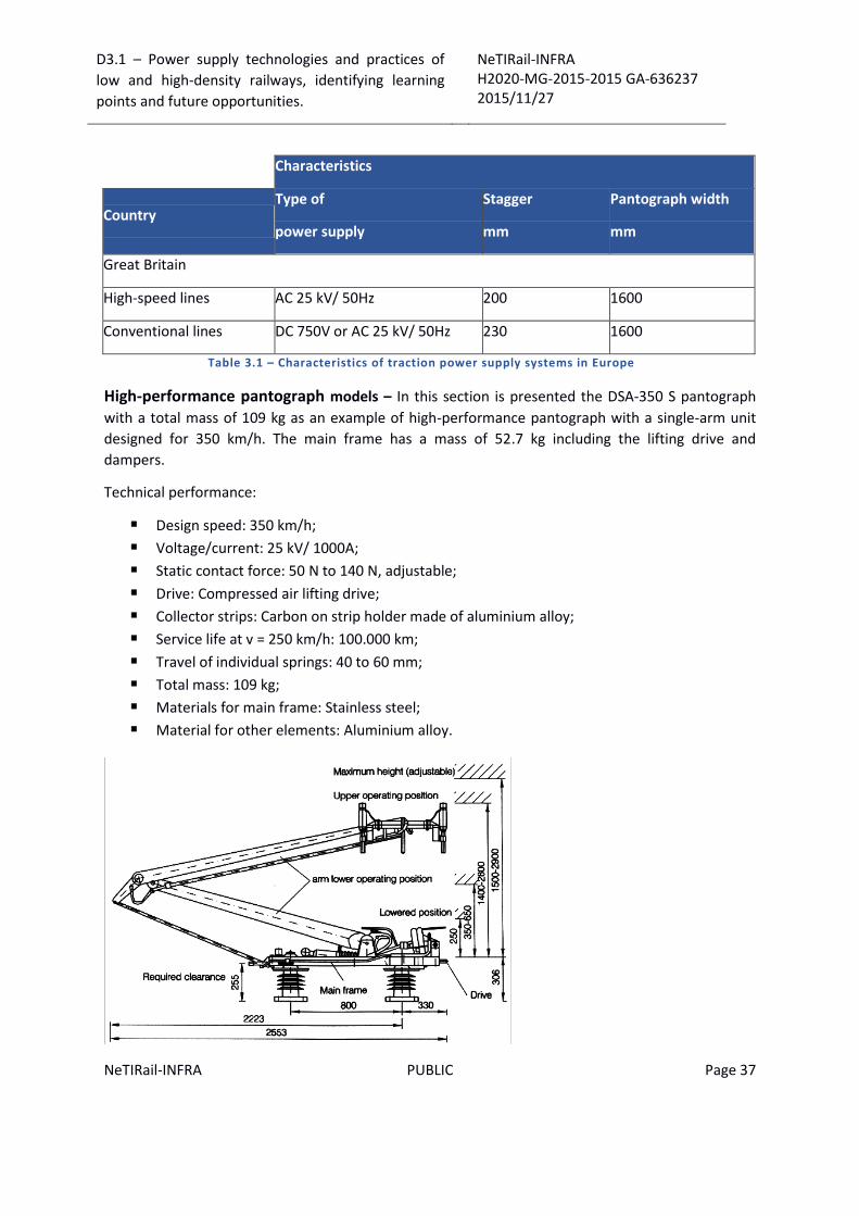
D3.1 – Power supply technologies and practices of
low and high-density railways, identifying learning
points and future opportunities.
NeTIRail-INFRA H2020-MG-2015-2015 GA-636237 2015/11/27
NeTIRail-INFRA PUBLIC Page 37
Characteristics
Country Type of
power supply
Stagger
mm
Pantograph width
mm
Great Britain
High-speed lines AC 25 kV/ 50Hz 200 1600
Conventional lines DC 750V or AC 25 kV/ 50Hz 230 1600
Table 3.1 – Characteristics of traction power supply systems in Europe
High-performance pantograph models – In this section is presented the DSA-350 S pantograph
with a total mass of 109 kg as an example of high-performance pantograph with a single-arm unit
designed for 350 km/h. The main frame has a mass of 52.7 kg including the lifting drive and
dampers.
Technical performance:
Design speed: 350 km/h;
Voltage/current: 25 kV/ 1000A;
Static contact force: 50 N to 140 N, adjustable;
Drive: Compressed air lifting drive;
Collector strips: Carbon on strip holder made of aluminium alloy;
Service life at v = 250 km/h: 100.000 km;
Travel of individual springs: 40 to 60 mm;
Total mass: 109 kg;
Materials for main frame: Stainless steel;
Material for other elements: Aluminium alloy.
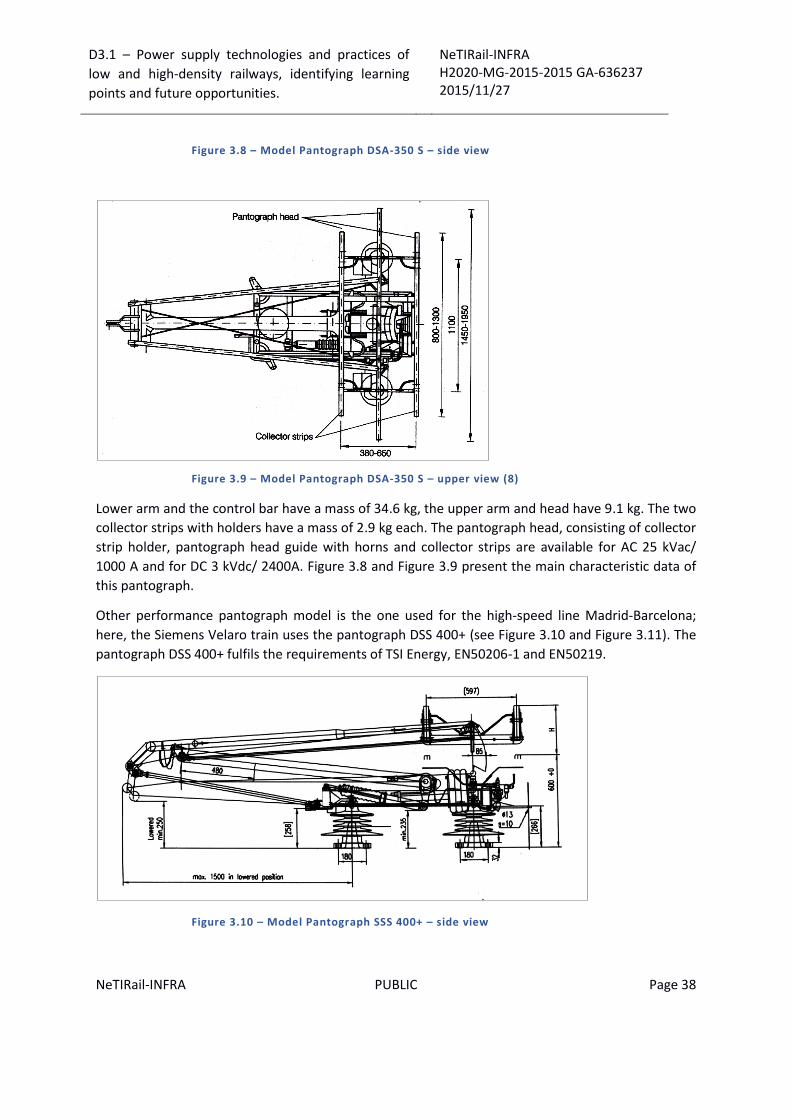
D3.1 – Power supply technologies and practices of
low and high-density railways, identifying learning
points and future opportunities.
NeTIRail-INFRA H2020-MG-2015-2015 GA-636237 2015/11/27
NeTIRail-INFRA PUBLIC Page 38
Figure 3.8 – Model Pantograph DSA-350 S – side view
Figure 3.9 – Model Pantograph DSA-350 S – upper view (8)
Lower arm and the control bar have a mass of 34.6 kg, the upper arm and head have 9.1 kg. The two
collector strips with holders have a mass of 2.9 kg each. The pantograph head, consisting of collector
strip holder, pantograph head guide with horns and collector strips are available for AC 25 kVac/
1000 A and for DC 3 kVdc/ 2400A. Figure 3.8 and Figure 3.9 present the main characteristic data of
this pantograph.
Other performance pantograph model is the one used for the high-speed line Madrid-Barcelona;
here, the Siemens Velaro train uses the pantograph DSS 400+ (see Figure 3.10 and Figure 3.11). The
pantograph DSS 400+ fulfils the requirements of TSI Energy, EN50206-1 and EN50219.
Figure 3.10 – Model Pantograph SSS 400+ – side view

D3.1 – Power supply technologies and practices of
low and high-density railways, identifying learning
points and future opportunities.
NeTIRail-INFRA H2020-MG-2015-2015 GA-636237 2015/11/27
NeTIRail-INFRA PUBLIC Page 39
Figure 3.11 – Model Pantograph SSS 400+ – upper view (9)
Technical performance:
Design speed: 350 km/h;
Voltage/current: 25 kVac/ 1000 A;
Static contact force: 50 N to 140 N, adjustable;
Drive: Compressed air lifting drive;
Collector strips: Carbon on strip holder made of aluminium alloy;
Service life at v = 350 km/h: 100.000 km;
Materials of main frame: Stainless steel;
Materials of other elements: Aluminium alloy.
Overhead pantographs can be used as alternatives to third rails, even where third rail is dedicated,
because third rails present at least two disadvantages: many crossings make impractically the third
rail solution and third rails can collect ice in certain winter weather conditions. As other example, the
Metro system of Barcelona in Spain, uses overhead wiring and pantographs. The Oslo metro Line 1
changed from third rail to overhead line power due to the many level crossings, where it is very
difficult to install a third rail.
3.3.4 Overhead tensioning lines
In electrification railways networks, the contact lines should be at relative constant mechanical
tension to prevent pantograph oscillations in the electrical lines. Furthermore, the wave generated
by trains at high speed must go faster than the train to prevent the generation of standing waves
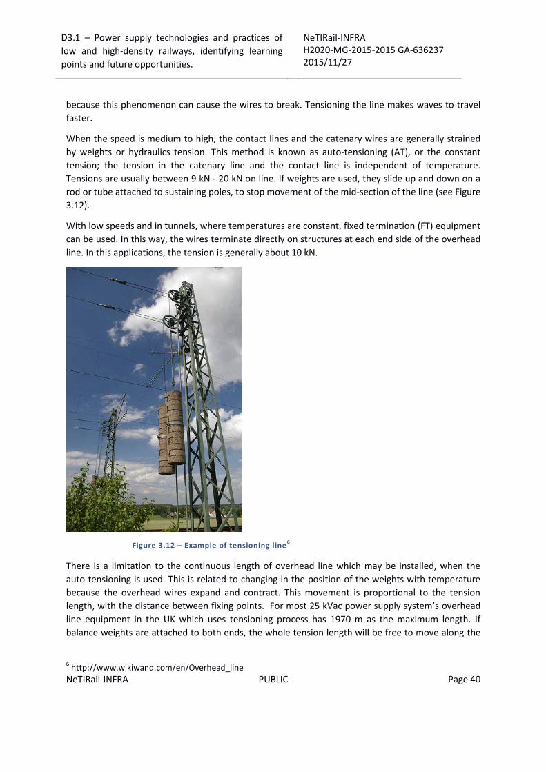
D3.1 – Power supply technologies and practices of
low and high-density railways, identifying learning
points and future opportunities.
NeTIRail-INFRA H2020-MG-2015-2015 GA-636237 2015/11/27
NeTIRail-INFRA PUBLIC Page 40
because this phenomenon can cause the wires to break. Tensioning the line makes waves to travel
faster.
When the speed is medium to high, the contact lines and the catenary wires are generally strained
by weights or hydraulics tension. This method is known as auto-tensioning (AT), or the constant
tension; the tension in the catenary line and the contact line is independent of temperature.
Tensions are usually between 9 kN - 20 kN on line. If weights are used, they slide up and down on a
rod or tube attached to sustaining poles, to stop movement of the mid-section of the line (see Figure
3.12).
With low speeds and in tunnels, where temperatures are constant, fixed termination (FT) equipment
can be used. In this way, the wires terminate directly on structures at each end side of the overhead
line. In this applications, the tension is generally about 10 kN.
Figure 3.12 – Example of tensioning line6
There is a limitation to the continuous length of overhead line which may be installed, when the
auto tensioning is used. This is related to changing in the position of the weights with temperature
because the overhead wires expand and contract. This movement is proportional to the tension
length, with the distance between fixing points. For most 25 kVac power supply system’s overhead
line equipment in the UK which uses tensioning process has 1970 m as the maximum length. If
balance weights are attached to both ends, the whole tension length will be free to move along the
6 http://www.wikiwand.com/en/Overhead_line
D3.1 – Power supply technologies and practices of
low and high-density railways, identifying learning
points and future opportunities.
NeTIRail-INFRA H2020-MG-2015-2015 GA-636237 2015/11/27
NeTIRail-INFRA PUBLIC Page 41
track. To avoid this issue, a midpoint anchor (MPA), close to the centre of the line tensioning length,
restricts the movement of the wire by fixing it. Thus, the contact wire can move only within the
constraints of the MPA.
MPAs are anchored in many cases to the typical vertical catenary poles or portal catenary supports.
So, a tension length can be seen as a fixed centre point, with two half wires tension lengths,
expanding and contracting with temperature.
Most systems from overhead tensioning line category, include a brake suspended to stop threads to
gather at every tensioning side or fall on the track when the mechanical tension is lost or the wire is
broken for any other reason. German systems typically use a single high tension pulley with a
serrated edge mounted on an articulated arm to the mast. In this case the downward pull of the
weights, and the reactive upward pull of the tensioned wires, lifts the pulley so its teeth are well
clear of a stop on the mast. The pulley can move and turn freely while the weights move up or down
as the wires contract or expand. If a contact wire or catenary wire break or tension is lost from other
causes, the pulley back falls, toward the mast, and one of its teeth will block the system and will
provide the stop of the falling wires. This stops the wheel rotation, limits the damage and keeps
intact the not damaged section of the contact and catenary wire, until it can be repaired.
In this case, the weight of the tensioning system is balanced with tension wires and do not touch the
gear of lock wheel. If the contact wire is broken or nominal tension is lost from different reasons,
tensioner wheel falls back to supporting mast and one of his teeth will block unwanted rotation. This
lock limits damage and keep intact a portion of the wire until it can be repaired.
3.3.5 Electric multiple unit
An electric multiple unit or EMU is a multiple unit train consisting of self-propelled carriages, using
electricity as the motive power. An EMU requires no separate locomotive because the electric
traction motors are incorporated within one or more of the carriages.
Most EMUs are used for passenger trains, but some have been built or converted for specialised
non-passenger roles, such as carrying mail or luggage, or in departmental and maintenance use, for
example as de-icing trains.
EMUs are used frequently on commuter and suburban rail networks, due to their fast acceleration
and low level of pollution. Being quieter than DMUs, EMUs can operate later at night and more
frequently without disturbing residents living close to the railway section. Also, very importantly, the
tunnel design will be economically acceptable when EMU trains are considered, because there is no
need to make supplementary facilities for diesel fumes ventilation.
The railway cars that form a complete EMU set can usually be separated by function into four types:
power car, motor car, driving car, and trailer car. But in generally, each of them can have more than
one function, ex.: motor-driving car has also equipment for power-driving car.
Power car - carries the necessary equipment to draw power from the electrified infrastructure, such
as pickup shoes for third rail systems and pantographs for overhead systems, and transformers.
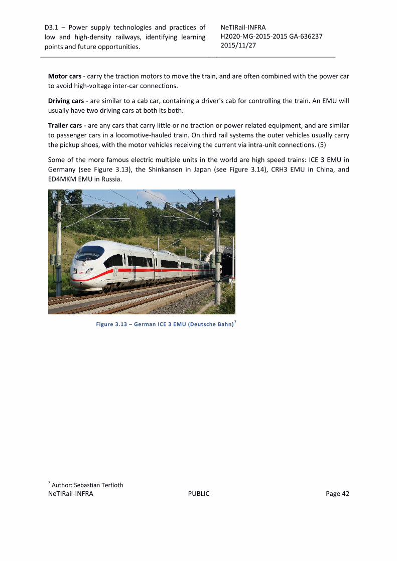
D3.1 – Power supply technologies and practices of
low and high-density railways, identifying learning
points and future opportunities.
NeTIRail-INFRA H2020-MG-2015-2015 GA-636237 2015/11/27
NeTIRail-INFRA PUBLIC Page 42
Motor cars - carry the traction motors to move the train, and are often combined with the power car
to avoid high-voltage inter-car connections.
Driving cars - are similar to a cab car, containing a driver's cab for controlling the train. An EMU will
usually have two driving cars at both its both.
Trailer cars - are any cars that carry little or no traction or power related equipment, and are similar
to passenger cars in a locomotive-hauled train. On third rail systems the outer vehicles usually carry
the pickup shoes, with the motor vehicles receiving the current via intra-unit connections. (5)
Some of the more famous electric multiple units in the world are high speed trains: ICE 3 EMU in
Germany (see Figure 3.13), the Shinkansen in Japan (see Figure 3.14), CRH3 EMU in China, and
ED4MKM EMU in Russia.
Figure 3.13 – German ICE 3 EMU (Deutsche Bahn)7
7 Author: Sebastian Terfloth

D3.1 – Power supply technologies and practices of
low and high-density railways, identifying learning
points and future opportunities.
NeTIRail-INFRA H2020-MG-2015-2015 GA-636237 2015/11/27
NeTIRail-INFRA PUBLIC Page 43
Figure 3.14 – Japanese JR West Shinkansen Type 500 EMU
3.3.6 Neutral sections
Neutral sections usually represent an earthed section of wire which is separated from the current
feeding wires, on either side, by insulating material, e.g. ceramic beads. This is designed so that the
pantograph will run smoothly between the two electrified sections.
Electric isolations are necessary to subdivide the contact line installation into different electrical
sections or circuits. Dependent upon the operating speed, sectioning devices or section insulators
are used for this purpose in stations and at speeds up to 160 km/h. On main line tracks and at
speeds above 160 km/h, special insulated overlaps are provided in the overhead contact line.
Neutral sections are designed to fulfil the following:
Help maintenance process, allowing inspection and repairing when is needed, for sections of
the overhead line without to turn off the entire system – this is case of section break;
Isolates power supply sections from different power supply stations, avoiding mixing power
supply characteristics; prevent the risk out of phase supplies mixing – this is case of phase
break.
Section insulator - For transition through break section, the locomotive's pantograph should be in
continuous contact with the wire. This is accomplished by two contact wires running in parallel to
each other over a specified length: a new one dropping down and the old one rising up until the
pantograph smoothly transfers from one to the next section. The two wires are not in electrical
contact even if the pantograph is briefly in contact with both wires. In normal service, the two
sections are electrically connected to different substations with different electrical parameters.
The pantograph may have problems to run through a section break when one side is de-energized.
The locomotive would then become trapped, but most dangerously, if it passes the section break,
the pantograph will make short circuit with the two catenary lines together. If the opposite line is
de-energized, this voltage transient may supply this line. If the line is under maintenance, personnel

D3.1 – Power supply technologies and practices of
low and high-density railways, identifying learning
points and future opportunities.
NeTIRail-INFRA H2020-MG-2015-2015 GA-636237 2015/11/27
NeTIRail-INFRA PUBLIC Page 44
injury may occur as the contact line and catenary are suddenly energized. Other negative effect is
the arc generated across the pantograph which will cause damage to the pantograph and/or the
catenary insulator.
In the Figure 3.15 is showed an example of short neutral section with insulation.
Figure 3.15 – Neutral section insulator
Phase separation – On a larger electrified railway it is necessary to power different section of track
from different power grids, the synchronisation of the phases cannot be guaranteed, even if they are
designed for the same phase.
Another situation is when the sections are powered with different voltages or frequencies. Even if
equipment to synchronize these sections electrically is used, on a normal basis but events may cause
de-synchronisation. It is recommended not to connect two grids even designed to be synchronised
but supplied from different sources. A normal section break is insufficient to guard against this, since
the pantograph briefly connects both sections. For this situation a phase separation break technique
is used. This means two section breaks back-to-back; so, existing a short section of overhead line
that are not connected to any power supplied section. The locomotive will pass from one grid to
other not disturbing any one section; this separation will ensure that the two grids cannot be
connected to each other.
Neutral sections as phase separation are necessary in the following situations:
Areas with different energy supply systems, e.g. between DC 3 kV and AC 25 kVac/ 50 Hz or
AC 15 kVac/ 16.7 Hz;
Feeder sections with different phases, e.g. feeder sections in AC 25 kV networks, which are
supplied from different phases of the national public power grid. From this situation this
neutral section design known as phase separation;
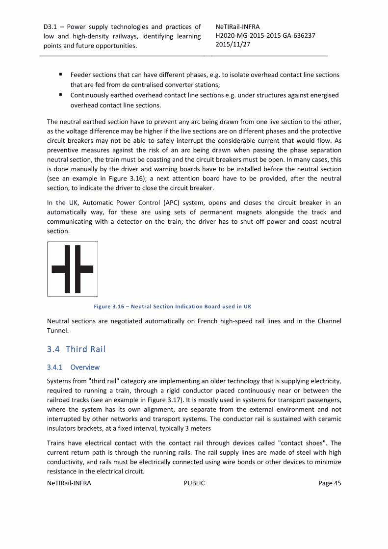
D3.1 – Power supply technologies and practices of
low and high-density railways, identifying learning
points and future opportunities.
NeTIRail-INFRA H2020-MG-2015-2015 GA-636237 2015/11/27
NeTIRail-INFRA PUBLIC Page 45
Feeder sections that can have different phases, e.g. to isolate overhead contact line sections
that are fed from de centralised converter stations;
Continuously earthed overhead contact line sections e.g. under structures against energised
overhead contact line sections.
The neutral earthed section have to prevent any arc being drawn from one live section to the other,
as the voltage difference may be higher if the live sections are on different phases and the protective
circuit breakers may not be able to safely interrupt the considerable current that would flow. As
preventive measures against the risk of an arc being drawn when passing the phase separation
neutral section, the train must be coasting and the circuit breakers must be open. In many cases, this
is done manually by the driver and warning boards have to be installed before the neutral section
(see an example in Figure 3.16); a next attention board have to be provided, after the neutral
section, to indicate the driver to close the circuit breaker.
In the UK, Automatic Power Control (APC) system, opens and closes the circuit breaker in an
automatically way, for these are using sets of permanent magnets alongside the track and
communicating with a detector on the train; the driver has to shut off power and coast neutral
section.
Figure 3.16 – Neutral Section Indication Board used in UK
Neutral sections are negotiated automatically on French high-speed rail lines and in the Channel
Tunnel.
3.4 Third Rail
3.4.1 Overview
Systems from "third rail" category are implementing an older technology that is supplying electricity,
required to running a train, through a rigid conductor placed continuously near or between the
railroad tracks (see an example in Figure 3.17). It is mostly used in systems for transport passengers,
where the system has its own alignment, are separate from the external environment and not
interrupted by other networks and transport systems. The conductor rail is sustained with ceramic
insulators brackets, at a fixed interval, typically 3 meters
Trains have electrical contact with the contact rail through devices called "contact shoes". The
current return path is through the running rails. The rail supply lines are made of steel with high
conductivity, and rails must be electrically connected using wire bonds or other devices to minimize
resistance in the electrical circuit.

D3.1 – Power supply technologies and practices of
low and high-density railways, identifying learning
points and future opportunities.
NeTIRail-INFRA H2020-MG-2015-2015 GA-636237 2015/11/27
NeTIRail-INFRA PUBLIC Page 46
When at level crossings and crossovers, the conductor rails have to be interrupted; ramps are
provided at the ends of the sections to give a smooth transition for the train shoes.
Figure 3.17 – British Class 442 third rail electric multiple unit in Dorset; this is the fastest
class of third rail EMU in the world, reaching 172 km/h
The contact point between train shoe and the third rail are provided in multiple variants; some of
these use top contact but experience has determined that the variants side or bottom contacts are
betters. In these situations, conductor rail could be covered and protecting track workers and
pedestrians from accidental contact, also protecting the contact conductor from snow and leaf fall.
3.4.2 Technical aspects
Third rail systems provide electric power to a railway train, through a semi-continuous rigid
conductor placed alongside or between the rails of a railway track, are used in a mass transit or rapid
transit system and are always supplied from direct current electricity
Most railway power supply systems use overhead contact lines, but the third rail can be an efficient
solution for voltages lower than 1200 V. The third rail is more compact and a better solution in small
diameter tunnels; this is an important condition in the subway systems.
Third rail systems are designed to use one of the next variants related to contact position: top
contact, side contact or bottom contact. The top contact is considered less safe while side-contact
and bottom-contact can be provided with safety shields. Also, top-contact for third rails are
vulnerable to interruptions caused by fallen leaves, ice and snow.
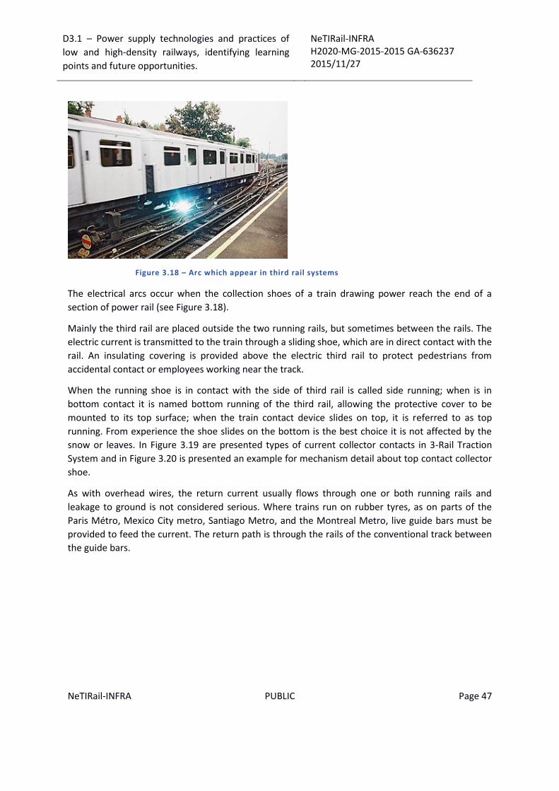
D3.1 – Power supply technologies and practices of
low and high-density railways, identifying learning
points and future opportunities.
NeTIRail-INFRA H2020-MG-2015-2015 GA-636237 2015/11/27
NeTIRail-INFRA PUBLIC Page 47
Figure 3.18 – Arc which appear in third rail systems
The electrical arcs occur when the collection shoes of a train drawing power reach the end of a
section of power rail (see Figure 3.18).
Mainly the third rail are placed outside the two running rails, but sometimes between the rails. The
electric current is transmitted to the train through a sliding shoe, which are in direct contact with the
rail. An insulating covering is provided above the electric third rail to protect pedestrians from
accidental contact or employees working near the track.
When the running shoe is in contact with the side of third rail is called side running; when is in
bottom contact it is named bottom running of the third rail, allowing the protective cover to be
mounted to its top surface; when the train contact device slides on top, it is referred to as top
running. From experience the shoe slides on the bottom is the best choice it is not affected by the
snow or leaves. In Figure 3.19 are presented types of current collector contacts in 3-Rail Traction
System and in Figure 3.20 is presented an example for mechanism detail about top contact collector
shoe.
As with overhead wires, the return current usually flows through one or both running rails and
leakage to ground is not considered serious. Where trains run on rubber tyres, as on parts of the
Paris Métro, Mexico City metro, Santiago Metro, and the Montreal Metro, live guide bars must be
provided to feed the current. The return path is through the rails of the conventional track between
the guide bars.

D3.1 – Power supply technologies and practices of
low and high-density railways, identifying learning
points and future opportunities.
NeTIRail-INFRA H2020-MG-2015-2015 GA-636237 2015/11/27
NeTIRail-INFRA PUBLIC Page 48
Figure 3.19 – Types of current collector contacts in 3-Rail Traction System8
Figure 3.20 – Top contact collector shoe – London Underground – Central Line9
Another version of the design shows a third rail outside the running rails, with role of current feed
and a fourth rail used for current return and it is placed half way between the running rails; this type
is used by a few steel-wheel systems. The London Underground is the largest of these. The third rail
could be considered an alternative to overhead lines, but in particular situations.
The third rail system uses a “contact collector shoe" to collect the current on the train based on a
top contact third rail system.
8 http://www.railway-technical.com/etracp.shtml
9 http://www.railway-technical.com/etracp.shtml

D3.1 – Power supply technologies and practices of
low and high-density railways, identifying learning
points and future opportunities.
NeTIRail-INFRA H2020-MG-2015-2015 GA-636237 2015/11/27
NeTIRail-INFRA PUBLIC Page 49
Recently, mechanical or pneumatic systems have been devised to make it possible to lift shoes from
inside the train remotely from the driving cab. Side and bottom contact shoes are spring loaded to
provide the necessary contact force. The bottom contact shoe, as example, is used on a German
metro line.
Figure 3.21 – Third rail contact shoe10
The third rail must be broken at junctions to allow the continuity of running rails. These third rail
breaks, or "gaps", as they are called, can lead to loss of power on the train. Current rail gaps are also
provided where the substations feed the line. Each track is fed in each direction towards the next
substation and this allows over supply and provides continuity if one substation fails. These
substation gaps are usually marked by a sign or a light which indicates the current is on/off in the
section ahead. A train must stop before entering the dead section. Today there are more
sophisticated systems in use which link the traction current status to the signalling so that a train will
not be allowed to proceed onto a dead section.
The choice of AC or DC power transmission system along the line is important. AC is for long distance
and DC is for short distance. AC is easier to transmit over long distances being an ideal medium for
electric railways. The problems of converting it on the train to run DC motors restricted its
widespread adoption until the 1960s. DC was the preferred option for shorter lines, urban systems
and tramways and was used on a number of main line railway systems, and still is in some parts of
continental Europe The smaller size of urban operations needed trains usually lighter and less
power, a heavier transmission medium, a third rail or a thick wire, to carry the power and it lost a
fair amount of voltage as the distance between supplies connections increased.
The corrosion is always a factor to be considered in electric supply systems, particularly DC systems.
The tendency of return currents to wander away from the running rails into the ground can set up
10 Author: Daniel Schwen

D3.1 – Power supply technologies and practices of
low and high-density railways, identifying learning
points and future opportunities.
NeTIRail-INFRA H2020-MG-2015-2015 GA-636237 2015/11/27
NeTIRail-INFRA PUBLIC Page 50
electrolysis with water pipes and similar metallic. Underground railways adopted a fully insulated
DC system with a separate negative return rail as well as a positive rail – the four rail system.
3.4.3 Advantages and disadvantages
Third rail in railway systems is limited in use due to the small tensions can run. Limitation due to
relatively small voltages will limit the size and speed of trains and comfort levels; for example, the
amount of air-conditioning that the trains can offer. This could be a reason favouring overhead wires
and high voltage alternative current, even for urban systems. From testing and experiments, the top
speed of trains on third rail systems is up to 100 mph; above that speed, the contact between the
shoe and the rail cannot be maintained enough to be stable.
Obviously, traction system based on electricity supply of locomotives, as a principle, is more
advantageous in terms of operational costs but also more effective in terms of service quality
provided than diesel or steam locomotives. Diesel and steam car units produce energy locally while
traction power supply variant produce the same traction energy in remote fixed substations, and
send it through the overhead lines to traction units.
For electric power supply systems, taking in account the costs, mainly initial investment cost, third-
rail systems are advantageous to install and operate, compared to overhead wire contact systems,
as no structures for carrying the overhead contact wires are required, and there is no need to
reconstruct over bridges to provide clearances. Third rail system type has much less visual intrusion
for environment.
The main disadvantage of third rail systems is that they present the hazard of electric shock because
higher system voltages; for this reason, all voltages used, above 1500 V are not considered safe.
When voltage is reduced, to compensate, the current into circuit has to be increased; that results in
considerable power loss in the system and relatively closely substations for electricity supply are
needed.
An electric power supply system for railway could become extremely dangerous for a person that fall
into the tracks. This, however, can be avoided using platform screen doors. Also the risk could be
easy minimized by placing the conductor rail on one side of the track, away from the platform.
In addition, third rail systems must be fully separated from the route of pedestrians. If it is operated
at the same grade, mechanisms that stop people from walking onto the tracks at grade crossings
must be implemented. Due to the mechanical technology used at contact point between third rail
and current collector the speed for this type of traction is generally lower than overhead line
systems. A speed of 160 km/h is considered the highest limit of practical third rail operation. The
world speed record for a third rail train is 174 km/h reached on 11 April 1988 by a British Class 442
EMU.
Third rail systems using top contact are susceptible to accumulations of snow, and ice formed from
refrozen snow, and this can interrupt operations. Some systems operate with dedicated de-icing
trains to deposit an oily or glycol based anti-icing fluid on the conductor rail to prevent the
accumulation of ice.

D3.1 – Power supply technologies and practices of
low and high-density railways, identifying learning
points and future opportunities.
NeTIRail-INFRA H2020-MG-2015-2015 GA-636237 2015/11/27
NeTIRail-INFRA PUBLIC Page 51
A special situation happens at level crossings and railroad crossings. In this section it is possible for a
train to stop in a position in which the running shoe is not in contact with the rail and no traction
power is available. The train is said to be "gapped". In these circumstances another train is brought
back to push the blocked train over power rail interrupted section until one of his shoes gets back in
contact with the third line. One solution to prevent such situations is that way of hauling trains to be
equipped with several contact shoes at distance one from other, larger than maximum gap.
Electrical systems for traction using third rail are not obsolete; there are countries - Japan, South
Korea, India, Spain, etc. accepting and adopting in particular cases new third rail systems building,
especially where small capacity people movements exist. The type of railways where third rail is very
rarely used in new systems, is regional and long distance rail, which require higher speeds and higher
voltages.
3.5 Fourth rail
There are few networks that use a four rail system, one of them being London Underground in
England. The additional rail transports the electric return current; on the third rail and overhead
networks this function is provided by the running rails. As an example, the London Underground
uses a top-contact third rail, energized at +420Vdc and a top-contact fourth rail is located between
the running rails at a negative voltage of −210Vdc so that voltages provide a traction voltage of 630
Vdc. In the figure below the unprotected third rail is at the right of the track and the fourth rail at
the centre.
Figure 3.22 – Fourth rail and third rail11
The main advantage of the four-rail system is that the running rail carries no current and does not
involve problems caused by return currents. Returning current can cause electrolytic damage and
11 http://www.wikiwand.com/en/Railway_electrification_system
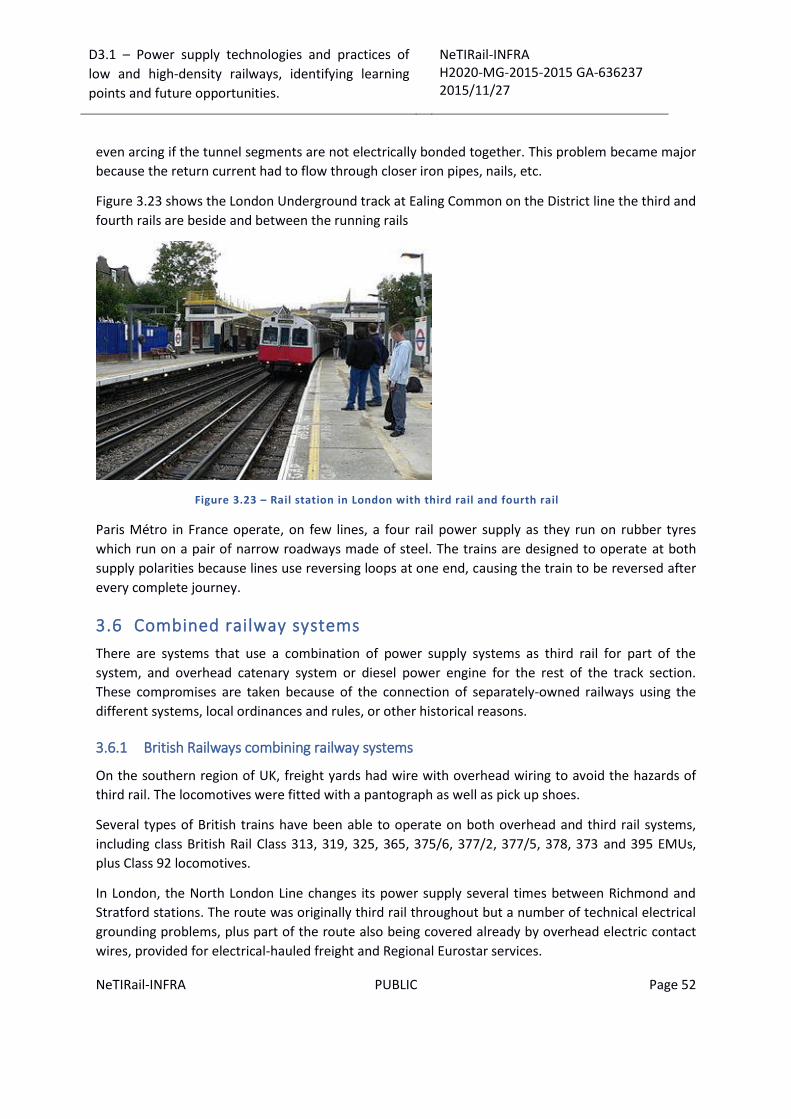
D3.1 – Power supply technologies and practices of
low and high-density railways, identifying learning
points and future opportunities.
NeTIRail-INFRA H2020-MG-2015-2015 GA-636237 2015/11/27
NeTIRail-INFRA PUBLIC Page 52
even arcing if the tunnel segments are not electrically bonded together. This problem became major
because the return current had to flow through closer iron pipes, nails, etc.
Figure 3.23 shows the London Underground track at Ealing Common on the District line the third and
fourth rails are beside and between the running rails
Figure 3.23 – Rail station in London with third rail and fourth rail
Paris Métro in France operate, on few lines, a four rail power supply as they run on rubber tyres
which run on a pair of narrow roadways made of steel. The trains are designed to operate at both
supply polarities because lines use reversing loops at one end, causing the train to be reversed after
every complete journey.
3.6 Combined railway systems
There are systems that use a combination of power supply systems as third rail for part of the
system, and overhead catenary system or diesel power engine for the rest of the track section.
These compromises are taken because of the connection of separately-owned railways using the
different systems, local ordinances and rules, or other historical reasons.
3.6.1 British Railways combining railway systems
On the southern region of UK, freight yards had wire with overhead wiring to avoid the hazards of
third rail. The locomotives were fitted with a pantograph as well as pick up shoes.
Several types of British trains have been able to operate on both overhead and third rail systems,
including class British Rail Class 313, 319, 325, 365, 375/6, 377/2, 377/5, 378, 373 and 395 EMUs,
plus Class 92 locomotives.
In London, the North London Line changes its power supply several times between Richmond and
Stratford stations. The route was originally third rail throughout but a number of technical electrical
grounding problems, plus part of the route also being covered already by overhead electric contact
wires, provided for electrical-hauled freight and Regional Eurostar services.

D3.1 – Power supply technologies and practices of
low and high-density railways, identifying learning
points and future opportunities.
NeTIRail-INFRA H2020-MG-2015-2015 GA-636237 2015/11/27
NeTIRail-INFRA PUBLIC Page 53
The cross-city Thameslink service runs on the Southern Region third rail network from Farringdon
station southwards and on overhead line northwards from Farringdon to Bedford. The changeover is
made whilst stationary at Farringdon.
On the Moorgate to Hertford and Welwyn suburban service routes, the East Coast Main Line
sections are 25 kVac, with a changeover to third rail made at Drayton Park railway station. Third rail
is still used in the tunnel-section of the route, because the size of the tunnels, leading to Moorgate
station, was too small to allow overhead electrification. (5)
The British Rail Class 373 or TGV TMST train is an electric multiple unit that operates Eurostar's inter-
city high-speed rail service between England, France and Belgium via the Channel Tunnel and uses
overhead collector at 25 kVas for most of its journey, with sections of 3 kVdc or 1.5 kVdc on the
Continent. The first models (the Class 373 units) were additionally fitted with 750 Vdc collection
shoes so that they were designed for drive in London via the suburban lines for commuter. A switch
between third rail and overhead collection was performed whilst running at speed, initially at
Continental Junction near Folkstone, and later on at Fawkham Junction after the opening of the first
section of the Channel Tunnel rail link. The dual system caused some problems when drivers forgot
to switch between modes. Failure to retract the shoes when entering France caused severe damage
to track side equipment; for this reason, SNCF installed a concrete block at the Calais at end of the
Channel Tunnel to break off the 3rd rail shoe if it had not been retracted. Other case was an accident
occurred in the UK when a Eurostar driver failed to retract the pantograph before entering the third
rail system, damaging a signal gantry and the pantograph.
On 14 November 2007, Eurostar passenger operations were transferred to St. Pancras railway
station and maintenance operations to Temple Mills depot deprecating the requirement for the 750
Vdc, third rail power collecting equipment and leading to its removal from the fleet.
UK South-eastern railway starts to operate internal services from 2009, on High Speed 1 from St.
Pancras using Class 395 EMU. These services operate on the high speed line after that transferring to
the classic lines to serve north and mid Kent. As a consequence, these trains are dual voltage
enabled, as the majority of the routes over which they operate are third rail electrified.
3.6.2 USA combining railway systems
In New York City, electric trains when leaving Grand Central Terminal on the Metro-North Railroad
must use the third rail and later switch to overhead lines at Pelham when they need to operate out
onto the former New York, New Haven and Hartford Railroad (now Metro North's New Haven Line)
line to Connecticut. The switch is made "on the go" controlled from the engineer's position.
In New York City, where diesel engines can be a health hazard in underground stations like Metro-
North, the Long Island Rail Road and Amtrak use diesel locomotives but also can be electrically
powered by a third rail. This type of locomotive (e.g. P32AC-DM or DM30AC) may transition
between the two modes, during operation. Auxiliary third rail traction type is not as strong as diesel
engine, so when locomotives arrive at the surface, on open air, switch to running with diesel engines
traction, even if third rail system is also available.

D3.1 – Power supply technologies and practices of
low and high-density railways, identifying learning
points and future opportunities.
NeTIRail-INFRA H2020-MG-2015-2015 GA-636237 2015/11/27
NeTIRail-INFRA PUBLIC Page 54
In Manhattan, New York City, and in Washington DC, the local ordinances and rules required
electrified railways to draw current from a third rail and return the current to a fourth rail, both
installed in a continuous vault underneath the street and accessed by means of a collector that
passed through a slot between the running rails. When streetcars on such systems entered territory
where overhead lines were allowed, they stopped over a pit where a man detached the plough
collector and the motorman placed a trolley pole on the overhead.
The Blue Line of Boston's MBTA uses third rail electrification from the start of the line downtown to
Airport, where it switches to overhead catenary for the remainder of the line to Wonderland.
3.6.3 Conversion Strategy
Despite various technical possibilities of operating stock with dual power collecting modes, the best
technical solution is to achieve full compatibility of entire networks. This is the cause of conversions
from third rail to overhead supply (or vice versa).
Three lines from five, of Barcelona Metro network, changed from third rail system to overhead
power supply system. This operation was also done by stages and completed in 2003.
The South London Line of the LBSCR network between Victoria and London Bridge was electrified
with catenary in 1909. The system was later extended to Crystal Palace, Coulsdon North and Sutton.
In the course of mainline third rail electrification in south-east England, the lines were converted by
1929.
The first overhead electric trains appeared on the Hamburg - Altonaer Stadt-und Vorortbahn in
1907. Thirty years later, the main-line railway operator, Deutsche Reichsbahn, influenced by the
success of the third rail Berlin S-Bahn, decided to switch what was now called Hamburg S-Bahn to
third rail.
Highest voltages used:
Hamburg S-Bahn: 1200 V; since 1940.
Manchester - Bury, England: 1200V (side contact).
Culoz–Modane railway, France: 1500 V; 1925–1976.
Guangzhou Metro, Line 4 and Line 5: 1500 V.
Simultaneous using of power supply systems - a railway can be electrified with overhead wire
system and a third rail system on same time; for example, on the Hamburg S-Bahn between 1940
and 1955. A modern example is Birkenwerder Railway Station near Berlin; this section uses third rail
on both sides and simultaneous overhead wire; whole Penn Station complex in New York City is also
electrified with both systems. But, such systems have problems with the electromagnetic
perturbations of the different current supplies types. For this reason, double electrification is usually
avoided.
The border station of Modane on the French-Italian Fréjus railway was electrified at both 1.5 kVdc
using third rail system for French trains and with overhead wires that provide 3 kVdc for Italian
D3.1 – Power supply technologies and practices of
low and high-density railways, identifying learning
points and future opportunities.
NeTIRail-INFRA H2020-MG-2015-2015 GA-636237 2015/11/27
NeTIRail-INFRA PUBLIC Page 55
trains. When the French line was converted to overhead contact line, the voltage of the Italian wires
was dropped to 1,5kVdc and now run in Modane with 1.5 kVdc having half of their nominal power.
3.6.4 New technologies
The introduction of super capacitors has the potential to lower the cost for trains operating on third
rail and overhead wires. Kinetic energy generated while braking is stored in super capacitors on
board the vehicle. This energy is later used when accelerating. This allows the super capacitors to
reduce current draw through the electrical pickup during acceleration, putting less stress on the
electrical grid. From theory and experiments, claimed peak energy reduction is around 30%.
This technology can also be used for diesel electric locomotives, where 25% to 40% reduction in
energy consumption is possible.
Since 2003, Mannheim Stadtbahn in Mannheim, Germany has operated a light-rail vehicle using
electric double-layer super capacitors to store braking energy.
A number of companies are developing electric double-layer super capacitor technology. Siemens
AG is developing mobile energy storage based on double-layer super capacitors; also the Cegelec
Company is developing an electric double-layer capacitor-based as energy storage system.
D3.1 – Power supply technologies and practices of
low and high-density railways, identifying learning
points and future opportunities.
NeTIRail-INFRA H2020-MG-2015-2015 GA-636237 2015/11/27
NeTIRail-INFRA PUBLIC Page 56
4 New trends and technologies in building, develop and operate installations of railway power supply systems
4.1 High performance Overhead Power Supply Systems
Described here are the most representatives and high performance existing overhead contact lines
systems
4.1.1 Overhead contact lines for 3 kVdc
4.1.1.1 DC 3 kV overhead contact line for the Moscow-St. Petersburg line
This line is named “The October Railway” (OEB) and have operating the distance between Moscow
and St. Petersburg on DC 3 kVdc; maximum speed is stated to 200 km/h. This line is one of the most
used tracks in Russia. Two steady-arms guide the contact wires with a spacing of 40 mm and a
suspension insulator attaches the catenary wire to the cantilever, which consists of angle sections.
The cantilevers are mounted predominantly on concrete poles on inter station tracks, which also
support telephone and signalling lines. Pulley-wheel tensioners compensate for temperature
induced wire length changes of both catenary and contact wires. The insulators used also suitable
for 25 kVac operation. OEB also uses portal structures in addition to flexible head-span equipment in
station areas. Concrete poles support the lattice portal and the lower cross-span wire fixes the
contact wire supports at the portals. (9)
4.1.1.2 Direttissima Rome-Florence
The 238 km long high-speed line operated by the Italian State Railway (FS) completed in 1991, the
Direttissima Rome-Florence, is operated at 3 kVdc and a maximum speed of 250 km/h (see Figure
4.1). On the southern section of the line, the contact line system consists of one catenary wire and
two contact wires. Stitch wires are not used in this design. The catenary wire is tensioned at 27.5 kN
and each of the contact wires at 15 kN. Pulley-wheel tensioners with two pulleys compensate for
temperature induced wire length changes to both catenary and contact wires in this section. The
contact line system on the northern part of the high-speed line consists of two copper contact wires
Cu AC-150 each tensioned at 15 kN and two 160mm2 cadmium – copper catenary wires each
tensioned at 15 kN.

D3.1 – Power supply technologies and practices of
low and high-density railways, identifying learning
points and future opportunities.
NeTIRail-INFRA H2020-MG-2015-2015 GA-636237 2015/11/27
NeTIRail-INFRA PUBLIC Page 57
Figure 4.1 - Layout of DC 3kV overhead contact line f or the Direttissima Rome-Florence,
Italy
Portal structures support tensioning devices above the contact line. Pulleys guide the wires out of
the portal.
Tensioning equipment is used to tension the catenary and contact wires separately. Three span
overlaps provide contact line transitions.
Hinged tubular cantilevers support the contact line. Steel wire ropes are usually adopted as top ties.
Drop posts made of galvanised lattice steel mounted on the portals support the cantilevers. Portals
are predominantly employed. A hinged joint is used to attach the portal to the foundation
transmitting only vertical and horizontal forces to the foundation but no moments. (10)
4.1.2 Overhead contact lines for 1.5 kVdc
4.1.2.1 1.5 kVdc network at SNCF in France
The French State Railway (SNCF) operates almost a 6 000 km track network at 1.5 kVdc (see Figure
4.2). Compound contact line equipment consists of a catenary wire, auxiliary catenary wire and two
contact wires, predominates on main lines and are presented in Figure 4.2 (a); stitch wires are not
employed.
Secondary lines are equipped with a simple or light catenary system as shown in Figure 4.2(b).
The maximum span lengths are 63m on straight track. Pulley-wheel tensioners with a gear ratio of
1:5 are mainly used. Single H-beam steel poles carry the contact and catenary wire supports.
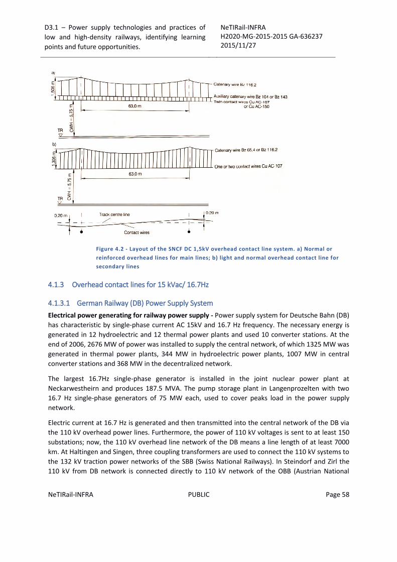
D3.1 – Power supply technologies and practices of
low and high-density railways, identifying learning
points and future opportunities.
NeTIRail-INFRA H2020-MG-2015-2015 GA-636237 2015/11/27
NeTIRail-INFRA PUBLIC Page 58
Figure 4.2 - Layout of the SNCF DC 1,5kV overhead contact line system. a) Normal or
reinforced overhead lines for main lines; b) light and normal overhead contact line for
secondary lines
4.1.3 Overhead contact lines for 15 kVac/ 16.7Hz
4.1.3.1 German Railway (DB) Power Supply System
Electrical power generating for railway power supply - Power supply system for Deutsche Bahn (DB)
has characteristic by single-phase current AC 15kV and 16.7 Hz frequency. The necessary energy is
generated in 12 hydroelectric and 12 thermal power plants and used 10 converter stations. At the
end of 2006, 2676 MW of power was installed to supply the central network, of which 1325 MW was
generated in thermal power plants, 344 MW in hydroelectric power plants, 1007 MW in central
converter stations and 368 MW in the decentralized network.
The largest 16.7Hz single-phase generator is installed in the joint nuclear power plant at
Neckarwestheirn and produces 187.5 MVA. The pump storage plant in Langenprozelten with two
16.7 Hz single-phase generators of 75 MW each, used to cover peaks load in the power supply
network.
Electric current at 16.7 Hz is generated and then transmitted into the central network of the DB via
the 110 kV overhead power lines. Furthermore, the power of 110 kV voltages is sent to at least 150
substations; now, the 110 kV overhead line network of the DB means a line length of at least 7000
km. At Haltingen and Singen, three coupling transformers are used to connect the 110 kV systems to
the 132 kV traction power networks of the SBB (Swiss National Railways). In Steindorf and Zirl the
110 kV from DB network is connected directly to 110 kV network of the OBB (Austrian National

D3.1 – Power supply technologies and practices of
low and high-density railways, identifying learning
points and future opportunities.
NeTIRail-INFRA H2020-MG-2015-2015 GA-636237 2015/11/27
NeTIRail-INFRA PUBLIC Page 59
Railways). Because it is operated as a resonant earthed system, 12 arc suppression coils of 100 A
each, compensate for the line capacitances.
A part of the 110 kV overhead line runs beside the main lines of the DB to supply the individual
substations, which are designed as node-type substations or as simple block-type substations. (6)
4.1.3.2 Standard substations
Function and types of standard substations - As standard definition, substations are electrical
installations with transformers, switchgear, control equipment, metering; also, substations include
protection and signalling facilities with the necessary instrument transformers. With these, it is
possible to switch circuits on and off as required; to switch off faulty equipment and selectively or to
isolate it for maintenance purposes.
With the DB, substations, switching posts and coupling posts for single phase AC 15 kV; 16.7Hz are
designed in accordance with DB directive 995.
DB's standard substations are in operation with no permanent staff and consist of standardized
components with standard interfaces, which can be put together and rated in a modular manner
according to functional requirements.
The standard substation types:
Substations (SS) with equipment for 110 kV and 15 kV. This type of station converts the 110
kV nominal voltage from the transmission line network with frequency 16.7 Hz, to the 15 kV
nominal voltage of the overhead contact lines. They distribute the traction power to the
individual feeding branches.
Switching stations with only equipment for 110 kV. They are used to connect and branch
the 110 kV electrical traction lines.
Switching Posts (SP) with a several 15 kV supply branches. Switching posts connect the
overhead contact lines and feeders of several railway lines and supply overhead contact line
sections supplied from one end with 15 kV power.
Coupling Posts (CP) with one 15 kV circuit breaker only. These railway installations connect
two feeding sections and are used especially in cases of long distances between substations
or long sections fed from one end to guarantee safety and protection in functioning.
The standardized interfaces and components enable using, achievement and development of
functionally equivalent equipment of various manufactures. Old generation substations still contain
pneumatically operated circuit breakers, control, signalling, and protection technology with mostly
mechanical relays.
A substation could have several branches: traction power supply lines, transformer and longitudinal
isolation branches or block branches which are chosen according to the local requirements from
standard branch types. A typical block-type substation plan view is shown in Figure 4.3.

D3.1 – Power supply technologies and practices of
low and high-density railways, identifying learning
points and future opportunities.
NeTIRail-INFRA H2020-MG-2015-2015 GA-636237 2015/11/27
NeTIRail-INFRA PUBLIC Page 60
Standard specifications for the electrical, mechanical and geometrical design are intended to help
achievement and interchange ability of equivalent types of equipment from different manufacturers.
Figure 4.3 – Substation - Plan view
For outdoor installation the 15 MVA single-phase oil transformers is used; the transformers are
insulated against earth and earthed by tank leakage protection transformers.
In DB substations and switching posts the equipment are arranged in two rows of steel racks with a
centre passage, protected by doors from steel and an anti-arcing ceiling. To detect short-circuits the
main frame and the steel rack are insulated from the building and earthed through a rack current
transformer with a transformation ratio of 1.000 to 1. A typical substation and switching post is
shown in Figure 4.3

D3.1 – Power supply technologies and practices of
low and high-density railways, identifying learning
points and future opportunities.
NeTIRail-INFRA H2020-MG-2015-2015 GA-636237 2015/11/27
NeTIRail-INFRA PUBLIC Page 61
Figure 4.4 - Substation and switching posts – Arrangements for medium voltage and
secondary technology
50 VA voltage transformers are used to monitor overhead contact line and bar voltages, in coupling
posts and switching posts. High-voltage fuses are installed upstream of the voltage transformers. To
limit the current during overhead contact line testing, a high-voltage resistor is installed in the test
branch, which is protected by high-voltage fuses started by signals level. (11)
4.1.3.3 Auxiliary supply for substation
Main purpose of the auxiliaries' power supply - Figure 4.5 - for substations and switching posts is to
separates the supplied equipment into two or three groups according to their importance to
maintain the functional capabilities of the equipment and so the electric traction operation. The first
group consists of equipment that can be disposable for brief periods: Panel 1 - Figure 4.5. This group
includes lighting, the power sockets and heating. The second group includes continuously required
equipment such as protection, SCADA and the equipment drives.
Equipment requiring AC 230 V without interruption such as transmission device carrier frequency
modulators PLCT, disconnections devices and electric signals of emergency neutral sections are
supplied with a nominal voltage of 230 V by an additional AC 230 V /50 Hz distribution Panel 3. The
fail-safe voltage for Panel 3 is provided by DC/ AC inverters that are supplied with DC 60 V from the
fail-safe voltage of Panel 2.
A special case is the auxiliaries' supply at coupling posts, where the 15 kV voltage of the overhead
contact line is transformed to the required voltage by auxiliaries' transformer and the battery is
charged by separate rectifiers.
Figure 4.5 – Substation and switching posts – Schematic diagram of the auxiliary’s supply
(continue line – contained in every installation; interrupted line – installed only required)
The isolating transformers are range from 10 kVA to 40 kVA; these are depending by the substation
size and provide supply protection and interference isolation from the local AC 50 Hz network.
Panel 1 can have a connection for an additional stand-by generator unit, which would be provided if
the local network failed for more than five hours.

D3.1 – Power supply technologies and practices of
low and high-density railways, identifying learning
points and future opportunities.
NeTIRail-INFRA H2020-MG-2015-2015 GA-636237 2015/11/27
NeTIRail-INFRA PUBLIC Page 62
Protection Design – Coupling posts benefit from overhead contact line protection. In switching
posts, the general protection is supplemented. Block substations have additional transformer
protection. The switching stations, without transformers, only overhead power line protection is
used. All other substations are equipped with general protection, overhead contact line protection,
transformer and traction power line protection.
4.1.3.4 Supervisory control and data acquisition system
The supervisory control and data acquisition system (SCADA) is a central system for control of
switchgear, automation of switching operations, processing signal and measured values, data
transfer in substations. SCADA was used in the mid-1970s as a recording system and has been
developed becoming a multifunctional substation control system with data display technology.
The SCADA consists of the following functional parts: Local control; Automation components; Signal
and measured value processing; Digital meter monitoring and processing (DMM); Remote control
system; Interlocking.
Local control was used until 1993 in aspects the form of push buttons on the front panel of the
control cubicles. The data are displayed through TFT monitors with full graphics in window
technology.
Numerous additional functions such as securing, locking, storing, acknowledging, adoption of
responsibility, the fault reporting list, the operational reporting journal, general inquires and
parameter adjustment facilities enable dialogue between the operator and the SCADA.
The following are the automatic operation and reduce the work of the operating personnel:
Automatic overhead contact line testing (ACLT);
Automatic overhead contact line reverse polarity testing (ACLRT);
Automatic overhead contact line re-closing (ACLR);
Automating of emergency neutral sections (AENS);
15 kV and 110 kV automatic synchronising device (ASD).
Automatic overhead contact line testing (ACLT) verifies that the overhead contact line branches are
free from short-circuits, before the circuit breaker is switched on and off, this is done after every
activation of an overhead contact line protection unit.
Automatic overhead contact line residual voltage testing (ACLRT) checks the residual voltage of an
overhead contact line branch, when a command is issued to close an earthed disconnector.
Automatic overhead contact line re-closing (ACLR) used in standard substations, without test
branches automatically, re-closes the corresponding circuit breaker after a protection unit has
responded.
Automating of emergency neutral section (AENS) controls the disconnectors and electric signals of
the neutral section located in the network of the DB. They are dependent on the switching state of
the feeding circuit breakers and disconnectors.
D3.1 – Power supply technologies and practices of
low and high-density railways, identifying learning
points and future opportunities.
NeTIRail-INFRA H2020-MG-2015-2015 GA-636237 2015/11/27
NeTIRail-INFRA PUBLIC Page 63
Automatic synchronising device (ASD) verifies the synchronising conditions before enabling the on
command for the circuit breakers. These include the phase synchronization and equal amplitude,
considering permissible voltage differences caused by different line loads.
4.1.3.5 Supporting structures involved
The standardised buildings, used to house the 15kV substation equipment and the secondary
components are constructed of prefabricated parts with integrated thermal insulation, i.e. sandwich
design, on strip foundations and a concrete slab. The reinforcement of all concrete parts including
the prefabricated roof is connected via earthed rods to the foundation earth electrode creating a
Faraday cage. The short circuit current capability of these earth conductors is 40 kA for a duration
time at maximum 1 s.
The foundation earth in switching posts is connected through the main potential compensation bar
and earthed cables. In substations the foundation earth is connected to return conductor cable from
the main tracks.
The individual rooms are separated by fire walls and fire prevention doors. The 15 kV room is
designed for a positive pressure of 0.16 Bar and is equipped with ventilation flaps for air pressure
compensation and temperature. Tubular openings are used for the entry of the cables. A sandwich
floor is used for laying cables within the building. The room for the secondary equipment, known as
the auxiliary room, is equipped with forced ventilation above the battery.
Switching stations for 110 kV do not have a 15 kV section; the minimum permissible room
temperature in unmanned units is 5 °C in the auxiliary power room and -5 °C in the medium-voltage
room.
Related to 110 kV outdoor switching equipment in substations are used galvanised equipment
supports installed in sheaths of standardised round or block foundations made of cast concrete or of
prefabricated parts. The type of foundation also depends on the subsoil conditions. Standard
arrangements for 110 kV branches and required clearances are specified by DIN VDE 0101 and EN
50110. The transformer foundations in the substations, which must bear a mass of over 50 tonnes,
are equipped with an oil drip tray, the level of which is constantly monitored. They are located at a
loading rail or at a substation road suitable for heavy transport.
The earth of all structural steel components and the ball earthed components is carried out by the
mesh electrode connected in substations to the neutral bar cubicle.
4.1.3.6 Development, functions and design for power system control:
The power system control of the DB includes the total of all technical equipment used for the
operation of the traction power and overhead contact line networks, also for equipment used for
operation in substations, converter stations and power plants. Its design and principle functions are
related to traction power feeding via overhead contact lines, the unmanned substations and the
increased requirements for safe and economic operation.
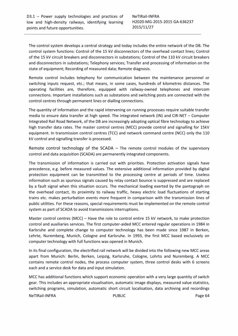
D3.1 – Power supply technologies and practices of
low and high-density railways, identifying learning
points and future opportunities.
NeTIRail-INFRA H2020-MG-2015-2015 GA-636237 2015/11/27
NeTIRail-INFRA PUBLIC Page 64
The control system develops a central strategy and today includes the entire network of the DB. The
control system functions: Control of the 15 kV disconnectors of the overhead contact lines; Control
of the 15 kV circuit breakers and disconnectors in substations; Control of the 110 kV circuit breakers
and disconnectors in substations; Telephony services; Transfer and processing of information on the
state of equipment; Recording of measured data; Remote diagnosis.
Remote control includes telephony for communication between the maintenance personnel or
switching inputs request, etc.; that means, in some cases, hundreds of kilometres distances. The
operating facilities are, therefore, equipped with railway-owned telephones and intercom
connections. Important installations such as substations and switching posts are connected with the
control centres through permanent lines or dialling connections.
The quantity of information and the rapid intervening on running processes require suitable transfer
media to ensure data transfer at high speed. The integrated network (IN) and CIR-NET – Computer
Integrated Rail Road Network, of the DB are increasingly adopting optical fibre technology to achieve
high transfer data rates. The master control centres (MCC) provide control and signalling for 15kV
equipment. In transmission control centres (TCC) and network command centre (NCC) only the 110
kV control and signalling transfer is processed.
Remote control technology of the SCADA – The remote control modules of the supervisory
control and data acquisition (SCADA) are permanently integrated components.
The transmission of information is carried out with priorities. Protection activation signals have
precedence, e.g. before measured values. The extensive additional information provided by digital
protection equipment can be transmitted to the processing centre at periods of time. Useless
information such as spurious signals caused by relay contact bounce is suppressed and are replaced
by a fault signal when this situation occurs. The mechanical loading exerted by the pantograph on
the overhead contact, its proximity to railway traffic, heavy electric load fluctuations of starting
trains etc. makes perturbation events more frequent in comparison with the transmission lines of
public utilities. For these reasons, special requirements must be implemented on the remote control
system as part of SCADA to avoid transmissions interruptions.
Master control centres (MCC) – Have the role to control entire 15 kV network, to make protection
control and auxiliaries services. The first computer-aided MCC entered regular operations in 1984 in
Karlsruhe and complete change to computer technology has been made since 1987 in Berken,
Lehrte, Nuremberg, Munich, Cologne and Karlsruhe. In 1993, the first MCC based exclusively on
computer technology with full functions was opened in Munich.
In its final configuration, the electrified rail network will be divided into the following new MCC areas
apart from Munich: Berlin, Berken, Leipzig, Karlsruhe, Cologne, Lohrto and Nuremberg. A MCC
contains remote control nodes, the process computer system, three control desks with 6 screens
each and a service desk for data and input simulation.
MCC has additional functions which support economic operation with a very large quantity of switch
gear. This includes an appropriate visualisation, automatic image displays, measured value statistics,
switching programs, simulation, automatic short circuit localisation, data archiving and recordings

D3.1 – Power supply technologies and practices of
low and high-density railways, identifying learning
points and future opportunities.
NeTIRail-INFRA H2020-MG-2015-2015 GA-636237 2015/11/27
NeTIRail-INFRA PUBLIC Page 65
for short-circuits, interfering overhead contact line currents and control actions. The MCC also
contains the remote control substation for the exchange of 110 kV related information with the
general control level.
Transmission control and network command centres – For the operation of the network at the
110 kV voltage level, the electrified network of the DB was divided into the four transmission control
centres (TCC): Lehrte, Munich, Cologne and Dresden.
For control optimising, the meter values and circuit breaker position signals of the power plants are
transferred every minute to Frankfurt/M; also, the substations transmit every five minutes.
The network command centre (NCC) at Frankfurt occupies the highest place in the hierarchy of the
power system control of the DB. It controls the use of power from railway owned and external
country producers of 16.7 Hz energy by optimised energy import, the distribution of energy through
substations and the exchange of energy with the interconnected grid partners: Austrian and Swiss
Federal Railway.
4.1.3.7 Overhead contact line model Siemens Sicat S1.0 AC
Figure 4.6 - Layout of Siemens overhead contact line design Sicat S1.0.
In Germany Siemens designed the contact line system Sicat S1.0 AC for speeds up to 230 km/h (see
Figure 4.6). It consists of a catenary wire Bz 50 and a contact wire CuAgAC-100, tensioned with 10 kN
and 12 kN respectively. Stitch wires are used with lengths of 14 m for push-off support and 18 m for
pull off support. The system height at single support is 1.6 m. The lines Stendal-Uelzen, Itzehoe-
Elmshorn and airport link Cologne-Bonn have been equipped with this design. (12)

D3.1 – Power supply technologies and practices of
low and high-density railways, identifying learning
points and future opportunities.
NeTIRail-INFRA H2020-MG-2015-2015 GA-636237 2015/11/27
NeTIRail-INFRA PUBLIC Page 66
4.1.3.8 Overhead contact line model Siemens Sicat H1.0
Figure 4.7 - Layout of Siemens overhead contact line design Sicat H1.0.
The Siemens overhead contact line design Sicat H1.0 developed for running speeds up to 350 km/h
was first employed for the new high-speed line Cologne to Frankfurt (see Figure 4.7). Compared with
the DB AG overhead contact line systems there are some modifications resulting in reduced
investment and operating costs, without impairing the running characteristics. (13) (14)
4.1.3.9 Standard overhead contact line at OBB
When the Austrian Federal Railway (OBB) renewed the Otztal - Haiming section on the Innsbruck -
Bludenz line, a low maintenance design was achieved using rectangular concrete poles and
aluminium cantilevers.
The contact line consists of a 70 mm2 copper catenary wire and a Cu AC-120 contact wire. OBB
implemented the contact line mainly as single-ended tensioning sections with a maximum length of
750 m and equipped with fixed terminations on one end and automatic flexible tensioning devices
on the other. The layout of the standard contact line system is illustrated in Figure 4.8.
The parallel feeder line, consisting of ACSR 260/23, is supported on line post insulators at the pole
top (see Figure 4.9). OBB uses a flexible head-span design for supporting the contact line in stations.
Energised upper cross-span wires and catenary wire supports with droppers are mainly used. The
cross-span wires are attached to the rectangular concrete poles using springs.

D3.1 – Power supply technologies and practices of
low and high-density railways, identifying learning
points and future opportunities.
NeTIRail-INFRA H2020-MG-2015-2015 GA-636237 2015/11/27
NeTIRail-INFRA PUBLIC Page 67
Figure 4.8 - Layout of OBB standard overhead contact line for new lines, Austria.
Figure 4.9 - Pole with OBB cantilevers on the Otzal – Haiming section, Austria
4.1.3.10 Overhead contact line designs S20 and S25 at JBV
Norwegian Jernbaneverket (JBV) operates an 15kVac / 16.7Hz network with overhead contact line
designs S20 for speeds up to 200 km/h and S25 up to 250 km/h. The S25 system was employed for
the high-speed line Oslo-Gardermoen with line speeds up to 250 km/h (see Figure 4.10). This contact
line system is equipped with stitch wires.
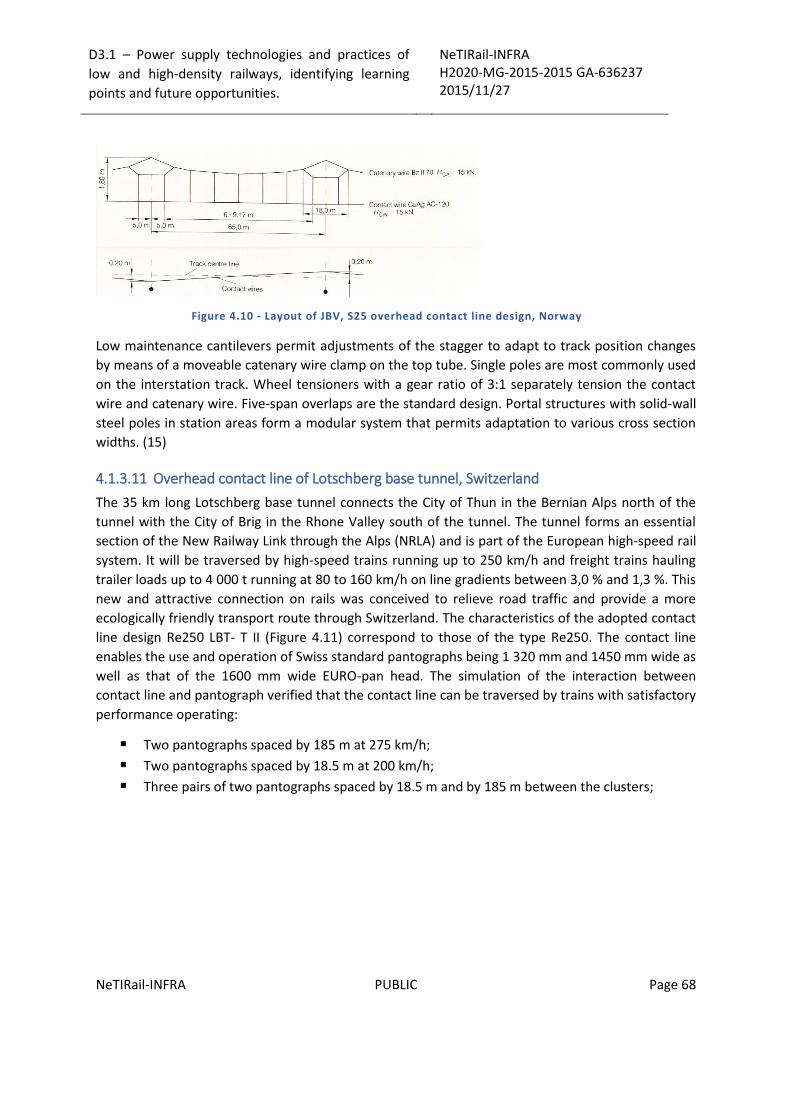
D3.1 – Power supply technologies and practices of
low and high-density railways, identifying learning
points and future opportunities.
NeTIRail-INFRA H2020-MG-2015-2015 GA-636237 2015/11/27
NeTIRail-INFRA PUBLIC Page 68
Figure 4.10 - Layout of JBV, S25 overhead contact line design, Norway
Low maintenance cantilevers permit adjustments of the stagger to adapt to track position changes
by means of a moveable catenary wire clamp on the top tube. Single poles are most commonly used
on the interstation track. Wheel tensioners with a gear ratio of 3:1 separately tension the contact
wire and catenary wire. Five-span overlaps are the standard design. Portal structures with solid-wall
steel poles in station areas form a modular system that permits adaptation to various cross section
widths. (15)
4.1.3.11 Overhead contact line of Lotschberg base tunnel, Switzerland
The 35 km long Lotschberg base tunnel connects the City of Thun in the Bernian Alps north of the
tunnel with the City of Brig in the Rhone Valley south of the tunnel. The tunnel forms an essential
section of the New Railway Link through the Alps (NRLA) and is part of the European high-speed rail
system. It will be traversed by high-speed trains running up to 250 km/h and freight trains hauling
trailer loads up to 4 000 t running at 80 to 160 km/h on line gradients between 3,0 % and 1,3 %. This
new and attractive connection on rails was conceived to relieve road traffic and provide a more
ecologically friendly transport route through Switzerland. The characteristics of the adopted contact
line design Re250 LBT- T II (Figure 4.11) correspond to those of the type Re250. The contact line
enables the use and operation of Swiss standard pantographs being 1 320 mm and 1450 mm wide as
well as that of the 1600 mm wide EURO-pan head. The simulation of the interaction between
contact line and pantograph verified that the contact line can be traversed by trains with satisfactory
performance operating:
Two pantographs spaced by 185 m at 275 km/h;
Two pantographs spaced by 18.5 m at 200 km/h;
Three pairs of two pantographs spaced by 18.5 m and by 185 m between the clusters;

D3.1 – Power supply technologies and practices of
low and high-density railways, identifying learning
points and future opportunities.
NeTIRail-INFRA H2020-MG-2015-2015 GA-636237 2015/11/27
NeTIRail-INFRA PUBLIC Page 69
Figure 4.11 - Overhead contact line Re250 LBL-T II at Lotschberg Base Tunnel
Figure 4.12 - Pole pair in overlaps of Lotschberg-Bahn, Switzerland
The planned traffic, with car and lorry shuttle trains required provisions to adapt the contact wire
height to the enlarged vehicle gauge. After conversion, contact wire height and system height will be
5.75 m and 0.75 m, respectively. The span length will be halved such that the length of the droppers
will not fall below 0.5 m. The arrangements to parallel and tension contact wires and catenary wires
separately are installed 700 m apart and stretch over three spans. The clearance between the
contact lines of insulated overlaps is 0.30 m. The current-carrying capacity of the contact line Re250
LBT-T II is 756A with a new unworn contact wire. The cantilevers, having a single arm design, are
made from corrosion-resistant material and are equipped with water and pollution repellent
composite insulators as security rupture and vandalism (see Figure 4.12). Additional connections
bridge the joints in the cantilevers maintaining the mobility of the cantilever also after short circuits.
(16) (17) (7)
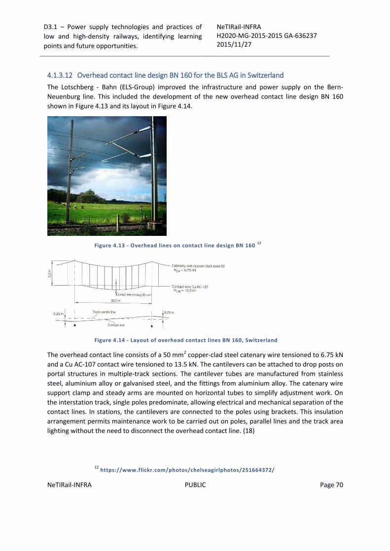
D3.1 – Power supply technologies and practices of
low and high-density railways, identifying learning
points and future opportunities.
NeTIRail-INFRA H2020-MG-2015-2015 GA-636237 2015/11/27
NeTIRail-INFRA PUBLIC Page 70
4.1.3.12 Overhead contact line design BN 160 for the BLS AG in Switzerland
The Lotschberg - Bahn (ELS-Group) improved the infrastructure and power supply on the Bern-
Neuenburg line. This included the development of the new overhead contact line design BN 160
shown in Figure 4.13 and its layout in Figure 4.14.
Figure 4.13 - Overhead lines on contact line design BN 160 12
Figure 4.14 - Layout of overhead contact lines BN 160, Switzerland
The overhead contact line consists of a 50 mm2 copper-clad steel catenary wire tensioned to 6.75 kN
and a Cu AC-107 contact wire tensioned to 13.5 kN. The cantilevers can be attached to drop posts on
portal structures in multiple-track sections. The cantilever tubes are manufactured from stainless
steel, aluminium alloy or galvanised steel, and the fittings from aluminium alloy. The catenary wire
support clamp and steady arms are mounted on horizontal tubes to simplify adjustment work. On
the interstation track, single poles predominate, allowing electrical and mechanical separation of the
contact lines. In stations, the cantilevers are connected to the poles using brackets. This insulation
arrangement permits maintenance work to be carried out on poles, parallel lines and the track area
lighting without the need to disconnect the overhead contact line. (18)
12 https://www.flickr.com/photos/chelseagirlphotos/251664372/

D3.1 – Power supply technologies and practices of
low and high-density railways, identifying learning
points and future opportunities.
NeTIRail-INFRA H2020-MG-2015-2015 GA-636237 2015/11/27
NeTIRail-INFRA PUBLIC Page 71
4.1.4 Overhead contact lines for 25 kVac/ 50Hz
4.1.4.1 High-speed contact line on the Madrid-Seville line
The Madrid-Seville high-speed line of the Spanish State Railway (RENFE) was completed in 1992
between Madrid and Seville.
At the beginning, starting and ending railway stations where Atocha (Madrid) and St. Justa (Seville),
with approximately 470 km long line. Power supply configuration: 8.5 km section, from Atocha,
electrified with 3 kVdc, and 12.5 km section electrified from St. Justa. The remaining 450 km of line
between the two systems separating sections were electrified with single phase 25 kVac/ 50 Hz and
can be travelled at 300 km/h. In 2002, all DC sections were converted to 25 kVac/ 50 Hz power
supply.
Two traction power units of 8.8 MW and substations interval less than 50 km are used. This includes
the power requirement of the auxiliary loads such as railway stations, point heating and technical
buildings of the signal service. The traction power supply of the line is provided by twelve 25 kVac /
50 Hz substations which are powered by 220 kVac and 132 kVac three phase installations from the
Spanish public grid. The primary connection of the 25 kVac/ 50 Hz substations to the three-phase
network was made to take advantage of the highest possible symmetry of the load for AC circuits.
The overhead contact line design with a catenary wire Bz 70 and a contact wire Cu AC-120 is similar
to the DB design Re250. Return current conductors are mounted on the poles to improve the current
return. The turnouts and crossovers are wired with intersecting overhead contact lines. Neutral
sections separate the sections supplied by individual substations in the case of AC 25 kV/ 50 Hz
traction power supplies. Neutral sections were also installed to separate sections supplied by 3 kVdc
and 25kVac/ 50Hz from 1992 to 2002 (Figure 4.15).
Figure 4.15 - Madrid-Seville high-speed line, neutral section between DC and AC power
supply, Spain
Substations of the Madrid-Seville railway have uniform design. Their general circuit design has
similarity with DB's block-type substation.

D3.1 – Power supply technologies and practices of
low and high-density railways, identifying learning
points and future opportunities.
NeTIRail-INFRA H2020-MG-2015-2015 GA-636237 2015/11/27
NeTIRail-INFRA PUBLIC Page 72
Figure 4.16 - Plan view station for Madrid - Seville railway
The main transformers have a nominal power rating of 20 MVA each and are designed for a load of
150 % for 15 minutes and 200 % for 6 minutes needed operations at nominal power. The circuit
breakers are intended for nominal currents of 1600 A and a cut-off capacity of 25 kA. The test
resistor allows test currents of 5 A. The auxiliary transformers have a nominal power rating of 100
kVA and simultaneously supply the neighbouring three-phase switch gear with auxiliary power.
Protection design includes the overhead contact line protection, the transformer and general
protection in the same way as at DB's block-type substations. Because of the single ended powering
it is possible to distribute the power supply with distance protection as part of the overhead contact
line protection. The control design is based on substation control and protection system technology
as DB (Deutsche Bahn) control but without data displays. Automatic overhead contact line testing
and automatic return voltage testing are included as automation components. (19) (3) (4) (7)
4.1.4.2 Overhead contact line on the La Sagra-Toledo branch
The overhead contact line system Sicat H1.0 is used for La Sagra branch of the new Madrid-Toledo
high-speed line. The span length is 65 m. On the new line 5300 mm constant contact wire height and
1600 mm system height were used. The overlapping section for the tensioning of individual sections
extends over three spans.
The insulators within the cantilevers consist of a composite design with glass fibre reinforced cores
and silicone rubber sheds. The fittings of the cantilevers are made of aluminium alloy and connected
by stainless steel bolts (Figure 4.17).
D3.1 – Power supply technologies and practices of
low and high-density railways, identifying learning
points and future opportunities.
NeTIRail-INFRA H2020-MG-2015-2015 GA-636237 2015/11/27
NeTIRail-INFRA PUBLIC Page 73
Figure 4.17 - Cantilever of the La Sagra-Toledo line
The contact lines are installed on welded lattice steel poles. These are mounted on auger-bored
foundations made of reinforced concrete. The connection between the foundations and the poles is
carried out by anchor bolts using threaded reinforcing steel bars. (20)
4.1.4.3 High-speed contact line on TGV lines at SNCF, France
The French State Railway SNCF operates about 1840 km of high-speed lines designed for speeds of
300 km/h and above, which are supplied by 1 or 2 at 25 kVac / 50 Hz traction power; Table 4.1 lists
these lines. The lines are equipped with four major generations of contact line designs with gradual
improvements. The main components like clamps, steady arms, etc. are common to these designs
for maintenance efficiency and stock management.
On the Paris-Lyon line a design with stitch wires has been installed. The tensile force of the copper
Cu AC-120 contact wire is 15 kN. The line was designed for 260 km/h but has been used in 2009
partially at 270 km/h and 300 km/h.
For the Paris-Le Mans/Tours line the design speed was increased to 300 km/h. Therefore, a contact
wire Cu AC-150 with a tensile force of 20 kN was adopted.
Figure 4.19 illustrates a single pole with cantilever and support for the AC 25 kV negative feeder. The
design of the contact wire registration permits a contact wire lift of up to 400 mm. H-beam steel
poles are widely employed in France. The wheel tensioner with a gear ratio 5:1 provides
compensation for the contact wire and catenary wire length variations due to thermal effects and
loadings.
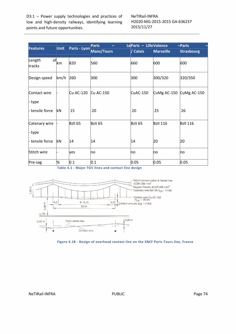
D3.1 – Power supply technologies and practices of
low and high-density railways, identifying learning
points and future opportunities.
NeTIRail-INFRA H2020-MG-2015-2015 GA-636237 2015/11/27
NeTIRail-INFRA PUBLIC Page 74
Features Unit Paris - Lyon Paris – Le
Mans/Tours
Paris – Lille
/ Calais
Valence –
Marseille
Paris –
Strasbourg
Length of
tracks km 820 560 660 600 600
Design speed km/h 260 300 300 300/320 320/350
Contact wire
- type
- tensile force
-
kN
Cu AC-120
15
Cu AC-150
20
CuAC-150
20
CuMg AC-150
25
CuMg AC-150
26
Catenary wire
- type
- tensile force
-
kN
Bzll 65
14
BzII 65
14
BzII 65
14
BzII 116
20
Bzll 116
20
Stitch wire - yes no no no no
Pre-sag % 0.1 0.1 0.05 0.05 0.05 Table 4.1 - Major TGV lines and contact line design
Figure 4.18 - Design of overhead contact line on the SNCF Paris -Tours line, France
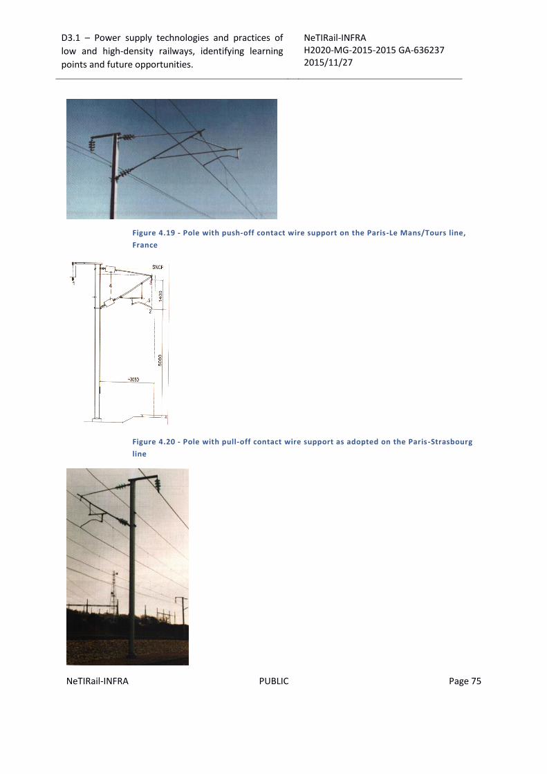
D3.1 – Power supply technologies and practices of
low and high-density railways, identifying learning
points and future opportunities.
NeTIRail-INFRA H2020-MG-2015-2015 GA-636237 2015/11/27
NeTIRail-INFRA PUBLIC Page 75
Figure 4.19 - Pole with push-off contact wire support on the Paris-Le Mans/Tours line,
France
Figure 4.20 - Pole with pull-off contact wire support as adopted on the Paris -Strasbourg
line
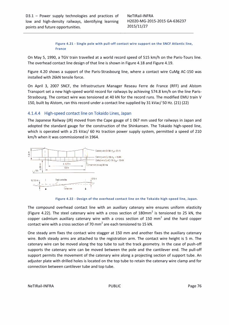
D3.1 – Power supply technologies and practices of
low and high-density railways, identifying learning
points and future opportunities.
NeTIRail-INFRA H2020-MG-2015-2015 GA-636237 2015/11/27
NeTIRail-INFRA PUBLIC Page 76
Figure 4.21 - Single pole with pull-off contact wire support on the SNCF Atlantic line,
France
On May 5, 1990, a TGV train travelled at a world record speed of 515 km/h on the Paris-Tours line.
The overhead contact line design of that line is shown in Figure 4.18 and Figure 4.19.
Figure 4.20 shows a support of the Paris-Strasbourg line, where a contact wire CuMg AC-150 was
installed with 26kN tensile force.
On April 3, 2007 SNCF, the Infrastructure Manager Reseau Ferre de France (RFF) and Alstom
Transport set a new high-speed world record for railways by achieving 574.8 km/h on the line Paris-
Strasbourg. The contact wire was tensioned at 40 kN for the record runs. The modified EMU train V
150, built by Alstom, ran this record under a contact line supplied by 31 kVac/ 50 Hz. (21) (22)
4.1.4.4 High-speed contact line on Tokaido Lines, Japan
The Japanese Railway (JR) moved from the Cape gauge of 1 067 mm used for railways in Japan and
adopted the standard gauge for the construction of the Shinkansen. The Tokaido high-speed line,
which is operated with a 25 kVac/ 60 Hz traction power supply system, permitted a speed of 210
km/h when it was commissioned in 1964.
Figure 4.22 - Design of the overhead contact line on the Tokaido high-speed line, Japan.
The compound overhead contact line with an auxiliary catenary wire ensures uniform elasticity
(Figure 4.22). The steel catenary wire with a cross section of 180mm2 is tensioned to 25 kN, the
copper cadmium auxiliary catenary wire with a cross section of 150 mm2 and the hard copper
contact wire with a cross section of 70 mm2 are each tensioned to 15 kN.
One steady arm fixes the contact wire stagger at 150 mm and another fixes the auxiliary catenary
wire. Both steady arms are attached to the registration arm. The contact wire height is 5 m. The
catenary wire can be moved along the top tube to suit the track geometry. In the case of push-off
supports the catenary wire can be moved between the pole and the cantilever end. The pull-off
support permits the movement of the catenary wire along a projecting section of support tube. An
adjuster plate with drilled holes is located on the top tube to retain the catenary wire clamp and for
connection between cantilever tube and top tube.

D3.1 – Power supply technologies and practices of
low and high-density railways, identifying learning
points and future opportunities.
NeTIRail-INFRA H2020-MG-2015-2015 GA-636237 2015/11/27
NeTIRail-INFRA PUBLIC Page 77
Damping elements inserted between the contact wire and the auxiliary catenary wire are designed
to limit vibrations in the contact line system. The contact wire is attached to the auxiliary catenary
wire through the rigid droppers.
While single poles are predominant on the interstation tracks, portals support the con-tact lines in
stations. The tensioning section lengths are 1 500 m. Five span overlaps provide transitions between
the individual tension lengths. (23) (24)
4.1.4.5 High-speed contact line Sicat HA C on the Beijing-Tianjin line, China
The Beijing-Tianjin high-speed line of the Chinese Ministry of Railways (MOR) with an operational
speed of 350 km/h was completed in July 2008. The catenary system in use is Sicat HA C with
aluminium cantilever; it is powered by two sub-stations at 25kVac/ 50 Hz; the overhead contact line
is equipped with a catenary wire Bz 120. The maximum span length is only 50 m.
Figure 4.23 - Overhead contact line Sicat HA C for the Beijing-Tianjin line, China.
There are no Y-stitch wires at the supports. The contact wire height is 5300 mm and the contact wire
pre-sag is 0.05 % of span length or 30mm (Figure 4.23). The design without stitch wires but with a
pre-sag does not provide optimum conditions for high-speed operation. The system height is 1600
mm.
The insulators within the cantilevers consist of ceramic material. The fittings for the cantilevers are
made of aluminium alloy and connected by stainless steel bolts. The overlapping section at the ends
of individual sections extends over five spans. Wheel tensioning devices with a gear ratio of 3:1
compensates for the contact wire and catenary wire length variations due to thermal effects and
loading. The overhead contact line on crossovers uses crossings between traversed contact wires.
Portals carry the contact line supports in this case. The cantilevers are installed on H-beam steel
poles which are mounted with anchor bolts cast in the reinforced concrete of the 115 km long
railway viaduct. The turnouts and crossovers are wired with intersecting overhead contact lines.
Neutral sections separate the sections supplied by two individual substations used for traction
power supply.
4.1.4.6 Contact line type Re 200C for the Harbin-Dalian line, China (24)
This important railway line connects the cities of Harbin, Changchung, Shengyang and Dalian all
having more than one million inhabitants. The line is especially suited for electric operation due to
transport of seven million tons of freight and 25 trains per day and direction having headways of 8 to

D3.1 – Power supply technologies and practices of
low and high-density railways, identifying learning
points and future opportunities.
NeTIRail-INFRA H2020-MG-2015-2015 GA-636237 2015/11/27
NeTIRail-INFRA PUBLIC Page 78
10 minutes. The design of the adopted overhead contact line type Re 200 C is based on DB's
overhead contact line Re200 and is suitable for the local climatic conditions. This is especially true of
the temperature range between -40°C and +80°C being more than that of DB's Re200. The main
tracks are equipped with a contact wire CuAg AC-100, the secondary tracks with contact wire Cu AC-
100 both combined with a catenary wire Bz II50, the tensile force being 10 kN in both cases. The
14m long stitch wire is tensioned to 2.3 kN. Cantilevers and fittings made of aluminium alloy
guarantee a long service life. On interstation lines directly embedded steel-reinforced concrete poles
are used and in stations steel poles or concrete poles set on concrete foundations, cast in-situ.
Reinforcing feeder 243-AL1 and a return conductor 243-AL1 are strung in parallel to the overhead
contact line. The return conductor is arranged close to the reinforcing feeder to achieve a close
inductive coupling such that a high portion of the return current flows through the return conductor.
This reduces the reactance considerably. The magnetic field strength within the contact line area is
low due to the return conductor. This reduces the magnetic field strength in the range of
neighbouring cable installations and, therefore, the interference. (24)
The permissible current carrying capacity of 1270 A for this type of contact line secures a high power
transmission for the transportation of a high number of trains and high loads in the future as well.
4.1.4.7 High-speed contact line type Sicat H1.0 for the HSL Zuid line
The Dutch high-speed line HSL Zuid connects Amsterdam to the high-speed rail system in Belgium.
The line has been supplied with 25 kVac/ 50 Hz and will be used at 300 km/h. The line has been
equipped with the contact line Sicat H1.0 together with negative feeders and return conductors. The
design of the poles had to be adjusted to the design of other structural components - Figure 4.24.
(25)
Figure 4.24 - Contact Line arrangement on an interstation section of the HSL Zuid line; 1 -
negative feeder; 2 – return conductor; 3 – catenary wire; 4 – contact wire.

D3.1 – Power supply technologies and practices of
low and high-density railways, identifying learning
points and future opportunities.
NeTIRail-INFRA H2020-MG-2015-2015 GA-636237 2015/11/27
NeTIRail-INFRA PUBLIC Page 79
4.2 Designing new railway power supply systems – Recommended technical requirements and specifications.
4.2.1 General requirements
The reliability of electric railway operation depends heavily on the availability and reliability of the
traction power supply installation. The requirements of the contact line whether an overhead line
system or a third rail system need to consider that the contact line is the only component in the
traction power supply installation which cannot be installed redundantly for economic and technical
reasons.
The required high availability of the contact line system, therefore, necessitates thorough planning
as early as practicable in the planning cycle for electrification. It should make use of proven, carefully
tested equipment with long service life, correct installation and effective maintenance during
operation. The following basic demands must be made on the design of a contact line installation:
All components of the system should have a long service life. The following specific
requirements are therefore important:
o Adequate mechanical and electrical strength.
o Resistance to loads imposed by wind and ice and aggressive substances in the air.
o Corrosion resistance of all components.
o Uniform, low wear of the contact wire.
Distribution lines for electric power over a particular distance;
Provision of a sliding contact for the current collector under all conditions.
Persons and equipment must not be placed in any danger from the operation of contact
lines.
At all speeds, up to the permissible maximum speed of the contact line type under
consideration, the dynamic interaction of the current collector and the contact line or third
rail has to ensure that interruptions to power transmission do not occur under normal
conditions.
During the design of overhead contact line installations in built-up areas; aesthetic and city-
planning aspects have to be monitored.
Nature and environmental protection have to be taken into account.
The investments for the installation and the costs for operation and maintenance should be
as low as possible during the life cycle of the equipment.
The individual characteristics derived from these basic requirements of a contact line system, can be
classified into mechanical, electrical, environmental, operational and maintenance related aspects,
but a strict distinction between the individual requirements is not always possible.
The overhead contact line has to comply with sophisticated quality criteria for successful power
transmission. There are static quality criteria such as elasticity and its uniformity along the span and
contact wire uplift. The dynamic quality criteria include the wave propagation velocity, the Doppler
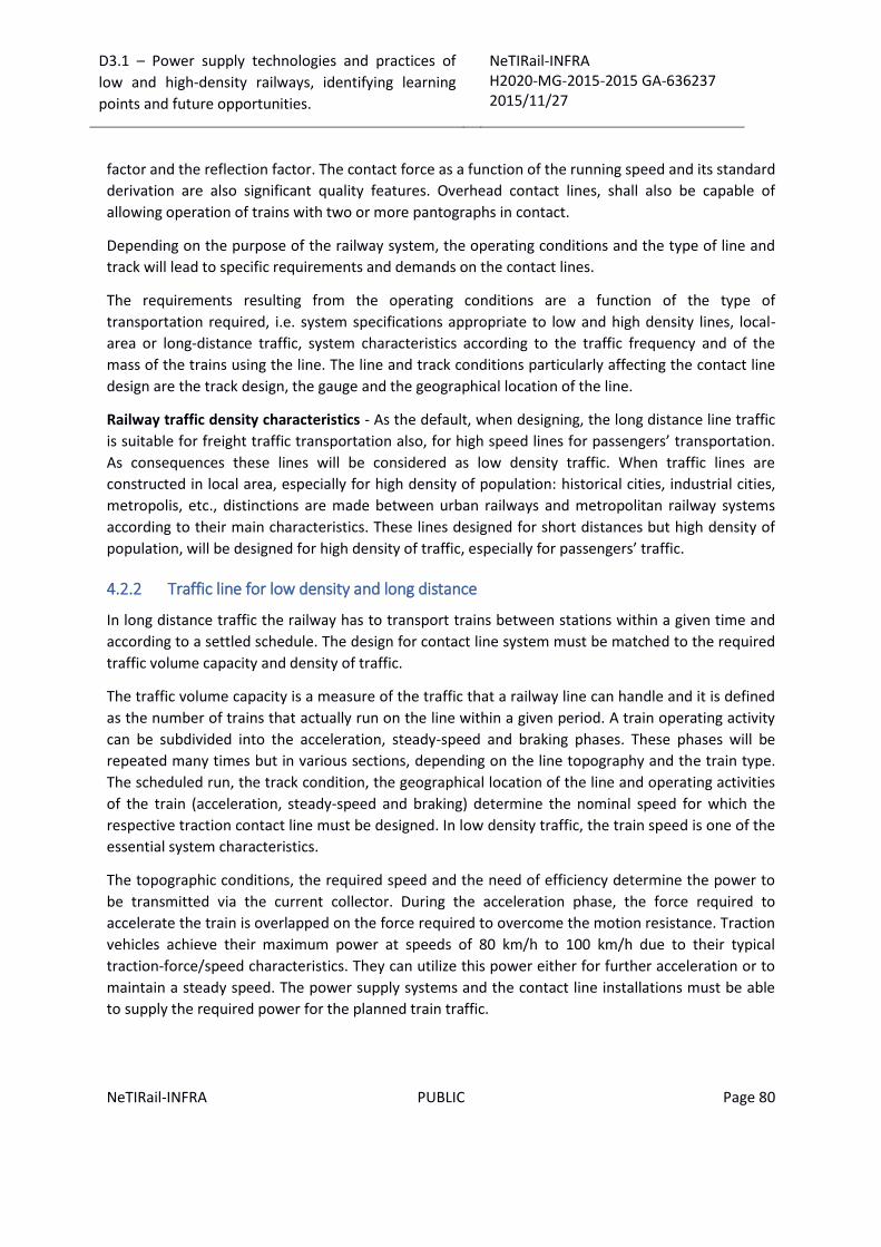
D3.1 – Power supply technologies and practices of
low and high-density railways, identifying learning
points and future opportunities.
NeTIRail-INFRA H2020-MG-2015-2015 GA-636237 2015/11/27
NeTIRail-INFRA PUBLIC Page 80
factor and the reflection factor. The contact force as a function of the running speed and its standard
derivation are also significant quality features. Overhead contact lines, shall also be capable of
allowing operation of trains with two or more pantographs in contact.
Depending on the purpose of the railway system, the operating conditions and the type of line and
track will lead to specific requirements and demands on the contact lines.
The requirements resulting from the operating conditions are a function of the type of
transportation required, i.e. system specifications appropriate to low and high density lines, local-
area or long-distance traffic, system characteristics according to the traffic frequency and of the
mass of the trains using the line. The line and track conditions particularly affecting the contact line
design are the track design, the gauge and the geographical location of the line.
Railway traffic density characteristics - As the default, when designing, the long distance line traffic
is suitable for freight traffic transportation also, for high speed lines for passengers’ transportation.
As consequences these lines will be considered as low density traffic. When traffic lines are
constructed in local area, especially for high density of population: historical cities, industrial cities,
metropolis, etc., distinctions are made between urban railways and metropolitan railway systems
according to their main characteristics. These lines designed for short distances but high density of
population, will be designed for high density of traffic, especially for passengers’ traffic.
4.2.2 Traffic line for low density and long distance
In long distance traffic the railway has to transport trains between stations within a given time and
according to a settled schedule. The design for contact line system must be matched to the required
traffic volume capacity and density of traffic.
The traffic volume capacity is a measure of the traffic that a railway line can handle and it is defined
as the number of trains that actually run on the line within a given period. A train operating activity
can be subdivided into the acceleration, steady-speed and braking phases. These phases will be
repeated many times but in various sections, depending on the line topography and the train type.
The scheduled run, the track condition, the geographical location of the line and operating activities
of the train (acceleration, steady-speed and braking) determine the nominal speed for which the
respective traction contact line must be designed. In low density traffic, the train speed is one of the
essential system characteristics.
The topographic conditions, the required speed and the need of efficiency determine the power to
be transmitted via the current collector. During the acceleration phase, the force required to
accelerate the train is overlapped on the force required to overcome the motion resistance. Traction
vehicles achieve their maximum power at speeds of 80 km/h to 100 km/h due to their typical
traction-force/speed characteristics. They can utilize this power either for further acceleration or to
maintain a steady speed. The power supply systems and the contact line installations must be able
to supply the required power for the planned train traffic.

D3.1 – Power supply technologies and practices of
low and high-density railways, identifying learning
points and future opportunities.
NeTIRail-INFRA H2020-MG-2015-2015 GA-636237 2015/11/27
NeTIRail-INFRA PUBLIC Page 81
The maximum train length will affect the length of platforms; will affect also secondary and main
lines in stations, the passing tracks as well as protective sections, neutral sections and location of
signals. The design of the contact line installation also depends on these factors.
The operating requirements and the power supply systems for long-distance main line traffic are the
factors leading to the use of overhead contact lines as traction energy supply installations for
railways with low traffic density, capable to provide high energy with high voltage to low density of
traction vehicles, in a feeding section. Lines with low density traffic give opportunity to improve the
infrastructure for becoming high speed lines.
Electric railway networks have their own track reserves allowing free choice of pole location. To
achieve mechanical separation of the overhead contact lines of double-track lines, the poles are
placed on the outside edges of the track. In tunnels, the overhead contact line supports can be
located above and between the tracks. The track spacing in tunnels affects overhead line design
solutions.
As example, the German railway company DB (Deutsche Bahn) use a track spacing of 4.5 m for high
speed lines in open air and track spacing in tunnels as different by speed category: 4 m for train
speeds up to 200 km/h; 4.5 m for speeds up to 350 km/h. The SNCF uses a track spacing of 4.20 m
for high-speed lines.
The super-elevation, which may be as high as 180 mm, the track geometry and the location of
switch-points or turnouts are other important factors in the structural design of overhead contact
line installations.
The demands on and design of contact line installations of main lines for long-distance traffic and
low density traffic is strongly influenced by the desired running speeds. The running speeds, in turn,
determine the geometry and topographical location of the railway lines, especially the curve radii
and the associated super-elevation.
Trains with tilting bodies permit a further increase of the running speed by 14 % if passive tilting
mechanisms are used or by as much as 30 % in the case of active tilting mechanism. If the train
speeds in curves are increased, this will have a direct effect on the design of contact line lateral
acceptance forces. Traction vehicles with tilting bodies will sense major lateral displacements of the
pantographs due to the increased centrifugal forces at higher speeds. This means that the
registration of the contact line must be checked and that the lateral contact wire position may need
recalibrating; these will influence also steady arms and/ or cantilevers. Alterations to the overhead
contact line supporting structures are not needed normally if traction vehicles with tilting bodies and
active pantograph controls are used. The maximum gradient is generally limited to maximum 4 %
and on future high-speed lines this value will be limited to 3.5 %.
The clearance gauge is of great importance in contact line design since no components of any kind
are allowed to exceed clearance into this area.
The independent development of railways in various regions in the past has led to different
clearance gauges coded: GA, GB and GC. They have been harmonized by the TSI for Infrastructure
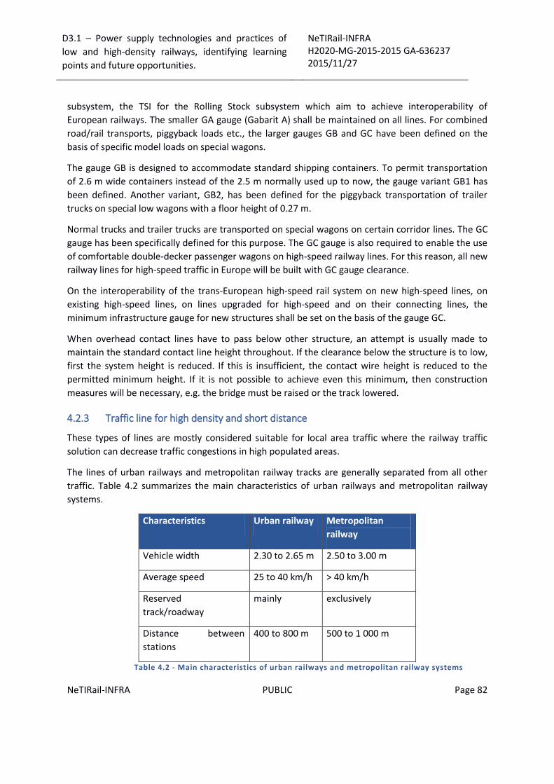
D3.1 – Power supply technologies and practices of
low and high-density railways, identifying learning
points and future opportunities.
NeTIRail-INFRA H2020-MG-2015-2015 GA-636237 2015/11/27
NeTIRail-INFRA PUBLIC Page 82
subsystem, the TSI for the Rolling Stock subsystem which aim to achieve interoperability of
European railways. The smaller GA gauge (Gabarit A) shall be maintained on all lines. For combined
road/rail transports, piggyback loads etc., the larger gauges GB and GC have been defined on the
basis of specific model loads on special wagons.
The gauge GB is designed to accommodate standard shipping containers. To permit transportation
of 2.6 m wide containers instead of the 2.5 m normally used up to now, the gauge variant GB1 has
been defined. Another variant, GB2, has been defined for the piggyback transportation of trailer
trucks on special low wagons with a floor height of 0.27 m.
Normal trucks and trailer trucks are transported on special wagons on certain corridor lines. The GC
gauge has been specifically defined for this purpose. The GC gauge is also required to enable the use
of comfortable double-decker passenger wagons on high-speed railway lines. For this reason, all new
railway lines for high-speed traffic in Europe will be built with GC gauge clearance.
On the interoperability of the trans-European high-speed rail system on new high-speed lines, on
existing high-speed lines, on lines upgraded for high-speed and on their connecting lines, the
minimum infrastructure gauge for new structures shall be set on the basis of the gauge GC.
When overhead contact lines have to pass below other structure, an attempt is usually made to
maintain the standard contact line height throughout. If the clearance below the structure is to low,
first the system height is reduced. If this is insufficient, the contact wire height is reduced to the
permitted minimum height. If it is not possible to achieve even this minimum, then construction
measures will be necessary, e.g. the bridge must be raised or the track lowered.
4.2.3 Traffic line for high density and short distance
These types of lines are mostly considered suitable for local area traffic where the railway traffic
solution can decrease traffic congestions in high populated areas.
The lines of urban railways and metropolitan railway tracks are generally separated from all other
traffic. Table 4.2 summarizes the main characteristics of urban railways and metropolitan railway
systems.
Characteristics Urban railway Metropolitan
railway
Vehicle width 2.30 to 2.65 m 2.50 to 3.00 m
Average speed 25 to 40 km/h > 40 km/h
Reserved
track/roadway
mainly exclusively
Distance between
stations
400 to 800 m 500 to 1 000 m
Table 4.2 - Main characteristics of urban railways and metropolitan railway systems
D3.1 – Power supply technologies and practices of
low and high-density railways, identifying learning
points and future opportunities.
NeTIRail-INFRA H2020-MG-2015-2015 GA-636237 2015/11/27
NeTIRail-INFRA PUBLIC Page 83
For this reason, urban railways should use overhead contact lines, whereas metros may use
conductor rails or overhead contact lines.
The tight, close schedules of traffic, particularly at peak hours, and the low voltage mean that the
contact lines must be able to conduct large currents. This is a characteristic of conductor rails.
Overhead contact lines, often installed as simple trolley-type contact wire without a catenary wire,
should be designed for new lines as catenary solution, providing the advantages of higher speeds;
higher current carrying capacity; better collector running characteristics; less collector strip wear;
less dangerous behaviour in the event of contact wire breakage; longer spans.
The use of vertical catenary suspensions is only avoided in areas where aesthetic urban planning and
architectural aspects do not permit such systems. Then simple trolley-type contact lines with parallel
feeder wires or double contact wires are used instead.
To minimise voltage drops and the associated power loss, the overhead contact lines of both tracks
of double-track lines can be electrically interconnected at regular intervals. Remote-controlled
coupling disconnectors are installed between the tracks on lines where a single-track, two-way
emergency operation is possible if a contact line fault occurs.
On the basis of experience gained with modern over-sized road transports, most urban communities
now install overhead contact wires at heights of 5 m to 5.5 m in the open, and approximately 4 m in
tunnels due to the restricted space available.
The stagger of the contact wire at the supports is usually ± 0.40 m. To prevent grooves from being
formed in the collector strips from localised wear, the stagger variation of the contact wire should be
more than 10 mm/m as the collector strip moves along it.
Recommended gradient of the contact wire: should not exceed 5 mm/m, where the track gradient
changes from level to an uphill or downhill grade; should not exceed 10 mm/m on uphill or downhill
grades;
In an attempt to minimise the overall line width, a central support structure is used wherever
possible, for example, the poles are located between the tracks.
In local area lines, the contact lines are mainly fed at both ends via rectifier substations, ensuring
adequate distribution of the peak currents when trains are accelerating and braking. The contact line
disconnectors and section insulators should be located in the immediate vicinity of the substation to
keep the feed cables to the contact line sections as short as possible.
Section isolation installations should be equipped with remote-controlled contact line disconnectors
for faster response in the event of a fault.
Occasional overcurrent relay tripping cannot be avoided when trains are run at sight. For this reason,
all contact line circuit breakers should be equipped with devices capable of distinguishing between
operating overcurrent and short-circuit currents.

D3.1 – Power supply technologies and practices of
low and high-density railways, identifying learning
points and future opportunities.
NeTIRail-INFRA H2020-MG-2015-2015 GA-636237 2015/11/27
NeTIRail-INFRA PUBLIC Page 84
With the ever-increasing deployment of traction vehicles able to feed braking energy back into the
network, voltages exceeding the nominal traction voltage will occur frequently, meaning that the
insulation of the contact line installations must be designed to resist with these increased voltages.
To reduce energy losses and thus to lower operating costs, an increase of the overhead contact line
voltage to 750 Vdc is recommended. Transmission losses can be reduced by 5% if the voltage is
increased from 600 Vdc to 750 Vdc.
Poles between the tracks are frequently used on lines running on their own reserved right-of-way.
Transport systems that use contact rails should always have their own right-of-way.
In high density traffic from agglomerated area, the operating speeds range is from 80 to 100 km/h.
The design of the contact line installations will not be determined so much by the train speeds as by
the larger currents needed due to the lower traction voltage. Curve radii are also smaller than on
long range and high speed lines. Line gradients up to 11 % may also occur for existing lines but on
newly-planned lines, try it through requirements to limit gradients to maximum 5 %.
In local-area transportation, systems, a much larger variety of clearance gauges is found than in high
speed long range railways. This is a result of the separate development of individual local-area
transport companies and the lack of interoperability requirements.
The increasing importance of combined operations, means the use of the same track by long-
distance and low density trains, local-area trains and trams, as in the case in Karlsruhe, Germany, for
instance, in which illustrates the need to get uniformity gauges.
4.2.4 Climatic requirements for designing new lines
In the design of contact line systems, the climatic conditions applicable for the respective territory
have to be observed. The standard EN 50 125-2 gives guidelines for limits to be considered.
Outdoor temperatures above 350C occur rarely in Central Europe, the annual averages lie between
80C and 100C.
The valid temperature limits in Central Europe are:
Highest temperature of the ambient air +400C;
Lowest ambient temperature -300C;
In France, the average values are approximately 150C. In Russia, the lowest regional outdoor
temperature is to be around -600C.
Equipment of outdoor systems in the housings (e.g. local control facilities) should not suffer
irreversible functional damage between -350C and +700C according to EN 60 529. These statements
apply to altitudes up to 1200 m above sea level.

D3.1 – Power supply technologies and practices of
low and high-density railways, identifying learning
points and future opportunities.
NeTIRail-INFRA H2020-MG-2015-2015 GA-636237 2015/11/27
NeTIRail-INFRA PUBLIC Page 85
4.2.5 Wind velocities and wind loads
The design of contact lines with respect to wind loads involves to two main aspects: Verification of
serviceability, avoidance of pantograph de-wiring caused by wind deflected contact wire; Reliable
design of structural elements to withstand the wind loads which probably will occur during the life
time of the installation.
According to EN 50 119 the verification of serviceability may be carried out based on a wind velocity
having a return period of three years whilst for the structural design of the supports the wind
velocity will have a return period of 50 years for using. Basic information on wind velocities or wind
loads is provided in EN 1991-1-4 or national standards. Information on wind velocities to be used for
railway applications is given in EN 50125-2:2002. Four wind classes are defined, with wind velocities
of 24 m/s; 27.5m/s; 32 m/s and 36 m/s. The values represent 10 min average period, applied to
open flat terrain with low obstacles and at 10 m height above ground. Since the data given in EN 50
125-2:2002 does not refer to a certain location and, therefore, cannot be used directly, national
specifications are applied in most cases. The corresponding data comply with the statistical
characteristics.
Germany, according to DIN 1055 - 4:2005, contains wind zones: W1 (22.5 m/s); W2 (25 m/s); W3
(27.5 m/s); W4 (30 m/s).
France, according to NF EN 1991-1-4:2005, contains wind zones: W1 (22 m/s); W2 (24 m/s); W3 (26
m/s); W4 (27.5 m/s).
Spain contains wind zones: W1 (24 m/s); W2 (28 m/s).
In many cases, railway entities specify design data for wind velocities based on their experience but
differing from current standards.
In France, three wind regions exist where the wind pressure considered in the design, results from
wind velocities of 28.6 m/s, 33.8 m/s and 38.3 m/s. Beyond this, maximum wind velocities are
specified by the SNCF that are greater than the normal wind velocities by a factor. A further
classification is made according to the terrain formation. Protected land, e.g. basins with
surrounding hills, is assessed with a factor of 0.8; normal terrain has a factor of 1.0; exposed terrain
includes seashores, cliffs and narrow valleys; exposed terrain has factors between 1.25 and 1.35
depending on the wind region.
The design of DB's overhead contact lines for conventional lines up to running speeds of 200 km/h
was based on 26 m/s wind speed, which corresponds approximately to the wind velocity in wind
zone 1 – W1 with a return period of three years. For contact lines for high speeds a wind velocity of
33 m/s was applied at heights up 100 m above ground and 37 m/s at heights of more than 100 m.
These specifications were used for bridges and viaducts which were considerably higher than their
surroundings.

D3.1 – Power supply technologies and practices of
low and high-density railways, identifying learning
points and future opportunities.
NeTIRail-INFRA H2020-MG-2015-2015 GA-636237 2015/11/27
NeTIRail-INFRA PUBLIC Page 86
4.2.6 Corrosive substances
Aggressive dust, vapours, gases and extreme levels of humidity can cause rapid contamination of
insulators and increased wear of components in contact line installations, particularly when several
substances are combined. These active airborne substances may occur in the vicinity of production
facilities which emit such substances and near the sea. These factors must be accommodated in the
design of contact line systems.
4.2.7 Lightning voltage surges
Lightning striking the contact line and the overhead line installations can cause flashovers at the
insulation leading to damage. From measurements, it is approximately that one lightning stroke per
100 km of contact line in a year can be assumed in Central Europe. The probability of lightning is
highly variable and also differs according to location.
A direct lightning stroke on an overhead contact line will cause lighting voltage surges.
Indirect lightning voltage surges occur as lightning discharges when an overhead contact line lies in
the electric field between a cloud and the earth. When a thunderstorm approaches, charges are
induced in the overhead contact line, by an electromagnetic field. The negative charges are drained
to earth through the discharge resistance of the numerous parallel contact line insulators and the
positive charges are kept by the field emitted by the cloud. If a cloud then discharges in the vicinity
of an overhead contact line, the charges are released in this line and are propagated as a travelling
wave along the overhead contact line. The indirect lighting overvoltage impulse is lower in
magnitude and rise more slowly than a direct lightning stroke.
In overhead contact line installations, impulse voltage limiting can be achieved by over-voltage
protection devices. The most important over voltage protection device is the valve-type arrestor.
Since only limited protection is possible with over voltage protection devices, they are not used for
economic reasons unless an extreme frequency of lightning exists.
4.2.8 Icing, anti-icing and de-icing of railway contact wires
General considerations - As the principal mode of manifestation, the accumulation of ice on the
conductors of overhead contact lines will cause an additional weighing load on these systems. The
icing of overhead lines from any railway power supply system represents a serious problem for any
network infrastructure. The icing causes a series of technical problems for overhead power supply:
overloading, non-uniform icing, and wire galloping. In countries with cold climates: Northern Europe
countries, U.S.A., Canada, China, etc., glaze and rime deposits on power contact lines and messenger
wires create problems for maintenance activities and people working in these areas.
Due to the added burden of ice or reducing contact between the pantograph and contact line
because the intermediate layer of ice, power cables were damaged or destroyed in numerous
occasions.
D3.1 – Power supply technologies and practices of
low and high-density railways, identifying learning
points and future opportunities.
NeTIRail-INFRA H2020-MG-2015-2015 GA-636237 2015/11/27
NeTIRail-INFRA PUBLIC Page 87
In Russia, in regions with extreme ice loads significantly increased sag has occurred on automatically
tensioned overhead contact lines, that railway operations have been temporarily impeded. Also,
whereas in Germany ice loads must be taken into account, this is unnecessary for SNCF.
Studies of thermo-physics of the environment give a great importance to researching of the
mechanisms of icing and anti-icing. These researches are basics for design of the transmission line
for power supply systems.
Icing from extreme weather may have a negative influence on the infrastructure railway design but
especially for power transmission lines or power railway contact wires. As prior information, there is
no ice types and accumulation database that can be used as statistical information.
The icing process of railway contact wires and corresponding anti-icing technologies are described
here. Four aspects should be considered: the hazards of the icing of railway contact wires; the
characteristics of the icing of railway contact wires and affecting factors, experimental research into
the icing and anti-icing of railway contact wires, creating expert system of the icing and ice melting
of railway contact wires. Large, heavy ice accretions may form on objects exposed to freezing rain.
These can damage or destroy structures and cause great economic and social hardship.
In the United States, Canada, France, Russia, Japan, Korea, etc. are frequently affected by icing on
the power supply transmission lines (public or private) and also for overhead railway power supply
systems. Large areas of south-eastern United States had affected by heavy ice accretion in February
1994; were result economic losses of 30 billion. Again, in 1998 and 2003, the USA and Canada had a
period with major area of wires icing that cause economic losses.
The research of contact wire icing has not developed enough, for the following reasons:
Railways electrification development is relatively late and networks are not on a large area.
The contact wire has not been extended to the areas where ice accretion is frequent;
Icing events at dangerous and destructing levels for railway infrastructure has not happened
in the freezing rain areas for the last tens of years also because of global warming. This
situation put the problem of the contact wire icing low in priority.
Generally, modern electrified railways are designed for busy lines with high traffic:
passengers and cargoes. The time between trains is short and in the limited period, icing is
difficult to grow the thickness which can affect the operation.
It is anticipated that the icing problems for railways network will be highlighted in the future. Some
causes for this tendency are: the continuous extension of the electrification railways, railways
network will pass through topographical regions where conditions have difficult features. In
addition, the downtime of railways will be extended, so the icing problem will be highlighted.
Methods used for de-icing and/or anti-icing are: manual ice removal, thermal de-icing of contact
line, chemical anti-icing, resistive wire de-icing technology.
Manual de-icing - The environmental conditions are difficulty during the period of icing, which
brings difficulty for manual de-icing. Removing snow and ice using human force or machines as help

D3.1 – Power supply technologies and practices of
low and high-density railways, identifying learning
points and future opportunities.
NeTIRail-INFRA H2020-MG-2015-2015 GA-636237 2015/11/27
NeTIRail-INFRA PUBLIC Page 88
is still the simplest but primitive method because it is a time-consuming, inefficient and unsafe
operation (see Figure 4.25 and Figure 4.26).
Figure 4.25 – Manual de-icing from a mobile platform (26)
Figure 4.26 – Manual de-icing from ground (26)

D3.1 – Power supply technologies and practices of
low and high-density railways, identifying learning
points and future opportunities.
NeTIRail-INFRA H2020-MG-2015-2015 GA-636237 2015/11/27
NeTIRail-INFRA PUBLIC Page 89
Contact wire thermal running – This procedure is the simplest and most used. The icing is observed
by staff of the railway, before the operation of overhead contact wire. The staff determine the level
grade of icing. If the ice thickness reaches the warning level, operations for de-icing will be started,
letting the electric current flow through the overhead contact wire. The electric vehicles get power
from the collect strip, letting the collect pantograph strip to keep touching the contact wires in idle
mode, and ice is melted until falls.
Chemical anti-icing - uses chemical substances to decrease the freezing point of water in order to
prevent icing. The most common and most effective is CaCl. The Railroad Car Company in Bremen,
Germany uses the de-icing coating produced by the Stemmann Technik Company to apply to the
contact wires. Also other applications and services can be affected by icing: airports, highways, etc.
Chemical solution means applying the de-icing agents to contact wires and creates some
environmental pollution with chemicals and should be taken in consideration.
Resistive wire heating de-icing – There are specialized some companies: Alston from France and
Hitachi from Japan, developed a de-icing system for overhead contact wire using built-in wire with
insulation resistance characteristics, and applied it to railway and tram systems, for example in
Japan, France, South Korea and the UK. The system for remove icing is similar to process with
composite conductors used in de-icing of high-voltage transmission lines.
This is a good example of taking a technology from a different domain and adapting to the railway
applications.
Negative effects of contact lines when icing:
Quality and performance of the contact wire are decreased - The ice weight added to
the contact will increase the tension of the wires; this would cause the clamp dropper for
messenger wire to break, the mid-anchor clamps are deformed. In glaze ice conditions, ice
will grow at the bottom of the clamps for suspension; this will may provoke the increasing of
the variation of the elasticity and lead to the increasing the contact force, vertical
component, between pantograph collector strip and the contact wire. If there are icicles at
the bottom of the contact wires, a damage may occur when the collect strip runs; the
locomotive collect strip will be major damaged for the high-speed running locomotives.
Divergences of the contact wire - The changed shape of cross-section after icing, of the
contact wire and lines, will change aerodynamic characteristics. The supplementary loads
when wind could make the contact wire to diverging. In order to make the contact wire wear
in a uniform manner as in the design, the installation of the overhead contact wire should be
in the shape of a "Z". If the contact wire diverts, it may break the smooth contact between
the collect strip and the contact wire. This event will affect the current collection quality, but
also will increase the wear rate of collect strip and contact wire.
Icing causes an electric arc – When ice covers the contact wire, will reduce the
conductivity at contact point between the contact wire and the collect strip; will result
electric arc and if is current intense will burn out the contact wire and will damage the
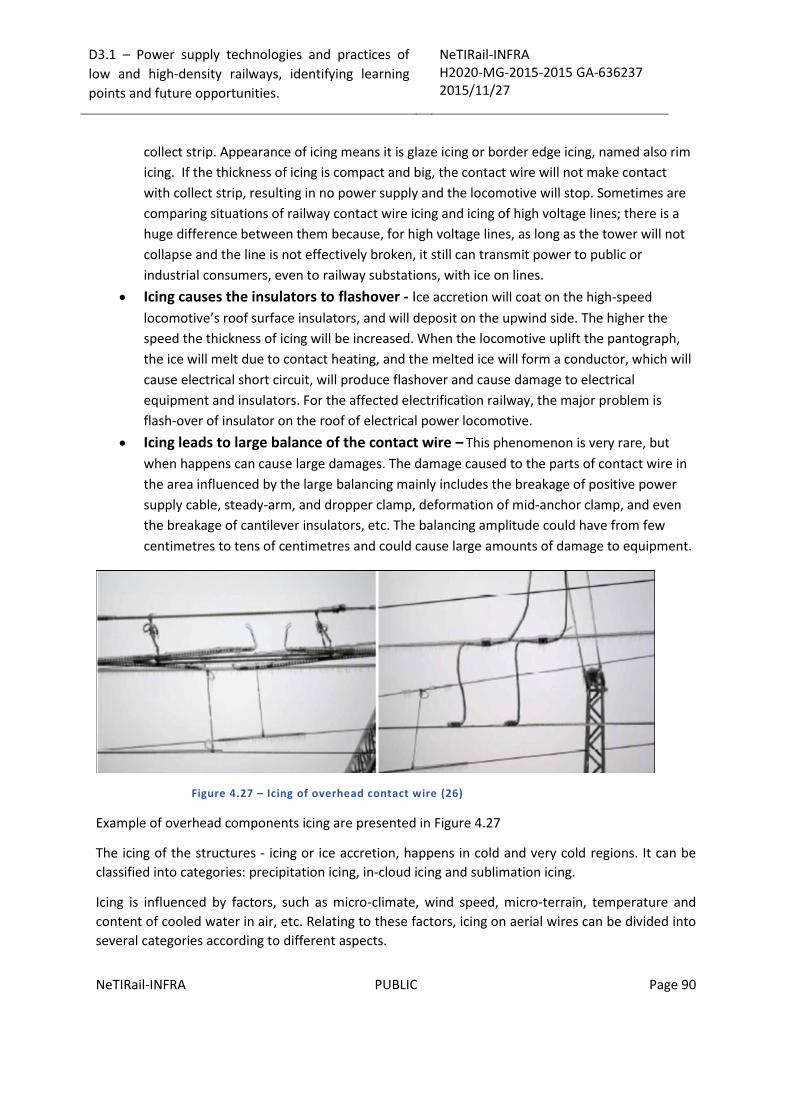
D3.1 – Power supply technologies and practices of
low and high-density railways, identifying learning
points and future opportunities.
NeTIRail-INFRA H2020-MG-2015-2015 GA-636237 2015/11/27
NeTIRail-INFRA PUBLIC Page 90
collect strip. Appearance of icing means it is glaze icing or border edge icing, named also rim
icing. If the thickness of icing is compact and big, the contact wire will not make contact
with collect strip, resulting in no power supply and the locomotive will stop. Sometimes are
comparing situations of railway contact wire icing and icing of high voltage lines; there is a
huge difference between them because, for high voltage lines, as long as the tower will not
collapse and the line is not effectively broken, it still can transmit power to public or
industrial consumers, even to railway substations, with ice on lines.
Icing causes the insulators to flashover - Ice accretion will coat on the high-speed
locomotive’s roof surface insulators, and will deposit on the upwind side. The higher the
speed the thickness of icing will be increased. When the locomotive uplift the pantograph,
the ice will melt due to contact heating, and the melted ice will form a conductor, which will
cause electrical short circuit, will produce flashover and cause damage to electrical
equipment and insulators. For the affected electrification railway, the major problem is
flash-over of insulator on the roof of electrical power locomotive.
Icing leads to large balance of the contact wire – This phenomenon is very rare, but
when happens can cause large damages. The damage caused to the parts of contact wire in
the area influenced by the large balancing mainly includes the breakage of positive power
supply cable, steady-arm, and dropper clamp, deformation of mid-anchor clamp, and even
the breakage of cantilever insulators, etc. The balancing amplitude could have from few
centimetres to tens of centimetres and could cause large amounts of damage to equipment.
Figure 4.27 – Icing of overhead contact wire (26)
Example of overhead components icing are presented in Figure 4.27
The icing of the structures - icing or ice accretion, happens in cold and very cold regions. It can be
classified into categories: precipitation icing, in-cloud icing and sublimation icing.
Icing is influenced by factors, such as micro-climate, wind speed, micro-terrain, temperature and
content of cooled water in air, etc. Relating to these factors, icing on aerial wires can be divided into
several categories according to different aspects.

D3.1 – Power supply technologies and practices of
low and high-density railways, identifying learning
points and future opportunities.
NeTIRail-INFRA H2020-MG-2015-2015 GA-636237 2015/11/27
NeTIRail-INFRA PUBLIC Page 91
Ice classification based on density and appearance:
Glaze: transparent vitreous, unbreakable and strong in texture with density between 0.6 and
0.9 g/cm3, can also be called ice slush or clear ice which covers wires with strong adhesive
power and never easy to shed.
Granular Rime: ivory opaque with density between 0.1 and 0.3 g/cm3, loose and crisp in
texture with air bubble voids inside, sinuous surface and irregular shape.
Crystalline Rime: white crystal with many air bubbles inside, loose and soft in texture with
density between 0.01 and 0.08 g/cm3, weak adhesive power on wires and easy to shed.
Wet Snow: ivory or off white, usually soft in texture with density between 0.1 and 0.7
g/cm3. Wet snow on wires will turn into hard frozen body when the temperature continues
to decrease.
Mixed Rime: ivory, large with many voids, is formed by the alternate freezing of glaze and
rime on wire surface, and the density ranges from 0.2 to 0.6 g/cm3. (26)
Classifications of ice based on formation mechanism:
Precipitation: This type of ice is formed by freezing rain (super cooled water) or snow falling
on the wire surface when atmospheric temperature is around to 00 C. Usually the bigger
drops are correlated with the lower temperature degree. The super cooled degree of little
water drops can be several centigrade, while the degree for fog droplets can even be more
than ten degrees. Once touching the wires, the super cooled water droplets would freeze.
Because the speed of releasing latent heat is slow during the process of freezing, a thin
surface of water would appear on the wire surface, and so the glaze appears. The most
dangerous to aerial wires is the glaze formed by icing precipitation; this is because of its high
density and strong adhesive power. Freezing rain often happens in America, Canada, Russia
China, etc., while icing from the snow covering is more common in Japan and the Europe –
Alps and Carpathians.
Cloud or fog in the air: Frozen ice by these sources mainly depends on humidity, air velocity
etc. This type of icing happens with high frequency in many places and is possible to do
simulation study with artificial weather model, which is one feature of in-cloud icing.
Another is that in-cloud icing can be formed as long as super cooled water drop exists. Small
in size, the fog droplets can release the latent heat quickly when freezing. Thus, it won’t
form a water layer on wire surface but usually produces rime shape ice.
Sublimation: This process forms frost when air water vapours freezes on the surface of
overhead wires, installation surface, etc., and is called crystalline rime. Formed through
sublimation, it is called sublimation icing. Because of its weak adhesion and easy to shed, it
won’t represent danger to the overhead wire. But this type of icing can represent a start
support for glaze, mixed rime and wet snow, etc. and in this way can increases the risk of
danger for railway power supply system.

D3.1 – Power supply technologies and practices of
low and high-density railways, identifying learning
points and future opportunities.
NeTIRail-INFRA H2020-MG-2015-2015 GA-636237 2015/11/27
NeTIRail-INFRA PUBLIC Page 92
The icing of overhead wires is mainly influenced by micro-climate and micro-terrain. The size, rigidity
and shape of the wires may also affect the icing thickness and density.
Micro-climate includes the next factors: temperature, wind speed, wind direction, and liquid water
content in the air (LWC). These parameters are useful in the prediction model of icing. They can be
acquisitioned through specialised sensors and their values can control the flow and heat transfer in
icing and de-icing processes.
Micro-terrain includes next elements: altitude of the wire, topography of the local area, water
presence in the region and water distribution, etc. Their major functions are to affect in heterogenic
way and will cause different icing phenomenon; results can be used in modelling as historical and
statistics range values.
Temperature is the main influencing factor of icing. Generally, the temperature of icing is always
below 00 C, but if it is too cold (below -100 C), icing won’t occur.
If water drops at cooled degree and high quantity, icing would happen even slightly over 00 C, and
this will form dense glaze.
Speed of wind is an important factor of icing because of it characteristics to decrease atmospheric
temperature. It will create ice when the cooled water droplets touch the wire surface. The wind
sends the cooled water drops to the wire surface; the wind speed also affects the heat transfer in
the process of icing.
Therefore, the higher the speed of wind is, the more cooled water drops can touch the wire surface;
the more easily the latent heat released in the process of icing to be lost, and the more icing on the
wire surface.
Direction of wind also has certain influence on icing. The wind direction mainly affects the
effectiveness of super cooled water drop delivery. If the wind direction is perpendicular to the wires,
the delivery is the most effective; if the wind direction is parallel to the wires, the delivery is the
least effective, hence less icing.
Liquid water content (LWC) has an important influence on icing. It will not only influence the speed
of icing but also the types of icing. If LWC is low and diameter of the droplets is small, rime is formed
and icing develops slowly, whereas if LWC is relatively high and diameter of the droplets is relative
large, glaze is formed and icing develops quickly. If the LWC is very high and diameter of the droplets
is very large, rain is formed. (26)
4.2.9 Comparison between icing on contact wires and on aerial network of high-voltage lines:
Structure Differences – High voltage transmission wires related to public electric grid or industrial
network are steel with aluminium core while most contact lines of electrification railway are copper
alloy wires. For this reason, when difference in wire surface, the icing will be different. The contact
line has several points of bearing and a shorter (less than 65m). In this way, the suspension is well
distributed, can be seen as a straight line, that will not twist when will freeze; high voltage

D3.1 – Power supply technologies and practices of
low and high-density railways, identifying learning
points and future opportunities.
NeTIRail-INFRA H2020-MG-2015-2015 GA-636237 2015/11/27
NeTIRail-INFRA PUBLIC Page 93
transmission line is stranded with very long (300m - 500m), which will twist when glaze and icing
occurs and will cause high waves in the wind (see Figure 4.28 and Figure 4.29).
Figure 4.28 – Icing of high-voltage line (26)
Figure 4.29 – Icing of overhead contact wire (26)
Height Differences - There is a big difference in height between electrification railway contact
wires – around 6 m - and high-voltage lines that have heights up to tens of meters. The influence of
wind speed varies and is very important. The speed of surface wind is weaker than that of high-
altitude wind; the icing of contact wire will be weaker than that of high-voltage line under the same
meteorological parameter and geographical factors.

D3.1 – Power supply technologies and practices of
low and high-density railways, identifying learning
points and future opportunities.
NeTIRail-INFRA H2020-MG-2015-2015 GA-636237 2015/11/27
NeTIRail-INFRA PUBLIC Page 94
There are many theoretical models used to predict icing formation, as glaze and rime. These include
the Imai model - based on wet growth process; Lenhard model – a formula to calculate the weight of
the ice; Goodwin model – based on dry growth process; Chaine model - dry growth process, but
shape of the icing is the uneven oval and Makkonen model - considering the existence of ice cycles.
(26)
Conclusions related to ice accretion:
The wind speed has important influence on icing; when the wind speed is higher, the ice will
become high density.
Temperature air increasing leads to increasing ice density but decreasing ice thickness.
Ice type begins to change around -40 C. When the temperature is higher than -40 C, large
mixed glaze ice or glaze ice will form; when the temperature is below -40 C, rime ice will
form.
The type of the ice is influenced and affected by air temperature but not influenced by wind
speed; the wind speed will lead to the increasing of adhesion of the ice to contact wires;
4.3 Modern practices and components selection for new railway electric traction systems
4.3.1 Overview
As definition, power supply systems for railway cover all aspects of the electricity supply, needed for
operation of electric locomotive motors. It consists mainly of technology and infrastructure to
energy conversion at substations, power transmission circuits to supply electrical power to
consumers’ systems; these transport systems can be DC or AC. In the composition of power supply
systems for railway have to be included also fixed structures, measurement and inspection
materials, overhead lines maintenance equipment.
Sending electric power through the overhead line and pantograph introduced nearly 100 years ago
in electric railways and remains basically unchanged as main principles. However, technological
developments have concentrated to increase the current capacity, speed, and safety; nowadays the
current capacity is more than sufficient to drive modern super high-speed trains.
As detailed and structured the overhead contact line system (OCS) comprises overhead contact line,
cantilevers, poles, foundations and return conductors to supply current for use by electric railways.
The overhead contact line (OCL) consists of contact wire, catenary wire, droppers, stitch wires, fixed
points and tensioning devices.
Figure 4.30 illustrates a typical overhead contact line system design with individual poles on both
sides of the tracks. This is the preferred design for main line traffic at all usual voltages and for urban
transportation. The components such as contact line, cantilevers, poles, traction power feeder lines,
return current conductors and rail bonds are shown in this schematic diagram.
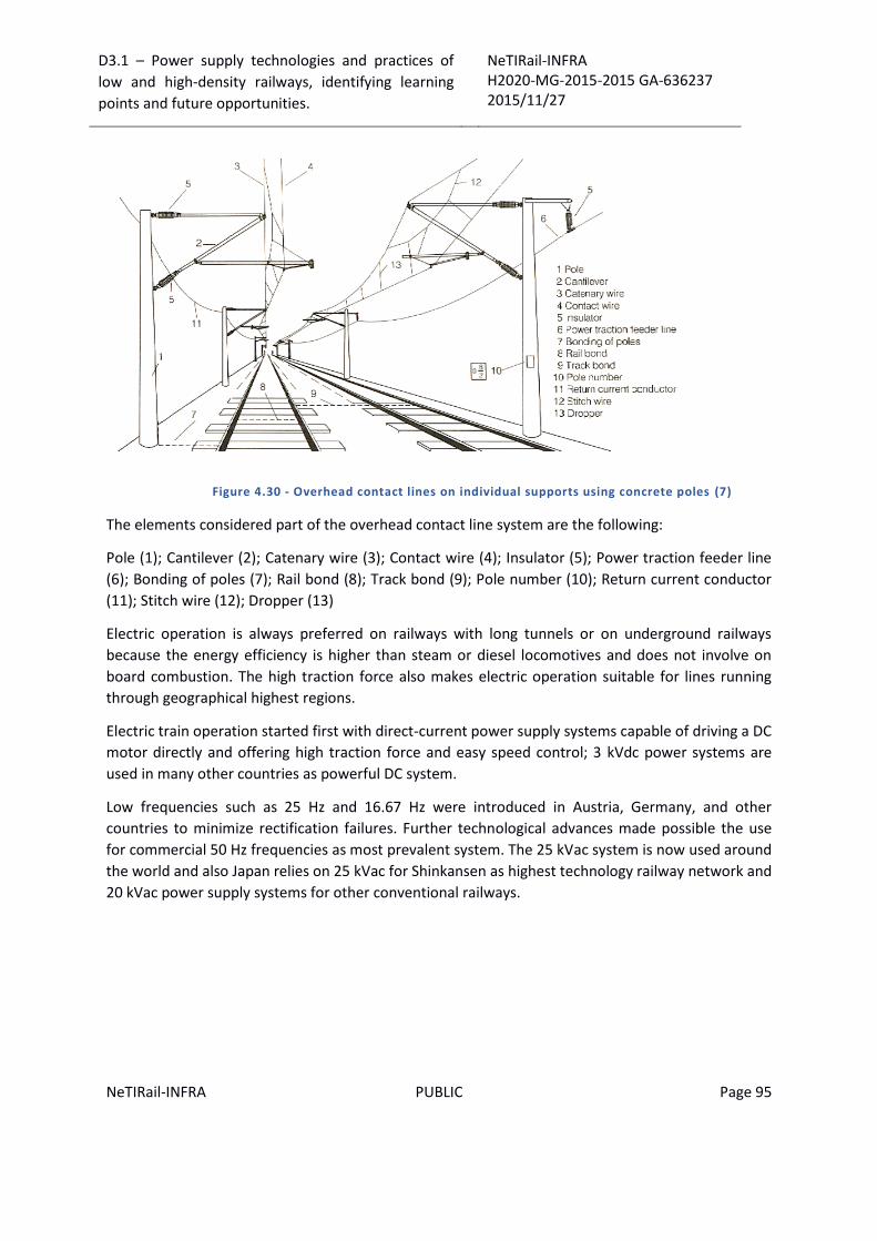
D3.1 – Power supply technologies and practices of
low and high-density railways, identifying learning
points and future opportunities.
NeTIRail-INFRA H2020-MG-2015-2015 GA-636237 2015/11/27
NeTIRail-INFRA PUBLIC Page 95
Figure 4.30 - Overhead contact lines on individual supports using concrete poles (7)
The elements considered part of the overhead contact line system are the following:
Pole (1); Cantilever (2); Catenary wire (3); Contact wire (4); Insulator (5); Power traction feeder line
(6); Bonding of poles (7); Rail bond (8); Track bond (9); Pole number (10); Return current conductor
(11); Stitch wire (12); Dropper (13)
Electric operation is always preferred on railways with long tunnels or on underground railways
because the energy efficiency is higher than steam or diesel locomotives and does not involve on
board combustion. The high traction force also makes electric operation suitable for lines running
through geographical highest regions.
Electric train operation started first with direct-current power supply systems capable of driving a DC
motor directly and offering high traction force and easy speed control; 3 kVdc power systems are
used in many other countries as powerful DC system.
Low frequencies such as 25 Hz and 16.67 Hz were introduced in Austria, Germany, and other
countries to minimize rectification failures. Further technological advances made possible the use
for commercial 50 Hz frequencies as most prevalent system. The 25 kVac system is now used around
the world and also Japan relies on 25 kVac for Shinkansen as highest technology railway network and
20 kVac power supply systems for other conventional railways.

D3.1 – Power supply technologies and practices of
low and high-density railways, identifying learning
points and future opportunities.
NeTIRail-INFRA H2020-MG-2015-2015 GA-636237 2015/11/27
NeTIRail-INFRA PUBLIC Page 96
System Type Worldwide
DC
< 1.5 kV Germany, UK, Switzerland, USA, Japan
1.5 kV – 3 kV (predominant 1.5 kV) France, Spain, Netherlands, Australia, Japan
≥ 3 kV (predominant 3 kV) Russia, Poland, Italy, Spain, South Africa
Single - phase
AC
50 Hz &
60 Hz
< 20 kV France, USA
20 kV Japan
25 kV Russia, France, Romania, Japan, India, China
50 kV USA, Canada, South Africa
25 Hz; 11 kV - 13 kV USA, Austria, Norway
16.67 Hz 11 kV Switzerland
15 kV Germany, Sweden, Switzerland
Three-phase AC Switzerland, France, Japan
Table 4.3 - Railway Electricity Systems Dispersion
4.3.2 Overhead Line Systems
The structure of an overhead line can be seen in Figure 4.31 and consists of individual spans, which
are designed according to the application of the contact line. The contact line is divided into
individual tensioning sections.
Figure 4.31 - Design of a contact line section and a span.
Terminations or tensioning equipment are found at the ends of these sections. The tensioning
equipment maintains the tensile forces in the contact wire and the catenary wire approximately
constant at varying temperatures. The contact line must be designed to satisfy the static, dynamic,
thermal and electrical requirements for each application.

D3.1 – Power supply technologies and practices of
low and high-density railways, identifying learning
points and future opportunities.
NeTIRail-INFRA H2020-MG-2015-2015 GA-636237 2015/11/27
NeTIRail-INFRA PUBLIC Page 97
Overhead line systems have role to transfer electric power from substations to moving vehicles
on the railway; these are necessary for electric motors, lights, air conditioning, etc., The energy used
by locomotives are collected from the overhead line using the pantograph on the vehicle roof. The
pantograph should be in direct and constant contact with the overhead contact wire. Therefore, the
overhead line must always be located within the pantograph range, and the pantograph must always
maintain contact with the overhead line to supply uninterrupted, good-quality power at all times. To
accomplish these conditions, the overhead line system is generally designed with these
requirements:
Should be considered general characteristics generated by speeds at which trains will run.
The height above ground must be uniform as possible to optimize pantograph electrical
power collecting, so entire equipment must have uniform spring forces and rigidity.
Have to be affected by minimum vibration and motion to ensure pantograph passage as
smooth as possible during high-speed running or when strong winds
Need to have enough strength to withstand vibration, corrosion, heat, etc., that means
reliability on operational life.

D3.1 – Power supply technologies and practices of
low and high-density railways, identifying learning
points and future opportunities.
NeTIRail-INFRA H2020-MG-2015-2015 GA-636237 2015/11/27
NeTIRail-INFRA PUBLIC Page 98
Figure 4.32 – Synthetic Layout Overhead Lines of world high speed railways (24)
Figure 4.32 compares the catenary equipment for high-speed trains in different countries. In Japan,
compound catenary equipment consisting of three longitudinal wires is used for Shinkansen, while
simple or stitched catenary equipment is used in Europe. Also, the Italian high-speed line uses twin
catenary equipment to supply the large current for the electrification with 3 kVdc. Compound
catenary systems feature less pantograph vertical motion and less vibrations but larger current
capacity and require a larger number of components, resulting in a more complex design, see Figure
4.33.
Figure 4.33 – Compound overhead line13
13 http://www.aeg-ie.com/englisch/rolling_stock.htm

D3.1 – Power supply technologies and practices of
low and high-density railways, identifying learning
points and future opportunities.
NeTIRail-INFRA H2020-MG-2015-2015 GA-636237 2015/11/27
NeTIRail-INFRA PUBLIC Page 99
Figure 4.34 – Simple catenary equipment14
Simple catenary system is used in Europe and pre sag has role to compensate large vertical motion
of the pantograph (see Figure 4.34). Pre sag means to design feature in which the height of the
contact wire is lower at the centre of the span by an amount equal to around 1/1000 of the span. In
real terms, generally, the contact wire height is 20 or 30 mm lower at the centre of the span than at
supports, suppressing the pantograph vertical motion. This design is effective for the overhead lines
on the French and German high-speed lines which have large amplitude, but is less effective for
overhead lines with small amplitudes like the Italian high-speed line, also for Shinkansen line.
The Naganobound - Shinkansen (Takasaki-Nagano section), which started operations in October
1997, uses the simple catenary overhead equipment; that is commonly for Europe. This system was
chosen for economy because the less-frequent train operation consumes only a small proportion of
the current-carrying capacity. This high speed line uses a 110 mm2 copper - clad steel wire; the wire
tension is 20 kN to resist for the train 260 km/h operating speed. This is a particularly simple
catenary system for high speed operation in Japan.
4.3.2.1 Lateral wave propagation
The most critical constants for the performance of the overhead line, mechanical point of view, are
the weight and tension per unit length. The tension is linked by the push force pantograph against
the contact line. These tension direct influences vertical motion of the overhead line. The values are:
54 kN for Shinkansen and 28 kN to 34 kN for the French and German overhead systems. The Italian
14 http://www.eurobricks.com/forum/index.php?showtopic=76552

D3.1 – Power supply technologies and practices of
low and high-density railways, identifying learning
points and future opportunities.
NeTIRail-INFRA H2020-MG-2015-2015 GA-636237 2015/11/27
NeTIRail-INFRA PUBLIC Page 100
system accepts a total tension of 66 kN because it uses a twin catenary system with a larger wire
size. The pantograph push-up force is roughly 70 N to 80 N for Japan, 130 N to 250 N for France and
Germany, and 200 N to 300 N for Italy. This means France and Germany have overhead contact line
tension amplitude about four times greater than that of Japan. Generally, greater stability results
from smaller overhead line amplitude. It also reduces the fault frequency and damage to
components.
As definition, the square root of the ratio of the contact wire tension to the weight per unit length
represents the velocity of the lateral wave propagating along the wire. This is the most important
parameter in overhead line design. In railway technology, this velocity is called the wave
propagation velocity.
Table 4.4 shows the velocity for wave speed and the ratio of the train speed related to the wave
propagation velocity. Experiments have tested that if the train speed approaches the wave
propagation velocity, the overhead line amplitude and local bending are increased; the contact of
the pantograph and overhead line will be difficult to maintain. When the train speed exceeds 70% to
80% of the wave propagation velocity, risk of pantograph contact loss increases greatly; overhead
line itself can be destroyed.
Item
France Germany Italy Japan
TGV
Southeast
TGV
Catenary type
Stitched and
simple
Simple Stitched and
simple
Twin
stitched and
simple
Heavy
compound
type
Standard span [m] 63 (Stitched
wire 15)
63 65 (Stitched
wire 18)
50
Standard wire height
[m]
4.95 4.95 5.3 4.85 5.0
System height [mm] 1400 1400 1800 1400 1500
Wire
grade
Suspended
Bz 65 mm2
(0.59 kg/m)
Bz 65 mm2
(0.59 kg/m)
Bz11 70 mm2
(0.63 kg/m)
CdCu 153.7
m2 (1.42
kg/m)
St 180 mm2
(1.450
kg/m)
Auxiliary
suspended
Bz 35 mm2 - Bz11 35 mm2
(0.31 kg/m)
(0.30 kg/m) Cu 150
mm2 (1
.375 kg/m)
Contact
wire
CdCu 120
mm2
Cu 150 mm2
(1.33 kg/m)
CuAg Ri 120
mm2 (1.08
kg/m)
CuAg 151.7
mm2 (1.35
kg/m)
Cu 170
mm2 (1
.511 kg/m)
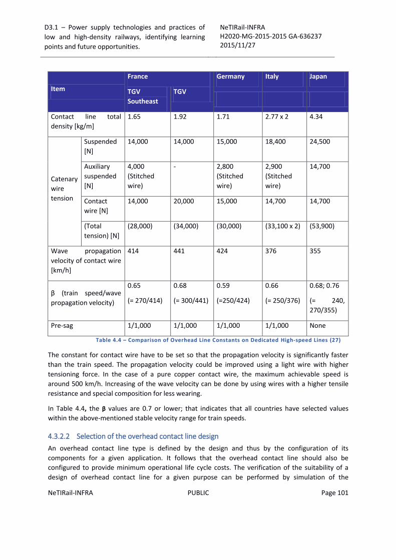
D3.1 – Power supply technologies and practices of
low and high-density railways, identifying learning
points and future opportunities.
NeTIRail-INFRA H2020-MG-2015-2015 GA-636237 2015/11/27
NeTIRail-INFRA PUBLIC Page 101
Item
France Germany Italy Japan
TGV
Southeast
TGV
Contact line total
density [kg/m]
1.65 1.92 1.71 2.77 x 2 4.34
Catenary
wire
tension
Suspended
[N]
14,000 14,000 15,000 18,400 24,500
Auxiliary
suspended
[N]
4,000
(Stitched
wire)
- 2,800
(Stitched
wire)
2,900
(Stitched
wire)
14,700
Contact
wire [N]
14,000 20,000 15,000 14,700 14,700
(Total
tension) [N]
(28,000) (34,000) (30,000) (33,100 x 2) (53,900)
Wave propagation
velocity of contact wire
[km/h]
414 441 424 376 355
β (train speed/wave
propagation velocity)
0.65
(= 270/414)
0.68
(= 300/441)
0.59
(=250/424)
0.66
(= 250/376)
0.68; 0.76
(= 240,
270/355)
Pre-sag 1/1,000 1/1,000 1/1,000 1/1,000 None
Table 4.4 – Comparison of Overhead Line Constants on Dedicated High-speed Lines (27)
The constant for contact wire have to be set so that the propagation velocity is significantly faster
than the train speed. The propagation velocity could be improved using a light wire with higher
tensioning force. In the case of a pure copper contact wire, the maximum achievable speed is
around 500 km/h. Increasing of the wave velocity can be done by using wires with a higher tensile
resistance and special composition for less wearing.
In Table 4.4, the β values are 0.7 or lower; that indicates that all countries have selected values
within the above-mentioned stable velocity range for train speeds.
4.3.2.2 Selection of the overhead contact line design
An overhead contact line type is defined by the design and thus by the configuration of its
components for a given application. It follows that the overhead contact line should also be
configured to provide minimum operational life cycle costs. The verification of the suitability of a
design of overhead contact line for a given purpose can be performed by simulation of the

D3.1 – Power supply technologies and practices of
low and high-density railways, identifying learning
points and future opportunities.
NeTIRail-INFRA H2020-MG-2015-2015 GA-636237 2015/11/27
NeTIRail-INFRA PUBLIC Page 102
interaction between the overhead line and the pantograph or by carrying out a track test. Table 4.5
contains applications for typical overhead contact line designs.
Type Design Properties Application
1
Simple overhead contact line
without continuous catenary
wire, fixed termination or
flexible tensioning, horizontal
registration arrangements
Contact wire height changes
with temperature,
Limited span length and
current carrying capacity
Light rail systems (tramways)
With low electrical load,
sidings on mainline railways,
speed up to 100 km/h
2
Vertical contact line without
stitch wire,
tensioned contact wire,
catenary wire fixed or
tensioned
Contact wire height
independent of temperature,
span lengths up to 80 m are
possible, current-carrying
capacity can be adapted by
selecting suitable catenary
wire and contact wire cross
sections, large variation of
elasticity between mid-span
and support
Tramways with high electrical
load, main-line railways at
speeds up to 120 km/h, two
parallel contact wires are often
employed with DC traction
supplies
3
As (2), but with or without
stitch wire, automatically high
tensioned contact wire and
catenary wire
As (2), however lower
elasticity differences between
mid-span and support
Main-line railways with high
electrical loading and speeds
up to 350 km/h
4
Vertical contact line with
auxiliary catenary wire
automatically tensioned
As (3), however higher
current-carrying capacity and
more uniform elasticity
Main-line railways with very
High electrical loading and very
high speeds
Table 4.5 - Typical applications for types of overhead line system designs
4.3.2.3 Selection of conductor cross sections and tensile forces
The contact wire and catenary wire cross sections are to be kept as small as possible for economic
reasons. They should be designed to satisfy requirements at the lowest investment. The traction
power supply system, the traffic timetable and the route profile determine the magnitude of the
current flowing through the overhead contact lines. There are major differences between the
D3.1 – Power supply technologies and practices of
low and high-density railways, identifying learning
points and future opportunities.
NeTIRail-INFRA H2020-MG-2015-2015 GA-636237 2015/11/27
NeTIRail-INFRA PUBLIC Page 103
conductor cross sections for high density lines and lines with low density of traffic; also, are larger
differences between conventional lines and high speed lines.
4.3.2.4 Selection of span lengths
Long span lengths are desirable in view of keeping investment down. Contact wires that are
displaced by wind from their still air position have to guarantee an uninterrupted power transfer.
Determination of span length must consider the wind loading per unit length for the contact wire
and the catenary wire for the anticipated regional wind velocity. The height of the overhead contact
lines above the surrounding terrain together with maximum regional wind velocity determines the
wind velocity to be applied.
4.3.2.5 Selection of system height
The regular system height, being the distance between the contact wire and the catenary wire at
supports should allow for the installation of minimum design length droppers at the centre of the
span.
The minimum lengths of flexible dropper (LHmin) are dependent upon running speed. Recommended
minimum dropper lengths for design are:
v <= 120 km/h; LHmin = 300mm;
v > 120km/h; LHmin = 500 mm;
If this is not possible, shorter flexible droppers, and finally sliding droppers have to be employed.
These transfer the contact wire lift directly to the catenary wire and, therefore, generate force peaks
in the contact force profile. To respect the minimum dropper length is important in view of dynamic
behaviour. Shorter droppers in combination with inflexible material increase the probability of
dropper failures, especially at higher speeds and larger contact wire lift.
System heights in stations are usually greater than those employed on the interstation line, because
of the installation of section insulators, and the need to avoid electrical clearance problems between
crossing contact lines of different electrical sections, especially under dynamic uplift conditions.
4.3.2.6 Design of contact lines in tunnels
In addition to the general requirements, there is a need to minimise the installation space for tunnel
overhead contact lines in order to keep the overall tunnel cross section as small as possible.
The contact wire height should be kept as low as possible to minimize the tunnel cross section and
the associated construction investment. However, contact wire gradients are not permitted on high-
speed lines, so that the same contact wire heights has priority, as found on the open line sections.
To keep the tunnel cross section low, a low system height should be provided within the tunnel; this
requires shorter span lengths e.g. 50 m. Depending by the operating speed, alternative contact line
equipment are possible, could be used overhead contact lines with elastic or overhead contact rail
systems and with short support intervals, e.g. 10m.
D3.1 – Power supply technologies and practices of
low and high-density railways, identifying learning
points and future opportunities.
NeTIRail-INFRA H2020-MG-2015-2015 GA-636237 2015/11/27
NeTIRail-INFRA PUBLIC Page 104
4.3.2.7 Adoption of contact wire pre-sag
For some designs of overhead contact lines, the contact wire is not threaded at a constant height
above the top of rail. For example, the TGV overhead line for SNCF, the contact wire is provided with
a contact wire pre-sag of 0.1 % of the span length, so that the contact wire is lower at the centre of
the span than at the supports. The provision of pre-sag is based on the premise that the overhead
contact line has a lower resilience at the supports than at mid span, and the pantograph, therefore,
lifts the contact wire at the supports to a lesser degree than at mid span. In order to achieve an
almost constant pantograph operating height during the passage of a train, a pre-sag is provided at
mid span, which should compensate for the difference in lift at the support compared to that at mid
span. The dynamic components of contact wire lift, however, increase with increasing speed and the
pantograph is pressed downwards by the pre-sag at mid span. Tests performed during the
development of the overhead contact lines for the new high-speed line sections at DB showed that a
pre-sag is not necessary for high-speed overhead contact line systems, and can even be negative
from the viewpoint of running characteristics. According to SNCF's experience a pre-sag is also useful
for high-speed contact lines without stitch wires as proven by studies and tests. An initial pre-sag can
also contribute to compensate the effect of wear which could result in a negative sag. When
installing the contact wire, a pre-sag of 0 to 0.05 % of the span length should be aimed at.
A pre-sag can provide running quality for overhead contact line systems up to 200 km/h with their
relatively large elasticity differences along the line, whereby the static behaviour in the interaction
between the overhead line and the pantograph is predominant.
4.3.2.8 Selection of dropper spacing
The catenary wire supports the contact wire via the droppers (hangers). Dependent upon the
contact wire tensile force, the dropper intervals determine the contact wire sag between droppers.
To limit this sag, the dropper intervals should be less than 12 m. The dropper intervals are also
chosen with the objective of allowing contact between the contact wire and the track after a contact
wire failure, thus activating the tripping of the section feeder circuit breaker. However, this safety
requirement will be satisfied even if the dropper intervals are less than double the contact wire
height and the contact wire fails in the middle of two droppers, since the adjacent droppers also fail,
allowing the contact wire to make contact with the track, creating a short circuit.
Following consideration of these aspects, dropper intervals between 5 m and 12 m have been used.
4.3.2.9 Using of a stitch wire
In the case of contact lines with a fixed catenary wire, stitch wires compensate for changes in
contact wire height at the supports and at mid-span caused by varying temperatures. In the case of
automatically tensioned contact and catenary wires the stitch wires equalise the elasticity at the
supports and in mid span. The vertical movement of the contact point where the collector strip
touches the contact wire should be as low as possible within a span. Low differences in the elasticity
result in nearly constant contact point height and a higher current transmission quality. According to
the TSI Energy the difference between the highest and lowest dynamic contact point within a span
should be:

D3.1 – Power supply technologies and practices of
low and high-density railways, identifying learning
points and future opportunities.
NeTIRail-INFRA H2020-MG-2015-2015 GA-636237 2015/11/27
NeTIRail-INFRA PUBLIC Page 105
In the case of contact lines for AC lines:
80 mm for line design speeds of 250 km/h and above;
100 mm for line design speeds below 250 km/h;
In the case of contact lines for DC lines:
80 mm for line design speeds of 250 km/h and above;
150 mm for line design speeds below 250 km/h;
The compliance of the contact wire height variation within a span has to be verified on the installed
system.
Elasticity differences between the support and at mid span result in varying contact forces and
uneven wear of the contact wire
The lengths and tensile forces of the stitch wires are the results of optimisation processes, whose
objectives were to achieve, as far as possible, the same elasticity near the support as at mid span.
When commissioning the AC contact line type Sicat H1.0 as installed on the high-speed line HSL Zuid
in the Netherlands, the maximum difference in the height of the contact point was recorded as 18
mm at 330 km/h.
SNCF used stitch wires on the Paris-Lyon high-speed line and experienced that they were difficult to
be installed and maintained. Therefore, the contact lines for the other high-speed lines in France
were designed without stitch wires.
4.3.2.10 Selection of tensioning section length
The temperature range of the overhead contact line, the operating range of the tensioning
mechanism, the variation of the contact wire tensile force along the section, and the permitted
tolerances for the contact wire stagger and contact wire height, determine the tensioning section
length, (see Figure 4.35). Higher tensile forces require longer weight stacks and, therefore, reduce
the operating range.
Overhead contact lines are normally automatically tensioned at both ends. Tensioning section
lengths shorter than 750 m that are automatically tensioned at one end and rigidly anchored at the
other, are adopted in station areas and at special locations on the interstation track. Single ended,
tensioning sections offer advantages especially for contact lines in transitions between open track
and a tunnel. There, longitudinal displacements of the contact line and loadings on the midpoint
anchor can occur. These are caused by different ambient temperatures in the tunnel and in the
open, when double-ended flexibly tensioned contact lines are adopted. These displacements are
avoided by single ended tensioning sections.

D3.1 – Power supply technologies and practices of
low and high-density railways, identifying learning
points and future opportunities.
NeTIRail-INFRA H2020-MG-2015-2015 GA-636237 2015/11/27
NeTIRail-INFRA PUBLIC Page 106
Figure 4.35 - Example of operating of the tensioning device (7)
Mechanical mid points, fixed anchor points or other kind of restraints should be used in a tensioning
section length of an overhead contact line that is tensioned automatically at both ends, to ensure
the conductors do not migrate towards both ends of the tensioning section length with changes in
the loading conditions. This may be provided for by the installation of an anchoring arrangement at
approximately the midpoint of the tensioning section length or at such a location which balances the
along track forces at the midpoint. Midpoint anchors restrict the travel of the contact line during
temperature variations and after failing of contact wire, catenary wire, or contact line.
The design of the catenary wire fixed point takes into account the different tension loads of either
the catenary wire or the contact wire. The highest value should be applied. The fixed point for
cantilevers should be designed to prevent their movement. For head spans, measures should be
taken to ensure the upper cross span wires can withstand the required longitudinal load. Also,
several adjacent head spans may act as the fixed point.
If a contact wire fixed point is required, this can be achieved in several ways. For example, the
contact wire is connected to the catenary wire by a conductor installed close to the catenary wire
fixed point. Thus, the contact wire is fixed in its position along the track. The design of the contact
wire fixed point should take into account the difference of the operating tensioning forces of the
contact wire on both sides of the fixed points.
The midpoint anchor fixes two-ended automatically terminated overhead contact lines. Two types of
midpoint designs are considered, those with a hinged tubular cantilever and those in cross spans.
For cantilever designs, a midpoint anchor manufactured from bronze or steel conductors fixes both
sides of the catenary wire support. The stabilisation of the midpoint anchors is performed by the
neighbouring poles, which are often provided with anchors. The contact wire is anchored to the
catenary wire on both sides of the midpoint to ensure the conductors do not migrate. The cross-
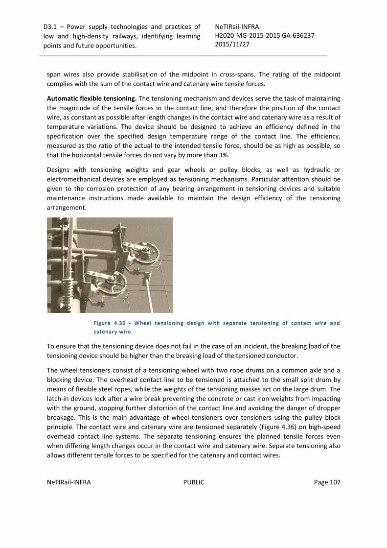
D3.1 – Power supply technologies and practices of
low and high-density railways, identifying learning
points and future opportunities.
NeTIRail-INFRA H2020-MG-2015-2015 GA-636237 2015/11/27
NeTIRail-INFRA PUBLIC Page 107
span wires also provide stabilisation of the midpoint in cross-spans. The rating of the midpoint
complies with the sum of the contact wire and catenary wire tensile forces.
Automatic flexible tensioning. The tensioning mechanism and devices serve the task of maintaining
the magnitude of the tensile forces in the contact line, and therefore the position of the contact
wire, as constant as possible after length changes in the contact wire and catenary wire as a result of
temperature variations. The device should be designed to achieve an efficiency defined in the
specification over the specified design temperature range of the contact line. The efficiency,
measured as the ratio of the actual to the intended tensile force, should be as high as possible, so
that the horizontal tensile forces do not vary by more than 3%.
Designs with tensioning weights and gear wheels or pulley blocks, as well as hydraulic or
electromechanical devices are employed as tensioning mechanisms. Particular attention should be
given to the corrosion protection of any bearing arrangement in tensioning devices and suitable
maintenance instructions made available to maintain the design efficiency of the tensioning
arrangement.
Figure 4.36 - Wheel tensioning design with separate tensioning of contact wire and
catenary wire
To ensure that the tensioning device does not fail in the case of an incident, the breaking load of the
tensioning device should be higher than the breaking load of the tensioned conductor.
The wheel tensioners consist of a tensioning wheel with two rope drums on a common axle and a
blocking device. The overhead contact line to be tensioned is attached to the small split drum by
means of flexible steel ropes, while the weights of the tensioning masses act on the large drum. The
latch-in devices lock after a wire break preventing the concrete or cast iron weights from impacting
with the ground, stopping further distortion of the contact line and avoiding the danger of dropper
breakage. This is the main advantage of wheel tensioners over tensioners using the pulley block
principle. The contact wire and catenary wire are tensioned separately (Figure 4.36) on high-speed
overhead contact line systems. The separate tensioning ensures the planned tensile forces even
when differing length changes occur in the contact wire and catenary wire. Separate tensioning also
allows different tensile forces to be specified for the catenary and contact wires.

D3.1 – Power supply technologies and practices of
low and high-density railways, identifying learning
points and future opportunities.
NeTIRail-INFRA H2020-MG-2015-2015 GA-636237 2015/11/27
NeTIRail-INFRA PUBLIC Page 108
Figure 4.37 - Jointed tensioning device with articulated lever.
Combining of the contact wire and the catenary wire with the same tensioning device is shown in
Figure 4.37 and has the disadvantage that after rupture of either the contact wire or the catenary
wire the wheel tensioner does not always latch-in as a result of the articulated lever. This can result
in the intact part of the contact line being tensioned with a doubled tensile force.
Figure 4.38 shows a tensioning device with compact design.
Figure 4.38 - Tensioning devices with compact design (Siemens AG)
Pulley tensioners operate on the pulley block principle. The weight force is transmitted to the
contact line via several pulley wheels as a horizontal tensile force, as shown in Figure 4.39. The
efficiency of these tensioning devices should be more or equal than 97%. Figure 4.39 shows such a
tensioning device designed by SNCF as used on the Paris-Strasbourg line.
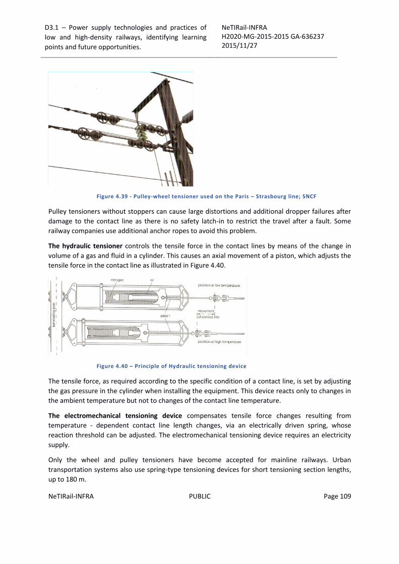
D3.1 – Power supply technologies and practices of
low and high-density railways, identifying learning
points and future opportunities.
NeTIRail-INFRA H2020-MG-2015-2015 GA-636237 2015/11/27
NeTIRail-INFRA PUBLIC Page 109
Figure 4.39 - Pulley-wheel tensioner used on the Paris – Strasbourg line; SNCF
Pulley tensioners without stoppers can cause large distortions and additional dropper failures after
damage to the contact line as there is no safety latch-in to restrict the travel after a fault. Some
railway companies use additional anchor ropes to avoid this problem.
The hydraulic tensioner controls the tensile force in the contact lines by means of the change in
volume of a gas and fluid in a cylinder. This causes an axial movement of a piston, which adjusts the
tensile force in the contact line as illustrated in Figure 4.40.
Figure 4.40 – Principle of Hydraulic tensioning device
The tensile force, as required according to the specific condition of a contact line, is set by adjusting
the gas pressure in the cylinder when installing the equipment. This device reacts only to changes in
the ambient temperature but not to changes of the contact line temperature.
The electromechanical tensioning device compensates tensile force changes resulting from
temperature - dependent contact line length changes, via an electrically driven spring, whose
reaction threshold can be adjusted. The electromechanical tensioning device requires an electricity
supply.
Only the wheel and pulley tensioners have become accepted for mainline railways. Urban
transportation systems also use spring-type tensioning devices for short tensioning section lengths,
up to 180 m.
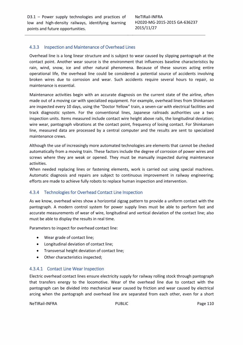
D3.1 – Power supply technologies and practices of
low and high-density railways, identifying learning
points and future opportunities.
NeTIRail-INFRA H2020-MG-2015-2015 GA-636237 2015/11/27
NeTIRail-INFRA PUBLIC Page 110
4.3.3 Inspection and Maintenance of Overhead Lines
Overhead line is a long linear structure and is subject to wear caused by slipping pantograph at the
contact point. Another wear source is the environment that influences baseline characteristics by
rain, wind, snow, ice and other natural phenomena. Because of these sources acting entire
operational life, the overhead line could be considered a potential source of accidents involving
broken wires due to corrosion and wear. Such accidents require several hours to repair, so
maintenance is essential.
Maintenance activities begin with an accurate diagnosis on the current state of the airline, often
made out of a moving car with specialized equipment. For example, overhead lines from Shinkansen
are inspected every 10 days, using the "Doctor Yellow" train, a seven-car with electrical facilities and
track diagnostic system. For the conventional lines, Japanese railroads authorities use a two
inspection units. Items measured include contact wire height above rails, the longitudinal deviation;
wire wear, pantograph vibrations at the contact point, frequency of losing contact. For Shinkansen
line, measured data are processed by a central computer and the results are sent to specialized
maintenance crews.
Although the use of increasingly more automated technologies are elements that cannot be checked
automatically from a moving train. These factors include the degree of corrosion of power wires and
screws where they are weak or opened. They must be manually inspected during maintenance
activities.
When needed replacing lines or fastening elements, work is carried out using special machines.
Automatic diagnosis and repairs are subject to continuous improvement in railway engineering;
efforts are made to achieve fully robots to replace human inspection and intervention.
4.3.4 Technologies for Overhead Contact Line Inspection
As we know, overhead wires show a horizontal zigzag pattern to provide a uniform contact with the
pantograph. A modern control system for power supply lines must be able to perform fast and
accurate measurements of wear of wire, longitudinal and vertical deviation of the contact line; also
must be able to display the results in real time.
Parameters to inspect for overhead contact line:
Wear grade of contact line;
Longitudinal deviation of contact line;
Transversal height deviation of contact line;
Other characteristics inspected;
4.3.4.1 Contact Line Wear Inspection
Electric overhead contact lines ensure electricity supply for railway rolling stock through pantograph
that transfers energy to the locomotive. Wear of the overhead line due to contact with the pantograph can be divided into mechanical wear caused by friction and wear caused by electrical
arcing when the pantograph and overhead line are separated from each other, even for a short

D3.1 – Power supply technologies and practices of
low and high-density railways, identifying learning
points and future opportunities.
NeTIRail-INFRA H2020-MG-2015-2015 GA-636237 2015/11/27
NeTIRail-INFRA PUBLIC Page 111
period of time. Because of these adverse events there is a risk that the contact line to break, if the
wear exceeds a certain limit.
To prevent this event that is extremely costly and dangerous for the entire railway network that
includes that segment, it is essential that the inspection and maintenance of the electric supply
system to be done before reaching this destructive limit.
4.3.4.2 Contact Line Deviation Inspection
The overhead line is in direct contact with the pantograph device; if this contact is limited to a small
area relative to the pantograph, this part of the pantograph will be worn in accentuated grade. To
prevent concentrated wear in a certain area and thus reduce the life of the pantograph, by fixing
overhead line from the supporting pillars will create a horizontal zigzag pattern; in this way will
ensure even wear on contact with the pantograph.
This technique produces a supplementary risk, if overhead line exceeds the pantograph length and
passes beyond the edge, then the line will be caught and blocked on the pantograph edge and it will
break. This risk can be greatly reduced if will be set a safe limit for the horizontal zigzag line of the
contact, bellow the smallest length of a pantograph that cross that section. Obviously this measure
must be accompanied by a scheduling program of inspections and maintenance that should confirm
that this limitation is not exceeded in operational time.
4.3.4.3 Height Inspection
In case of overhead power supply lines there are events as length changes: stretching or contracting;
these situations are associated with temperature changes as seasons changing but also from day to
night. Besides the rapid wearing contact lines these phenomena cause changes in longitudinal
profile lines and changes in their height.
The risk that arises is to cause jumps and frequently disconnection between overhead contact line
and pantograph due contact voltage changes in the distance between the two supporting pillars.
This is why inspections for electrical infrastructure, along the railway, have to include in the protocol
also checking the real height of the contact line. Because of the interaction characteristics between
pantograph and overhead line, these measures needed to be carried out under real working
conditions.
4.3.5 Future Development
Maintenance and inspection activities are becoming increasingly importance with increasing travel
speed on railway networks. The current trend of increasing safety of passenger transportation
makes these activities to gain an even greater importance. Inspection activities are the first step in
establishing the needed maintenance. If these checks are accurate, it can intervene only at times
when needed. Thus, substantial savings can be made with both the materials and components that
need replacing but also reducing downtime for passenger traffic congested segments.
In the near future it is anticipated that the frequency of inspections will be higher because the
request railway infrastructure will be higher.

D3.1 – Power supply technologies and practices of
low and high-density railways, identifying learning
points and future opportunities.
NeTIRail-INFRA H2020-MG-2015-2015 GA-636237 2015/11/27
NeTIRail-INFRA PUBLIC Page 112
At present special vehicles are used for regular inspections; these vehicles contain special equipment
that makes the evaluation of the functionality and wear of the railways.
Hitachi High-Technologies Corporation has developed various track inspection and overhead contact
line inspection systems that use the technologies described above. For example, a top technology
for inspections is “Doctor Yellow”- car inspection for Shinkansen line. The inspection cars for use on
the Tokaido and Sanyo Shinkansen consist of a 7-car configuration. Each car is completed with a line
of inspection equipment. With these cars a total of 25 different railway track inspection
measurements are performed, including noise and axle-box accelerations. The overhead contact line
inspection system, meanwhile, performs a total of 13 measurements at 5 cm intervals. Inspection
can be performed at speeds similar to those used by regular high speed train services (270 km/h).
Figure 4.41 – Railway Inspection Train Class 923, for Shinkansen Lines
A theory gaining credibility is to fit the inspection systems to the trains used for commercial service,
so that measurements can be performed during normal operation. In this kind of solution, Hitachi
High-Technologies Corporation has already developed systems for railway track inspection, and can
be mounted on the commercial vehicles and is working, even on high speed travel.

D3.1 – Power supply technologies and practices of
low and high-density railways, identifying learning
points and future opportunities.
NeTIRail-INFRA H2020-MG-2015-2015 GA-636237 2015/11/27
NeTIRail-INFRA PUBLIC Page 113
5 Power supply systems for existing infrastructure and components
Existing power supply systems, specific for railway infrastructure from partners will be presented.
This includes technical and technological performance related to the railway lines from partner’s
countries, as generalities and practice, and also, it includes the list of case study lines adopted by
NeTIRail-INFRA project and presented in detail.
5.1 Technical characteristics and performance for power supply systems used in United Kingdom
Network Rail has approximately 8000km of OLE (Overhead Line Equipment) electrified AC routes and
4800km of DC electrified tracks. Energy consumption per km of route was mostly on the DC systems
rather than AC during last year.
5.1.1 25kV AC Overhead line
The majority of NR AC traction system is 25kV OLE which is installed on WCML (West Coast Main
Line), ECML and the suburban areas of Glasgow, Leeds, Birmingham & Anglia, including:
• HV Transformer substation (nominal 132/25kV or 400/25.0.25kV);
• Feeder station and along track distribution buildings;
• Mid-Point distribution buildings with neutral sections;
• OLE contact wire and catenary;
• OLE structures, associated track bonds;
• The ECR and SCADA system which control the status of ac and dc circuit breakers, and other
remote operated devices.
The rail return system induces currents which may interfere with the track circuit signalling systems,
when the load of the traction system goes up, the voltage induced into telecoms circuit increases.
In order to boost the return current into the return conductor, booster transformers were installed;
their vicinity to the OLE provides an electric field cancellation effect. Therefore, more than 85% of
the ac network is equipped by booster transformers.
However, booster transformers decrease system capacity by imposing impedance in the electrical
system. To retrofit existing infrastructure, autotransformer technology has been developed by
Network rail, which successfully omits the system impendence. Besides, adding an anti-phase
conductor, increases the transmission voltage as twice as much and improves the efficiency further.
(28)
D3.1 – Power supply technologies and practices of
low and high-density railways, identifying learning
points and future opportunities.
NeTIRail-INFRA H2020-MG-2015-2015 GA-636237 2015/11/27
NeTIRail-INFRA PUBLIC Page 114
5.1.2 750V DC Third rail
This traction system is based on a nominal 750 V, top contact, and third rail system. Over 4800 km of
railway tracks of south of London, plus North London Line, Northern City Lines, Euston to Watford
and Mersey-Rail are powered with this system. The third rail system include the following major
parts:
• The 3-phase high voltage AC Grid supply points
• The 3-phase high voltage AC distribution cables and switching stations
• The DC distribution track paralleling huts and substations including the transformer rectifiers
• The ETE (Electrical Transformer Equipment) and associated return current equipment, like
impedance bonds.
• The ECR and SCADA system which control the status of AC and DC circuit breakers, and other
remote operated devices.
Track paralleling and substation huts are installed every 2-5km through the electrified route.
As the power requirements have increased a number of TPHs (Track paralleling huts) have been
converted to SS (substation huts) resulting in double end fed sections.
Around 370 DC SS and 260 TPH are used to protect the ETE by means of circuit breakers which allow
most roads to be independently controlled.
The loop impedance of the electrical sections has a significant effect on overall system capability.
Originally 100 & 106 lb/yd steel conductor was installed, however since 1960’s the policy changed to
use 150 lb/yd steel rail. Similarly running rails sizes increased from 95 and 109 lb/yd to 113 lb/yd and
recently UIC 60.
The return system which currently been used are available for running rails and are cross-bonded
around 800m, to reduce the impedance of the system by letting the current sharing. To have
continuity in dc traction return current, impedance bonds are used while keeping segregating of the
ac track circuits. Loop impedance varies significantly as the lengths, conductors/ running rails, plus
the number of running rails are varying. (28)

D3.1 – Power supply technologies and practices of
low and high-density railways, identifying learning
points and future opportunities.
NeTIRail-INFRA H2020-MG-2015-2015 GA-636237 2015/11/27
NeTIRail-INFRA PUBLIC Page 115
Figure 5.1 - Southern Circuit Breaker Impedance Settings
5.1.3 New Equipment
By increasing the number of trains utilizing the WCML as well as the introduction of faster services
between major stations, the current OLE system/equipment will get instantly close to its maximum
electrical load capacity.
To provide a safe and reliable railway as part of Network Rail’s commitment in the 21st Century and
to meet future increases/demand for rail services on the WCML, updating the system is required.
The solution was an autotransformer (AT) arrangement, in the UK and EU robust electrical supply on
the WCML has been provided by successful installation and operation of this arrangement, which
meets today’s requirements and increases further capacity for the future
The classic existing OLE system and the AT system are nearly identical; but the introduction of the AT
system added the following: Two single 400mm2 aluminium ‘along track conductors’, one on each
side of the railway which form the ATF. They are typically positioned at high level on the back or
inside of each structure

D3.1 – Power supply technologies and practices of
low and high-density railways, identifying learning
points and future opportunities.
NeTIRail-INFRA H2020-MG-2015-2015 GA-636237 2015/11/27
NeTIRail-INFRA PUBLIC Page 116
Figure 5.2 Typical ATF arrangement
Notes: the approximate placement of the ATF, which is dependent on the type of OLE structure, is
shown by Red line, Booster Transformers have been removed. Return conductor removed. Existing
contact wire also is illustrated by black line
Figure 5.3 Autotransformer system 15
5.1.4 Mileages of the different systems in the UK 16
The length of electrified track is measured in kilometres in the below bands:
Overhead line at 25 kVac.
Overhead line at 1.5kVdc.
Third rail 650 Vdc/ 750Vdc.
The length of running track and loops are considered in the measurement; however, the sidings and
depots are excluded.
15 Ref: Estimation of electrical losses in Network Rail Electrification Systems V1.0, 20.01.10
16 Ref: Annual Return 2013

D3.1 – Power supply technologies and practices of
low and high-density railways, identifying learning
points and future opportunities.
NeTIRail-INFRA H2020-MG-2015-2015 GA-636237 2015/11/27
NeTIRail-INFRA PUBLIC Page 117
Lengths of track with dual electrification are separately taken into account. In addition, earthed line
which is not energized is considered as non–electrified.
For England, Wales, Scotland and the whole network, electrification capabilities are listed in Table
5.1 to Table 5.3 also the breakdown by operating route for 2012/13 compared to previous years
Based on the line speed capability measure’s report, the alterations of Network size mainly cause
the changes of electrification data. An error was made with the AC OHL electrified track kilometres
reported for Scotland in 2011/12. The number reported should have been 1,495 kilometres. This has
now been corrected.
In 2012/13, additional 19km of electrified reported track were completed at Paisley Canal (9km) and
Paisley Corridor (10km). Because of double tracking at Tanners Hill Flydown, the total kilometres of
DC electrified track has gone up in Kent and the Route Asset Managers need to update their data
throughout the year to consider some of these changes.
Table 5.1 - Electrification capacity (km of electrified track) England & Wales
Table 5.2 Electrification capacity (km of electrified track) Scotland

D3.1 – Power supply technologies and practices of
low and high-density railways, identifying learning
points and future opportunities.
NeTIRail-INFRA H2020-MG-2015-2015 GA-636237 2015/11/27
NeTIRail-INFRA PUBLIC Page 118
Table 5.3 Electrification capacity (km of electrified track) Network -wide
5.1.5 Regenerative braking 17
Conventional mechanical disc brakes, electrical braking without regeneration and electric
regenerative braking are types of braking systems commonly used in modern electric and diesel-
electric passenger rolling stock.
Regenerative braking systems decreases the net energy consumption, and it is assumed as a cost-
effective system for the train operators. The regenerative braking system contains a discount to the
modelled traction electricity charge. The available discounts are listed in Table 4.
Table 5.4 Regenerative braking discounts in CP4
Comparing a train with a bicycle provides a better understanding why for regenerative braking is
needed and how it works. Both cases need more energy to start off or in times of accelerating or
climbing, but less effort is required to keep pace on level ground. On downhill sections, both cases
consume negligible energy and they need to apply the brakes to lower speed by friction and
attenuation of extra energy as heat form.
Dynamo lighting which is used in many bicycles, is a small electricity generator powered through the
wheels. Dynamo lighting creates more loads and causes extra energy to speed up. Similarly, in a train
with regenerative braking system when it needs to slow down, the operation of the electric motors
will reverse, so that they generate power rather than using it. The power reduces the momentum of
the train to such an extent that it will stop the train.
17 Ref: Traction electricity consultation – Sep 2012

D3.1 – Power supply technologies and practices of
low and high-density railways, identifying learning
points and future opportunities.
NeTIRail-INFRA H2020-MG-2015-2015 GA-636237 2015/11/27
NeTIRail-INFRA PUBLIC Page 119
A measure of the effectiveness of regenerative braking is that in slippery conditions, it is capable of
causing the wheels to skid in the same way that over application of a mechanical brake will cause the
wheels to lock and slide.
The electrical power exported from the train feeds back into the electricity traction network where it
will either be used by another train nearby that is drawing power, or dissipated through network
losses or, in the case of the AC network, fed back into the national grid system, if the network
transformers allow it. As an alternative, it is also technically feasible to store some of this surplus
energy either on board the train or line-side in batteries or fly wheels.
5.1.6 The regenerative braking discount
There was little financial motive to invest in regenerative braking during the decades of relatively
cheap energy. Environmental issues become more important by increasing the energy prices, the
viability of regenerative braking increases.
However, installation of regenerative braking on new trains was still expensive for train operators.
Train operators were proposed discount in the modelled traction electricity charges for trains
equipped with regenerative braking to encourage the installation of regenerative braking. Since local
commuter trains stop more they would use their regenerative braking more frequently compared to
inter-city trains and return more power to the network. Based on route type and some number of
assumptions, which influence the amount of regenerated power, the regenerative braking discount
varies which did not take account of the impact of the different variables. Historically this was not a
major concern, as any imbalance due to these assumptions between the modelled and actual
consumption was resolved through the annual volume wash-up.
It is important to revisit the way we encourage the use of regenerative braking for operators; since
more operators fit meters to their trains. Based on information gathered from metered operators
Virgin and London Midland the current AC regenerative braking discounts for modelled operators
are in approximately the right range. Similarly, a very small sample of metered data from Southern
Trains shows that the average regenerated energy, as an average percentage of the gross
consumption the regenerated energy was between 16% and 20%. This suggests that the current 15%
discount offered is broadly appropriate; it seems that this data is robust enough to see changing the
current levels.
5.1.7 Factors affecting regeneration
An advantage of moving trains at speed is their low rolling resistance and the disadvantage occurs
when trying to stop a high speed train. A key factor in braking performance is rail adhesion;
therefore, avoid sliding in poor conditions such as ice or leaves, drivers can override the regenerative
braking. This manual intervention means there is no control or check that regenerative braking is in
service even if installed.
Based on train designing and the blending of mechanical braking with regenerative braking, the level
of deceleration and regeneration varies. Some train designs operate friction and electric braking
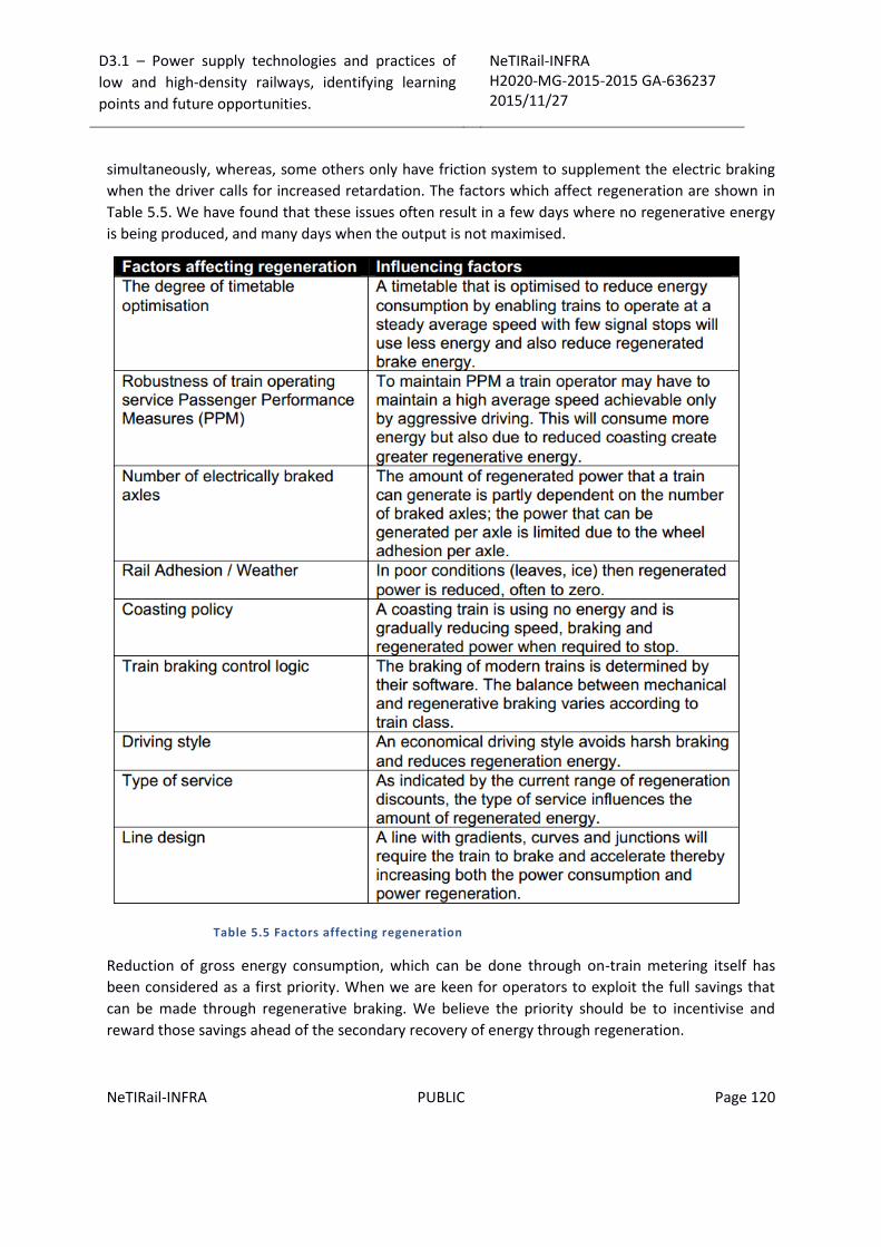
D3.1 – Power supply technologies and practices of
low and high-density railways, identifying learning
points and future opportunities.
NeTIRail-INFRA H2020-MG-2015-2015 GA-636237 2015/11/27
NeTIRail-INFRA PUBLIC Page 120
simultaneously, whereas, some others only have friction system to supplement the electric braking
when the driver calls for increased retardation. The factors which affect regeneration are shown in
Table 5.5. We have found that these issues often result in a few days where no regenerative energy
is being produced, and many days when the output is not maximised.
Table 5.5 Factors affecting regeneration
Reduction of gross energy consumption, which can be done through on-train metering itself has
been considered as a first priority. When we are keen for operators to exploit the full savings that
can be made through regenerative braking. We believe the priority should be to incentivise and
reward those savings ahead of the secondary recovery of energy through regeneration.

D3.1 – Power supply technologies and practices of
low and high-density railways, identifying learning
points and future opportunities.
NeTIRail-INFRA H2020-MG-2015-2015 GA-636237 2015/11/27
NeTIRail-INFRA PUBLIC Page 121
Regenerated energy as well as the gross energy consumption are measured by on-train meters.
Therefore, operators using on-train metering are charged based on metered energy consumption
net of any regenerated power returned to the rail network. This net consumption is then uplifted to
take account of losses.
5.1.8 Quantifying and reducing electrical losses 18
5.1.8.1 AC network
Train B will use up the power which is regenerated by another motoring train A nearby. The short
distance between the trains causes little loss in transferred power and in all probability much less
loss than had train B been supplied by the normal feed.
If there is no other train to consume energy which is regenerated by train A, the surplus energy will
return to the National Grid through the normal grid supply point. In this case, the cost of supply
losses will not be incurred by the train operator; the cost of losses will return for the regenerated
and it will pass through to the volume wash-up and be shared by all parties in that ESTA who are
subject to the year-end volume wash-up.
5.1.8.2 DC network
In the case that there is another motoring train B near train A which regenerates energy, then train B
will consume the regenerated power. Because of short distance little loss will take place in
transferring the power and in all probability much less loss than had train B been supplied by the
normal feed.
However, if train A regenerates energy while there is no other train to use this energy up, the extra
energy cannot be taken back to the National Grid through the normal grid supply point without the
installation of prohibitively expensive inversion equipment. Therefore, the regenerated energy is
leaked and produces heat. Under this scenario, the train operator will not incur the cost of losses in
supply and return for the regenerated energy; all parties in that ESTA are subject to the year-end
volume wash-up and they will share the cost of these losses, which will pass through to the volume
wash-up. As a result, in both the AC and DC networks, overall energy consumption will be decreased
and the current flowing in the electrification system will be increased by regenerative braking
system; therefore, electrification losses will rise. Given the scenarios described above, it is apparent
that there is difference between gross energy consumption loss and energy regenerated loss.
DC regenerative braking systems have to be introduced on all DC electrified routes in Wessex, Sussex
and Kent. The reduction of electric current for traction (EC4T) consumption, reductions in energy
costs and consequent improvement in industry energy efficiency will be achieved through using this
technology. In this modernisation project, also the nominal system voltage has been increased to
750V across the three routes, which makes marginally increment of the available traction supply
capacity.
18 Ref: Traction electricity consultation – Sep 2012; Ref: CP5 Enhancements Delivery Plan

D3.1 – Power supply technologies and practices of
low and high-density railways, identifying learning
points and future opportunities.
NeTIRail-INFRA H2020-MG-2015-2015 GA-636237 2015/11/27
NeTIRail-INFRA PUBLIC Page 122
5.1.8.3 Scope of works
In Wessex, Sussex and Kent routes DC regenerative braking is now in operation and no further work
is required to meet this obligation. To enable the increase of Network Rail system voltage without
risk to LUL rolling stock and systems, Segregation of 660V DC traction supplies to the LUL Waterloo &
City line from Network Rail Infrastructure need be accomplished. The circuit breakers will also have
to be modified to raise traction supply outputs on all inner London routes to 750V DC nominal in
Wessex, Sussex and Kent, which will be completed in two parts:
Phase 1 - by March 2014, all inner London traction supply outputs other than the areas
surrounding the LUL District line interfaces at Richmond and Wimbledon will be completed;
Phase 2 -In December 2016, once the LUL rolling stock change programmer has completed,
the remaining inner London traction supply outputs will be increased.
5.1.8.4 Significant interfaces
LUL – agreement of commercial and technical arrangements, train interfaces, introduction of
S Stock trains and removal of C&D stock trains.
South West Trains - agreement of commercial and technical arrangements and train
interfaces in Wessex.
South East Trains / Southern Trains - agreement of commercial and technical arrangements
and train interfaces.
Power supply enhancements required for introduction of longer trains.
Asset traction power renewals.
Renewal of Waterloo substation equipment.
5.1.9 Electrical efficiency of system in UK and Netherlands 19
Below, three pieces of work are summarized here, which have been identified as publishing an
estimation of 25 kVac system resistive losses.
The efficiency of the system using both single and multiple trains without timetabled service pattern
were studied and calculations of the resistive losses in Network Rail Electrification Systems for a
multi train simulation is as below:
Rail Return 1%-2.5%
Booster Transformer 1.5% - 3.2%
Autotransformer 1.8% - 2.2%
5.1.10 UIC Rail energy
In addition, following work for the UIC Rail energy project done by Enotrac have been listed:
High-speed EMU traffic, 2x25 kVac AC (France), Electrical efficiency = 97.6%
19 Ref: Estimation of electrical losses on 25 kV ac Electrification Systems V1.0 17 December 2010
D3.1 – Power supply technologies and practices of
low and high-density railways, identifying learning
points and future opportunities.
NeTIRail-INFRA H2020-MG-2015-2015 GA-636237 2015/11/27
NeTIRail-INFRA PUBLIC Page 123
High-speed EMU traffic, 1x15 kV AC (Germany), Electrical efficiency = 93.7%
Intercity locomotive traffic, 1x15 kV AC (Austria), Electrical efficiency = 96.5%
Intercity EMU traffic, 1x15 kV AC (Austria), Electrical efficiency = 82.9%
Intercity & freight Loco/EMU, 15 kV AC (Austria), Electrical efficiency = 96.8%
Intercity locomotive traffic, 3 kV DC (Italy), Electrical efficiency = 92.3%
Regional EMU traffic, 15 kV AC (Sweden), Electrical efficiency = 95.6%
Regional EMU traffic, 1.5 kV DC (Netherlands), Electrical efficiency = 84.3%
Intercity EMU traffic, 1.5 kV DC (Netherlands), Electrical efficiency = 90.6%
It can be concluded that the most efficient electrification system is the 25 kV; besides, the sensitivity
of train service pattern on the resistive system efficiency has been highlighted.
5.1.11 Vision / OSLO
To understand the losses more study was carried out by Network Rail. A proprietary software
programme called OSLO is developed and it works in conjunction with another signalling software
simulation programme known as VISION. VISION includes a train movement simulator, which
provides the train movement and OSLO solves the resultant electrical equations.
In 5 second time steps the electrical circuit equations are solved and for various designated system
nodes, the outputs are current, voltage; phase angle and power. When available voltage is
insufficient, the tractive effort is reduced, and therefore, the train speed is reduced and the iterative
process is needed.
Originally VISION /OSLO was developed by British Rail and improved by AEA Technology (now Delta
Rail); it is considered as the industry standard and is used by a number of consulting engineers in the
UK; it also has been validated a number of times.
5.2 Technical characteristics and performance for power supply systems used in Netherlands
In the Netherlands, around 6500 km of tracks are available for railway traffic. Thereof a 76% is
electrified. Most of this electrified track is equipped with a 1500V DC traction power supply system.
Most of the Dutch railways are conventional lines with speed limited up to 160km/h. As the power
used by conventional trains is fairly independent of the traction system, high currents are required in
case of a low voltage system. Therefore, the Dutch catenary was designed with a double contact
wire. Also pantographs are relatively robust to accommodate the high current flow in comparison to
higher voltage systems. Both the Schiphol-Antwerp high-speed line and the Betuwelijn (a freight
line) provide traction power by means of a 25kV AC system operating at 50Hz. (29)
5.3 Technical characteristics and performance for power supply systems used in Turkey
D3.1 – Power supply technologies and practices of
low and high-density railways, identifying learning
points and future opportunities.
NeTIRail-INFRA H2020-MG-2015-2015 GA-636237 2015/11/27
NeTIRail-INFRA PUBLIC Page 124
5.3.1 Power supply system requirements and specifications
At İskenderun-Divriği track line, 154kV AC voltage, which is supplied from TEİAŞ, is converted to 27.5
kVac voltage by 2x12.5 MVA power transformers located in transformer station. This voltage is
transferred to catenary lines to operate trains at electricity lines. There is no alternative energy type
to operate trains at these lines.
5.3.2 Interaction between trains and the power grid systems, feedback to grid, the effect of
reliability and safety on the lines (common failures in the power line)
At this track section, required energy and traction power are supplied from 27.5 kVac voltage which
is drawn from catenary line. Return of the current drawn from catenary line to transformer station is
done through rails. Due to breaking, kinetic energy converted to electricity energy cannot be feed
backed to main network for the current trains.
Common failures at catenary systems for TCDD network:
Dirty pantograph insulator located on electric powered trains;
Breaking off the pantograph at electric powered trains;
Dirty insulator based on environmental pollution due to industrial regions;
Failures due to climate conditions;
Injuries from 3rd Party;
Failures due to track works;
Broken Catenary wire;
Energy cut off;
Broken contact wire;
Failed feeding wire;
Short circuit of porter;
Within TCDD’s track network, 12485 km line in total, 2535 km in conventional lines and 1213 km in
the HSL are electrified lines which sum up to 3748 km (%30). In the electrified network there are 35
transformer centres and 10 tele/command centres that control these transformer centres remotely.

D3.1 – Power supply technologies and practices of
low and high-density railways, identifying learning
points and future opportunities.
NeTIRail-INFRA H2020-MG-2015-2015 GA-636237 2015/11/27
NeTIRail-INFRA PUBLIC Page 125
Length of Electrified Lines / 2014 (km)
Railway
line
Single Line
[km]
2, 3, 4
Main Lines
[km]
Total [km] Subsidiary
Line [km]
Grand
Total [km]
Year
Malatya -
Narlı
182
182 23 205 1996
Narlı -
Fevzipaşa
69 69 17 86 1996
Fevzipaşa -
Toprakkale
63 63 17 80 1996
Toprakkale
-
İskenderun
60 60 15 75 1996
Divriği -
Çetinkaya
66 66 26 92 1996
Çetinkaya-
Hekimhan
72 72 20 92 1996
Hekimhan -
Malatya
73 73 21 94 1996
Sincan -
Behiçbey
16 32 48 4 52 1972
Behiçbey -
Ankara
9 27 36 35 71 1972
Ankara -
Kayaş
12 12 24 2 26 1972
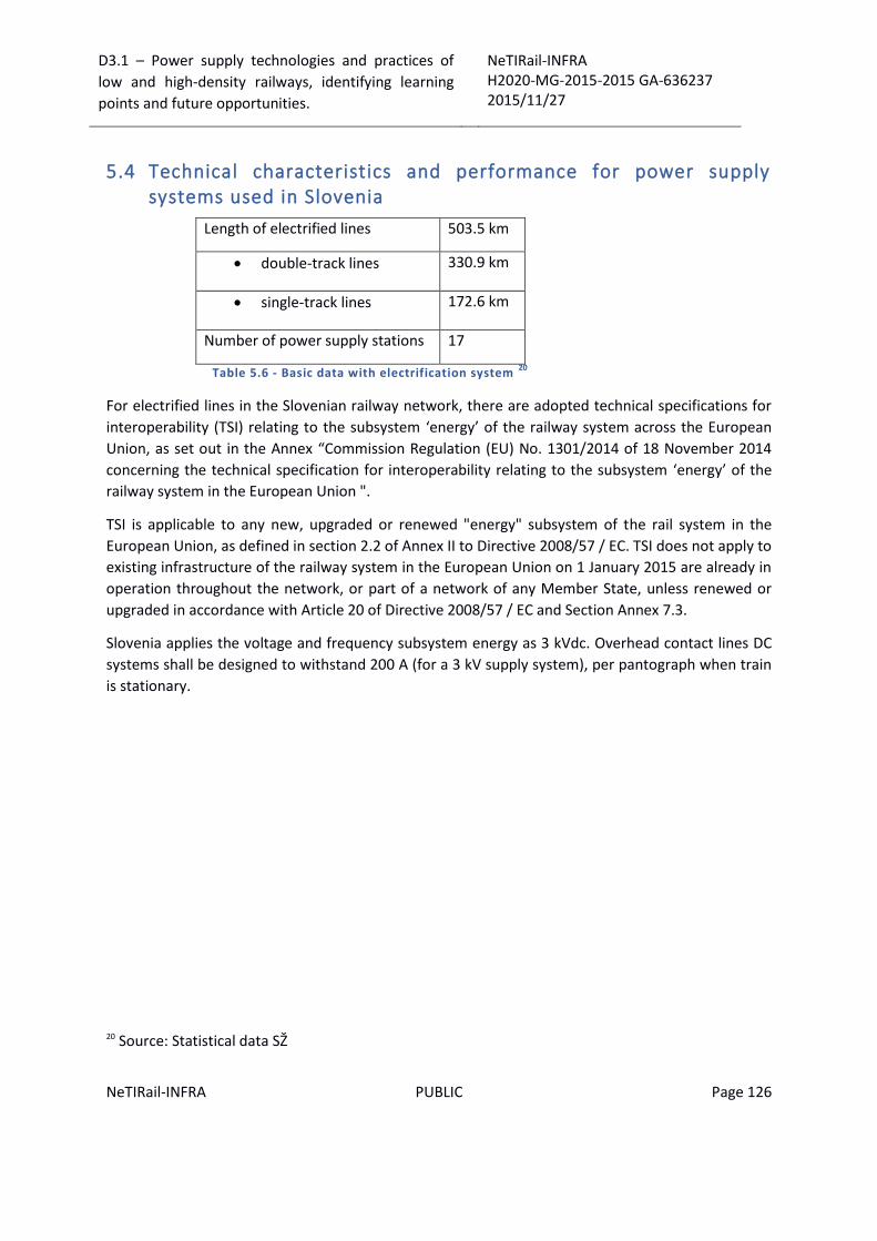
D3.1 – Power supply technologies and practices of
low and high-density railways, identifying learning
points and future opportunities.
NeTIRail-INFRA H2020-MG-2015-2015 GA-636237 2015/11/27
NeTIRail-INFRA PUBLIC Page 126
5.4 Technical characteristics and performance for power supply systems used in Slovenia
Length of electrified lines 503.5 km
double-track lines 330.9 km
single-track lines 172.6 km
Number of power supply stations 17
Table 5.6 - Basic data with electrification system 20
For electrified lines in the Slovenian railway network, there are adopted technical specifications for
interoperability (TSI) relating to the subsystem ‘energy’ of the railway system across the European
Union, as set out in the Annex “Commission Regulation (EU) No. 1301/2014 of 18 November 2014
concerning the technical specification for interoperability relating to the subsystem ‘energy’ of the
railway system in the European Union ".
TSI is applicable to any new, upgraded or renewed "energy" subsystem of the rail system in the
European Union, as defined in section 2.2 of Annex II to Directive 2008/57 / EC. TSI does not apply to
existing infrastructure of the railway system in the European Union on 1 January 2015 are already in
operation throughout the network, or part of a network of any Member State, unless renewed or
upgraded in accordance with Article 20 of Directive 2008/57 / EC and Section Annex 7.3.
Slovenia applies the voltage and frequency subsystem energy as 3 kVdc. Overhead contact lines DC
systems shall be designed to withstand 200 A (for a 3 kV supply system), per pantograph when train
is stationary.
20 Source: Statistical data SŽ

D3.1 – Power supply technologies and practices of
low and high-density railways, identifying learning
points and future opportunities.
NeTIRail-INFRA H2020-MG-2015-2015 GA-636237 2015/11/27
NeTIRail-INFRA PUBLIC Page 127
Figure 5.4 - Slovenian railway network 21
Electric power devices are stable electric traction devices enabling the undisturbed transmission of
electric power from the public distribution network to electric traction units and other energy
devices like low-voltage transformer stations, external lighting, heating of switch-points and energy
devices in buildings. The stable devices are composed of sub-stations with connection power lines
and cable conduits, and the catenary, and within the construction of the most recent sub-station a
system for the remote control of devices is being set up. Almost all electrified lines of Slovenske
železnice are electrified by a one-way system with a rated voltage of 3 kVdc, only in near-border
sections are the systems of neighbouring Austria (15 kV / 16.67 Hz) and Croatia (25 Hz / 50 Hz) built
in (see Table 5.6 and Figure 5.4).
By using power lines or cable conduits, electric power is transmitted from the medium-voltage
network to the sub-stations where it is transformed and rectified, and distributed to sections of the
catenary. With regard to demands of the line, two rectifier aggregate units with a rated current of
667 A, 1000 A or 1500 A are installed in each of the 17 sub-stations.
The catenary transmits power to the vehicles and is electrically divided into longitudinal and
transversal sections with more than 700 switches. An individual section is the catenary of one track
between stations, or of a group of tracks at a station. Due to the relatively high traction currents,
two contact wires with a cross-section of 100 mm2 and a support wire with a cross-section of 120
mm2 are mounted on the main tracks, which makes the total cross-section of the catenary of the
21 http://en.slo-zeleznice.si/en/company/infrastructure/rail_network/electric_power_system

D3.1 – Power supply technologies and practices of
low and high-density railways, identifying learning
points and future opportunities.
NeTIRail-INFRA H2020-MG-2015-2015 GA-636237 2015/11/27
NeTIRail-INFRA PUBLIC Page 128
main tracks 320 mm2. Together, all electrified tracks are over 900-km long, involving more than
24,000 poles to support the catenary.
The development of stable devices for electric traction is oriented at the modernization of existing
devices, as well as in electrification of new tracks on existing and envisaged new lines. In the area of
sub-stations, the installation of newer devices and the remote control system is envisaged to
continue, while the development of the catenary is aimed at the use of better materials and
equipment, and the reduction of impacts from the environment.

D3.1 – Power supply technologies and practices of
low and high-density railways, identifying learning
points and future opportunities.
NeTIRail-INFRA H2020-MG-2015-2015 GA-636237 2015/11/27
NeTIRail-INFRA PUBLIC Page 129
5.5 Comparative table for the five electrified case studies chosen in the NeTIRail Project
Rail Line identification
/name
Divača – Koper
Pivka - Ilirska Bistrica
Kayaş - Sincan
Divriği - Malatya
Malatya - İskenderun
Line Category Freight dominated route Low density rural /
secondary line
Busy passenger
Low density rural /
secondary line
Freight dominated route
Type of electric power supply:
Voltage levels 3 kVdc 3 kVdc 25 kVac / 50Hz 25 kVac / 50 Hz 25 kVac / 50 Hz
Current types for
electricity power supply
DC DC Alternating Current ,
Single Phase
Alternating Current ,
Single Phase
Alternating Current ,
Single Phase
Contact system type
Overhead contact lines Overhead contact lines At TCDD electrified lines
there are two system are
used, new system and
conventional system.
At Sincan-Kayaş line,
conventional type system
is used. Within new
At TCDD electrified lines
there are two system are
used, new system and
conventional system.
At Divriği - Malatya line,
conventional and new
type system is used.
At TCDD electrified lines
there are two system are
used, new system and
traditional system.
At İskenderun - Divriği
line, new type system is
used. Within new system
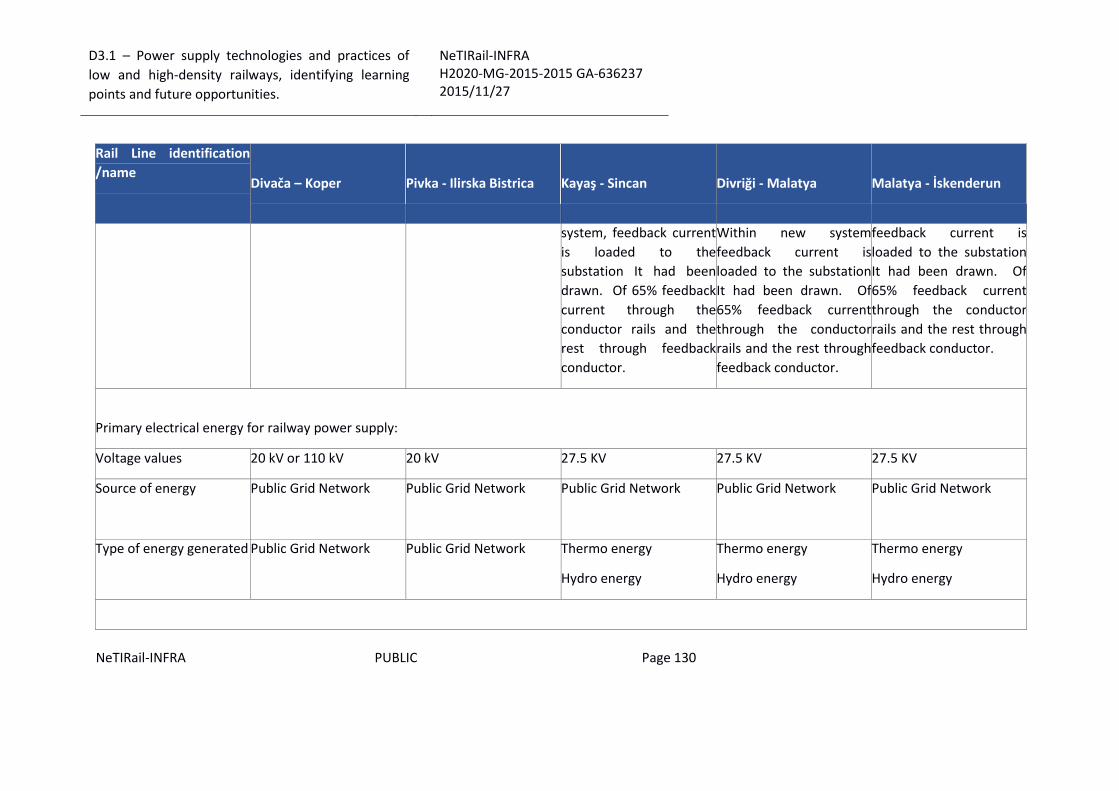
D3.1 – Power supply technologies and practices of
low and high-density railways, identifying learning
points and future opportunities.
NeTIRail-INFRA H2020-MG-2015-2015 GA-636237 2015/11/27
NeTIRail-INFRA PUBLIC Page 130
Rail Line identification
/name
Divača – Koper
Pivka - Ilirska Bistrica
Kayaş - Sincan
Divriği - Malatya
Malatya - İskenderun
system, feedback current
is loaded to the
substation It had been
drawn. Of 65% feedback
current through the
conductor rails and the
rest through feedback
conductor.
Within new system
feedback current is
loaded to the substation
It had been drawn. Of
65% feedback current
through the conductor
rails and the rest through
feedback conductor.
feedback current is
loaded to the substation
It had been drawn. Of
65% feedback current
through the conductor
rails and the rest through
feedback conductor.
Primary electrical energy for railway power supply:
Voltage values 20 kV or 110 kV 20 kV 27.5 KV 27.5 KV 27.5 KV
Source of energy
Public Grid Network Public Grid Network Public Grid Network Public Grid Network Public Grid Network
Type of energy generated
Public Grid Network Public Grid Network Thermo energy
Hydro energy
Thermo energy
Hydro energy
Thermo energy
Hydro energy

D3.1 – Power supply technologies and practices of
low and high-density railways, identifying learning
points and future opportunities.
NeTIRail-INFRA H2020-MG-2015-2015 GA-636237 2015/11/27
NeTIRail-INFRA PUBLIC Page 131
Rail Line identification
/name
Divača – Koper
Pivka - Ilirska Bistrica
Kayaş - Sincan
Divriği - Malatya
Malatya - İskenderun
Substations:
Classification by
functional types
AC/DC converter
substation
AC/DC converter station Power transformer Power transformer Power transformer
Distance between
substation
Average 10 km 22 km Depending on the field
conditions it is about
between 50km -60km
Depending on the field
conditions it is about
between 50km -60km
Depending on the field
conditions it is about
between 50km -60km
Return current circuit solution:
Type of circuit return
running rails running rails
Return Wire, running rail Return Wire, running rail Return Wire
Overhead contact lines system characteristics:

D3.1 – Power supply technologies and practices of
low and high-density railways, identifying learning
points and future opportunities.
NeTIRail-INFRA H2020-MG-2015-2015 GA-636237 2015/11/27
NeTIRail-INFRA PUBLIC Page 132
Rail Line identification
/name
Divača – Koper
Pivka - Ilirska Bistrica
Kayaş - Sincan
Divriği - Malatya
Malatya - İskenderun
Maximum speed
designed
140 km/h 100 km/h 160 km for conventional
lines
160 km for conventional
lines
160 km for conventional
lines
Static contact forces
designed
90N 90 N
Dynamic contact force
designed
140N 140 N
Adopted pre-sag
[% by span length]
0.1% 0 0.15% V>120km/h
0.2%
100<V=<120km/h
0.3% V=<100km/h
0.15% V>120km/h
0.2%
100<V=<120km/h
0.3% V=<100km/h
0.15% V>120km/h
0.2%
100<V=<120km/h
0.3% V=<100km/h
Standard height adopted 5.35 5.35 m 5.75m 5.75m 5.75m
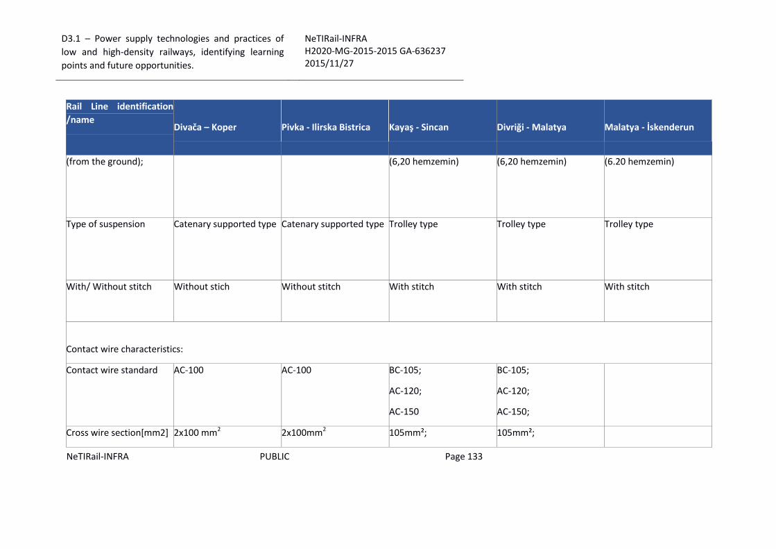
D3.1 – Power supply technologies and practices of
low and high-density railways, identifying learning
points and future opportunities.
NeTIRail-INFRA H2020-MG-2015-2015 GA-636237 2015/11/27
NeTIRail-INFRA PUBLIC Page 133
Rail Line identification
/name
Divača – Koper
Pivka - Ilirska Bistrica
Kayaş - Sincan
Divriği - Malatya
Malatya - İskenderun
(from the ground);
(6,20 hemzemin)
(6,20 hemzemin)
(6.20 hemzemin)
Type of suspension
Catenary supported type Catenary supported type Trolley type
Trolley type
Trolley type
With/ Without stitch
Without stich Without stitch With stitch With stitch With stitch
Contact wire characteristics:
Contact wire standard
AC-100 AC-100 BC-105;
AC-120;
AC-150
BC-105;
AC-120;
AC-150;
Cross wire section[mm2] 2x100 mm2 2x100mm2 105mm²; 105mm²;

D3.1 – Power supply technologies and practices of
low and high-density railways, identifying learning
points and future opportunities.
NeTIRail-INFRA H2020-MG-2015-2015 GA-636237 2015/11/27
NeTIRail-INFRA PUBLIC Page 134
Rail Line identification
/name
Divača – Koper
Pivka - Ilirska Bistrica
Kayaş - Sincan
Divriği - Malatya
Malatya - İskenderun
120 mm²;
150 mm²;
120 mm²;
150 mm²;
Material Composition
CuAg 0.1 Cu-ETP 0.1% Au Alloy (AC-120
and AC-150)
0.1% Au Alloy (AC-120
and AC-150)
Tensioning characteristics:
Tensioning type
separate separate Separate (=>120km/h);
Jointed (<120km/h);
Separate (=>120km/h);
Jointed (<120km/h);
Separate (=>120km/h);
Jointed (<120km/h);
Tensioning section length Average 1000m Average 1000m Max. 1350m;
Nominal 1250m
Max. 1350m;
Nominal 1250m
Max. 1350m;
Nominal 1250m;
Tensioning device type Pulley-wheel Pulley-wheel Pulley-wheel; Pulley-wheel; Pulley-wheel;
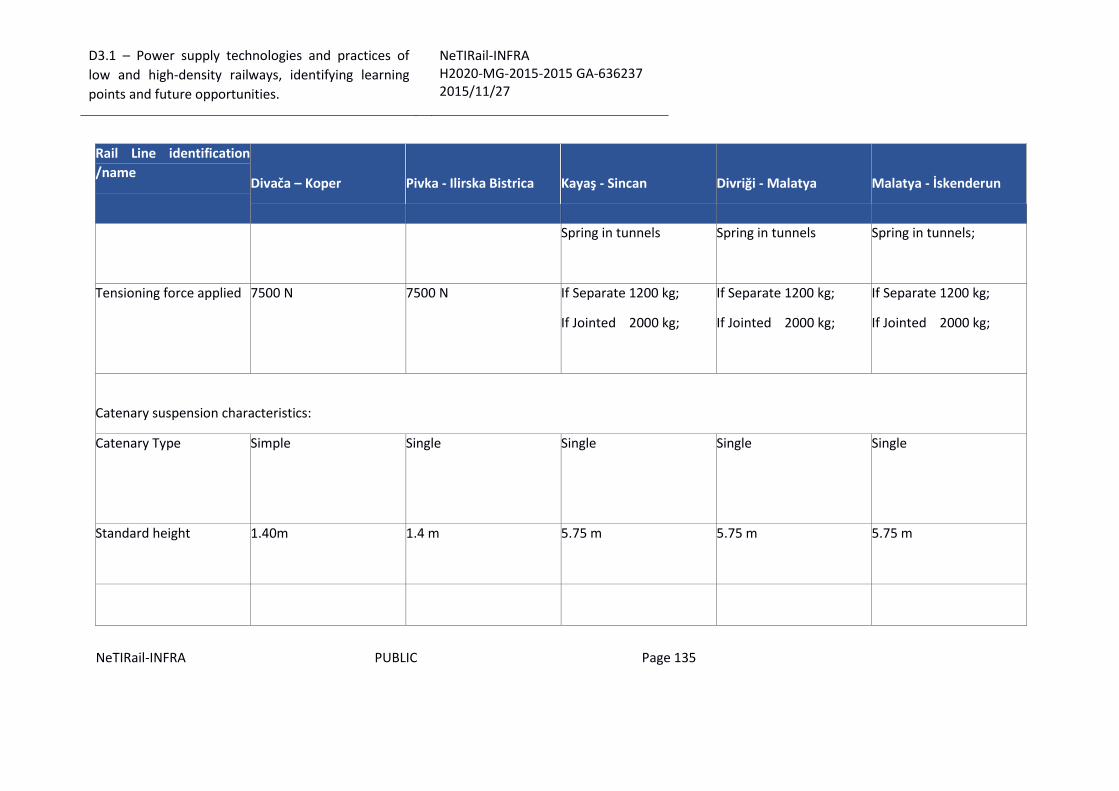
D3.1 – Power supply technologies and practices of
low and high-density railways, identifying learning
points and future opportunities.
NeTIRail-INFRA H2020-MG-2015-2015 GA-636237 2015/11/27
NeTIRail-INFRA PUBLIC Page 135
Rail Line identification
/name
Divača – Koper
Pivka - Ilirska Bistrica
Kayaş - Sincan
Divriği - Malatya
Malatya - İskenderun
Spring in tunnels Spring in tunnels Spring in tunnels;
Tensioning force applied 7500 N 7500 N If Separate 1200 kg;
If Jointed 2000 kg;
If Separate 1200 kg;
If Jointed 2000 kg;
If Separate 1200 kg;
If Jointed 2000 kg;
Catenary suspension characteristics:
Catenary Type
Simple Single
Single Single Single
Standard height
1.40m 1.4 m 5.75 m 5.75 m 5.75 m

D3.1 – Power supply technologies and practices of
low and high-density railways, identifying learning
points and future opportunities.
NeTIRail-INFRA H2020-MG-2015-2015 GA-636237 2015/11/27
NeTIRail-INFRA PUBLIC Page 136
Rail Line identification
/name
Divača – Koper
Pivka - Ilirska Bistrica
Kayaş - Sincan
Divriği - Malatya
Malatya - İskenderun
Material composition
Cu Cu - ETP
Droppers:
Droppers current type
Current caring Non-current caring Current caring Current caring Current caring
Droppers mechanical
type
Rigid Sliding Rigid Rigid Rigid
Material composition
Bz II Cu Cooper Cadmium Alloy Cooper Cadmium Alloy
Cooper Cadmium Alloy
Poles for supports of contact line:
Structural materials Steel Steel Concrete Concrete Concrete

D3.1 – Power supply technologies and practices of
low and high-density railways, identifying learning
points and future opportunities.
NeTIRail-INFRA H2020-MG-2015-2015 GA-636237 2015/11/27
NeTIRail-INFRA PUBLIC Page 137
Rail Line identification
/name
Divača – Koper
Pivka - Ilirska Bistrica
Kayaş - Sincan
Divriği - Malatya
Malatya - İskenderun
Structural design
Lattice Tube Section shape
Section shape
Section shape
Hinged cantilever:
Design type
Pull-off Pull- off There is no hinged
cantilever at TCDD
networks. So Dimensions
of the cantilever are
variable depending on
the conditions of the
field.
There is no hinged
cantilever at TCDD
networks. So Dimensions
of the cantilever are
variable depending on
the conditions of the
field.
There is no hinged
cantilever at TCDD
networks. So Dimensions
of the cantilever are
variable depending on
the conditions of the
field.
Material composition
Steel Steel Al alloy EN-10204,
EN1706, EN515, EN573-3
and EN755
Al alloy EN-10204,
EN1706, EN515, EN573-3
and EN755
Al alloy EN-10204,
EN1706, EN515, EN573-3
and EN755

D3.1 – Power supply technologies and practices of
low and high-density railways, identifying learning
points and future opportunities.
NeTIRail-INFRA H2020-MG-2015-2015 GA-636237 2015/11/27
NeTIRail-INFRA PUBLIC Page 138
Rail Line identification
/name
Divača – Koper
Pivka - Ilirska Bistrica
Kayaş - Sincan
Divriği - Malatya
Malatya - İskenderun
Neutral sections:
Design destination
- Separate Phases
Separate energy supply
Separate Phases
Separate energy supply
Separate Phases
Separate energy supply
Maximum speed
designed
- 100 km/h 160 km/h 160 km/h 160 km/h
D3.1 – Power supply technologies and practices of
low and high-density railways, identifying learning
points and future opportunities.
NeTIRail-INFRA H2020-MG-2015-2015 GA-636237 2015/11/27
NeTIRail-INFRA PUBLIC Page 139
5.6 Slovenia - case studies lines
5.6.1 Rail line Divača - Koper
Line category:
Freight dominated route
Functionalities:
The line is categorized as a Main Line related to national consideration, it is single track, electrified
line with 3 kVdc and has almost only freight traffic trains. There are only few passenger trains and
full of freight trains per day.
Length line by sections: Divača – Prešnica: 16.5 km; Prešnica – Koper: 31.5km.
It is in the category D3, the maximal permissible axle load is 22.5 tons with gauge dimension: 1435
mm and clearance gauge: UIC B 505, which is compatible with intermodal transport.
The Divača – Koper line has the characteristics of a mountain railway, with high slopes and small
radii. The starting point of the line is in Divača at 431.1 m above sea level. The line reaches sea level
at Koper Freight station. The highest altitude station of the line is the station Rodik, at 537.6 m. The
maximal gradient is 25.8 ‰ over 300 m between Hrastovlje and Rižana, while the minimal radius of
the curve is 250 m (in section Črnotiči – Hrastovlje).
Performances:
Average number of passenger trains per day is 11. Average number of freight trains per day is 79.
Capacity of the line is 82 trains per day. Maximal speed is 90 km/h.
The maximal line speed is between 65 km/h and 75 km/h for freight trains and 90 km/h for
passenger trains.
In year 2014 the following parameters were registered: 4 684 PT (passenger trains) – 0.1 MP
(millions passengers) and 20 375 FT (freight trains) – 11.04 Mt (millions of tons).
Economic aspects:
There are only short (few hours) possessions for maintenance works. The main problem is wearing
of rails, because of heavy trains and steep slopes (inclination). Maintenance is difficult also because
of no accessibility by road and of course, before mentioned heavy traffic. During summer there are
also considered fire precautions.
The Divača–Koper railway line is particularly important for international rail freight traffic, given the
role of the Port of Koper in linking the Slovenian hinterland with the European economy.
Need to upgrade from single to double tracks line. Second track will be shorter and with less
inclination.
Other characteristics:
D3.1 – Power supply technologies and practices of
low and high-density railways, identifying learning
points and future opportunities.
NeTIRail-INFRA H2020-MG-2015-2015 GA-636237 2015/11/27
NeTIRail-INFRA PUBLIC Page 140
Year of construction related to sections: Divača – Prešnica: 1876; Prešnica – Koper: 1967.
The railway line consists of two line sections. The line section Divača - Prešnica junction was
constructed in 1876 in the scope of “Istrian state railways”, when the railway line Divača – Pula was
being constructed. The line section from Prešnica junction to Koper was constructed in 1967.
Passenger traffic started in 1972 and, in 1979, a new passenger station in Koper was built.
The line was electrified in 1976. The catenary is supplied from electrical substations (ESS) at Divača,
Črnotiče and Rižana. In the course of modernization, two electrical substations were set up in Dekani
and Hrpelje - Kozina.
Need to upgrade from single to double tracks line. Second track will be shorter and with less
inclination.
Quality of the track is according to national regulations. There are several types of inspections to
control the quality of the track from personal inspections, hand measurement, and land survey
measurement, geometrical parameters measuring by train inspection, dynamic parameters
measuring train inspection.
5.6.2 Rail line Pivka - Ilirska Bistrica
Line category:
Low density rural / secondary line
Functionalities:
This particular electrified single track line with 3 kVdc, has mixed traffic, some passenger trains and
some freight trains. There are only few passenger and freight trains per day.
Length of railway line: 24.5 km
Gauge dimension and clearance gauge: 1435 mm; UIC B 505.
Contrary to it high economic importance, the axle load category of line is rather limited (category C,
i.e. 20 t/ axle loads).
Performances:
Average number of passenger trains per day is 14. Average number of freight trains per day is 6.
Capacity of the line is 63 trains per day.
Maximal speed is 75 km/h.
In year 2014 the following parameters were registered: 10 276 PT (passenger trains) – 0.4 MP
(millions passengers) and 506 FT (freight trains) – 0.08 Mt (millions of tons).
Economic aspects:
The railway line Pivka - Ilirska Bistrica - Šapjane (HŽ – Croatian Railways) is extremely important for
the port of Rijeka. It also serves an alternative route that of Rijeka-Zagreb. With the liberalization of

D3.1 – Power supply technologies and practices of
low and high-density railways, identifying learning
points and future opportunities.
NeTIRail-INFRA H2020-MG-2015-2015 GA-636237 2015/11/27
NeTIRail-INFRA PUBLIC Page 141
the rail transport market in Croatia, this railway line will also became a major force, because it
provides the shortest route from the port of Rijeka to Central Europe.
Other characteristics:
The border station for traffic exchange is Šapjane in Croatia (HŽ), which is fitted with two systems of
electrification, namely 3 kVdc (SŽ) and 25 kVac/ 50 Hz (HŽ).
Quality of the track is according to national regulations. There are several types of inspections to
control the quality of the track from personal inspections, hand measurement, land survey
measurement, geometrical parameters measuring train inspection, dynamic parameters measuring
train inspection (not on this particular line).
5.7 Turkey – case studies
5.7.1 Rail line Kayaş - Sincan
Line category:
Busy passenger
Functionalities:
This line is an electrified line with automatic block system. The length of the line is 37km
The gauge of the line is standard (clearance gauge UIC B 505, track gauge 1435mm).
Current type for power supply system is alternating current, single phase: 25kVac / 50 Hz.
Number of tracks between sections:
- Kayaş-Ankara: 3 lines
- Ankara-Marşandiz: 4 lines
- Marşandiz-Sincan: 3 lines
The maximum gradient on the line is 17.8 ‰. A block system with 3-aspect signals is used; block
section length is the same for all lines, namely 700 meters.
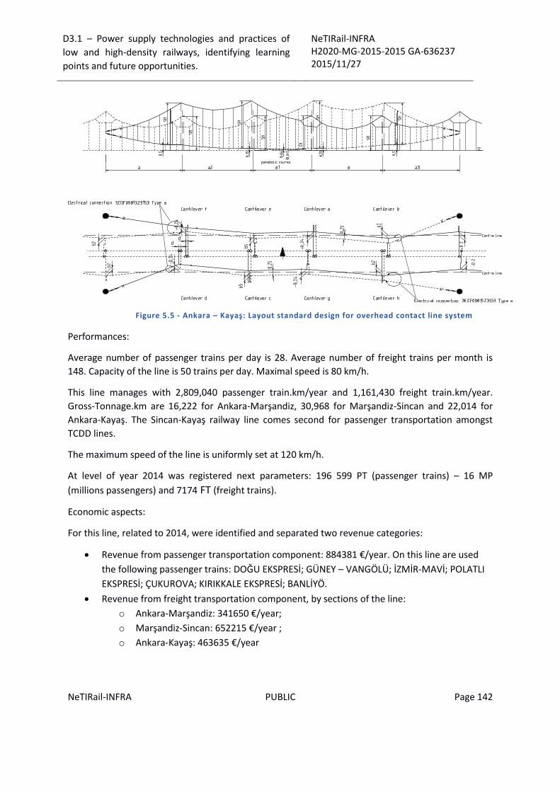
D3.1 – Power supply technologies and practices of
low and high-density railways, identifying learning
points and future opportunities.
NeTIRail-INFRA H2020-MG-2015-2015 GA-636237 2015/11/27
NeTIRail-INFRA PUBLIC Page 142
Figure 5.5 - Ankara – Kayaş: Layout standard design for overhead contact line system
Performances:
Average number of passenger trains per day is 28. Average number of freight trains per month is
148. Capacity of the line is 50 trains per day. Maximal speed is 80 km/h.
This line manages with 2,809,040 passenger train.km/year and 1,161,430 freight train.km/year.
Gross-Tonnage.km are 16,222 for Ankara-Marşandiz, 30,968 for Marşandiz-Sincan and 22,014 for
Ankara-Kayaş. The Sincan-Kayaş railway line comes second for passenger transportation amongst
TCDD lines.
The maximum speed of the line is uniformly set at 120 km/h.
At level of year 2014 was registered next parameters: 196 599 PT (passenger trains) – 16 MP
(millions passengers) and 7174 FT (freight trains).
Economic aspects:
For this line, related to 2014, were identified and separated two revenue categories:
Revenue from passenger transportation component: 884381 €/year. On this line are used
the following passenger trains: DOĞU EKSPRESİ; GÜNEY – VANGÖLÜ; İZMİR-MAVİ; POLATLI
EKSPRESİ; ÇUKUROVA; KIRIKKALE EKSPRESİ; BANLİYÖ.
Revenue from freight transportation component, by sections of the line:
o Ankara-Marşandiz: 341650 €/year;
o Marşandiz-Sincan: 652215 €/year ;
o Ankara-Kayaş: 463635 €/year
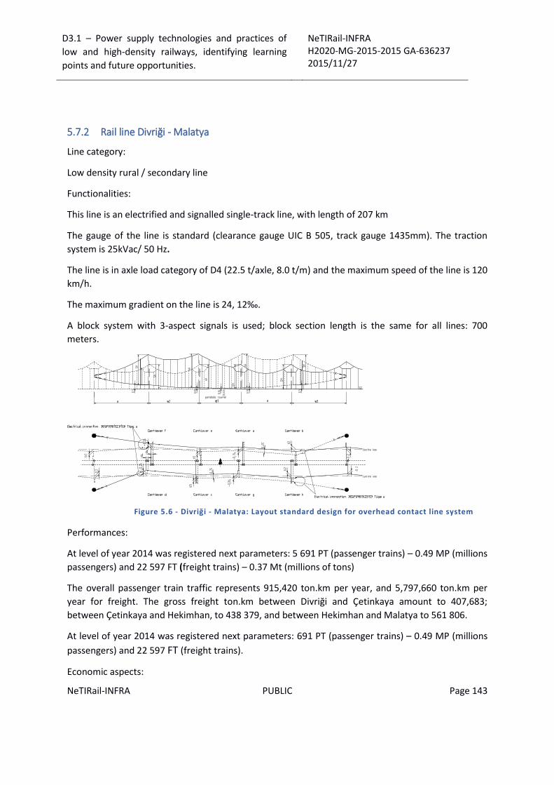
D3.1 – Power supply technologies and practices of
low and high-density railways, identifying learning
points and future opportunities.
NeTIRail-INFRA H2020-MG-2015-2015 GA-636237 2015/11/27
NeTIRail-INFRA PUBLIC Page 143
5.7.2 Rail line Divriği - Malatya
Line category:
Low density rural / secondary line
Functionalities:
This line is an electrified and signalled single-track line, with length of 207 km
The gauge of the line is standard (clearance gauge UIC B 505, track gauge 1435mm). The traction
system is 25kVac/ 50 Hz.
The line is in axle load category of D4 (22.5 t/axle, 8.0 t/m) and the maximum speed of the line is 120
km/h.
The maximum gradient on the line is 24, 12‰.
A block system with 3-aspect signals is used; block section length is the same for all lines: 700
meters.
Figure 5.6 - Divriği - Malatya: Layout standard design for overhead contact line system
Performances:
At level of year 2014 was registered next parameters: 5 691 PT (passenger trains) – 0.49 MP (millions
passengers) and 22 597 FT (freight trains) – 0.37 Mt (millions of tons)
The overall passenger train traffic represents 915,420 ton.km per year, and 5,797,660 ton.km per
year for freight. The gross freight ton.km between Divriği and Çetinkaya amount to 407,683;
between Çetinkaya and Hekimhan, to 438 379, and between Hekimhan and Malatya to 561 806.
At level of year 2014 was registered next parameters: 691 PT (passenger trains) – 0.49 MP (millions
passengers) and 22 597 FT (freight trains).
Economic aspects:

D3.1 – Power supply technologies and practices of
low and high-density railways, identifying learning
points and future opportunities.
NeTIRail-INFRA H2020-MG-2015-2015 GA-636237 2015/11/27
NeTIRail-INFRA PUBLIC Page 144
For this line, related to 2014, were identified and separated two revenue categories:
Revenue from passenger transportation component: 359064 €/year. On this line are used
the following passenger trains: DOĞU EKSPRESİ; GÜNEY-VANGÖLÜ; 4EYLÜL.
Revenue from freight transportation component, by sections of the line:
o Divriği-Çetinkaya: 8586191 €/year;
o Çetinkaya-Hekimhan: 9232678 €/year
o Hekimhan-Malatya: 11832168 €/year
The main expenses for this line is considered to be the maintenance operations and the rent.
Divriği-Malatya line section is low-density line. Regarding that it is not possible to increase the traffic
density it will be possible to decrease the maintenance cost and the line section will be more
economic.
Other characteristics:
The main problematic of the line section is winter condition is very hard. It snows more than other
sections and due to snowing and icing, some problems on track and S&C occurs.
5.7.3 Rail line Malatya - İskenderun
Line category:
Freight dominated route
Functionalities:
This line is an electrified and signalled single-track line, with length of 374 km.
The gauge of the line is standard (clearance gauge UIC B 505, track gauge 1435mm). The traction
system is 25kVac/ 50 Hz.
The line is in axle load category of D4 (22.5 t/axle, 8.0 t/m) and the maximum speed of the line is 120
km/h. The maximum gradient on the line is 21‰.
A block system with 3-aspect signals is used; block section length is the same for all lines: 700
meters.
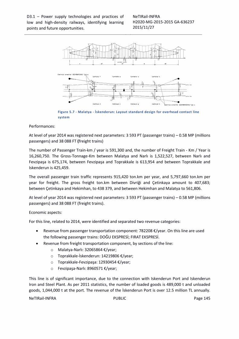
D3.1 – Power supply technologies and practices of
low and high-density railways, identifying learning
points and future opportunities.
NeTIRail-INFRA H2020-MG-2015-2015 GA-636237 2015/11/27
NeTIRail-INFRA PUBLIC Page 145
Figure 5.7 - Malatya - İskenderun: Layout standard design for overhead contact line
system
Performances:
At level of year 2014 was registered next parameters: 3 593 PT (passenger trains) – 0.58 MP (millions
passengers) and 38 088 FT (freight trains)
The number of Passenger Train-km / year is 591,300 and, the number of Freight Train - Km / Year is
16,260,750. The Gross-Tonnage-Km between Malatya and Narlı is 1,522,527, between Narlı and
Fevzipaşa is 675,174, between Fevzipaşa and Toprakkale is 613,954 and between Toprakkale and
Iskenderun is 425,459.
The overall passenger train traffic represents 915,420 ton.km per year, and 5,797,660 ton.km per
year for freight. The gross freight ton.km between Divriği and Çetinkaya amount to 407,683;
between Çetinkaya and Hekimhan, to 438 379, and between Hekimhan and Malatya to 561,806.
At level of year 2014 was registered next parameters: 3 593 PT (passenger trains) – 0.58 MP (millions
passengers) and 38 088 FT (freight trains).
Economic aspects:
For this line, related to 2014, were identified and separated two revenue categories:
Revenue from passenger transportation component: 782208 €/year. On this line are used
the following passenger trains: DOĞU EKSPRESİ; FIRAT EKSPRESİ.
Revenue from freight transportation component, by sections of the line:
o Malatya-Narlı: 32065864 €/year;
o Toprakkale-İskenderun: 14219806 €/year;
o Toprakkale-Fevzipaşa: 12930454 €/year;
o Fevzipaşa-Narlı: 8960571 €/year;
This line is of significant importance, due to the connection with Iskenderun Port and Iskenderun
Iron and Steel Plant. As per 2011 statistics, the number of loaded goods is 489,000 t and unloaded
goods, 1,044,000 t at the port. The revenue of the İskenderun Port is over 12.5 million TL annually.
D3.1 – Power supply technologies and practices of
low and high-density railways, identifying learning
points and future opportunities.
NeTIRail-INFRA H2020-MG-2015-2015 GA-636237 2015/11/27
NeTIRail-INFRA PUBLIC Page 146
Line capacity enhancement is expected to increase the revenue of the port by increasing the
capacity of usage of the hinterland, by means of decreasing the downtime related to maintenance.
The connection to the iron and steel plant is also of significant importance for freight transportation.
In particular, iron ore is mined from Divriği and transported to İskenderun by rail.
The main expenses for this line is considered to be the maintenance operation.

D3.1 – Power supply technologies and practices of
low and high-density railways, identifying learning
points and future opportunities.
NeTIRail-INFRA H2020-MG-2015-2015 GA-636237 2015/11/27
NeTIRail-INFRA PUBLIC Page 147
6 Design of data repository support for analyses for existing power supply installations
6.1 Design of conceptual model of data repository
The entity relationship diagram (ERD) designed to database support for analysis of existing
installations (power supply for high and low density lines) is presented below.
Figure 6.1 Structure of database support for analysis of existing installations: power
supply for high and low density lines

D3.1 – Power supply technologies and practices of
low and high-density railways, identifying learning
points and future opportunities.
NeTIRail-INFRA H2020-MG-2015-2015 GA-636237 2015/11/27
NeTIRail-INFRA PUBLIC Page 148
The structure of the database consists of principal entities (entities on which will make analysis) and
secondary entities that support the characterization of principal entities (lists of attributes for the
principal entities).
The database "Support for analysis of existing installations" was conceived as an add-on for database
created in Task 2.1, in order to collect additional data relating to the power supply system for
electrified railway lines.
6.2 Summary of database
In this section, presents the list of the entities constituting the database support for analysis of
existing installations: power supply for high and low density lines.
Name Description
countries In this table is managed information on the countries for which you wish to perform analysis
type_lines In this table is managed information on the railway types for which you wish to perform analysis
type_poles In this table is managed information regarding the classification and characteristic of different types of poles
source_primary_energy In this table is managed information regarding the source of primary energy
type_power_supply_systems In this table is managed information regarding the classification and characteristic of different types of power supply systems
type_generate_energy In this table is managed information regarding the classification and characteristic of different types of generate energy
type_droppers In this table is managed information regarding the classification and characteristic of different types of droppers
suspension_types In this table is managed information regarding the classification and characteristic of different types of suspension
type_contact_line In this table is managed information regarding the contact line type systems
type_wire_grade In this table is managed information regarding the classification different types of wire grade
type_tensioning In this table is managed information regarding the classification different types of tensioning device
railways In this table is managed information regarding the railways network at country level
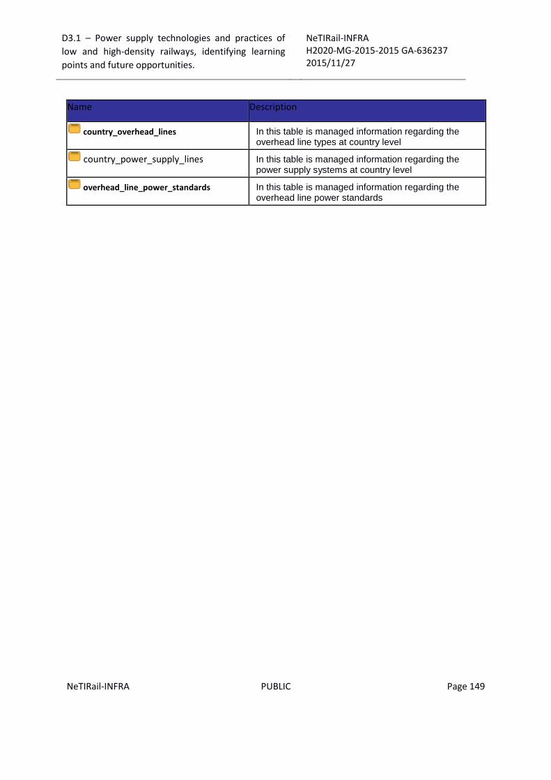
D3.1 – Power supply technologies and practices of
low and high-density railways, identifying learning
points and future opportunities.
NeTIRail-INFRA H2020-MG-2015-2015 GA-636237 2015/11/27
NeTIRail-INFRA PUBLIC Page 149
Name Description
country_overhead_lines In this table is managed information regarding the overhead line types at country level
country_power_supply_lines In this table is managed information regarding the power supply systems at country level
overhead_line_power_standards In this table is managed information regarding the overhead line power standards
D3.1 – Power supply technologies and practices of
low and high-density railways, identifying learning
points and future opportunities.
NeTIRail-INFRA H2020-MG-2015-2015 GA-636237 2015/11/27
NeTIRail-INFRA PUBLIC Page 150
7 Conclusions
Electrification systems are classified by three main parameters: voltage level of electricity power
supply; current types used for electricity power supply; contact system type with electricity power
supply.
The most common DC voltage power supply systems are 600 Vdc and 750 Vdc - for trams and
metros. Other important categories, for intercity lines are: 1.5 kVdc and 3 kVdc.
The lower voltages are often used with third or fourth rail systems, whereas voltages levels above
1kV should be raised up to overhead lines, for safety reasons.
Alternative current (AC) - This category represents with no exception, the overhead power supply
system. This allows much higher voltages and therefore smaller currents along the line, which means
smaller energy losses for long railways, lesser components renewal.
Taking in consideration the variety of railway electrification systems, which can vary even within a
country, trains often have to pass from one system to another. In Europe, it is common to use four
system locomotives (1.5 kVdc; 3 kVdc; 15 kVac / 16.7 Hz; 25 kVac / 50 Hz).
Reliability in operation electrified railway networks depends by the availability and reliability of the
electricity traction supply system. Contact line requirements – overhead line or third rail – have to
take in consideration the contact line cannot be installed redundant, from economic and technical
reasons.
Main disadvantages of electric power supply system are the high cost as initial investment and
continuous addition maintenance; these could be uneconomic on low traffic routes. Bringing
electric power supply as an upgrade for a railway line has opposite effect as the one desired: the
maintenance costs will grow. The cost reduction is not an objective, even if all infrastructure
managers and rolling stock operators claim lower maintenance costs as principal condition for new
investments and upgrades.
Main benefits of electrification are increased productivity of railway infrastructure as well as rolling
stock: locomotives and wagons.
Overhead lines represent a transporting system used to transmit electrical energy to trains from the
energy supply point.
The contact line, as wire, is grooved to allow a clamp to attach the dropper wire and to be fixed on
the top side. The tension of the wire is maintained by weights suspended (most usual solution) at
each end of its length.
Interoperability is the most important requirement for existing and newest railway power supply
systems, not only for present period but more important for the futures; this became a political goal
of the European Community (EC).

D3.1 – Power supply technologies and practices of
low and high-density railways, identifying learning
points and future opportunities.
NeTIRail-INFRA H2020-MG-2015-2015 GA-636237 2015/11/27
NeTIRail-INFRA PUBLIC Page 151
Overhead contact line systems include: catenary wire, contact wire, return current conductors,
earthed conductors, lightning protection conductors, feeder and parallel feeder lines, foundations,
supporting structures and other components which serve to hold and support contact wire and
conductors, switchgear equipment, monitoring and protective equipment.
To achieve good high-speed current collection, it is necessary to keep the contact wire geometry
within defined limits; this is responsibility by a second wire known as the messenger wire (US &
Canada) or catenary (Europe). This catenary wire is attached to the contact wire at regular intervals
by vertical wires known as droppers.
The contact wire is zigzagged slightly to the left and right of centre at each successive support poles,
so that the pantograph wears evenly.
Compound overhead contact line system uses a second support wire – auxiliary wire - between the
catenary wire and the contact wire, and represents an improvement of the system.
The pantograph is the most important external component which influences the performance and
the life cycle of the contact line system. For this reason, its characteristics and performance are
described in this report.
The contact lines should be at constant mechanical tension to prevent pantograph oscillations in the
electrical lines and to avoid producing waves of contact lines; tensioning the line makes these
functions.
An electric multiple unit or EMU is a multiple unit train consisting of self-propelled carriages, using
electricity as the motive power; most EMUs are used for passenger trains.
Neutral sections usually consist of an earthed section of wire which is separated from the contact
lines on either side by insulating material; the pantograph will not collect power traction from one
section to the other. Main roles are: section insulator; phase separation.
Systems from "third rail" category are implementing railways lines that are supplying electricity
through a rigid conductor placed continuously near or between the railroad tracks; it is mostly used
in systems for transport passengers, where the system has its own alignment. The main
disadvantage of third rail systems is that they present the hazard of electric shock because higher
system voltages; for this reason all voltages used, above 1500 V are not considered safe and present
higher resistive losses compared to higher voltage overhead line systems.
The world speed record for a third rail train is 174 km/h reached on 11 April 1988 by a British Class
442 EMU.
There are systems that use a combination of power supply systems using third rail for part of the
system, and overhead catenary system or diesel power engine for the rest of the track section.
However, the best technical solution is to achieve full compatibility of entire networks. This is the
cause of conversions from third rail to overhead contact line supply (or vice versa).
D3.1 – Power supply technologies and practices of
low and high-density railways, identifying learning
points and future opportunities.
NeTIRail-INFRA H2020-MG-2015-2015 GA-636237 2015/11/27
NeTIRail-INFRA PUBLIC Page 152
The most representative and high performance existing overhead contact lines (OCL) systems are
presented as technical characteristics and related to their category of voltage and frequency used.
These categories are: OCL for 3kVdc; OCL for 1.5 kVdc; OCL for 15kVac/ 16.7Hz; OCL for 25 kVac/
50Hz.
The operating requirements and the power supply systems of long-distance main line traffic are the
factors leading to the use of overhead contact lines as traction energy supply installations for
railways with low and medium traffic density, capable to provide high energy with high voltage to
traction vehicles. Lines with low density traffic give opportunity to improve the infrastructure for
becoming high speed lines.
Traffic lines for high density and short distance are mostly considered suitable for local area traffic,
commuters’ traffic, etc., where the railway traffic solution can decrease traffic congestions in high
populated areas.
Designing new railway power supply systems have to consider climatic requirements: outdoor
temperature; wind velocities and wind loads; corrosive substances from environment; lightning
voltage surges; snow and icing of contact lines and infrastructure.
For designing new overhead power supply systems, as modern practice, compound catenary
systems feature less pantograph vertical motion and less vibrations but larger current capacity and
require a larger number of components, resulting in a more complex design.
Simple catenary system is used especially in Europe and pre sag has role to compensate large
vertical motion of the pantograph. This design can be effective for the overhead lines on the French
and German high-speed lines which have large span amplitude, but is less effective for overhead
lines with small amplitudes like the Italian high-speed line, also for Shinkansen line. When designing
new power supply systems, concerns should be considered selecting components and technologies
will be used: selection of the overhead contact line design; selection of conductor cross sections and
tensile forces; selection of span lengths; selection of system height; design of contact lines in
tunnels; adoption of contact wire pre-sag; selection of dropper spacing; using of a stitch wire;
selection of tensioning section length.
Maintenance process is direct dependent by inspection activities. Parameters to inspect for
overhead contact line: wear grade of contact line; longitudinal deviation of contact line; transversal
height deviation of contact line; other characteristics inspected.
At present special vehicles are used for regular inspections; these vehicles contain special equipment
that makes the evaluation of the functionality and wear of the railways.
A theory gaining credibility is to fit the inspection systems to the trains used for commercial service,
so that measurements can be performed during normal operation.
In the last part technical characteristics and performance for systems used in United Kingdom,
Netherlands, Turkey, and Slovenia are presented.
D3.1 – Power supply technologies and practices of
low and high-density railways, identifying learning
points and future opportunities.
NeTIRail-INFRA H2020-MG-2015-2015 GA-636237 2015/11/27
NeTIRail-INFRA PUBLIC Page 153
Seven railway lines were chosen to complete a list with case studies for next tasks of the project.
Five from these are electrified lines and a comparative table with detailed technical characteristics,
related to their power supply systems, are provided. Also, are presented description related to
functionalities, performance, economic aspects, etc.
These lines are for Slovenia: Divača - Koper (as freight dominated route) and Pivka - Ilirska Bistrica
(as low density rural / secondary line). For Turkey, the INTADER were selected railway lines: Kayaş -
Sincan (as busy passenger), Divriği - Malatya (as low density rural / secondary line) and Malatya -
İskenderun (as freight dominated route).
Main objectives when railways are modernized: allowing heavier trains to run safely and
economically at faster speeds; improving productivity; providing better customer service to rail
users.
Framing a railway line in one of the three categories, defined in project analysis, it is subjective; a
line of high-density transport for one region could be a low-density transportation line for other
infrastructure manager, in another geographic region. In this way, wear of rail infrastructure and
maintenance activities costs are more pronounced, in the same period of time, for one situation
than for the other, although both cases are qualified as high density transport.
Current strategies for railways modernization are focused on:
Track and power supply infrastructure modernization for high speed lines.
Railway modernization adopting strategies focused for designing of dedicated freight routes
which means for carrying freight traffic at higher speeds and increased axle loads.
In case of the railway power supply systems, the most important improvement is the upgrading from
systems based on DC voltage to high-voltage systems with alternating current; and as a default will
also change the type of contact from third rail to overhead contact line. This modernization will bring
significant extra traction power for locomotives, which implies a higher travel speed and larger
capacity of transportation. Also, the loss of electric power will be lower in AC power supply systems
than in DC variant. Other improvements are related to selecting the best options, as presented in
deliverable, for each component or subsystem that make up power supply systems: overhead
quality wire, tensioning line devices, neutral sections provided, type of catenary, type of droppers,
using of a stitch wire, inspection and maintenance quality, etc.
For the situation of busy passenger line, infrastructure modernization is necessary to serve in good
conditions the social demands. Meanwhile, expenses incurred by infrastructure improvements are
economic feasible as this investment will be recovered from covering increased demand of
passenger traffic; so, this situation a good return on investment should be realised. The main target
of modernization is to increase the speed of trains in this category of line. However, with the
upgrade from third rail to overhead line the investment cost also need to include potential
modifications to structures and tunnels to allow electrical clearances between the structures and the
high voltage overhead line. In many cases the changes to existing structures can be a very expensive
part of any new electrification scheme or the upgrade from third rail systems to AC overhead line
systems.

D3.1 – Power supply technologies and practices of
low and high-density railways, identifying learning
points and future opportunities.
NeTIRail-INFRA H2020-MG-2015-2015 GA-636237 2015/11/27
NeTIRail-INFRA PUBLIC Page 154
Freight category dominated route also has the advantage that the investments to be recovered on
the basis of covering the transport needs. Most important improvement for better utilisation of
freight category dominated route is to increase the axle loads on the routes, with immediate result
to increase railway capacity. The objectives could be summarised as to have axle loads of 30 tonnes
for new lines because that could be designed according to highest technical requirements, and for
the current lines to increase loading capacity up to 25 tonnes per axle, obvious with improvements
even for tracks and wagons.
Low density rural/ secondary line represents a different situation. Increasing traffic density is mainly
dependent on external factors. Modernisation of line involves costs that may not be recovered. In
this way, increasing efficiency could be possible through decreasing the maintenance cost; with this
strategy, the line section will become more economic. Any improvement proposed at the others
categories will contribute to decreasing maintenance expenses but any investment would only be
realised if an economic assessment proved the scheme worthwhile. For low density rural/secondary
lines other technologies may provide effective returns, for example if on train energy storage could
be used in combination with electrification so that less infrastructure investment is required and the
on board energy storage is used for carrying the train along lesser used sections and can be used to
avoid expensive alterations to structures.

D3.1 – Power supply technologies and practices of
low and high-density railways, identifying learning
points and future opportunities.
NeTIRail-INFRA H2020-MG-2015-2015 GA-636237 2015/11/27
NeTIRail-INFRA PUBLIC Page 155
8 References
1. Overhead Contact Line Systems for Main-line Railways. AG, Siemens. s.l. : www.siemens.com,
2012.
2. Bartels, S, Herbert, W. and Seifert, R. High-speed pantograph for the ICE .
3. Braun, E. Connection of railway substations to the nationa three-phase power supply for the
Madrid-Seville high-speed line. Elektrische Bahnen. 5/1990, 1990.
4. —. Power supply of the high-speed line Madrid - Seville. Elektrische Bahnen. 12/1990, 1990.
5. Frey, Sheilah. Railway Electrification Systems & Engineering. 2012.
6. Harprecht, W. Modern installations for traction power supply. Die Bundesbahn. 7/1986, 1986.
7. Kiessling, Puschmann, Schmieder, Schneider. Contact Lines for Electric Railways - Planning,
Design, Implementation, Maintenance; Second Edition. 2012.
8. Herbert, W. Development and operating experience with the DSA 350S high speed pantograph for
the ICE.
9. Horstman, D. Budzinski, F. Pirwitz, J. The dual system traction equipment of the high speed train
Velaro for Russia. ETG-Fachberichte. 107 /108 (2007), 2007.
10. Hardmeier, W., Schneider, A. Direttissima Italy, high-speed lines Bologna-Florence and Florence-
Rome. 1989.
11. Wittke, V. and Bauer, G. Standardised traction power substations without central compressed
air supply at German Railway. Elektrische Bahnen. 8/1985, 1985.
12. Grimrath, H. and Reuen, H. Electrification of line Elmshorn-ltzehoe with overhead contact line
system Sicat S1.0. Elektrische Bahnen. 10/1998, 1998.
13. Ungvari, S. and Paul, G. Overhead contact line Sicat Hl.O for the new high-speed line Cologne-
Rhine/Main. Elektrische Bahnen. 7/1998, 1998.
14. Kohlhaa.s, J., et al. Interoperable overhead contact line Sicat H1.0 for high-speed line Cologne-
Rhine/Main . Elektrische Bahnen . 7/2002 , 2002 .
15. Thoresen, Th. E. and Gjertsen, E. New overhead contact lines for Norges Statsbaner. Elektrische
Bahnen. 4/1996, 1996.
16. Hahn, G. Overhead contact line design of the Loetschberg base tunnel. Elektrische Bahnen.
5/2007, 2007.
17. Lortscbei, M., Aeberhard, Z. and Scbiu, R. Demand on traction power for the Loetschberg lines.
Elektrische Bahnen. 11/2007 , 2007 .

D3.1 – Power supply technologies and practices of
low and high-density railways, identifying learning
points and future opportunities.
NeTIRail-INFRA H2020-MG-2015-2015 GA-636237 2015/11/27
NeTIRail-INFRA PUBLIC Page 156
18. Kocher, M. The new overhead contact line system "BN 160" of Bern-Neuenburg Railway.
Information brochure of BLS.
19. Vega, T. High-speed line Madrid-Sevilla completely operated with AC 25 kV 50Hz. Elektrische
Bahnen. 3/2003, 2003.
20. Roldan, S. and Vega, T. New high-speed line Madrid-Toledo. In Elektrische Bahnen. 2/2006,
2006.
21. Chambron, E. Construction of the TGV atlantique project and the civil engineering works. In:
Revue Generale des Chemins de Fer. Revue Generale des Chemins de Fer. 12/1986, 1986.
22. Luppi, J. and Lamon, J.-P. History of 25kV contact lines . Revue Generale des Chemins de Fer .
3/1992 , 1992 .
23. Watanabe, K. Review and perspektive of Shinkansen. Elektrische Bahnen. 5/1985, 1985.
24. Junsheng, L. and Zimmert, G. Electrification of the line Harbin - Dalian within the Peoples
Republic of China. Elektrische Bahnen. 3/2001 , 2001 .
25. Altmann, A., Matthes, R. and Rister, S. Electrification of the high-speed line HSL Zuid. Elektrische
Bahnen. 5/2005, 2005.
26. Liu Heyun, Gu Xiaosong, Tang Wenbin. Icing and Anti-Icing of Railway Contact Wires. 2012.
27. Yasu Oura, Yoshifumi Mochinaga, Hiroki Nagasawa. Railway Electric Power Feeding Systems
(Japan Railway & Transport Review). Japan Railway & Transport Review. 16/1998.
28. Estimation of electrical losses in Network Rail Electrification Systems V1.0, 20.01.10.
29. P. Ramaekers, T. de Wit, M. Pouwels,. "Hoe druk het is nu werkelijk op het Nederlandse spoor?”
Centraal Bureau voor de Statistiek . s.l. : Den Haag/Heerlen. , February 2009.
30. DESIGN GUIDELINES. Guide to Station Planning and Design Issue 1; Network Rail. 2011.
31. SKIBICKI, Jacek. The new version of contact-less method for localisation of catenary contact wire
– theoretical assumption. PRZEGLĄD ELEKTROTECHNICZNY. 7/2013, 2013.
32. K. Lee, Y.H. Cho, Y. Park, S. Kwon. Improvements of Existing Overhead Lines for 180 km/h
operation of the Tilting Train.

D3.1 – Power supply technologies and practices of
low and high-density railways, identifying learning
points and future opportunities.
NeTIRail-INFRA H2020-MG-2015-2015 GA-636237 2015/11/27
NeTIRail-INFRA PUBLIC Page 157
4 ANNEX 1: Power supply systems related to power supply voltage and type of current
4.1 Electrification system 600 Vdc
This voltage is mostly used by older tram systems worldwide but by a few new ones as well.
Country Name of system Location
Australia Adelaide Metro tramway Adelaide
Yarra Trams Melbourne
Belgium Belgian Coast Tram Antwerp
Brussels trams De Panne to Knokke
Ghent Tram Brussels
Calgary Transit C-Train Ghent
Canada Edmonton Transit LRT Calgary
Toronto Transit Commission Edmonton
most tram lines Toronto
Czech
Republic Blackpoll Tramway
England Tallinn tram Blackpoll
Estonia Helsinki tram Tallinn
Finland Augsburg tram Helsinki
Germany BKV Augsburg
Hungary DKV Budapest
MVK Zrt. Debrecen
Public transport in Szeged Miskolc
BKV Szeged
Most tram lines Budapest
Italy Most tram lines

D3.1 – Power supply technologies and practices of
low and high-density railways, identifying learning
points and future opportunities.
NeTIRail-INFRA H2020-MG-2015-2015 GA-636237 2015/11/27
NeTIRail-INFRA PUBLIC Page 158
Country Name of system Location
Japan Chōshi Electric Railway
Eizan Electric Railway Chōshi, Chiba
Enoshima Electric Railway Kyoto, Kyoto
Iyotetsu Takahama Line Kanagawa
Shizuoka Railway Matsuyama, Ehime
Tokyu Setagaya Line Shizuoka, Shizuoka
Amsterdam Tram Tokyo
Netherlands Rotterdam tram Amsterdam
Trams in The Hague Rotterdam
city tram networks The Hague
Suburban trams in Łódź, Konstantynów
Łódzki, Lutomiersk, Ozorków, Pabianice and
Zgierz
Warszawa and suburbs
city tram networks Łódź
Arad tramway system Bydgoszcz, Częstochowa, Elbląg,
Gdańsk, GOP, Gorzów Wielkopolski,
Grudziądz, Kraków , Poznań, Szczecin,
Toruń, Warszawa (Warsaw), Wrocław
Romania Botoşani tramway system Arad
Craiova tramway system Botoşani
Iaşi tramway system Craiova
Oradea tramway system Iaşi
Sibiu-Răşinari Narrow Gauge Railway Oradea
Timişoara tramway system Sibiu county
Belgrade tram system Timişoara
Serbia Trenčianska elektrická železnica (TREŽ) Belgrade
Slovakia Basel Trams (BVB) Trenčianska Teplá – Trenčianske
Teplice

D3.1 – Power supply technologies and practices of
low and high-density railways, identifying learning
points and future opportunities.
NeTIRail-INFRA H2020-MG-2015-2015 GA-636237 2015/11/27
NeTIRail-INFRA PUBLIC Page 159
Country Name of system Location
Switzerland Bern Trams (Bernmobil) Basel
Dolderbahn Bern
Geneva Trams (TPG) Zürich
Regionalverkehr Bern-Solothurn (RBS) Geneva
Zürich Trams (VBZ) Canton Bern
Kenosha Streetcar Zürich
United States MBTA Kenosha, Wisconsin
RTA Rapid Transit Boston
San Diego Electric Railway & San Diego
Trolley
Cleveland, Ohio
San Francisco Muni San Diego
SEPTA San Francisco
4.2 Electrification system 750 Vdc
This voltage is used for most modern tram systems.
Country Name of system Location
Argentina PreMetro line E2 Buenos Aires
Tranvía del Este Buenos Aires
Australia GoldLinQ Gold Coast, Queensland
Light rail in Sydney Sydney
Austria Local lines of Stern & Hafferl
Austria/
Switzerland
Internationale Rheinregulierungsbahn River Rhine / Lake Constance
Brazil MetrôRio Rio de Janeiro
Germany Albtalbahn Rhein-Haardtbahn
Cologne-Bonn Tram Cologne to Bonn and its suburbs.
Greece Athens Tram Athens

D3.1 – Power supply technologies and practices of
low and high-density railways, identifying learning
points and future opportunities.
NeTIRail-INFRA H2020-MG-2015-2015 GA-636237 2015/11/27
NeTIRail-INFRA PUBLIC Page 160
Country Name of system Location
Hong Kong Light Rail (MTR) Hong Kong
India Kolkata Metro Line 1 Kolkata
Namma Metro Bangalore
Ireland LUAS Dublin
Italy Metropolitana di Genova Genova
Japan Enshū Railway Hamamatsu, Shizuoka
Hakone Tozan Railway Line Hakone, Kanagawa
Iyotetsu Yokogawara Line and Gunchū Line Ehime
Yokkaichi Asunarou Railway Utsube Line,
Hachiōji Line
Yokkaichi, Mie
Malaysia Kelana Jaya Line (RapidKL Rail) Kuala Lumpur
Netherlands Randstadrail The Hague, Zoetermeer, Rotterdam
and adjacent cities
Rotterdam Metro Rotterdam
Utrecht sneltram Utrecht, Nieuwegein and IJsselstein
Norway Oslo Tramway Oslo
Bergen Light Rail Bergen
Philippines Manila LRT Line 1 (Light Rail Transit System) Metro Manila
Manila Metro Rail Transit System Metro Manila
Metro do Porto Oporto
Portugal Metro Transportes do Sul Almada, Seixal
Manila LRT Line 1 (Light Rail Transit System) Metro Manila
Sweden Trams in Stockholm and Saltsjöbanan Stockholm
Gothenburg tram Göteborg
Trams in Norrköping Norrköping
Switzerland Wynental- und Suhrentalbahn (WSB) Aargau

D3.1 – Power supply technologies and practices of
low and high-density railways, identifying learning
points and future opportunities.
NeTIRail-INFRA H2020-MG-2015-2015 GA-636237 2015/11/27
NeTIRail-INFRA PUBLIC Page 161
Country Name of system Location
Turkey Eskişehir Tramway System Eskişehir
United Kingdom Edinburgh Trams Edinburgh
Manchester Metrolink Manchester
Midland Metro Birmingham to Wolverhampton
Nottingham Express Transit Nottingham
Sheffield Supertram Sheffield
Tramlink South London
United States Baltimore Light Rail Baltimore, MD
Dallas Area Rapid Transit (DART) Dallas, TX and adjacent suburbs
Denver Regional Transportation District
(RTD)
Denver, Colorado
Houston Metrorail Houston, TX
Hudson-Bergen Light Rail Hudson County, New Jersey
Los Angeles Metro Rail Los Angeles County, California
Lynx Rapid Transit Charlotte, North Carolina
MAX, TriMet Portland, Oregon
METRO Minneapolis-Saint Paul
Newark Light Rail Newark, New Jersey
Portland Streetcar Portland, Oregon
Sacramento Regional Transit (RT) Sacramento, California
Santa Clara Valley Transportation Authority San Jose, California
South Lake Union Streetcar Seattle, Washington
St Louis Metrolink St Louis, Missouri
Sacramento Regional Transit (RT) Sacramento, California
Tacoma Link Tacoma, Washington
Tide Light Rail Norfolk, Virginia

D3.1 – Power supply technologies and practices of
low and high-density railways, identifying learning
points and future opportunities.
NeTIRail-INFRA H2020-MG-2015-2015 GA-636237 2015/11/27
NeTIRail-INFRA PUBLIC Page 162
Country Name of system Location
TRAX Salt Lake City, Utah
Valley Metro Phoenix, AZ
4.3 Electrification system 1.2 kVdc
Country Name of system Location
Cuba Ferrocarriles Nacionales de Cuba Havana – Matanzas and branches
Germany Lusatian Lusatian
Hungary Budapest Suburban Railway lines Budapest
Spain Barcelona Metro Barcelona, Catalonia
Sóller Railway Palma – Sóller, Majorca
Switzerland Aare Seeland mobil (ASm) Canton Bern / Canton Solothurn
Bremgarten-Dietikon-Bahn Dietikon, Canton Zürich – Wohlen,
Aargau
Forchbahn Zürich – Esslingen, Canton Zürich
Frauenfeld-Wil-Bahn Frauenfeld, Thurgau – Wil, Canton
St. Gallen
Meiringen–Innertkirchen Bahn Meiringen – Innertkirchen, Canton
Bern
Sihltal Zürich Uetliberg Bahn Zürich – Üetliberg, Canton Zürich
4.4 Electrification system 1.5 kVdc
Country Name of system Location
Argentina Buenos Aires Metro Buenos Aires
Tren de la Costa Buenos Aires
Australia Sydney Trains Sydney
Melbourne Suburban Railways Melbourne
Brazil São Paulo Metro São Paulo

D3.1 – Power supply technologies and practices of
low and high-density railways, identifying learning
points and future opportunities.
NeTIRail-INFRA H2020-MG-2015-2015 GA-636237 2015/11/27
NeTIRail-INFRA PUBLIC Page 163
Country Name of system Location
China
Shanghai Metro Shanghai
Guangzhou Metro Guangzhou
Shenzhen Metro Shenzhen
Czech Republic Czech Railway Infrastructure Administration (SŽDC)
Denmark Copenhagen S-train Copenhagen
Dominican
Republic Santo Domingo Metro Santo Domingo
Egypt Cairo Metro Cairo
France Société Nationale des Chemins de fer (SNCF)
Hong Kong Mass Transit Railway Corporation Hong Kong
Hungary Budapest Cog-wheel Railway Budapest
India Mumbai Suburban Railway Mumbai
Indonesia KRL Jabotabek Jakarta
Ireland Dublin Area Rapid Transit Dublin
Italy Metropolitana di Roma Roma
Italy Metropolitana di Roma Roma
Japan
Japan Railways (JR) lines
Most private railway lines
Most subway lines
Philippines Manila MRT Line 2 (Light Rail Transit
System) Metro Manila
Netherlands Nederlandse Spoorwegen - Dutch Railways (NS)
New Zealand Wellington Suburban Wellington
Wellington Suburban Wellington
Portugal Cascais Line Cascais
Singapore Mass Rapid Transit Singapore
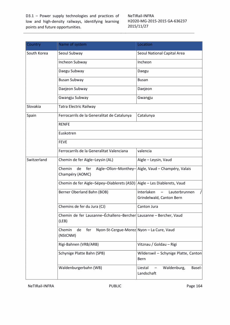
D3.1 – Power supply technologies and practices of
low and high-density railways, identifying learning
points and future opportunities.
NeTIRail-INFRA H2020-MG-2015-2015 GA-636237 2015/11/27
NeTIRail-INFRA PUBLIC Page 164
Country Name of system Location
South Korea Seoul Subway Seoul National Capital Area
Incheon Subway Incheon
Daegu Subway Daegu
Busan Subway Busan
Daejeon Subway Daejeon
Gwangju Subway Gwangju
Slovakia Tatra Electric Railway
Spain Ferrocarrils de la Generalitat de Catalunya Catalunya
RENFE
Euskotren
FEVE
Ferrocarrils de la Generalitat Valenciana valencia
Switzerland Chemin de fer Aigle–Leysin (AL) Aigle – Leysin, Vaud
Chemin de fer Aigle–Ollon–Monthey–
Champéry (AOMC)
Aigle, Vaud – Champéry, Valais
Chemin de fer Aigle–Sépey–Diablerets (ASD) Aigle – Les Diablerets, Vaud
Berner Oberland Bahn (BOB) Interlaken – Lauterbrunnen /
Grindelwald, Canton Bern
Chemins de fer du Jura (CJ) Canton Jura
Chemin de fer Lausanne–Échallens–Bercher
(LEB)
Lausanne – Bercher, Vaud
Chemin de fer Nyon-St-Cergue-Morez
(NStCNM)
Nyon – La Cure, Vaud
Rigi-Bahnen (VRB/ARB) Vitznau / Goldau – Rigi
Schynige Platte Bahn (SPB) Wilderswil – Schynige Platte, Canton
Bern
Waldenburgerbahn (WB) Liestal – Waldenburg, Basel-
Landschaft

D3.1 – Power supply technologies and practices of
low and high-density railways, identifying learning
points and future opportunities.
NeTIRail-INFRA H2020-MG-2015-2015 GA-636237 2015/11/27
NeTIRail-INFRA PUBLIC Page 165
Country Name of system Location
Wengernalpbahn (WAB) Lauterbrunnen – Grindelwald,
Canton Bern
Chemin de fer Aigle–Ollon–Monthey–
Champéry (AOMC)
Aigle, Vaud – Champéry, Valais
Sweden Roslagsbanan Stockholm
Turkey Bursa LRT Bursa
United Kingdom Tyne and Wear Metro Newcastle, Sunderland, Gateshead
and Tyneside
Manchester-Sheffield-Wath Manchester to Sheffield
Manchester, South Junction and Altrincham
Railway
Manchester
Great Eastern Main Line London (Liverpool Street) to
Shenfield (then Chelmsford)
Shildon to Newport County Durham
United States Metra Electric District Service Chicago
Chicago SouthShore and South Bend
Railroad NICTD Line
Northern Indiana & Chicago
Central Link Seattle
4.5 4.6 Electrification system 3 kVdc
Country Name of system Location
Belgium Belgium National Railways (SNCB)
Canada Deux-Montagnes Line Montreal
Czech Republic Czech Railway Infrastructure Administration (SŽDC)
Estonia
Georgia Georgian Railway LLC
Italy RFI - Rete Ferroviaria Italiana (Italian Railways Network)
Latvia Latvian Railways (LDz)

D3.1 – Power supply technologies and practices of
low and high-density railways, identifying learning
points and future opportunities.
NeTIRail-INFRA H2020-MG-2015-2015 GA-636237 2015/11/27
NeTIRail-INFRA PUBLIC Page 166
Country Name of system Location
Luxembourg Chemins de fer luxembourgeois (CFL) The line between Luxembourg and
Arlon
Poland Polish State Railways (PKP)
Russian
Federation
Russian Railways (RZD)
Slovakia Slovak Republic Railways (ŽSR)
Slovenia Slovenian Railways (SŽ)
South Africa Transnet Freight Rail (TFR); MetroRail
Spain Spanish National Railways (RENFE)
Ukraine Ukrainian Railways
United States Morris & Essex Lines New Jersey, lines towards New York
City
4.7 Electrification system 15 kVac/ 16.7 Hz
Country Name of system Location
Austria Austrian Federal Railways
Germany German National Railways
Norway Norwegian National Rail Administration
Sweden Swedish Transport Administration
Switzerland Chemin de fer Bière-Apples-Morges (BAM) Vaud
BLS Canton Bern
Sihltal Zürich Uetliberg Bahn Canton Zürich
Swiss Federal Railways Throughout the country
Zentralbahn Central Switzerland and Bernese
Oberland
4.8 Electrification system 25 kVac/ 50 Hz
Country Name of system Location

D3.1 – Power supply technologies and practices of
low and high-density railways, identifying learning
points and future opportunities.
NeTIRail-INFRA H2020-MG-2015-2015 GA-636237 2015/11/27
NeTIRail-INFRA PUBLIC Page 167
Country Name of system Location
Argentina Ferrocarril General Roca Buenos Aires
Australia Queensland Rail, Citytrain Brisbane, North Coast Line, Coalfields
Transperth Perth
Adelaide Metro Adelaide
Belgium Belgium National Railways (NMBS/SNCB) High-speed lines and some other lines
Bulgaria Bulgarian State Railways BDZ
Croatia Croatian Railways (HŽ) Nationwide
Czech Republic Czech Railway Infrastructure Administration (SŽDC)
Denmark Banedanmark See rail transport in Denmark
Finland Finnish Railway network
France French National Railways (SNCF)
Germany Rübelandbahn Harz
Greece Hellenic Railways Organisation (OSE) Nationwide
Hong Kong Mass Transit Railway Corporation (East
Rail Line) (West Rail Line) and (Ma On Shan
Line)
Hong Kong
Hungary Hungarian State Railways (MÁV) and Raab-Oedenburg-Ebenfurter Eisenbahn AG
(GYSEV)
India Indian Railways (IR)
Delhi Metro Delhi
Israel Israel Railways
Japan JR East Tōhoku, Jōetsu, and Hokuriku Shinkansen
Latvia Latvian Railways (LDz)
Lithuania Lithuanian Railways (LG) Naujoji Vilnia-Kaunas and Naujoji
Vilnia-Trakai
Luxembourg Chemins de fer luxembourgeois (CFL) National standard
Macedonia Macedonian Railways
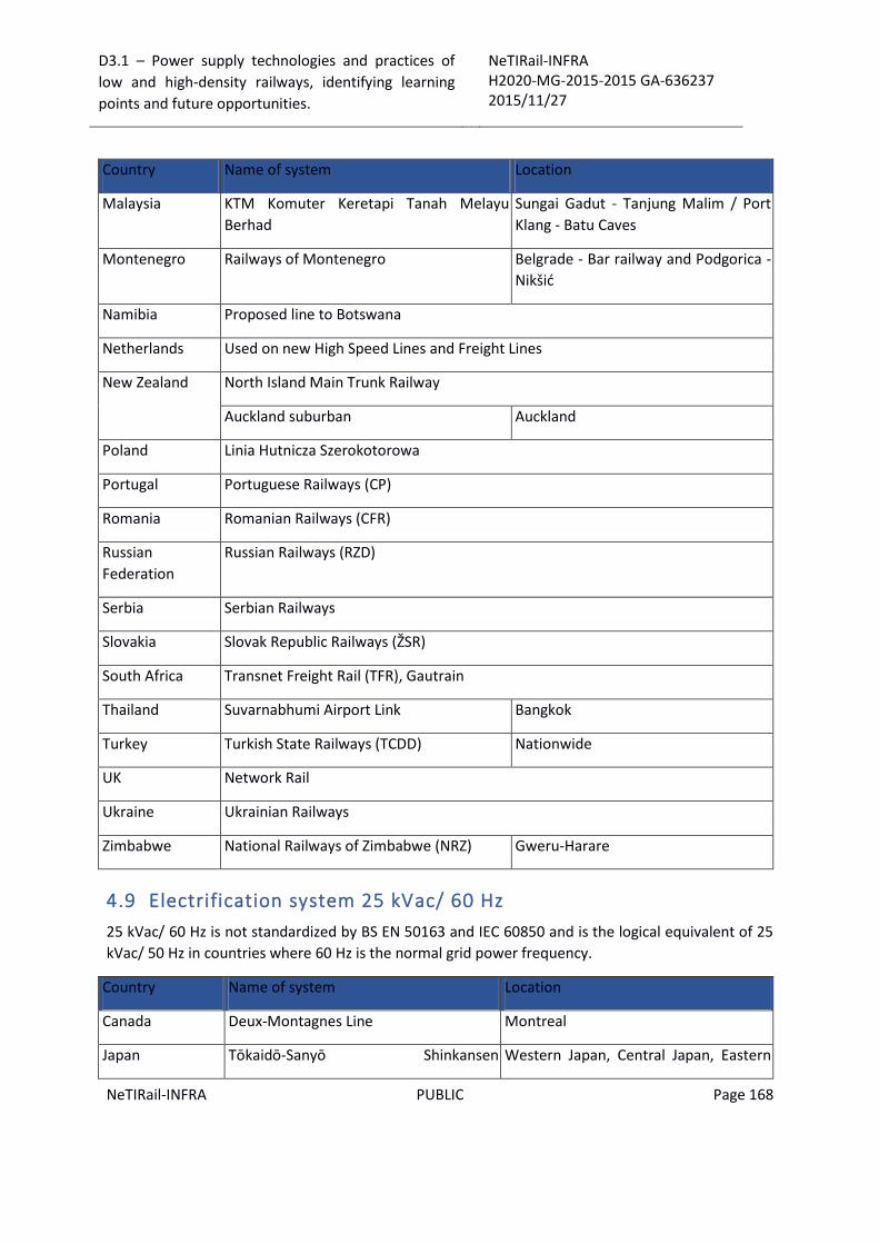
D3.1 – Power supply technologies and practices of
low and high-density railways, identifying learning
points and future opportunities.
NeTIRail-INFRA H2020-MG-2015-2015 GA-636237 2015/11/27
NeTIRail-INFRA PUBLIC Page 168
Country Name of system Location
Malaysia KTM Komuter Keretapi Tanah Melayu
Berhad
Sungai Gadut - Tanjung Malim / Port
Klang - Batu Caves
Montenegro Railways of Montenegro Belgrade - Bar railway and Podgorica -
Nikšić
Namibia Proposed line to Botswana
Netherlands Used on new High Speed Lines and Freight Lines
New Zealand North Island Main Trunk Railway
Auckland suburban Auckland
Poland Linia Hutnicza Szerokotorowa
Portugal Portuguese Railways (CP)
Romania Romanian Railways (CFR)
Russian
Federation
Russian Railways (RZD)
Serbia Serbian Railways
Slovakia Slovak Republic Railways (ŽSR)
South Africa Transnet Freight Rail (TFR), Gautrain
Thailand Suvarnabhumi Airport Link Bangkok
Turkey Turkish State Railways (TCDD) Nationwide
UK Network Rail
Ukraine Ukrainian Railways
Zimbabwe National Railways of Zimbabwe (NRZ) Gweru-Harare
4.9 Electrification system 25 kVac/ 60 Hz
25 kVac/ 60 Hz is not standardized by BS EN 50163 and IEC 60850 and is the logical equivalent of 25
kVac/ 50 Hz in countries where 60 Hz is the normal grid power frequency.
Country Name of system Location
Canada Deux-Montagnes Line Montreal
Japan Tōkaidō-Sanyō Shinkansen Western Japan, Central Japan, Eastern
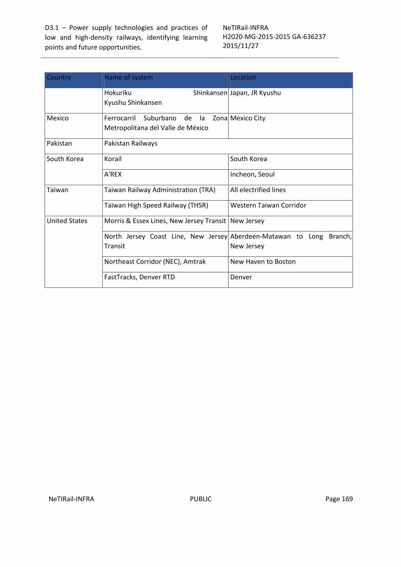
D3.1 – Power supply technologies and practices of
low and high-density railways, identifying learning
points and future opportunities.
NeTIRail-INFRA H2020-MG-2015-2015 GA-636237 2015/11/27
NeTIRail-INFRA PUBLIC Page 169
Country Name of system Location
Hokuriku Shinkansen
Kyushu Shinkansen
Japan, JR Kyushu
Mexico Ferrocarril Suburbano de la Zona
Metropolitana del Valle de México
Mexico City
Pakistan Pakistan Railways
South Korea Korail South Korea
A'REX Incheon, Seoul
Taiwan Taiwan Railway Administration (TRA) All electrified lines
Taiwan High Speed Railway (THSR) Western Taiwan Corridor
United States Morris & Essex Lines, New Jersey Transit New Jersey
North Jersey Coast Line, New Jersey
Transit
Aberdeen-Matawan to Long Branch,
New Jersey
Northeast Corridor (NEC), Amtrak New Haven to Boston
FastTracks, Denver RTD Denver

D3.1 – Power supply technologies and practices of
low and high-density railways, identifying learning
points and future opportunities.
NeTIRail-INFRA H2020-MG-2015-2015 GA-636237 2015/11/27
NeTIRail-INFRA PUBLIC Page 170
5 ANNEX 2: Entities details of database support for analyses for existing power supply installations
This section presents the details of each entity and relationship of them in the database.
Entity “countries”
Columns Summary
Name DataType Constraints Nullable Description
countryID char(2) PK No Primary key or identifier of country
country varchar(150) No Name of country
Relationships
railway_ibfk_2 : Relationship
To railways
Identifying true
On Delete No action
On Update No action
To Multiplicity 0..*
From Multiplicity 1
Sync To Association Yes
Description Ensure the relationship between tables "contries" and "railways" because the
a specific railway belongs a country
overhead_line_power_standards_ibfk_1 : Relationship
To overhead_line_power_standards
Identifying false
On Delete No action

D3.1 – Power supply technologies and practices of
low and high-density railways, identifying learning
points and future opportunities.
NeTIRail-INFRA H2020-MG-2015-2015 GA-636237 2015/11/27
NeTIRail-INFRA PUBLIC Page 171
overhead_line_power_standards_ibfk_1 : Relationship
On Update No action
To Multiplicity 0..*
From Multiplicity 1
Sync To Association Yes
Description Ensure the relationship between tables "contries" and
"overhead_line_power_standards" because analysis of the overhead line
power standards is made belong to a country
Entity “type_lines”
Columns Summary
Name DataType Constraints Nullable Description
line_typeID int(11) PK No Primary key or identifier of line type
line_type varchar(150) No Name of line type
- railway NeTIRail-INFRA line types
(busy passenger, low density
rural/secondary line, and a freight
dominated route)
Relationships
traction_power_supply_characteristics_ibfk_2 : Relationship
To railways
Identifying true
On Delete No action
On Update No action
To Multiplicity 0..*
From Multiplicity 1
Sync To Association Yes

D3.1 – Power supply technologies and practices of
low and high-density railways, identifying learning
points and future opportunities.
NeTIRail-INFRA H2020-MG-2015-2015 GA-636237 2015/11/27
NeTIRail-INFRA PUBLIC Page 172
traction_power_supply_characteristics_ibfk_2 : Relationship
Description Ensure the relationship between tables "type_line" and "railways" because
specific railways shall be a particular type.
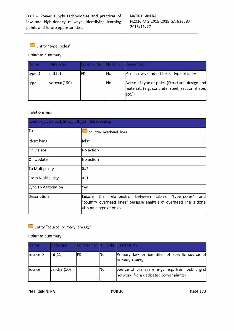
D3.1 – Power supply technologies and practices of
low and high-density railways, identifying learning
points and future opportunities.
NeTIRail-INFRA H2020-MG-2015-2015 GA-636237 2015/11/27
NeTIRail-INFRA PUBLIC Page 173
Entity “type_poles”
Columns Summary
Name DataType Constraints Nullable Description
typeID int(11) PK No Primary key or identifier of type of poles
type varchar(150) No Name of type of poles (Structural design and
materials (e.g. concrete, steel, section shape,
etc.))
Relationships
country_overhead_lines_ibfk_12 : Relationship
To country_overhead_lines
Identifying false
On Delete No action
On Update No action
To Multiplicity 0..*
From Multiplicity 0..1
Sync To Association Yes
Description Ensure the relationship between tables "type_poles" and
"country_overhead_lines" because analysis of overhead line is done
also on a type of poles.
Entity “source_primary_energy”
Columns Summary
Name DataType Constraints Nullable Description
sourceID int(11) PK No Primary key or identifier of specific source of
primary energy
source varchar(50) No Source of primary energy (e.g. from public grid
network, from dedicated power plants)

D3.1 – Power supply technologies and practices of
low and high-density railways, identifying learning
points and future opportunities.
NeTIRail-INFRA H2020-MG-2015-2015 GA-636237 2015/11/27
NeTIRail-INFRA PUBLIC Page 174
Relationships
type_power_supply_systems_ibfk_2 : Relationship
To type_power_supply_systems
Identifying false
On Delete No action
On Update No action
To Multiplicity 0..*
From Multiplicity 1
Sync To Association Yes
Description Ensure the relationship between tables "type_power_supply_systems " and
"source_primary_energy" because analysis of type of power supply system
can be done on a source primary energy
Entity “type_power_supply_systems”
Columns Summary
Name DataType Constraints Nullable Description
typeID int(11) PK No Primary key or identifier of
type of power supply system
type varchar(150) No Name of type of power
supply system
type_generateID int(11) FK
(type_generat
e_energy.typeI
D)
No Foreign key which defines
the type of energy
generated (e.g. thermo,
hydro, nuclear, etc.).
sourceID int(11) FK
(source_prima
ry_energy.sour
ceD)
No Foreign key which defines
the source of energy (e.g.
from public grid network,
from dedicated power
plants)
nominal_voltage int(11) Yes Voltage level for railway
power supply system (DC or
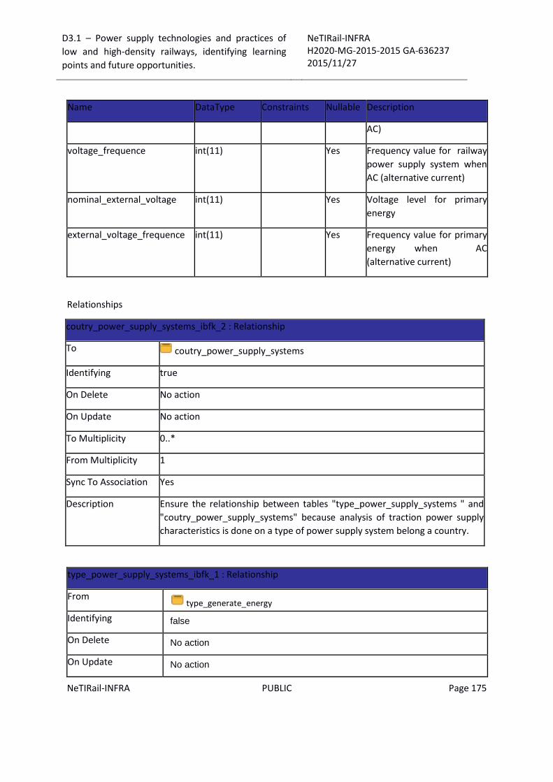
D3.1 – Power supply technologies and practices of
low and high-density railways, identifying learning
points and future opportunities.
NeTIRail-INFRA H2020-MG-2015-2015 GA-636237 2015/11/27
NeTIRail-INFRA PUBLIC Page 175
Name DataType Constraints Nullable Description
AC)
voltage_frequence int(11) Yes Frequency value for railway
power supply system when
AC (alternative current)
nominal_external_voltage int(11) Yes Voltage level for primary
energy
external_voltage_frequence int(11) Yes Frequency value for primary
energy when AC
(alternative current)
Relationships
coutry_power_supply_systems_ibfk_2 : Relationship
To coutry_power_supply_systems
Identifying true
On Delete No action
On Update No action
To Multiplicity 0..*
From Multiplicity 1
Sync To Association Yes
Description Ensure the relationship between tables "type_power_supply_systems " and
"coutry_power_supply_systems" because analysis of traction power supply
characteristics is done on a type of power supply system belong a country.
type_power_supply_systems_ibfk_1 : Relationship
From type_generate_energy
Identifying false
On Delete No action
On Update No action

D3.1 – Power supply technologies and practices of
low and high-density railways, identifying learning
points and future opportunities.
NeTIRail-INFRA H2020-MG-2015-2015 GA-636237 2015/11/27
NeTIRail-INFRA PUBLIC Page 176
type_power_supply_systems_ibfk_1 : Relationship
To Multiplicity 0..*
From Multiplicity 1
Sync To Association Yes
Description Ensure the relationship between tables "type_power_supply_systems” and
"type_generate_energy" because analysis of type of power supply system can
be done on a type generate energy.
type_power_supply_systems_ibfk_2 : Relationship
From source_primary_energy
Identifying false
On Delete No action
On Update No action
To Multiplicity 0..*
From Multiplicity 1
Sync To Association Yes
Description Ensure the relationship between tables "type_power_supply_systems " and "source_primary_energy" because analysis of type of power supply system can be done on a source primary energy
Entity “type_generate_energy”
Columns Summary
Name DataType Constraints Nullable Description
typeID int(11) PK No Primary key or identifier of type of energy
generated
type varchar(150) No Name of type of energy generated (e.g.
thermo, hydro, nuclear, etc.)
Relationships
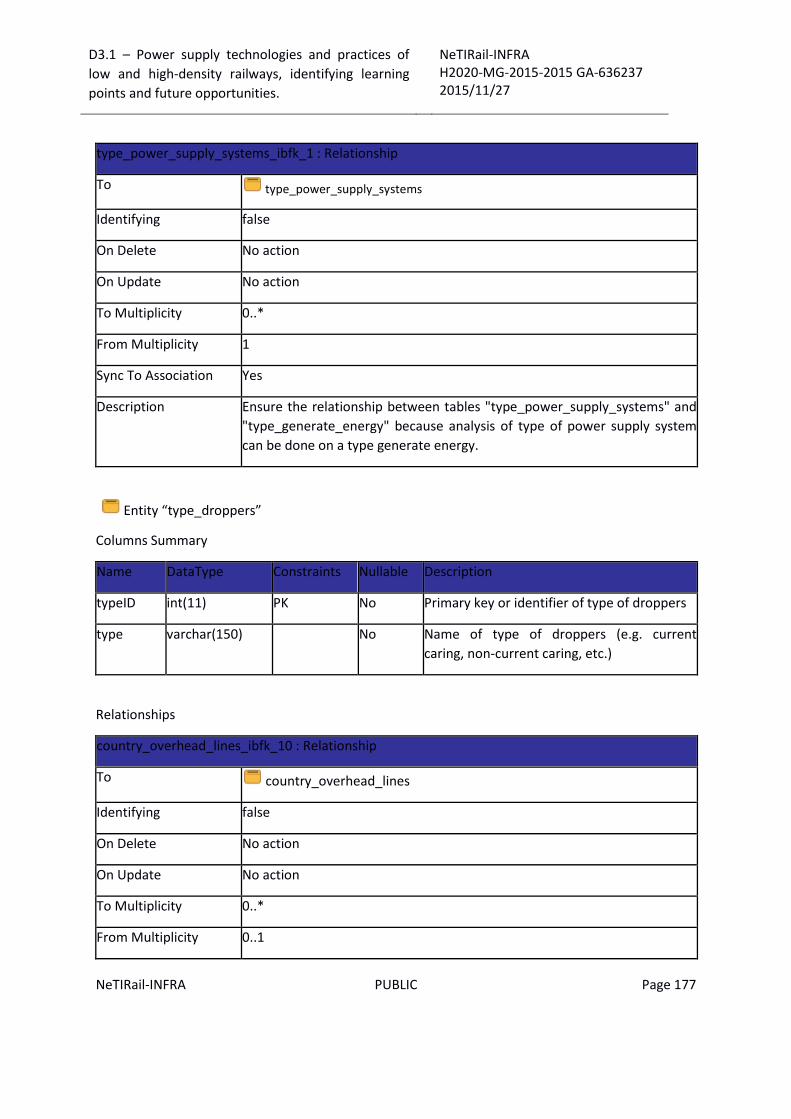
D3.1 – Power supply technologies and practices of
low and high-density railways, identifying learning
points and future opportunities.
NeTIRail-INFRA H2020-MG-2015-2015 GA-636237 2015/11/27
NeTIRail-INFRA PUBLIC Page 177
type_power_supply_systems_ibfk_1 : Relationship
To type_power_supply_systems
Identifying false
On Delete No action
On Update No action
To Multiplicity 0..*
From Multiplicity 1
Sync To Association Yes
Description Ensure the relationship between tables "type_power_supply_systems" and
"type_generate_energy" because analysis of type of power supply system
can be done on a type generate energy.
Entity “type_droppers”
Columns Summary
Name DataType Constraints Nullable Description
typeID int(11) PK No Primary key or identifier of type of droppers
type varchar(150) No Name of type of droppers (e.g. current
caring, non-current caring, etc.)
Relationships
country_overhead_lines_ibfk_10 : Relationship
To country_overhead_lines
Identifying false
On Delete No action
On Update No action
To Multiplicity 0..*
From Multiplicity 0..1

D3.1 – Power supply technologies and practices of
low and high-density railways, identifying learning
points and future opportunities.
NeTIRail-INFRA H2020-MG-2015-2015 GA-636237 2015/11/27
NeTIRail-INFRA PUBLIC Page 178
Sync To Association Yes
Description Ensure the relationship between tables "type_droppers" and
"country_overhead_lines" because analysis of overhead lines can be done
on a type of droppers.
Entity “suspension_types”
Columns Summary
Name DataType Constraints Nullable Description
typeID int(11) PK No Primary key or identifier of type of
suspension
type varchar(150) No Name of type of suspension (e.g. trolley type,
catenary supported type, etc.)
Relationships
country_overhead_lines_ibfk_8 : Relationship
To country_overhead_lines
Identifying false
On Delete No action
On Update No action
To Multiplicity 0..*
From Multiplicity 0..1
Sync To Association Yes
Description Ensure the relationship between tables "suspension_types" and
"country_overhead_lines" because analysis of overhead lines can be done
on a type of suspension.
Entity “type_contact_line”
Columns Summary

D3.1 – Power supply technologies and practices of
low and high-density railways, identifying learning
points and future opportunities.
NeTIRail-INFRA H2020-MG-2015-2015 GA-636237 2015/11/27
NeTIRail-INFRA PUBLIC Page 179
Name DataType Constraints Nullable Description
typeID int(11) PK No Primary key or identifier of contact line
system type
type varchar(150) No Name of contact line system type (e.g.
Overhead contact lines; Conductor third
rail; Overhead conductor rail, etc.)
wire_section int(11) Yes Wire section of contact line
wire_composition varchar(15) Yes Wire composition of contact line
Relationships
country_overhead_lines_ibfk_6 : Relationship
To country_overhead_lines
Identifying true
On Delete No action
On Update No action
To Multiplicity 0..*
From Multiplicity 1
Sync To Association Yes
Description Ensure the relationship between tables "type_contact_line" and
"country_overhead_lines" because analysis of the overhead lines systems is
done also on a type of contact line system.
Entity “type_wire_grade”
Columns Summary
Name DataType Constraints Nullable Description
typeID int(11) PK No Primary key or identifier of type of wire grade
type varchar(150) No Name of type of wire grade (wire
composition material)

D3.1 – Power supply technologies and practices of
low and high-density railways, identifying learning
points and future opportunities.
NeTIRail-INFRA H2020-MG-2015-2015 GA-636237 2015/11/27
NeTIRail-INFRA PUBLIC Page 180
Relationships
country_overhead_lines_ibfk_11 : Relationship
country_overhead_lines_ibfk_4 : Relationship
country_overhead_lines_ibfk_3 : Relationship
To country_overhead_lines
Identifying true
On Delete No action
On Update No action
To Multiplicity 0..*
From Multiplicity 1
Sync To Association Yes
Description Ensure the relationship between tables "type_wire_grade" and
"country_overhead_lines" because analysis of the overhead lines systems is
done also on a type of wire grade suspended or wire grade auxiliary
suspended or dropper wire grade.
Entity “type_tensioning”
Columns Summary
Name DataType Constraints Nullable Description
typeID int(11) PK No Primary key or identifier of tensioning device
type
type_device varchar(150) No Name of tensioning device type (e.g. pulley-
wheel, hydraulic, spring, etc.)
Relationships
country_overhead_lines_ibfk_9 : Relationship
To country_overhead_lines
Identifying false

D3.1 – Power supply technologies and practices of
low and high-density railways, identifying learning
points and future opportunities.
NeTIRail-INFRA H2020-MG-2015-2015 GA-636237 2015/11/27
NeTIRail-INFRA PUBLIC Page 181
country_overhead_lines_ibfk_9 : Relationship
On Delete No action
On Update No action
To Multiplicity 0..*
From Multiplicity 0..1
Sync To Association Yes
Description Ensure the relationship between tables "type_tensioning" and
"country_overhead_lines" because analysis of overhead lines can be done on
a type of tensioning device.
Entity “railways”
Columns Summary
Name DataType Constraints Nullable Description
lineID int(11) PK No Primary key or identifier of specific
railway line
type_lineID int(11) FK
(type_lines.line_t
ypeID)
No Foreign key which defines the type of
railway line
name varchar(150) No Name of railway line
country char(2) FK
(countries.countr
yID)
No Foreign key which defines the country of
railway line
Relationships
country_power_supply_lines_ibfk_1 : Relationship
To country_power_supply_lines
Identifying true
On Delete No action
On Update No action
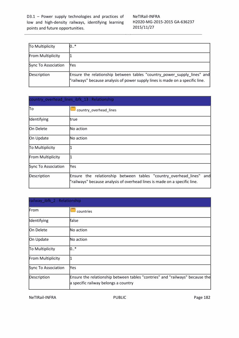
D3.1 – Power supply technologies and practices of
low and high-density railways, identifying learning
points and future opportunities.
NeTIRail-INFRA H2020-MG-2015-2015 GA-636237 2015/11/27
NeTIRail-INFRA PUBLIC Page 182
To Multiplicity 0..*
From Multiplicity 1
Sync To Association Yes
Description Ensure the relationship between tables "country_power_supply_lines" and
"railways" because analysis of power supply lines is made on a specific line.
country_overhead_lines_ibfk_13 : Relationship
To country_overhead_lines
Identifying true
On Delete No action
On Update No action
To Multiplicity 1
From Multiplicity 1
Sync To Association Yes
Description Ensure the relationship between tables "country_overhead_lines" and
"railways" because analysis of overhead lines is made on a specific line.
railway_ibfk_2 : Relationship
From countries
Identifying false
On Delete No action
On Update No action
To Multiplicity 0..*
From Multiplicity 1
Sync To Association Yes
Description Ensure the relationship between tables "contries" and "railways" because the
a specific railway belongs a country

D3.1 – Power supply technologies and practices of
low and high-density railways, identifying learning
points and future opportunities.
NeTIRail-INFRA H2020-MG-2015-2015 GA-636237 2015/11/27
NeTIRail-INFRA PUBLIC Page 183
railway_ibfk_3 : Relationship
From type_lines
Identifying false
On Delete No action
On Update No action
To Multiplicity 0..*
From Multiplicity 1
Sync To Association Yes
Description Ensure the relationship between tables "type_line" and "railways" because
specific railways shall be a particular type.
Entity “country_power_supply_lines”
Columns Summary
Name DataType Constraints Nullable Description
lineID int(11) PK/FK
(railway.lineID) No Composited Primary key for
identifier of specific railways and a
specific type of power supply.
Foreign key which defines of line.
power_supply_typeID int(11) PK/FK
(type_power_su
pply_systems.typ
eID)
No Composited Primary key for
identifier of specific railways and a
specific type of power supply.
Foreign key which defines the type
of power supply.
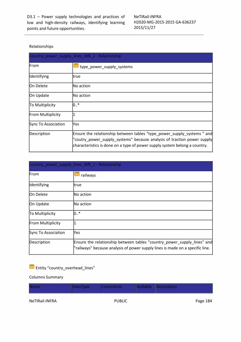
D3.1 – Power supply technologies and practices of
low and high-density railways, identifying learning
points and future opportunities.
NeTIRail-INFRA H2020-MG-2015-2015 GA-636237 2015/11/27
NeTIRail-INFRA PUBLIC Page 184
Relationships
country_power_supply_lines_ibfk_2 : Relationship
From type_power_supply_systems
Identifying true
On Delete No action
On Update No action
To Multiplicity 0..*
From Multiplicity 1
Sync To Association Yes
Description Ensure the relationship between tables "type_power_supply_systems " and
"coutry_power_supply_systems" because analysis of traction power supply
characteristics is done on a type of power supply system belong a country.
country_power_supply_lines_ibfk_1 : Relationship
From railways
Identifying true
On Delete No action
On Update No action
To Multiplicity 0..*
From Multiplicity 1
Sync To Association Yes
Description Ensure the relationship between tables "country_power_supply_lines" and
"railways" because analysis of power supply lines is made on a specific line.
Entity “country_overhead_lines”
Columns Summary
Name DataType Constraints Nullable Description
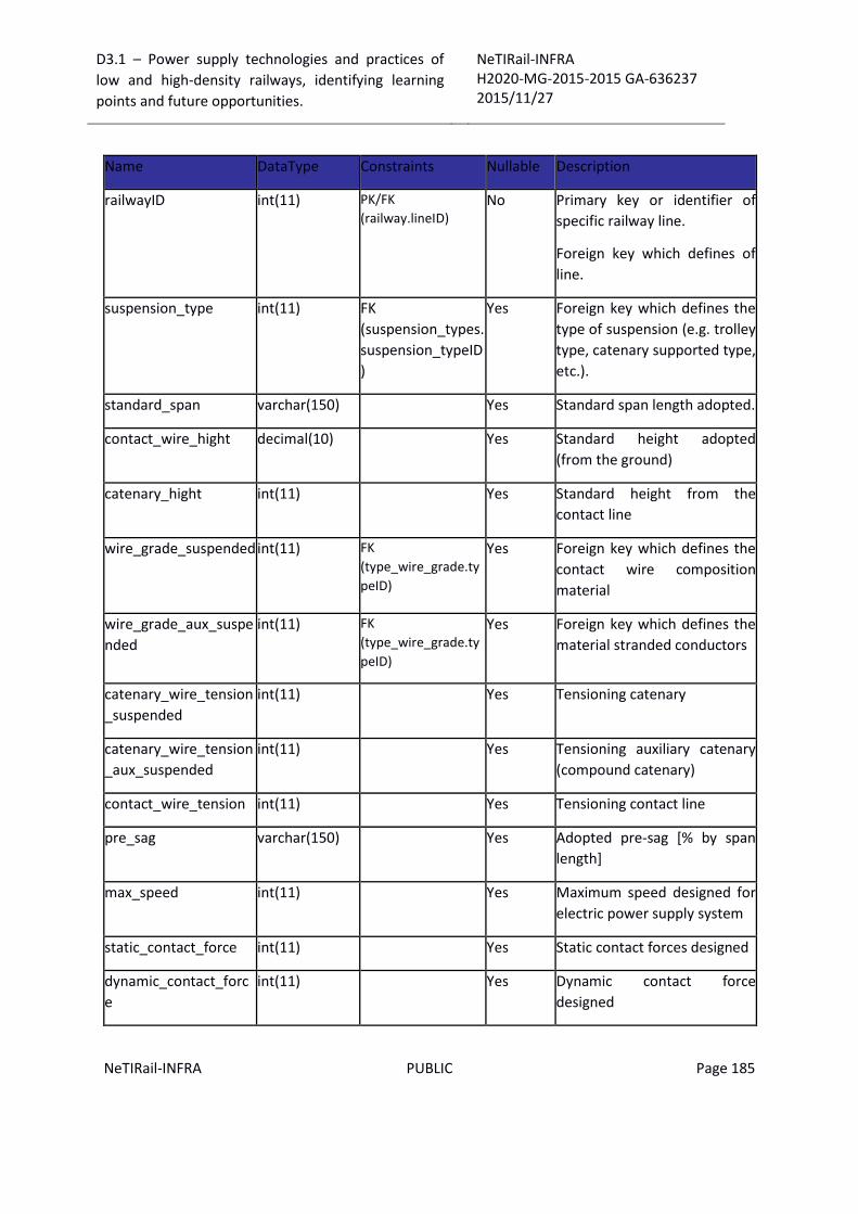
D3.1 – Power supply technologies and practices of
low and high-density railways, identifying learning
points and future opportunities.
NeTIRail-INFRA H2020-MG-2015-2015 GA-636237 2015/11/27
NeTIRail-INFRA PUBLIC Page 185
Name DataType Constraints Nullable Description
railwayID int(11) PK/FK
(railway.lineID) No Primary key or identifier of
specific railway line.
Foreign key which defines of
line.
suspension_type
int(11) FK
(suspension_types.
suspension_typeID
)
Yes Foreign key which defines the
type of suspension (e.g. trolley
type, catenary supported type,
etc.).
standard_span varchar(150) Yes Standard span length adopted.
contact_wire_hight decimal(10) Yes Standard height adopted
(from the ground)
catenary_hight int(11) Yes Standard height from the
contact line
wire_grade_suspended int(11) FK
(type_wire_grade.ty
peID)
Yes Foreign key which defines the
contact wire composition
material
wire_grade_aux_suspe
nded
int(11) FK
(type_wire_grade.ty
peID)
Yes Foreign key which defines the
material stranded conductors
catenary_wire_tension
_suspended
int(11) Yes Tensioning catenary
catenary_wire_tension
_aux_suspended
int(11) Yes Tensioning auxiliary catenary
(compound catenary)
contact_wire_tension int(11) Yes Tensioning contact line
pre_sag varchar(150) Yes Adopted pre-sag [% by span
length]
max_speed int(11) Yes Maximum speed designed for
electric power supply system
static_contact_force int(11) Yes Static contact forces designed
dynamic_contact_forc
e
int(11) Yes Dynamic contact force
designed
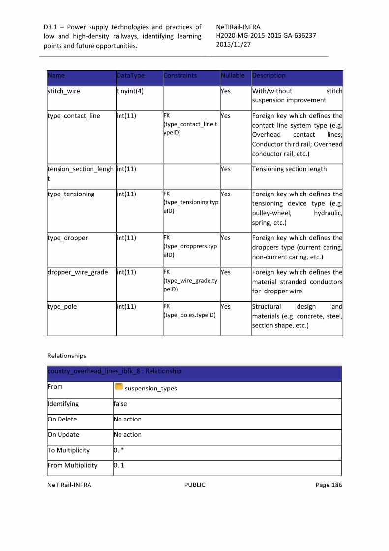
D3.1 – Power supply technologies and practices of
low and high-density railways, identifying learning
points and future opportunities.
NeTIRail-INFRA H2020-MG-2015-2015 GA-636237 2015/11/27
NeTIRail-INFRA PUBLIC Page 186
Name DataType Constraints Nullable Description
stitch_wire tinyint(4) Yes With/without stitch
suspension improvement
type_contact_line int(11) FK
(type_contact_line.t
ypeID)
Yes Foreign key which defines the
contact line system type (e.g.
Overhead contact lines;
Conductor third rail; Overhead
conductor rail, etc.)
tension_section_lengh
t
int(11) Yes Tensioning section length
type_tensioning int(11) FK
(type_tensioning.typ
eID)
Yes Foreign key which defines the
tensioning device type (e.g.
pulley-wheel, hydraulic,
spring, etc.)
type_dropper int(11) FK
(type_dropprers.typ
eID)
Yes Foreign key which defines the
droppers type (current caring,
non-current caring, etc.)
dropper_wire_grade int(11) FK
(type_wire_grade.ty
peID)
Yes Foreign key which defines the
material stranded conductors
for dropper wire
type_pole int(11) FK
(type_poles.typeID) Yes Structural design and
materials (e.g. concrete, steel,
section shape, etc.)
Relationships
country_overhead_lines_ibfk_8 : Relationship
From suspension_types
Identifying false
On Delete No action
On Update No action
To Multiplicity 0..*
From Multiplicity 0..1

D3.1 – Power supply technologies and practices of
low and high-density railways, identifying learning
points and future opportunities.
NeTIRail-INFRA H2020-MG-2015-2015 GA-636237 2015/11/27
NeTIRail-INFRA PUBLIC Page 187
country_overhead_lines_ibfk_8 : Relationship
Sync To Association Yes
Description Ensure the relationship between tables "suspension_types" and
"country_overhead_lines" because analysis of overhead lines can be done on
a type of suspension.
country_overhead_lines_ibfk_12 : Relationship
From type_poles
Identifying false
On Delete No action
On Update No action
To Multiplicity 0..*
From Multiplicity 0..1
Sync To Association Yes
Description Ensure the relationship between tables "type_poles" and
"country_overhead_lines" because analysis of overhead line is done also on a
type of poles.
country_overhead_lines_ibfk_10 : Relationship
From type_dropprers
Identifying false
On Delete No action
On Update No action
To Multiplicity 0..*
From Multiplicity 0..1
Sync To Association Yes
Description Ensure the relationship between tables "type_droppers" and
"country_overhead_lines" because analysis of overhead lines can be done on

D3.1 – Power supply technologies and practices of
low and high-density railways, identifying learning
points and future opportunities.
NeTIRail-INFRA H2020-MG-2015-2015 GA-636237 2015/11/27
NeTIRail-INFRA PUBLIC Page 188
country_overhead_lines_ibfk_10 : Relationship
a type of droppers.
country_overhead_lines_ibfk_11 : Relationship
country_overhead_lines_ibfk_4 : Relationship
country_overhead_lines_ibfk_3 : Relationship
From type_wire_grade
Identifying false
On Delete No action
On Update No action
To Multiplicity 0..*
From Multiplicity 0..1
Sync To Association Yes
Description Ensure the relationship between tables "type_wire_grade" and
"country_overhead_lines" because analysis of the overhead lines systems is
done also on a type of wire grade suspended or wire grade auxiliary
suspended or dropper wire grade.
country_overhead_lines_ibfk_6 : Relationship
From type_contact_line
Identifying false
On Delete No action
On Update No action
To Multiplicity 0..*
From Multiplicity 0..1
Sync To Association Yes
Description Ensure the relationship between tables "type_contact_line" and
"country_overhead_lines" because analysis of the overhead lines systems is
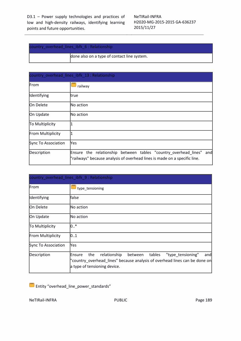
D3.1 – Power supply technologies and practices of
low and high-density railways, identifying learning
points and future opportunities.
NeTIRail-INFRA H2020-MG-2015-2015 GA-636237 2015/11/27
NeTIRail-INFRA PUBLIC Page 189
country_overhead_lines_ibfk_6 : Relationship
done also on a type of contact line system.
country_overhead_lines_ibfk_13 : Relationship
From railway
Identifying true
On Delete No action
On Update No action
To Multiplicity 1
From Multiplicity 1
Sync To Association Yes
Description Ensure the relationship between tables "country_overhead_lines" and
"railways" because analysis of overhead lines is made on a specific line.
country_overhead_lines_ibfk_9 : Relationship
From type_tensioning
Identifying false
On Delete No action
On Update No action
To Multiplicity 0..*
From Multiplicity 0..1
Sync To Association Yes
Description Ensure the relationship between tables "type_tensioning" and
"country_overhead_lines" because analysis of overhead lines can be done on
a type of tensioning device.
Entity “overhead_line_power_standards”

D3.1 – Power supply technologies and practices of
low and high-density railways, identifying learning
points and future opportunities.
NeTIRail-INFRA H2020-MG-2015-2015 GA-636237 2015/11/27
NeTIRail-INFRA PUBLIC Page 190
Columns Summary
Name DataType Constraints Nullable Description
standardID varchar(150) PK No Primary key or identifier of
catenary type
countryID char(2) FK (countries.countryID) No Foreign key which defines the
country to which it belongs
standard
name varchar(255) Standard name
description varchar(255) No Standard description
web_references varchar(255) No Web references
Relationships
overhead_line_power_standards_ibfk_1 : Relationship
From countries
Identifying false
On Delete No action
On Update No action
To Multiplicity 0..*
From Multiplicity 1
Sync To Association Yes
Description Ensure the relationship between tables "overhead_line_power_standards"
and "countries" because analysis of overhead line power standard belong to a
country