deliverable d4.2 test plan document - cordis · 4.5 scenarios a and b emulation ... (working draft)...
TRANSCRIPT

CoRaSat
COgnitiveRAdioforSATelliteCommunications
FP7-ICT
CollaborativeProject-GrantAgreementno.:316779
Collaborativeproject
DeliverableD4.2TestPlanDocument
Projectacronym: CoRaSatProjectfulltitle: COgnitiveRAdioforSATelliteCommunicationsGrantagreementno: 316779Projectwebsite: www.ict-corasat.eu
DeliverableNo. D4.2
DeliveryDate M30
WorkPackageNo. WP4 WorkPackageTitle: CoRaSat Test andDemonstration
Authors(Partner)(perBeneficiary,ifmorethanoneBeneficiaryprovideittogether)
MostafaPakparvar,JoelGrotz(Newtec)
EvaLagunas,SymeonChatzinotas,SinaMaleki,ShreeSharma(UniLuxembourg)
BarryEvans,PaulThompson(UniSurrey)
AlessandroGuidotti,DanieleTarchi,AlessandroVanelli-Coralli,VincenzoIcolari,GiovanniE.Corazza,CarloCaini(UniBologna)
Status(F:final;D:draft;RD:reviseddraft): F
Disseminationlevel:
(PU = Public; PP = Restricted to other program
participants;RE=Restrictedtoagroupspecifiedby
the consortium;CO = Confidential, only for
membersoftheconsortium.
PU
NTC CoRaSat_Del_D4_2_r1_v0.doc
Projectstartdateandduration 01October2012,36month

Release0.06(Workingdraft) pag.2of38
INTENTIONALLY LEFT BLANK
ICT−316779CoRaSat DeliverableD4.2
Release0.06(Workingdraft) pag.3of38
TA B L E O F CO N T E N T S 1 EXECUTIVE SUMMARY ............................................................................................................................. 5
2 SCOPE AND STRUCTURE OF THE DOCUMENT .................................................................................. 6
3 TEST PLATFORM INTERFACES AND PARAMETERS ........................................................................ 7
3.1 TEST PLATFORM - HARDWARE SETUP ........................................................................................................ 83.2 PARAMETERS RECORDED DURING THE MEASUREMENTS ............................................................................. 9
3.2.1 Configure Terminal Interface ........................................................................................................... 133.2.2 Configure Channel Emulator Interface ............................................................................................ 143.2.3 Configure SatNet Configurations Interface ...................................................................................... 15
4 DEMONSTRATION USE CASES .............................................................................................................. 17
4.1 SELECTED CONFIGURATION SCENARIO FOR SCENARIOS A AND B ............................................................. 184.2 SELECTED CONFIGURATION SCENARIO FOR SCENARIO C .......................................................................... 184.3 TEST CONTROL INTERFACE OF THE COMBINED 8 TEST-CASES .................................................................. 194.4 CONFIGURATION ....................................................................................................................................... 204.5 SCENARIOS A AND B EMULATION ............................................................................................................. 204.6 SCENARIO C EMULATION .......................................................................................................................... 21
5 TEST PLAN ................................................................................................................................................... 23
5.1 TEST CASE #1: INSTALLATION/DEPLOYMENT OF A NETWORK OF TERMINALS WITHIN A COGNITIVE ZONE 235.2 TEST CASE #2: CHANGE NETWORK CONFIGURATION OF THE FSS TERMINAL IN THE PRESENCE OF
INCUMBENT USER LINK INTERFERENCE ............................................................................................................... 235.3 TEST CASE #3: MEASURE NETWORK EFFICIENCY WITH AND WITHOUT RA TECHNIQUE USAGE ................ 245.4 TEST CASE #4: DETECT INTERFERENCE PRESENT FROM INCUMBENT USER ON THE FORWARD LINK .......... 245.5 TEST CASE #5: CHANGE THE FORWARD LINK CARRIER CAPACITY ALLOCATION ACCORDING TO
INCUMBENT USER INTERFERENCE PRESENCE ...................................................................................................... 255.6 TEST CASE #6: MEASURE THE INTERFERENCE LEVELS FROM CONFIGURED FSS SYSTEM ON THE RETURN
LINK AT THE FS RECEIVER INPUT ........................................................................................................................ 255.7 TEST CASE #7: CHANGE THE RETURN LINK CARRIER FREQUENCY, POWER, RATE ACCORDING TO
INCUMBENT USER ................................................................................................................................................ 255.8 TEST CASE #8: (OPTIONAL) TEST ESOMP MOVEMENT THROUGH THE EMULATED ENVIRONMENT OF THE
INCUMBENT INTERFERENCE ................................................................................................................................ 26
6 TEST PROCEDURE ..................................................................................................................................... 27
6.1 TEST PROCEDURE #1 - INSTALLATION/DEPLOYMENT OF A NETWORK OF TERMINALS WITHIN A COGNITIVE
ZONE 276.2 TEST PROCEDURE #2 – CHANGE NETWORK CONFIGURATION OF FSS TERMINAL IN INCUMBENT USER LINK
INTERFERENCE PRESENCE ................................................................................................................................... 286.3 TEST PROCEDURE #3 – MEASURE NETWORK EFFICIENCY WITH AND WITHOUT RA TECHNIQUE ............... 286.4 TEST PROCEDURE #4 - DETECT INTERFERENCE PRESENT FROM INCUMBENT USER ON THE FORWARD LINK
296.5 TEST PROCEDURE #5 - CHANGE THE FORWARD LINK CARRIER CAPACITY ALLOCATION ACCORDING TO
INCUMBENT USER INTERFERENCE PRESENCE ...................................................................................................... 296.6 TEST PROCEDURE #6 - MEASURE THE INTERFERENCE LEVELS FROM CONFIGURED FSS SYSTEM ON THE
RETURN LINK AT THE FS RECEIVER INPUT .......................................................................................................... 30
ICT−316779CoRaSat DeliverableD4.2
Release0.06(Workingdraft) pag.4of38
6.7 TEST PROCEDURE #7 - CHANGE THE RETURN LINK CARRIER FREQUENCY, POWER, RATE ACCORDING TO
INCUMBENT USER ................................................................................................................................................ 306.8 TEST PROCEDURE #8 - (OPTIONAL) TEST ESOMP MOVEMENT THROUGH THE EMULATED ENVIRONMENT
OF THE INCUMBENT INTERFERENCE .................................................................................................................... 31
7 CONCLUSIONS AND NEXT STEPS ......................................................................................................... 32
8 DEFINITION, SYMBOLS AND ABBREVIATIONS ............................................................................... 33
9 DOCUMENT HISTORY .............................................................................................................................. 35
10 APPENDIX: TEST SETUP CALIBRATION .......................................................................................... 36
10.1 METHODOLOGY ...................................................................................................................................... 3610.2 EXAMPLE ................................................................................................................................................ 38

ICT−316779CoRaSat DeliverableD4.2
Release0.06(Workingdraft) pag.5of38
1 EX E C U T I V E SU M M A R Y The aim of WP4 is the demonstration and validation of the CoRaSat concept through testbed implementation of the selected scenarios in a laboratory environment. This deliverable, namely D4.2 “Test Plan Document,” aims at providing a detailed description of the tests executed in the context of this project, as well as the test procedures. These tests are executed on the demonstration platform defined on the basis of the storyboards provided in D4.1 and the test platform reported in D4.3. Therefore, this deliverable shall be considered along with D4.1 and D4.3, as, together, they provide the overall context in which the scenarios identified in the CoRaSat project will be demonstrated.
For this purpose, we follow the set of defined storyboard cases provided in D4.1 and define all of the required input and output parameters for the test platform.
The defined procedures serve as basis for the formal testing, which is subsequently reported in D4.5, “Formal Test Demonstration”. This is then used to test the defined cognitive techniques as proposed within WP3 and as adapted to the demonstration platform within WP4.
The overall testplan is then executed and the results of the executed tests in this document are reported in D4.4 “Integration and Testing” document, as well as the D4.5 formal test document.

ICT−316779CoRaSat DeliverableD4.2
Release0.06(Workingdraft) pag.6of38
2 SC O P E A N D ST R U C T U R E O F T H E DO C U M E N T This document describes and details the test plan of the demonstration setup platform of the CoRaSat demonstrator. The storyboard has been defined in document D4.1 and this document further outlines the tests to be executed, following the defined use cases of the storyboard document. In particular, the incumbent and cognitive system representations are provided, together with the channel emulator that includes incumbent, cognitive, and interference channels. Moreover, the interference detection by the cognitive channel and the network response is considered.
A subsequent test procedure (detailed execution plan) is defined as a consequence of this testplan.
In this deliverable, the key performance indicators and metrics defined in the CoRaSat context are linked to the measured values in the laboratory setup.
The document is organized as follows.
In Chapter 3, the input and output parameters are defined and their usage on the current test platform is described together with the resulting measurement points exploited to verify the test outcome.
In Chapter 4, the use cases are summarized and the end-to-end test scenarios are explained. These are based on D4.1, which contains 8 scenarios that are outlined in more details and in a step-by-step test approach, explaining all intermediate steps for the tests.
In Chapter 5, the detailed test plan is outlined in a step-by-step manner: the tests are described with input and output parameters, and the relation to the key performance indicators is provided.
Chapter 6 outlines the test procedure and the instrumentation parameters are defined for each test case.
In Chapter 7, the outline of the following work is described and the conditions of the testing as well as expected outcome are depicted.

ICT−316779CoRaSat DeliverableD4.2
Release0.06(Workingdraft) pag.7of38
3 TE S T PL A T F O R M IN T E R F A C E S A N D PA R A M E T E R S The test setup details are described in D4.3. All of the sub-components and hardware used in the test setup are defined in this document. In the following, the resulting input/output parameters by the test equipment and the measurement points are defined.
The test platform provides, for each test case, the following interfaces and measurement points, which are read and configured by the test control PC.
The overall parameters from the equipment in the test-plan are listed in Table 1, while Figure 1 illustrates the CoRaSat demonstration test setup elements.
Table 1 - Emulation of the CoRaSat setup elements used for the tests.
Terminal 1-8
ST-01 to ST-08
Channel Emulator
CHe
Gateway Emulator
GWe
Database Emulator
DBe
Terminal locations (latitude, longitude elevation)
Traffic Allocation FWD and RTN link
Allocate 8 terminals to FWD1 / FWD2
Allocate 8 terminals to carriers on return link
RTN1 / RTN2
Configured link attenuation for 8 return links
Configure SNR levels for the 8 return link
Configure Interference levels for the 8 return links
Configure 8 terminal rates forward and return link
Configure the surrounding interference of incumbent users for scenarios A, B and C.
Figure 1 - Illustration of the CoRaSat demonstration test setup elements.

ICT−316779CoRaSat DeliverableD4.2
Release0.06(Workingdraft) pag.8of38
3.1 Test Platform - Hardware Setup The hardware setup consists two racks of equipment, which include the elements in Table 2.
Table 2 - List of hardware setup test platform equipment.
Equipment Number of units Remark
Channel Emulator 8 port
Programmable and configurable 3
Specifically setup for the CoRaSat test setup to emulate signal, interference on the forward and return for 8 terminals.
Terminals MDM3300 with standard software (no modifications)
8 Standard terminals, no specific changes.
IP Switch/Router 24 ports 2 Standard switches with no specific changes.
Channel control PC/server
With specific software to control the emulator 1
Dedicated control PC with specific CoRaSat software to control the 8 channel emulator attenuator settings.
Traffic test server 2
Specific traffic server for this setup. Standard server equipment with dedicated specific configuration and software.
Hub demodulators MCD6000 2 One on each SatNet
(one per carrier group)
Hub controller server
Server group for all hub related controller software
1 Standard product equipment with no special changes for the setup.
CoRaSat control PC
Running specific software for User Interface and CoRaSat controller emulator
1
Dedicated CoRaSat control PC with control software, user interface and emulation of the devised cognitive techniques, including DB, RA, SS-SNIR techniques.
Database server emulator 1 Dedicated, specific server running an SQL database with data from UNIS for the selected geographic area.
Hub modulator for forward links 2 Standard equipment for the forward link transmission.
Hub edge router for traffic and management and control traffic
1 Standard equipment for the IP data and control plane routing and traffic handling.
FS link emulator
(MDM6000 equipment with standard software) 1
Standard equipment with no special changes used to emulate the transmit interference levels.

ICT−316779CoRaSat DeliverableD4.2
Release0.06(Workingdraft) pag.9of38
Satellite channel emulator
For satellite link emulation 2
Specifically developed satellite channel emulator (running on an MDM6000 hardware with specific Add-on board). Emulates delay and satellite non-linearity and filtering.
Spectrum Analyzer for FS link receiver emulation
1 Standard spectrum analyzer equipment connected to the test setup.
Splitters, combiners, noise source injection and specific cabling and setup for forward and return link L-band connectivity
1 Standard cabling and signal routing equipment.
Racks for equipment housing 2 Standard rack equipment.
3.2 Parameters recorded during the measurements The following lists all the data recorded during the lab testing. Specific intermediate and final results are computed, which is also mentioned explicitly in Table 3.
Table 3 - List of link parameters for the CoRaSat test platform control and monitoring.
Parameter Type Description
Return link parameters
C/N [dB] Return link measured C/N at the demodulator input.
The C/N is a measured value at the demodulator input to the hub. The measurement is collected by the CoRaSat control server.
RxLevel [dBm] Receive level at the demodulator input.
The receive level is measured at the hub demodulator input and collected by the CoRaSat control server.
Central Frequency [MHz]
Center frequency of all return link carriers of the 8 terminals in MHz.
The emulated uplink RF frequency is shown.
The central frequency for each return link carrier is configured by the HRC/MxDMA controller (not CoRaSat) and is read by the CoRaSat server for information and tracking only. No specific configuration is performed: this is done by the HRC/MxDMA server only.
Errored Seconds Counter on the return link side that indicates decoding errors occurring on a per-second count basis.
Count of errored seconds, resulting from CRC checks in the demodulator at the hub input.
Bit Rate [bps] Return link channel bitrate for each of the logged On 8 terminals.
The bitrate indicates the instantaneous channel bitrate and can
ICT−316779CoRaSat DeliverableD4.2
Release0.06(Workingdraft) pag.10of38
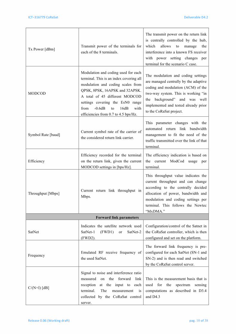
Tx Power [dBm] Transmit power of the terminals for each of the 8 terminals.
The transmit power on the return link is centrally controlled by the hub, which allows to manage the interference into a known FS receiver with power setting changes per terminal for the scenario C case.
MODCOD
Modulation and coding used for each terminal. This is an index covering all modulation and coding scales from QPSK, 8PSK, 16APSK and 32APSK. A total of 45 different MODCOD settings covering the EsN0 range from -0.6dB to 16dB with efficiencies from 0.7 to 4.5 bps/Hz.
The modulation and coding settings are managed centrally by the adaptive coding and modulation (ACM) of the two-way system. This is working “in the background” and was well implemented and tested already prior to the CoRaSat project.
Symbol Rate [baud] Current symbol rate of the carrier of the considered return link carrier.
This parameter changes with the automated return link bandwidth management to fit the need of the traffic transmitted over the link of that terminal.
Efficiency Efficiency recorded for the terminal on the return link, given the current MODCOD settings in [bps/Hz].
The efficiency indication is based on the current ModCod usage per terminal.
Throughput [Mbps] Current return link throughput in Mbps.
This throughput value indicates the current throughput and can change according to the centrally decided allocation of power, bandwidth and modulation and coding settings per terminal. This follows the Newtec “MxDMA.”
Forward link parameters
SatNet Indicates the satellite network used SatNet-1 (FWD1) or SatNet-2 (FWD2).
Configuration/control of the Satnet in the CoRaSat controller, which is then configured and set on the platform.
Frequency Emulated RF receive frequency of the used SatNet.
The forward link frequency is pre-configured for each SatNet (SN-1 and SN-2) and is then read and switched by the CoRaSat control server.
C/(N+I) [dB]
Signal to noise and interference ratio measured on the forward link reception at the input to each terminal. The measurement is collected by the CoRaSat control server.
This is the measurement basis that is used for the spectrum sensing computations as described in D3.4 and D4.3

ICT−316779CoRaSat DeliverableD4.2
Release0.06(Workingdraft) pag.11of38
C/N .exp [dB]
Expected C/N level at the input to each terminal based on link budget calculations for the emulated terminals.
This value is used in the SS-SNIR method as outlined D3.4 and D4.3
C/(N+I).lta [dB]
Computed long term average (moving average over several seconds) with the value for the C/(N+I) measured.
This value is taken into account in the SS-SNIR method as described D3.4 and D4.3
RxLevel [dBm]
Receive level measured in the input for the eight terminals. The measurement on each terminal input is collected by the CoRaSat control server.
This value is used to measure the input receive level and is used in the SS-SNIR method as described D3.4 and D4.3
RxLevel.lta [dBm] Long-term average of the receive level. The LTA is computed in the CoRaSat control server.
Long-term average of the receive level used in the SS-SNIR method as defined in the SS-SNIR method description in D3.4 and D4.3.
ModCod
Index of the modulation and coding used in the forward link (based on DVB-S2 MODCODs), ranging over the QPSK, 8PSK, 16APSK, 32APSK range.
The ModCod settings on the forward link are set by the ACM mechanism of the forward link. This is running in “background” in the context of the CoRaSat demo setup and keeps the links up even under varying and low SNRs.
Mean Efficiency [bps/Hz] Efficiency of the forward link in [bps/Hz] for the range considered.
The mean efficiency is used to measure the forward link capacity of the setup and is used as metric of the system capacity.
Symbol Rate [Kbaud] Configuration of the forward link symbol rate in Kbaud.
The symbol rate on the forward link is configured in the forward link system. This is a basic setting, and is taken into account by the CoRaSat control server as occupied bandwidth only for the interference assessment.
C/I DB [dB]
Expected (computed) C/I value from the database value measurement of the interference level and combined with the link budget value for the signal.
The database assessed interference impact is used to configure the terminals to either forward link (SatNet-1 or SatNet-2). The overall impact of all terrestrial interference is taken into account. The CoRaSat control server computes these values.

ICT−316779CoRaSat DeliverableD4.2
Release0.06(Workingdraft) pag.12of38
C/I SS [dB]
Signal to interference ratio resulting from the spectrum sensing with the usage of the C/(N+I) measurement at the terminal input and the comparison to the link budget expected value.
The C/I estimate is based on the computation resulting from the C/(N+I) measurement value and the link budget estimates of the C/N.exp value.
Interference [dBW/ BW in MHz]
Computed interference level as resulting from reading the database and as computed by integration of all interference contributions over the carrier bandwidth.
This interference level is the basis for the computation of the database based C/I DB value, which is subsequently used to control the channel settings for the emulation of the link.
Throughput
Measured throughput of the forward link “iperf” process that is running at IP level to verify the link connectivity and performance.
The forward link throughput per terminal is assessed on the basis of the end-to-end IP traffic passing through the link and this is measured on the connected traffic test servers on either side (behind the terminal and behind the hub).
All these control and monitoring parameters are managed and controlled through a centralized user interface for the CoRaSat setup specifically.
Figure 2 illustrates the user interface for this setup. Three panels that access the terminal configuration, the channel configuration, or the SatNet configuration are present. The geographic context is also illustrated on Figure 2.
The selection of the forward link channel over the simulated detailed area is selectable and configured over the link.

ICT−316779CoRaSat DeliverableD4.2
Release0.06(Workingdraft) pag.13of38
Figure 2 - User interface for the test platform control and monitoring.
3.2.1 Configure Terminal Interface
The terminal configuration foresees to define all provisioned terminal parameters such as those reported in Table 4.
Table 4 - Terminal configuration.
Terminal parameter Comment / Unit
Latitude FSS Earth station emulated latitude in degrees North
Longitude FSS Earth station emulated longitude in degrees East
Iperf traffic forward link
Enable IP traffic from traffic server (connected to the hub) to traffic client (behind the modem)
10Mbps IP UDP traffic configured in Best Effort mode
ICT−316779CoRaSat DeliverableD4.2
Release0.06(Workingdraft) pag.14of38
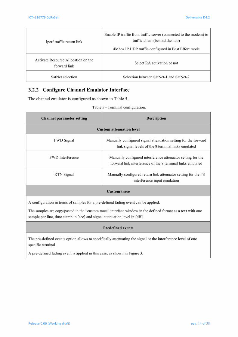
Iperf traffic return link
Enable IP traffic from traffic server (connected to the modem) to traffic client (behind the hub)
4Mbps IP UDP traffic configured in Best Effort mode
Activate Resource Allocation on the forward link
Select RA activation or not
SatNet selection Selection between SatNet-1 and SatNet-2
3.2.2 Configure Channel Emulator Interface
The channel emulator is configured as shown in Table 5.
Table 5 - Terminal configuration.
Channel parameter setting Description
Custom attenuation level
FWD Signal Manually configured signal attenuation setting for the forward link signal levels of the 8 terminal links emulated
FWD Interference Manually configured interference attenuator setting for the forward link interference of the 8 terminal links emulated
RTN Signal Manually configured return link attenuator setting for the FS interference input emulation
Custom trace
A configuration in terms of samples for a pre-defined fading event can be applied.
The samples are copy/pasted in the “custom trace” interface window in the defined format as a text with one sample per line, time stamp in [sec] and signal attenuation level in [dB].
Predefined events
The pre-defined events option allows to specifically attenuating the signal or the interference level of one specific terminal.
A pre-defined fading event is applied in this case, as shown in Figure 3.

ICT−316779CoRaSat DeliverableD4.2
Release0.06(Workingdraft) pag.15of38
Figure 3 - Heavy rainfade time series example.
3.2.3 Configure SatNet Configurations Interface
The SatNet configuration interface foresees the configuration of the forward link satellite network configuration for each of the 8 terminals in the emulation network.
A specific forward link frequency is selected. A pre-defined 30Mbaud link is applied for the forward link. The following table summarizes the emulated center frequencies.
Table 6 - Forward link emulated carriers’ center frequencies.
Carrier number RF center frequency [MHz]
1 17731.5
2 17794.5
3 17857.5
4 17920.5
5 17983.5
6 18046.5
7 18109.5
8 18172.5
9 18235.5
10 18298.5
11 18361.5

ICT−316779CoRaSat DeliverableD4.2
Release0.06(Workingdraft) pag.16of38
12 18424.5
13 18487.5
14 18550.5
15 18613.5
16 18676.5
17 18739.5
18 18802.5
19 18865.5
20 18928.5
21
Exclusive band option
19.7-20.2 GHz
No FS interference
Each of the SatNet configurations can be configured to either of these settings to emulate different contexts.
The configuration then emulates the environment for the defined geographical area and the interference context for that carrier at the defined terminal location.
The interference context is illustrated on the user interface and each terminal interference level is indicated on the interface as well.

ICT−316779CoRaSat DeliverableD4.2
Release0.06(Workingdraft) pag.17of38
4 DE M O N S T R A T I O N US E CA S E S The use cases are defined in D4.1 and, in the following, we review the use cases in more details. The impact on the different elements of the test platform is also taken into account.
Table 7 - Considered test cases following the storyboard defined.
Use case Description Configuration used Test procedure used
0 Calibration test.
Defined channel configuration and measurement of FWD and RTN link configuration calibrations.
Test procedure #1
1 Installation/deployment of a network of terminals within a cognitive zone.
Selected Configuration environment for scenario A / B.
Test procedure #1
2 Change network configuration of FSS terminal in incumbent user link interference presence.
Selected Configuration environment for scenario A / B.
Test procedure #2
3 Measure network efficiency with and without RA technique usage.
Selected Configuration environment for scenario A / B.
Test procedure #3
4 Detect interference present from incumbent user on the forward link.
Selected Configuration environment for scenario A / B.
Test procedure #4
5
Change the forward link carrier capacity allocation according to incumbent user interference presence.
Selected Configuration environment for scenario A / B.
Test procedure #5
6 Measure the interference levels from configured FSS system on the return link at the FS receiver input.
Selected Configuration environment for scenario C.
Test procedure #6
7 Change the return link carrier frequency, power, rate according to incumbent user.
Selected Configuration environment for scenario C.
Test procedure #7
8
OPTIONAL: ESOMP TEST Test ESOMP movement through the emulated environment of the incumbent interference.
Selected Configuration environment for scenario A / B & C.
Test procedure #8

ICT−316779CoRaSat DeliverableD4.2
Release0.06(Workingdraft) pag.18of38
4.1 Selected configuration scenario for scenarios A and B A geographical area with BSS feeder links and FS link presence is emulated in the [17.3-19.7] GHz band using geographic and interference data from the same area.
Figure 4 - Emulated interference context for the scenario A and B. The 8 FSS terminals are assumed in the context of a real computed FS link interference computed for scenario B [17.7-19.7GHz] for a defined
geographic location.
The assumed area in this case is the greater London area in the UK, which is relatively dense in terms of FS links and therefore represents an interesting geographic context to emulate. The emulation grid precision was chosen to be 1km x 1km in this context.
The channels within the forward link contexts to be emulated can be selected so that a defined interference context is emulated, which is of relevance for the cases to study.
Figure 5 - Illustration of the signal and interference computation for the emulated terminal locations.
4.2 Selected configuration scenario for scenario C A geographical area with an FS link presence is emulated in the [27.5-29.5] GHz band. The FS receiver location is defined, as well as the terminals transmitting on the return link.
The overall link between the terminals and the FS receiver station is then computed and emulated.

ICT−316779CoRaSat DeliverableD4.2
Release0.06(Workingdraft) pag.19of38
The 8 return link interferences of the terminals in the potential vicinity of the FS link receiver are emulated via the interference links Interf_1 to Interf_8 and combined at the assumed location of the FS link receiver in a spectrum analyzer representing the FS link receiver input.
Figure 6 - Emulated context for the scenario C with N=8 terminals.
4.3 Test Control Interface of the combined 8 test-cases The Graphical User Interface (GUI) concisely integrates all the functionalities stipulated in D 4.1 into a window with separate views for terminal configuration and channel emulation.
Figure 7 - CoRaSat demonstrator main window, which is used for the execution of the presented test plan.

ICT−316779CoRaSat DeliverableD4.2
Release0.06(Workingdraft) pag.20of38
4.4 Configuration The 8 terminals are emulating a position within a defined geographic context. Two SatNets (different forward links) are configured to connect the terminals to the platform with in addition the return carrier group (RCG) configured such that.
The following figure illustrates the configuration of the two used SatNets as well as the emulated frequency plan. The principle is that two separate forward and return link carriers and carrier groups are used to emulate the two-way end-to-end service. The overall system is allocating the individual terminals to either the forward carrier FWD1 or FWD2, depending on its assignment for the overall link.
The control and management is centralized in the CoRaSat control PC emulation that assigns the terminals to the different forward links according to the requirements of the link.
Figure 8 - Configuration contexts of the test platform.
4.5 Scenarios A and B emulation Scenarios A and B are emulated via the forward link emulation path. This includes a separate forward link for the exclusive and non-exclusive part of the spectrum.
Each of the eight terminals is configurable in signal power level, interference level and noise level at reception, individually.
Table 8 - Emulation steps followed for the scenario A and B related tests.
Step Description
#1 Determine the FSS terminal locations.
#2 Select the FS link interference context by choosing the forward link frequency and bandwidth.
#3 Select the SatNet / FWD link allocation of the terminals and the service profiles for the terminals (e.g., 10Mbps / 4Mbps).
#4 Configure the traffic emulation, IP traffic in forward and return links.
#5
Configure the Channel emulator On the channel emulator page:
• Press Reset and Apply to start the channel emulator from a known calibrated configuration.
• Press Load Interf values à Loads the corresponding interference emulation settings to the attenuators for the link evaluation.
• Press Apply à start the emulation of the forward link settings for the signal, noise and interference at all the 8 terminal emulated positions.

ICT−316779CoRaSat DeliverableD4.2
Release0.06(Workingdraft) pag.21of38
#6
On the Configure Terminals interface: • Record forward link parameters and link performance results. • Refresh parameters and read the expected C/I from the database evaluation. • The overall efficiency is evaluated for the forward link and per terminal. • Record the terminal link parameters, including:
o Signal power level expected form link calculations. o Interference levels expected form link calculations. o C/(N+I) measured on the terminal forward link reception. o C/N expected from link budget calculations. o Test data recording, including IP throughput per terminal. o Efficiency recording, including ModCod.
The following figure illustrates the emulated reception condition at the input of each terminal for one particular forward link considered.
Figure 9 - Ratios for signal, interference, and noise configurations for the 8 emulated terminals.
4.6 Scenario C emulation Scenario C is emulated via configurable links on the return link that adapt to the computed interference link to the FS receiver emulated. Scenario C link emulation is performed along the steps provided in Table 9.
Table 9 - Emulation steps followed for the scenario C related tests.
Step Description
#1
Configure the FSS terminal location
Configure the terminals to the defined location of the FSS terminals.
Ensure traffic at defined rate is running and measure the throughput of the 8 terminals.
#2 Configure the FS link receiver location
The FS receiver location is configured (Lat/Long).
#3
Compute the expected link attenuation between FSS transmitter and FS receiver
This is done automatically for the line of sight (LOS) attenuation expected given the Lat/Long positions of the terminals and the FS receiver.
#4
Apply return link channel settings in emulator
These are calculated automatically based on the assessment of the line-of-sight between the FSS earth station locations and the FS link receiver, taking into account the antenna gains as well.
#5 Measure aggregate power density at the FS receiver input
Measure [dBW/Hz] limitation at FS receiver input.

ICT−316779CoRaSat DeliverableD4.2
Release0.06(Workingdraft) pag.22of38
#6 Perform return link RA / DCA adaptation to adjust to max. return link power limit
Verify that the required FS link limitation is respected as required.
#7
Measure observed power density at FS receiver location
This power measurement is performed on the spectrum analyzer that emulates the location of the FS receiver.
ICT−316779CoRaSat DeliverableD4.2
Release0.06(Workingdraft) pag.23of38
5 TE S T PL A N In the following, we review the 8 defined storyboard use cases and detail the test plan for each case. The specific parameters for the equipment configuration are then outlined in the following chapter.
5.1 Test case #1: Installation/deployment of a network of terminals within a cognitive zone
The goal of this test case is to verify that the emulation of terminal locations within the coverage area is credible. After the terminals are arbitrarily provisioned, the verification is done by comparing the signal, interference levels, and terminal throughputs with expected values. A successful execution of this test case implies that the end-to-end connectivity emulation facilitated by the NTC CoRaSat platform is useful and relevant for the purpose of emulating an end-to-end satellite communication empowered by cognitive radio techniques. A step-by-step guideline of all test cases is delineated in the following.
1. All terminals are provisioned, the expected EsN0 is then known and can be determined for all terminals.
2. From the database reading we can access the expected interference levels at all terminal locations.
3. Then we compute the impact of the interference on all links based on the expected EsN0 and the interference levels at all locations of the terminals.
4. From this result, the terminal signal and interference links are emulated.
5. The overall forward link efficiency is noted for reference.
6. The “Resource Allocation” (RA) procedure on the forward link is triggered, changing the terminals potentially to the SatNet-2 (Forward link without interference on exclusive band).
7. The average forward link efficiency should be improved accordingly, the terminals within the cognitive zones are correctly moved to the exclusive frequency band.
An aggregate interference is emulated and takes into account the aggregated effect from all the FS interference for the emulation of the interference effect at the 8 terminal locations.
All terminals are configured for a defined SatNet-1 or SatNet-2 (Forward link frequency 1 or 2). The interference from the emulated locations are taken into account and configured in the channel emulator.
The database interaction, the interference computation (verified and correct combined level) as well as the correct assessment of the expected signal to interference ratio for each terminal on the SN-1 and SN-2 is demonstrated with this test.
This is the basis for the database access (DB) and the DCA on the forward link, configuring two independent SatNets SN-1 and SN-2.
5.2 Test case #2: Change network configuration of the FSS terminal in the presence of incumbent user link interference
The purpose of this test case is to verify the functionality of the DB <> NCC technique for tackling the incumbent user interference. To this end, the terminals are provisioned initially similar to test case #1. Subsequently, we deliberately modify/add some entries in the database in such a way that a number of

ICT−316779CoRaSat DeliverableD4.2
Release0.06(Workingdraft) pag.24of38
terminals end up in cognitive zones. The test case would be successful if the NCC correctly changes the configuration of the corresponding terminals in response to new interference conditions.
The following steps are executed for test case #2:
1. Configure terminals in network.
2. Enable the FS interference.
3. Verify end-to-end link performance.
4. Change the forward link assignments to adapt to the FS interference, if terminals logout.
5. Change the emulated FS interference for one or several terminals.
6. Measure the impact on the network and the link performance.
5.3 Test case #3: Measure network efficiency with and without RA technique usage
The Resource Allocation (RA) technique has been already described in detail in D3.3. In this test case, both forward and return link performance is assessed when the RA technique is incorporated by the NCC and the results will be used to evaluate the gain compared to the same scenario without using the RA where the resources are allocated randomly without any sort of decision making. This test case is an integration of test cases 5 and 7, which will be explained later.
The following steps are executed for test case #3:
1. Follow the steps as defined in test sequence #2.
2. Execute the RA (resource allocation) on the forward link for each configuration step.
3. Measure the allocation efficiency and the resulting efficiency on the average FWD and RTN link.
5.4 Test case #4: Detect interference present from incumbent user on the forward link
Knowledge of the interference in the context of CoRaSat is obtained either by querying the database or by dedicated spectrum sensing capability of the platform. The latter detects interference by monitoring the received signal power and SNR and comparing them to the long-term averages and expected values. The comparison will result in a deduction clarifying the status of the channel: whether there is channel fading, or there is interference, or the condition is normal. In the current test case, the deductions should be the same as the artificial cause of the phenomenon that has been introduced to the channel emulator deliberately to verify the performance of the spectrum sensing.
The following steps are executed for test case #4:
1. Follow the steps as defined in test sequence #2.
2. Chang the interference level on the forward link manually, to emulate an unknown interference source.
3. Verify that the spectrum sensing (SS-SNIR) method is well detecting the interference.
4. Measure the allocation efficiency and the resulting efficiency on the average FWD and RTN link.
ICT−316779CoRaSat DeliverableD4.2
Release0.06(Workingdraft) pag.25of38
5.5 Test case #5: Change the forward link carrier capacity allocation according to incumbent user interference presence
This test case entails the realization of the RA functionality at the forward link. After the provisioning of the terminals, the NCC will steer the terminals to switch to one of the available FWD1 and FWD2 links by a decision that seeks optimum occupation of the spectrum given the current interference presence which in turn results in optimization of the overall performance.
The following steps are executed for test case #5:
1. Follow the steps as defined in test sequence #4.
2. Measure the overall efficiency and efficiency per terminal.
3. Reallocate the interfered terminal to the other forward link to improve efficiency.
4. Measure the overall efficiency and efficiency per terminal.
5.6 Test case #6: Measure the interference levels from configured FSS system on the return link at the FS receiver input
This test case makes sure that regardless of incorporating RA at the return link, the interference level sensed at the FS receiver input is kept below the permitted bound. This is easily verified by using a measurement device at the location of the FS receiver.
The following sequence is followed for this test execution:
1. Configure two to three terminals in the direct vicinity of the assumed FS receiver location; this needs to be done manually and so close that sufficient interference can be emulated into the FS receiver input.
2. Update the return link attenuators so that the emulated interference environment is reflecting the geographic context assumed.
3. Measure the interference input on the return link spectrum analyzer.
5.7 Test case #7: Change the return link carrier frequency, power, rate according to incumbent user
The RA mechanism in the return link is generally similar to that of the forward link in a sense that both mechanisms aim at allocating resources by principals of water filling. However, the RA task in return link is more sophisticated due to the larger number of mutable parameters and the fact that the interference caused by the return link at the location of the FS receivers should be kept minimal. Thus, in this test case we will show that the NCC is capable of maintaining both tasks simultaneously.
1. The following sequence is followed for this test execution:
2. Execute the sequence of test cases #6.
3. Measure the interference impact.
4. Verify the return link throughput and bitrate per terminal.
5. Apply the return link resource allocation (RA) method.
6. Verify the allocated resources and the resulting return link efficiency.
7. Measure via the spectrum analyzer the impact on the incumbent users.
ICT−316779CoRaSat DeliverableD4.2
Release0.06(Workingdraft) pag.26of38
5.8 Test case #8: (optional) Test ESOMP movement through the emulated environment of the incumbent interference
For the ESOMP measurements, the procedure to be followed is that a sequence of discrete locations emulating the ESOMP movement along a specific line is followed, which then also shows how the terminal reacts along the line of different locations within the ESOMP movement.
The ESOMP test is performed by applying a gradual stepping over the location of a terminal and update along the linear stepping the parameter reading and applying the configuration changes. The forward and return link configurations are updated along the ESOMP stepping and the resulting.
The following procedure is followed for the ESOMP testing:
1. Perform a change of the position of the terminal e.g. ST-01 in Latitude or Longitude steps of 0.1deg (1km).
2. Apply the interference context of the forward link for that new position.
3. Verify the terminals connectivity in terms of forward link throughput.
4. Verify the FS interference impact on the terminal reception.
5. Verify/record that the forward link throughput is reaching the defined level as required.
6. Under severe interference conditions, apply the RA and change the frequency allocation of the terminal.
7. Verify the FWD link switching along the ESOMP emulated movement and the resulting.

ICT−316779CoRaSat DeliverableD4.2
Release0.06(Workingdraft) pag.27of38
6 TE S T PR O C E D U R E The following section lists the test procedures in more details as they are executed on the test platform for the defined test cases. For each test procedure, the user interface for the test setup is used. All parameters for the test execution and the monitoring are all defined through the user interface for the CoRaSat test setup.
6.1 Test procedure #1 - Installation/deployment of a network of terminals within a cognitive zone
Context: Scenarios A and B.
Cognitive technique tested: Database (DB) access.
Table 10 - Test procedure #1.
Step Procedure
#1 Configure the default initial configuration for the GWe and terminal locations latitude and longitude.
#2 Emulate a defined geographical situation with terminal positions defined on the map of the emulated locations.
Define expected terminal signal and signal to noise ratio levels on FWD and RTN.
#3 Compute the forward link budgets for the satellite links and the incumbent interference links to the dominant interferer on the forward link.
#4 Compute the return-link link budgets for the emulation return link to the dominant FS link receiver for scenario C.
#5 Configure the 3 channel emulators for the noise level on the forward link, the interference level on the forward link and the interference levels on the return link for the scenario B FS receiver input.
#6 Unlock the terminals so that they logon.
#7 Interact with database emulator (NCC <>DBe) to determine assignments of the terminals to the FWD1 / FWD2 and RTN1 / RTN2 capacity.
#8 Measure terminal signal and SNIR levels.
Measure terminal throughput.
#9 Compare the measured terminal performance with expected results.
#10 Measure the overall forward link efficiency of the link.
#11
Record terminal and link statistics, including.
C/(N+I) measured on all terminals on the forward link reception.
C/N expected form link budget computations at emulated location.
Receive power measured.
Expected receive power.
Estimated C/I values.

ICT−316779CoRaSat DeliverableD4.2
Release0.06(Workingdraft) pag.28of38
6.2 Test procedure #2 – Change network configuration of FSS terminal in incumbent user link interference presence
Context: Scenarios A and B (forward link).
Cognitive method tested: DB forward link with changes.
Table 11 - Test procedure #2.
Step Procedure
#1 Prepare the setup following the steps along the procedure #1.
#2 Change DB interference context and verify link
Change the interference level of one terminal and verify that the link is reacting to the change.
#3 Measure the changed efficiency per terminal
Record the new ModCod and efficiency settings per terminal
#4 Record key performance results
Record the efficiency, ModCod and throughput per terminal
6.3 Test procedure #3 – Measure network efficiency with and without RA technique
Context: Scenarios A and B (forward link).
Cognitive method tested: RA in forward link.
Table 12 - Test procedure #3.
Step Procedure
#1 Perform test steps of procedure #1.
#2
Record the initial state when the terminals are interfered with FS link interference as emulated from the considered context
Record the link performance per terminal and for the overall average of the forward link and return link efficiencies.
#3 Perform the RA method for the forward link
Use the Resource Allocation (RA) method to allocate the 8 terminals to the selected SatNet given the interference context measured.
#4 Perform DCA forward link reconfiguration
Perform the switch of the SatNet allocation.
#5 Measure KPI (efficiency) for the reconfigured forward link
When terminals are all back online, measure the efficiency per terminal and for the overall network.
#6 Record IP throughput measurements for all terminals

ICT−316779CoRaSat DeliverableD4.2
Release0.06(Workingdraft) pag.29of38
6.4 Test procedure #4 - Detect interference present from incumbent user on the forward link
Context: Scenarios A and B (forward link).
Cognitive method tested: SS-SNIR in forward link.
Table 13 - Test procedure #4.
Step Procedure
#1 Setup link and terminal locations
Follow the setup steps from procedure #1..
#2 Note link performance
Verify and note the link throughput and efficiency of the forward link.
#3 Change manually the interference of one or several terminals
Manually change the interference for one or several terminals by 3dB (increase) to see if the SS-SNIR method is detecting the interference presence.
#4 Wait for several seconds and verify that the SS-SNIR detection is working
Verify the SS-SNIR indication for the emulated interference terminals and measure the C/I level as deduced from the SS-SNIR method.
#5 Reset test setup and channel emulator
Revert to the initial condition for the test as defined in step 1.
#6 Prepare a fading event emulation for the same terminal
For the same terminals, emulate a fading event and verify that the SS-SNIR method does not interpret the fading event as interference.
#7 Fading event emulation
Wait for the duration of the fading event and verify the “fading event” indicator” for the terminal.
#8 Record terminal link statistics
Record the end-to-end link statistics to verify that the service is well running and performing as expected.
6.5 Test procedure #5 - Change the forward link carrier capacity allocation according to incumbent user interference presence
Context: Scenarios A and B (forward link).
Cognitive method tested: Resource Allocation (RA) in forward link.
Table 14 - Test procedure #5.
Step Procedure
#1 Configure the terminals and the emulated geographic context
Follow initial setup steps as defined in procedure #1.
#2 Increase interference emulated at specific terminals

ICT−316779CoRaSat DeliverableD4.2
Release0.06(Workingdraft) pag.30of38
Manually change the interference emulated at different FSS terminal locations, i.e. increase by about 3dB the interference levels..
#3 Measure impact on the end-to-end link performance
Record the end-to-end link performance and efficiency of the terminals.
#4 Perform a Resource Allocation (RA) step on the forward link
Verify that the RA is well identifying the potential change of the terminal allocation as an improved efficiency configuration.
#5 Change back the interference impact
Remove the additional emulated interference assumed and revert to the initial settings of the emulated scenario.
#6 Perform again the Resource Allocation (RA) step
Verify that the RA procedure reverts to the previous resource allocation of terminals/SatNet configurations.
6.6 Test procedure #6 - Measure the interference levels from configured FSS system on the return link at the FS receiver input
Context: Scenario C (return link).
Cognitive method tested: Resource Allocation (RA) in return link.
Table 15 - Test procedure #6.
Step Procedure
#1 Setup the FS interference context on the channel emulator
#2 Measure the interference impact on the FS link receiver
#3 Compare the interference impact to the applicable limitations
#4 Perform the reconfiguration of the return link to adapt to the defined limitations
6.7 Test procedure #7 - Change the return link carrier frequency, power, rate according to incumbent user
Context: Scenario C (return link).
Cognitive method tested: Resource Allocation (RA) in return link.
Table 16 - Test procedure #7.
Step Procedure
#1 Setup the scenario C interference context as defined in procedure #6
#2 Measure the link performance of all FSS terminals
Record the bandwidth allocation on the return link.
#3 Measure the FS receiver interference impact of all the terminals
#4 Perform the return link Resource Allocation (RA) procedure

ICT−316779CoRaSat DeliverableD4.2
Release0.06(Workingdraft) pag.31of38
#5 Verify the FS receiver impact and the interference limit constraint
#6 Measure the allocated bandwidth on the return link
6.8 Test procedure #8 - (optional) Test ESOMP movement through the emulated environment of the incumbent interference
Context: Scenarios A, B, and C (return link).
Cognitive method tested: Database (DB) access for forward link, Resource Allocation (RA) in forward link and return link.
Table 17 - Test procedure #8.
Step Procedure
#1 Define a sequence of consecutive locations for the ESMOP movement
#2 Configure one terminal to the next location
#3 Measure the link performance in forward and return link
#4 Measure the interference impact in forward and return link
#5 Verify the impact on the FS receiver in the vicinity
#6 Perform RA in forward and return link
#7 Repeat steps as of 2 for the sequence of defined ESOMP intermediate positions
The parameters measured on the different equipment are listed in Table 18.
Table 18 -Measured parameters on the different equipment.
ST-01 – ST-08 GWe NCC FS receiver emulator
Efficiency
SNIR
Signal Power
Bandwidth
Configured FWD and RTN capacity / terminal
Allocated configurations terminals / Forward and Return links (FWD1/FWD2) and (RTN1/RTN2)
Aggregate efficiency for the forward and return link
Interference power density in dBW/MHz
In addition to these measurements, a Spectrum Analyzer is used to verify the signal power at the input of the FS receiver for the scenario C return-link emulation.

ICT−316779CoRaSat DeliverableD4.2
Release0.06(Workingdraft) pag.32of38
7 CO N C L U S I O N S A N D NE X T ST E P S The test plans and procedures for the storyboard scenarios defined in D4.1 are described in this document. The test platform setup is described in D4.1 and D4.3, which define, together with the present deliverable, the demonstration and test plan context for the CoRaSat project.
The execution of the tests is performed along the procedures defined in this document for the foreseen test setup.
The defined KPIs are directly related to the performance metrics defined within the project:
• Overall system level efficiency.
• Guaranteed service level per satellite terminal transmission.
• Respect of the interference limitations to the FS receivers.
All of these performance metrics are measured directly on the system in a live test setup with the equipment and measurement setup as described in the document.
The test procedure is followed and all configurations and test parameters recorded and saved during the procedure. With this it is ensured that all results are well reproducible.
The digital set of configurations and results constitutes the test results presented as outcome of the project work package 4, in combination with the lab test setup.
The execution of the test plans is then performed and the summary conclusions are reported in D4.5 within WP4 of the CoRaSat project.
The test setup is also demonstrated and presented to the project reviewers.

ICT−316779CoRaSat DeliverableD4.2
Release0.06(Workingdraft) pag.33of38
8 DE F I N I T I O N, SY M B O L S A N D AB B R E V I A T I O N S ACM Adaptive Coding and Modulation
AUPC Automated Uplink Power Control
ACI Adjacent Channel Interference
CE Channel Emulator
CQI Channel Quality Information
CR Cognitive Radio
CS Compressive Sensing
CSI Channel State Information
CENELEC Centre for Electro Technical Standards
DB Database
DCA Dynamic Capacity Allocation
DVB Digital Video Broadcasting
DVB-RCS DVB with Return Channel via Satellite
DVB-S DVB via Satellite
DVB-S2X DVB via Satellite version 2 extension
EBU European Broadcasting Union
ETSI European Telecommunications Standards Institute
E-UTRAN Evolved UMTS Terrestrial Radio Access Network (a.k.a LTE)
FC Fusion Center
GWe Gateway Emulator
HRC High Resolution Coding
IA Interference Alignment
IC Interference Cartography
IDW Inverse Distance Weighted
LRT Likelihood-Ratio Test
LTE Long Term Evolution
LTE-A LTE Advanced
MAC Medium Access Control
MIMO Multiple Input Multiple Output
MODCOD Modulation and (channel) Coding
MxDMA Multi-dimensional dynamic medium access
NCC Network Control Centre
RA Resource Allocation
REM Radio Environment Map
RCST RCS subscriber
RF Radio Frequency
RLC Radio Link Control
RSS Received Signal Strength
ST Satellite Terminal
ICT−316779CoRaSat DeliverableD4.2
Release0.06(Workingdraft) pag.34of38
SS-SNIR Spectrum Sensing SNIR
SNIR Signal to noise and interference ratio
SIN Satellite Interactive Network

ICT−316779CoRaSat DeliverableD4.2
Release0.06(Workingdraft) pag.35of38
9 DO C U M E N T HI S T O R Y
Rel. version Date Change Status Author 1 0 30/09/2015 First release to the European Commission NTC

ICT−316779CoRaSat DeliverableD4.2
Release0.06(Workingdraft) pag.36of38
10 AP P E N D I X : TE S T S E T U P C A L I B R A T I O N In order to calibrate the test setup in position and reference level for the interference to the location of the test, Newtec and the University of Surrey performed a detailed assessment.
This appendix presents results of analysis of the impact of the UK FS links at 18 GHz into an FSS receiver at a specific geographic location by using the interference matrix files generated by the University of Surrey.
10.1 Methodology To determine the interference into a FSS terminal at a chosen location a number of steps need to be performed to get the interference aggregate in the appropriate bandwidth. The aggregate interference will be determined as a Power Spectral Density in the FSS carrier occupied bandwidth in dBW/Occ BW at the LNA/LNB input.
Step 1
Determine the FSS receiver centre frequency (GHz) and occupied bandwidth (MHz) at the geographic location of interest for the satellite longitude of interest.
Step 2
Calculate the lower and upper frequencies of the FSS carrier.
OCC lo = FSSfreq – FSSbw/1000/2
OCC hi = FSSfreq + FSSbw/1000/2
Step 3
For the geographic location of interest obtain the interference parameters from the appropriate interference matrix file.
For each interfering carrier in the appropriate row (record) do the following. a) CalculatethelowerandupperfrequenciesofeachFSinterferingcarrier. INTlo=FSfreq–FSbw/1000/2 INThi=FSfreq+FSbw/1000/2b) DeterminetheFSS/FSoverlapinMHz(OVLAPBW)usingthefollowingprocedure.SeeFigure10.
CASE 1
If ((INT lo <= OCC lo) and (INT hi >= OCC hi)) then OVLAP BW = (OCC hi – OCC lo) * 1000
CASE 2
If (INT hi <= OCC lo) then OVLAP BW = 0
CASE 3
If (INT lo>= OCC hi) then OVLAP BW = 0
OVLAP BW = 0.0
CASE 4
If ((INT lo >= OCC lo) and (INT hi <= OCC hi)) then OVLAP BW = (INT hi – INT lo) * 1000
ICT−316779CoRaSat DeliverableD4.2
Release0.06(Workingdraft) pag.37of38
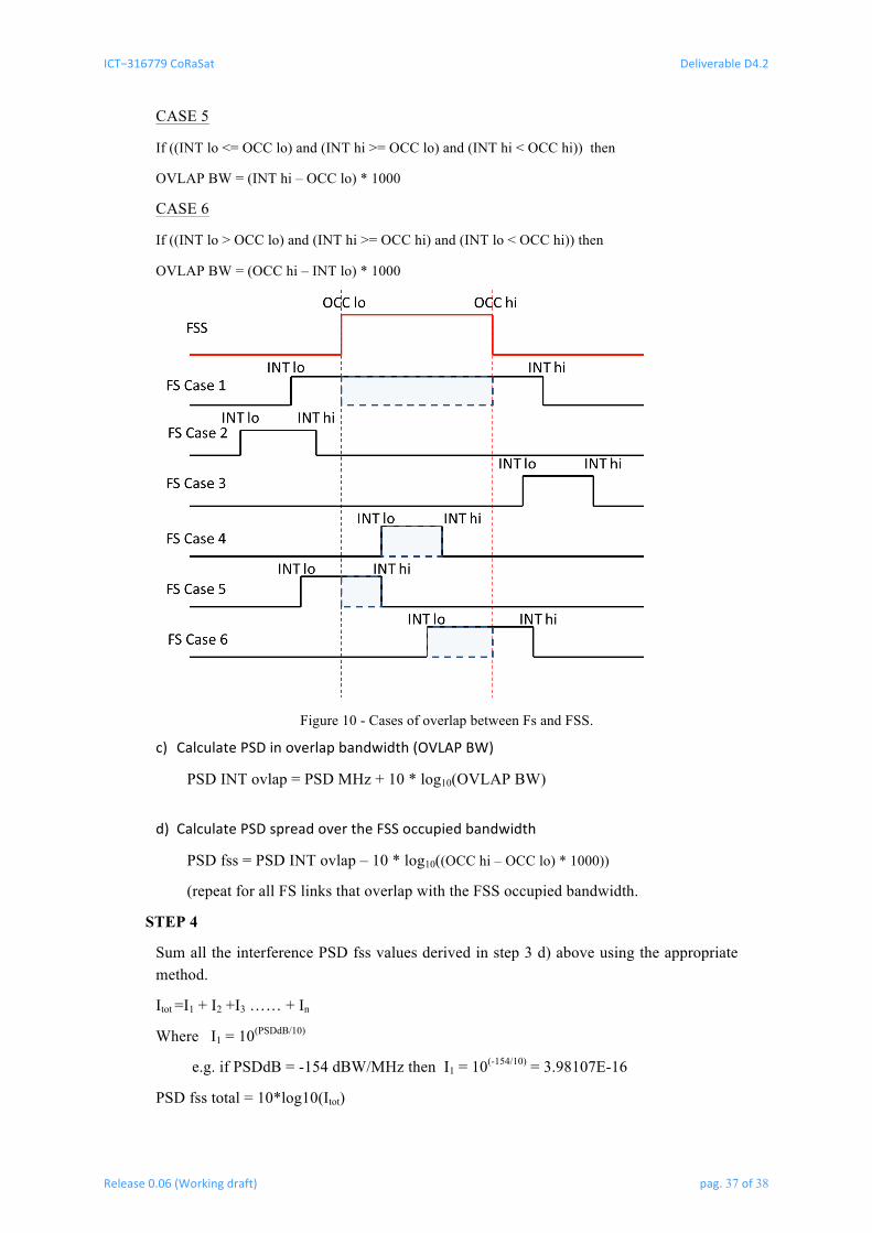
CASE 5
If ((INT lo <= OCC lo) and (INT hi >= OCC lo) and (INT hi < OCC hi)) then
OVLAP BW = (INT hi – OCC lo) * 1000
CASE 6
If ((INT lo > OCC lo) and (INT hi >= OCC hi) and (INT lo < OCC hi)) then
OVLAP BW = (OCC hi – INT lo) * 1000
Figure 10 - Cases of overlap between Fs and FSS.
c) CalculatePSDinoverlapbandwidth(OVLAPBW)
PSD INT ovlap = PSD MHz + 10 * log10(OVLAP BW)
d) CalculatePSDspreadovertheFSSoccupiedbandwidth
PSD fss = PSD INT ovlap – 10 * log10((OCC hi – OCC lo) * 1000))
(repeat for all FS links that overlap with the FSS occupied bandwidth.
STEP 4
Sum all the interference PSD fss values derived in step 3 d) above using the appropriate method.
Itot =I1 + I2 +I3 …… + In
Where I1 = 10(PSDdB/10)
e.g. if PSDdB = -154 dBW/MHz then I1 = 10(-154/10) = 3.98107E-16
PSD fss total = 10*log10(Itot)
ICT−316779CoRaSat DeliverableD4.2
Release0.06(Workingdraft) pag.38of38
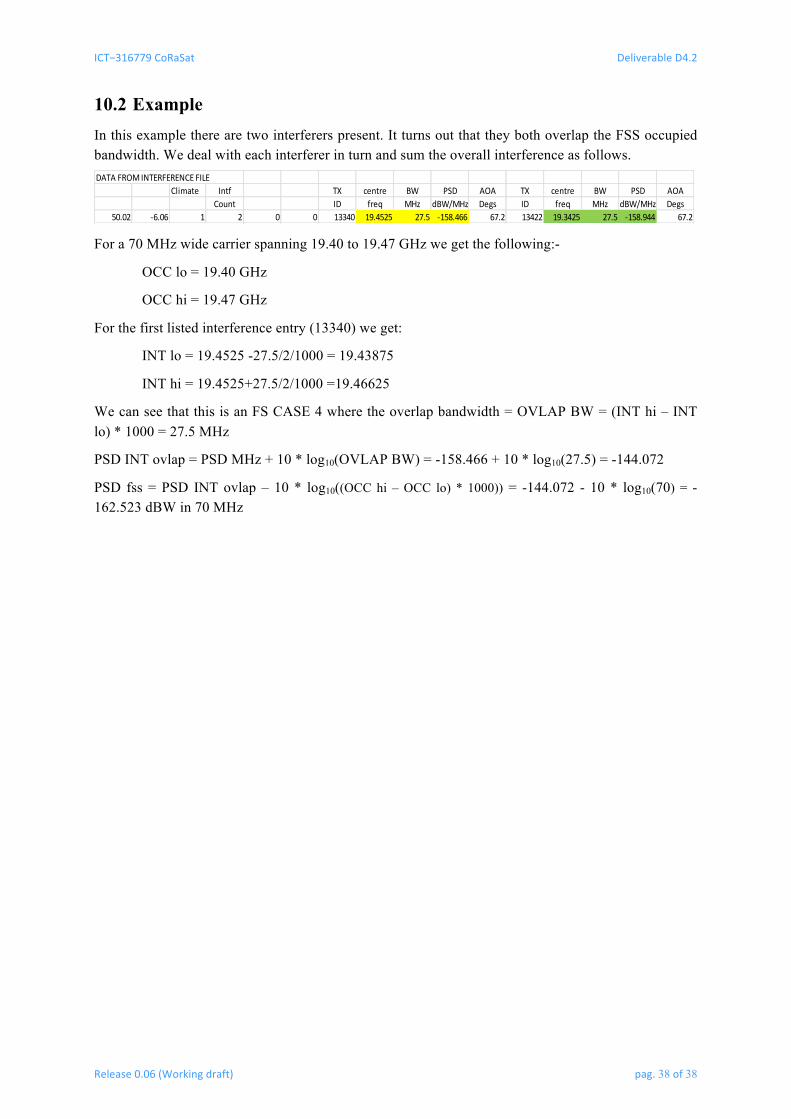
10.2 Example In this example there are two interferers present. It turns out that they both overlap the FSS occupied bandwidth. We deal with each interferer in turn and sum the overall interference as follows. DATAFROMINTERFERENCEFILE
Climate Intf TX centre BW PSD AOA TX centre BW PSD AOACount ID freq MHz dBW/MHz Degs ID freq MHz dBW/MHz Degs
50.02 -6.06 1 2 0 0 13340 19.4525 27.5 -158.466 67.2 13422 19.3425 27.5 -158.944 67.2
For a 70 MHz wide carrier spanning 19.40 to 19.47 GHz we get the following:-
OCC lo = 19.40 GHz
OCC hi = 19.47 GHz
For the first listed interference entry (13340) we get:
INT lo = 19.4525 -27.5/2/1000 = 19.43875
INT hi = 19.4525+27.5/2/1000 =19.46625
We can see that this is an FS CASE 4 where the overlap bandwidth = OVLAP BW = (INT hi – INT lo) * 1000 = 27.5 MHz
PSD INT ovlap = PSD MHz + 10 * log10(OVLAP BW) = -158.466 + 10 * log10(27.5) = -144.072
PSD fss = PSD INT ovlap – 10 * log10((OCC hi – OCC lo) * 1000)) = -144.072 - 10 * log10(70) = -162.523 dBW in 70 MHz