dell emc solutions for microsoft azure stack hci ......2 dell emc solutions for microsoft azure...
TRANSCRIPT
Dell EMC Configuration and Deployment Guide
Dell EMC Solutions for Microsoft Azure Stack HCI Networking Guide
Abstract
This guide provides Microsoft Azure Stack HCI networking deployment
examples using Dell EMC Storage Spaces Direct Ready Nodes and Dell
EMC Networking switches.
May 2019
2 Dell EMC Solutions for Microsoft Azure Stack HCI Networking Guide
Revisions
Date Description
May 2019 Revised Appendix B
March 2019 Initial release
The information in this publication is provided “as is.” Dell Inc. makes no representations or warranties of any kind with respect to the information in this
publication, and specifically disclaims implied warranties of merchantability or fitness for a particular purpose.
Use, copying, and distribution of any software described in this publication requires an applicable software license.
© 2019 Dell Inc. or its subsidiaries. All Rights Reserved. Dell, EMC, Dell EMC and other trademarks are trademarks of Dell Inc. or its subsidiaries. Other
trademarks may be trademarks of their respective owners.
Dell believes the information in this document is accurate as of its publication date. The information is subject to change without notice.
3 Dell EMC Solutions for Microsoft Azure Stack HCI Networking Guide
Table of contents
Revisions............................................................................................................................................................................. 2
1 Introduction ................................................................................................................................................................... 6
1.1 Typographical conventions ................................................................................................................................. 6
1.2 Attachments ........................................................................................................................................................ 6
2 Hardware Overview ...................................................................................................................................................... 7
2.1 Dell EMC Networking S5248F-ON ..................................................................................................................... 7
2.2 Dell EMC Networking S3048-ON ....................................................................................................................... 7
2.3 Dell EMC S2D Ready Nodes .............................................................................................................................. 7
2.4 Management system .......................................................................................................................................... 8
2.5 Supported Dell EMC Networking switches ......................................................................................................... 8
3 Topology ....................................................................................................................................................................... 9
3.1 Connections to leaf switches ............................................................................................................................ 10
3.2 Connections to OOB management switch ....................................................................................................... 11
4 Configuration planning ............................................................................................................................................... 12
4.1 RDMA overview ................................................................................................................................................ 12
4.2 DCB overview ................................................................................................................................................... 12
4.3 Ready Node network adapter options .............................................................................................................. 12
4.3.1 QLogic FastLinQ QL41262 ............................................................................................................................... 12
4.3.2 Mellanox ConnectX-4 Lx .................................................................................................................................. 12
4.4 Adapter/RDMA/DCB options ............................................................................................................................ 13
4.5 VLANs and IP addressing ................................................................................................................................ 13
5 Configure network adapters ....................................................................................................................................... 14
5.1 Reset network adapters to factory defaults ...................................................................................................... 14
5.2 Configure QLogic QL41262 adapters ............................................................................................................... 15
5.3 Verify Mellanox ConnectX-4 Lx adapter settings ............................................................................................. 19
6 Leaf switch configuration prerequisites ...................................................................................................................... 22
6.1 Check switch OS version .................................................................................................................................. 22
6.2 Verify license installation .................................................................................................................................. 22
6.3 Factory default configuration ............................................................................................................................ 23
7 Configure leaf switches .............................................................................................................................................. 24
7.1 General settings................................................................................................................................................ 25
7.2 Configure port-groups ....................................................................................................................................... 25
7.3 Configure VLANs and VRRP ............................................................................................................................ 26
7.4 Configure storage interfaces ............................................................................................................................ 27
7.5 Configure in-band management interfaces ...................................................................................................... 28
4 Dell EMC Solutions for Microsoft Azure Stack HCI Networking Guide
7.6 Configure VLT ................................................................................................................................................... 29
7.7 Configure DCB .................................................................................................................................................. 30
8 Switch validation ......................................................................................................................................................... 33
8.1 General commands .......................................................................................................................................... 33
8.1.1 show interface status ........................................................................................................................................ 33
8.1.2 show vlan .......................................................................................................................................................... 33
8.1.3 show lldp neighbors .......................................................................................................................................... 34
8.1.4 show vrrp brief .................................................................................................................................................. 34
8.2 VLT validation commands ................................................................................................................................ 35
8.2.1 show vlt domain_id ........................................................................................................................................... 35
8.2.2 show vlt domain_id backup-link ........................................................................................................................ 35
8.2.3 show vlt domain_id mismatch ........................................................................................................................... 36
9 S2D Ready Node configuration and deployment ....................................................................................................... 37
9.1 Initial state ......................................................................................................................................................... 37
9.2 Ensure DCB is disabled on Intel X710 adapters .............................................................................................. 38
9.3 Install roles and features .................................................................................................................................. 39
9.4 Configure the in-band management and VM network ...................................................................................... 39
9.5 Configure storage networks .............................................................................................................................. 40
9.5.1 Configure storage VLANs ................................................................................................................................. 40
9.5.2 Configure storage IP addresses ....................................................................................................................... 40
9.5.3 Enable RDMA ................................................................................................................................................... 41
9.5.4 Enable iWARP on QLogic adapters ................................................................................................................. 41
9.5.5 Enable jumbo frames on NICs .......................................................................................................................... 41
9.6 Join Ready Nodes to the Active Directory domain ........................................................................................... 42
9.7 Clean disks ....................................................................................................................................................... 42
9.8 Run the Test-Cluster cmdlet ............................................................................................................................. 44
9.9 Create the cluster ............................................................................................................................................. 44
9.10 Configure a cluster witness .............................................................................................................................. 45
9.11 Enable S2D ....................................................................................................................................................... 46
9.12 Create storage volumes ................................................................................................................................... 46
9.13 Configure DCB on Ready Nodes ...................................................................................................................... 47
10 PowerShell validation commands and output ............................................................................................................ 48
10.1 Get-NetAdapter ................................................................................................................................................. 48
10.2 Get-VMSwitch ................................................................................................................................................... 48
10.3 Get-NetIPAddress ............................................................................................................................................ 49
10.4 Get-NetRoute .................................................................................................................................................... 49
5 Dell EMC Solutions for Microsoft Azure Stack HCI Networking Guide
10.5 Get-DnsClientServerAddress ........................................................................................................................... 49
10.6 View VLAN IDs ................................................................................................................................................. 49
10.7 Get-NetAdapterRdma ....................................................................................................................................... 50
10.8 Ensure iWARP is enabled (QLogic adapters only) ........................................................................................... 50
10.9 View jumbo frame settings ............................................................................................................................... 50
10.10 Storage validation commands .......................................................................................................................... 51
10.10.1 Get-PhysicalDisk ...................................................................................................................................... 51
10.10.2 Get-StoragePool ....................................................................................................................................... 52
10.10.3 Get-VirtualDisk ......................................................................................................................................... 52
10.11 DCB validation commands ............................................................................................................................... 52
10.11.1 Get-NetQosPolicy ..................................................................................................................................... 52
10.11.2 Get-NetAdapterQos .................................................................................................................................. 53
10.11.3 Get-NetQosFlowControl ........................................................................................................................... 54
10.11.4 Get-NetQosTrafficClass ........................................................................................................................... 54
10.11.5 Get-NetQosDcbxSetting ........................................................................................................................... 54
10.11.6 Verify Mellanox adapters are set to “Host in Charge” .............................................................................. 54
11 Switch DCB validation commands ............................................................................................................................. 55
11.1 Show queuing statistics .................................................................................................................................... 55
11.2 Show interface priority flow control ................................................................................................................... 55
A Validated components ................................................................................................................................................ 56
A.1 Dell EMC Networking Switches ........................................................................................................................ 56
A.2 S2D Ready Nodes ............................................................................................................................................ 56
A.3 Management System ........................................................................................................................................ 57
A.4 Dell EMC Networking Optics and Cables ......................................................................................................... 58
A.5 S2D Ready Node and management system software ..................................................................................... 58
B Port-groups ................................................................................................................................................................. 59
C Technical resources ................................................................................................................................................... 61
D Fabric Design Center ................................................................................................................................................. 62
E Support and feedback ................................................................................................................................................ 63
6 Dell EMC Solutions for Microsoft Azure Stack HCI Networking Guide
1 Introduction This guide provides Dell EMC Solutions for Microsoft Azure Stack HCI greenfield network deployment
examples using Dell EMC Storage Spaces Direct Ready Nodes and Dell EMC Networking switches.
S2D is included with Microsoft Windows Server 2019 Datacenter and Windows Server 2016 Datacenter
editions. S2D uses locally attached drives on industry-standard servers to create highly available software-
defined storage.
S2D has two deployment options: converged and hyper-converged. In a converged deployment, storage and
compute resources are in separate clusters which allow for scaling of storage and compute clusters
independently from each other. A hyper-converged deployment uses one cluster for compute and storage.
This allows Hyper-V virtual machines to run directly on the servers providing the storage which can simplify
deployment and reduce hardware costs. This deployment guide uses a hyper-converged S2D deployment.
In an S2D-enabled cluster, storage and non-storage network traffic may share the same physical network
connections (a converged network), or storage traffic may be placed on dedicated physical network
connections (a non-converged network). The examples in this document use a non-converged network.
For more information, see the Dell EMC Solutions for Microsoft Azure Stack HCI Deployment Guide.
1.1 Typographical conventions The CLI and GUI examples in this document use the following conventions:
Monospace Text CLI examples
Underlined Monospace Text CLI examples that wrap the page
Italic Monospace Text Variables in CLI examples
Bold Monospace Text Commands entered at the CLI prompt and highlighted information in CLI
output
Bold text UI elements and information entered in the GUI
1.2 Attachments This document in .pdf format includes one or more file attachments. To access attachments in Adobe Acrobat
Reader, click the icon in the left pane halfway down the page, then click the icon.
7 Dell EMC Solutions for Microsoft Azure Stack HCI Networking Guide
2 Hardware Overview This section briefly describes the hardware used to validate the deployment examples in this document.
Appendix A contains a complete listing of hardware and software validated for this guide.
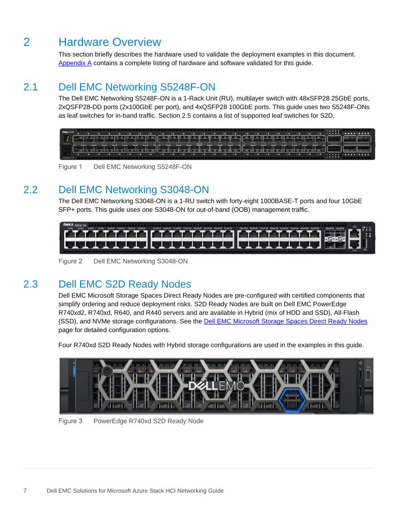
2.1 Dell EMC Networking S5248F-ON The Dell EMC Networking S5248F-ON is a 1-Rack Unit (RU), multilayer switch with 48xSFP28 25GbE ports,
2xQSFP28-DD ports (2x100GbE per port), and 4xQSFP28 100GbE ports. This guide uses two S5248F-ONs
as leaf switches for in-band traffic. Section 2.5 contains a list of supported leaf switches for S2D.
Dell EMC Networking S5248F-ON
2.2 Dell EMC Networking S3048-ON The Dell EMC Networking S3048-ON is a 1-RU switch with forty-eight 1000BASE-T ports and four 10GbE
SFP+ ports. This guide uses one S3048-ON for out-of-band (OOB) management traffic.
Dell EMC Networking S3048-ON
2.3 Dell EMC S2D Ready Nodes Dell EMC Microsoft Storage Spaces Direct Ready Nodes are pre-configured with certified components that
simplify ordering and reduce deployment risks. S2D Ready Nodes are built on Dell EMC PowerEdge
R740xd2, R740xd, R640, and R440 servers and are available in Hybrid (mix of HDD and SSD), All-Flash
(SSD), and NVMe storage configurations. See the Dell EMC Microsoft Storage Spaces Direct Ready Nodes
page for detailed configuration options.
Four R740xd S2D Ready Nodes with Hybrid storage configurations are used in the examples in this guide.
PowerEdge R740xd S2D Ready Node
8 Dell EMC Solutions for Microsoft Azure Stack HCI Networking Guide
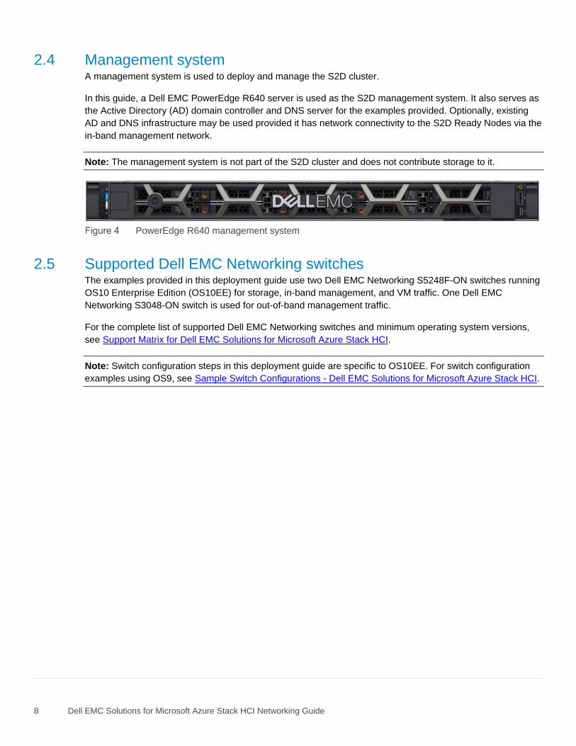
2.4 Management system A management system is used to deploy and manage the S2D cluster.
In this guide, a Dell EMC PowerEdge R640 server is used as the S2D management system. It also serves as
the Active Directory (AD) domain controller and DNS server for the examples provided. Optionally, existing
AD and DNS infrastructure may be used provided it has network connectivity to the S2D Ready Nodes via the
in-band management network.
Note: The management system is not part of the S2D cluster and does not contribute storage to it.
PowerEdge R640 management system
2.5 Supported Dell EMC Networking switches The examples provided in this deployment guide use two Dell EMC Networking S5248F-ON switches running
OS10 Enterprise Edition (OS10EE) for storage, in-band management, and VM traffic. One Dell EMC
Networking S3048-ON switch is used for out-of-band management traffic.
For the complete list of supported Dell EMC Networking switches and minimum operating system versions,
see Support Matrix for Dell EMC Solutions for Microsoft Azure Stack HCI.
Note: Switch configuration steps in this deployment guide are specific to OS10EE. For switch configuration
examples using OS9, see Sample Switch Configurations - Dell EMC Solutions for Microsoft Azure Stack HCI.
9 Dell EMC Solutions for Microsoft Azure Stack HCI Networking Guide
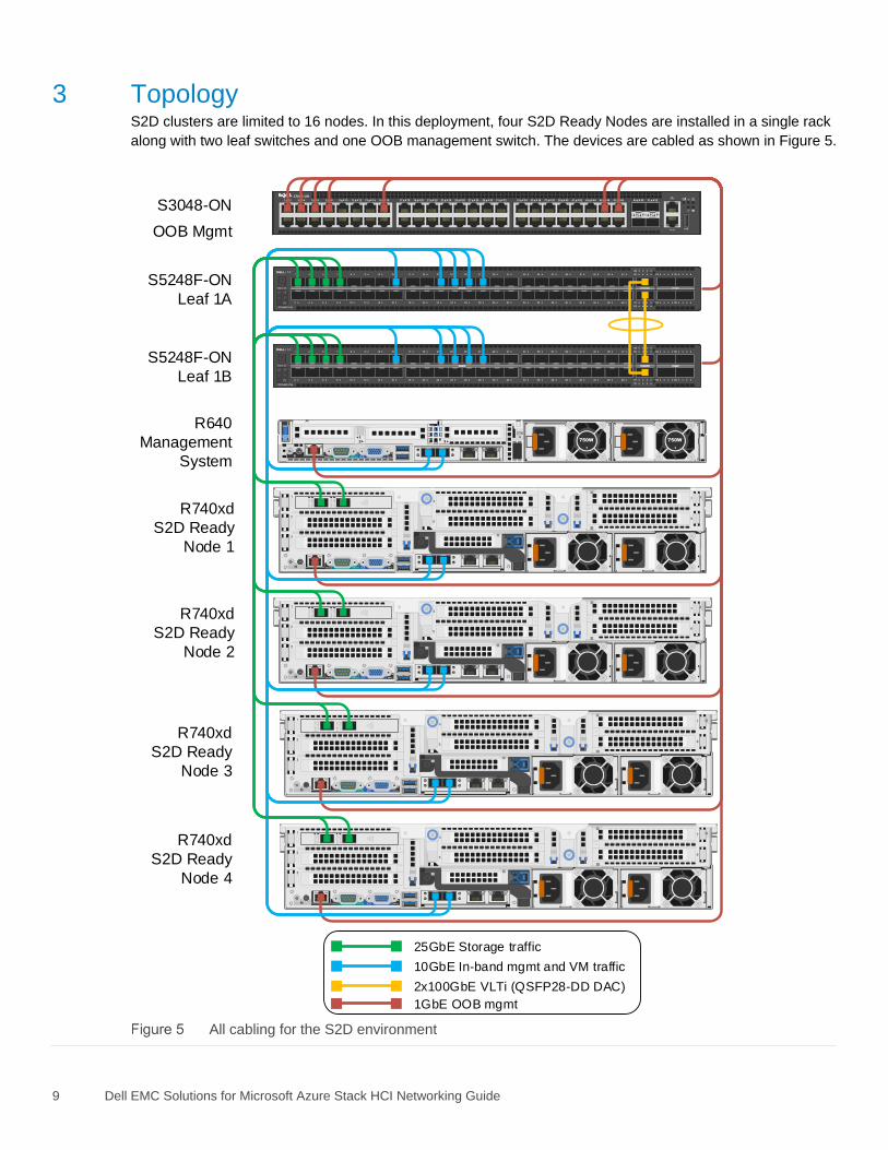
3 Topology S2D clusters are limited to 16 nodes. In this deployment, four S2D Ready Nodes are installed in a single rack
along with two leaf switches and one OOB management switch. The devices are cabled as shown in Figure 5.
GR
N=10G
ACT/LN
K A
GR
N=10G
ACT/LN
K B
GR
N=10G
ACT/LN
K A
GR
N=10G
ACT/LN
K B
GR
N=10G
ACT/LN
K A
GR
N=10G
ACT/LN
K B
GR
N=10G
ACT/LN
K A
GR
N=10G
ACT/LN
K B
Stack ID
Stack ID
17 18 19 20 21 22 23 24 25 26 27 28 29 30 31 321 2 3 4 5 6 7 8 9 10 11 12 13 14 15 16 33 34 35 36 37 38 39 40 41 42 43 44 45 46 47 48 51 5249 50
S3048-ON
OOB Mgmt
R740xd
S2D Ready
Node 2
R740xd
S2D Ready
Node 3
R740xd
S2D Ready
Node 4
112 750W 750W3
iDRAC
R640
Management
System
25GbE Storage traffic
10GbE In-band mgmt and VM traffic
2x100GbE VLTi (QSFP28-DD DAC)
1GbE OOB mgmt
R740xd
S2D Ready
Node 1
S5248F-ON
Leaf 1B
S5248F-ON
Leaf 1A
All cabling for the S2D environment
10 Dell EMC Solutions for Microsoft Azure Stack HCI Networking Guide
The two leaf switches are connected to spine switches upstream (not shown). Using two leaf switches
provides fault tolerance and twice the bandwidth.
Note: Spine switch configuration is beyond the scope of this guide and is covered in Dell EMC Networking
Layer 3 Leaf-Spine Deployment and Best Practices with OS10EE.
3.1 Connections to leaf switches Each S5248F-ON switch has 48x25GbE ports available for connections to S2D Ready Nodes and other
servers in the rack. Connections from the Ready Nodes to the leaf switches are used for S2D storage traffic,
in-band host management traffic, and VM traffic. All traffic may share the same physical connections
(converged network), or storage traffic may be placed on dedicated network connections (non-converged
network).
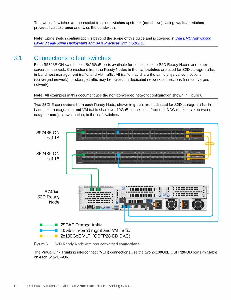
Note: All examples in this document use the non-converged network configuration shown in Figure 6.
Two 25GbE connections from each Ready Node, shown in green, are dedicated for S2D storage traffic. In-
band host management and VM traffic share two 10GbE connections from the rNDC (rack server network
daughter card), shown in blue, to the leaf switches.
Stack ID
Stack ID
GRN
=10G
ACT/LN
K A
GRN
=10G
ACT/LN
K B
25GbE Storage traffic
10GbE In-band mgmt and VM traffic
2x100GbE VLTi (QSFP28-DD DAC)
S5248F-ON
Leaf 1A
S5248F-ON
Leaf 1B
R740xd
S2D Ready
Node
S2D Ready Node with non-converged connections
The Virtual Link Trunking interconnect (VLTi) connections use the two 2x100GbE QSFP28-DD ports available
on each S5248F-ON.
11 Dell EMC Solutions for Microsoft Azure Stack HCI Networking Guide
3.2 Connections to OOB management switch The OOB management network is an isolated network for remote management of servers, switches, and
other devices. It is also used to carry heartbeat messages sent between leaf switches configured as VLT
peers.
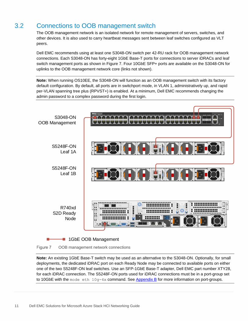
Dell EMC recommends using at least one S3048-ON switch per 42-RU rack for OOB management network
connections. Each S3048-ON has forty-eight 1GbE Base-T ports for connections to server iDRACs and leaf
switch management ports as shown in Figure 7. Four 10GbE SFP+ ports are available on the S3048-ON for
uplinks to the OOB management network core (links not shown).
Note: When running OS10EE, the S3048-ON will function as an OOB management switch with its factory
default configuration. By default, all ports are in switchport mode, in VLAN 1, administratively up, and rapid
per-VLAN spanning tree plus (RPVST+) is enabled. At a minimum, Dell EMC recommends changing the
admin password to a complex password during the first login.
17 18 19 20 21 22 23 24 25 26 27 28 29 30 31 321 2 3 4 5 6 7 8 9 10 11 12 13 14 15 16 33 34 35 36 37 38 39 40 41 42 43 44 45 46 47 48 51 5249 50
GR
N=10G
ACT/LN
K A
GR
N=10G
ACT/LN
K B
1GbE OOB Management
S5248F-ON
Leaf 1A
S5248F-ON
Leaf 1B
R740xd
S2D Ready
Node
S3048-ON
OOB Management
OOB management network connections
Note: An existing 1GbE Base-T switch may be used as an alternative to the S3048-ON. Optionally, for small
deployments, the dedicated iDRAC port on each Ready Node may be connected to available ports on either
one of the two S5248F-ON leaf switches. Use an SFP-1GbE Base-T adapter, Dell EMC part number XTY28,
for each iDRAC connection. The S5248F-ON ports used for iDRAC connections must be in a port-group set
to 10GbE with the mode eth 10g-4x command. See Appendix B for more information on port-groups.
12 Dell EMC Solutions for Microsoft Azure Stack HCI Networking Guide
4 Configuration planning The network adapters installed in the Ready Nodes determine which Remote Direct Memory Access (RDMA)
options are available and whether Data Center Bridging (DCB) is required or not.
4.1 RDMA overview S2D Ready Nodes use network adapters that are RDMA capable. RDMA significantly increases throughput
and lowers latency by performing direct memory transfers between servers.
There are two implementations of RDMA supported with S2D Ready Nodes:
1. RDMA over Converged Ethernet (RoCE). RoCE is defined by the InfiniBand Trade Association
(IBTA). S2D Ready Nodes with Mellanox ConnectX-4 Lx adapters use RoCEv2. RoCEv2 uses
UDP/IP as its transport protocol.
2. Internet Wide-area RDMA Protocol (iWARP). iWARP is defined by the Internet Engineering Task
Force (IETF) and uses TCP/IP as its transport protocol.
4.2 DCB overview DCB provides enhancements to Ethernet communication with Priority Flow Control (PFC) and Enhanced
Transmission Selection (ETS). Priority flow control is used to prevent frame loss due to buffer overflows for
selected traffic classes such as storage traffic. ETS is used to guarantee a minimum percentage of bandwidth
for selected traffic classes. For example, 60% of available bandwidth may be reserved for storage traffic with
the remaining 40% reserved for all other traffic.
Note: With ETS, 100% of the bandwidth is available for all traffic unless there is contention between traffic
classes.
DCB is not required for this deployment. However, Dell EMC recommends using DCB if NVMe drives are in
use on the Ready Nodes.
4.3 Ready Node network adapter options
4.3.1 QLogic FastLinQ QL41262 The QLogic FastLinQ QL41262 is a dual port 25GbE network adapter that supports both iWARP and RoCE.
Note: Dell EMC S2D Ready Nodes with QLogic FastLinQ QL41262 adapters are only validated with iWARP.
Ready Nodes with Mellanox ConnectX-4 Lx adapters are validated with RoCEv2.
If QLogic QL41262 adapters with iWARP enabled are used, DCB is not required. However, Dell EMC
recommends using DCB if NVMe drives are in use.
4.3.2 Mellanox ConnectX-4 Lx The Mellanox ConnectX-4 Lx is a dual port 25GbE network adapter that supports RoCEv2.
If Mellanox ConnectX-4 adapters are used, DCB is not required. However, Dell EMC recommends using DCB
if NVMe drives are in use.
13 Dell EMC Solutions for Microsoft Azure Stack HCI Networking Guide
4.4 Adapter/RDMA/DCB options This guide is applicable to the following network adapter, RDMA, and DCB combinations:
• QLogic QL41262 – iWARP with or without DCB
• Mellanox ConnectX-4 Lx – RoCEv2 with or without DCB
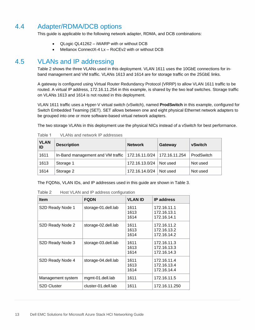
4.5 VLANs and IP addressing Table 2 shows the three VLANs used in this deployment. VLAN 1611 uses the 10GbE connections for in-
band management and VM traffic. VLANs 1613 and 1614 are for storage traffic on the 25GbE links.
A gateway is configured using Virtual Router Redundancy Protocol (VRRP) to allow VLAN 1611 traffic to be
routed. A virtual IP address, 172.16.11.254 in this example, is shared by the two leaf switches. Storage traffic
on VLANs 1613 and 1614 is not routed in this deployment.
VLAN 1611 traffic uses a Hyper-V virtual switch (vSwitch), named ProdSwitch in this example, configured for
Switch Embedded Teaming (SET). SET allows between one and eight physical Ethernet network adapters to
be grouped into one or more software-based virtual network adapters.
The two storage VLANs in this deployment use the physical NICs instead of a vSwitch for best performance.
VLANs and network IP addresses
VLAN ID
Description Network Gateway vSwitch
1611 In-Band management and VM traffic 172.16.11.0/24 172.16.11.254 ProdSwitch
1613 Storage 1 172.16.13.0/24 Not used Not used
1614 Storage 2 172.16.14.0/24 Not used Not used
The FQDNs, VLAN IDs, and IP addresses used in this guide are shown in Table 3.
Host VLAN and IP address configuration
Item FQDN VLAN ID IP address
S2D Ready Node 1 storage-01.dell.lab 1611 1613 1614
172.16.11.1 172.16.13.1 172.16.14.1
S2D Ready Node 2 storage-02.dell.lab 1611 1613 1614
172.16.11.2 172.16.13.2 172.16.14.2
S2D Ready Node 3 storage-03.dell.lab 1611 1613 1614
172.16.11.3 172.16.13.3 172.16.14.3
S2D Ready Node 4 storage-04.dell.lab 1611 1613 1614
172.16.11.4 172.16.13.4 172.16.14.4
Management system mgmt-01.dell.lab 1611 172.16.11.5
S2D Cluster cluster-01.dell.lab 1611 172.16.11.250

14 Dell EMC Solutions for Microsoft Azure Stack HCI Networking Guide
5 Configure network adapters
Note: Exact iDRAC steps in this section may vary depending on hardware, software and browser versions
used. See the PowerEdge server documentation for steps to connect to the iDRAC.
5.1 Reset network adapters to factory defaults
Note: These steps are only necessary for network adapters that have been modified from their factory default
settings.
1. Connect to the server's iDRAC in a web browser and launch the virtual console.
2. In the virtual console, from the Next Boot menu, select BIOS Setup.
3. Reboot the server.
4. On the System Setup Main Menu page, select Device Settings.
Device Settings menu item
5. On the Device Settings page, click the first network adapter port in the list to launch the Main
Configuration Page for the port.
First NIC port in the device list
15 Dell EMC Solutions for Microsoft Azure Stack HCI Networking Guide
6. On the Main Configuration Page for the port, click the Default button followed by Yes to load the
default settings. Click OK to acknowledge the Success message.
7. Click Finish. Notice if the message indicates a reboot is required for changes to take effect.
8. Click Yes to save changes. Click OK to acknowledge the Success message.
9. Repeat steps 5-8 for each network adapter port listed on the Device Settings page.
10. If a reboot is required per step 7, exit System Setup to reboot the system and press F2 when
prompted to return to System Setup to configure the QLogic QL41262 per Section 5.2 or Mellanox
ConnectX-4 Lx per Section 5.3.
Note: Intel X710/i350 and Mellanox ConnectX-4 Lx adapters use their default System Setup configuration for
this deployment.
5.2 Configure QLogic QL41262 adapters This section configures the QL41262 adapters for iWARP with or without DCB. If Mellanox ConnectX-4 Lx
adapters are used, skip to Section 5.3.
If the system is already in System Setup from the prior section, skip to step 4.
1. Connect to the server's iDRAC in a web browser and launch the virtual console.
2. In the virtual console, from the Next Boot menu, select BIOS Setup.
3. Reboot the server.
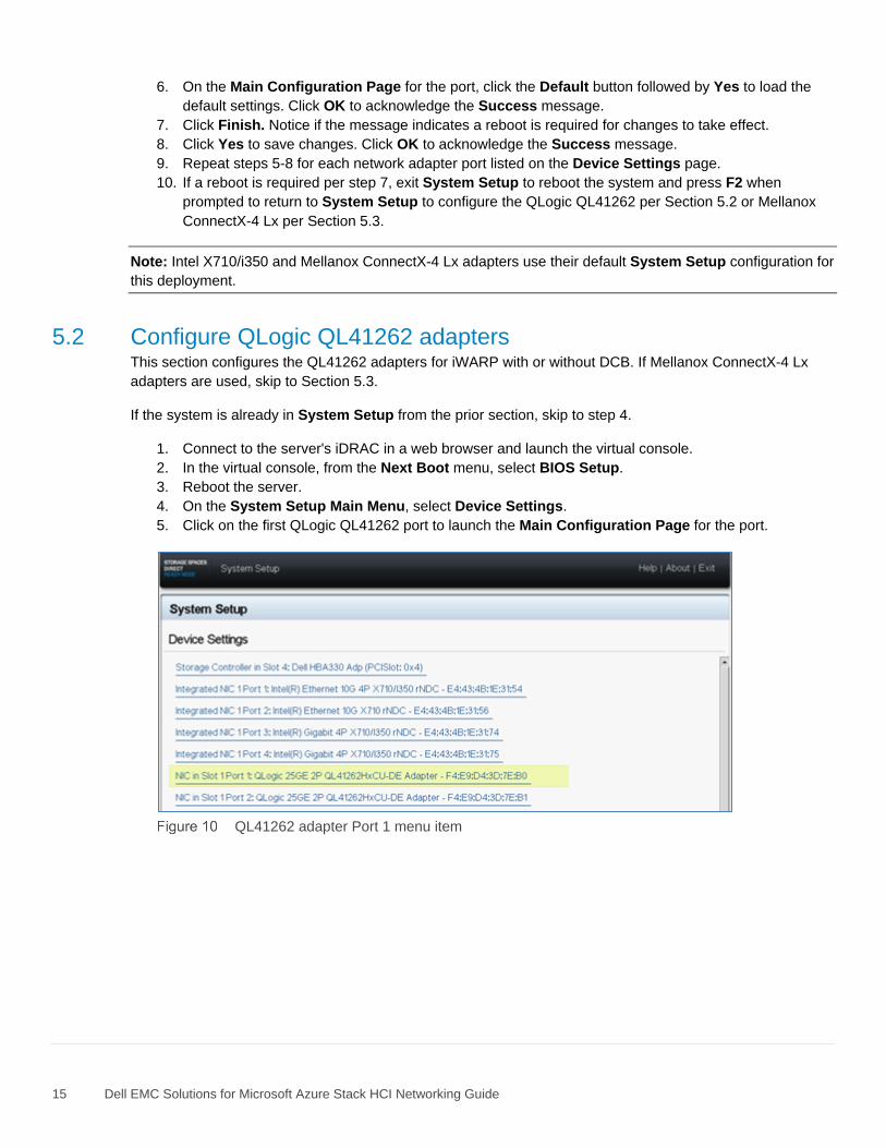
4. On the System Setup Main Menu, select Device Settings.
5. Click on the first QLogic QL41262 port to launch the Main Configuration Page for the port.
QL41262 adapter Port 1 menu item
16 Dell EMC Solutions for Microsoft Azure Stack HCI Networking Guide
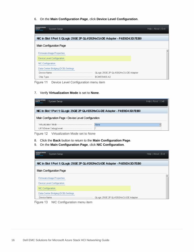
6. On the Main Configuration Page, click Device Level Configuration.
Device Level Configuration menu item
7. Verify Virtualization Mode is set to None.
Virtualization Mode set to None
8. Click the Back button to return to the Main Configuration Page.
9. On the Main Configuration Page, click NIC Configuration.
NIC Configuration menu item
17 Dell EMC Solutions for Microsoft Azure Stack HCI Networking Guide
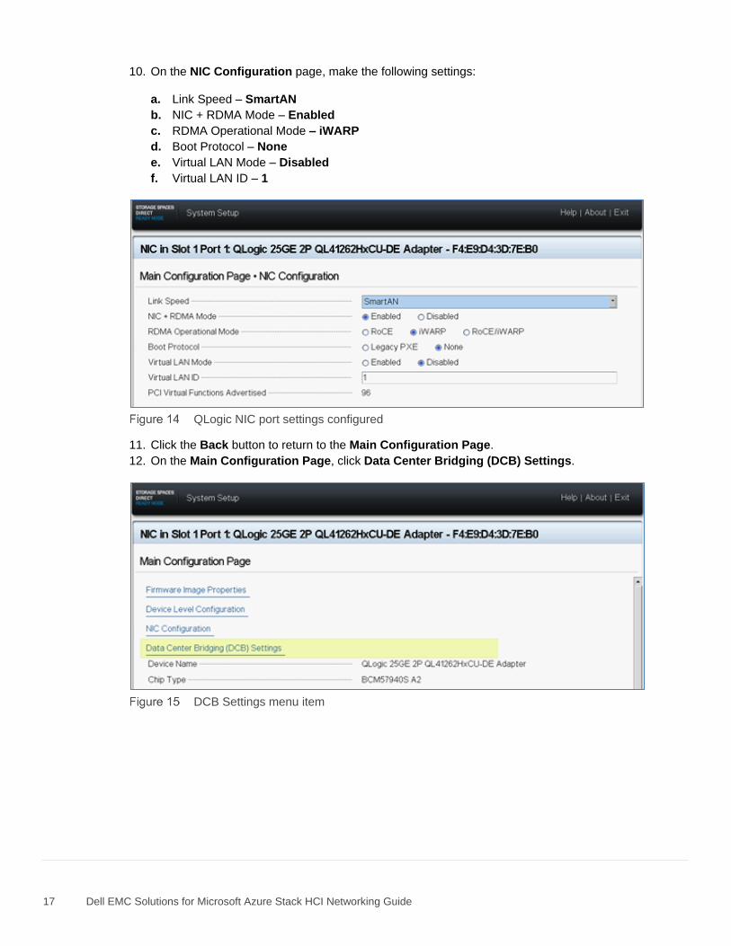
10. On the NIC Configuration page, make the following settings:
a. Link Speed – SmartAN
b. NIC + RDMA Mode – Enabled
c. RDMA Operational Mode – iWARP
d. Boot Protocol – None
e. Virtual LAN Mode – Disabled
f. Virtual LAN ID – 1
QLogic NIC port settings configured
11. Click the Back button to return to the Main Configuration Page.
12. On the Main Configuration Page, click Data Center Bridging (DCB) Settings.
DCB Settings menu item
18 Dell EMC Solutions for Microsoft Azure Stack HCI Networking Guide
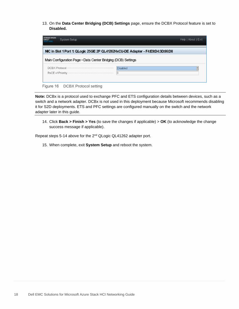
13. On the Data Center Bridging (DCB) Settings page, ensure the DCBX Protocol feature is set to
Disabled.
DCBX Protocol setting
Note: DCBx is a protocol used to exchange PFC and ETS configuration details between devices, such as a
switch and a network adapter. DCBx is not used in this deployment because Microsoft recommends disabling
it for S2D deployments. ETS and PFC settings are configured manually on the switch and the network
adapter later in this guide.
14. Click Back > Finish > Yes (to save the changes if applicable) > OK (to acknowledge the change
success message if applicable).
Repeat steps 5-14 above for the 2nd QLogic QL41262 adapter port.
15. When complete, exit System Setup and reboot the system.
19 Dell EMC Solutions for Microsoft Azure Stack HCI Networking Guide
5.3 Verify Mellanox ConnectX-4 Lx adapter settings This section verifies the Mellanox ConnectX-4 Lx adapters are configured properly.
Note: The settings shown in this section are factory defaults. This section may be skipped if the Mellanox
ConnectX-4 Lx adapters are known to be at their factory default settings. There are no RDMA or DCB settings
in System Setup for this adapter.
If the system is already in System Setup from Section 5.1, skip to step 4.
1. Connect to the server's iDRAC in a web browser and launch the virtual console.
2. In the virtual console, from the Next Boot menu, select BIOS Setup.
3. Reboot the server.
4. On the System Setup Main Menu page, select Device Settings.
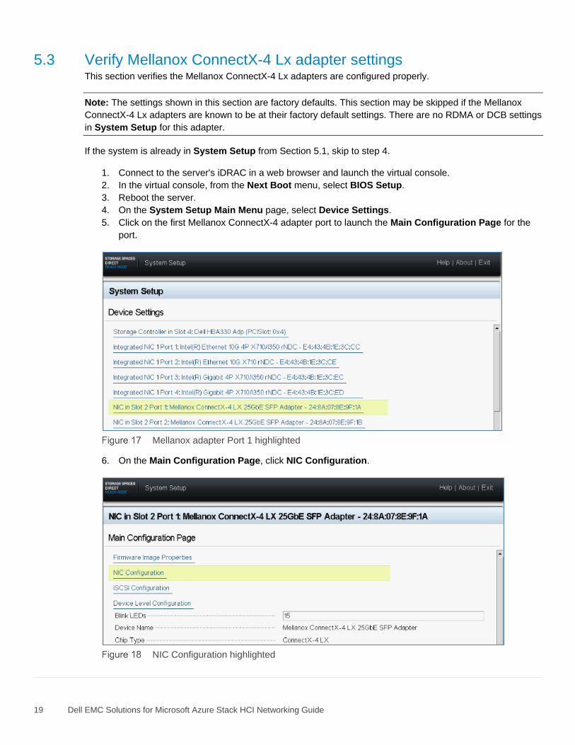
5. Click on the first Mellanox ConnectX-4 adapter port to launch the Main Configuration Page for the
port.
Mellanox adapter Port 1 highlighted
6. On the Main Configuration Page, click NIC Configuration.
NIC Configuration highlighted
20 Dell EMC Solutions for Microsoft Azure Stack HCI Networking Guide
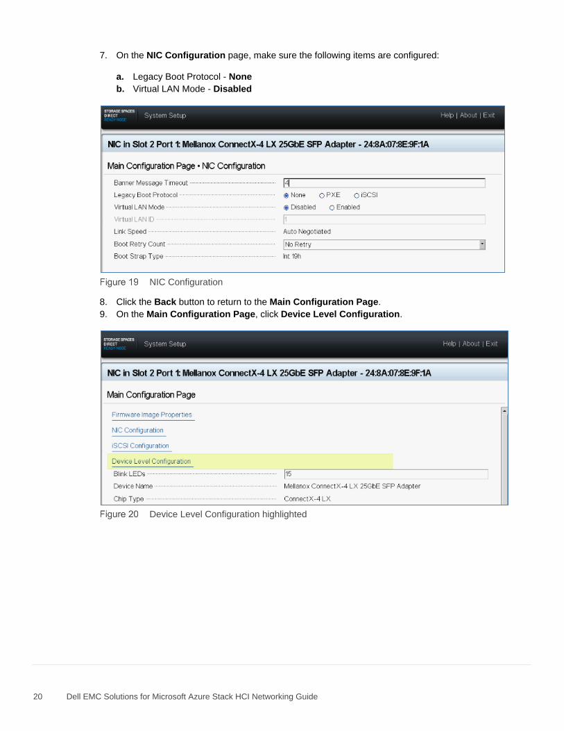
7. On the NIC Configuration page, make sure the following items are configured:
a. Legacy Boot Protocol - None
b. Virtual LAN Mode - Disabled
NIC Configuration
8. Click the Back button to return to the Main Configuration Page.
9. On the Main Configuration Page, click Device Level Configuration.
Device Level Configuration highlighted
21 Dell EMC Solutions for Microsoft Azure Stack HCI Networking Guide
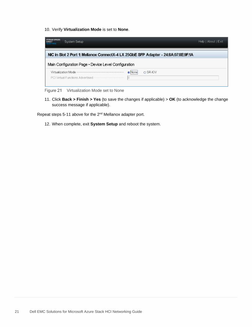
10. Verify Virtualization Mode is set to None.
Virtualization Mode set to None
11. Click Back > Finish > Yes (to save the changes if applicable) > OK (to acknowledge the change
success message if applicable).
Repeat steps 5-11 above for the 2nd Mellanox adapter port.
12. When complete, exit System Setup and reboot the system.
22 Dell EMC Solutions for Microsoft Azure Stack HCI Networking Guide
6 Leaf switch configuration prerequisites
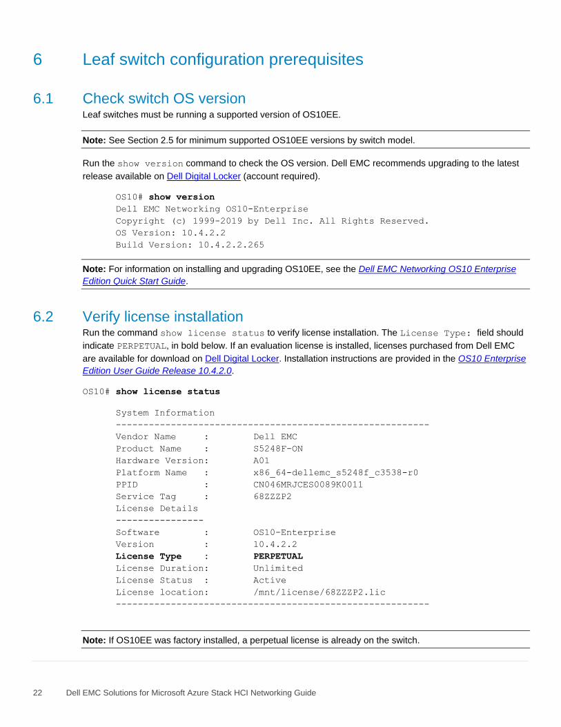
6.1 Check switch OS version Leaf switches must be running a supported version of OS10EE.
Note: See Section 2.5 for minimum supported OS10EE versions by switch model.
Run the show version command to check the OS version. Dell EMC recommends upgrading to the latest
release available on Dell Digital Locker (account required).
OS10# show version
Dell EMC Networking OS10-Enterprise
Copyright (c) 1999-2019 by Dell Inc. All Rights Reserved.
OS Version: 10.4.2.2
Build Version: 10.4.2.2.265
Note: For information on installing and upgrading OS10EE, see the Dell EMC Networking OS10 Enterprise
Edition Quick Start Guide.
6.2 Verify license installation Run the command show license status to verify license installation. The License Type: field should
indicate PERPETUAL, in bold below. If an evaluation license is installed, licenses purchased from Dell EMC
are available for download on Dell Digital Locker. Installation instructions are provided in the OS10 Enterprise
Edition User Guide Release 10.4.2.0.
OS10# show license status
System Information
---------------------------------------------------------
Vendor Name : Dell EMC
Product Name : S5248F-ON
Hardware Version: A01
Platform Name : x86_64-dellemc_s5248f_c3538-r0
PPID : CN046MRJCES0089K0011
Service Tag : 68ZZZP2
License Details
----------------
Software : OS10-Enterprise
Version : 10.4.2.2
License Type : PERPETUAL
License Duration: Unlimited
License Status : Active
License location: /mnt/license/68ZZZP2.lic
---------------------------------------------------------
Note: If OS10EE was factory installed, a perpetual license is already on the switch.
23 Dell EMC Solutions for Microsoft Azure Stack HCI Networking Guide
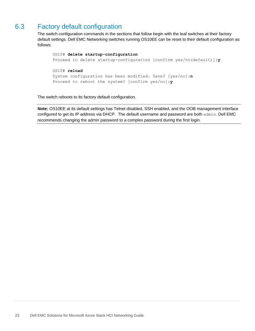
6.3 Factory default configuration The switch configuration commands in the sections that follow begin with the leaf switches at their factory
default settings. Dell EMC Networking switches running OS10EE can be reset to their default configuration as
follows:
OS10# delete startup-configuration
Proceed to delete startup-configuration [confirm yes/no(default)]:y
OS10# reload
System configuration has been modified. Save? [yes/no]:n
Proceed to reboot the system? [confirm yes/no]:y
The switch reboots to its factory default configuration.
Note: OS10EE at its default settings has Telnet disabled, SSH enabled, and the OOB management interface
configured to get its IP address via DHCP. The default username and password are both admin. Dell EMC
recommends changing the admin password to a complex password during the first login.
24 Dell EMC Solutions for Microsoft Azure Stack HCI Networking Guide
7 Configure leaf switches This chapter details the configuration commands issued to the S5248F-ON leaf switches. The switches start
at their factory default settings per Section 6.3. The commands in the sections that follow should be entered in
the order shown.
Note: S5248F-Leaf1A and S5248F-Leaf1B switch running-configuration files, with and without DCB, are
provided as text file attachments to this .pdf. Section 1.2 describes how to access .pdf attachments.
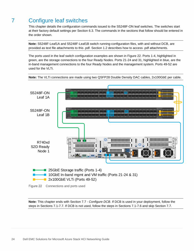
The ports used in the leaf switch configuration examples are shown in Figure 22. Ports 1-4, highlighted in
green, are the storage connections to the four Ready Nodes. Ports 21-24 and 31, highlighted in blue, are the
in-band management connections to the four Ready Nodes and the management system. Ports 49-52 are
used for the VLTi.
Note: The VLTi connections are made using two QSFP28 Double Density DAC cables, 2x100GbE per cable.
Stack ID
Stack ID
GRN
=10G
ACT/LN
K A
GRN
=10G
ACT/LN
K B
25GbE Storage traffic (Ports 1-4)
10GbE In-band mgmt and VM traffic (Ports 21-24 & 31)
2x100GbE VLTi (Ports 49-52)
S5248F-ON
Leaf 1A
S5248F-ON
Leaf 1B
R740xd
S2D Ready
Node 1
Connections and ports used
Note: This chapter ends with Section 7.7 - Configure DCB. If DCB is used in your deployment, follow the
steps in Sections 7.1-7.7. If DCB is not used, follow the steps in Sections 7.1-7.6 and skip Section 7.7.
25 Dell EMC Solutions for Microsoft Azure Stack HCI Networking Guide
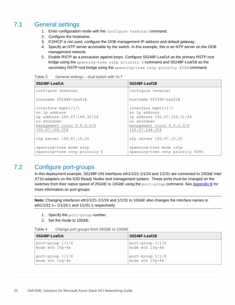
7.1 General settings 1. Enter configuration mode with the configure terminal command.
2. Configure the hostname.
3. If DHCP is not used, configure the OOB management IP address and default gateway.
4. Specify an NTP server accessible by the switch. In this example, this is an NTP server on the OOB
management network.
5. Enable RSTP as a precaution against loops. Configure S5248F-Leaf1A as the primary RSTP root
bridge using the spanning-tree rstp priority 0 command and S5248F-Leaf1B as the
secondary RSTP root bridge using the spanning-tree rstp priority 4096 command.
General settings – dual switch with VLT
S5248F-Leaf1A S5248F-Leaf1B
configure terminal
hostname S5248F-Leaf1A
interface mgmt1/1/1
no ip address
ip address 100.67.168.32/24
no shutdown
management route 0.0.0.0/0
100.67.168.254
ntp server 100.67.10.20
spanning-tree mode rstp
spanning-tree rstp priority 0
configure terminal
hostname S5248F-Leaf1B
interface mgmt1/1/1
no ip address
ip address 100.67.168.31/24
no shutdown
management route 0.0.0.0/0
100.67.168.254
ntp server 100.67.10.20
spanning-tree mode rstp
spanning-tree rstp priority 4096
7.2 Configure port-groups In this deployment example, S5248F-ON interfaces eth1/1/21-1/1/24 and 1/1/31 are connected to 10GbE Intel
X710 adapters on the S2D Ready Nodes and management system. These ports must be changed on the
switches from their native speed of 25GbE to 10GbE using the port-group command. See Appendix B for
more information on port-groups.
Note: Changing interfaces eth1/1/21-1/1/24 and 1/1/31 to 10GbE also changes the interface names to
eth1/1/21:1– 1/1/24:1 and 1/1/31:1 respectively.
1. Specify the port-group number.
2. Set the mode to 10GbE.
Change port groups from 25GbE to 10GbE
S5248F-Leaf1A S5248F-Leaf1B
port-group 1/1/6
mode eth 10g-4x
port-group 1/1/8
mode eth 10g-4x
port-group 1/1/6
mode eth 10g-4x
port-group 1/1/8
mode eth 10g-4x
26 Dell EMC Solutions for Microsoft Azure Stack HCI Networking Guide
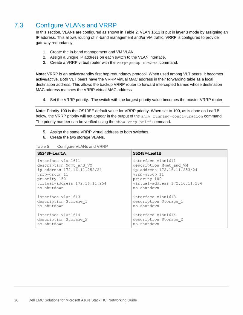
7.3 Configure VLANs and VRRP In this section, VLANs are configured as shown in Table 2. VLAN 1611 is put in layer 3 mode by assigning an
IP address. This allows routing of in-band management and/or VM traffic. VRRP is configured to provide
gateway redundancy.
1. Create the in-band management and VM VLAN.
2. Assign a unique IP address on each switch to the VLAN interface.
3. Create a VRRP virtual router with the vrrp-group number command.
Note: VRRP is an active/standby first hop redundancy protocol. When used among VLT peers, it becomes
active/active. Both VLT peers have the VRRP virtual MAC address in their forwarding table as a local
destination address. This allows the backup VRRP router to forward intercepted frames whose destination
MAC address matches the VRRP virtual MAC address.
4. Set the VRRP priority. The switch with the largest priority value becomes the master VRRP router.
Note: Priority 100 is the OS10EE default value for VRRP priority. When set to 100, as is done on Leaf1B
below, the VRRP priority will not appear in the output of the show running-configuration command.
The priority number can be verified using the show vrrp brief command.
5. Assign the same VRRP virtual address to both switches.
6. Create the two storage VLANs.
Configure VLANs and VRRP
S5248F-Leaf1A S5248F-Leaf1B
interface vlan1611
description Mgmt_and_VM
ip address 172.16.11.252/24
vrrp-group 11
priority 150
virtual-address 172.16.11.254
no shutdown
interface vlan1613
description Storage_1
no shutdown
interface vlan1614
description Storage_2
no shutdown
interface vlan1611
description Mgmt_and_VM
ip address 172.16.11.253/24
vrrp-group 11
priority 100
virtual-address 172.16.11.254
no shutdown
interface vlan1613
description Storage_1
no shutdown
interface vlan1614
description Storage_2
no shutdown
27 Dell EMC Solutions for Microsoft Azure Stack HCI Networking Guide
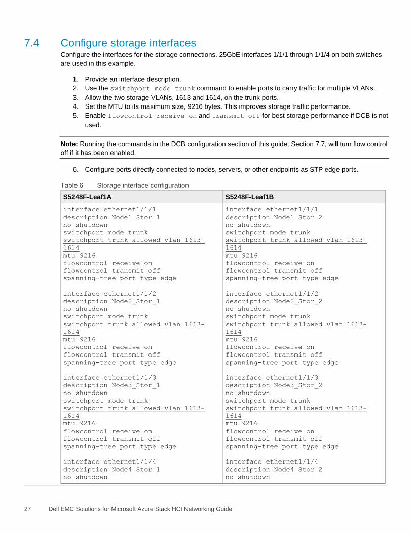
7.4 Configure storage interfaces Configure the interfaces for the storage connections. 25GbE interfaces 1/1/1 through 1/1/4 on both switches
are used in this example.
1. Provide an interface description.
2. Use the switchport mode trunk command to enable ports to carry traffic for multiple VLANs.
3. Allow the two storage VLANs, 1613 and 1614, on the trunk ports.
4. Set the MTU to its maximum size, 9216 bytes. This improves storage traffic performance.
5. Enable flowcontrol receive on and transmit off for best storage performance if DCB is not
used.
Note: Running the commands in the DCB configuration section of this guide, Section 7.7, will turn flow control
off if it has been enabled.
6. Configure ports directly connected to nodes, servers, or other endpoints as STP edge ports.
Storage interface configuration
S5248F-Leaf1A S5248F-Leaf1B
interface ethernet1/1/1
description Node1_Stor_1
no shutdown
switchport mode trunk
switchport trunk allowed vlan 1613-
1614
mtu 9216
flowcontrol receive on
flowcontrol transmit off
spanning-tree port type edge
interface ethernet1/1/2
description Node2_Stor_1
no shutdown
switchport mode trunk
switchport trunk allowed vlan 1613-
1614
mtu 9216
flowcontrol receive on
flowcontrol transmit off
spanning-tree port type edge
interface ethernet1/1/3
description Node3_Stor_1
no shutdown
switchport mode trunk
switchport trunk allowed vlan 1613-
1614
mtu 9216
flowcontrol receive on
flowcontrol transmit off
spanning-tree port type edge
interface ethernet1/1/4
description Node4_Stor_1
no shutdown
interface ethernet1/1/1
description Node1_Stor_2
no shutdown
switchport mode trunk
switchport trunk allowed vlan 1613-
1614
mtu 9216
flowcontrol receive on
flowcontrol transmit off
spanning-tree port type edge
interface ethernet1/1/2
description Node2_Stor_2
no shutdown
switchport mode trunk
switchport trunk allowed vlan 1613-
1614
mtu 9216
flowcontrol receive on
flowcontrol transmit off
spanning-tree port type edge
interface ethernet1/1/3
description Node3_Stor_2
no shutdown
switchport mode trunk
switchport trunk allowed vlan 1613-
1614
mtu 9216
flowcontrol receive on
flowcontrol transmit off
spanning-tree port type edge
interface ethernet1/1/4
description Node4_Stor_2
no shutdown
28 Dell EMC Solutions for Microsoft Azure Stack HCI Networking Guide
S5248F-Leaf1A S5248F-Leaf1B
switchport mode trunk
switchport trunk allowed vlan 1613-
1614
mtu 9216
flowcontrol receive on
flowcontrol transmit off
spanning-tree port type edge
switchport mode trunk
switchport trunk allowed vlan 1613-
1614
mtu 9216
flowcontrol receive on
flowcontrol transmit off
spanning-tree port type edge
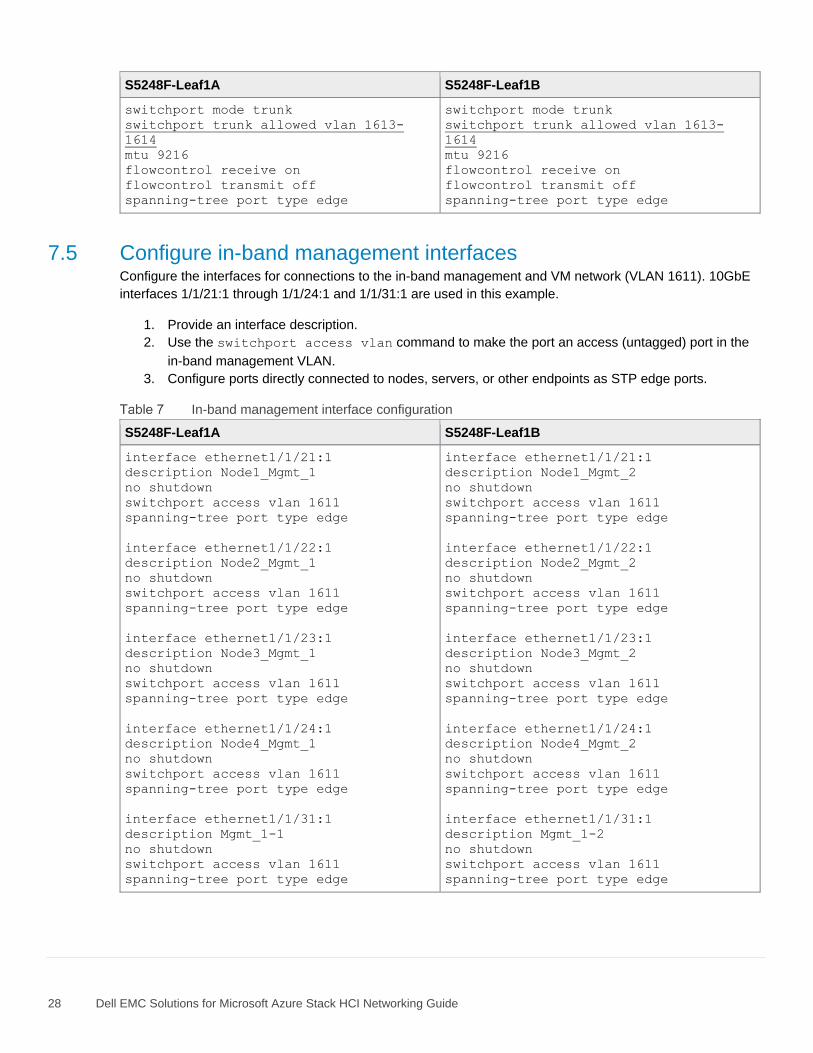
7.5 Configure in-band management interfaces Configure the interfaces for connections to the in-band management and VM network (VLAN 1611). 10GbE
interfaces 1/1/21:1 through 1/1/24:1 and 1/1/31:1 are used in this example.
1. Provide an interface description.
2. Use the switchport access vlan command to make the port an access (untagged) port in the
in-band management VLAN.
3. Configure ports directly connected to nodes, servers, or other endpoints as STP edge ports.
In-band management interface configuration
S5248F-Leaf1A S5248F-Leaf1B
interface ethernet1/1/21:1
description Node1_Mgmt_1
no shutdown
switchport access vlan 1611
spanning-tree port type edge
interface ethernet1/1/22:1
description Node2_Mgmt_1
no shutdown
switchport access vlan 1611
spanning-tree port type edge
interface ethernet1/1/23:1
description Node3_Mgmt_1
no shutdown
switchport access vlan 1611
spanning-tree port type edge
interface ethernet1/1/24:1
description Node4_Mgmt_1
no shutdown
switchport access vlan 1611
spanning-tree port type edge
interface ethernet1/1/31:1
description Mgmt_1-1
no shutdown
switchport access vlan 1611
spanning-tree port type edge
interface ethernet1/1/21:1
description Node1_Mgmt_2
no shutdown
switchport access vlan 1611
spanning-tree port type edge
interface ethernet1/1/22:1
description Node2_Mgmt_2
no shutdown
switchport access vlan 1611
spanning-tree port type edge
interface ethernet1/1/23:1
description Node3_Mgmt_2
no shutdown
switchport access vlan 1611
spanning-tree port type edge
interface ethernet1/1/24:1
description Node4_Mgmt_2
no shutdown
switchport access vlan 1611
spanning-tree port type edge
interface ethernet1/1/31:1
description Mgmt_1-2
no shutdown
switchport access vlan 1611
spanning-tree port type edge
29 Dell EMC Solutions for Microsoft Azure Stack HCI Networking Guide
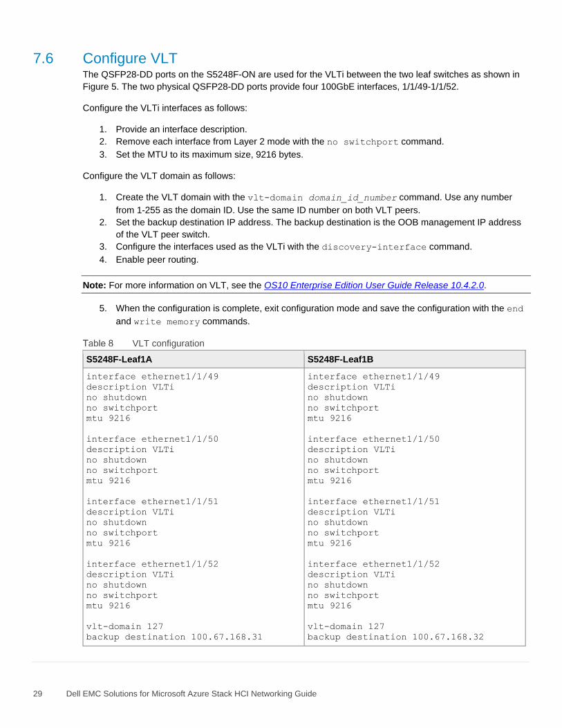
7.6 Configure VLT The QSFP28-DD ports on the S5248F-ON are used for the VLTi between the two leaf switches as shown in
Figure 5. The two physical QSFP28-DD ports provide four 100GbE interfaces, 1/1/49-1/1/52.
Configure the VLTi interfaces as follows:
1. Provide an interface description.
2. Remove each interface from Layer 2 mode with the no switchport command.
3. Set the MTU to its maximum size, 9216 bytes.
Configure the VLT domain as follows:
1. Create the VLT domain with the vlt-domain domain_id_number command. Use any number
from 1-255 as the domain ID. Use the same ID number on both VLT peers.
2. Set the backup destination IP address. The backup destination is the OOB management IP address
of the VLT peer switch.
3. Configure the interfaces used as the VLTi with the discovery-interface command.
4. Enable peer routing.
Note: For more information on VLT, see the OS10 Enterprise Edition User Guide Release 10.4.2.0.
5. When the configuration is complete, exit configuration mode and save the configuration with the end
and write memory commands.
VLT configuration
S5248F-Leaf1A S5248F-Leaf1B
interface ethernet1/1/49
description VLTi
no shutdown
no switchport
mtu 9216
interface ethernet1/1/50
description VLTi
no shutdown
no switchport
mtu 9216
interface ethernet1/1/51
description VLTi
no shutdown
no switchport
mtu 9216
interface ethernet1/1/52
description VLTi
no shutdown
no switchport
mtu 9216
vlt-domain 127
backup destination 100.67.168.31
interface ethernet1/1/49
description VLTi
no shutdown
no switchport
mtu 9216
interface ethernet1/1/50
description VLTi
no shutdown
no switchport
mtu 9216
interface ethernet1/1/51
description VLTi
no shutdown
no switchport
mtu 9216
interface ethernet1/1/52
description VLTi
no shutdown
no switchport
mtu 9216
vlt-domain 127
backup destination 100.67.168.32
30 Dell EMC Solutions for Microsoft Azure Stack HCI Networking Guide
S5248F-Leaf1A S5248F-Leaf1B
discovery-interface ethernet1/1/49-
1/1/52
peer-routing
end
write memory
discovery-interface ethernet1/1/49-
1/1/52
peer-routing
end
write memory
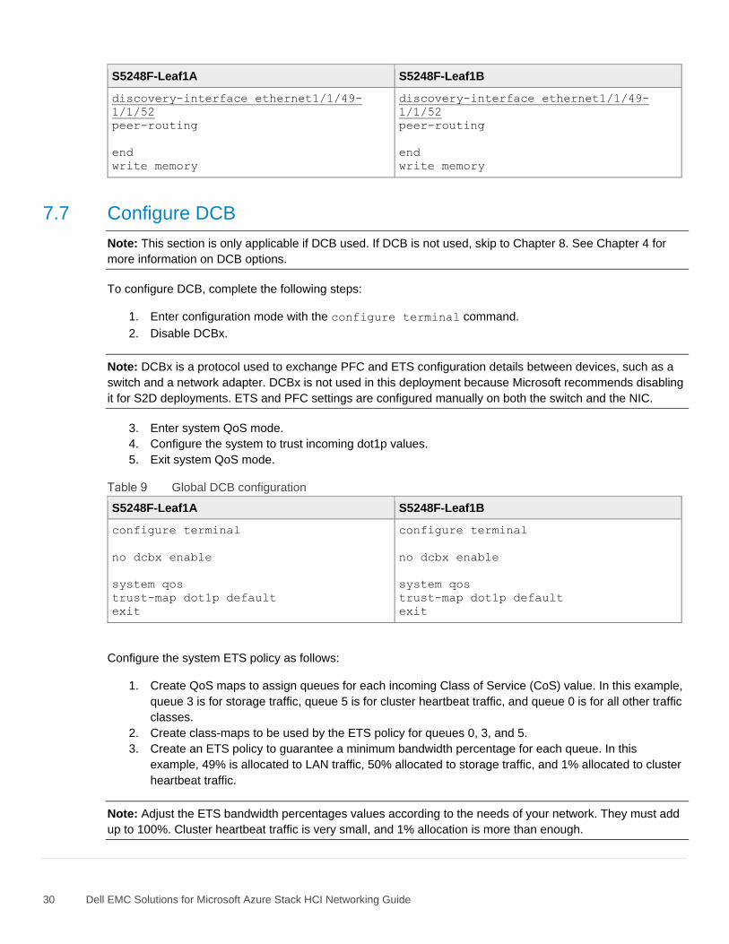
7.7 Configure DCB
Note: This section is only applicable if DCB used. If DCB is not used, skip to Chapter 8. See Chapter 4 for
more information on DCB options.
To configure DCB, complete the following steps:
1. Enter configuration mode with the configure terminal command.
2. Disable DCBx.
Note: DCBx is a protocol used to exchange PFC and ETS configuration details between devices, such as a
switch and a network adapter. DCBx is not used in this deployment because Microsoft recommends disabling
it for S2D deployments. ETS and PFC settings are configured manually on both the switch and the NIC.
3. Enter system QoS mode.
4. Configure the system to trust incoming dot1p values.
5. Exit system QoS mode.
Global DCB configuration
S5248F-Leaf1A S5248F-Leaf1B
configure terminal
no dcbx enable
system qos
trust-map dot1p default
exit
configure terminal
no dcbx enable
system qos
trust-map dot1p default
exit
Configure the system ETS policy as follows:
1. Create QoS maps to assign queues for each incoming Class of Service (CoS) value. In this example,
queue 3 is for storage traffic, queue 5 is for cluster heartbeat traffic, and queue 0 is for all other traffic
classes.
2. Create class-maps to be used by the ETS policy for queues 0, 3, and 5.
3. Create an ETS policy to guarantee a minimum bandwidth percentage for each queue. In this
example, 49% is allocated to LAN traffic, 50% allocated to storage traffic, and 1% allocated to cluster
heartbeat traffic.
Note: Adjust the ETS bandwidth percentages values according to the needs of your network. They must add
up to 100%. Cluster heartbeat traffic is very small, and 1% allocation is more than enough.
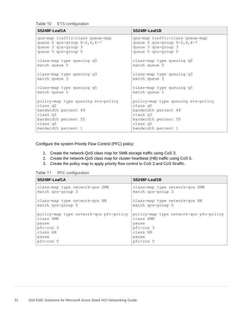
31 Dell EMC Solutions for Microsoft Azure Stack HCI Networking Guide
ETS configuration
S5248F-Leaf1A S5248F-Leaf1B
qos-map traffic-class queue-map
queue 0 qos-group 0-2,4,6-7
queue 3 qos-group 3
queue 5 qos-group 5
class-map type queuing q0
match queue 0
class-map type queuing q3
match queue 3
class-map type queuing q5
match queue 5
policy-map type queuing ets-policy
class q0
bandwidth percent 49
class q3
bandwidth percent 50
class q5
bandwidth percent 1
Configure the system Priority Flow Control (PFC) policy:
1. Create the network-QoS class map for SMB storage traffic using CoS 3.
2. Create the network-QoS class map for cluster heartbeat (HB) traffic using CoS 5.
3. Create the policy map to apply priority flow control to CoS 3 and CoS 5traffic.
PFC configuration
S5248F-Leaf1A S5248F-Leaf1B
class-map type network-qos SMB
match qos-group 3
class-map type network-qos HB
match qos-group 5
policy-map type network-qos pfc-policy
class SMB
pause
pfc-cos 3
class HB
pause
pfc-cos 5
class-map type network-qos SMB
match qos-group 3
class-map type network-qos HB
match qos-group 5
policy-map type network-qos pfc-policy
class SMB
pause
pfc-cos 3
class HB
pause
pfc-cos 5
32 Dell EMC Solutions for Microsoft Azure Stack HCI Networking Guide
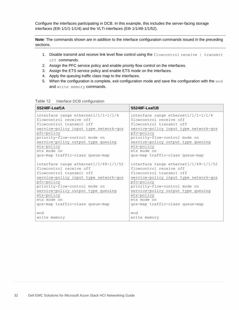
Configure the interfaces participating in DCB. In this example, this includes the server-facing storage
interfaces (Eth 1/1/1-1/1/4) and the VLTi interfaces (Eth 1/1/49-1/1/52).
Note: The commands shown are in addition to the interface configuration commands issued in the preceding
sections.
1. Disable transmit and receive link level flow control using the flowcontrol receive | transmit
off commands.
2. Assign the PFC service policy and enable priority flow control on the interfaces.
3. Assign the ETS service policy and enable ETS mode on the interfaces.
4. Apply the queuing traffic class map to the interfaces.
5. When the configuration is complete, exit configuration mode and save the configuration with the end
and write memory commands.
Interface DCB configuration
S5248F-Leaf1A S5248F-Leaf1B
interface range ethernet1/1/1-1/1/4
flowcontrol receive off
flowcontrol transmit off
service-policy input type network-qos
pfc-policy
priority-flow-control mode on
service-policy output type queuing
ets-policy
ets mode on
qos-map traffic-class queue-map
interface range ethernet1/1/49-1/1/52
flowcontrol receive off
flowcontrol transmit off
service-policy input type network-qos
pfc-policy
priority-flow-control mode on
service-policy output type queuing
ets-policy
ets mode on
qos-map traffic-class queue-map
end
write memory
33 Dell EMC Solutions for Microsoft Azure Stack HCI Networking Guide
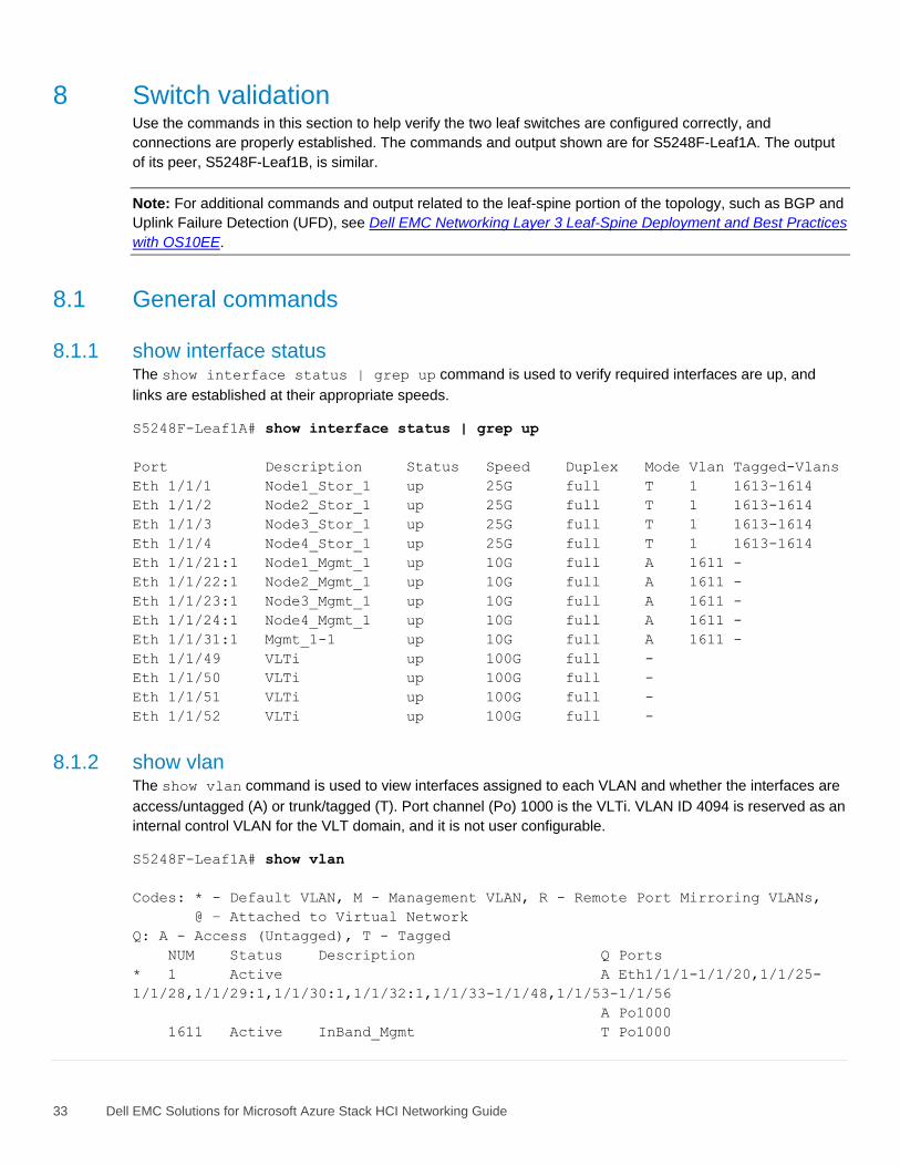
8 Switch validation Use the commands in this section to help verify the two leaf switches are configured correctly, and
connections are properly established. The commands and output shown are for S5248F-Leaf1A. The output
of its peer, S5248F-Leaf1B, is similar.
Note: For additional commands and output related to the leaf-spine portion of the topology, such as BGP and
Uplink Failure Detection (UFD), see Dell EMC Networking Layer 3 Leaf-Spine Deployment and Best Practices
with OS10EE.
8.1 General commands
8.1.1 show interface status The show interface status | grep up command is used to verify required interfaces are up, and
links are established at their appropriate speeds.
S5248F-Leaf1A# show interface status | grep up
Port Description Status Speed Duplex Mode Vlan Tagged-Vlans
Eth 1/1/1 Node1_Stor_1 up 25G full T 1 1613-1614
Eth 1/1/2 Node2_Stor_1 up 25G full T 1 1613-1614
Eth 1/1/3 Node3_Stor_1 up 25G full T 1 1613-1614
Eth 1/1/4 Node4_Stor_1 up 25G full T 1 1613-1614
Eth 1/1/21:1 Node1_Mgmt_1 up 10G full A 1611 -
Eth 1/1/22:1 Node2_Mgmt_1 up 10G full A 1611 -
Eth 1/1/23:1 Node3_Mgmt_1 up 10G full A 1611 -
Eth 1/1/24:1 Node4_Mgmt_1 up 10G full A 1611 -
Eth 1/1/31:1 Mgmt_1-1 up 10G full A 1611 -
Eth 1/1/49 VLTi up 100G full -
Eth 1/1/50 VLTi up 100G full -
Eth 1/1/51 VLTi up 100G full -
Eth 1/1/52 VLTi up 100G full -
8.1.2 show vlan The show vlan command is used to view interfaces assigned to each VLAN and whether the interfaces are
access/untagged (A) or trunk/tagged (T). Port channel (Po) 1000 is the VLTi. VLAN ID 4094 is reserved as an
internal control VLAN for the VLT domain, and it is not user configurable.
S5248F-Leaf1A# show vlan
Codes: * - Default VLAN, M - Management VLAN, R - Remote Port Mirroring VLANs,
@ – Attached to Virtual Network
Q: A - Access (Untagged), T - Tagged
NUM Status Description Q Ports
* 1 Active A Eth1/1/1-1/1/20,1/1/25-
1/1/28,1/1/29:1,1/1/30:1,1/1/32:1,1/1/33-1/1/48,1/1/53-1/1/56
A Po1000
1611 Active InBand_Mgmt T Po1000
34 Dell EMC Solutions for Microsoft Azure Stack HCI Networking Guide
A
Eth1/1/21:1,1/1/22:1,1/1/23:1,1/1/24:1,1/1/31:1
1613 Active Storage_1 T Eth1/1/1-1/1/4
T Po1000
1614 Active Storage_2 T Eth1/1/1-1/1/4
T Po1000
4094 Active T Po1000
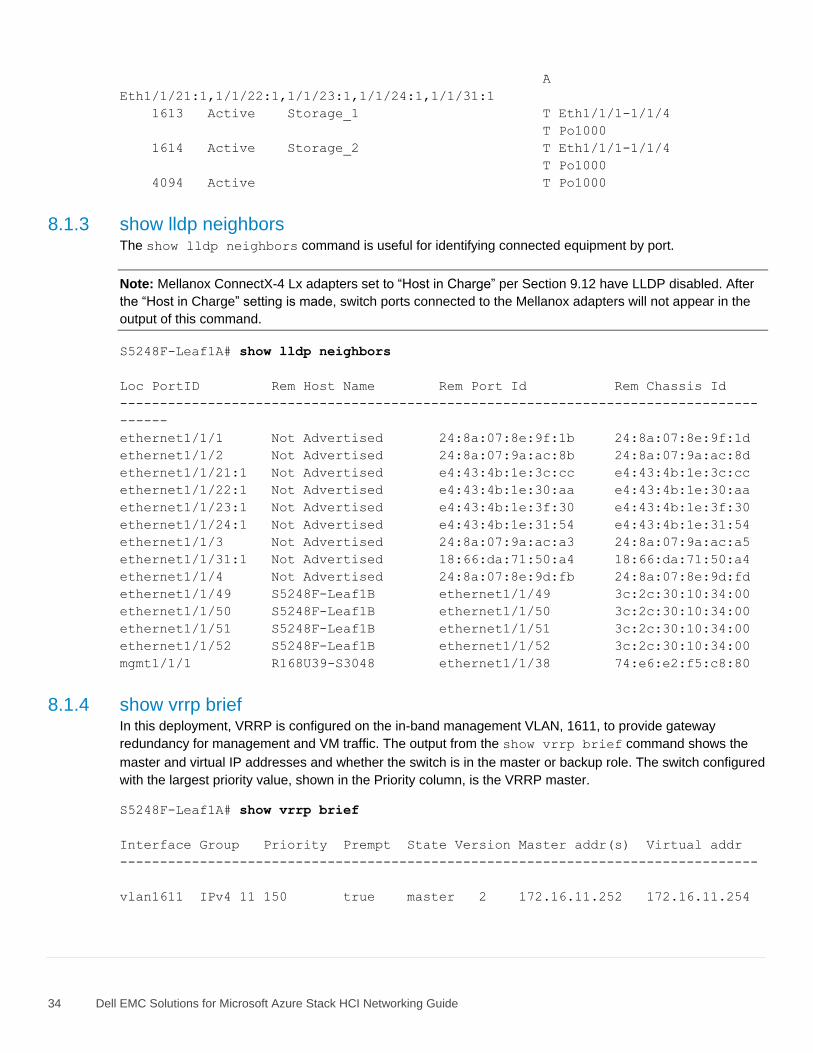
8.1.3 show lldp neighbors The show lldp neighbors command is useful for identifying connected equipment by port.
Note: Mellanox ConnectX-4 Lx adapters set to “Host in Charge” per Section 9.12 have LLDP disabled. After
the “Host in Charge” setting is made, switch ports connected to the Mellanox adapters will not appear in the
output of this command.
S5248F-Leaf1A# show lldp neighbors
Loc PortID Rem Host Name Rem Port Id Rem Chassis Id
--------------------------------------------------------------------------------
------
ethernet1/1/1 Not Advertised 24:8a:07:8e:9f:1b 24:8a:07:8e:9f:1d
ethernet1/1/2 Not Advertised 24:8a:07:9a:ac:8b 24:8a:07:9a:ac:8d
ethernet1/1/21:1 Not Advertised e4:43:4b:1e:3c:cc e4:43:4b:1e:3c:cc
ethernet1/1/22:1 Not Advertised e4:43:4b:1e:30:aa e4:43:4b:1e:30:aa
ethernet1/1/23:1 Not Advertised e4:43:4b:1e:3f:30 e4:43:4b:1e:3f:30
ethernet1/1/24:1 Not Advertised e4:43:4b:1e:31:54 e4:43:4b:1e:31:54
ethernet1/1/3 Not Advertised 24:8a:07:9a:ac:a3 24:8a:07:9a:ac:a5
ethernet1/1/31:1 Not Advertised 18:66:da:71:50:a4 18:66:da:71:50:a4
ethernet1/1/4 Not Advertised 24:8a:07:8e:9d:fb 24:8a:07:8e:9d:fd
ethernet1/1/49 S5248F-Leaf1B ethernet1/1/49 3c:2c:30:10:34:00
ethernet1/1/50 S5248F-Leaf1B ethernet1/1/50 3c:2c:30:10:34:00
ethernet1/1/51 S5248F-Leaf1B ethernet1/1/51 3c:2c:30:10:34:00
ethernet1/1/52 S5248F-Leaf1B ethernet1/1/52 3c:2c:30:10:34:00
mgmt1/1/1 R168U39-S3048 ethernet1/1/38 74:e6:e2:f5:c8:80
8.1.4 show vrrp brief In this deployment, VRRP is configured on the in-band management VLAN, 1611, to provide gateway
redundancy for management and VM traffic. The output from the show vrrp brief command shows the
master and virtual IP addresses and whether the switch is in the master or backup role. The switch configured
with the largest priority value, shown in the Priority column, is the VRRP master.
S5248F-Leaf1A# show vrrp brief
Interface Group Priority Prempt State Version Master addr(s) Virtual addr
--------------------------------------------------------------------------------
vlan1611 IPv4 11 150 true master 2 172.16.11.252 172.16.11.254
35 Dell EMC Solutions for Microsoft Azure Stack HCI Networking Guide
8.2 VLT validation commands
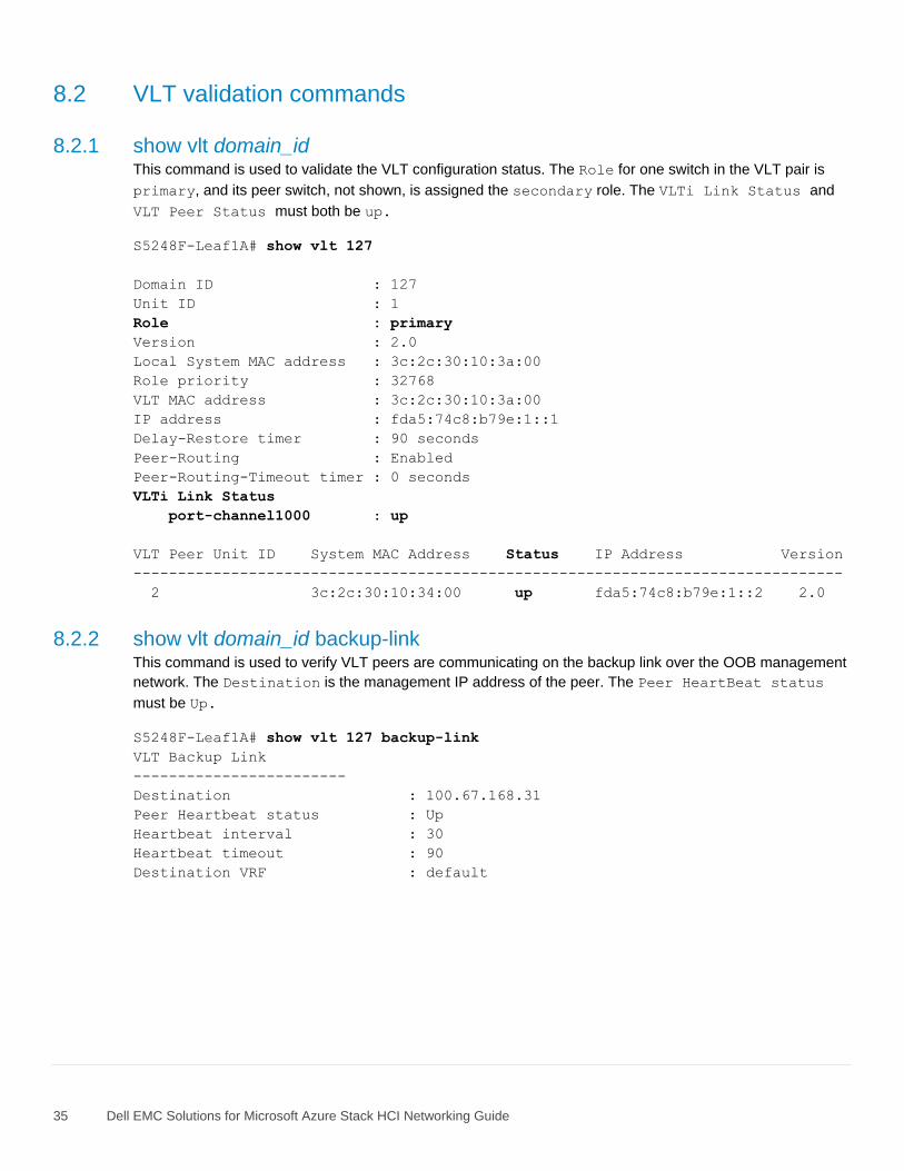
8.2.1 show vlt domain_id This command is used to validate the VLT configuration status. The Role for one switch in the VLT pair is
primary, and its peer switch, not shown, is assigned the secondary role. The VLTi Link Status and
VLT Peer Status must both be up.
S5248F-Leaf1A# show vlt 127
Domain ID : 127
Unit ID : 1
Role : primary
Version : 2.0
Local System MAC address : 3c:2c:30:10:3a:00
Role priority : 32768
VLT MAC address : 3c:2c:30:10:3a:00
IP address : fda5:74c8:b79e:1::1
Delay-Restore timer : 90 seconds
Peer-Routing : Enabled
Peer-Routing-Timeout timer : 0 seconds
VLTi Link Status
port-channel1000 : up
VLT Peer Unit ID System MAC Address Status IP Address Version
--------------------------------------------------------------------------------
2 3c:2c:30:10:34:00 up fda5:74c8:b79e:1::2 2.0
8.2.2 show vlt domain_id backup-link This command is used to verify VLT peers are communicating on the backup link over the OOB management
network. The Destination is the management IP address of the peer. The Peer HeartBeat status
must be Up.
S5248F-Leaf1A# show vlt 127 backup-link
VLT Backup Link
------------------------
Destination : 100.67.168.31
Peer Heartbeat status : Up
Heartbeat interval : 30
Heartbeat timeout : 90
Destination VRF : default
36 Dell EMC Solutions for Microsoft Azure Stack HCI Networking Guide
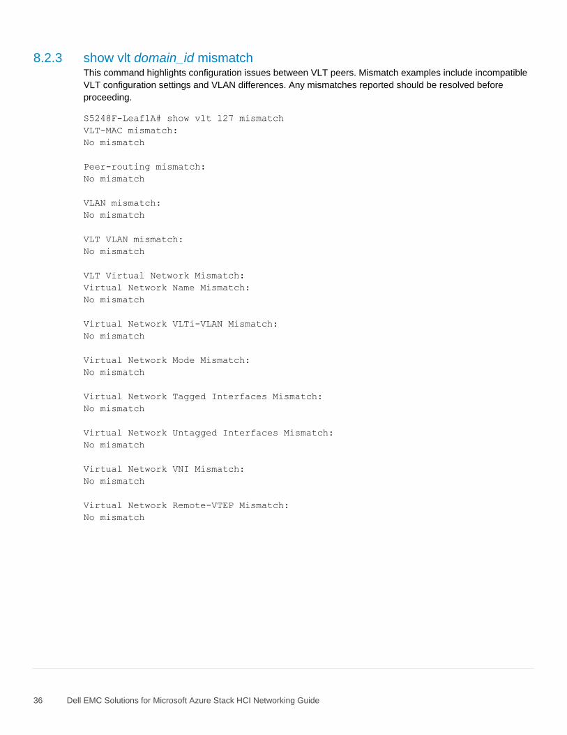
8.2.3 show vlt domain_id mismatch This command highlights configuration issues between VLT peers. Mismatch examples include incompatible
VLT configuration settings and VLAN differences. Any mismatches reported should be resolved before
proceeding.
S5248F-Leaf1A# show vlt 127 mismatch
VLT-MAC mismatch:
No mismatch
Peer-routing mismatch:
No mismatch
VLAN mismatch:
No mismatch
VLT VLAN mismatch:
No mismatch
VLT Virtual Network Mismatch:
Virtual Network Name Mismatch:
No mismatch
Virtual Network VLTi-VLAN Mismatch:
No mismatch
Virtual Network Mode Mismatch:
No mismatch
Virtual Network Tagged Interfaces Mismatch:
No mismatch
Virtual Network Untagged Interfaces Mismatch:
No mismatch
Virtual Network VNI Mismatch:
No mismatch
Virtual Network Remote-VTEP Mismatch:
No mismatch
37 Dell EMC Solutions for Microsoft Azure Stack HCI Networking Guide
9 S2D Ready Node configuration and deployment These steps are applicable to Windows Server 2016 or 2019 Datacenter with Server Core or Server with
Desktop Experience installations.
The network adapter names shown in the command examples may vary depending on adapters installed in
the system. For PowerShell commands that require a network adapter name, use the Get-NetAdapter
cmdlet to retrieve the name for the associated port.
Note: This chapter ends with Section 9.13 - Configure DCB on Ready Nodes. If DCB is used in your
deployment, follow the steps in Sections 9.1-9.13. If DCB is not used, follow the steps in Sections 9.1-9.12.
Note: All PowerShell command examples in this guide are run as Administrator. For more information on the
commands used, see the Microsoft Storage Spaces Direct documentation, the Microsoft Windows Server
2016 and 2019 RDMA Deployment Guide, and the Dell EMC Solutions for Microsoft Azure Stack HCI
Deployment Guide.
9.1 Initial state The S2D Ready Nodes and management system in this deployment start at the following state:
• The same version of Windows Server Datacenter is installed on the management system and
Ready Nodes. See Appendix A.4 for Windows Server versions validated for this guide.
• The latest Windows updates are installed on each system.
• All device firmware and drivers on the Ready Nodes are up-to-date and are at the same or later
versions as those listed in the Support Matrix for Dell EMC Solutions for Microsoft Azure Stack
HCI.
Note: The QLogic QL41262 adapter may not include a preinstalled driver with Windows Server 2016.
• Each Ready Node has been configured with a user-friendly hostname. In this example, the four
nodes are named storage-01 through storage-04. This can be done with the Rename-Computer
cmdlet as follows:
PS> Rename-Computer –NewName storage-01 -Restart
Note: All Ready Nodes are joined to the same Active Directory domain in Section 9.6.
38 Dell EMC Solutions for Microsoft Azure Stack HCI Networking Guide
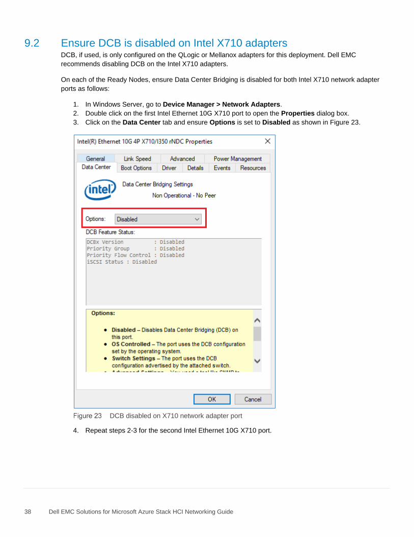
9.2 Ensure DCB is disabled on Intel X710 adapters DCB, if used, is only configured on the QLogic or Mellanox adapters for this deployment. Dell EMC
recommends disabling DCB on the Intel X710 adapters.
On each of the Ready Nodes, ensure Data Center Bridging is disabled for both Intel X710 network adapter
ports as follows:
1. In Windows Server, go to Device Manager > Network Adapters.
2. Double click on the first Intel Ethernet 10G X710 port to open the Properties dialog box.
3. Click on the Data Center tab and ensure Options is set to Disabled as shown in Figure 23.
DCB disabled on X710 network adapter port
4. Repeat steps 2-3 for the second Intel Ethernet 10G X710 port.
39 Dell EMC Solutions for Microsoft Azure Stack HCI Networking Guide
9.3 Install roles and features On each of the Ready Nodes, install the Hyper-V, Failover Clustering, and, if DCB is used, the Data Center
Bridging roles and features using the Install-WindowsFeature PowerShell cmdlet. The command below
also installs the management tools for Hyper-V and Failover Clustering and restarts the system.
PS> Install-WindowsFeature -Name Hyper-V, Failover-Clustering, Data-
Center-Bridging -IncludeAllSubFeature -IncludeManagementTools –Verbose -
Restart
On the management system, only the management tools for Hyper-V and Failover Clustering need to be
installed. Tools are installed, and the system restarted with the following command:
PS> Install-WindowsFeature -Name Hyper-V-Tools, Hyper-V-PowerShell, RSAT-
Clustering-PowerShell, RSAT-Clustering-Mgmt -Verbose -Restart
Note: For this example, the management system is also the Active Directory domain controller and DNS
server. To install these features using the Install-WindowsFeature cmdlet, the -Name parameters are
AD-Domain-Services and DNS respectively.
9.4 Configure the in-band management and VM network In this section, the in-band management and VM network, VLAN 1611, is configured. The IP addresses used
are from Table 3. To validate the commands below have taken effect, the associated Get- cmdlets and
output examples are listed in Chapter 10.
Note: On WS2016, the default SET load balancing method is Dynamic. On WS2019, the default SET load
balancing method is Hyper-V Port. Default load balancing methods are used in the examples in this guide.
1. In PowerShell, run the New-VMSwitch cmdlet on each Ready Node to create a SET switch. It is
named ProdSwitch in this example.
PS> New-VMSwitch -Name ProdSwitch -AllowManagementOS 0 -NetAdapterName
'NIC1','NIC2' -MinimumBandwidthMode Weight -Verbose
Note: Retrieve the argument for the NetAdapterName parameters by using the Get-NetAdapter cmdlet in
PowerShell. Use the adapters connected to the in-band management network. These are the 10GbE Intel
X710 adapters named NIC1 and NIC2 in this example.
2. Run the following command on each Ready Node to create the VM network adapter for the in-band
management and VM network VLAN (VLAN 1611).
PS> Add-VMNetworkAdapter -ManagementOS -Name 'Management' -SwitchName
ProdSwitch -Passthru -Verbose | Set-VMNetworkAdapterVlan -Untagged –
Verbose
3. Configure the Ready Node IP address and default gateway for the in-band management network with
the following command:
PS> New-NetIPAddress -InterfaceAlias ‘vEthernet (Management)’ -IPAddress
172.16.11.1 -DefaultGateway 172.16.11.254 -PrefixLength 24 -AddressFamily
IPv4 –Verbose
40 Dell EMC Solutions for Microsoft Azure Stack HCI Networking Guide
The example above is for Ready Node 1. IP addresses used for the Ready Nodes are listed in Table 3. The
default gateway is set to the leaf pair’s VRRP address, 172.16.11.254.
4. Configure the DNS server address on each Ready Node.
PS> Set-DnsClientServerAddress -InterfaceAlias ‘vEthernet (Management)’ -
ServerAddresses 172.16.11.5
Note: Since the management system is not running Hyper-V, its two 10GbE NICs connected to the leaf
switches are simply configured as a switch independent NIC team. The IP address of the NIC team used in
this example is 172.16.11.5/24.
9.5 Configure storage networks
Run the following commands on each Ready Node to configure VLANs and IP addresses on the 25GbE
physical network adapters for Storage 1 and Storage 2 traffic. The VLAN IDs and IP addresses shown are
from Table 3. To validate the commands below have taken effect, the associated Get- cmdlets and output
examples are listed in Chapter 10.
Note: Use the Get-NetAdapter cmdlet in PowerShell to determine the network adapter port name used in
the commands. These commands are not run on the management system as it is not part of the S2D cluster.
9.5.1 Configure storage VLANs The following commands assign port 1 on the 25GbE network adapter to VLAN 1613 and port 2 to VLAN
1614.
PS> Set-NetAdapterAdvancedProperty 'SLOT 2 PORT 1' -RegistryKeyword VlanID -RegistryValue "1613"
PS> Set-NetAdapterAdvancedProperty 'SLOT 2 PORT 2' -RegistryKeyword VlanID -RegistryValue "1614"
9.5.2 Configure storage IP addresses The following commands configure the IP address and subnet mask for the two storage network adapter
ports. The IP addresses shown are specific to Ready Node 1.
PS> New-NetIPAddress -InterfaceAlias 'SLOT 2 PORT 1' -IPAddress 172.16.13.1 -PrefixLength 24
PS> New-NetIPAddress -InterfaceAlias 'SLOT 2 PORT 2' -IPAddress 172.16.14.1 -PrefixLength 24
41 Dell EMC Solutions for Microsoft Azure Stack HCI Networking Guide
9.5.3 Enable RDMA RDMA is enabled on each storage network adapter port with the Enable-NetAdapterRdma cmdlet. The
wildcard (*) may be used because the same command applies to both ports in slot 2.
PS> Enable-NetAdapterRdma -Name 'SLOT 2*'
RDMA is enabled for Live Migration traffic with the following PowerShell command:
PS> Set-VMHost –VirtualMachineMigrationPerformanceOption SMB
9.5.4 Enable iWARP on QLogic adapters
Note: Skip this step for Mellanox adapters because they do not use iWARP. The command syntax varies
depending on the Windows Server version installed as shown below.
To set the RDMA mode to iWARP on QLogic storage adapters, run the following commands on each Ready
Node:
On Windows Server 2016:
PS> Set-NetAdapterAdvancedProperty -Name 'SLOT 2 PORT 1' -DisplayName
'RDMA Mode' -DisplayValue 'iWARP'
PS> Set-NetAdapterAdvancedProperty -Name 'SLOT 2 PORT 2' -DisplayName
'RDMA Mode' -DisplayValue 'iWARP'
On Windows Server 2019:
PS> Set-NetAdapterAdvancedProperty -Name 'SLOT 2 PORT 1' -DisplayName
'NetworkDirect Technology' -displayvalue 'iWARP'
PS> Set-NetAdapterAdvancedProperty -Name 'SLOT 2 PORT 2' -DisplayName
'NetworkDirect Technology' -displayvalue 'iWARP'
9.5.5 Enable jumbo frames on NICs In this deployment, jumbo frames are enabled on NICs that carry storage traffic for best performance.
QLogic QL41262 and Mellanox ConnectX-4 Lx adapters support setting the jumbo frame size to 9014 bytes.
Sizes allowed by other NIC makes and models may vary.
Enable jumbo frames of up to 9014 bytes on the storage NIC ports with the command:
PS> Set-NetAdapterAdvancedProperty -Name 'SLOT 2*' -RegistryKeyword
'*JumboPacket' -RegistryValue '9014'
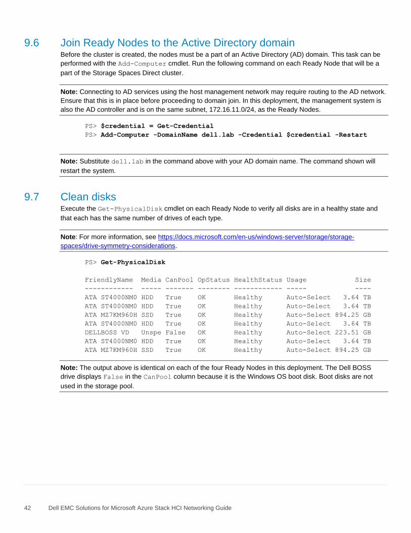
42 Dell EMC Solutions for Microsoft Azure Stack HCI Networking Guide
9.6 Join Ready Nodes to the Active Directory domain Before the cluster is created, the nodes must be a part of an Active Directory (AD) domain. This task can be
performed with the Add-Computer cmdlet. Run the following command on each Ready Node that will be a
part of the Storage Spaces Direct cluster.
Note: Connecting to AD services using the host management network may require routing to the AD network.
Ensure that this is in place before proceeding to domain join. In this deployment, the management system is
also the AD controller and is on the same subnet, 172.16.11.0/24, as the Ready Nodes.
PS> $credential = Get-Credential
PS> Add-Computer -DomainName dell.lab -Credential $credential -Restart
Note: Substitute dell.lab in the command above with your AD domain name. The command shown will
restart the system.
9.7 Clean disks Execute the Get-PhysicalDisk cmdlet on each Ready Node to verify all disks are in a healthy state and
that each has the same number of drives of each type.
Note: For more information, see https://docs.microsoft.com/en-us/windows-server/storage/storage-
spaces/drive-symmetry-considerations.
PS> Get-PhysicalDisk
FriendlyName Media CanPool OpStatus HealthStatus Usage Size
------------ ----- ------- -------- ------------ ----- ----
ATA ST4000NM0 HDD True OK Healthy Auto-Select 3.64 TB
ATA ST4000NM0 HDD True OK Healthy Auto-Select 3.64 TB
ATA MZ7KM960H SSD True OK Healthy Auto-Select 894.25 GB
ATA ST4000NM0 HDD True OK Healthy Auto-Select 3.64 TB
DELLBOSS VD Unspe False OK Healthy Auto-Select 223.51 GB
ATA ST4000NM0 HDD True OK Healthy Auto-Select 3.64 TB
ATA MZ7KM960H SSD True OK Healthy Auto-Select 894.25 GB
Note: The output above is identical on each of the four Ready Nodes in this deployment. The Dell BOSS
drive displays False in the CanPool column because it is the Windows OS boot disk. Boot disks are not
used in the storage pool.
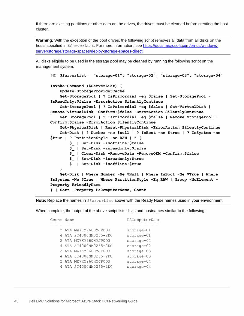
43 Dell EMC Solutions for Microsoft Azure Stack HCI Networking Guide
If there are existing partitions or other data on the drives, the drives must be cleaned before creating the host
cluster.
Warning: With the exception of the boot drives, the following script removes all data from all disks on the
hosts specified in $ServerList. For more information, see https://docs.microsoft.com/en-us/windows-
server/storage/storage-spaces/deploy-storage-spaces-direct.
All disks eligible to be used in the storage pool may be cleaned by running the following script on the
management system:
PS> $ServerList = "storage-01", "storage-02", "storage-03", "storage-04"
Invoke-Command ($ServerList) {
Update-StorageProviderCache
Get-StoragePool | ? IsPrimordial -eq $false | Set-StoragePool -
IsReadOnly:$false -ErrorAction SilentlyContinue
Get-StoragePool | ? IsPrimordial -eq $false | Get-VirtualDisk |
Remove-VirtualDisk -Confirm:$false -ErrorAction SilentlyContinue
Get-StoragePool | ? IsPrimordial -eq $false | Remove-StoragePool -
Confirm:$false -ErrorAction SilentlyContinue
Get-PhysicalDisk | Reset-PhysicalDisk -ErrorAction SilentlyContinue
Get-Disk | ? Number -ne $null | ? IsBoot -ne $true | ? IsSystem -ne
$true | ? PartitionStyle -ne RAW | % {
$_ | Set-Disk -isoffline:$false
$_ | Set-Disk -isreadonly:$false
$_ | Clear-Disk -RemoveData -RemoveOEM -Confirm:$false
$_ | Set-Disk -isreadonly:$true
$_ | Set-Disk -isoffline:$true
}
Get-Disk | Where Number -Ne $Null | Where IsBoot -Ne $True | Where
IsSystem -Ne $True | Where PartitionStyle -Eq RAW | Group -NoElement -
Property FriendlyName
} | Sort -Property PsComputerName, Count
Note: Replace the names in $ServerList above with the Ready Node names used in your environment.
When complete, the output of the above script lists disks and hostnames similar to the following:
Count Name PSComputerName
----- ---- --------------
2 ATA MZ7KM960HMJP0D3 storage-01
4 ATA ST4000NM0265-2DC storage-01
2 ATA MZ7KM960HMJP0D3 storage-02
4 ATA ST4000NM0265-2DC storage-02
2 ATA MZ7KM960HMJP0D3 storage-03
4 ATA ST4000NM0265-2DC storage-03
2 ATA MZ7KM960HMJP0D3 storage-04
4 ATA ST4000NM0265-2DC storage-04
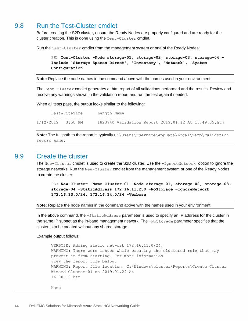
44 Dell EMC Solutions for Microsoft Azure Stack HCI Networking Guide
9.8 Run the Test-Cluster cmdlet Before creating the S2D cluster, ensure the Ready Nodes are properly configured and are ready for the
cluster creation. This is done using the Test-Cluster cmdlet.
Run the Test-Cluster cmdlet from the management system or one of the Ready Nodes:
PS> Test-Cluster -Node storage-01, storage-02, storage-03, storage-04 –
Include 'Storage Spaces Direct', 'Inventory', 'Network', 'System
Configuration'
Note: Replace the node names in the command above with the names used in your environment.
The Test-Cluster cmdlet generates a .htm report of all validations performed and the results. Review and
resolve any warnings shown in the validation report and run the test again if needed.
When all tests pass, the output looks similar to the following:
LastWriteTime Length Name
------------- ------ ----
1/12/2019 3:50 PM 1823740 Validation Report 2019.01.12 At 15.49.35.htm
Note: The full path to the report is typically C:\Users\username\AppData\Local\Temp\validation
report name.
9.9 Create the cluster The New-Cluster cmdlet is used to create the S2D cluster. Use the -IgnoreNetwork option to ignore the
storage networks. Run the New-Cluster cmdlet from the management system or one of the Ready Nodes
to create the cluster:
PS> New-Cluster –Name Cluster-01 –Node storage-01, storage-02, storage-03,
storage-04 -StaticAddress 172.16.11.250 –NoStorage –IgnoreNetwork
172.16.13.0/24, 172.16.14.0/24 -Verbose
Note: Replace the node names in the command above with the names used in your environment.
In the above command, the -StaticAddress parameter is used to specify an IP address for the cluster in
the same IP subnet as the in-band management network. The -NoStorage parameter specifies that the
cluster is to be created without any shared storage.
Example output follows:
VERBOSE: Adding static network 172.16.11.0/24.
WARNING: There were issues while creating the clustered role that may
prevent it from starting. For more information
view the report file below.
WARNING: Report file location: C:\Windows\cluster\Reports\Create Cluster
Wizard Cluster-01 on 2019.01.29 At
16.00.10.htm
Name
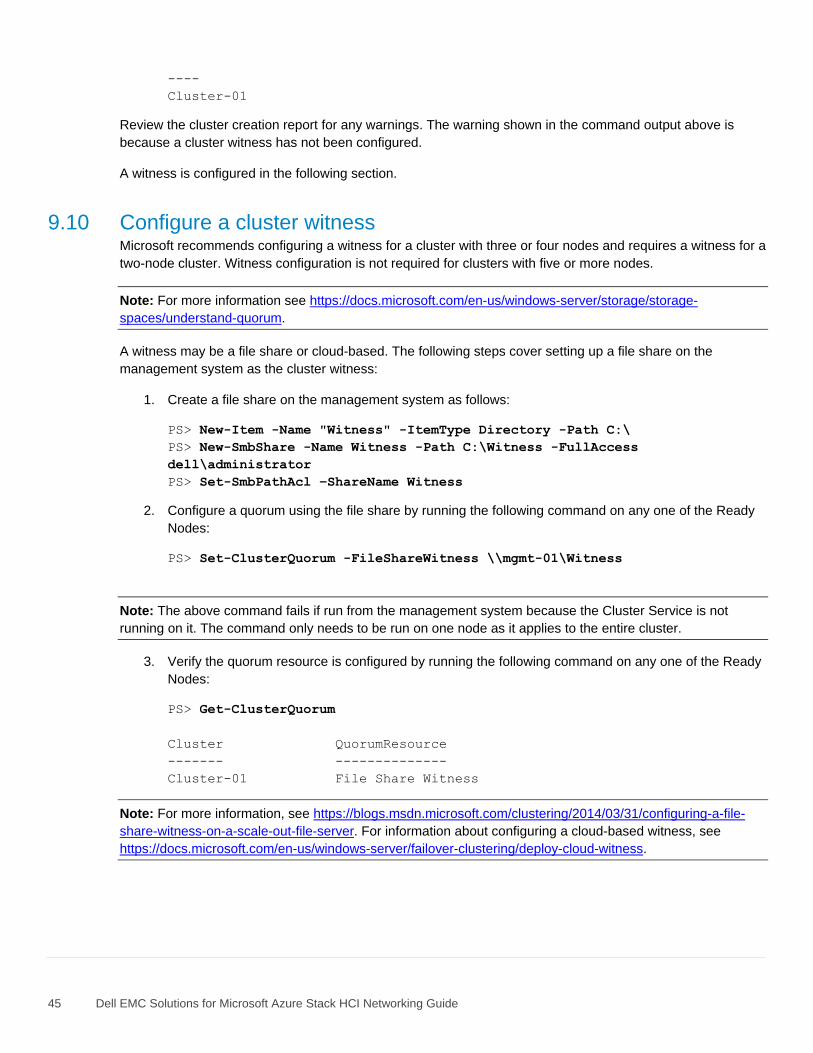
45 Dell EMC Solutions for Microsoft Azure Stack HCI Networking Guide
----
Cluster-01
Review the cluster creation report for any warnings. The warning shown in the command output above is
because a cluster witness has not been configured.
A witness is configured in the following section.
9.10 Configure a cluster witness Microsoft recommends configuring a witness for a cluster with three or four nodes and requires a witness for a
two-node cluster. Witness configuration is not required for clusters with five or more nodes.
Note: For more information see https://docs.microsoft.com/en-us/windows-server/storage/storage-
spaces/understand-quorum.
A witness may be a file share or cloud-based. The following steps cover setting up a file share on the
management system as the cluster witness:
1. Create a file share on the management system as follows:
PS> New-Item -Name "Witness" -ItemType Directory -Path C:\
PS> New-SmbShare -Name Witness -Path C:\Witness -FullAccess
dell\administrator
PS> Set-SmbPathAcl –ShareName Witness
2. Configure a quorum using the file share by running the following command on any one of the Ready
Nodes:
PS> Set-ClusterQuorum -FileShareWitness \\mgmt-01\Witness
Note: The above command fails if run from the management system because the Cluster Service is not
running on it. The command only needs to be run on one node as it applies to the entire cluster.
3. Verify the quorum resource is configured by running the following command on any one of the Ready
Nodes:
PS> Get-ClusterQuorum
Cluster QuorumResource
------- --------------
Cluster-01 File Share Witness
Note: For more information, see https://blogs.msdn.microsoft.com/clustering/2014/03/31/configuring-a-file-
share-witness-on-a-scale-out-file-server. For information about configuring a cloud-based witness, see
https://docs.microsoft.com/en-us/windows-server/failover-clustering/deploy-cloud-witness.
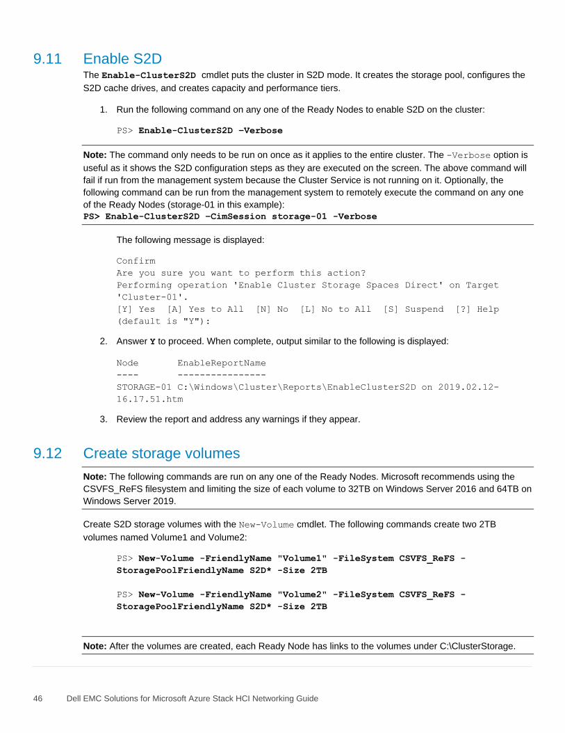
46 Dell EMC Solutions for Microsoft Azure Stack HCI Networking Guide
9.11 Enable S2D The Enable-ClusterS2D cmdlet puts the cluster in S2D mode. It creates the storage pool, configures the
S2D cache drives, and creates capacity and performance tiers.
1. Run the following command on any one of the Ready Nodes to enable S2D on the cluster:
PS> Enable-ClusterS2D –Verbose
Note: The command only needs to be run on once as it applies to the entire cluster. The -Verbose option is
useful as it shows the S2D configuration steps as they are executed on the screen. The above command will
fail if run from the management system because the Cluster Service is not running on it. Optionally, the
following command can be run from the management system to remotely execute the command on any one
of the Ready Nodes (storage-01 in this example):
PS> Enable-ClusterS2D –CimSession storage-01 -Verbose
The following message is displayed:
Confirm
Are you sure you want to perform this action?
Performing operation 'Enable Cluster Storage Spaces Direct' on Target
'Cluster-01'.
[Y] Yes [A] Yes to All [N] No [L] No to All [S] Suspend [?] Help
(default is "Y"):
2. Answer Y to proceed. When complete, output similar to the following is displayed:
Node EnableReportName
---- ----------------
STORAGE-01 C:\Windows\Cluster\Reports\EnableClusterS2D on 2019.02.12-
16.17.51.htm
3. Review the report and address any warnings if they appear.
9.12 Create storage volumes
Note: The following commands are run on any one of the Ready Nodes. Microsoft recommends using the
CSVFS_ReFS filesystem and limiting the size of each volume to 32TB on Windows Server 2016 and 64TB on
Windows Server 2019.
Create S2D storage volumes with the New-Volume cmdlet. The following commands create two 2TB
volumes named Volume1 and Volume2:
PS> New-Volume -FriendlyName "Volume1" -FileSystem CSVFS_ReFS -
StoragePoolFriendlyName S2D* -Size 2TB
PS> New-Volume -FriendlyName "Volume2" -FileSystem CSVFS_ReFS -
StoragePoolFriendlyName S2D* -Size 2TB
Note: After the volumes are created, each Ready Node has links to the volumes under C:\ClusterStorage.
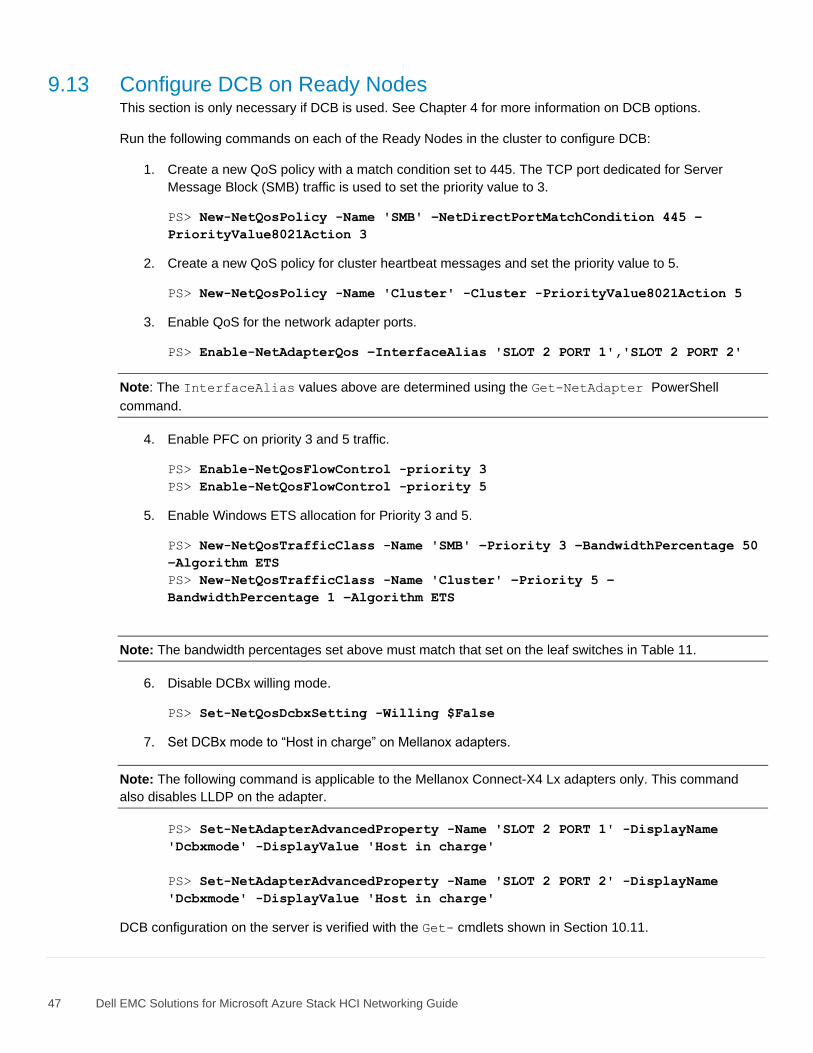
47 Dell EMC Solutions for Microsoft Azure Stack HCI Networking Guide
9.13 Configure DCB on Ready Nodes This section is only necessary if DCB is used. See Chapter 4 for more information on DCB options.
Run the following commands on each of the Ready Nodes in the cluster to configure DCB:
1. Create a new QoS policy with a match condition set to 445. The TCP port dedicated for Server
Message Block (SMB) traffic is used to set the priority value to 3.
PS> New-NetQosPolicy -Name 'SMB' –NetDirectPortMatchCondition 445 –
PriorityValue8021Action 3
2. Create a new QoS policy for cluster heartbeat messages and set the priority value to 5.
PS> New-NetQosPolicy -Name 'Cluster' -Cluster -PriorityValue8021Action 5
3. Enable QoS for the network adapter ports.
PS> Enable-NetAdapterQos –InterfaceAlias 'SLOT 2 PORT 1','SLOT 2 PORT 2'
Note: The InterfaceAlias values above are determined using the Get-NetAdapter PowerShell
command.
4. Enable PFC on priority 3 and 5 traffic.
PS> Enable-NetQosFlowControl -priority 3
PS> Enable-NetQosFlowControl -priority 5
5. Enable Windows ETS allocation for Priority 3 and 5.
PS> New-NetQosTrafficClass -Name 'SMB' –Priority 3 –BandwidthPercentage 50
–Algorithm ETS
PS> New-NetQosTrafficClass -Name 'Cluster' –Priority 5 –
BandwidthPercentage 1 –Algorithm ETS
Note: The bandwidth percentages set above must match that set on the leaf switches in Table 11.
6. Disable DCBx willing mode.
PS> Set-NetQosDcbxSetting -Willing $False
7. Set DCBx mode to “Host in charge” on Mellanox adapters.
Note: The following command is applicable to the Mellanox Connect-X4 Lx adapters only. This command
also disables LLDP on the adapter.
PS> Set-NetAdapterAdvancedProperty -Name 'SLOT 2 PORT 1' -DisplayName
'Dcbxmode' -DisplayValue 'Host in charge'
PS> Set-NetAdapterAdvancedProperty -Name 'SLOT 2 PORT 2' -DisplayName
'Dcbxmode' -DisplayValue 'Host in charge'
DCB configuration on the server is verified with the Get- cmdlets shown in Section 10.11.
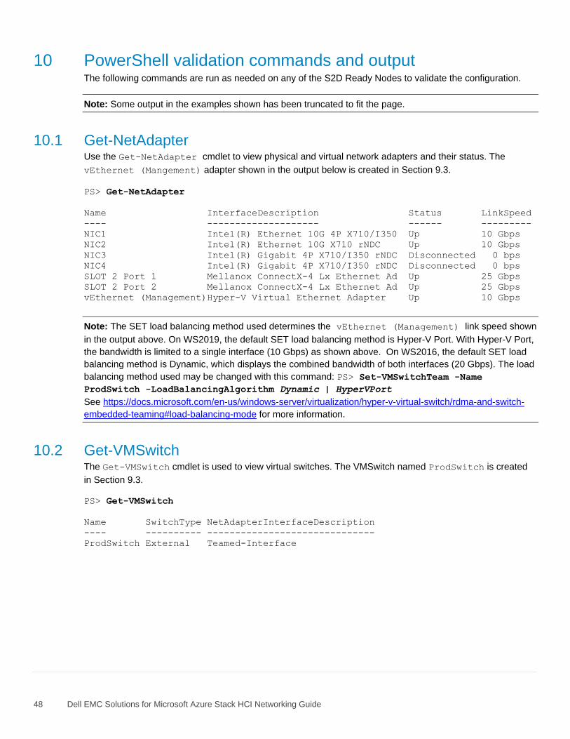
48 Dell EMC Solutions for Microsoft Azure Stack HCI Networking Guide
10 PowerShell validation commands and output The following commands are run as needed on any of the S2D Ready Nodes to validate the configuration.
Note: Some output in the examples shown has been truncated to fit the page.
10.1 Get-NetAdapter Use the Get-NetAdapter cmdlet to view physical and virtual network adapters and their status. The
vEthernet (Mangement) adapter shown in the output below is created in Section 9.3.
PS> Get-NetAdapter
Name InterfaceDescription Status LinkSpeed
---- -------------------- ------ ---------
NIC1 Intel(R) Ethernet 10G 4P X710/I350 Up 10 Gbps
NIC2 Intel(R) Ethernet 10G X710 rNDC Up 10 Gbps
NIC3 Intel(R) Gigabit 4P X710/I350 rNDC Disconnected 0 bps
NIC4 Intel(R) Gigabit 4P X710/I350 rNDC Disconnected 0 bps
SLOT 2 Port 1 Mellanox ConnectX-4 Lx Ethernet Ad Up 25 Gbps
SLOT 2 Port 2 Mellanox ConnectX-4 Lx Ethernet Ad Up 25 Gbps
vEthernet (Management)Hyper-V Virtual Ethernet Adapter Up 10 Gbps
Note: The SET load balancing method used determines the vEthernet (Management) link speed shown
in the output above. On WS2019, the default SET load balancing method is Hyper-V Port. With Hyper-V Port,
the bandwidth is limited to a single interface (10 Gbps) as shown above. On WS2016, the default SET load
balancing method is Dynamic, which displays the combined bandwidth of both interfaces (20 Gbps). The load
balancing method used may be changed with this command: PS> Set-VMSwitchTeam -Name
ProdSwitch -LoadBalancingAlgorithm Dynamic | HyperVPort
See https://docs.microsoft.com/en-us/windows-server/virtualization/hyper-v-virtual-switch/rdma-and-switch-
embedded-teaming#load-balancing-mode for more information.
10.2 Get-VMSwitch The Get-VMSwitch cmdlet is used to view virtual switches. The VMSwitch named ProdSwitch is created
in Section 9.3.
PS> Get-VMSwitch
Name SwitchType NetAdapterInterfaceDescription
---- ---------- ------------------------------
ProdSwitch External Teamed-Interface
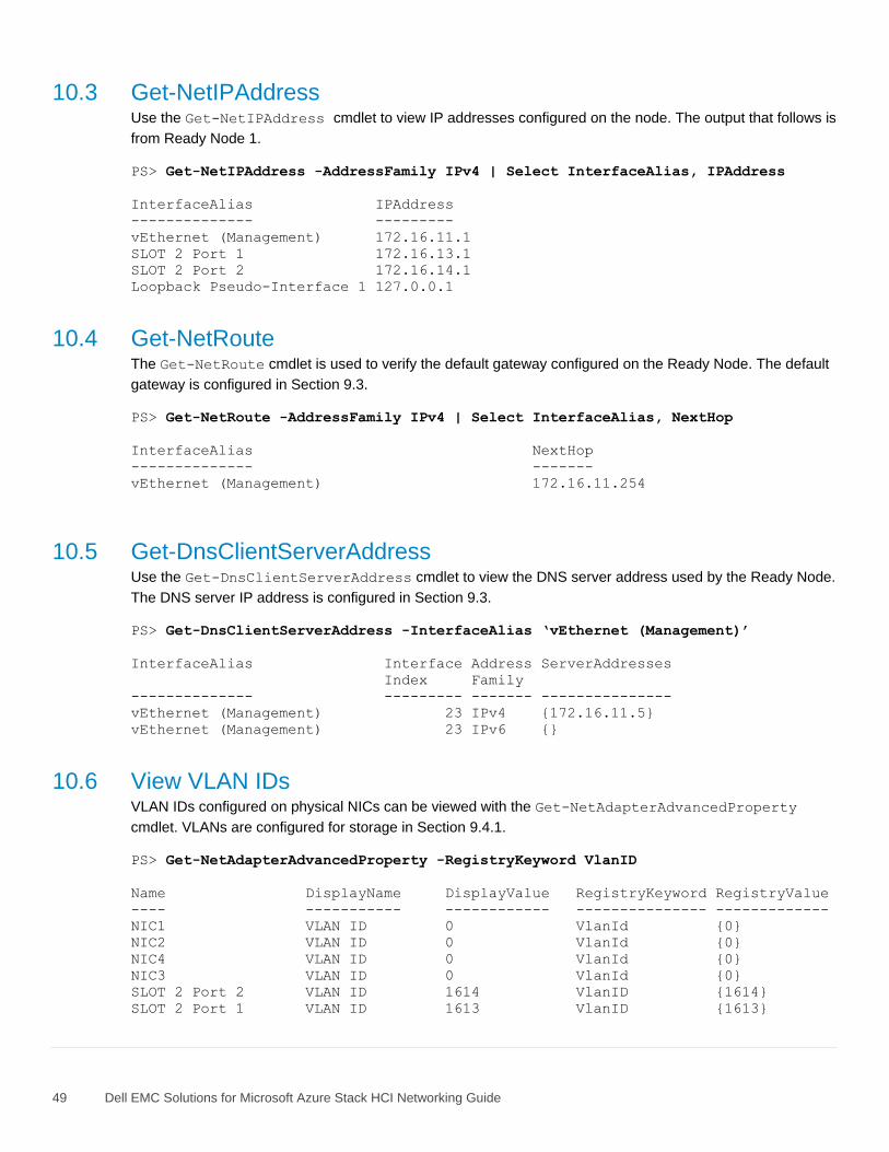
49 Dell EMC Solutions for Microsoft Azure Stack HCI Networking Guide
10.3 Get-NetIPAddress Use the Get-NetIPAddress cmdlet to view IP addresses configured on the node. The output that follows is
from Ready Node 1.
PS> Get-NetIPAddress -AddressFamily IPv4 | Select InterfaceAlias, IPAddress
InterfaceAlias IPAddress
-------------- ---------
vEthernet (Management) 172.16.11.1
SLOT 2 Port 1 172.16.13.1
SLOT 2 Port 2 172.16.14.1
Loopback Pseudo-Interface 1 127.0.0.1
10.4 Get-NetRoute The Get-NetRoute cmdlet is used to verify the default gateway configured on the Ready Node. The default
gateway is configured in Section 9.3.
PS> Get-NetRoute -AddressFamily IPv4 | Select InterfaceAlias, NextHop
InterfaceAlias NextHop
-------------- -------
vEthernet (Management) 172.16.11.254
10.5 Get-DnsClientServerAddress Use the Get-DnsClientServerAddress cmdlet to view the DNS server address used by the Ready Node.
The DNS server IP address is configured in Section 9.3.
PS> Get-DnsClientServerAddress -InterfaceAlias ‘vEthernet (Management)’
InterfaceAlias Interface Address ServerAddresses
Index Family
-------------- --------- ------- ---------------
vEthernet (Management) 23 IPv4 {172.16.11.5}
vEthernet (Management) 23 IPv6 {}
10.6 View VLAN IDs VLAN IDs configured on physical NICs can be viewed with the Get-NetAdapterAdvancedProperty
cmdlet. VLANs are configured for storage in Section 9.4.1.
PS> Get-NetAdapterAdvancedProperty -RegistryKeyword VlanID
Name DisplayName DisplayValue RegistryKeyword RegistryValue
---- ----------- ------------ --------------- -------------
NIC1 VLAN ID 0 VlanId {0}
NIC2 VLAN ID 0 VlanId {0}
NIC4 VLAN ID 0 VlanId {0}
NIC3 VLAN ID 0 VlanId {0}
SLOT 2 Port 2 VLAN ID 1614 VlanID {1614}
SLOT 2 Port 1 VLAN ID 1613 VlanID {1613}
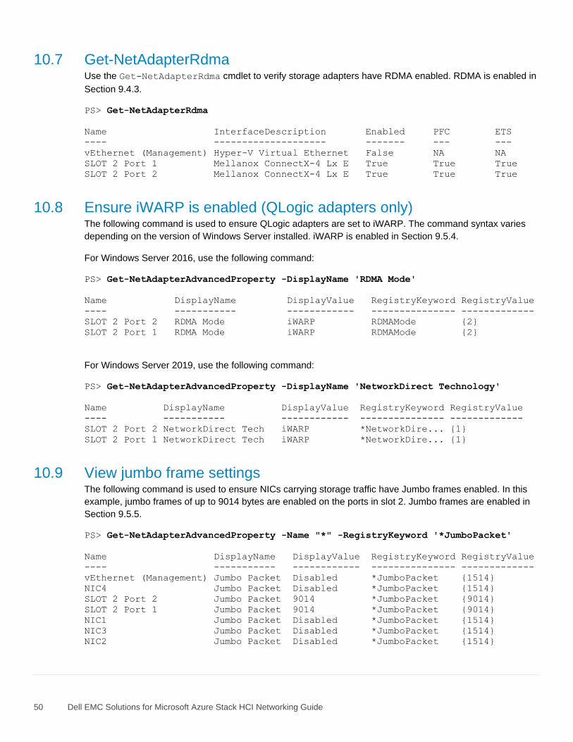
50 Dell EMC Solutions for Microsoft Azure Stack HCI Networking Guide
10.7 Get-NetAdapterRdma Use the Get-NetAdapterRdma cmdlet to verify storage adapters have RDMA enabled. RDMA is enabled in
Section 9.4.3.
PS> Get-NetAdapterRdma
Name InterfaceDescription Enabled PFC ETS
---- -------------------- ------- --- ---
vEthernet (Management) Hyper-V Virtual Ethernet False NA NA
SLOT 2 Port 1 Mellanox ConnectX-4 Lx E True True True
SLOT 2 Port 2 Mellanox ConnectX-4 Lx E True True True
10.8 Ensure iWARP is enabled (QLogic adapters only) The following command is used to ensure QLogic adapters are set to iWARP. The command syntax varies
depending on the version of Windows Server installed. iWARP is enabled in Section 9.5.4.
For Windows Server 2016, use the following command:
PS> Get-NetAdapterAdvancedProperty -DisplayName 'RDMA Mode'
Name DisplayName DisplayValue RegistryKeyword RegistryValue
---- ----------- ------------ --------------- -------------
SLOT 2 Port 2 RDMA Mode iWARP RDMAMode {2}
SLOT 2 Port 1 RDMA Mode iWARP RDMAMode {2}
For Windows Server 2019, use the following command:
PS> Get-NetAdapterAdvancedProperty -DisplayName 'NetworkDirect Technology'
Name DisplayName DisplayValue RegistryKeyword RegistryValue
---- ----------- ------------ --------------- -------------
SLOT 2 Port 2 NetworkDirect Tech iWARP *NetworkDire... {1}
SLOT 2 Port 1 NetworkDirect Tech iWARP *NetworkDire... {1}
10.9 View jumbo frame settings The following command is used to ensure NICs carrying storage traffic have Jumbo frames enabled. In this
example, jumbo frames of up to 9014 bytes are enabled on the ports in slot 2. Jumbo frames are enabled in
Section 9.5.5.
PS> Get-NetAdapterAdvancedProperty -Name "*" -RegistryKeyword '*JumboPacket'
Name DisplayName DisplayValue RegistryKeyword RegistryValue
---- ----------- ------------ --------------- -------------
vEthernet (Management) Jumbo Packet Disabled *JumboPacket {1514}
NIC4 Jumbo Packet Disabled *JumboPacket {1514}
SLOT 2 Port 2 Jumbo Packet 9014 *JumboPacket {9014}
SLOT 2 Port 1 Jumbo Packet 9014 *JumboPacket {9014}
NIC1 Jumbo Packet Disabled *JumboPacket {1514}
NIC3 Jumbo Packet Disabled *JumboPacket {1514}
NIC2 Jumbo Packet Disabled *JumboPacket {1514}
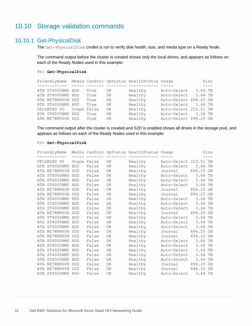
51 Dell EMC Solutions for Microsoft Azure Stack HCI Networking Guide
10.10 Storage validation commands
10.10.1 Get-PhysicalDisk The Get-PhysicalDisk cmdlet is run to verify disk health, size, and media type on a Ready Node.
The command output before the cluster is created shows only the local drives, and appears as follows on
each of the Ready Nodes used in this example:
PS> Get-PhysicalDisk
FriendlyName Media CanPool OpStatus HealthStatus Usage Size
------------ ----- ------- -------- ------------ ----- ----
ATA ST4000NM0 HDD True OK Healthy Auto-Select 3.64 TB
ATA ST4000NM0 HDD True OK Healthy Auto-Select 3.64 TB
ATA MZ7KM960H SSD True OK Healthy Auto-Select 894.25 GB
ATA ST4000NM0 HDD True OK Healthy Auto-Select 3.64 TB
DELLBOSS VD Unspe False OK Healthy Auto-Select 223.51 GB
ATA ST4000NM0 HDD True OK Healthy Auto-Select 3.64 TB
ATA MZ7KM960H SSD True OK Healthy Auto-Select 894.25 GB
The command output after the cluster is created and S2D is enabled shows all drives in the storage pool, and
appears as follows on each of the Ready Nodes used in this example:
PS> Get-PhysicalDisk
FriendlyName Media CanPool OpStatus HealthStatus Usage Size
------------ ----- ------- -------- ------------ ----- ----
DELLBOSS VD Unspe False OK Healthy Auto-Select 223.51 GB
ATA ST4000NM0 HDD False OK Healthy Auto-Select 3.64 TB
ATA MZ7KM960H SSD False OK Healthy Journal 894.25 GB
ATA ST4000NM0 HDD False OK Healthy Auto-Select 3.64 TB
ATA ST4000NM0 HDD False OK Healthy Auto-Select 3.64 TB
ATA ST4000NM0 HDD False OK Healthy Auto-Select 3.64 TB
ATA MZ7KM960H SSD False OK Healthy Journal 894.25 GB
ATA MZ7KM960H SSD False OK Healthy Journal 894.25 GB
ATA ST4000NM0 HDD False OK Healthy Auto-Select 3.64 TB
ATA ST4000NM0 HDD False OK Healthy Auto-Select 3.64 TB
ATA ST4000NM0 HDD False OK Healthy Auto-Select 3.64 TB
ATA MZ7KM960H SSD False OK Healthy Journal 894.25 GB
ATA ST4000NM0 HDD False OK Healthy Auto-Select 3.64 TB
ATA ST4000NM0 HDD False OK Healthy Auto-Select 3.64 TB
ATA ST4000NM0 HDD False OK Healthy Auto-Select 3.64 TB
ATA MZ7KM960H SSD False OK Healthy Journal 894.25 GB
ATA MZ7KM960H SSD False OK Healthy Journal 894.25 GB
ATA ST4000NM0 HDD False OK Healthy Auto-Select 3.64 TB
ATA ST4000NM0 HDD False OK Healthy Auto-Select 3.64 TB
ATA ST4000NM0 HDD False OK Healthy Auto-Select 3.64 TB
ATA ST4000NM0 HDD False OK Healthy Auto-Select 3.64 TB
ATA ST4000NM0 HDD False OK Healthy Auto-Select 3.64 TB
ATA MZ7KM960H SSD False OK Healthy Journal 894.25 GB
ATA MZ7KM960H SSD False OK Healthy Journal 894.25 GB
ATA ST4000NM0 HDD False OK Healthy Auto-Select 3.64 TB
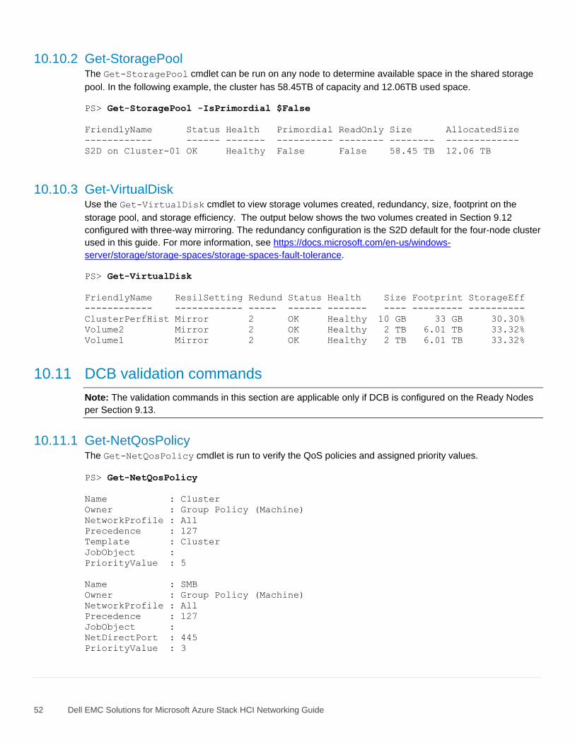
52 Dell EMC Solutions for Microsoft Azure Stack HCI Networking Guide
10.10.2 Get-StoragePool The Get-StoragePool cmdlet can be run on any node to determine available space in the shared storage
pool. In the following example, the cluster has 58.45TB of capacity and 12.06TB used space.
PS> Get-StoragePool -IsPrimordial $False
FriendlyName Status Health Primordial ReadOnly Size AllocatedSize
------------ ------ ------- ---------- -------- -------- -------------
S2D on Cluster-01 OK Healthy False False 58.45 TB 12.06 TB
10.10.3 Get-VirtualDisk Use the Get-VirtualDisk cmdlet to view storage volumes created, redundancy, size, footprint on the
storage pool, and storage efficiency. The output below shows the two volumes created in Section 9.12
configured with three-way mirroring. The redundancy configuration is the S2D default for the four-node cluster
used in this guide. For more information, see https://docs.microsoft.com/en-us/windows-
server/storage/storage-spaces/storage-spaces-fault-tolerance.
PS> Get-VirtualDisk
FriendlyName ResilSetting Redund Status Health Size Footprint StorageEff
------------ ------------ ----- ------ ------- ---- --------- ----------
ClusterPerfHist Mirror 2 OK Healthy 10 GB 33 GB 30.30%
Volume2 Mirror 2 OK Healthy 2 TB 6.01 TB 33.32%
Volume1 Mirror 2 OK Healthy 2 TB 6.01 TB 33.32%
10.11 DCB validation commands
Note: The validation commands in this section are applicable only if DCB is configured on the Ready Nodes
per Section 9.13.
10.11.1 Get-NetQosPolicy The Get-NetQosPolicy cmdlet is run to verify the QoS policies and assigned priority values.
PS> Get-NetQosPolicy
Name : Cluster
Owner : Group Policy (Machine)
NetworkProfile : All
Precedence : 127
Template : Cluster
JobObject :
PriorityValue : 5
Name : SMB
Owner : Group Policy (Machine)
NetworkProfile : All
Precedence : 127
JobObject :
NetDirectPort : 445
PriorityValue : 3
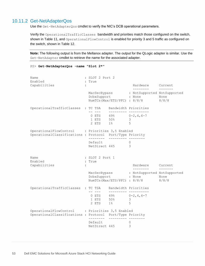
53 Dell EMC Solutions for Microsoft Azure Stack HCI Networking Guide
10.11.2 Get-NetAdapterQos Use the Get-NetAdapterQos cmdlet to verify the NIC’s DCB operational parameters.
Verify the OperationalTrafficClasses bandwidth and priorities match those configured on the switch,
shown in Table 11, and OperationalFlowControl is enabled for priority 3 and 5 traffic as configured on
the switch, shown in Table 12.
Note: The following output is from the Mellanox adapter. The output for the QLogic adapter is similar. Use the
Get-NetAdapter cmdlet to retrieve the name for the associated adapter.
PS> Get-NetAdapterQos -name "Slot 2*"
Name : SLOT 2 Port 2
Enabled : True
Capabilities : Hardware Current
-------- -------
MacSecBypass : NotSupported NotSupported
DcbxSupport : None None
NumTCs(Max/ETS/PFC) : 8/8/8 8/8/8
OperationalTrafficClasses : TC TSA Bandwidth Priorities
-- --- --------- ----------
0 ETS 49% 0-2,4,6-7
1 ETS 50% 3
2 ETS 1% 5
OperationalFlowControl : Priorities 3,5 Enabled
OperationalClassifications : Protocol Port/Type Priority
-------- --------- --------
Default 0
NetDirect 445 3
Name : SLOT 2 Port 1
Enabled : True
Capabilities : Hardware Current
-------- -------
MacSecBypass : NotSupported NotSupported
DcbxSupport : None None
NumTCs(Max/ETS/PFC) : 8/8/8 8/8/8
OperationalTrafficClasses : TC TSA Bandwidth Priorities
-- --- --------- ----------
0 ETS 49% 0-2,4,6-7
1 ETS 50% 3
2 ETS 1% 5
OperationalFlowControl : Priorities 3,5 Enabled
OperationalClassifications : Protocol Port/Type Priority
-------- --------- --------
Default 0
NetDirect 445 3
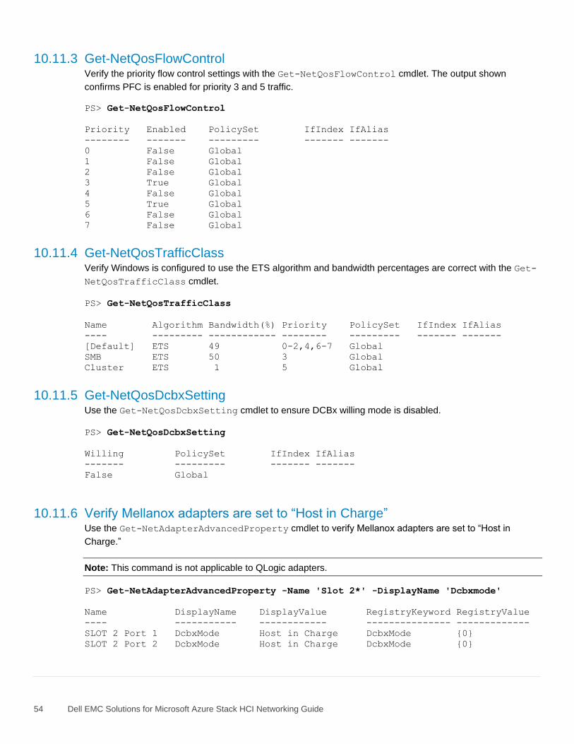
54 Dell EMC Solutions for Microsoft Azure Stack HCI Networking Guide
10.11.3 Get-NetQosFlowControl Verify the priority flow control settings with the Get-NetQosFlowControl cmdlet. The output shown
confirms PFC is enabled for priority 3 and 5 traffic.
PS> Get-NetQosFlowControl
Priority Enabled PolicySet IfIndex IfAlias
-------- ------- --------- ------- -------
0 False Global
1 False Global
2 False Global
3 True Global
4 False Global
5 True Global
6 False Global
7 False Global
10.11.4 Get-NetQosTrafficClass Verify Windows is configured to use the ETS algorithm and bandwidth percentages are correct with the Get-
NetQosTrafficClass cmdlet.
PS> Get-NetQosTrafficClass
Name Algorithm Bandwidth(%) Priority PolicySet IfIndex IfAlias
---- --------- ------------ -------- --------- ------- -------
[Default] ETS 49 0-2,4,6-7 Global
SMB ETS 50 3 Global
Cluster ETS 1 5 Global
10.11.5 Get-NetQosDcbxSetting Use the Get-NetQosDcbxSetting cmdlet to ensure DCBx willing mode is disabled.
PS> Get-NetQosDcbxSetting
Willing PolicySet IfIndex IfAlias
------- --------- ------- -------
False Global
10.11.6 Verify Mellanox adapters are set to “Host in Charge” Use the Get-NetAdapterAdvancedProperty cmdlet to verify Mellanox adapters are set to “Host in
Charge.”
Note: This command is not applicable to QLogic adapters.
PS> Get-NetAdapterAdvancedProperty -Name 'Slot 2*' -DisplayName 'Dcbxmode'
Name DisplayName DisplayValue RegistryKeyword RegistryValue
---- ----------- ------------ --------------- -------------
SLOT 2 Port 1 DcbxMode Host in Charge DcbxMode {0}
SLOT 2 Port 2 DcbxMode Host in Charge DcbxMode {0}
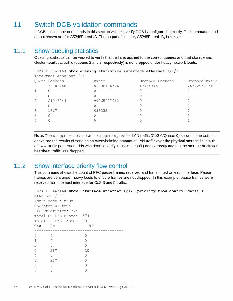
55 Dell EMC Solutions for Microsoft Azure Stack HCI Networking Guide
11 Switch DCB validation commands If DCB is used, the commands in this section will help verify DCB is configured correctly. The commands and
output shown are for S5248F-Leaf1A. The output of its peer, S5248F-Leaf1B, is similar.
11.1 Show queuing statistics Queuing statistics can be viewed to verify that traffic is applied to the correct queues and that storage and
cluster heartbeat traffic (queues 3 and 5 respectively) is not dropped under heavy network loads.
S5248F-Leaf1A# show queuing statistics interface ethernet 1/1/1
Interface ethernet1/1/1
Queue Packets Bytes Dropped-Packets Dropped-Bytes
0 32082748 89906196746 17774345 26742951754
1 0 0 0 0
2 0 0 0 0
3 21947244 90065497612 0 0
4 0 0 0 0
5 1567 655233 0 0
6 0 0 0 0
7 0 0 0 0
Note: The Dropped-Packets and Dropped-Bytes for LAN traffic (CoS 0/Queue 0) shown in the output
above are the results of sending an overwhelming amount of LAN traffic over the physical storage links with
an IXIA traffic generator. This was done to verify DCB was configured correctly and that no storage or cluster
heartbeat traffic was dropped.
11.2 Show interface priority flow control This command shows the count of PFC pause frames received and transmitted on each interface. Pause
frames are sent under heavy loads to ensure frames are not dropped. In this example, pause frames were
received from the host interface for CoS 3 and 5 traffic.
S5248F-Leaf1A# show interface ethernet 1/1/1 priority-flow-control details
ethernet1/1/1
Admin Mode : true
Operstatus: true
PFC Priorities: 3,5
Total Rx PFC Frames: 574
Total Tx PFC frames: 20
Cos Rx Tx
---------------------------------------
0 0 0
1 0 0
2 0 0
3 287 20
4 0 0
5 287 0
6 0 0
7 0 0

56 Dell EMC Solutions for Microsoft Azure Stack HCI Networking Guide
A Validated components
The following tables include the hardware, software, and firmware used to configure and validate the
examples in this guide.
A.1 Dell EMC Networking Switches
Switches and OS versions
Qty Item OS Version
2 Dell EMC Networking S5248F-ON leaf switch 10.4.2.2
1 Dell EMC Networking S3048-ON management switch 10.4.2.2
Note: See Table 1 for supported Dell EMC Networking switches and OS versions.
A.2 S2D Ready Nodes
Note: For the current list of supported firmware and driver versions, see the Support Matrix for Dell EMC
Solutions for Microsoft Azure Stack HCI.
A cluster of four PowerEdge R740xd S2D Ready Nodes was used to validate the examples in this guide. The
nodes were each configured as shown in Table 15 for Windows Server 2016 and Table 16 for Windows
Server 2019.
PowerEdge R740xd S2D Ready Node components with WS2016
Qty per node
Item Firmware Driver
2 Intel Xeon Gold 6148 CPU @ 2.40GHz, 20 cores - -
12 16GB DDR4 DIMM (192GB total) - -
2 960GB SATA SSD - -
4 4TB SATA HDD - -
1 Dell HBA330 Storage Controller 15.17.09.06 2.51.21.2
1 Boot Optimized Storage Solution (BOSS) S1 Controller w/ 2x240GB SATA M.2 SSD
2.5.13.3011 1.2.0.1048
1 QLogic FastLinQ QL41262HxCU-DE 2x25GbE SFP28 14.07.07 8.24.5.0
1 Mellanox ConnectX-4 Lx 2x25GbE SFP28 14.21.30.12 2.0.19824.0
1 Intel X710 2x10GbE SFP+/I350 2x1000BASE-T rNDC 18.5.17 1.8.104.5
- BIOS 1.5.6 -
- iDRAC with Lifecycle Controller 3.21.23.22 -
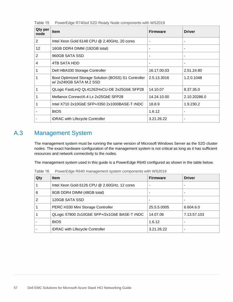
57 Dell EMC Solutions for Microsoft Azure Stack HCI Networking Guide
PowerEdge R740xd S2D Ready Node components with WS2019
Qty per node
Item Firmware Driver
2 Intel Xeon Gold 6148 CPU @ 2.40GHz, 20 cores - -
12 16GB DDR4 DIMM (192GB total) - -
2 960GB SATA SSD - -
4 4TB SATA HDD - -
1 Dell HBA330 Storage Controller 16.17.00.03 2.51.24.80
1 Boot Optimized Storage Solution (BOSS) S1 Controller w/ 2x240GB SATA M.2 SSD
2.5.13.3016 1.2.0.1048
1 QLogic FastLinQ QL41262HxCU-DE 2x25GbE SFP28 14.10.07 8.37.35.0
1 Mellanox ConnectX-4 Lx 2x25GbE SFP28 14.24.10.00 2.10.20286.0
1 Intel X710 2x10GbE SFP+/I350 2x1000BASE-T rNDC 18.8.9 1.9.230.2
- BIOS 1.6.12 -
- iDRAC with Lifecycle Controller 3.21.26.22 -
A.3 Management System
The management system must be running the same version of Microsoft Windows Server as the S2D cluster
nodes. The exact hardware configuration of the management system is not critical as long as it has sufficient
resources and network connectivity to the nodes.
The management system used in this guide is a PowerEdge R640 configured as shown in the table below.
PowerEdge R640 management system components with WS2019
Qty Item Firmware Driver
1 Intel Xeon Gold 6126 CPU @ 2.60GHz, 12 cores - -
6 8GB DDR4 DIMM (48GB total) - -
2 120GB SATA SSD - -
1 PERC H330 Mini Storage Controller 25.5.5.0005 6.604.6.0
1 QLogic 57800 2x10GbE SFP+/2x1GbE BASE-T rNDC 14.07.06 7.13.57.103
- BIOS 1.6.12 -
- iDRAC with Lifecycle Controller 3.21.26.22 -
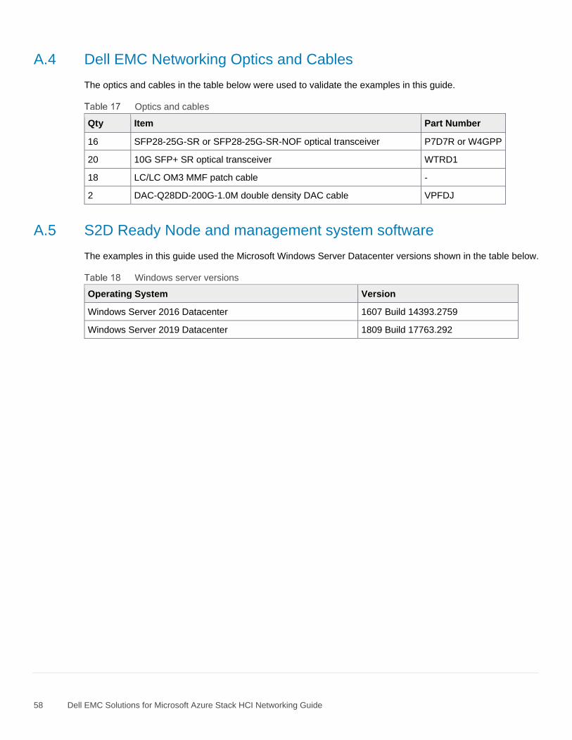
58 Dell EMC Solutions for Microsoft Azure Stack HCI Networking Guide
A.4 Dell EMC Networking Optics and Cables
The optics and cables in the table below were used to validate the examples in this guide.
Optics and cables
Qty Item Part Number
16 SFP28-25G-SR or SFP28-25G-SR-NOF optical transceiver P7D7R or W4GPP
20 10G SFP+ SR optical transceiver WTRD1
18 LC/LC OM3 MMF patch cable -
2 DAC-Q28DD-200G-1.0M double density DAC cable VPFDJ
A.5 S2D Ready Node and management system software
The examples in this guide used the Microsoft Windows Server Datacenter versions shown in the table below.
Windows server versions
Operating System Version
Windows Server 2016 Datacenter 1607 Build 14393.2759
Windows Server 2019 Datacenter 1809 Build 17763.292
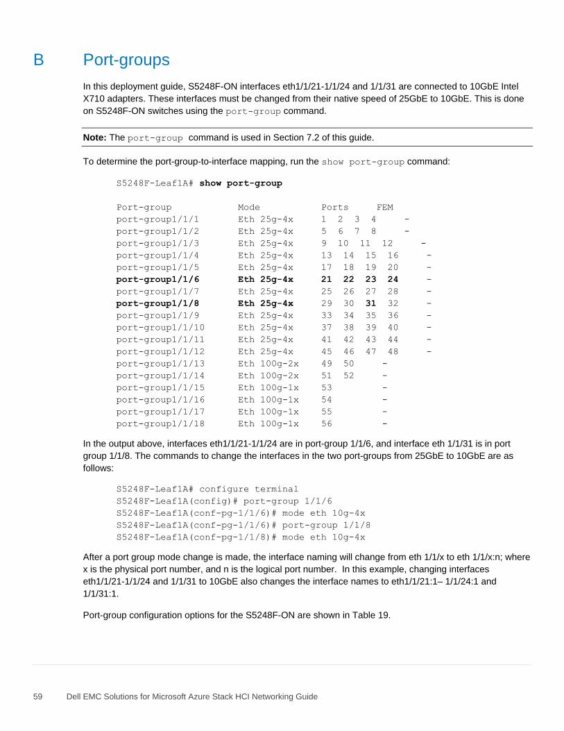
59 Dell EMC Solutions for Microsoft Azure Stack HCI Networking Guide
B Port-groups
In this deployment guide, S5248F-ON interfaces eth1/1/21-1/1/24 and 1/1/31 are connected to 10GbE Intel
X710 adapters. These interfaces must be changed from their native speed of 25GbE to 10GbE. This is done
on S5248F-ON switches using the port-group command.
Note: The port-group command is used in Section 7.2 of this guide.
To determine the port-group-to-interface mapping, run the show port-group command:
S5248F-Leaf1A# show port-group
Port-group Mode Ports FEM
port-group1/1/1 Eth 25g-4x 1 2 3 4 -
port-group1/1/2 Eth 25g-4x 5 6 7 8 -
port-group1/1/3 Eth 25g-4x 9 10 11 12 -
port-group1/1/4 Eth 25g-4x 13 14 15 16 -
port-group1/1/5 Eth 25g-4x 17 18 19 20 -
port-group1/1/6 Eth 25g-4x 21 22 23 24 -
port-group1/1/7 Eth 25g-4x 25 26 27 28 -
port-group1/1/8 Eth 25g-4x 29 30 31 32 -
port-group1/1/9 Eth 25g-4x 33 34 35 36 -
port-group1/1/10 Eth 25g-4x 37 38 39 40 -
port-group1/1/11 Eth 25g-4x 41 42 43 44 -
port-group1/1/12 Eth 25g-4x 45 46 47 48 -
port-group1/1/13 Eth 100g-2x 49 50 -
port-group1/1/14 Eth 100g-2x 51 52 -
port-group1/1/15 Eth 100g-1x 53 -
port-group1/1/16 Eth 100g-1x 54 -
port-group1/1/17 Eth 100g-1x 55 -
port-group1/1/18 Eth 100g-1x 56 -
In the output above, interfaces eth1/1/21-1/1/24 are in port-group 1/1/6, and interface eth 1/1/31 is in port
group 1/1/8. The commands to change the interfaces in the two port-groups from 25GbE to 10GbE are as
follows:
S5248F-Leaf1A# configure terminal
S5248F-Leaf1A(config)# port-group 1/1/6
S5248F-Leaf1A(conf-pg-1/1/6)# mode eth 10g-4x
S5248F-Leaf1A(conf-pg-1/1/6)# port-group 1/1/8
S5248F-Leaf1A(conf-pg-1/1/8)# mode eth 10g-4x
After a port group mode change is made, the interface naming will change from eth 1/1/x to eth 1/1/x:n; where
x is the physical port number, and n is the logical port number. In this example, changing interfaces
eth1/1/21-1/1/24 and 1/1/31 to 10GbE also changes the interface names to eth1/1/21:1– 1/1/24:1 and
1/1/31:1.
Port-group configuration options for the S5248F-ON are shown in Table 19.
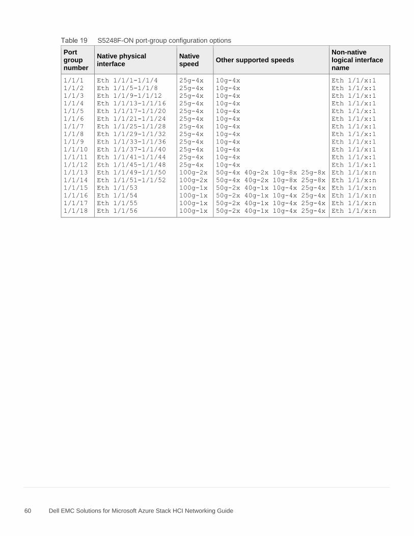
60 Dell EMC Solutions for Microsoft Azure Stack HCI Networking Guide
S5248F-ON port-group configuration options
Port group number
Native physical interface
Native speed
Other supported speeds Non-native logical interface name
1/1/1
1/1/2
1/1/3
1/1/4
1/1/5
1/1/6
1/1/7
1/1/8
1/1/9
1/1/10
1/1/11
1/1/12
1/1/13
1/1/14
1/1/15
1/1/16
1/1/17
1/1/18
Eth 1/1/1-1/1/4
Eth 1/1/5-1/1/8
Eth 1/1/9-1/1/12
Eth 1/1/13-1/1/16
Eth 1/1/17-1/1/20
Eth 1/1/21-1/1/24
Eth 1/1/25-1/1/28
Eth 1/1/29-1/1/32
Eth 1/1/33-1/1/36
Eth 1/1/37-1/1/40
Eth 1/1/41-1/1/44
Eth 1/1/45-1/1/48
Eth 1/1/49-1/1/50
Eth 1/1/51-1/1/52
Eth 1/1/53
Eth 1/1/54
Eth 1/1/55
Eth 1/1/56
25g-4x
25g-4x
25g-4x
25g-4x
25g-4x
25g-4x
25g-4x
25g-4x
25g-4x
25g-4x
25g-4x
25g-4x
100g-2x
100g-2x
100g-1x
100g-1x
100g-1x
100g-1x
10g-4x
10g-4x
10g-4x
10g-4x
10g-4x
10g-4x
10g-4x
10g-4x
10g-4x
10g-4x
10g-4x
10g-4x
50g-4x 40g-2x 10g-8x 25g-8x
50g-4x 40g-2x 10g-8x 25g-8x
50g-2x 40g-1x 10g-4x 25g-4x
50g-2x 40g-1x 10g-4x 25g-4x
50g-2x 40g-1x 10g-4x 25g-4x
50g-2x 40g-1x 10g-4x 25g-4x
Eth 1/1/x:1
Eth 1/1/x:1
Eth 1/1/x:1
Eth 1/1/x:1
Eth 1/1/x:1
Eth 1/1/x:1
Eth 1/1/x:1
Eth 1/1/x:1
Eth 1/1/x:1
Eth 1/1/x:1
Eth 1/1/x:1
Eth 1/1/x:1
Eth 1/1/x:n
Eth 1/1/x:n
Eth 1/1/x:n
Eth 1/1/x:n
Eth 1/1/x:n
Eth 1/1/x:n
61 Dell EMC Solutions for Microsoft Azure Stack HCI Networking Guide
C Technical resources
Dell EMC Networking Guides
OS10 Enterprise Edition User Guide Release 10.4.2.0
Manuals and documentation for Dell EMC Networking S3048-ON
Manuals and documentation for Dell EMC Networking S5248F-ON
Dell EMC Solutions for Microsoft Azure Stack HCI page
Dell EMC Solutions for Microsoft Azure Stack HCI Deployment Guide
Support Matrix for Dell EMC Solutions for Microsoft Azure Stack HCI
Dell EMC Networking Layer 3 Leaf-Spine Deployment and Best Practices with OS10EE
Dell EMC Networking OS10 Enterprise Edition Quick Start Guide
Microsoft Storage Spaces Direct documentation
Microsoft Windows Server 2016 and 2019 RDMA Deployment Guide
62 Dell EMC Solutions for Microsoft Azure Stack HCI Networking Guide
D Fabric Design Center
The Dell EMC Fabric Design Center (FDC) is a cloud-based application that automates the planning, design,
and deployment of network fabrics that power Dell EMC compute, storage and hyper-converged infrastructure
solutions. The FDC is ideal for turnkey solutions and automation based on validated deployment guides.
FDC allows design customization and flexibility to go beyond validated deployment guides. For additional
information, visit the Dell EMC Fabric Design Center.
63 Dell EMC Solutions for Microsoft Azure Stack HCI Networking Guide
E Support and feedback
Contacting Technical Support
Support Contact Information Web: http://www.dell.com/support
Telephone: USA: 1-800-945-3355
Feedback for this document
We encourage readers to provide feedback on the quality and usefulness of this publication by sending an
email to [email protected].