delta 3000 - netech corporation · this manual is provided to explain the operation of the delta...
TRANSCRIPT
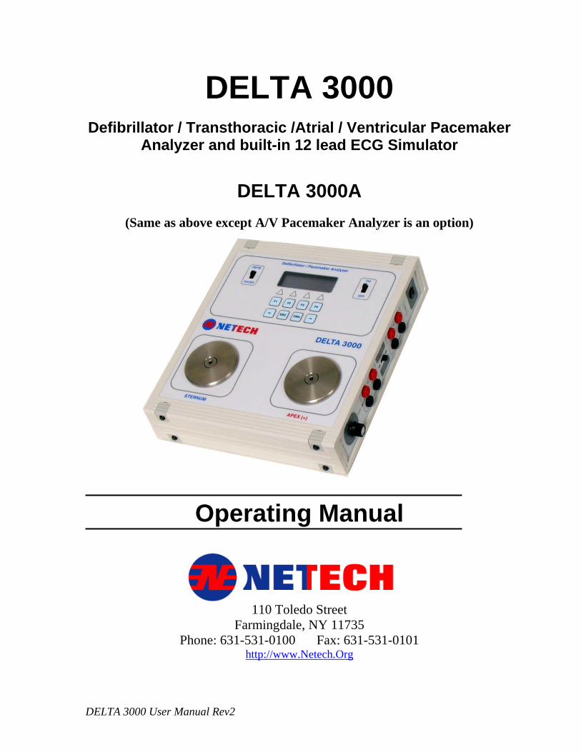
DELTA 3000 Defibrillator / Transthoracic /Atrial / Ventricular Pacemaker
Analyzer and built-in 12 lead ECG Simulator
DELTA 3000A
(Same as above except A/V Pacemaker Analyzer is an option)
Operating Manual
110 Toledo Street
Farmingdale, NY 11735 Phone: 631-531-0100 Fax: 631-531-0101
http://www.Netech.Org
DELTA 3000 User Manual Rev2
Copyright Copyright © 2002 by Netech Corporation. All rights reserved. No part of this publication may be reproduced or transmitted in any form other than for the purchaser’s personal use without written permission from Netech Corporation. Quality Assurance Netech is ISO 9001-2000 Certified. This instrument was thoroughly tested and inspected according to Netech’s ISO 9001-2000 quality standards and test procedures and found to meet those specifications when it was shipped from the factory.
Warranty Netech warrants the DELTA 3000 against defects in materials and workmanship for one year from the date of original purchase. The standard warranty is extended for a second year if the instrument is returned to Netech for its recommended yearly recalibration. During the warranty period, we will repair or, at our option, replace at no charge a product that proves to be defective, provided you return the product shipping prepaid to Netech Corporation. This warranty does not apply if the product has been damaged by accident or misuse or as the result of service or modification by other than Netech Corporation, or if its serial number is defaced or removed. Netech reserves the right to discontinue the DELTA 3000 at any time, and change its specifications, price, or design without notice and without incurring any obligation. Netech guarantees availability of service parts for 5 years after the manufacture of the unit is discontinued. The warranty is void if you elect to have the unit serviced and / or calibrated by someone other than Netech. The purchaser assumes all liability for any damages or bodily injury which may result from the use or misuse of the unit by the purchaser, his employees, agents, or customers. In no event shall Netech Corporation be liable for consequential damages
Trademarks Netech and DELTA 3000 are trademarks of Netech Corporation. Any other trademark names used in this manual are only for editorial purposes and the benefit of the respective trademark owner with no intention of improperly using that trademark.
DELTA 3000_User_Manual_R2.doc 2
Table of Contents
1. General Overview
1.1 Introduction ------------------------------------------ 06 1.2 Safety Considerations ------------------------------------ 07 1.3 Specifications ------------------------------------------ 08 1.4 Accessories ------------------------------------------ 10
2. Operating Instructions
2.1 Getting Started ------------------------------------------ 11 2.2 Instrument Familiarity ----------------------------------- 12 2.3 Power Up and Initialization ---------------------------- 13 2.4 Menu Structure -------------------------------------------- 13 2.5 Testing a Defibrillator ------------------------------------ 16
2.5.1 Energy Measurement ---------------------------- 16 2.5.2 Peak Voltage and Current ----------------------- 17 2.5.3 Viewing Waveform Output ---------------------- 17 2.5.4 Measuring Cardioversion (Sync.) Time ------ 17
2.6 Testing Semi / Auto Defibrillator ---------------------- 18 2.6.1 Selecting Waveforms ---------------------------- 18 2.6.2 Measuring Energy -------------------------------- 19
2.7 Printing Defibrillator Measurement Data ------------- 19 2.8 ECG Arrhythmia Simulator ---------------------------- 21
2.8.1 Generating Normal Sinus Rhythm Waveform 21 2.8.2 Generating Arrhythmia Waveforms ------------ 22
2.8.3 Arrhythmia Waveform Definitions ------------- 22 2.8.4 Amplitude Selection ------------------------------- 22
2.8.5 Generating Performance Waveforms ----------- 23 2.9 Testing Transthorasic Pacers --------------------------- 24
2.9.1 Selecting Pacer Manufacturer ------------------- 24 2.9.2 Selecting 50 Ohm Test Load ------------------- 25 2.9.3 Selecting Variable Test Loads ------------------ 25 2.9.4 Measuring Pulse Parameters -------------------- 25 2.9.5 Measuring Refractory Periods ----------------- 26 2.9.6 Demand Sensitivity Tests ------------------------ 27 2.9.7 Immunity Tests ----------------------------------- 28 2.9.8 Measuring Energy -------------------------------- 28
2.10 Testing External Transvenous Pacers (AV) ---------- 29 2.10.1 Measuring Pulse Parameters ------------------- 29
DELTA 3000_User_Manual_R2.doc 3
2.10.2 Measuring Refractory Periods ---------------- 29 2.10.3 Demand Sensitivity Tests ---------------------- 30 2.10.4 Immunity Tests ----------------------------------- 31 2.10.5 Measuring AV Interval ------------------------ 32 2.10.6 Measuring Energy ------------------------------ 32 2.10.7 Pacemaker Type Selection --------------------- 32
2.11 Printing Pacer Measurements -------------------------- 33 2.11.1 Printing Without a Header --------------------- 33 2.11.2 Printing With a Header ------------------------- 33
2.12 Automatic Pacer Testing --------------------------------- 34 2.13 Printer Functions ----------------------------------------- 34 2.14 Auxiliary Functions -------------------------------------- 36
2.14.1 AV Pacer Test Function ----------------------- 36 2.14.2 Transcutaneous Pacer Test Function -------- 37 2.14.3 Calibration Check ------------------------------ 37 2.14.4 Printer Format Selection ---------------------- 38 2.14.5 Pacemaker Battery Current Test ------------- 39
3. Serial Port Interface
3.1 Introduction ------------------------------------------ 39 3.2 Netech PalmSoft Set Up Procedure -------------- 39 3.3 Receiving and Saving Data ----------------------- 40
4. Theory of Operation
4.1 Introduction ---------------------------------------- 41 4.2 Defibrillator Output Measurement ------------ 41 4.3 Pacemaker Output Measurement ------------ 41 4.4 Circuit Block Descriptions ----------------------- 42
5. Troubleshooting DELTA 3000 --------------------------- 45
6. Appendix ------------------------------------------------------- 46
DELTA 3000_User_Manual_R2.doc 4
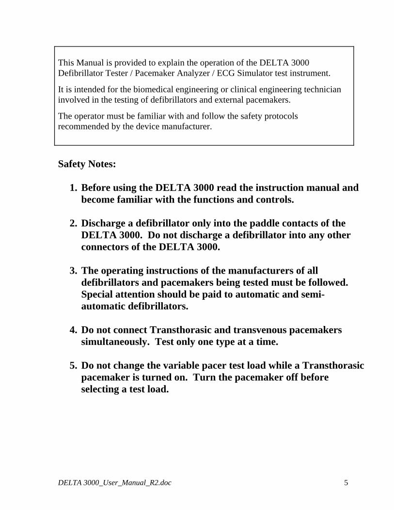
This Manual is provided to explain the operation of the DELTA 3000 Defibrillator Tester / Pacemaker Analyzer / ECG Simulator test instrument.
It is intended for the biomedical engineering or clinical engineering technician involved in the testing of defibrillators and external pacemakers.
The operator must be familiar with and follow the safety protocols recommended by the device manufacturer.
Safety Notes:
1. Before using the DELTA 3000 read the instruction manual and become familiar with the functions and controls.
2. Discharge a defibrillator only into the paddle contacts of the
DELTA 3000. Do not discharge a defibrillator into any other connectors of the DELTA 3000.
3. The operating instructions of the manufacturers of all
defibrillators and pacemakers being tested must be followed. Special attention should be paid to automatic and semi-automatic defibrillators.
4. Do not connect Transthorasic and transvenous pacemakers
simultaneously. Test only one type at a time.
5. Do not change the variable pacer test load while a Transthorasic pacemaker is turned on. Turn the pacemaker off before selecting a test load.
DELTA 3000_User_Manual_R2.doc 5
GENERAL OVERVIEW Section 1
1.1 Introduction
The DELTA 3000 is a biomedical test instrument that combines the complete testing functions of a defibrillator tester, a pacemaker analyzer, and a 12 lead ECG / Arrhythmia simulator into one compact instrument.
The Delta 3000 is designed to accurately measure the output parameters of defibrillators and external pacemakers, including both Transthorasic and transcutaneous devices. It simulates a wide variety of arrhythmia waveforms for testing automatic defibrillators and ECG equipment.
It is compact, lightweight, and rugged. The Delta 3000 is operated via easy to use menus displayed on its large display. It may be battery or AC operated.
1.1.1 Defibrillator Test Functions
The Delta 3000 measures the delivered energy of a defibrillator in Joules (watt – seconds). The built in test load (50 Ohms) simulates the human body’s resistance. The energy is measured in two ranges: 0-100 Joules (LOW) or 0 – 1000 Joules (HI). The Peak Voltage and Current are displayed simultaneously.
The cardioversion delay time of a defibrillator in its synchronized mode is measured in milliseconds from the R wave peak of the simulated ECG waveform.
The defibrillator pulse waveform can be replayed via the ECG jacks on the side panel or through the paddles to print on a recorder or view on an oscilloscope.
1.1.2 Pacemaker Test Functions
The Delta 3000 makes several measurements of Transthorasic and transvenous (A-V) pacemakers.
1.1.2.1 Transthorasic Pacers
Test load: 50 Ohms or user selectable load from 100 to 1000 Ohms.
Measures: Peak current, pulse width, pulse rate, paced refractory period, sensed refractory period, and pulse energy.
1.1.2.2 Transvenous Pacers (This feature is available only in Full version)*
DELTA 3000_User_Manual_R2.doc 6
Measures: Peak current, pulse width, pulse rate, paced refractory period, sensed refractory period, immunity test (50Hz/60 Hz), A/ V interval, and pulse energy.
Measures the current drain (ON / OFF) of the pacemaker, using the optional adapter (PN xxxxx).
1.1.3 ECG / Arrhythmia Simulator Functions
The Delta 3000 simulates a normal sinus rhythm ECG waveform along with several arrhythmias. It also generates sine, square, triangle, and pulse performance waveforms.
1.2 Safety Considerations
Before using the DELTA 3000, the operator must follow the safety precautions listed in this manual.
1.2.1 Defibrillators
Defibrillators deliver high voltage shocks to a patient in order to stop a heart attack. The defibrillator discharge pulse is potentially dangerous.
1.2.2 Automatic Defibrillators
Automatic defibrillators discharge automatically when they detect a life threatening heart condition, which requires a shock.
The DELTA 3000 simulates a vide variety of arrhythmia waveforms. When the instrument is connected to an automatic defibrillator and a ventricular fibrillation (VFB) or ventricular tachycardia waveform is selected, the defibrillator will discharge. The fully automatic defibrillator will warn the user that it is about to discharge. Always heed the audible warnings of the defibrillator. Use the recommended paddle adapters for connecting to the DELTA 3000. Do not touch the paddle or electrode contacts.
DELTA 3000_User_Manual_R2.doc 7
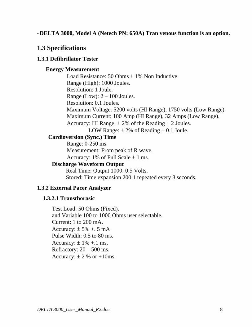
* DELTA 3000, Model A (Netech PN: 650A) Tran venous function is an option.
1.3 Specifications
1.3.1 Defibrillator Tester
Energy Measurement Load Resistance: 50 Ohms ± 1% Non Inductive. Range (High): 1000 Joules. Resolution: 1 Joule. Range (Low): 2 – 100 Joules. Resolution: 0.1 Joules.
Maximum Voltage: 5200 volts (HI Range), 1750 volts (Low Range). Maximum Current: 100 Amp (HI Range), 32 Amps (Low Range). Accuracy: HI Range: ± 2% of the Reading ± 2 Joules. LOW Range: ± 2% of Reading ± 0.1 Joule.
Cardioversion (Sync.) Time Range: 0-250 ms. Measurement: From peak of R wave. Accuracy: 1% of Full Scale ± 1 ms.
Discharge Waveform Output Real Time: Output 1000: 0.5 Volts. Stored: Time expansion 200:1 repeated every 8 seconds.
1.3.2 External Pacer Analyzer
1.3.2.1 Transthorasic
Test Load: 50 Ohms (Fixed). and Variable 100 to 1000 Ohms user selectable. Current: 1 to 200 mA. Accuracy: ± 5% +. 5 mA Pulse Width: 0.5 to 80 ms. Accuracy: ± 1% +.1 ms. Refractory: 20 – 500 ms.
Accuracy: ± 2 % or +10ms.
DELTA 3000_User_Manual_R2.doc 8
1.3.2.2 Transvenous (Atrial and Ventricular) (Option in DELAT 3000A)
Test Load: 500 Ohms ± 1%. Current: 1 to 25 mA. Accuracy: ± 5% +. 5 mA. Pulse Rate: 30 to 800 ppm. Pulse Width: 0.5 to 80 ms. Accuracy: ± 1% +.1 ms. Refractory: 20 – 500 ms. Accuracy: ± 2 % or +10ms. Immunity Test: 50/60 Hz.
1.3.3 ECG Arrhythmia Simulator
ECG Waveform: Normal Sinus Rhythm Rates: 30, 60, 80, 120, 180, 240, 300 BPM
Performance Waveforms: Sine, Square, Triangle, and Pulse Rates: 0.5, 1, 2, 10, 15, 20, 25, 40 Hz.
Arrhythmia Waveforms: VFBC, VFBF, VTAC, AFIB, PVC, PVC1, PVC2, BGY, RBB, AFIB, AFT, PVCM. Amplitudes: 0.5, 1, 1.5, 2, 2.5, 3 mv.
Waveform Output: Low Level: 12 Lead ECG and Paddle Hi Level: Output Jacks
Accuracy: Rate: ± 1 % Amplitude: ± 2% (LA-LL), ± 10% (Paddles)
1.3.4 RS 232 Output
A computer interface is available to print test results or to save them on a PC. The test results can be saved directly to a Palm Pilot using Notch’s optional palm software.
1.3.5 Power Requirements
Two 9- Volt Alkaline Batteries or AC adapter.
1.3.6 Physical Characteristics
DELTA 3000_User_Manual_R2.doc 9
1.3.6.1 Dimensions
10 x 11 x 2.25 in. (25.4 x 27.9 x 5.7 cm)
1.3.6.2 Weight
4 lbs (1.9 Kg)
1.3.7 Environmental Operating Specifications
Storage Temperature: -25 to 50o C Operating temperature: 15 to 40o C Maximum Humidity: 95% Relative Humidity
1.4 Accessories
1.4.1 Standard Accessories
AC Adapter (110-220 VAC) 302 (110-220 VAC) Operating Manual 650-USER-MANUAL
Service Manual 650-SERV-MANUAL Carrying Case 650-CASE Universal Paddle Adapters (set of 2) 653 Un-terminated Banana Plug (set of 2) 6383-02 ECG Snap Adapters (set of 10) 1000
1.4.2 Optional Accessories
Serial Printer Interface Cable 903
AED Paddle Adapters: HP 651-HP Zoll 651-Zoll Physio Control 651-Physio Marquette 651-MARQ Laerdhal 651-LAED
Universal A/V Pacer Adapter Cable 652 Zoll Call for Part Number HP Call for Part Number Physio Control Call for Part Number For all other models: Please contact Netech
DELTA 3000_User_Manual_R2.doc 10
OPERATING INSTRUCTIONS Section 2 2.1 Getting Started
Before unpacking the DELTA 3000 inspect the shipping box for any visual damage. If damage is found, do not unpack the unit and immediately notify the shipping carrier.
If no damage is found to the shipping box, open the box and perform a visual inspection of the Delta 3000. If any damage to the unit is observed please contact Netech Customer Service.
The Netech warranty statement is listed in the warranty section of this manual. When shipping an instrument to Netech for repair or calibration make sure that the instrument is properly packed. A completed the Service Return Form must be included with the returned instrument to ensure the timely repair and return of your instrument. The Service Return Form may be obtained at our web site http://www.Netech.org/ or from the Netech Customer Service Department.
DELTA 3000_User_Manual_R2.doc 11
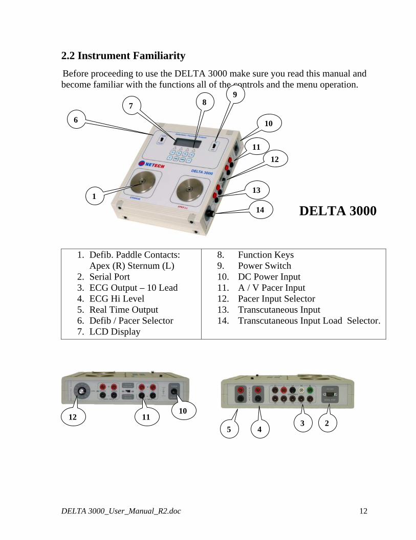
2.2 Instrument Familiarity
Before proceeding to use the DELTA 3000 make sure you read this manual and become familiar with the functions all of the controls and the menu operation.
8
11
14
13
12
10
9
7
6
1
DELTA 3000
1. Defib. Paddle Contacts: Apex (R) Sternum (L) 2. Serial Port 3. ECG Output – 10 Lead 4. ECG Hi Level 5. Real Time Output 6. Defib / Pacer Selector 7. LCD Display
8. Function Keys 9. Power Switch 10. DC Power Input 11. A / V Pacer Input 12. Pacer Input Selector 13. Transcutaneous Input 14. Transcutaneous Input Load Selector.
12 11 10
2 3 45
DELTA 3000_User_Manual_R2.doc 12
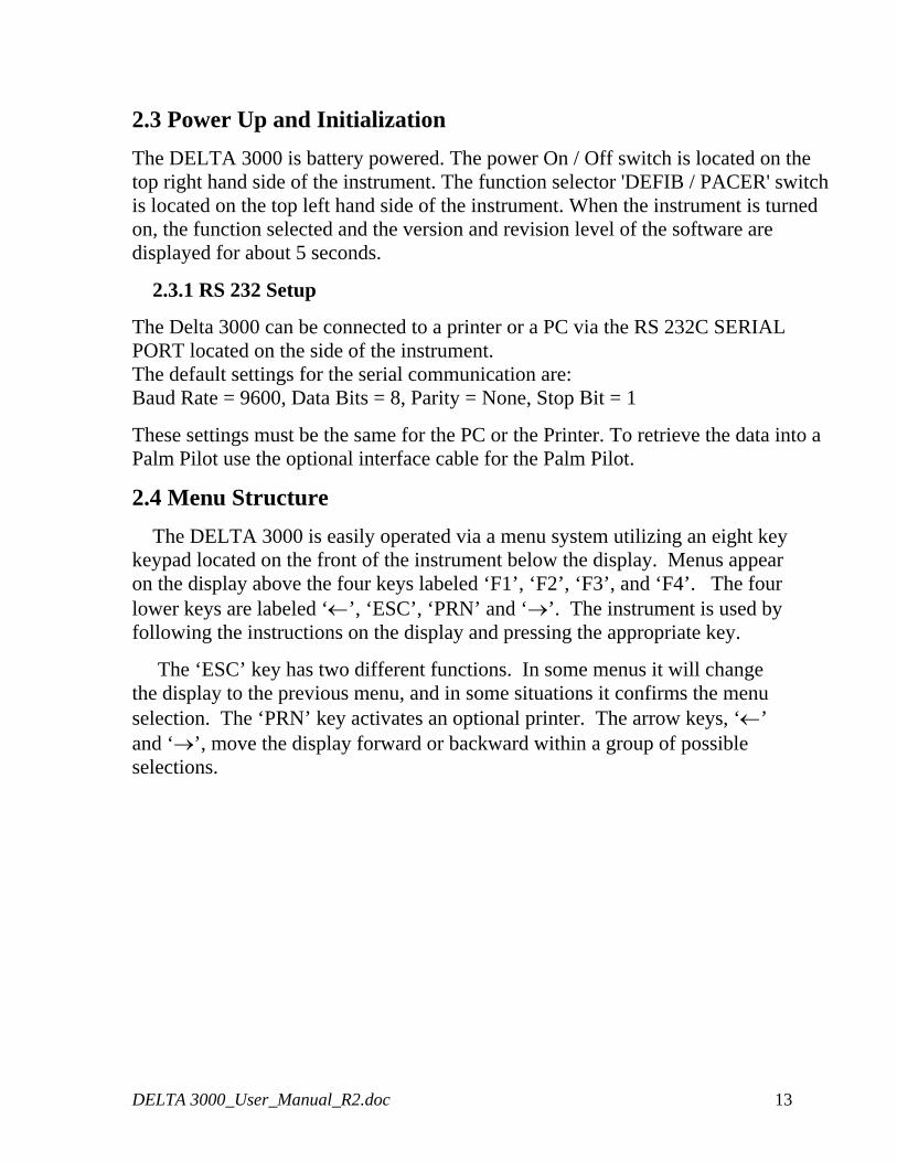
2.3 Power Up and Initialization
The DELTA 3000 is battery powered. The power On / Off switch is located on the top right hand side of the instrument. The function selector 'DEFIB / PACER' switch is located on the top left hand side of the instrument. When the instrument is turned on, the function selected and the version and revision level of the software are displayed for about 5 seconds.
2.3.1 RS 232 Setup
The Delta 3000 can be connected to a printer or a PC via the RS 232C SERIAL PORT located on the side of the instrument. The default settings for the serial communication are: Baud Rate = 9600, Data Bits = 8, Parity = None, Stop Bit = 1
These settings must be the same for the PC or the Printer. To retrieve the data into a Palm Pilot use the optional interface cable for the Palm Pilot.
2.4 Menu Structure
The DELTA 3000 is easily operated via a menu system utilizing an eight key keypad located on the front of the instrument below the display. Menus appear on the display above the four keys labeled ‘F1’, ‘F2’, ‘F3’, and ‘F4’. The four lower keys are labeled ‘←’, ‘ESC’, ‘PRN’ and ‘→’. The instrument is used by following the instructions on the display and pressing the appropriate key.
The ‘ESC’ key has two different functions. In some menus it will change the display to the previous menu, and in some situations it confirms the menu selection. The ‘PRN’ key activates an optional printer. The arrow keys, ‘←’ and ‘→’, move the display forward or backward within a group of possible selections.
DELTA 3000_User_Manual_R2.doc 13
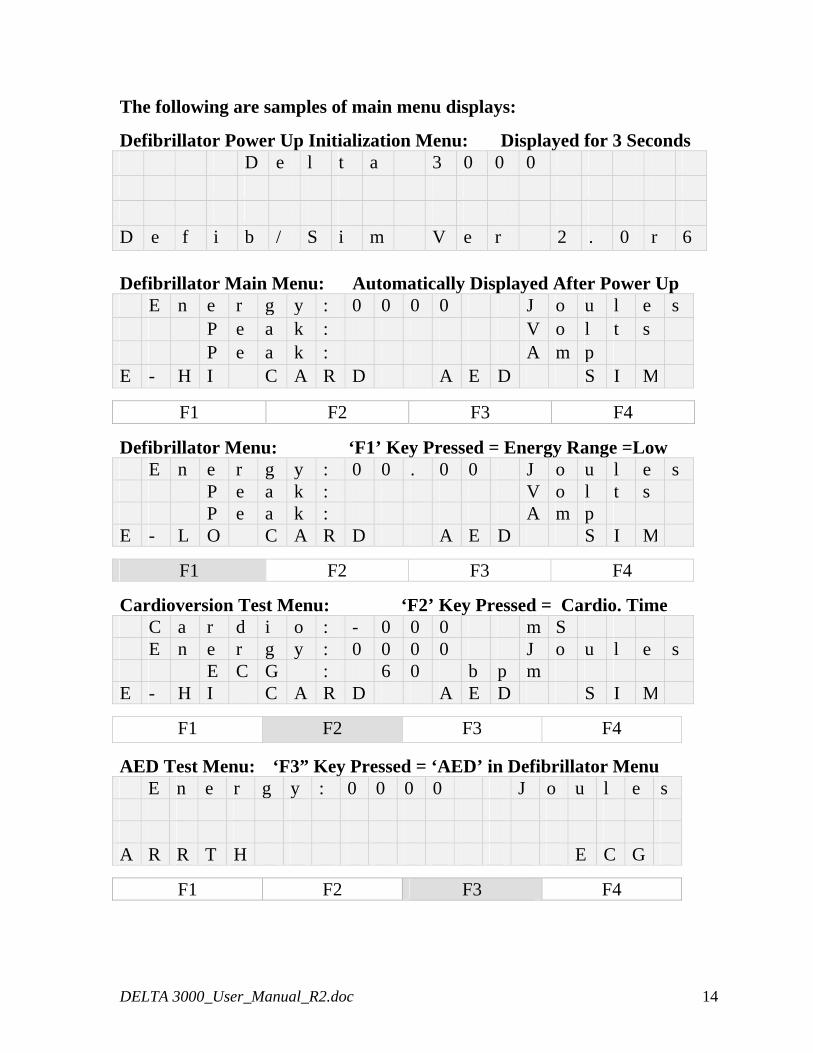
The following are samples of main menu displays:
Defibrillator Power Up Initialization Menu: Displayed for 3 Seconds D e l t a 3 0 0 0 D e f i b / S i m V e r 2 . 0 r 6 Defibrillator Main Menu: Automatically Displayed After Power Up E n e r g y : 0 0 0 0 J o u l e s P e a k : V o l t s P e a k : A m p E - H I C A R D A E D S I M
F1 F2 F3 F4
Defibrillator Menu: ‘F1’ Key Pressed = Energy Range =Low E n e r g y : 0 0 . 0 0 J o u l e s P e a k : V o l t s P e a k : A m p E - L O C A R D A E D S I M
F1 F2 F3 F4
Cardioversion Test Menu: ‘F2’ Key Pressed = Cardio. Time C a r d i o : - 0 0 0 m S E n e r g y : 0 0 0 0 J o u l e s E C G : 6 0 b p m E - H I C A R D A E D S I M
F1 F2 F3 F4
AED Test Menu: ‘F3” Key Pressed = ‘AED’ in Defibrillator Menu E n e r g y : 0 0 0 0 J o u l e s A R R T H E C G
F1 F2 F3 F4
DELTA 3000_User_Manual_R2.doc 14
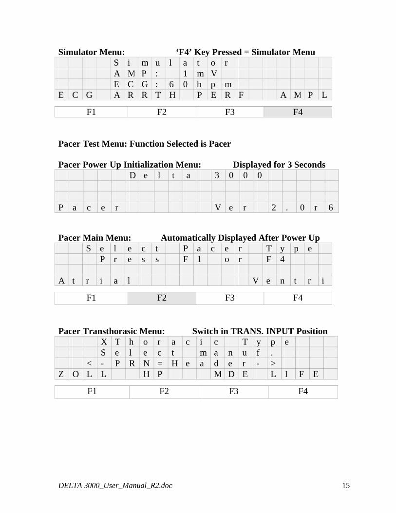
Simulator Menu: ‘F4’ Key Pressed = Simulator Menu S i m u l a t o r A M P : 1 m V E C G : 6 0 b p m E C G A R R T H P E R F A M P L
F1 F2 F3 F4 Pacer Test Menu: Function Selected is Pacer Pacer Power Up Initialization Menu: Displayed for 3 Seconds D e l t a 3 0 0 0 P a c e r V e r 2 . 0 r 6 Pacer Main Menu: Automatically Displayed After Power Up S e l e c t P a c e r T y p e P r e s s F 1 o r F 4 A t r i a l V e n t r i
F1 F2 F3 F4 Pacer Transthorasic Menu: Switch in TRANS. INPUT Position X T h o r a c i c T y p e S e l e c t m a n u f . < - P R N = H e a d e r - > Z O L L H P M D E L I F E
F1 F2 F3 F4
DELTA 3000_User_Manual_R2.doc 15
2.5 Testing A Defibrillator
2.5.1 Energy Measurement
The DELTA 3000 has high and low energy measurement ranges. Up to 1000 joules may be measured in the high range mode and up to 100 joules may be measured in the low range mode.
A. Turn on the defibrillator to be tested and select the energy output following the manufacturer’s instruction manual.
B. Turn the DELTA 3000 on and move the function selector switch to the DEFIB mode. The Defibrillator Main Menu, Figure 1, will be displayed.
C. The DELTA 3000 is in the energy measurement mode and is ready to make an energy measurement.
D. To measure energy in the low range press the F1 key. ‘E-HI’ will change to ‘E-LO’ as in Figure 2.
E. To measure the energy, discharge the defibrillator paddles. F. In the low range, if the discharged energy exceeds 100
joules, the display will flash HIGH.
DELTA 3000_User_Manual_R2.doc 16
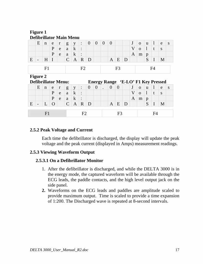
Figure 1 Defibrillator Main Menu E n e r g y : 0 0 0 0 J o u l e s P e a k : V o l t s P e a k : A m p E - H I C A R D A E D S I M
F1 F2 F3 F4
Figure 2 Defibrillator Menu: Energy Range ‘E-LO’ F1 Key Pressed E n e r g y : 0 0 . 0 0 J o u l e s P e a k : V o l t s P e a k : A m p E - L O C A R D A E D S I M
F1 F2 F3 F4 2.5.2 Peak Voltage and Current
Each time the defibrillator is discharged, the display will update the peak voltage and the peak current (displayed in Amps) measurement readings.
2.5.3 Viewing Waveform Output
2.5.3.1 On a Defibrillator Monitor
1. After the defibrillator is discharged, and while the DELTA 3000 is in the energy mode, the captured waveform will be available through the ECG leads, the paddle contacts, and the high level output jack on the side panel.
2. Waveforms on the ECG leads and paddles are amplitude scaled to provide maximum output. Time is scaled to provide a time expansion of 1:200. The Discharged wave is repeated at 8-second intervals.
DELTA 3000_User_Manual_R2.doc 17
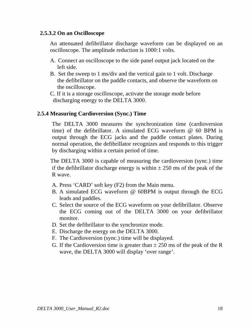
2.5.3.2 On an Oscilloscope
An attenuated defibrillator discharge waveform can be displayed on an oscilloscope. The amplitude reduction is 1000:1 volts.
A. Connect an oscilloscope to the side panel output jack located on the left side. B. Set the sweep to 1 ms/div and the vertical gain to 1 volt. Discharge the defibrillator on the paddle contacts, and observe the waveform on the oscilloscope. C. If it is a storage oscilloscope, activate the storage mode before
discharging energy to the DELTA 3000. 2.5.4 Measuring Cardioversion (Sync.) Time
The DELTA 3000 measures the synchronization time (cardioversion time) of the defibrillator. A simulated ECG waveform @ 60 BPM is output through the ECG jacks and the paddle contact plates. During normal operation, the defibrillator recognizes and responds to this trigger by discharging within a certain period of time.
The DELTA 3000 is capable of measuring the cardioversion (sync.) time if the defibrillator discharge energy is within ± 250 ms of the peak of the R wave.
A. Press ‘CARD’ soft key (F2) from the Main menu. B. A simulated ECG waveform @ 60BPM is output through the ECG
leads and paddles. C. Select the source of the ECG waveform on your defibrillator. Observe
the ECG coming out of the DELTA 3000 on your defibrillator monitor.
D. Set the defibrillator to the synchronize mode. E. Discharge the energy on the DELTA 3000. F. The Cardioversion (sync.) time will be displayed. G. If the Cardioversion time is greater than ± 250 ms of the peak of the R
wave, the DELTA 3000 will display ‘over range’.
DELTA 3000_User_Manual_R2.doc 18
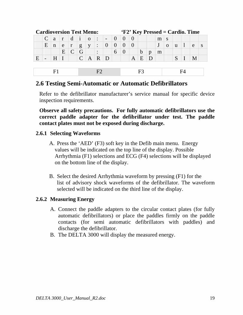
Cardioversion Test Menu: ‘F2’ Key Pressed = Cardio. Time C a r d i o : - 0 0 0 m s E n e r g y : 0 0 0 0 J o u l e s E C G : 6 0 b p m E - H I C A R D A E D S I M
F1 F2 F3 F4
2.6 Testing Semi-Automatic or Automatic Defibrillators
Refer to the defibrillator manufacturer’s service manual for specific device inspection requirements.
Observe all safety precautions. For fully automatic defibrillators use the correct paddle adapter for the defibrillator under test. The paddle contact plates must not be exposed during discharge.
2.6.1 Selecting Waveforms
A. Press the ‘AED’ (F3) soft key in the Defib main menu. Energy values will be indicated on the top line of the display. Possible Arrhythmia (F1) selections and ECG (F4) selections will be displayed on the bottom line of the display.
B. Select the desired Arrhythmia waveform by pressing (F1) for the list of advisory shock waveforms of the defibrillator. The waveform selected will be indicated on the third line of the display.
2.6.2 Measuring Energy
A. Connect the paddle adapters to the circular contact plates (for fully automatic defibrillators) or place the paddles firmly on the paddle contacts (for semi automatic defibrillators with paddles) and discharge the defibrillator.
B. The DELTA 3000 will display the measured energy.
DELTA 3000_User_Manual_R2.doc 19
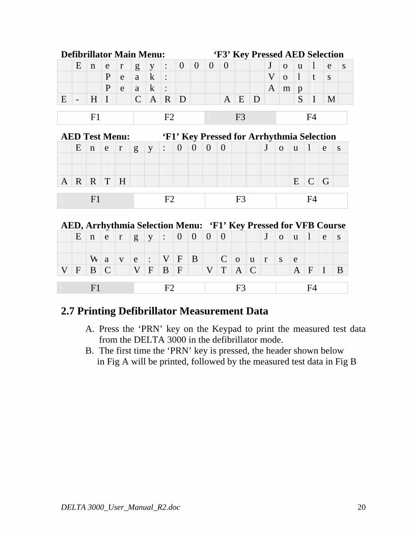
Defibrillator Main Menu: ‘F3’ Key Pressed AED Selection E n e r g y : 0 0 0 0 J o u l e s P e a k : V o l t s P e a k : A m p E - H I C A R D A E D S I M
F1 F2 F3 F4
AED Test Menu: ‘F1’ Key Pressed for Arrhythmia Selection E n e r g y : 0 0 0 0 J o u l e s A R R T H E C G
F1 F2 F3 F4
AED, Arrhythmia Selection Menu: ‘F1’ Key Pressed for VFB Course E n e r g y : 0 0 0 0 J o u l e s W a v e : V F B C o u r s e V F B C V F B F V T A C A F I B
F1 F2 F3 F4 2.7 Printing Defibrillator Measurement Data
A. Press the ‘PRN’ key on the Keypad to print the measured test data from the DELTA 3000 in the defibrillator mode.
B. The first time the ‘PRN’ key is pressed, the header shown below in Fig A will be printed, followed by the measured test data in Fig B
DELTA 3000_User_Manual_R2.doc 20
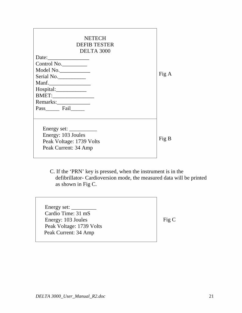
NETECH
DEFIB TESTER DELTA 3000
Date:_______________ Control No._________ Model No.___________ Serial No.__________ Manf._______________ Hospital:___________ BMET:_______________ Remarks:____________ Pass_____ Fail_____
Fig A
Energy set: __________ Energy: 103 Joules Peak Voltage: 1739 Volts Peak Current: 34 Amp
Fig B
C. If the ‘PRN’ key is pressed, when the instrument is in the defibrillator- Cardioversion mode, the measured data will be printed as shown in Fig C.
Energy set: _________ Cardio Time: 31 mS Energy: 103 Joules Peak Voltage: 1739 Volts
Peak Current: 34 Amp
Fig C
DELTA 3000_User_Manual_R2.doc 21
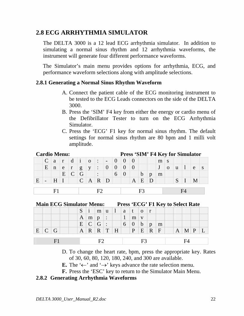
2.8 ECG ARRHYTHMIA SIMULATOR
The DELTA 3000 is a 12 lead ECG arrhythmia simulator. In addition to simulating a normal sinus rhythm and 12 arrhythmia waveforms, the instrument will generate four different performance waveforms.
The Simulator’s main menu provides options for arrhythmia, ECG, and performance waveform selections along with amplitude selections.
2.8.1 Generating a Normal Sinus Rhythm Waveform
A. Connect the patient cable of the ECG monitoring instrument to be tested to the ECG Leads connectors on the side of the DELTA 3000.
B. Press the ‘SIM’ F4 key from either the energy or cardio menu of the Defibrillator Tester to turn on the ECG Arrhythmia Simulator.
C. Press the ‘ECG’ F1 key for normal sinus rhythm. The default settings for normal sinus rhythm are 80 bpm and 1 milli volt amplitude.
Cardio Menu: Press ‘SIM’ F4 Key for Simulator C a r d i o : - 0 0 0 m s E n e r g y : 0 0 0 0 J o u l e s E C G : 6 0 b p m E - H I C A R D A E D S I M
F1 F2 F3 F4 Main ECG Simulator Menu: Press ‘ECG’ F1 Key to Select Rate S i m u l a t o r A m p : 1 m v E C G : 6 0 b p m E C G A R R T H P E R F A M P L
F1 F2 F3 F4
D. To change the heart rate, bpm, press the appropriate key. Rates of 30, 60, 80, 120, 180, 240, and 300 are available.
E. The ‘←’ and ‘→’ keys advance the rate selection menu. F. Press the ‘ESC’ key to return to the Simulator Main Menu.
2.8.2 Generating Arrhythmia Waveforms
DELTA 3000_User_Manual_R2.doc 22
A. Press the ‘ARRTH’ F2 key to view the available arrhythmias. The default arrhythmia is VFB course and the amplitude is set at 1 millivolt.
B. The ‘←’ and ‘→’ keys to advance through the arrhythmia selection menu.
C. Press the appropriate key to select an arrhythmia waveform. D. The selected arrhythmia will be displayed on the third line of
the simulator menu display.
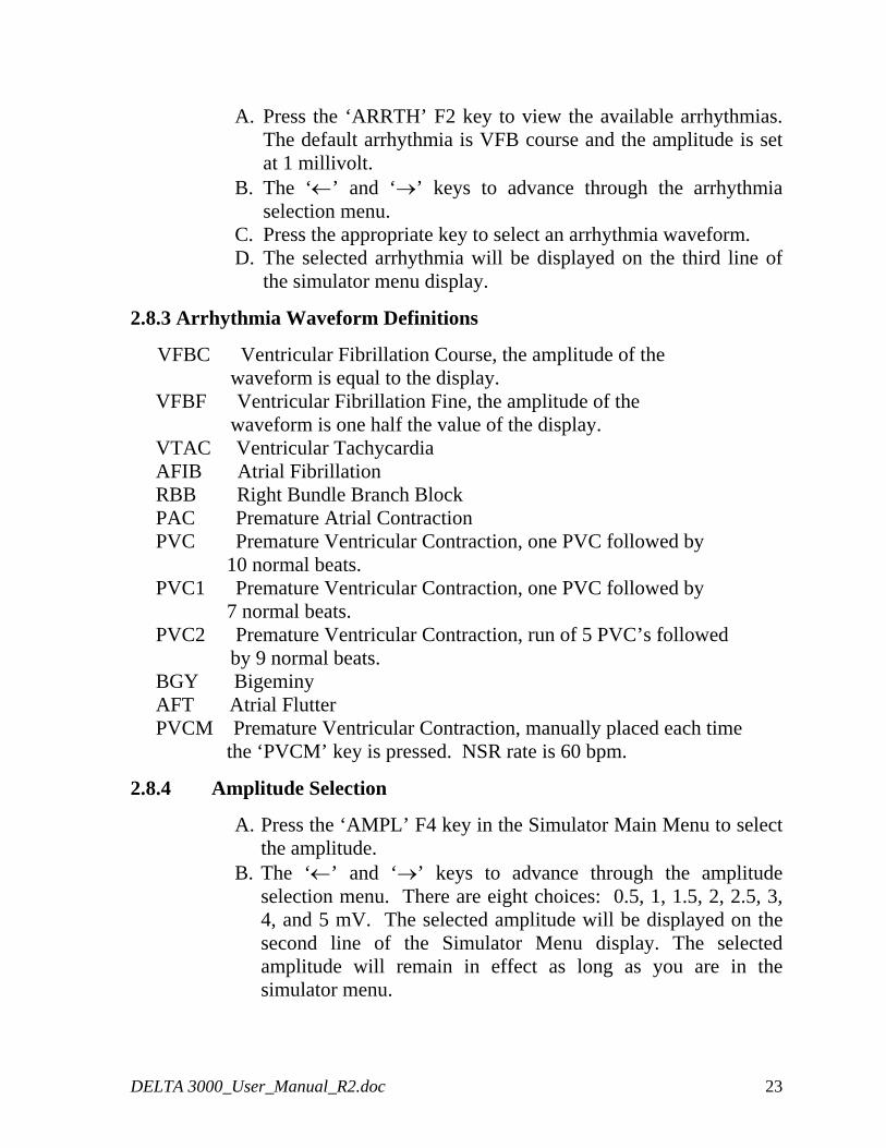
2.8.3 Arrhythmia Waveform Definitions
VFBC Ventricular Fibrillation Course, the amplitude of the waveform is equal to the display. VFBF Ventricular Fibrillation Fine, the amplitude of the waveform is one half the value of the display. VTAC Ventricular Tachycardia AFIB Atrial Fibrillation RBB Right Bundle Branch Block PAC Premature Atrial Contraction PVC Premature Ventricular Contraction, one PVC followed by 10 normal beats. PVC1 Premature Ventricular Contraction, one PVC followed by 7 normal beats. PVC2 Premature Ventricular Contraction, run of 5 PVC’s followed by 9 normal beats. BGY Bigeminy AFT Atrial Flutter PVCM Premature Ventricular Contraction, manually placed each time the ‘PVCM’ key is pressed. NSR rate is 60 bpm.
2.8.4 Amplitude Selection
A. Press the ‘AMPL’ F4 key in the Simulator Main Menu to select the amplitude.
B. The ‘←’ and ‘→’ keys to advance through the amplitude selection menu. There are eight choices: 0.5, 1, 1.5, 2, 2.5, 3, 4, and 5 mV. The selected amplitude will be displayed on the second line of the Simulator Menu display. The selected amplitude will remain in effect as long as you are in the simulator menu.
DELTA 3000_User_Manual_R2.doc 23
Note: When the DELTA 3000 is switched to the energy mode from the simulator menu, the waveform amplitude will return to the default value of 1 mV.
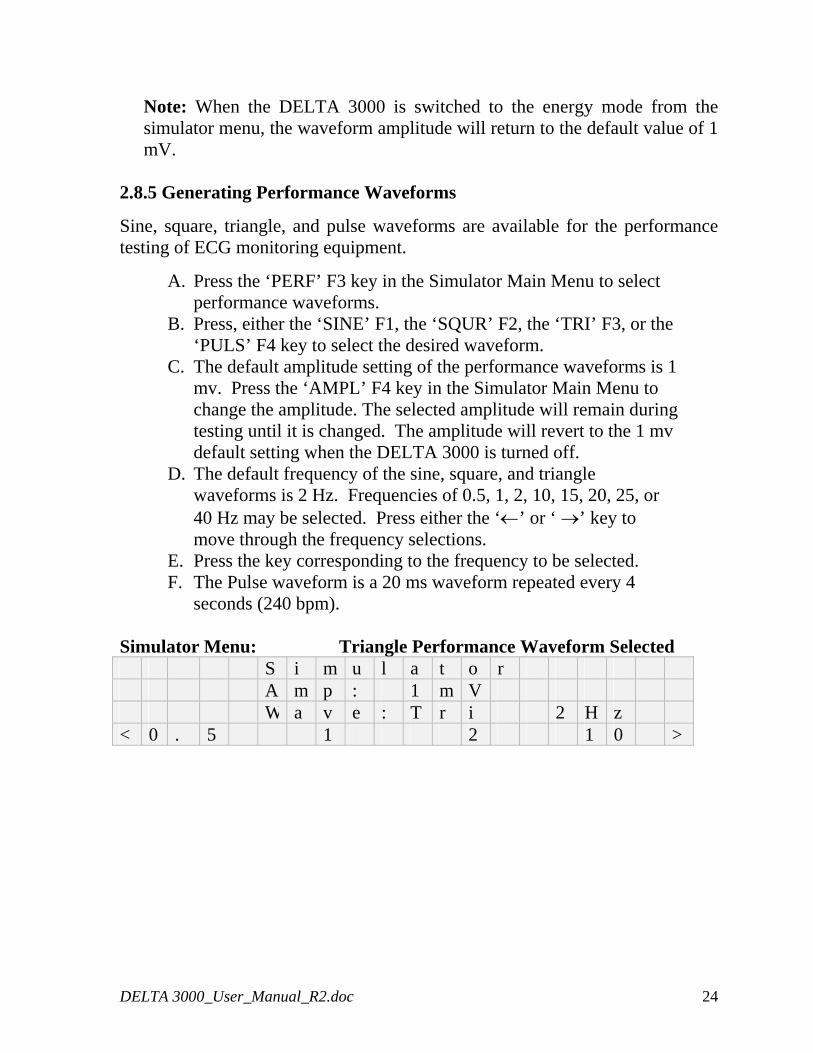
2.8.5 Generating Performance Waveforms
Sine, square, triangle, and pulse waveforms are available for the performance testing of ECG monitoring equipment.
A. Press the ‘PERF’ F3 key in the Simulator Main Menu to select performance waveforms.
B. Press, either the ‘SINE’ F1, the ‘SQUR’ F2, the ‘TRI’ F3, or the ‘PULS’ F4 key to select the desired waveform.
C. The default amplitude setting of the performance waveforms is 1 mv. Press the ‘AMPL’ F4 key in the Simulator Main Menu to change the amplitude. The selected amplitude will remain during testing until it is changed. The amplitude will revert to the 1 mv default setting when the DELTA 3000 is turned off.
D. The default frequency of the sine, square, and triangle waveforms is 2 Hz. Frequencies of 0.5, 1, 2, 10, 15, 20, 25, or 40 Hz may be selected. Press either the ‘←’ or ‘ →’ key to move through the frequency selections.
E. Press the key corresponding to the frequency to be selected. F. The Pulse waveform is a 20 ms waveform repeated every 4
seconds (240 bpm).
Simulator Menu: Triangle Performance Waveform Selected S i m u l a t o r A m p : 1 m V W a v e : T r i 2 H z < 0 . 5 1 2 1 0 >
DELTA 3000_User_Manual_R2.doc 24
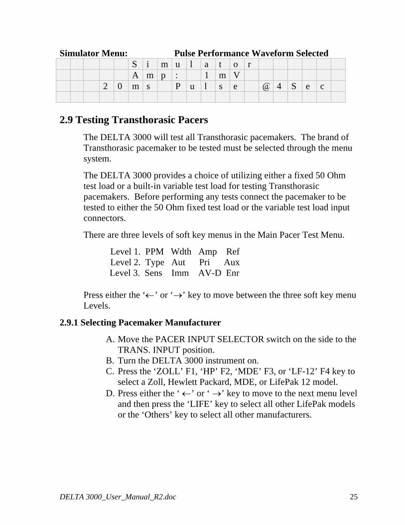
Simulator Menu: Pulse Performance Waveform Selected S i m u l a t o r A m p : 1 m V 2 0 m s P u l s e @ 4 S e c
2.9 Testing Transthorasic Pacers
The DELTA 3000 will test all Transthorasic pacemakers. The brand of Transthorasic pacemaker to be tested must be selected through the menu system.
The DELTA 3000 provides a choice of utilizing either a fixed 50 Ohm test load or a built-in variable test load for testing Transthorasic pacemakers. Before performing any tests connect the pacemaker to be tested to either the 50 Ohm fixed test load or the variable test load input connectors.
There are three levels of soft key menus in the Main Pacer Test Menu.
Level 1. PPM Wdth Amp Ref Level 2. Type Aut Pri Aux
Level 3. Sens Imm AV-D Enr
Press either the ‘←’ or ‘→’ key to move between the three soft key menu Levels.
2.9.1 Selecting Pacemaker Manufacturer
A. Move the PACER INPUT SELECTOR switch on the side to the TRANS. INPUT position.
B. Turn the DELTA 3000 instrument on. C. Press the ‘ZOLL’ F1, ‘HP’ F2, ‘MDE’ F3, or ‘LF-12’ F4 key to
select a Zoll, Hewlett Packard, MDE, or LifePak 12 model.
D. Press either the ‘ ←’ or ‘ →’ key to move to the next menu level and then press the ‘LIFE’ key to select all other LifePak models or the ‘Others’ key to select all other manufacturers.
DELTA 3000_User_Manual_R2.doc 25
2.9.2 Selecting 50 Ohm Fixed Test Load
A. Move the Mode switch on the DELTA 3000 to PACER. B. Move the pacer input selector switch on the side panel to the
TRANS. INPUT position. C. Connect the transcutaneous pacer to the TRANS INPUT fixed
50 OHMS input connectors (see the next section for variable loads).
D. Turn the DELTA 3000 on. E. Turn the pacer on. F. Select the desired pacer manufacturer and perform the tests.
2.9.3 Selecting Variable Test Loads
A. Move the Mode switch on the DELTA 3000 to PACER. B. Move the pacer input selector switch on the side panel to the
TRANS. INPUT position. C. Connect the transcutaneous pacer to the VAR. LOAD input
connectors. D. Rotate the LOAD SELECTOR switch to the desired test load
for the measurement. E. Turn the DELTA 3000 on. F. Turn the pacer on. G. Select the desired pacer manufacturer and perform the tests.
Note: Turn the pacemaker off before selecting another test load.
2.9.4 Measuring Pulse Parameters: Rate, Width, and Amplitude
A. Press ‘PPM’ Key F1 to measure the Rate.
B. Press ‘Wdth’ Key F2 to measure the Width.
C. Press ‘Amp’ Key F3 to measure the Amplitude.
Note: The DELTA 3000 pacer will continuously measure the parameters and update the display with the new values. Pressing F1, F2, or F3 will select the measurement priority. The parameter selected will be updated first followed by the others.
DELTA 3000_User_Manual_R2.doc 26
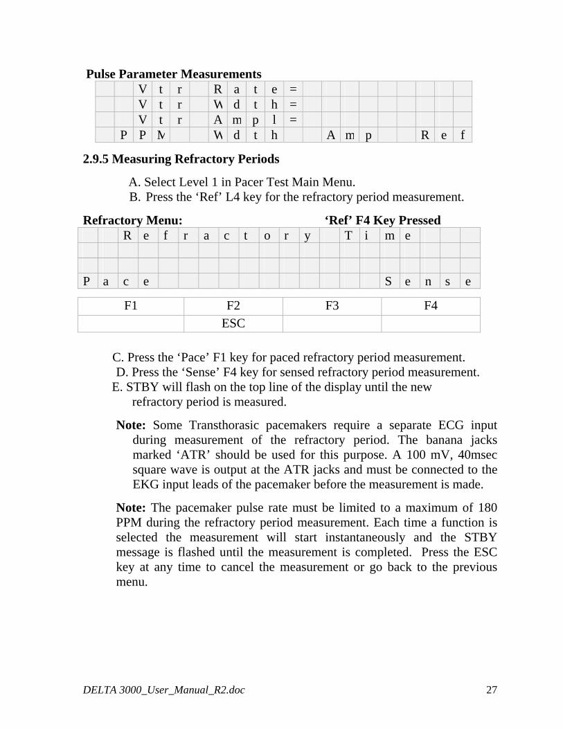
Pulse Parameter Measurements V t r R a t e = V t r W d t h = V t r A m p l = P P M W d t h A m p R e f
2.9.5 Measuring Refractory Periods
A. Select Level 1 in Pacer Test Main Menu. B. Press the ‘Ref’ L4 key for the refractory period measurement.
Refractory Menu: ‘Ref’ F4 Key Pressed R e f r a c t o r y T i m e P a c e S e n s e
F1 F2 F3 F4 ESC
C. Press the ‘Pace’ F1 key for paced refractory period measurement. D. Press the ‘Sense’ F4 key for sensed refractory period measurement.
E. STBY will flash on the top line of the display until the new refractory period is measured.
Note: Some Transthorasic pacemakers require a separate ECG input during measurement of the refractory period. The banana jacks marked ‘ATR’ should be used for this purpose. A 100 mV, 40msec square wave is output at the ATR jacks and must be connected to the EKG input leads of the pacemaker before the measurement is made.
Note: The pacemaker pulse rate must be limited to a maximum of 180 PPM during the refractory period measurement. Each time a function is selected the measurement will start instantaneously and the STBY message is flashed until the measurement is completed. Press the ESC key at any time to cancel the measurement or go back to the previous menu.
DELTA 3000_User_Manual_R2.doc 27
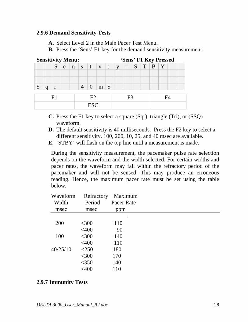
2.9.6 Demand Sensitivity Tests
A. Select Level 2 in the Main Pacer Test Menu. B. Press the ‘Sens’ F1 key for the demand sensitivity measurement.
Sensitivity Menu: ‘Sens’ F1 Key Pressed S e n s t v t y = S T B Y S q r 4 0 m S
F1 F2 F3 F4 ESC
C. Press the F1 key to select a square (Sqr), triangle (Tri), or (SSQ) waveform.
D. The default sensitivity is 40 milliseconds. Press the F2 key to select a different sensitivity. 100, 200, 10, 25, and 40 msec are available.
E. ‘STBY’ will flash on the top line until a measurement is made.
During the sensitivity measurement, the pacemaker pulse rate selection depends on the waveform and the width selected. For certain widths and pacer rates, the waveform may fall within the refractory period of the pacemaker and will not be sensed. This may produce an erroneous reading. Hence, the maximum pacer rate must be set using the table below.
Waveform Refractory Maximum Width Period Pacer Rate msec msec ppm 200 <300 110 <400 90 100 <300 140 <400 110 40/25/10 <250 180 <300 170 <350 140 <400 110
2.9.7 Immunity Tests
DELTA 3000_User_Manual_R2.doc 28
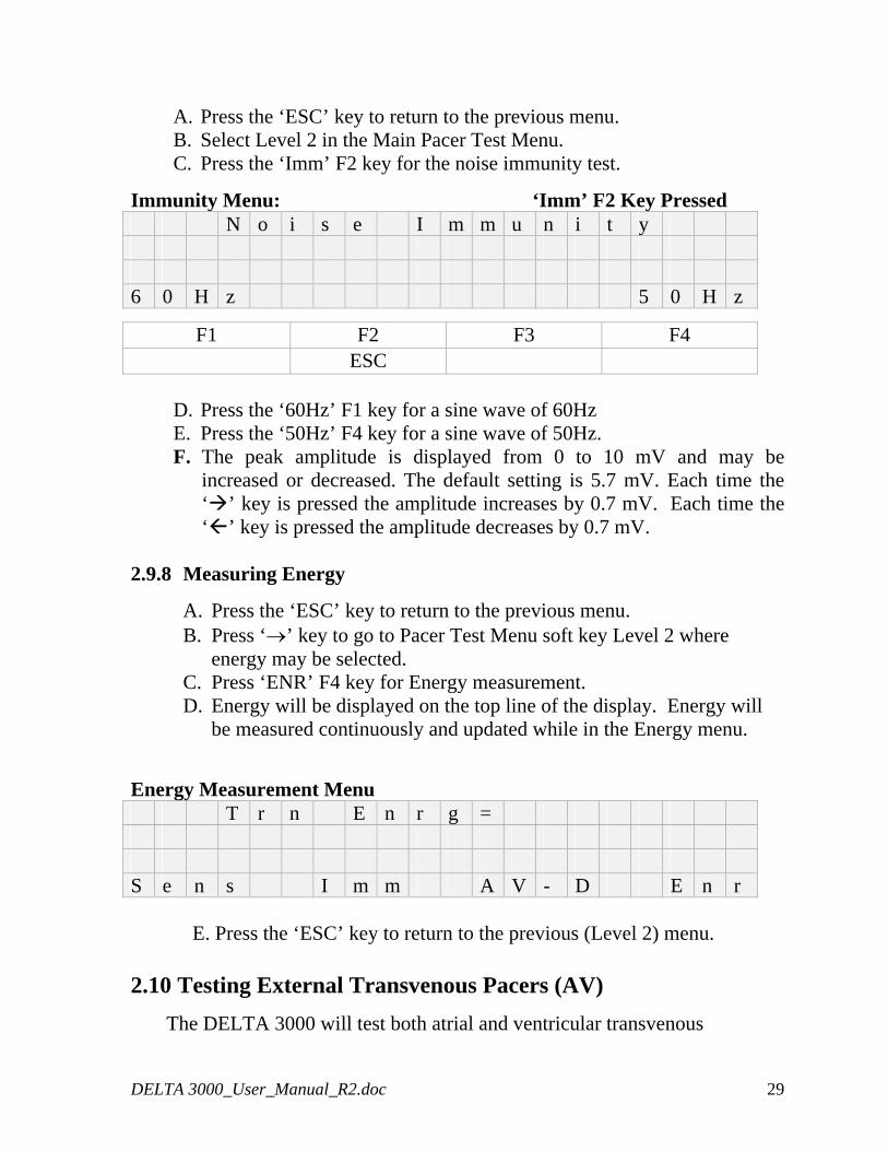
A. Press the ‘ESC’ key to return to the previous menu. B. Select Level 2 in the Main Pacer Test Menu. C. Press the ‘Imm’ F2 key for the noise immunity test.
Immunity Menu: ‘Imm’ F2 Key Pressed N o i s e I m m u n i t y 6 0 H z 5 0 H z
F1 F2 F3 F4 ESC
D. Press the ‘60Hz’ F1 key for a sine wave of 60Hz E. Press the ‘50Hz’ F4 key for a sine wave of 50Hz. F. The peak amplitude is displayed from 0 to 10 mV and may be
increased or decreased. The default setting is 5.7 mV. Each time the ‘ ’ key is pressed the amplitude increases by 0.7 mV. Each time the ‘ ’ key is pressed the amplitude decreases by 0.7 mV.
2.9.8 Measuring Energy
A. Press the ‘ESC’ key to return to the previous menu. B. Press ‘→’ key to go to Pacer Test Menu soft key Level 2 where
energy may be selected. C. Press ‘ENR’ F4 key for Energy measurement. D. Energy will be displayed on the top line of the display. Energy will
be measured continuously and updated while in the Energy menu.
Energy Measurement Menu T r n E n r g = S e n s I m m A V - D E n r
E. Press the ‘ESC’ key to return to the previous (Level 2) menu. 2.10 Testing External Transvenous Pacers (AV)
The DELTA 3000 will test both atrial and ventricular transvenous
DELTA 3000_User_Manual_R2.doc 29
pacemakers. Before performing any tests connect the pacemaker to be tested to either the ATR (Atrial) or VENT ( Ventricular) A-V INPUT connectors on the side panel.
A. Move the Pacer Input Selector switch to the A.V. INPUT position. B. Turn the DELTA 3000 on. C. Press F1 ‘Atrial’ or F4 ‘Ventri’ to select pacer type. D. Perform the measurements in section 2.10.1
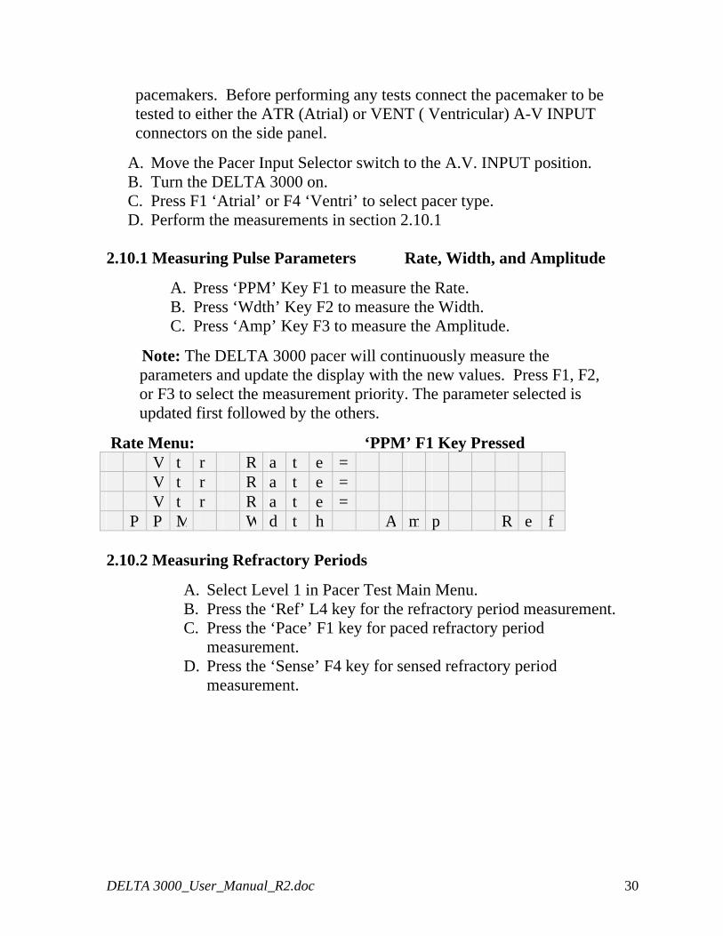
2.10.1 Measuring Pulse Parameters Rate, Width, and Amplitude
A. Press ‘PPM’ Key F1 to measure the Rate. B. Press ‘Wdth’ Key F2 to measure the Width. C. Press ‘Amp’ Key F3 to measure the Amplitude.
Note: The DELTA 3000 pacer will continuously measure the parameters and update the display with the new values. Press F1, F2, or F3 to select the measurement priority. The parameter selected is updated first followed by the others.
Rate Menu: ‘PPM’ F1 Key Pressed V t r R a t e = V t r R a t e = V t r R a t e = P P M W d t h A m p R e f 2.10.2 Measuring Refractory Periods
A. Select Level 1 in Pacer Test Main Menu. B. Press the ‘Ref’ L4 key for the refractory period measurement. C. Press the ‘Pace’ F1 key for paced refractory period
measurement. D. Press the ‘Sense’ F4 key for sensed refractory period
measurement.
DELTA 3000_User_Manual_R2.doc 30
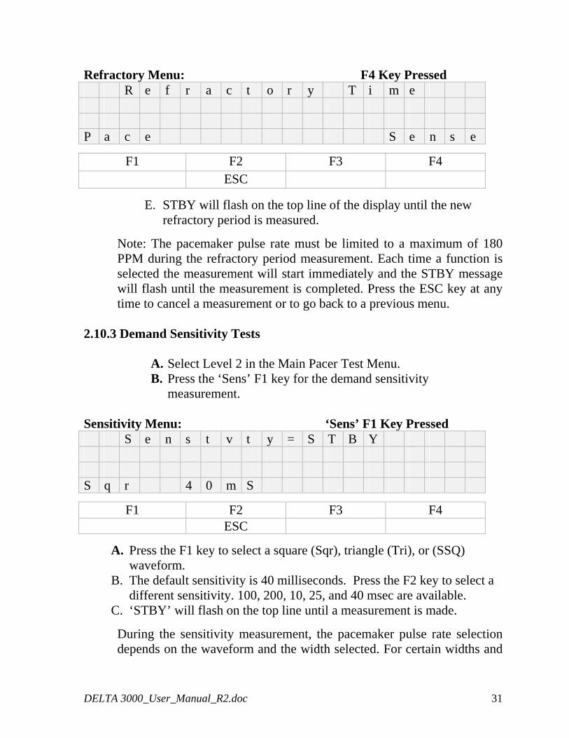
Refractory Menu: F4 Key Pressed R e f r a c t o r y T i m e P a c e S e n s e
F1 F2 F3 F4 ESC
E. STBY will flash on the top line of the display until the new refractory period is measured.
Note: The pacemaker pulse rate must be limited to a maximum of 180 PPM during the refractory period measurement. Each time a function is selected the measurement will start immediately and the STBY message will flash until the measurement is completed. Press the ESC key at any time to cancel a measurement or to go back to a previous menu.
2.10.3 Demand Sensitivity Tests
A. Select Level 2 in the Main Pacer Test Menu.
B. Press the ‘Sens’ F1 key for the demand sensitivity measurement.
Sensitivity Menu: ‘Sens’ F1 Key Pressed S e n s t v t y = S T B Y S q r 4 0 m S
F1 F2 F3 F4 ESC
A. Press the F1 key to select a square (Sqr), triangle (Tri), or (SSQ) waveform.
B. The default sensitivity is 40 milliseconds. Press the F2 key to select a different sensitivity. 100, 200, 10, 25, and 40 msec are available.
C. ‘STBY’ will flash on the top line until a measurement is made.
During the sensitivity measurement, the pacemaker pulse rate selection depends on the waveform and the width selected. For certain widths and
DELTA 3000_User_Manual_R2.doc 31
pacer rates, the waveform may fall within the refractory period of the pacemaker and will not be sensed. This may produce an erroneous reading. Hence, the maximum pacer rate must be set using the table below.
Waveform Refractory Maximum Width Period Pacer Rate msec msec ppm 200 <300 110 <400 90 100 <300 140 <400 110 40/25/10 <250 180 <300 170 <350 140 <400 110
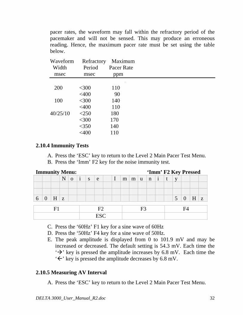
2.10.4 Immunity Tests
A. Press the ‘ESC’ key to return to the Level 2 Main Pacer Test Menu. B. Press the ‘Imm’ F2 key for the noise immunity test.
Immunity Menu: ‘Imm’ F2 Key Pressed N o i s e I m m u n i t y 6 0 H z 5 0 H z
F1 F2 F3 F4 ESC
C. Press the ‘60Hz’ F1 key for a sine wave of 60Hz D. Press the ‘50Hz’ F4 key for a sine wave of 50Hz. E. The peak amplitude is displayed from 0 to 101.9 mV and may be
increased or decreased. The default setting is 54.3 mV. Each time the ‘ ’ key is pressed the amplitude increases by 6.8 mV. Each time the ‘ ’ key is pressed the amplitude decreases by 6.8 mV.
2.10.5 Measuring AV Interval
A. Press the ‘ESC’ key to return to the Level 2 Main Pacer Test Menu.
DELTA 3000_User_Manual_R2.doc 32
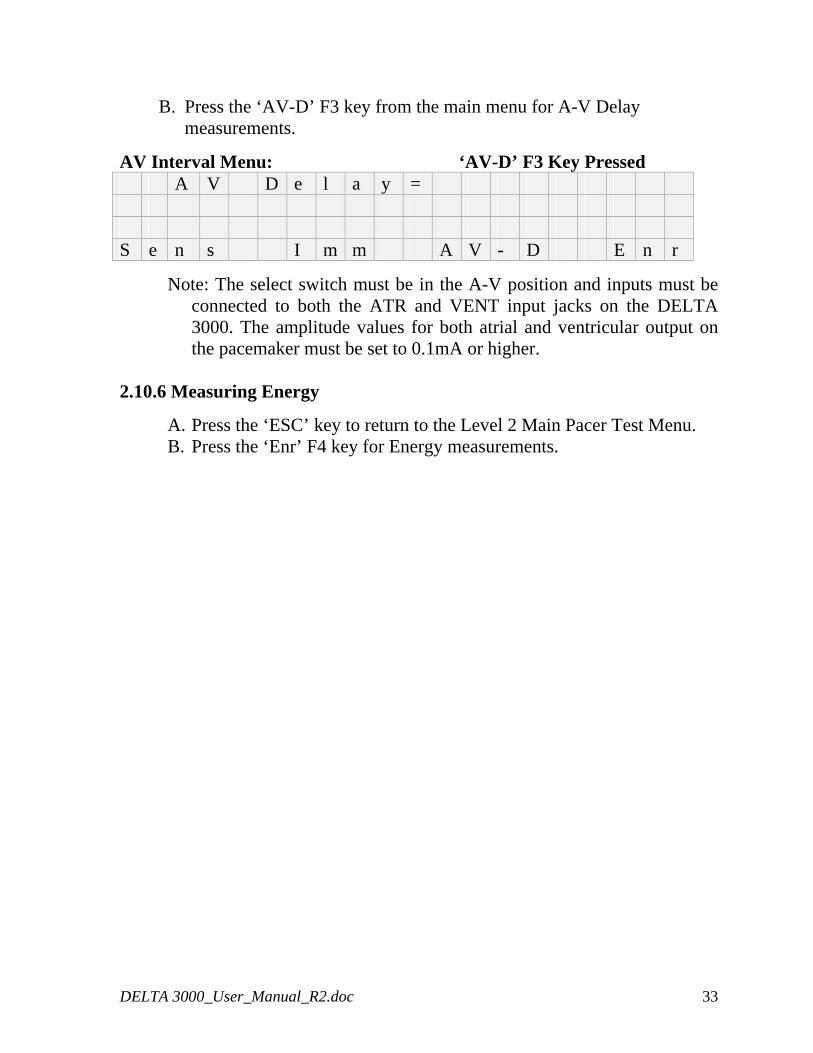
B. Press the ‘AV-D’ F3 key from the main menu for A-V Delay measurements.
AV Interval Menu: ‘AV-D’ F3 Key Pressed A V D e l a y = S e n s I m m A V - D E n r
Note: The select switch must be in the A-V position and inputs must be connected to both the ATR and VENT input jacks on the DELTA 3000. The amplitude values for both atrial and ventricular output on the pacemaker must be set to 0.1mA or higher.
2.10.6 Measuring Energy
A. Press the ‘ESC’ key to return to the Level 2 Main Pacer Test Menu. B. Press the ‘Enr’ F4 key for Energy measurements.
DELTA 3000_User_Manual_R2.doc 33
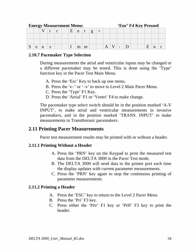
Energy Measurement Menu: ‘Enr’ F4 Key Pressed V t r E n r g = S e n s I m m A V - D E n r
2.10.7 Pacemaker Type Selection
During measurements the atrial and ventricular inputs may be changed or a different pacemaker may be tested. This is done using the ‘Type’ function key in the Pacer Test Main Menu.
A. Press the ‘Esc’ Key to back up one menu. B. Press the ‘←’ or ‘→’ to move to Level 2 Main Pacer Menu. C. Press the ‘Type’ F1 Key. D. Press the ‘Atrial’ F1 or ‘Ventri’ F4 to make change.
The pacemaker type select switch should be in the position marked ‘A-V INPUT’, to make atrial and ventricular measurements in invasive pacemakers, and in the position marked ‘TRANS. INPUT’ to make measurements in Transthorasic pacemakers.
2.11 Printing Pacer Measurements
Pacer test measurement results may be printed with or without a header.
2.11.1 Printing Without a Header
A. Press the ‘PRN’ key on the Keypad to print the measured test data from the DELTA 3000 in the Pacer Test mode.
B. The DELTA 3000 will send data to the printer port each time the display updates with current parameter measurements.
C. Press the ‘PRN’ key again to stop the continuous printing of parameter measurements.
2.11.2 Printing a Header
A. Press the ‘ESC’ key to return to the Level 2 Pacer Menu B. Press the ‘Pri’ F3 key. C. Press either the ‘Prtr’ F1 key or ‘PrH’ F3 key to print the
header.
DELTA 3000_User_Manual_R2.doc 34
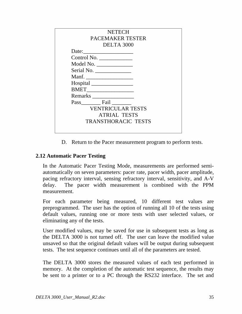
NETECH PACEMAKER TESTER
DELTA 3000 Date:__________________ Control No. ____________ Model No. _____________ Serial No. _____________ Manf. _________________ Hospital _______________ BMET_________________ Remarks _______________ Pass_______ Fail _______
VENTRICULAR TESTS ATRIAL TESTS
TRANSTHORACIC TESTS
D. Return to the Pacer measurement program to perform tests.
2.12 Automatic Pacer Testing
In the Automatic Pacer Testing Mode, measurements are performed semi-automatically on seven parameters: pacer rate, pacer width, pacer amplitude, pacing refractory interval, sensing refractory interval, sensitivity, and A-V delay. The pacer width measurement is combined with the PPM measurement.
For each parameter being measured, 10 different test values are preprogrammed. The user has the option of running all 10 of the tests using default values, running one or more tests with user selected values, or eliminating any of the tests.
User modified values, may be saved for use in subsequent tests as long as the DELTA 3000 is not turned off. The user can leave the modified value unsaved so that the original default values will be output during subsequent tests. The test sequence continues until all of the parameters are tested.
The DELTA 3000 stores the measured values of each test performed in memory. At the completion of the automatic test sequence, the results may be sent to a printer or to a PC through the RS232 interface. The set and
DELTA 3000_User_Manual_R2.doc 35
measured values are compared. If there is a deviation of more than 10%, a comment to that effect is printed.
Note: Test results are saved in the memory during an auto test sequence until the instrument is switched off. This permits multiple copies of the results to be made on the printers and /or PC.
Note: Comprehensive Automatic Pacer Test instructions are being revised and will be supplied later.
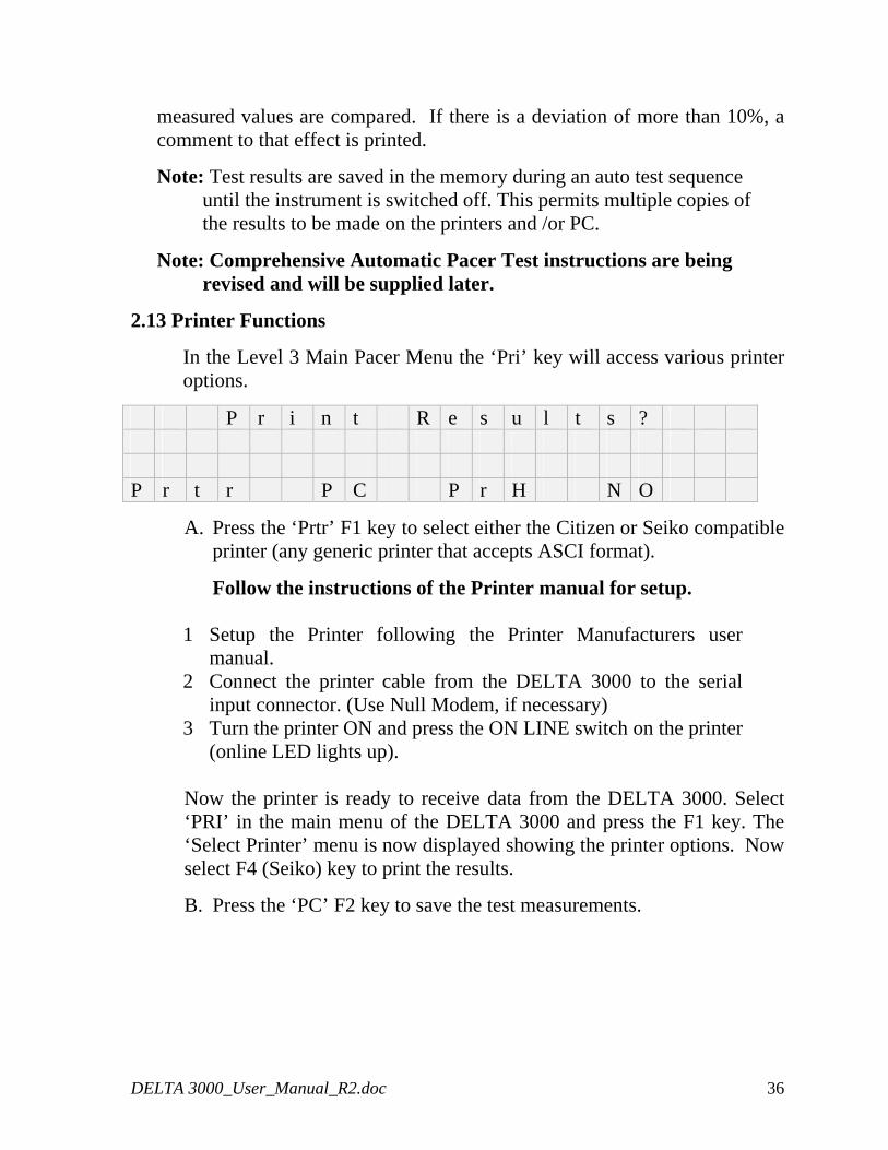
2.13 Printer Functions
In the Level 3 Main Pacer Menu the ‘Pri’ key will access various printer options.
P r i n t R e s u l t s ? P r t r P C P r H N O
A. Press the ‘Prtr’ F1 key to select either the Citizen or Seiko compatible printer (any generic printer that accepts ASCI format).
Follow the instructions of the Printer manual for setup.
1 Setup the Printer following the Printer Manufacturers user manual.
2 Connect the printer cable from the DELTA 3000 to the serial input connector. (Use Null Modem, if necessary)
3 Turn the printer ON and press the ON LINE switch on the printer (online LED lights up).
Now the printer is ready to receive data from the DELTA 3000. Select ‘PRI’ in the main menu of the DELTA 3000 and press the F1 key. The ‘Select Printer’ menu is now displayed showing the printer options. Now select F4 (Seiko) key to print the results.
B. Press the ‘PC’ F2 key to save the test measurements.
DELTA 3000_User_Manual_R2.doc 36
PC Quick Link Software
To store the results in a PC using Quick Link or PC wedge or other Communications software follow these steps:
1 Using the line setting option select: Baud Rate=9600, Data Bits=8, Parity=None, Stop Bits=1.
2 Connect the RS232 cable from the DELTA 3000 to the serial port of the PC (DB-9 connector) and in the Modem setup option of Quick Link select the COM port.
3 Select the file option to Receive File. 4 ”ASCII” and enter a file name to which the DELTA 3000
results are to be stored. 5 Once the above selections have been made press ‘PRI’ in the
main menu of the DELTA 3000 and press the ‘PC’ F2 key for the results to be stored in the given file name.
6 The file can be printed out or edited using any text editor.
C. Press the ‘PrH’ F3 key to print a header.
D. Press the ‘NO’ F4 key to return to the Level 3 Menu.
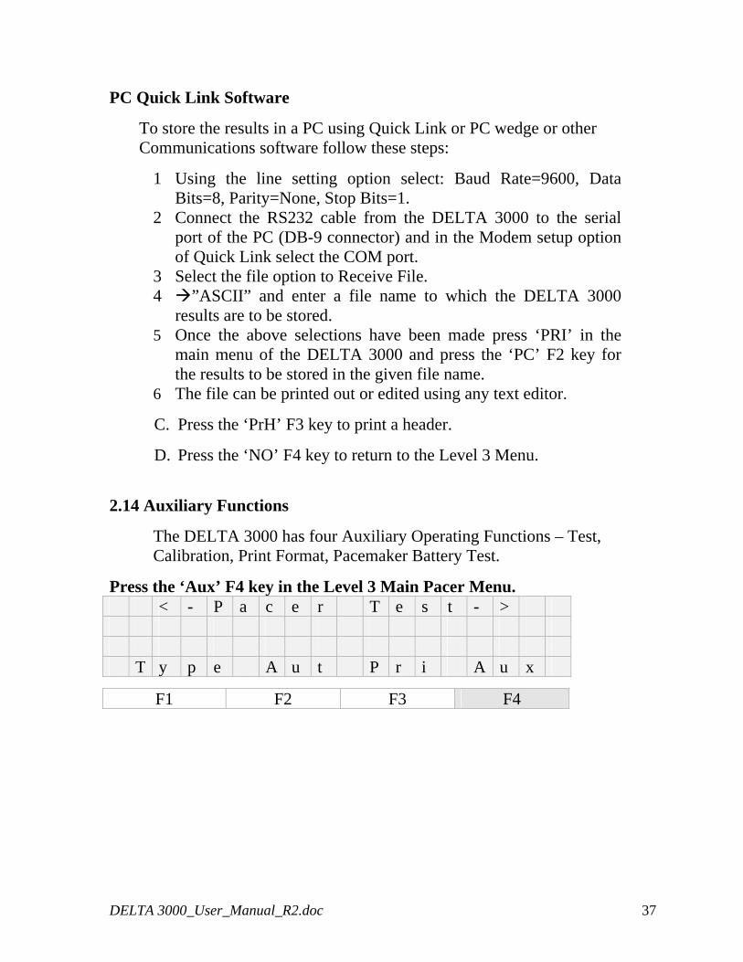
2.14 Auxiliary Functions
The DELTA 3000 has four Auxiliary Operating Functions – Test, Calibration, Print Format, Pacemaker Battery Test.
Press the ‘Aux’ F4 key in the Level 3 Main Pacer Menu. < - P a c e r T e s t - > T y p e A u t P r i A u x
F1 F2 F3 F4
DELTA 3000_User_Manual_R2.doc 37
Auxiliary Functions A u x F u n c t i o n s T s t C a l P r F S B a t T 2.14.1 AV Pacer Test Function
In the AV Pacer Test Mode, the DELTA 3000 inputs a DC output voltage of 100 mill volts ± 5 and displays both the input and the measured values.
A. Select the AV Pacer Mode. B. Press the ‘Tst’ F1 key. C. Place the Pacer Select Switch in the AV Input position. D. Disconnect the input to the DELTA 3000. E. Press the ‘ESC’ key.
AV Pacer Test S e l e c t e d 9 9 . 8 m v M e a s u r e d 1 0 0 . 1 m v
Note: If the measured reading is not within ± 5 % of the selected reading the DELTA 3000 should be recalibrated.
2.14.2 Transcutaneous Pacer Test Function
In the Transcutaneous Pacer Test Mode, the DELTA 3000 outputs a voltage of 10 millivolts ± 0.5. This voltage may be checked with a Voltmeter connected to the Vent jacks of the A-V Input connectors.
A. Select the Transcutaneous Pacer Mode. F. Press the ‘Tst’ F1 key. G. Place the Pacer Select Switch in the TRANS Input
position. H. Disconnect the input to the DELTA 3000. I. Connect the voltmeter to the Vent jacks of the A-V Intput
connectors. J. Press the ‘ESC’ key.
DELTA 3000_User_Manual_R2.doc 38
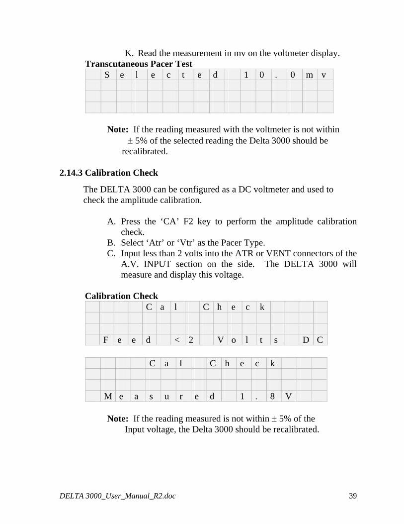
K. Read the measurement in mv on the voltmeter display. Transcutaneous Pacer Test
S e l e c t e d 1 0 . 0 m v
Note: If the reading measured with the voltmeter is not within ± 5% of the selected reading the Delta 3000 should be
recalibrated. 2.14.3 Calibration Check
The DELTA 3000 can be configured as a DC voltmeter and used to check the amplitude calibration.
A. Press the ‘CA’ F2 key to perform the amplitude calibration check.
B. Select ‘Atr’ or ‘Vtr’ as the Pacer Type. C. Input less than 2 volts into the ATR or VENT connectors of the
A.V. INPUT section on the side. The DELTA 3000 will measure and display this voltage.
Calibration Check
C a l C h e c k F e e d < 2 V o l t s D C
C a l C h e c k M e a s u r e d 1 . 8 V
Note: If the reading measured is not within ± 5% of the
Input voltage, the Delta 3000 should be recalibrated.
DELTA 3000_User_Manual_R2.doc 39
2.14.4 Printer Format Selection
Different print formats may be selected. Press the ‘PrFS’ F3 key from the Auxilary Menu, to select a different format. Press the ‘←’ and ‘→’ keys to move through the selections. The selections are listed :
TAB Fix horizontal space LF Line feed FF Form feed CR Carriage return DW Double width print DCLR Reset double width print HW Condensed print HCLR Reset condensed print EMP Emphasize print ECLR Reset emphasize print
DST Double strike CLR Reset double strike MarR Right margin set BS Back space RST Reset to power on mode MarL Left margin set PRT Print 16 characters
DELTA 3000_User_Manual_R2.doc 40
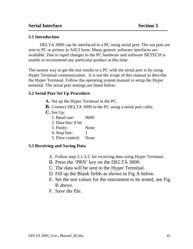
Serial Interface Section 3 3.1 Introduction
DELTA 3000 can be interfaced to a PC using serial port. The out puts are sent to PC or printer in ASCI form. Many generic software interfaces are available. Due to rapid changes in the PC hardware and software NETECH is unable to recommend any particular product at this time. The easiest way to get the test results to a PC with the serial port is by using Hyper Terminal communication . It is not the scope of this manual to describe the Hyper Terminal. Follow the operating system manual to setup the Hyper t al. The serial port settings are listed below: ermin
3.2 Serial Port Set Up Procedure
A. Set up the Hyper Terminal in the PC. B. Connect DELTA 3000 to the PC using a serial port cable. C. Set Up:
1. Baud rate: 9600 2. Data bits: 8 bit 3. Parity: None 4. Stop bits: 1 5. Flow control: None
3.3 Receiving and Saving Data
A. Follow step 3.1-3.2. for receiving data using Hyper Terminal. B. Press the ‘PRN’ key on the DELTA 3000. C. The data will be sent to the Hyper Terminal. D. Fill up the Blank fields as shown in Fig A below. E. Set the test values for the instrument to be tested, see Fig
B above. F. Save the file.
DELTA 3000_User_Manual_R2.doc 41
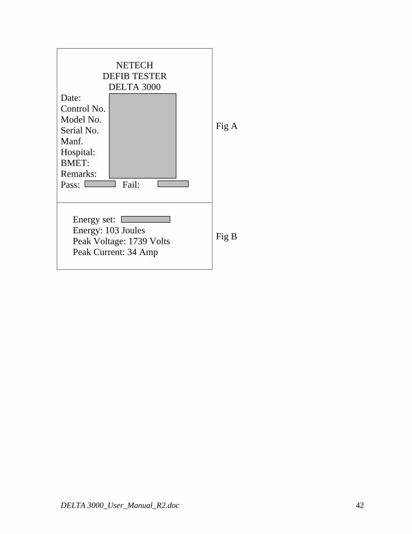
NETECH
DEFIB TESTER DELTA 3000
Date:
Control No. Model No. Serial No. Manf. Hospital: BMET: Remarks: Pass: Fail:
Fig A
Energy set: Energy: 103 Joules Peak Voltage: 1739 Volts Peak Current: 34 Amp
Fig B
DELTA 3000_User_Manual_R2.doc 42
Theory of Operation Section 4
4.1 Introduction
The DELTA 3000 Defibrillator Tester/ Pacer Analyzer / ECG Simulator is a precision, multi-purpose analyzer that performs tests on all defibrillators and all pacemakers. It is a microcontroller based design and utilizes sophisticated algorithms to control all system activities.
4.2 Defibrillator Output Measurement
The energy of the Defibrillator that is discharged into the 50 Ohm load of the Delta 3000 is calculated using the formula:
Energy E = [V2 (t)] /R. Where ‘V’ is the discharge Voltage across the load resistor ‘R’ and ‘t’ is the duration of the waveform in seconds.
The Delta 3000 measures the instantaneous voltage (attenuated by a factor of 2000/1.1), every 105 microseconds for a duration of 65 milliseconds. The Microcontroller computes the energy by summing up the squared voltages multiplied by the time and divides the product by 50 (load resistance).
The peak voltage measurement is performed by obtaining the largest value of the samples after a pulse measurement is recorded. The peak current is computed from the peak voltage divided by the load resistance of 50 Ohms.
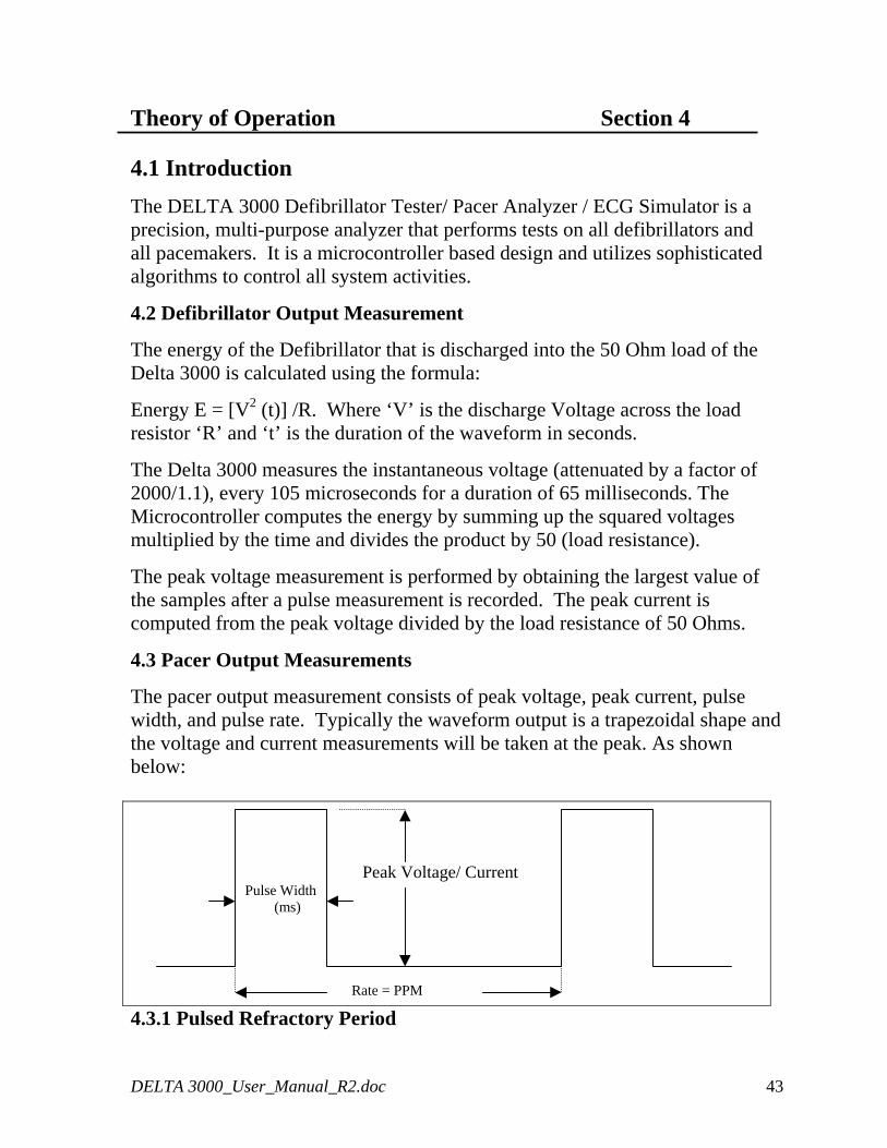
4.3 Pacer Output Measurements
The pacer output measurement consists of peak voltage, peak current, pulse width, and pulse rate. Typically the waveform output is a trapezoidal shape and the voltage and current measurements will be taken at the peak. As shown below:
Peak Voltage/ Current Pulse Width (ms) Rate = PPM
4.3.1 Pulsed Refractory Period
DELTA 3000_User_Manual_R2.doc 43
The pulsed refractory period is the time after a pulse is delivered from the pacemaker, during which the pacer will not detect cardiac activity. 4.3.2 Sensed Refractory Period
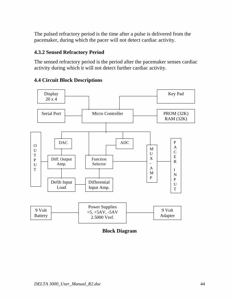
The sensed refractory period is the period after the pacemaker senses cardiac activity during which it will not detect further cardiac activity. 4.4 Circuit Block Descriptions
Micro Controller
Display 20 x 4
Function Selector
Key Pad
Serial Port PROM (32K) RAM (32K)
ADCDAC P A C E R I N P U T
Diff. Output Amp.
OUTPUT
Differential Input Amp.
MUX- AMP
Defib Input Load
Power Supplies +5, +5AV, -5AV
2.5000 Vref. 9 Volt Battery
9 Volt Adapter
Block Diagram
DELTA 3000_User_Manual_R2.doc 44
4.4.1 Defibrillator Input Load
The input load consists of two 25 Ohm 95 Watt 1% wire wound resistors that simulate the impedance of the human thorax under high voltage conditions.
4.4.2 Differential Input Amplifier
The Input amplifier performs a differential voltage measurement across the input load. The output of the amplifier is fed to the ADC and the scope output amplifier with a gain of 2. The discharge waveform is sensed by the ADC and sampled at the rate of 1000 times per second and saved in the memory. The captured waveform is time scaled to 1:200 and output through the D/A converter. The stored waveform can be observed through the paddles and the ECG leads.
4.4.3 Pacemaker Input Loads
Pacer inputs are selected via the function selector. There are two separate input loads for Atrial and Ventricular pacer inputs. The Transthoracic pacer inputs are connected to a fixed 50 Ohm load or a variable load. The multiplexer selects the appropriate input and feeds it to a differential amplifier which is then fed to the ADC via the function selector switch.
4.4.4 ECG Outputs
ECG and Arrhythmia waveforms are generated by the DAC and are available at the ECG leads, the High Level Output Jacks, and the Defib paddle contacts.
4.4.5 Power Supplies
The Delta 3000 is powered by two 9 Volt Alkaline batteries. The volt is converted into +5V, +5AV by low dropout linear regulators. The –5AV is generated by a charge pump regulator. The +5AV and –5AV is used to power the op amps and +5V is used for the digital circuits. A precision 2.5000 Voltage reference is generated from the 9 Volt source. The 2.5000 reference voltage is used for the ADC and D/A converters. The +5V regulator incorporates low battery detection and when the battery voltage is lower than 6.5Volt, it sends a low battery signal to the micro controller.
An external DC power jack is provided for use with the Netech AC adapter (PN: 302). When the AC Adapter is plugged into the DC jack the battery Voltage gets disconnected. 4.4.6 Key Pad
DELTA 3000_User_Manual_R2.doc 45
The Delta 3000 functions are controlled by the Menu and key interaction by the user. The 8 momentary Keys are used to control the function of the instrument. The Keys are directly interfaced with the Micro controller. When a key is pressed the micro controller responds by changing the appropriate menu on the display.
4.4.7 Display
The display is a 20 Character 4 Line LCD that interfaces directly with the micro controller. The contrast of the display is adjusted by a potentiometer.
4.4.8 Micro Controller Board
The Delta 3000 incorporates a 8XC55 based micro controller with 3 programmable timers and serial ports. The frequency of the crystal oscillator is 11.0598Mhz.
4.4.9 Memory
The memory consists of 32 K internal ROM, 32 K external ROM, and 32 K RAM. The internal and external PROM contains the software necessary to control the Delta 3000. The static RAM is used during program execution to hold buffers and stack operation.
4.4.10 Serial Port
The serial communications originates from the processor’s asynchronous port 0. The communications protocol is user configurable.
4.4.11 Analog to Digital Conversion
The input signals from the 50 Ohm load for the defib and the pacer input signals are routed through the selector switch to the ADC input. The ADC is a bipolar 13 bit (12 bit plus sign) successive approximation type with an auto calibration feature. The reference voltage is set at 2.5000 Volts by the precision reference.
4.4.12 Digital to Analog Conversion
The D/A converter is a dual 8 bit type. The reference of the first DAC is set at 2.5000 Volts precision reference. The waveform is generated by the second DAC whose reference voltage is controlled by the first ADC for scaling purposes (amplitude selections). The output signal is then offset and inverted by the Op amp to form a symmetrical signal with respect to ground. The signal is further scaled and buffered for the high level output. The single ended signal is amplified differentially and attenuated to 1mV (default amplitude) and fed to
DELTA 3000_User_Manual_R2.doc 46

the 50 Ohm load. This signal is sensed by the automatic defib to trigger the output pulse.
DELTA 3000_User_Manual_R2.doc 47
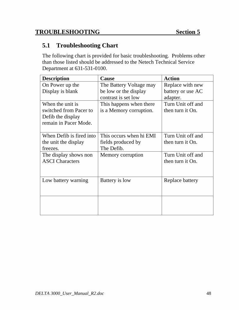
TROUBLESHOOTING Section 5
5.1 Troubleshooting Chart
The following chart is provided for basic troubleshooting. Problems other than those listed should be addressed to the Netech Technical Service Department at 631-531-0100.
Description Cause Action On Power up the Display is blank
The Battery Voltage may be low or the display contrast is set low
Replace with new battery or use AC adapter.
When the unit is switched from Pacer to Defib the display remain in Pacer Mode.
This happens when there is a Memory corruption.
Turn Unit off and then turn it On.
When Defib is fired into the unit the display freezes.
This occurs when hi EMI fields produced by The Defib.
Turn Unit off and then turn it On.
The display shows non ASCI Characters
Memory corruption Turn Unit off and then turn it On.
Low battery warning
Battery is low Replace battery
DELTA 3000_User_Manual_R2.doc 48

Appendix A Section 7
This page is intentionally left blank.
DELTA 3000_User_Manual_R2.doc 49