delta us en nr247 07.11.07 - advanced document ... pneumatic circuit: underpressure -0.6 bar...
TRANSCRIPT

Laminating machine DELTA (from prod. no. 247 and US from 1201)
- 2 -
CONTENTS
1. BASIC INFORMATION ...................................................................................... 5
1.1 Machine function and use .............................................................................. 5 1.2 Dimension scheme of the machine ................................................................ 5 1.3 Main and secondary place of operation ......................................................... 6 1.4 Machine process diagram .............................................................................. 6 1.5 Production plate ............................................................................................ 7
2. TECHNICAL PARAMETERS ................................................................................ 8
2.1 Input and output material ............................................................................. 8 2.2 Machine parameters ...................................................................................... 8 2.2.1 Output parameters...........................................................................................8 2.2.2 Electrical circuit ...............................................................................................8 2.2.3 Pneumatic circuit .............................................................................................8 2.2.4 Control system ................................................................................................8
2.3 Operation conditions...................................................................................... 8 2.4 Working mode................................................................................................ 8
3. MACHINE TRANSPORT AND MANIPULATION................................................... 9
4. MACHINE SCHEME AND SUBGROUPS LOCATION ........................................... 10
5. SAFETY RULES................................................................................................ 13
5.1 Manipulation and transport ......................................................................... 13 5.2 Machine installation..................................................................................... 13 5.3 General safety rules ..................................................................................... 14 5.4 Safety rules for electrical device.................................................................. 16 5.5 Disassembly and disposal ............................................................................ 16
6. TECHNICAL DESCRIPTION AND SUBGROUPS ADJUSTMENT.......................... 17
6.1 Feeder.......................................................................................................... 17 6.1.1 Safety rules for paper pile loading into the feeder.............................................17 6.1.2 Feeder function and description ......................................................................17 6.1.3 Front stacking bars ........................................................................................18 6.1.4 Side stacking bars..........................................................................................18 6.1.5 Feeding table ................................................................................................19 6.1.5.1. Feeding table movement .......................................................................................19 6.1.5.2. Feeding table drive ...............................................................................................19 6.1.5.3. Feeding defects and their elimination .....................................................................19
6.1.6 Feeding head ................................................................................................20 6.1.6.1. Safety rules for manipulation with feeding head......................................................20 6.1.6.2. Position of the feeding head ..................................................................................21 6.1.6.3. Separating elements adjustment ............................................................................21 6.1.6.4. Minimal format feeding..........................................................................................23 6.1.6.5. Feeding head protection against table hitting..........................................................23 6.1.6.6. Adjustment of paper releasing moment by suction cups ..........................................23 6.1.6.7. Sheet feeding defects............................................................................................24 6.1.6.8. Feeding head drive ...............................................................................................24

Laminating machine DELTA (from prod. no. 247 and US from 1201)
- 3 -
6.1.6.9. Overlap adjustment...............................................................................................24 6.1.7 Rollers and swing stops mechanism.................................................................24 6.1.7.1. Safety rules for adjustment of feeding rollers and swing stops .................................24 6.1.7.2. Function of 1st swing stops ....................................................................................25 6.1.7.3. Mechanism of rollers .............................................................................................25 6.1.7.4. Sheet inserting after having a gap..........................................................................28 6.1.7.5. Function of 2nd swing stops....................................................................................29
6.1.8 Adjustable guiding plates................................................................................29 6.1.8.1. Safety rules for adjustment of guiding plates ..........................................................29 6.1.8.2. Function of guiding plates .....................................................................................30
6.2 Compressor Becker T4.25 DSK..................................................................... 30 6.3 Main drive .................................................................................................... 31 6.4 Laminating unit............................................................................................ 31 6.4.1 Safety rules for zone of laminating roll and pressure roll....................................31 6.4.2 Laminating unit description.............................................................................33 6.4.3 Way of film loading ........................................................................................34 6.4.4 Laminating roll heating...................................................................................37 6.4.5 Required temperature setting .........................................................................38 6.4.6 Pressure mechanism ......................................................................................38
6.5 Separator ..................................................................................................... 39 6.5.1 Decurling bar.................................................................................................39 6.5.1.1. Safety rules for adjustment of the decurling bar......................................................39 6.5.1.2. Function of the decurling bar .................................................................................39
6.5.2 Pull rolls........................................................................................................40 6.5.2.1. Safety rules for pull rolls........................................................................................40 6.5.2.2. Function and adjustment of pull rolls......................................................................40
6.5.3 Cutting knives ...............................................................................................42 6.5.3.1. Safety rules for cutting knives................................................................................42 6.5.3.2. Function of cutting knives......................................................................................42
6.5.4 Snapping mechanism .....................................................................................44 6.5.4.1. Safety rules for the zone of the snapping roll ..........................................................44 6.5.4.2. Function of snapping mechanism ...........................................................................46 6.5.4.3. Speed control of snapping rolls ..............................................................................46 6.5.4.4. Snapping impulse setting / moment of first sheet separation ...................................46 6.5.4.5. Regulation of upper snapping roll position and its dropping down speed ..................47 6.5.4.6. The wave creating on paper in front of the snapping rolls .......................................47
6.6 Unloading device.......................................................................................... 48 6.6.1 Tilting unloading table....................................................................................49 6.6.2 Jogging table.................................................................................................50 6.6.3 Slow down conveyor ......................................................................................51
6.7 Other accessories......................................................................................... 51 6.7.1 Film slitter.....................................................................................................51 6.7.1.1. Safety rules for film slitter .....................................................................................51 6.7.1.2. Function and adjustment of slitter..........................................................................51
6.7.2 Perforator .....................................................................................................52 6.7.2.1. Safety rules for perforator .....................................................................................52 6.7.2.2. Function and adjustment of perforator ...................................................................52
6.7.3 Antistatic bar.................................................................................................52
7. THE WAY HOW TO START THE MACHINE ....................................................... 53
7.1 Description of control elements...................................................................53 7.1.1 Control panels ...............................................................................................53 7.1.2 Description of touch panel screens ..................................................................55

Laminating machine DELTA (from prod. no. 247 and US from 1201)
- 4 -
7.1.2.1. Main screen no. 1 .................................................................................................55 7.1.2.2. Alarms screen.......................................................................................................56 7.1.2.3. Main screen no. 2 .................................................................................................57 7.1.2.4. Main screen no. 3 .................................................................................................57 7.1.2.5. Service screen no. 1 – pneumatic rolls....................................................................57 7.1.2.6. Service screen no. 2..............................................................................................58
7.2 Getting the machine ready for job and its starting ...................................... 58 7.3 Elimination of defects during the lamination process.................................. 60 7.3.1 Wrinkles........................................................................................................60 7.3.2 Cross strip on the sheet..................................................................................61 7.3.3 Sheet separation between laminating and pull rolls...........................................61 7.3.4 Cut sheets.....................................................................................................61
8. MAINTENANCE ............................................................................................... 62
8.1 Safety rules for maintenance, adjustment and cleaning.............................. 62 8.1.1 Safety during the whole machine cleaning .......................................................62 8.1.2 Safety during the whole machine maintenance and adjustment .........................62 8.1.3 Safety during maintenance of the subgroups....................................................63 8.1.3.1. Feeding table........................................................................................................63 8.1.3.2. Drive ....................................................................................................................63 8.1.3.3. Belt drive of the snapping unit ...............................................................................63 8.1.3.4. Cutting knives.......................................................................................................63
8.2 Instruction for maintenance of subgroups .................................................. 64 8.2.1 Feeding table ................................................................................................64 8.2.2 Feeding head ................................................................................................64 8.2.3 Swing stops...................................................................................................64 8.2.4 Mechanism of rollers ......................................................................................64 8.2.5 Adjustable guiding plates................................................................................65 8.2.6 Main drive and the related ones ......................................................................65 8.2.7 Drive of 1st and 2nd swing stops and combined accelerating rollers ....................66 8.2.8 Standard maintenance of electrical device........................................................66 8.2.8.1. Electrical device cleaning .......................................................................................67 8.2.8.2. Electrical device inspection ....................................................................................67 8.2.8.3. Protective circuit inspection ...................................................................................67
8.3 Lubrication plan and check-up.....................................................................67
9. ERROR MESSAGES.......................................................................................... 69
9.1 Error / status indication and its elimination ................................................ 69 9.2 Errors not indicated by the control panel..................................................... 74
10. NOISE AND VIBRATION.............................................................................. 76
10.1 Emission of air spread noise ...................................................................... 76
11. EXPLOSIVE ENVIRONMENT ........................................................................ 77
12. SERVICE CENTRES ...................................................................................... 78

Laminating machine DELTA (from prod. no. 247 and US from 1201)
- 5 -
1. BASIC INFORMATION 1.1 Machine function and use
The purpose of laminating machine DELTA is thermal lamination of sheets. It is equipped with an automatic sheet feeder, a high-duty laminating unit and an accurate separator of pre-laminated sheets. The machine can be enlarged by a conveyor and a fixed tilting table or a jogging table according to customer’s needs. The feeder loads into the machine sheets of paper weight ranging from 115 g/m2 to 350 g/m2 ( 80 lb c1s – 14 pt). The overlap of inserted sheets is adjustable. Easy operation of the machine enables operator to control the speed and the temperature of the laminating process continuously. The laminated sheet of paper is unloaded onto an alternative unloading device after its separation from laminated sheets web. 1.2 Dimension scheme of the machine
Machine dimension EU US (length x width x height): 2630 x 1230 x 1410 mm 103,5 x 48,4 x 55,5 in. Floor space: 1.25 x 2.7 m 50 x 106 in. Ground plan: 3.3 m2 35,52 sq ft Machine weight: 860 kg 1895 lb Dimensions of transport pallet + machine: 1900 x 1450 x 1600 mm 74,8 x 57,1 x 63 in. Machine weight including transport pallet: 900 kg 1984 lb

Laminating machine DELTA (from prod. no. 247 and US from 1201)
- 6 -
1.3 Main and secondary place of operation
Only one person is enough to operate the machine. The main working place is in front of the control panel, from which is the ideal view on the whole machine.
1.4 Machine process diagram

Laminating machine DELTA (from prod. no. 247 and US from 1201)
- 7 -
1.5 Production plate

Laminating machine DELTA (from prod. no. 247 and US from 1201)
- 8 -
2. TECHNICAL PARAMETERS 2.1 Input and output material
Paper specification: EU US Max. paper format: 520 x 740 mm 20-1/2 x 29 in. Min. paper format: 200 x 200 mm 7-7/8 x 7-7/8 in. Paper weight: 115- 350 g/m2 80 lb c1s – 14 pt
Film specification: Suitable kinds of film: Polypropylene, Polyester, Nylon Film thickness: 24-45 µm 1 – 1,7 mil Inner diameter of film reel: 57-77 mm 2-1/4 x 3 in Outer diameter of film reel: 350 mm 14 in. 2.2 Machine parameters
2.2.1 Output parameters
Output / laminating speed: 3-30 m/min 10-98 ft/min (regard. technological conditions) Paper pile height of the feeder: 635 mm 25 in. Laminating temperature: according film producer 100 - 135 °C 212 – 302 °F Sheet overlap tolerance: ±2 mm 0,08 in. (at constant speed) Max. pressing force: 22,5 kN 4960 lb Max. linear nip pressure 43 N/m 240 lb 2.2.2 Electrical circuit
Power consumption: 7.5 kVA Machine voltage (basic variant): 3 x 400 V, 50 Hz (3xPE 208 – 240 60Hz) Control voltage of machine: 24 VDC Rated current: 18 A 27 A Recommended value of protection: 32 A 2.2.3 Pneumatic circuit
Pressure pneumatic circuit: 0.6 MPa; 130 l/min 90psi – 4,5 CFM Feeder pneumatic circuit: underpressure -0.6 Bar overpressure +0.6 Bar 2.2.4 Control system
PLC Mitsubishi series FX1N 2.3 Operation conditions
The machine was intended for smooth run under temperature conditions ranging from 5 °C (41°F) up to 40 °C (104°F). The acceptable air humidity level is from 30 % up to 70 %. The machine allocation should not be higher than 1000 m (3280 ft) above the sea level. It is not allowed to place the machine into explosive or dusty environment. 2.4 Working mode
The machine is intended for non-stop run.

Laminating machine DELTA (from prod. no. 247 and US from 1201)
- 9 -
3. MACHINE TRANSPORT AND MANIPULATION A wooden transport frame, which the machine is screwed to, is standardly used for machine transport from manufacturing plant to customer. The machine has to be transported in its working position with all parts assembled on it. It is necessary to prevent any damage of the machine during transport. The following picture shows the machine position on transport frame:
It is allowed to transport the machine including transport frame by means of lift truck or pallet trolley only! The length of lift truck fork has to reach by its further end at least behind transport supports of the machine. When taking the machine off the transport frame, the fixing screws should be removed first. Then move the lift truck in a way that its fork will get in between transport frame and machine frame. The following picture shows how to move the machine from transport frame onto room floor:

Laminating machine DELTA (from prod. no. 247 and US from 1201)
- 10 -
4. MACHINE SCHEME AND SUBGROUPS LOCATION
Feeder:
feeder
feeding head
separator
feeding table
compressor control panel
unwinding shaft laminating unit
feeding table guiding bar
feeding head
feeding table side stacking bars
roller chains
unwinding shaft
front stacking bars
feeding roll
torsion bar of table lifting
feeding table guiding bars

Laminating machine DELTA (from prod. no. 247 and US from 1201)
- 11 -
Feeding head:
Mechanism of feeding rollers and swing stops:
brushes
place for feeding head holding control elements
metal foils
metal foils
calliper foot
back stops
air-blowers
slide valve
Guiding of feeding head Overlap sensor
(sheet gap checking)
Weight rollers
Combined accelerating rollers
Capacity sensor
2nd swing stops Guiding plates Feeding roll
Regulation of guiding plates Side stacking bar
Holding plots
Regulation of accelerating rollers pressure
1st swing stops

Laminating machine DELTA (from prod. no. 247 and US from 1201)
- 12 -
Laminating unit:
Separator:
skewing wheel
unloading roll
cutting knives
decurling bar
snapping rolls
pull rolls locking lever of decurling bar
regulating screw of paper tension
Side regulation
Distributing roll Laminating roll Shaft support
Unwinding shaft
Unwinding brake
Film reel
Regulating screw of distributing roll

Laminating machine DELTA (from prod. no. 247 and US from 1201)
- 13 -
5. SAFETY RULES 5.1 Manipulation and transport
The machine has to be transported in its working position with all parts assembled on it. It is necessary to prevent any damage of the machine during transport. For safe transport and manipulation follow valid standards and regulations for manipulation with heavy loads. 5.2 Machine installation
Machine installation, its starting and operator’s training is made by Komfi service technician or other authorized company. The following conditions have to be achieved before installation:
even floor having the min. bearing capacity 25 kN/m2, (513 lb/sq ft) 0.6 MPa (90 psi) compressed air connection for pressure pneumatic circuit, connection 3 x 400 V / 230 V, 50 Hz (for US: 3xPE 208 – 240 60 Hz)and recommended value of protection 32 A for electrical circuit.
Compressed air connection: The main valve of compressed air has to be closed and no air inside the hose is allowed in a moment when the machine is being connected to compressed air supply. Power supply connection: The plug of flexible supply can be connected to socket of fixed supply only, which is checked regularly in compliance with relevant standards applicable in the user’s country. If the machine is not connected by means of the flexible cable, only experienced person (see standard EN 60204-1 Art. 3.52) is allowed to connect the machine to power supply – this means person with appropriate education and experiences, which enable him to avoid the danger and prevent risks, which electricity may cause. The initial inspection of the fixed supply according to IEC 364-6-61 has to be done before machine installation. It is allowed to run the machine only in the case, that electric cables at the customer’s and electro-supply to the machine meet all requirements of standards and regulations valid in the user’s country. The Becker Compressor: The Becker compressor supplying the machine feeder with air has its own power supply connection. ATTENTION!!! During the machine installation and before compressor getting in operation in the user’s premises, it is necessary to check direction of the compressor rotation! If the direction of its rotation is not the same as direction of the arrow marked on the cover, phases of power supply have to be changed! Only a trained technician is allowed to change it! Machine location: The machine should be located on a place with regard to the following distances: Distance between the unloading device and other object (wall) should be at least 0.5 m (20 in.) and distance between outer surface of the machine covers on drive side and other fixed object (another machine for instance) should be at least 1 m (40 in.) For comfortable machine operation it is recommended to keep distance of the laminating machine on operator side from other object approximately 1 m (40 in.)

Laminating machine DELTA (from prod. no. 247 and US from 1201)
- 14 -
ATTENTION! The machine is equipped with connector for joining an additional connecting conductor. This is because the value of leakage current from suppression components is higher than 3.5 mA AC. This connector for joining additional conductor is located on the crossbar between machine side plates. It is necessary to put on all the safety covers before machine starting! The machine can be run only in the case that electrical devices comply with all necessary rules and standards for machine starting valid in the user’s country. ATTENTION! It is necessary to make running-in of main drive before starting the machine for the first time after its delivery by the manufacturer. The running-in period is 30 hours. Do not work at maximal speed during the drive running-in! 5.3 General safety rules
1. The following standards were used during machine designing:
ČSN EN 292-1/2000 ČSN EN 292-2+A1/2000 ČSN EN 60204-1/2000 ČSN EN 1037/1997 ČSN EN 418/1994 ČSN EN 842/1997 ČSN EN 981/1998 ČSN EN 953/1998 ČSN EN 294/1994 ČSN EN 349/1994 ČSN EN 563/1996 ČSN EN ISO 11202/1997 ČSN EN 50081-2/1996 ČSN EN 61000-6-2ed/2002
2. Only a person who is duly trained by Komfi service technician or other authorized
company is allowed operate the machine. 3. The operator has to study operation manual first and needs to be sure he / she fully
understood all instructions before starting the machine. If there is something not clear enough, he / she should contact the manufacturer of the machine or other company authorized to make the installation.
4. It is allowed to use the machine for laminating of sheets of paper only. The machine
can not be used for any other job than it is destined for. The kind of film and processed paper should comply with conditions stated in chapter “Technical parameters”. There are control elements on the machine necessary for ensuring the lamination process. It is not possible to modify or change the control elements in any other way than it was adjusted by the manufacturer.
5. It is not allowed to do any activity on the machine (operation, adjusting, maintenace,
repairment, etc.) under influence of alcohol, drugs or certain medicaments, which could influence attention and abilities of the working person.
6. If the person doing any acitivity on the machine gets suddenly tired or sick, his / her
activity has to be interrupted immediately and the machine has to be stopped.

Laminating machine DELTA (from prod. no. 247 and US from 1201)
- 15 -
7. It is not allowed to touch the movable parts of the machine by fingers or other parts of body when the machine is running.
8. The operator’s working suit should be tight enough (eventually long hair combed in a
way) to prevent its catching by the movable parts of the machine. 9. Never clean any rolls (laminating roll, pressure roll, pull rolls, snapping rolls or other)
when the machine is running. If it is necessary to turn the rolls to enable its cleaning or check-up, use buttons “INCH” or “REVERSE”.
10. Never adjust any mechanisms during the machine run! The machine has to be stopped
first, than adjusted and even then started again. 11. Only a trained and entrusted person is allowed to adjust the machine. 12. The repairs and replacement of any parts of the machine should be done with the
machine main switch off. 13. The machine must be place on fixed and even floor. 14. The user will arrange lighting in the machine area with standard intesity for this kind of
work complying with standards and rules valid in the user´s country. 15. Use the buttons on the control panel always with one hand only. Take special care to
prevent catching any part of your body by the movable parts of the machine. 16. Do not put any objects on upper surfaces of the machine! 17. The machine is covered with both – fixed protective covers and movable protective
covers with safety position switch. 18. All covers have to be installed during the machine running! If all covers are not installed
or safety switches do not work properly, the machine can not be switched on and used! Never use the machine with open covers! Check, if all covers are installed and closed, before starting the machine!
19. It is not allowed to remove any cover during the machine run! 20. Check the function of all safety switches of the covers every day: the movable
protective cover of laminating roll, the movable protective cover of snapping rolls, the movable protective cover (door) of the inner space under the laminating and snapping unit. Check also if emergency stop buttons are working properly: one button on the control panel and one button on drive side of the laminating machine.
21. Take special care when manipulating with paper and during activities in the area of
tightened paper web with film – risk of cutting on the edge of paper! 22. Using the buttons “INCH” / “REVERSE” proceed as follows: 1. Keep the button “INCH” or “REVERSE” pushed until the roll reaches the requested position. Then release the button.
2. Wait until the machine stops after releasing the button “INCH” or “REVERSE”.

Laminating machine DELTA (from prod. no. 247 and US from 1201)
- 16 -
3. You can start cleaning the rolls or any other activity on the machine only after the machine stops definitely.
23. Take special care when regulating air pressure on treatment unit – risk of head injury
by hitting into inner parts of the machine! 5.4 Safety rules for electrical device
The electric installation complies with EN 60204-1:1997 regulation. Pursuant to this standard Art. 3.28, only a person instructed enough by a person experienced is allowed to operate the machine in order to prevent any danger and risks, which might be caused by electricity. Only an electrically skilled person (a person with relevant education and experiences) is allowed to work with electric device, i.e. repairs, adjustment and cleaning, according to EN 60204-1:1997 Art. 3.52 in order to prevent any danger and risks, which might be caused by electricity. It is not allowed to set any devices on the machine (especially end switches) out of operation or to modify any connections of the devices, which could change its function. All covers (in the contractor switch-board too) have to be put on their original place after finishing the job. The plug of flexible supply can be connected to the socket of fixed supply only, which is checked regularly in compliance with the relevant standards applicable in the user’s country. The initial inspection of the electrical device according to IEC 364-6-61, including the fixed supply (if the machine is not connected to flexible supply), is necessary to be done before the machine installation. It is allowed to run the machine only in the case that all requirements of standards and regulations valid in the user’s country, were reached on the electrical device. The user is obliged to fulfil all the requirements of standards and regulations valid in the user’s country for using the printing and related machines, especially for electrical devices, during the whole period of using the machine. The electric device was designed, produced and tested according to standard EN 60204-1:1997. The way of electrical installation of laminating machine is shown by drawing JF-41-100. Producer of the laminating machine DELTA guarantees, that the machine complies with the interference elimination to the limit according to EN 500081, part 1 – residential area, trade and light industry. 5.5 Disassembly and disposal
The machine does not contain any dangerous to life elements or fillings. Disassembly and disposal of the machine or its parts should be made according to standards and regulations for disposal or recycling of metal, plastic and synthetic material (ie. gear box oil) valid in the user’s country.

Laminating machine DELTA (from prod. no. 247 and US from 1201)
- 17 -
6. TECHNICAL DESCRIPTION AND SUBGROUPS ADJUSTMENT
6.1 Feeder
6.1.1 Safety rules for paper pile loading into the feeder
1. Never manipulate with paper pile when the machine is running! Your fingers might get jamed because of automatic movement of the feeding table.
2. The feeding table has to be in its lower position when loading the paper on it. To move the table to its lower position, push the button “STACK DOWN”. Be cautious when manipulating with paper pile on the table to prevent your head injury caused by feeding device.
3. To move the table to its working position, push the button “STACK UP”. 4. It is not allowed to touch the feeding table and its chain drive by means of fingers or other parts of body when the table is moving.
5. Be cautious at any manipulation under the feeding table plate to prevent your head injury caused by the feeding table frame.
6. Paper has to be loaded onto the feeding table in a right way: The paper pile should be pushed to the front stacking bars and located between the side stacking bars.
Be cautious during manipulation with paper!
6.1.2 Feeder function and description
The purpose of the feeder is continuous and accurate feeding of sheets of paper into the machine. The essential parts of the feeder are: feeding table, feeding head, front stacking bars, 1st swing stops, side stacking bars, feeding rollers (weight rollers and combined accelerating rollers) and 2nd swing stops. The feeding table is not removable and its purpose is stacking of sheets on it. The feeding table movement is arranged by means of roller chains and two guiding bars. The sheets are taken off the table and loaded into the machine by means of feeding head. The sheet feeding from the paper pile is done continuously during
ATTENTION! Feeding head elements!
ATTENTION! Table corner!

Laminating machine DELTA (from prod. no. 247 and US from 1201)
- 18 -
the laminating process. The feeding head calliper foot checks the height of the pile and controls a device for table lifting. The feeding table is lifted automatically according to the paper withdrawal from the pile. One step of table lifting is 2-3 mm (0,08 – 0,12 in.) for both full and empy table. The feeding table movement is controlled automatically by means of the feeding head or manually by means of buttons on main control panel: “STACK UP” – table goes up, “STACK DOWN” – table goes down. 6.1.3 Front stacking bars
The front stacking bars (a) together with the 1st swing stops (b) assure the right front position of paper pile on the feeding table. The sheets should be pressed closely to surface of the front stacking bars. Take care to prevent the sheets bending, which might cause problem during sheet inserting into the machine.
6.1.4 Side stacking bars
The function of side stacking bars (c) is making paper pile edges even. The side stacking bars are symmetrically adjusted regarding the machine centre. There should be a small gap / clearance (v) between the side stacking bars and the paper pile, so that the bars would not damage the paper or cause a wrong sheet inserting. The side stacking bars are controlled by means of control wheel (d) on operator side. The arrow (e) shows turning direction if the paper format is changed: for smaller format turn the wheel in minus direction, for bigger format turn the wheel in plus direction.
Attention! Check if the movement path of side stacking bars is free before moving them!
e d

Laminating machine DELTA (from prod. no. 247 and US from 1201)
- 19 -
6.1.5 Feeding table
6.1.5.1. Feeding table movement
Push the button “STACK UP” after paper pile has been loaded. The table (f) starts to lift up and its upper position will be set by means of capacity sensor (g). The capacity sensor has to be adjusted in a way, that the 1st swing stops (b) position is 6 mm (1/4 in) above the paper pile. Only a trained technician is allowed to adjust the capacity sensor. ATTENTION! The operator should watch the paper pile persistently during table lifting, because in case of capacity sensor (g) failure or wrong pile position out of sensor range, the paper pile could damage the feeding head.
6.1.5.2. Feeding table drive
The feeding table is suspended on roller chains (h) and is driven by means of electro-motor with gearbox (i). The chain is clamped to the table on both sides. The torque moment is transferred by means of torque bar (j), so that the movement crossing will not happen.
6.1.5.3. Feeding defects and their elimination
1. The table moves hardly even if there is no pile loaded on it: Check tightening of all chains and tighten them if necessary. Clean and oil the guiding bars of the feeding table too.
i j
h

Laminating machine DELTA (from prod. no. 247 and US from 1201)
- 20 -
2. The automatic table lifting is not working properly: Only a trained technician is allowed to eliminate this defect. Maintenance should be done in a way that functional parts are lubricated regularly according to lubrication plan and the parts are cleaned off grease and dust. 6.1.6 Feeding head
The feeding head lifts the sheets up from paper pile and loads them under the feeding roll. The feeding head position has to be changed when changing paper format. It is important to keep the following safety rules for safe manipulation with feeding head:
6.1.6.1. Safety rules for manipulation with feeding head
1. It is not allowed to hold the feeding head or to adjust it when the machine is running. The movement energy of suction cups might cause injury of your hands.
2. It is not allowed to manipulate with the feeding head if the machine is not stopped. The only exceptions are control elements. You can use the control elements during the machine run. Only a trained operator is allowed to manipulate with the control elements. The clothes of the operator should be tight enough to prevent its catching by the suction cups and pulling into the machine. Use one hand only for manipulation with the feeding head.
3. It is necessary to loosen the locking screw of the feeding head to enable feeding head movement. Proceed carefully during loosing it. The commotion when loosing this screw may cause a hand stroke into feeding head parts.
4. Hold the feeding head with both hands when moving it and move it along the linear guiding. Do not put your fingers close to the linear guiding – your fingers might be clamped between the trolley and stop in its end position.
5. Do not put any objects onto upper surface of the feeding head. 6. It is not allowed to remove the covers (the fixed cover of the feeding head and the fixed cover of the feeding head drive).
control elements

Laminating machine DELTA (from prod. no. 247 and US from 1201)
- 21 -
6.1.6.2. Position of the feeding head
Loosen the locking screw (a) on the feeding head guiding (n) and move the feeding head to its rear position (outwards the machine). Move the feeding table to its working position by pushing the “STACK UP” button. Move the feeding head to a position where the back stops (b) will slightly touch the rear edge of paper pile and then tighten the locking screw again.
6.1.6.3. Separating elements adjustment
The calliper foot (c) lies on paper pile. Move the metal foils (d) onto the paper pile, so that their front edge will exceed the paper edge by approximately 4-7 mm (0,16 – 0,17 in) and they are slightly laid down on paper pile in a moment of few sheets being taken out (before the table is lifted up being activated by means of calliper foot sensor). It is necessary to change the height of the metal foils (d) for various paper weights, so that the right sheet separation is ensured.
The brushes (e) should exceed the paper edge by approximately 2-3 mm (0,08-0,12 in) and they should touch the paper pile only slightly crossways from above, not to influence the
Metal foil Calliper foot
c d
Feeding head locking screw (a)
Place for feeding head holding
Linear guiding of feeding head (n)

Laminating machine DELTA (from prod. no. 247 and US from 1201)
- 22 -
sheet blowing. It is suitable to use only brushes instead of metal foils for paper of higher weight. Adjust the air-blowers (f) by means of a nut (g) in a way that upper 6 to 10 sheets are being blown from behind. The air blowers can not be placed too high, so that the air would blow over the top paper, which would disable right sheet inserting in time!
Adjust the underpressure needed for sucking the sheet by transport suction cups by means of regulator according to the kind of paper. The regulator is located on Becker compressor and the value of underpressure is shown on the manometer. The working underpressure is usually -0.4 bar (58 psi). It is recommended to adjust the underpressure when the paper is sucked to 4 suction cups. You can adjust the air pressure for blowing of sheets in pile, or specifically amount of air which is blown under the sheet being transported by suction cups. The adjustment is done by means of regulators (j and k). The pressure is set by the manufacturer for 0.4 bar (58 psi) and it is usually not necessary to change it.
You can adjust the step movement of paper pile to the 1st swing stops in automatic regime by means of regulator (l) – range of feeding table lifting height in automatic regime controlled by means of calliper foot.
e
e
j
g
k
b f
j k l

Laminating machine DELTA (from prod. no. 247 and US from 1201)
- 23 -
6.1.6.4. Minimal format feeding
It is necessary to turn the outer suction cups by 90° towards the laminating unit when feeding sheet format smaller than the outer suction cups (m) pitch. Loosen the screw (s) first. The suction cups are out of operation now and the sucking source is closed. The outer suction cups are out of operation:
m
6.1.6.5. Feeding head protection against table hitting
In the case of feeding head calliper sensor failure, it could happen that the feeding table will permanently lift up. To prevent table hitting into the feeding head, there is an induction sensor under supporting arm of the guiding bar of feeding head. This sensor has to be adjusted in a way, that it does not influence normal function of the feeding had and switches on in a moment of slight lifting of the feeding head when the table touches the head. The machine stops. For starting the machine again go down with the table and restart the machine.
6.1.6.6. Adjustment of paper releasing moment by suction cups
It is necessary to adjust the moment of paper releasing correctly and by this also the moment of paper sucking by means of suction cups to assure proper paper feeding. The adjustment is done by turning the slide valve (p). The releasing moment should be 3 mm before front dead centre of the suction cups which also specifies moment of suction. The suction cups are in their rear position in the moment of paper suction and start going down. The correct position of the slide valve is set by the manufacturer and is marked by a drilled hole in groove of the slide valve bushing. Only a trained technician is allowed to adjust it.
i - manometer
p – slide valve
m – outer suction cup
inner suction cups
s – screw
p

Laminating machine DELTA (from prod. no. 247 and US from 1201)
- 24 -
6.1.6.7. Sheet feeding defects
The reasons of sheet feeding defects may be: - The paper is not air conditioned. - The underpressure and pressure of the feeding head is not set correctly. - The sheets in paper pile are joined due to blunt knife cutting or they are sticked due to
printing ink not dry enough during printing process. It is necessary to shake the pile. - The side stacking bar is too tight. There should be a small gap between the paper pile
and the stacking bar. - The metal foils or brushes are not adjusted in a right way. - Too big gap between paper pile and back stops of feeding head. - The suction cups are stuck. Remove any dirt or sediments and clean the suction cups. - The suction cups are worn-out.
6.1.6.8. Feeding head drive
The feeding head is driven by means of belt drive of independent servo-motor. Only a trained technician is allowed to make any adjustments.
6.1.6.9. Overlap adjustment
It is necessary to change feeding head speed when changing the paper format. This is achieved by simple setting of values on the control panel touch screen. The input values are length of paper format and size of requested overlap. 6.1.7 Rollers and swing stops mechanism
6.1.7.1. Safety rules for adjustment of feeding rollers and swing stops
1. It is not allowed to manipulate with the roller mechanism (to insert or remove the weights) when the machine is running. There is a risk of your fingers clamping by the feeding roll.
2. The protective plexi-glass cover of the laminating roll has to be on when manipulating with the rollers.
3. Do not put your fingers or other part of your body close to the roller mechanism if the machine is running.
belt drive
feeding head
servomotor

Laminating machine DELTA (from prod. no. 247 and US from 1201)
- 25 -
4. When switching the machine off by means of the main switch, the mechanism of combined accelerating rollers is slightly lifted up spontaneously. Always switch the machine off by means of the main switch when adjusting the feeding rollers and the swing stops. If the nature of work does not allow adjusting the machine being switched off, it is necessary to be extremely cautious!
6.1.7.2. Function of 1st swing stops
The 1st swing stops (h) hold paper pile in a way that the front edge of the pile is upright. When the feeding head moves forwards the 1st swing stops go down to allow the paper being loaded into the machine. The swing stops are driven by means of pneumatic cylinder (i). The whole mechanism is set by the manufacturer and only trained technician is allowed to adjust it.
6.1.7.3. Mechanism of rollers
The rollers mechanism consists of weight rollers (a), combined accelerating rollers (b), i.e. joint weight and accelerating rollers, holding plots (c) and sheet overlap sensor (d).
h i

Laminating machine DELTA (from prod. no. 247 and US from 1201)
- 26 -
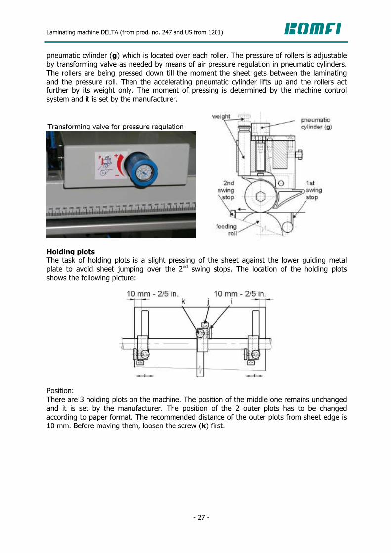
Weight rollers The weight rollers are in permanent touch with sheets of paper and they push the paper down to the feeding roll. Their position is adjustable according to the paper width. For processing paper of higher weight, it is suitable to increase the pressure against sheets by means of changing the weights. For this purpose a set of various weights is delivered together with the machine. You will change the weight (e) by simple taking it out or inserting.
Combined accelerating rollers For ensuring reliable sheet feeding it is important that the sheet which is waiting at the 2nd swing stops will immediately speed up to laminating speed at the moment of 2nd swing stops tilting down. The paper speed up is reached by increasing of rollers pressing force against the feeding roll. Pressing force of rollers is increased by means of pressurizing of
a
b
c
d
e a
Delivered set of weights:
Laminating machine DELTA (from prod. no. 247 and US from 1201)
- 27 -
pneumatic cylinder (g) which is located over each roller. The pressure of rollers is adjustable by transforming valve as needed by means of air pressure regulation in pneumatic cylinders. The rollers are being pressed down till the moment the sheet gets between the laminating and the pressure roll. Then the accelerating pneumatic cylinder lifts up and the rollers act further by its weight only. The moment of pressing is determined by the machine control system and it is set by the manufacturer.
Holding plots The task of holding plots is a slight pressing of the sheet against the lower guiding metal plate to avoid sheet jumping over the 2nd swing stops. The location of the holding plots shows the following picture:
Position: There are 3 holding plots on the machine. The position of the middle one remains unchanged and it is set by the manufacturer. The position of the 2 outer plots has to be changed according to paper format. The recommended distance of the outer plots from sheet edge is 10 mm. Before moving them, loosen the screw (k) first.
Transforming valve for pressure regulation

Laminating machine DELTA (from prod. no. 247 and US from 1201)
- 28 -
Pressing force: The pressing force depends on the bar holder movement (i). The screw (j) needs to be loosened first. Way of adjustment:
Insert 1 sheet of the requested paper weight into the machine. Move the plot so that it touches the paper but not deforms it. Tighten the screw (j).
ATTENTION! Move the holding plots first and then turn the control wheel for side stacking bars movement when changing the paper format to smaller one! Sheet overlap sensor The purpose of the sheet overlap sensor is to protect the supporting pressure roll against film sticking onto its surface. Check the function of this sensor every day after switching on the machine! Insert one sheet of paper in between the receiver and sender of photo-electric sensor SQ4 (d). Pull the sheet out. The machine should stop immediately and there should be an announcement “MISSING SHEET / GAP” on the control panel. Only a trained technician is allowed to repair the sensor.
6.1.7.4. Sheet inserting after having a gap
If a gap appears between the sheets, proceed as follows: 1. Move to service screen no. 1 on the touch screen and choose the possibility “2nd swing stop OFF” and “accelerating rollers OFF”.
2. Take a sheet of paper and insert it to the feeding roll and rollers.
d
Laminating machine DELTA (from prod. no. 247 and US from 1201)
- 29 -
3. Insert the paper to the previous sheet, so that it will lay over the first sheet at approximately the same distance as requested overlap is.
4. By pushing “START” button the machine runs and the function of accelerating rollers and 2nd swing stops is activated automatically.
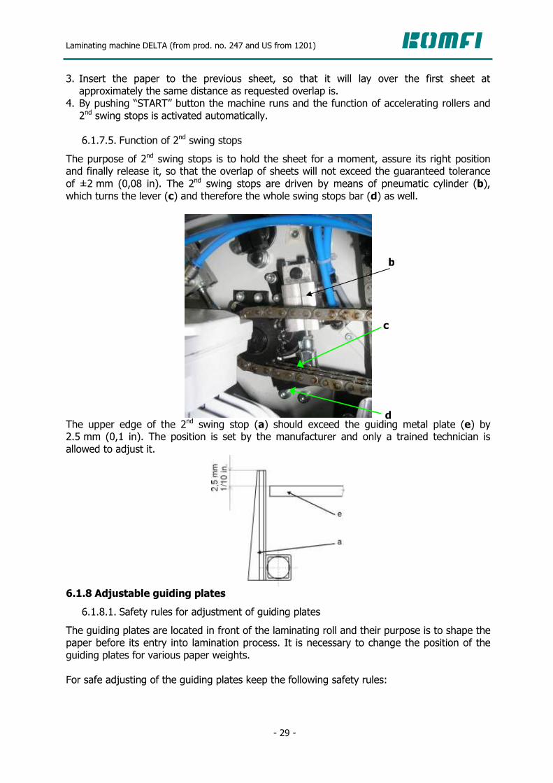
6.1.7.5. Function of 2nd swing stops
The purpose of 2nd swing stops is to hold the sheet for a moment, assure its right position and finally release it, so that the overlap of sheets will not exceed the guaranteed tolerance of ±2 mm (0,08 in). The 2nd swing stops are driven by means of pneumatic cylinder (b), which turns the lever (c) and therefore the whole swing stops bar (d) as well.
The upper edge of the 2nd swing stop (a) should exceed the guiding metal plate (e) by 2.5 mm (0,1 in). The position is set by the manufacturer and only a trained technician is allowed to adjust it.
6.1.8 Adjustable guiding plates
6.1.8.1. Safety rules for adjustment of guiding plates
The guiding plates are located in front of the laminating roll and their purpose is to shape the paper before its entry into lamination process. It is necessary to change the position of the guiding plates for various paper weights. For safe adjusting of the guiding plates keep the following safety rules:
c
d
b

Laminating machine DELTA (from prod. no. 247 and US from 1201)
- 30 -
To adjust the position of guiding plates by means of adjusting screw is allowed even if the machine is running. But only trained operator is allowed to adjust it! The clothes of the operator should be tight enough to prevent its catching by the swing stops or the feeding roll. Use only one hand for adjusting it and check if the laminating roll cover is closed.
6.1.8.2. Function of guiding plates
The purpose of the guiding plates (a) is elimination of paper wrinkling in a way, that the plates shape the paper before its entry under the laminating roll. Their position is adjusted by means of screw (b). Loosen the nut (c) first. It is necessary to lift the guiding plates up for processing paper of high weight, so that the paper is not shaped. On the other hand tilt the guiding plates down according to need for processing paper of low weight, so that the paper is shaped.
6.2 Compressor Becker T4.25 DSK
The laminating machine is equipped with compressor (rotary wing compressor Becker T4.25 DSK), which has its own technical documentation. This device works without any oil. It is necessary to prevent its sucking water, oil or other liquid. Do not place the compressor next to devices which blow out oil containing air. Set the initial underpressure value 0.4 Bar when connecting the compressor to the machine. Use the switch (a) for switching the compressor on / off during the machine adjustment.
The pressure valve as well as the vacuum valve should be adjusted only in a way which is neccessary for machine function. If the valve is tightened in its maximum level, the compressor works at its maximum capacity, which increases the cost for electricity and decreases its life time. Only a service technician is allowed to eliminate any defect of the
high paper weight: low paper weight:
a

Laminating machine DELTA (from prod. no. 247 and US from 1201)
- 31 -
compressor function. The compressor may be used only for purpose, which it was intended for (see the Pneumatic machine scheme). ATTENTION! It is necessary to check direction of compressor rotation during the installation and starting of Becker compressor! If the direction of its rotation is not the same as direction of the arrow marked on the cover, phases of power supply have to be changed! Only a trained technician is allowed to change it! 6.3 Main drive
The main drive and its distribution system is located under the cover on operator side of the machine. The distribution system is assured by means of roller chains. The operator is not allowed to access this area. Only a trained technician is allowed to remove the cover and to handle with this mechanism.
6.4 Laminating unit
6.4.1 Safety rules for zone of laminating roll and pressure roll
The working temperature of the laminating roll usually reaches 90-135 °C (194-3,2°F) depending on the kind of laminating film. Due to the proper function of the machine it is not possible to cover the area of the laminating roll and pressure roll completely, which is dangerous area: high temperature and access into a place, where both rolls work under big pressure. Regarding this it is necessary to keep strictly the following safety rules: 1. Never touch the hot laminating roll. 2. Never put your fingers or other part of your body close to the contact point of the
laminating roll and pressure roll, where is big pressure. 3. Use the functions “INCH” or “REVERSE” for cleaning. Never clean the surface of any roll
when the machine is running! 4. Check if your clothes are tight enough during the film loading or manipulation around
the laminating roll or the pressure roll, to prevent its catching by the moving rolls.
Main drive

Laminating machine DELTA (from prod. no. 247 and US from 1201)
- 32 -
5. Do not use any objects for cleaning the rolls or removing of film residues when the machine is running.
6. The plexi-glass cover of the laminating roll should always be closed if the machine is
running. It is not allowed to remove this cover or to modify it in any other way than it was set by the manufacturer.
7. Do not put any objects on upper part of the plexi-glass cover, which could deform the
cover or cover the ventilation holes. 8. Follow these instruction for inserting of first sheet of paper with film:
Insert paper with film in between the laminating and the pressure roll. Pull the sheet behind the laminating roll in a way, that the distance between your fingers and the laminating roll is at least 20 cm (7,8 in).
Push the button “PRESSURE CLOSE” to press the pressure roll. 9. It is not allowed to touch or to get close to the pressure roll levers in the area of
pneumatic cylinders or in the area between the pressure roll lever and the cover of screws of the laminating roll on operator side when switching the pressure roll on and off by means of “PRESSURE CLOSE” and “PRESSURE OPEN” buttons.
10. When opening the plexi-glass cover of the laminating roll, the cover has to be opened
completely so that it gets locked in its end position by means of flat spring. 11. Wait until the temperature on surface of the laminating roll gets bellow 50 °C for
maintenance or adjustment. Check the temperature of the roll on display if the machine is switched on. It is possible to check the temperature also by means of an external temperature measuring device. It is safe to do maintenance or adjustment after 60 min from the moment when laminating roll heating was switched off.
12. Do not touch the end part of film unwinding shaft when the machine is running! The
end part of the unwinding shaft can get hot at high speed of the machine and because of intensive reel breaking as a result of break friction. Take special care when replacing the film reel after long time run – risk of burning!
Laminating machine DELTA (from prod. no. 247 and US from 1201)
- 33 -
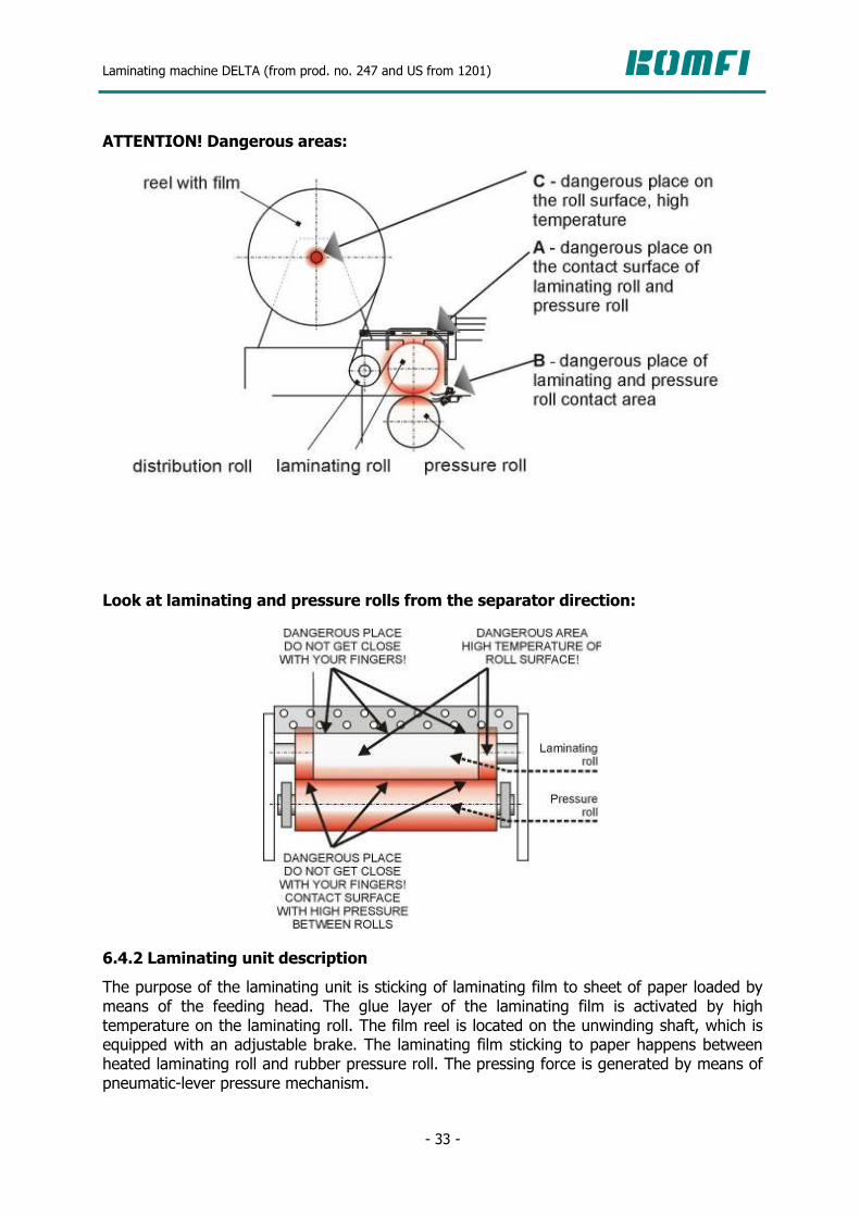
ATTENTION! Dangerous areas:
Look at laminating and pressure rolls from the separator direction:
6.4.2 Laminating unit description
The purpose of the laminating unit is sticking of laminating film to sheet of paper loaded by means of the feeding head. The glue layer of the laminating film is activated by high temperature on the laminating roll. The film reel is located on the unwinding shaft, which is equipped with an adjustable brake. The laminating film sticking to paper happens between heated laminating roll and rubber pressure roll. The pressing force is generated by means of pneumatic-lever pressure mechanism.

Laminating machine DELTA (from prod. no. 247 and US from 1201)
- 34 -
6.4.3 Way of film loading
1. Check the glued side of the film: One side of laminating film is covered with glue. To find out which side it is, proceed as follows: Visually – the side coated with glue is more matt. Placing a piece of film on the edge of the laminating roll – if glue is on upper side of the film, it will not get stuck to the roll
According to colour strip on a new film reel (the colour marking can differ according to film producer).
2. “Poly – out” or “Poly – in” The film reel loading onto the unwinding shaft depends on the side covered with glue. if the glue is on inner side – marking “Poly – in”, if the glue is on outer side – marking “Poly – out”.
3. Positioning of film reel on unwinding shaft: For loading of a new film reel of different width comparing to the previous one used on the machine, proceed as follows: Set the regulating nut (a) of the film side moving in a way, that its front edge will have the same position as mark on the reel shaft sleeve.
Loosen the M8 screw on the conic sleeve (d) on operator side, tilt the unwinding shaft supporting bar (f) and take the cone out of the unwinding shaft (b).
Move the tightening nut (e) on the conic sleeve on drive side back to its original position, which means as close as possible to the conic sleeve (c).
Check if the glued side of film is on outer or inner side. Load the film reel on the unwinding shaft according to the “POLLY IN” or “POLY OUT” scheme.
Put on the cone sleeve on operator side and slightly tighten the screw. Support the shaft with a supporting bar (f).
Set the conic sleeve (d) by its rear surface on the unwinding shaft in a way, that this surface will cover with “S” value on the unwinding shaft measurement (see picture below). You will find the “S” value on the measurement of side stacking bar (j).

Laminating machine DELTA (from prod. no. 247 and US from 1201)
- 35 -
Positioning of film reel with tube diameter 76 mm (3 in) by means of measurements:
If the film reel is positioned on unwinding shaft in this way, the film edge is moved inwards for 5 mm (1/5 in.) from the edge of paper. This setting is the most suitable for cutting knives function. If other distance is occassionally required, it is necessary to add the required difference to the “S” value!
Tighten the M8 screws on clamp connections of cone (d) and conic sleeve (c). Tighten the nut (e) properly against the cone on the conic sleeve on drive side so that film reel will not slip on the conic sleeves during the brake regulation.
Change the braking force of unwinding by means of the nut (g) according to reel weight and laminating speed.
Fine side adjustment of the film reel is possible by means of regulating nut (a). NOTE: Film reel positioning by means of measurements is vallid for reels with inner diameter of 76 mm (3”) only! For film reels of smaller inner diameter it is necessary to measure their position regarding paper with help of tape measure – distance from side plate and unwinding

Laminating machine DELTA (from prod. no. 247 and US from 1201)
- 36 -
shaft supporting bar (see the picture below). The reason is, that the cone is not inserted into the film reel in same distance as in case of reel diameter 76 mm (3 in) Positioning of film reel with tube diameter less than 76 mm, (3 in):
4. Sheet sticking onto beginning of the film: Stick a sheet of paper (of the same width as the sheets in the feeder) onto beginning of the film for easier film inserting into the machine. 5. Film loading Insert the film with sticked sheet around the distribution roll and over the laminating roll complying to the “Poly-out” or “Poly-in” scheme. Put the sheet through the gap between the laminating roll and the pressure roll, so that the paper gets at least 20 cm (3/4 in.) behind the contact point of both rolls. ATTENTION! Keep the safety rules for zone of the laminating roll and the pressure roll! 6. Sheet feeding by means of feeder Switch on the compressor and start the machine at minimum speed by pushing the button “START”. Stop the machine in a moment when the first sheet passes under the laminating roll and its front edge is at least 10 cm (3/8 in.)behind the contact point of the laminating and the pressure roll. All the time of loading the first sheet hold the film reel by hand to avoid the laminating roll pulling the film into the machine. 7. Pressing of the pressure roll up by means of the button “PRESSURE UP”

Laminating machine DELTA (from prod. no. 247 and US from 1201)
- 37 -
The “PRESSURE UP” button can be pushed only in the case that the sheet of paper from the feeder and the sheet of paper with film had passed through the rolls and your fingers hold the sheets at a minimum distance of 10 cm (3/8 in.) from the contact point of the laminating and the pressure rolls. 8. Loading of paper with film into the separator Check if the machine works at minimum speed first and then let 2 or 3 sheets pass throught the laminating unit. Cut the sheets manually and put the web of paper with film through the decurling bar and its roll first, then throught the pull rolls (being switched off) and finally through the snapping rolls. Tighten the sheet web by your left hand and switch on the “PULL ROLL” button into the “DOWN” position by your right hand. 9. Film tightening Check if the laminating film between film reel and laminating roll is evenly tightened all along its width after few sheets have run through the machine. If not, you can control it by the distribution roll axis deflection by means of regulating screw (k). ATTENTION! Keep the safety rules for zone of the laminating roll and the pressure roll! Film inserting through the whole machine:
6.4.4 Laminating roll heating
There is an electrical heating system which heats up the laminating roll. For optimal temperature regulation all along the roll length the heating elements are connected into 2 independently controlled units. The temperature range which the glue should be heated with is for each laminating film recommended by film producer. The temperature should be set with regard to the technological inputs of lamination process (kind of paper, kind of film or
Laminating machine DELTA (from prod. no. 247 and US from 1201)
- 38 -
even kind of ink used on printed matter). It is possible to use the whole range of the recommended temperature values for each film (for example 85-115 °C – 185-239°F). It could happen that paper of various thicknesses will require various temperature values for lamination process. 6.4.5 Required temperature setting
The required temperature is easily set by setting the numeric value on the touch screen (see the chapter 7.1.2.1). 6.4.6 Pressure mechanism
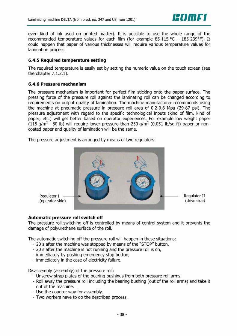
The pressure mechanism is important for perfect film sticking onto the paper surface. The pressing force of the pressure roll against the laminating roll can be changed according to requirements on output quality of lamination. The machine manufacturer recommends using the machine at pneumatic pressure in pressure roll area of 0.2-0.6 Mpa (29-87 psi). The pressure adjustment with regard to the specific technological inputs (kind of film, kind of paper, etc.) will get better based on operator experiences. For example low weight paper (115 g/m2 - 80 lb) will require lower pressure than 250 g/m2 (0,051 lb/sq ft) paper or non-coated paper and quality of lamination will be the same. The pressure adjustment is arranged by means of two regulators:
Automatic pressure roll switch off The pressure roll switching off is controlled by means of control system and it prevents the damage of polyurethane surface of the roll. The automatic switching off the pressure roll will happen in these situations: - 20 s after the machine was stopped by means of the “STOP” button, - 20 s after the machine is not running and the pressure roll is on, - immediately by pushing emergency stop button, - immediately in the case of electricity failure.
Disassembly (assembly) of the pressure roll: - Unscrew strap plates of the bearing bushings from both pressure roll arms. - Roll away the pressure roll including the bearing bushing (out of the roll arms) and take it out of the machine.
- Use the counter way for assembly. - Two workers have to do the described process.
Regulator I (operator side)
Regulator II (drive side)

Laminating machine DELTA (from prod. no. 247 and US from 1201)
- 39 -
6.5 Separator
6.5.1 Decurling bar
6.5.1.1. Safety rules for adjustment of the decurling bar
There is inner tension between the paper and the laminating film during the lamination process which may consequently cause bending of laminated sheets after their separation. By means of the decurling bar the sheets are straightened to avoid their bending. It is necessary to keep the following safety rules during the adjustment of the decurling bar position: 1. Proceed carefully when loosing the locking lever of the decurling bar: In the case of sudden loosing the groove on the regulating element could hit into the locking screw and the regulating lever could hit into your hand.
2. Proceed carefully when changing the position of the regulating lever: In the case of sudden change of the regulating lever position your hand could hit into the locking lever of the decurling bar.
3. Do not put your fingers close to the groove on regulating wheel when changing the position of the decurling bar.
6.5.1.2. Function of the decurling bar
The purpose of the decurling bar is making the paper straight after lamination process, which enables smooth pass of the sheets through the separator and consequently their easier stacking onto unloading device. The sheets are straightened when the sheet web is pulled over the decurling bar edge, which eliminates the inner tension of the paper. The intensity of sheets straightening is adjustable by decurling bar tilting in various angles. Decurling bar position with regard to the paper weight:
Regulating lever
Decurling bar
Locking lever

Laminating machine DELTA (from prod. no. 247 and US from 1201)
- 40 -
Paper straightening by means of the decurling bar helps stacking of the sheet onto the unloading table:
6.5.2 Pull rolls
6.5.2.1. Safety rules for pull rolls
1. Never get with your fingers or other part of your body close to contact point of upper and lower pull roll: your fingers can be jammed between the rolls.
2. The plexiglas cover of the pull rolls and the snapping rolls has to be closed always during machine run! This cover may not be dismantled or modified anyhow than it was done in the production plant!
3. When opening the plexiglas cover of pull and snapping rolls it is necessary to open it completely so that it gets locked in its end position by means of the flat spring!
6.5.2.2. Function and adjustment of pull rolls
The purpose of the pull rolls is creating tension on the paper web between the laminating unit and the snapping rolls, so that the sheet straightening by means of the decurling bar is enabled. The lower pull roll is driven by means of machine main drive and it has the same surface speed as the laminating roll. The upper rubber pull roll is placed on an excentric shaft, which enables lifting the roll up and paper web inserting through lower and upper pull rolls. The upper pull roll switching on / off is made by excentric shaft turning by means of lever and pneumatic cylinder. The position of the upper pull roll is controlled by operator turning the switch “PULL ROLLS” on / off.
Wrong unloading Right unloading
Unloading table Unloading table

Laminating machine DELTA (from prod. no. 247 and US from 1201)
- 41 -
Paper tension adjustment Paper tension can be changed by changing the gap between pull rolls by means of regulating screw. The size of gap between lower and upper pull roll is approximately marked on scale.
Examples: 1. Low paper tension: (The gap between the rolls is too big: 1 mm – 0,04 in)
2. High paper tension: (The gap between the rolls is too small: 0.1 mm – 0,04 in.)
Regulating screw
Locking nut
Yellow mark for manual setting
Scale of the upper pull roll position
Laminating machine DELTA (from prod. no. 247 and US from 1201)
- 42 -
6.5.3 Cutting knives
6.5.3.1. Safety rules for cutting knives
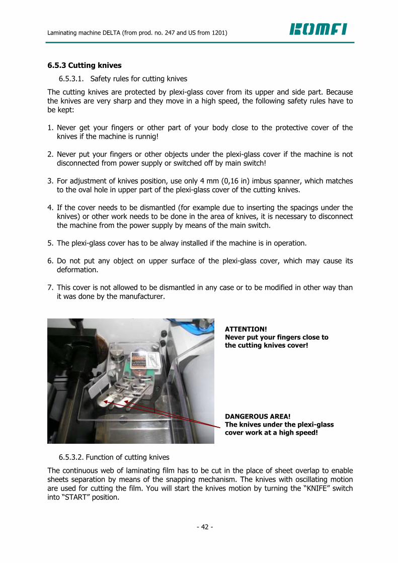
The cutting knives are protected by plexi-glass cover from its upper and side part. Because the knives are very sharp and they move in a high speed, the following safety rules have to be kept: 1. Never get your fingers or other part of your body close to the protective cover of the knives if the machine is runnig!
2. Never put your fingers or other objects under the plexi-glass cover if the machine is not disconnected from power supply or switched off by main switch!
3. For adjustment of knives position, use only 4 mm (0,16 in) imbus spanner, which matches to the oval hole in upper part of the plexi-glass cover of the cutting knives.
4. If the cover needs to be dismantled (for example due to inserting the spacings under the knives) or other work needs to be done in the area of knives, it is necessary to disconnect the machine from the power supply by means of the main switch.
5. The plexi-glass cover has to be alway installed if the machine is in operation. 6. Do not put any object on upper surface of the plexi-glass cover, which may cause its deformation.
7. This cover is not allowed to be dismantled in any case or to be modified in other way than it was done by the manufacturer.
6.5.3.2. Function of cutting knives
The continuous web of laminating film has to be cut in the place of sheet overlap to enable sheets separation by means of the snapping mechanism. The knives with oscillating motion are used for cutting the film. You will start the knives motion by turning the “KNIFE” switch into “START” position.
DANGEROUS AREA! The knives under the plexi-glass cover work at a high speed!
ATTENTION! Never put your fingers close to the cutting knives cover!

Laminating machine DELTA (from prod. no. 247 and US from 1201)
- 43 -
Position of knives with regard to the paper width:
Position of knives – look from the separator direction:
position of knives for narrow paper position of knives for wide paper Position of knives with regard to the edge of non-laminated part of paper:
Position of knives with regard to paper thickness: The knives height should be adjusted according to the laminated paper thickness. For this purpose a set of spacing plates under the knives is delivered together with the machine. Another alternative of knives adjustment for various paper weights is to deflect / tend the
paper
pull roll
knives
drive side
operator side
screw for position changing and locking

Laminating machine DELTA (from prod. no. 247 and US from 1201)
- 44 -
knives from / to the supporting pin (see the picture below). Nevertheless this method does not cover the whole range of used sheets and it is necessary to adjust the knives by means of spacing plates then.
6.5.4 Snapping mechanism
6.5.4.1. Safety rules for the zone of the snapping roll
Due to proper function of the machine it is not possible to cover the area of the snapping unit completely. This is the reason why the following safety rules should be strictly kept: 1. Never adjust the snapping rolls if the machine is running. The levers of the upper snapping roll are moving and it could happen that your fingers will be squeezed between the levers and the plexi-glass cover.
2. Never get your fingers or other part of your body close to contact point of the upper and the lower pull roll or the upper and the lower snapping roll.
3. The plexi-glass cover above the snapping roll has to be always closed during machine run! 4. When opening the snapping mechanism cover, open it completely so that it gets locked in its end position by means of the flat spring.
5. Do not put any objects on upper surface of the plexi-glass cover which may cause its deformation.
6. It is not allowed to dismantle the cover in any case or to modify it in other way than it was done by the manufacturer.
DANGEROUS AREAS OF THE SNAPPING MECHANISM (section through separator):

Laminating machine DELTA (from prod. no. 247 and US from 1201)
- 45 -
Regulating screws of snapping mechanism location:
The snapping mechanism is adjusted by the manufacturer and it is not necessary to handle the regulating screws during normal run.
The regulating screws are located under the separator cover The plexiglas cover has to be closed always when the machine is running!
ATTENTION! DANGEROUS AREA! Never get close with your fingers!

Laminating machine DELTA (from prod. no. 247 and US from 1201)
- 46 -
Skewing wheel for wave creating on the paper:
6.5.4.2. Function of snapping mechanism
The purpose of the snapping mechanism is separation of the laminated sheets of paper which are joined into a web by laminating film as a result of lamination process. The mechanism consists of upper and lower snapping roll, the gap between them is exactly defined: 1.5 mm (1/16 in.) on operator side and 2 mm (3/32 in)on drive side. The snapping process is assured by higher surface speed of snapping rolls in comparison with lamination speed. At the moment when sheet overlap appears behind the pull rolls, the upper snapping roll goes down onto the lower roll. Because of their higher speed comparing the lamination speed the sheets get separated. The upper snapping roll goes down on operator side (where the film is cut by means of knives) first and even then it goes down on drive side.
6.5.4.3. Speed control of snapping rolls
The surface speed of snapping rolls follows changes of laminating speed automatically. The optimal surface speed of snapping rolls is set in control system for 25 m/min (82 ft/min) higher than laminating speed. This value is reached in case that the turning driver for snapping rolls speed setting is in “Optimal” position marked with an arrow (see chap. 7.2). The operator can change the speed of snapping rolls during machine running ranging from 15 to 35 m/min (49,2 to 114,8 ft/min). The surface speed of snapping rolls is fixed set for 17 m/min (55,8 ft/min) in case of laminating speed reaching from 1 to 5 m/min (3,3 to 16,4 ft/min).
6.5.4.4. Snapping impulse setting / moment of first sheet separation
The moment of first sheet separation is set by operator on the control panel by pushing the “SNAP IMPULSE” button just at the moment, when the sheet overlap appears behind the pull rolls. The snapping moment is saved by the machine control system and separation of next sheets is automatic then. If operator does not manage to set the right snapping moment for the first time, the snapping impulse is canceled by pushing the “SNAP IMPULSE” button again. The operator can retry.
ATTENTION! DANGEROUS AREAS! Never get close with your fingers!
Skewing wheel for wave creating
Upper snapping roll

Laminating machine DELTA (from prod. no. 247 and US from 1201)
- 47 -
6.5.4.5. Regulation of upper snapping roll position and its dropping down speed
You can adjust a smaller gap between snapping rolls on operator side by means of different screwing in of the pneumatic cylinder piston rods. The speed of upper snapping roll drop down is adjustable according to laminating film kind and paper thickness. This is reached by changing the air flow through throttle valves on the pneumatic cylinders, which control dropping down of the upper snapping roll.
During regulation it is necessary to proceed in a way, so that the upper roll goes down on operator side (where the film is cut) first and even then on drive side.The snapping mechanism is adjusted by the manufacturer and it is not necessary to change this setting during normal run.
6.5.4.6. The wave creating on paper in front of the snapping rolls
It is suitable to create a wave on paper in front of the snapping rolls on drive side to enable easier and smoother sheet separation. Thanks to the wave the paper length is bigger on
sheet overlap
Throttle valves
Piston rod of pneumatic cylinders

Laminating machine DELTA (from prod. no. 247 and US from 1201)
- 48 -
drive side which enables easy and sequential sheet snapping after upper snapping roll drop down. The sheet is separated in direction from operator side (where the film is cut by means of knives) towards drive side dependent on sequential sheet pulling of the snapping rolls.
The wave is created by adjusting the skewing wheel on the edge of paper web on drive side. The right position of the skewing wheel is reached by its deflection in direction outwards machine. The slight turning of the wheel is usually sufficient.
6.6 Unloading device
The unloading device is located at the end of laminating machine and its purpose is to stack laminated sheets after their snapping by means of separator. The machine can be equipped with various unloading devices according to customer’s wish: tilting unloading table or jogging table. The machine can be delivered together with a slow down conveyor, which is placed between the machine and the unloading device.
Pressure adjustment
Lever for side adjustment locking
Skewing wheel Snapping rolls
Locking screw of wheel skewing

Laminating machine DELTA (from prod. no. 247 and US from 1201)
- 49 -
The right sheet unloading for different paper weights is arranged by regulation of air amount which blows under the paper from below and ensures paper transport to the front stop plate of table. The blowing direction is adjustable by turning the tube (d) by means of lever (e) and its intensity can be regulated by means of throttle valve (f).
6.6.1 Tilting unloading table
The tilting unloading table is mounted to the machine on one side and the opposite side is supported by adjustable foot. You can change the table position according to needs. 1. Adjustment of table unloading area according to paper format and weight:
The unloading table position is adjustable according to format of laminated sheet and thickness of the processed paper. The table modification is achieved by moving the side (a) and front (b) stop plates to requested distance by means of the screws (c). 2. The table height is adjustable in place of its clamping by means of two nuts, which gripe the butt hinge of the table plate:
d e f
a
b
c
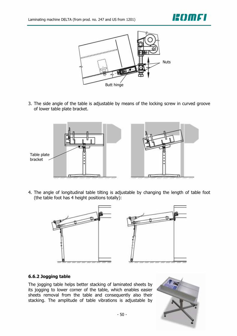
Laminating machine DELTA (from prod. no. 247 and US from 1201)
- 50 -
3. The side angle of the table is adjustable by means of the locking screw in curved groove of lower table plate bracket.
4. The angle of longitudinal table tilting is adjustable by changing the length of table foot (the table foot has 4 height positions totally):
6.6.2 Jogging table
The jogging table helps better stacking of laminated sheets by its jogging to lower corner of the table, which enables easier sheets removal from the table and consequently also their stacking. The amplitude of table vibrations is adjustable by
Nuts
Butt hinge
Table plate bracket
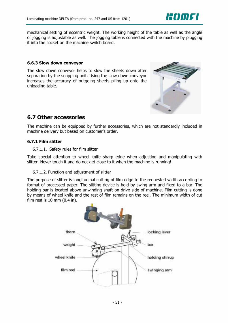
Laminating machine DELTA (from prod. no. 247 and US from 1201)
- 51 -
mechanical setting of eccentric weight. The working height of the table as well as the angle of jogging is adjustable as well. The jogging table is connected with the machine by plugging it into the socket on the machine switch board.
6.6.3 Slow down conveyor
The slow down conveyor helps to slow the sheets down after separation by the snapping unit. Using the slow down conveyor increases the accuracy of outgoing sheets piling up onto the unloading table. 6.7 Other accessories
The machine can be equipped by further accessories, which are not standardly included in machine delivery but based on customer’s order. 6.7.1 Film slitter
6.7.1.1. Safety rules for film slitter
Take special attention to wheel knife sharp edge when adjusting and manipulating with slitter. Never touch it and do not get close to it when the machine is running! 6.7.1.2. Function and adjustment of slitter
The purpose of slitter is longitudinal cutting of film edge to the requested width according to format of processed paper. The slitting device is hold by swing arm and fixed to a bar. The holding bar is located above unwinding shaft on drive side of machine. Film cutting is done by means of wheel knife and the rest of film remains on the reel. The minimum width of cut film rest is 10 mm (0,4 in).

Laminating machine DELTA (from prod. no. 247 and US from 1201)
- 52 -
ATTENTION! The wheel knife has to be placed coaxially with the film reel! You will fix the slitter position on the bar by means of locking lever. The pressure the wheel is pressed against the film reel is adjustable by number and size of weights inserted on thorn at the end of slitter arm. For getting the slitter out of operation, lift the arm and fix it into holding stirrup. 6.7.2 Perforator
6.7.2.1. Safety rules for perforator
Take special attention to perforating wheel edge when adjusting and manipulating with perforator. Never touch it and do not get close to it when the machine is running! 6.7.2.2. Function and adjustment of perforator
The purpose of perforator is film edge punching to ensure its subsequent snapping. The perforating wheel sits onto a film reel edge on operator side by its weight. You can set the perforator weight by means of inserting different number of weights on it according to weight of paper which is laminated. Proceed as follows when adjusting the perforator position: After setting position of film reel, loosen the locking lever of perforator. Lift the perforator arm up so that the teeth of perforating wheel were cca 2 mm (0,08 in) from edge of the reel.
Tighten the locking lever.
6.7.3 Antistatic bar
The purpose of antistatic bar is elimination of static electricity from the film. The antistatic bar can be located in front of or behind snapping rolls.

Laminating machine DELTA (from prod. no. 247 and US from 1201)
- 53 -
7. THE WAY HOW TO START THE MACHINE 7.1 Description of control elements
7.1.1 Control panels
There are 2 control panels on the machine. The location of all control elements on it shows the following picture:
PRESSURE ROLL PRESSED
LAMINATING ROLL HEATING
PAPER PILE UP MACHINE START
TOUCH SCREEN
PRESSURE ROLL RELEASED
MACHINE SPEED PAPER PILE DOWN MACHINE STOP

Laminating machine DELTA (from prod. no. 247 and US from 1201)
- 54 -
Except these elements there is also a second emergency stop button on drive side of the machine and a main switch which is located on the switch-board.
SWITCH ON / OFF COMPRESSOR BECKER
SNAPPING ROLLS SPEED
SNAPPING MECHANISM IMPULSE
PULL ROLLS PRESSED / RELEASED
SLOW RUN FORWARD / SLOW RUN BACK SWITCH ON / OFF SEPARATOR DRIVE
SWITCH ON / OFF KNIVES DRIVE
EMERGENCY STOP MACHINE ERROR SIGNALIZATION

Laminating machine DELTA (from prod. no. 247 and US from 1201)
- 55 -
7.1.2 Description of touch panel screens
The displayed data and control elements are split into various screens of touch panel according to their importance and with regard to illustration. Main screen no. 1 shows the most importanta data about machine run: announcements of machine status, laminating roll temperature, machine speed, format, sheet overlap, number of laminated sheets. You can set the laminating roll temperature and values of sheet overlap and paper format on this screen. Main screen no. 2 includes data and control elements, which are used less commonly: actual temperature on laminating roll ends, speed of separator motor, counter control. Main screen no. 3 shows the total amount of laminated sheets, number of working hours of the machine, numbers of PLC and HMI software versions and possibility to switch the language. Service screen no. 1 includes control elements, which may make the machine operation easier and check the function of controlled parts. Service screen no. 2 is intended for diagnosis of incremental sensor and for screen contrast setting. 7.1.2.1. Main screen no. 1
Main screen no. 1a:
Control of 1st swing stop + status indication. To enable swing stop control, it has to be in its upper position when the machine is stopped. Control of accelerating rollers
+ status indication
Control of 2nd swing stop + status indication
Temperature setting Status display Go to screen for setting format and overlap

Laminating machine DELTA (from prod. no. 247 and US from 1201)
- 56 -
Main screen no. 1b:
How to set the requested temperature: Evoke the panel with numeric buttons by touching in the area of requested temperature setting. Set the value of requested temperature and confirm by pushing „Enter“ button. The heating will be activated by switching on the “HEATING“ button to “START” position. Switch over to Alarms screen: Block for machine status announcements is a button for switching over to Alarms screen at the same time. Switch over to Alarms screen by touching the area for announcement status. You will switch back to Main screen no. 1 by touching any place in the text area.
7.1.2.2. Alarms screen
Difference between speed of main drive and separator (m/min)

Laminating machine DELTA (from prod. no. 247 and US from 1201)
- 57 -
7.1.2.3. Main screen no. 2
Principle of sheet counting: 1. Count up (switch “count up/down” is in ↑ position) The machine adds one sheet to the preset value with each snapping roll impulse. Reaching the number 99999 the counter sets to zero automatically. If you want to count from zero, set the preset value to 0. 2. Count down (switch “count up/down” is in ↓ position) The machine deducts one sheet fromt the preset value with each snapping roll impulse. The machine automatically stops when reaching the 0 value. The preset value is re-written to the sheet counter. You will start the machine by pusthing the “START” button again. 3. Sheet counter clearing You will zero the number of sheet by pushing the “RES” button on the touch screen.
7.1.2.4. Main screen no. 3
7.1.2.5. Service screen no. 1 – pneumatic rolls
Speed of separator drive (m/min) Count UP/DOWN
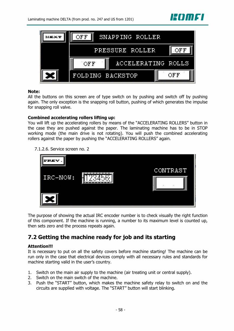
Laminating machine DELTA (from prod. no. 247 and US from 1201)
- 58 -
Note: All the buttons on this screen are of type switch on by pushing and switch off by pushing again. The only exception is the snapping roll button, pushing of which generates the impulse for snapping roll valve. Combined accelerating rollers lifting up: You will lift up the accelerating rollers by means of the “ACCELERATING ROLLERS” button in the case they are pushed against the paper. The laminating machine has to be in STOP working mode (the main drive is not rotating). You will push the combined accelerating rollers against the paper by pushing the “ACCELERATING ROLLERS” again.
7.1.2.6. Service screen no. 2
The purpose of showing the actual IRC encoder number is to check visually the right function of this component. If the machine is running, a number to its maximum level is counted up, then sets zero and the process repeats again. 7.2 Getting the machine ready for job and its starting
Attention!!! It is necessary to put on all the safety covers before machine starting! The machine can be run only in the case that electrical devices comply with all necessary rules and standards for machine starting valid in the user’s country. 1. Switch on the main air supply to the machine (air treating unit or central supply). 2. Switch on the main switch of the machine. 3. Push the “START” button, which makes the machine safety relay to switch on and the
circuits are supplied with voltage. The “START” button will start blinking.

Laminating machine DELTA (from prod. no. 247 and US from 1201)
- 59 -
4. It is recommended to clean the laminating and the pressure rolls before starting new job, especially if the laminated sheets have different format than those of previous job. The roll cleaning is recommended to be hot done – heat the laminating roll up (see chap. 7.1.2.1). Take special care when cleaning the laminating roll, because surface temperature of the roll ranges 90-135 °C (194-302 °F). Always use protective gloves complying the roll temperature and used cleansing articles when cleaning the laminating roll. Keep the safety rules for cleaning! (see chap. 8.1.1)
5. Adjust the side stacking bars according to the sheet width (see chap. 6.1.4). 6. Load paper pile onto the feeding table. 7. Measure the sheet distance from the machine side plate (see the picture).
8. Load the film reel and fix it in a way, that its position is 5 (1/5 in) mm from the paper edge. This distance is very important for right function of cutting knives!
9. It is suitable if the film width is 10 mm (0,4 in) smaller than width of the laminated sheet.
TAKE CARE OF MEASURING THE RIGHT DISTANCES! Read carefully the instruction for laminating film reel positioning (see chap. 6.4.3)! 10. Lift the feeding table up to its working position and move the feeding head to paper pile
so that the feeding head back stops are approximately 0.5 mm (0,02 in) from the paper pile (see chap. 6.1.6.2).
11. Set the paper format (sheet length) and requested sheet overlap (4 mm – 0,16 in) on the touch screen.
12. Set the requested laminating temperature on the touch screen according to kind of laminating film – gloss / matt (see chap. 7.1.2.1)
13. Stick a sheet of paper to the laminating film and load the film into the machine according to instructions in chap. 6.4.3.
14. Adjust the knives and insert the spacers under them with regard to the paper thickness (see chap. 6.5.3).
15. Set the turning driver of snapping rolls speed into “Optimal” positon 16. Switch on the Becker compressor. 17. Start the machine at the lowest speed. 18. Wait till the sheet fed by means of the feeding head gets under the laminating roll and
press the pressure roll up by means of button on the control panel.
distance: supporting bar – film distance: side plate - sheet

Laminating machine DELTA (from prod. no. 247 and US from 1201)
- 60 -
19. Insert the laminated sheet through the decurling bar and pull rolls to the separator. Switch on the pull rolls and separator motor buttons. It is possible to change the separator speed by means of potentiometer.
20. Tighten the laminated sheet web – switch of the pull rolls on the control panel, tighten the sheet web manually in direction of machine run and switch on the pull rolls again.
21. Switch on the cutting knives motor and move the knives over the sheet edge so that the knive cut the film (see chap. 6.5.3).
22. Before machine speed increasing, check and readjust if necessary: feeding head function, adjustment of metal foils, air blowers, right choice of weights on the feeding rollers, size of sheet overlap, angle of decurling bar tilting (see chap. 6.5.1.2) and right function of cutting knives (see chap. 6.5.3).
23. Set the impluse of sheets snapping by pushing the white button “SNAP IMPULSE” at the moment when the sheet overlap appears behind the pull roll (see the picture).
24. Set the skewing wheel behind the snapping roll (see chap. 6.5.4.6). 25. Check quality of lamination. If everything is OK, you can speed the machine up. 26. When the requested speed was reached you can change the speed of snapping rolls by
means of turning driver to achieve better snapping and less noise. The value of speed difference is shown on touch screen but only if the machine is running. If the machine is stopped, this value is not marked.
27. The machine will stop by pushing the “STOP” button. 7.3 Elimination of defects during the lamination process
7.3.1 Wrinkles
Possible reasons of above stated defects: Picture 1: - wet paper, - too tight brake of laminating film unwinding.
sheet overlap

Laminating machine DELTA (from prod. no. 247 and US from 1201)
- 61 -
Picture 2: - too high temperature of lamination, - wet paper, - too tight brake of laminating film unwinding, - too much tension on pull rolls.
Picture 3: - wrong setting of pressure roll pressure, - wrong setting of distribution roll, - wrong setting of upper pull roll stop, - wrong setting of pull roll eccentric bushing in the side plate on drive side, - the end zone of laminating roll does not heat (visible when laminating wide paper format).
Picture 4: - wrong setting of pressure roll pressure, - wrong setting of distribution roll, - loosen brake of laminating film unwinding, - the end zone of laminating roll does not heat (visible when laminating wide paper format),
- wrong setting of pull roll eccentric bushing in the side plate on drive side, - wrong setting of upper pull roll stop.
Picture 5: - too tight brake of laminating film unwinding, - ink or dirt on laminating or pressure roll.
Picture 6: - the laminating roll is not heated enough, - the laminating roll is overheated, - too much pressure, - loosened brake of laminating fiml unwinding.
7.3.2 Cross strip on the sheet
The cross strip appears because of wrong setting of decurling bar or in the case that during sheet separation the paper slips between the pull rolls. Check the position of decurling bar (see chap. 6.5.1.2) and increase the pull rolls pressure (see chap. 6.5.2.2). 7.3.3 Sheet separation between laminating and pull rolls
The reason of sheets being separated between laminating and pull rolls is too much tension on pull rolls. Decrease the pull rolls pressure (see chap. 6.5.2.2). 7.3.4 Cut sheets
If the gap between the knife sharp edge and supporting pin is too small, the sheets may be cut. Change the position of knives regarding the supporting pins. If it does not help, it is necessary to change the knives position by inserting the spacers (see chap. 6.5.3).
Laminating machine DELTA (from prod. no. 247 and US from 1201)
- 62 -
8. MAINTENANCE 8.1 Safety rules for maintenance, adjustment and cleaning
8.1.1 Safety during the whole machine cleaning
1. It is not allowed to clean any part of the machine when it is running. 2. If the cleaning requires turning of the rolls into a different position, use the buttons “INCH” and “REVERSE”:
a) Keep the “INCH” or “REVERSE” button pushed until the roll reaches the required position. Then release the button.
b) Wait until the machine stops definitely. c) It is not allowed to start the cleaning or other work on the machine sooner that it
stops definitely. 3. Take special attention to cleaning of the laminating roll because the temperature on the roll surface is 90-135 °C. Always use protective gloves when cleaning the laminating roll with regard to the roll temperature and used cleaning articles.
4. Do not use aggressive solvents for cleaning of rubber rolls, because it could cause injury or damage of the rubber surface.
5. It is not allowed to push the button “PRESSURE UP” if the operator’s hands are close to the pressure roll when cleaning the machine.
8.1.2 Safety during the whole machine maintenance and adjustment
1. It is not allowed to remove any covers if the machine is running. 2. Do not start the machine if some of the covers are dismantled. 3. Any maintenance or adjustment can be done only if the main switch is off and secured. 4. Wait until the temperature on the surface of the laminating roll gets bellow 50 °C (122 °F) for maintenance or adjustment. Check the temperature of the roll on the display if the machine is switched on. It is possible to check the temperature also by means of an external temperature measuring device. It is safe to do the maintenance or adjustment after 60 min from the moment the laminating roll heating was switched off.
5. The clothes of the operator has to be tight enough (eventually long hair combed in a way) to prevent its catching by the movable parts of the machine during the maintenance or adjustment.
6. Use only high quality and proper tools for maintenance and adjustment: risk of injury when using for example damaged tools.
7. Use the eye protective shield when putting on the springs. 8. Only a trained and responsible person is allowed to make any maintenance and adjustment.

Laminating machine DELTA (from prod. no. 247 and US from 1201)
- 63 -
8.1.3 Safety during maintenance of the subgroups
8.1.3.1. Feeding table
The feeding table moves up in steps in the automatic mode. You can move it manually as well when loading a new paper pile. It is necessary to keep the following safety rules for safe work: 1. Only a trained and responsible person is allowed to handle the mechaism of the feeding table lifting.
2. Use only “STACK UP” and “STACK DOWN” buttons for the table movement.
8.1.3.2. Drive
The main drive is located on the opposite side from the operator under a fixed protective cover and it drives the feeding roll, the laminating roll and the pull rolls. For safe work is necessary to keep the following safety rules: 1. It is necessary to swich off the compressed air supply for adjustment of 1st and 2nd swing stops mechanism and the pressure rollers.
2. Only a trained and responsible person is allowed to handle the main drive mechanism.
8.1.3.3. Belt drive of the snapping unit
The belt drive is located on the opposite side from the operator under the fixed protective cover of the separator. 1. The machine has to be disconnected from the power supply by means of the main switch for tightening the belt.
2. Only tightening of the belt is allowed during the drive maintenance. Any other work has to be arranged by a service technician.
8.1.3.4. Cutting knives
The knives have very sharp edge and that’s the reason why the following safety rules have to be strictly kept: 1. It is not allowed to touch the knives on the sharp side during their adjustment or maintenance. Hold the knives only in a non-sharp place.
2. Put the knives on a safe place outside the machine while handling them, so that nobody can be injured.

Laminating machine DELTA (from prod. no. 247 and US from 1201)
- 64 -
3. The protective plexi-glass cover has to be installed for testing of newly installed knives or even the original ones.
4. Use only the 4 mm imbus spanner for adjustment of the knives position, which will match to the oval holes in the upper part of the plexi-glass cover.
8.2 Instruction for maintenance of subgroups
8.2.1 Feeding table
The feeding table is suspended on two roller chains and it is guided along two guiding bars. Only the replacement or tightening of the roller chains is allowed to be done during maintenance. It is not necessary to remove the fixed protective covers for chains tightening. There are tightening screws on the feeding table frame for the chain tightening.
Napínacíšroub
For the chain replacement, proceed as follows:
Remove the fixed protective covers. Disconnect the chain from the tightening screws. Remove the old chain. Put on the new one. Connect the chain to the tightening screws and tighten the chains in a way that the table is lifted evenly with regard to the floor.
Install the fixed protective covers. 8.2.2 Feeding head
The feeding head does not require a special way of maintenance. 8.2.3 Swing stops
The swing stops do not require a special way of maintenance. Only a service technician is allowed to do the assembly and disassembly. 8.2.4 Mechanism of rollers
The mechanism of rollers does not require a special way of maintenance. Only a service technician is allowed to do the assembly and disassembly.
Tightening screw
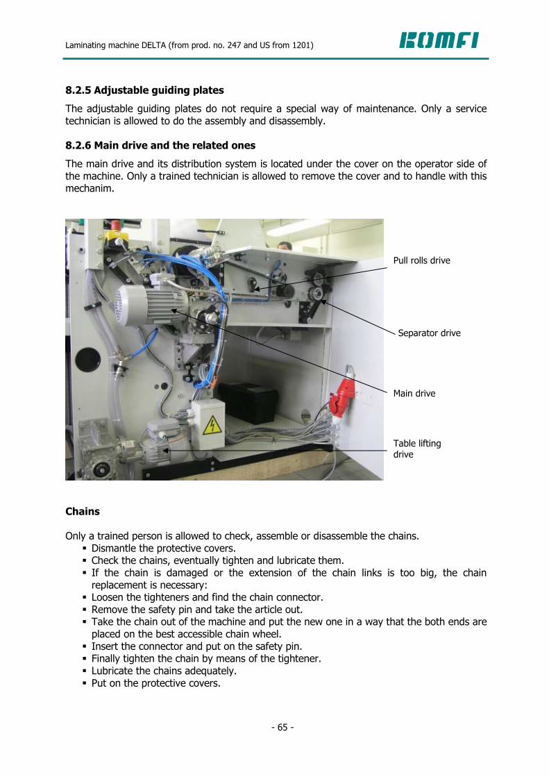
Laminating machine DELTA (from prod. no. 247 and US from 1201)
- 65 -
8.2.5 Adjustable guiding plates
The adjustable guiding plates do not require a special way of maintenance. Only a service technician is allowed to do the assembly and disassembly. 8.2.6 Main drive and the related ones
The main drive and its distribution system is located under the cover on the operator side of the machine. Only a trained technician is allowed to remove the cover and to handle with this mechanim.
Chains Only a trained person is allowed to check, assemble or disassemble the chains.
Dismantle the protective covers. Check the chains, eventually tighten and lubricate them. If the chain is damaged or the extension of the chain links is too big, the chain replacement is necessary:
Loosen the tighteners and find the chain connector. Remove the safety pin and take the article out. Take the chain out of the machine and put the new one in a way that the both ends are placed on the best accessible chain wheel.
Insert the connector and put on the safety pin. Finally tighten the chain by means of the tightener. Lubricate the chains adequately. Put on the protective covers.
Separator drive
Main drive
Pull rolls drive
Table lifting drive

Laminating machine DELTA (from prod. no. 247 and US from 1201)
- 66 -
Belt Only a trained person is allowed to assemble or disassemble the belt.
Dismantle the protective cover. Check the belt. Eventually adjust the tightening force by means of adjusting screw of spring. If the belt is damaged, its replacement is necessary. The type of the used belt is stated in the catalogue or it is printed on the upper surface of the belt itself.
Loosen the tightener spring by means of adjusting screw. Change the belt. Modify the tightener force by means of adjusting screw of spring so that the belt will not jump over the belt pulley teeth at maximum snapping speed.
Put on the protective cover. 8.2.7 Drive of 1st and 2nd swing stops and combined accelerating rollers
The drive of the 1st and 2nd swing stops and the accelerating rollers is located under the fixed protective cover on the opposite side of the operator and it is assure by means of the pneumatic cylinders. Only replacement of the pneumatic cylinders or solenoid valves can be done during maintenance. During the maintenance proceed as follows:
Remove the fixed protective cover. Replace the defective parts. Install the fixed protective cover again.
8.2.8 Standard maintenance of electrical device
Only instructed person (see the standard ČSN EN 60201-1 Art. 3.52) is allowed to do the maintenance of the electrical device, which means a person instructed enough by a person experienced in order to prevent any danger and risks, which might be caused by electricity.. The standard maintenance of the electrical device means the check-up and cleaning of the electrical elements of the machine. It is recommended to do the standard maintenance always after reaching a certain number of processed sheets or after a certain running time of the machine according to the instructions of the KOMFI service technician. It is also recommended to keep records about the maintenance or provided service work which could be a usefull help in the case of next maintenance or repairs. The machine has to be disconnected from the power supply by removing the cable from the plug or by any other appropriate way before starting any work on the electrical device.
Pneumatic cylinders

Laminating machine DELTA (from prod. no. 247 and US from 1201)
- 67 -
8.2.8.1. Electrical device cleaning
Clean all the electrical elements on the machine and the switch board during the regular inspections. You can use the compressed air (if it is available) for cleaning dust. If there is still some dirt, wipe it. Clean the feeding head sensor at least once in 2 weeks.
8.2.8.2. Electrical device inspection
The fixation of the devices and their terminals tightening should be checked by the inspection. Tighten the connection if necessary. Pay special attention to the tightening of the contractor terminals. The insulating resistance between the power circuit cables and the protective circuit measured at 500 VDC can not be less than 1 MΩ .
8.2.8.3. Protective circuit inspection
The tightening of protective cables connection should be checked by the inspection. Tighten the connection if necessary. The circuit continuity is being checked by connecting to the PELV source of current of min. 10 A at 50 Hz for at least 10 s. The test is done between the the PE terminal and various points, which are parts of the protective circuit (see ČSN EN 60204-1 Art.19.2). The voltage measured between the PE terminal and the testing points should not exceed these values: U = 3.3 V pro S = 1.0 mm2 U = 2.6 V pro S = 1.5 mm2
U = 1.9 V pro S = 2.5 mm2
U = 1.4 V pro S = 4.0 mm2
U = 1.0 V pro S > 6.0 mm2
where: U = the maximal measured voltage decrease S = the minimal effective cut of the protective cable of the tested sub-circuit. The frequency of measuring of the protective circuit continuity complies with the requirements of the appropriate standards and rules valid in the user’s country. 8.3 Lubrication plan and check-up
It is necessary to lubricate and check the machine parts regularly, so that the right function of the machine is reached and its life time is increased. Daily: 1. Check the amount of condensate in the air treating unit (if the condensate level in the tank is more than 20 mm, it is necessary to be removed).
2. Check if all the covers are installed and no screw on it is missing or loosen. 3. Check the right function of these sensors:
- end switches of the feeding table, - capacity sensor, - sensor for the feeding head protection, - checking sensors of the movable covers, - emergency stop button.

Laminating machine DELTA (from prod. no. 247 and US from 1201)
- 68 -
Once in two weeks: 1. Clean and lubricate with liquid oil (or treat with spray) all sliding travels and guiding bars. 2. Clean and oil the guiding rollers. Once in a month: 1. Tighten and lubricate all the roller chains. 2. Clean and lubricate the guiding rollers 3. Check and eventually tighten all chains and belt. 4. Check and clean the pneumatic drives of swing stops, accelerating rollers and upper snapping roll.
The gearboxes of the main drive and the feeding table lifting: Running-in time of the main drive: 30 h (Do not operate at maximum output during the running-in time!) The MRT gearboxes are filled with long-life systhetic oil, type ISO VG 320. The gearboxes are not equipped with filling screws, drain screws or level gauge. The main drive MRT 50: 0.13 l (4 oz) of oil Table lifting drive MTA 63/50: 0.04 + 0.13 l (1 + 4 oz) of oil In the case of necessity to change or add the oil, use the same type of the oil only! Do not use the mineral oil in any case!

Laminating machine DELTA (from prod. no. 247 and US from 1201)
- 69 -
9. ERROR MESSAGES 9.1 Error / status indication and its elimination
The machine error is indicated by the yellow light sensor “ERROR” twinkling and announcing the error or status on the right upper part of the control panel. You will move to Alarms screen by touching the mentioned part of panel, where the error or status is described in more details. It is necessary to reset the error status after elimination of error cause - this by means of pushing “START” button. Push the “START” button once again to run the machine. Error – Safety relay deactivated Alarms screen: Cover, Emergency stop Safety relay Elimination:
Check the switching on position of the both emergency stop buttons. Close all the covers on the machine. Switch on the safety relay by pushing the “START” button. If the safety relay is not switched on by pushing the “START” button and even not after the previous activities, the error is probably caused by electric connection (i.e. disconnected cable). See the electrical connection scheme of the safety relay circuit.
Error – Temperature regulator alarm - centre Alarms screen: Laminating roll is overheated – MIDDLE Check heating circuit. Elimination:
Check the actual temperature value of the laminating roll on the control panel. If the temperature is higher than the limit value (165 °C – 329 °F), the reason is probably the crashed semi-conductor relay A1. Change it – see the scheme of the laminating roll heating circuit.
The error is eliminated after the temperature of the middle part of the laminating roll decreasing below the maximal limit (165 °C – 329 °F).
Error – Wrong phase sequence Alarms screen: Wrong phase sequence of power supply Elimination:
Stop the machine. Change the phase sequence of the power supply. Switch on the machine.
Error – Gap between the sheets Alarms screen: Gap between the sheets. Check the sheets overlap. Elimination:
Check the gap between the sheets. Prevent the film sticking to the pressure roll. Quit the error by pushing the “START” button. Start the machine by pushing the “START” button.

Laminating machine DELTA (from prod. no. 247 and US from 1201)
- 70 -
Error - Fuse FU11 disconnected Alarms screen: Circuit protected by fuse FU11 is not live. Elimination:
Check the fuse FU11 in the switch-board and change it if it is disconnected. If the fuse is ok, check the connection of the circuit protected by fuse FU11, which should have a voltage of 24 VDC.
Error - Fuse FU12 disconnected Alarms screen: Circuit protected by fuse FU12 is not live. Elimination:
Check the fuse FU12 in the switch-board and change it if it is disconnected. If the fuse is ok, check the connection of the circuit protected by fuse FU12, which should have a voltage of 24 VDC.
Error – Feeding head protection Alarms screen: Feeding head protection sensor Push FEEDER DOWN Elimination:
Check the position of the feeding head and if it is deflected by the paper pile move the pile into the right position.
Quit the error status by pushing the “START” button. Move the feeding table to its lower position by pushing the button “STACK DOWN”. Check the connection of the feeding head protection sensor SQ6 according to the electrical scheme.
Error - FA1 breaker for U1 frequency convertor switch off Alarms screen: Main drive circuit breaker. Check circuit Elimination:
Check the FA1 breaker in the switch-board. Switch the breaker on to position I. If the control panel still announces error, it is necessary to check the circuit protected by FA1.
Error – Temperature regulator alarm - edges Alarms screen: Laminating roll is overheated – end sides. Check heating circuit Elimination:
Check the actual temperature value of the laminating roll edges on the control panel, Main screen no. 2. If the temperature is higher than the limit value (165 °C – 329 °F), the reason is probably the crashed semi-conductor relay A1. Change it – see JF-41-100/a page 4.
The error is eliminated after the temperature of the laminating roll edges decreasing below the maximal limit (165 °C – 329 °F).
Laminating machine DELTA (from prod. no. 247 and US from 1201)
- 71 -
Error – temperature sensor Pt100 disconnected - heating, middle Alarms screen: Temperature sensor is disconnected – middle Elimination:
Possible problem with disconnection of cables or with connector connection of cables of temperature sensor on operator side. Fix it.
Possible problem with Pt100 - BT1 sensor. Replace it. Note: To check this sensor preliminary, the resistance of this sensor at 25 °C temperature is approximately 110 Ω.
The error is eliminated only in the moment that the BT1 temperature sensor shows the correct temperature. You can extinguish the error by switching off the heating by means of the “HEATING” switch on the control panel to its “STOP” position.
Error – temperature sensor Pt100 short-circuited – heating, middle Alarms screen: Short circuit of temperature sensor - middle Elimination:
Possible problem with cable connection or with connector connection of cables of temperature sensor on operator side. Fix it.
Possible problem with Pt100 - BT1 sensor. Replace it. Note: To check this sensor preliminary, the resistance of this sensor at 25 °C temperature is approximately 110 Ω.
The error is eliminated only in the moment that the BT1 temperature sensor shows the correct temperature. You can extinguish the error by switching off the heating by means of the “HEATING” switch on the control panel to its “STOP” position.
Errorr - Pt100 temperature sensor disconnected – heating, edges Alarms screen: Temperature sensor is disconnected – end sides Elimination:
Possible problem with cable disconnection or with connector connection of the cables of the temperature sensor on the drive side. Fix it.
Possible problem with Pt100 – BT2 sensor. Replace it. Note: To check this sensor preliminary, the resistance of this sensor at 25 °C temperature is approximately 110 Ω.
The error is eliminated only in the moment that the BT2 temperature sensor shows the correct temperature. You can extinguish the error by switching off the heating by means of the “HEATING” switch on the control panel to its “STOP” position.
Error – Pt100 temperature sensor short-circuited – heating edges Alarms screen: Short circuit of temperature sensor – end sides Elimination:
Possible problem with cable connection or with connector connection of cables of temperature sensor on operator side. Fix it.
Possible problem with Pt100 – BT2 sensor. Replace it. Note: To check this sensor preliminary, the resistance of this sensor at 25 °C temperature is approximately 110 Ω.

Laminating machine DELTA (from prod. no. 247 and US from 1201)
- 72 -
The error is eliminated only in the moment that the BT2 temperature sensor shows the correct temperature. You can extinguish the error by switching off the heating by means of the “HEATING” switch on the control panel to its “STOP” position.
Error IRC encoder SQ5 or main drive Alarms screen: Functionless IRC or main motor or frequency inverter Elimination: It has to be decided first, if the error is caused by generating of pulses or there is function error of main drive. You can find it out in this way:
Push the “START” button to reset the error. Push the “START” button once again to run the machine. If the error was not eliminated, it will appear again.
In case the lamianting roll turned by cca 1 cm, the problem is with generating of pulses.
In case the laminating roll didn’t turn at all, the problem is with main drive function. Elimination of causes of pulses generating failure:
Wrong IRC sensor - replace. Wrong entry X3 on PLC control system of machine – replace. Possible failure of cables disconnection or in contact connection of SQ1 circuit. Check it!
Status – the embossing device connected to the machine is not running Note: Only in case there is an embossing device connected to the machine. Alarms screen: Embossing machine is not running Elimination:
It is necessary to start the connected embossing device by pushing the “START” button before starting the machine. Only then is possible to start the machine by pushing the “START” button of the laminating machine.
Status – the stacking device connected to the machine is not running Note: Only in case there is a stacking device connected to the machine. Alarms screen: Stacking machine is not running Elimination:
It is necessary to start the connected stacking device by pushing the “START” button before starting the machine. Only then is possible to start the machine by pushing the “START” button of the laminating machine.
Alarm on the U1 frequency convertor Alarms screen: Main drive frequency inverter – Alarm Elimination:
Identify the way of error elimination according to alarm type shown on the frequency convertor display.
More detailed information about the frequency convertor – see. the Mitsubishi manual.

Laminating machine DELTA (from prod. no. 247 and US from 1201)
- 73 -
Alarm on the U2 frequency convertor Alarms screen: Separator drive frequency inverter – alarm Elimination:
Identify the way of error elimination according to alarm type shown on the frequency convertor display.
More detailed information about the frequency convertor – see. the Mitsubishi manual. Communication error of the servo-amplifier Alarms screen: PLC – servo-amplifier communication failed Elimination:
Check the correct insertion of the CN3 connector to the servo-amplifier and the connector to the A7 modul of PLC.
Error – communication mistake of the servo-amplifier Alarms screen: Mistake in communication Err PLC-servoamplifier Elimination
Check the correct insertion of the CN3 connector to the servo-amplifier and the connector to the A7 modul of PLC.
Alarm of the U3 servo-amplifier for the feeding head drive Alarms screen: Alarm of the U3 servo-amplifier of the feeding head drive Elimination:
Identify the way of error elimination according to alarm type shown on the servo-amplifier display.
More detailed information about the servo-amplifier – see. the Mitsubishi manual. Status - feeding table in the upper limit position Screen with following text will appear: Feeder – upper limit position Elimination:
By pushing the “STACK DOWN” button the table leaves the upper limit positon and eliminate the message on the control panel.
Status – feeding table in the lower limit position Screen with following text will appear: Feeder – lower limit position Elimination:
By pushing the “STACK UP” button the table leaves the lower limit positon and eliminate the message on the control panel.

Laminating machine DELTA (from prod. no. 247 and US from 1201)
- 74 -
9.2 Errors not indicated by the control panel
Error – laminating roll heating is not working (middle or edges) Possible status indications:
Bad quality of the laminating sheets. Some part of the laminating roll is colder than the others. There is a difference found out between the laminating roll sections by means of the temperature touch measuring device.
Elimination Check the FU1 (heating - edges) and FU2 (heating - middle) fuses. If they are interrupted – replace them.
Check if the KM7 contactor is switched on in the case of having the “HEATING” button in “START” position and machine does not announce any heating error.
Check the correct function of A1 (heating – middle) and A2 (heating – edges) semiconductor relays. In the case they are defective, replace them.
The possible problem is in movable contact of the E1 ring collector transfer from the power circuit to the heating roll.
Error – the snapping roll is not turning during the machine run and the “SEPARATOR DRIVE” switch is in “START” position Possible status indication:
The snapping roll is not turning during the machine run and the “SEPARATOR DRIVE” switch is in “START” position.
Elimination: Check if the FA2 breaker is in position I. If not, switch it into the position I. The U2 frequency convertor failed: Reset the error by means of the control unit or by switching off the machine and its switching on again. For more detailed information about the frequency convertor – see the Mitsubishi manual.
Check the connection circuit of the U2 frequency convertor and the M2 drive. If the U2 frequency convertor is defective – replace it. If the M2 drive is defective – replace it.
Error – feeding table does not go up or down when pushing the “STACK UP” or “STACK DOWN” button Possible status indication:
Feeding table does not go up or down when pushing the “STACK UP” or “STACK DOWN” button or does not go up using the automatic mode.
Elimination: Check if the QF3 drive starter is in position I. If not, switch it on into position I. Check the function of the KM3 contactor – it has to be switched on during the table movement up.
Check the function of the KM4 contactor – it has to be switched on during the table movement down.
Defective KM3 or KM4 contactor. Replace it. Defective M3 drive break. Replace the drive. Defective M3 drive. Replace it.

Laminating machine DELTA (from prod. no. 247 and US from 1201)
- 75 -
Error – the cutting knives do not work, the M4 drive does not turn during the machine run and the “KNIFE” switch being in the “START” position Possible status indication:
The twin cutting knife does not work, the M4 does not turn during the machine run and the “KNIFE” switch being in the “START” position.
Elimination: Check if the QF4 drive starter is in position I. If not, switch it on into the position I. Check the function of the KM5 contactor during the machine run.The “KNIFE” switch is in “START” position and the KM5 contactor has to be switched on.
Defective KM5 contactor. Replace it. Defective M4 drive. Replace it.

Laminating machine DELTA (from prod. no. 247 and US from 1201)
- 76 -
10. NOISE AND VIBRATION 10.1 Emission of air spread noise
Equivalent level of acoustic pressure on the operator place: 72.5 ± 3.5 dB (incl. vacuum pump) 72.0 ± 3.5 dB (without vacuum pump) Peak level of the instant acoustic pressure: The measured values of the acoustic pressure are not higher than 63 Pa (130 dB). Level of acoustic output: 87.5 ± 3.0 dB (incl. vacuum pump) 86.5 ± 3.0 dB (without vacuum pump)

Laminating machine DELTA (from prod. no. 247 and US from 1201)
- 77 -
11. EXPLOSIVE ENVIRONMENT The machine is not intended for work in dusty or explosive environment.

Laminating machine DELTA (from prod. no. 247 and US from 1201)
- 78 -
12. SERVICE CENTRES Finding out any defect you are not able to solve, do not hesitate to contact us: KOMFI spol. s r.o., Dvořákova 1001, 563 01 Lanškroun, Czech republic Tel.: +420 465 352 711 GSM: +420 737 230 400 Fax.: +420 465 352 718 email: [email protected] [email protected]