deluge valve model-h3pcccsaigon.com/.../uploads/2016/05/valves_deluge_valve_model_h3.pdf · deluge...
TRANSCRIPT

JULY, 2015 HD 235PAGE 1 OF 16
DELUGE VALVE MODEL-H3 (DUCTILE IRON)
TECHNICAL DATA
MODEL H3-Ductile Iron ASTM A 536-77 GRADE 65-45-12
NOMINAL SIZE 200, 150, 100, 80 and 50NB
SERVICE PRESSURE 1.4 to 17.5 Bar (20 to 250 PSI)
THREADED OPENING BSPT
MOUNTING Vertical or Horizontal mounting
FACTORY 35 Kg./sq.cm. (500 PSI) HYDROSTATICTEST PRESSURE
FLANGE CONNECTION ANSI B 16.5 #150FF (RF-Optional)
WET PILOT As per graph in theSPRINKLER catalogueHEIGHT LIMITATION
NET WEIGHT 200 NB - 153 Kg WITHOUT TRIM 150 NB - 79 Kg 100 NB - 50 Kg 80 NB - 35 Kg 50 NB - 32 Kg
FINISH RAL 3000
APPROVAL UL Listed
ORDERING 1. Size of valveINFORMATION 2. Flange specification 3. Valve trim vertical or horizontal 4. Trim type
9P76LISTED
DESCRIPTION
Deluge Valve is known as a system control valve in a deluge system, used for fast application of water in a spray system. Deluge valve protects areas such as power transformer installation, storage tank, conveyor protection and other industrial application etc. With the addition of foaming agent deluge valve can be used to protect aircraft hanger and inflammable liquid fire.
VALVE OPERATION
HD Deluge valve is a quick release, hydraulically operated diaphragm valve. It has three chambers, isolated from each other by the diaphragm operated clapper and seat seal. While in SET position, water pressure is transmitted through an external bypass check valve and restriction orifice from the system supply side to the top chamber, so that supply pressure in the top chamber act across the diaphragm operated clapper which holds the seat against the inlet supply pressure because of the differential
pressure design.On detection of fire the top chamber is vented to atmosphere through the outlet port via opened actuation devices. The top chamber pressure cannot be replenished through the restricted inlet port, and the upward force of the supply pressure lifts the clapper allowing the water flow to the system piping network and alarm devices.
TRIM DESCRIPTION
The trims are functionally termed as Dry Pilot Trim, Wet Pilot Trim, Electric Trim and Test and Alarm Trim as per the mehod of actuation of the deluge valve.
The functionality of these trims is described below..
a) DRY PILOT TRIM (PNEUMATIC RELEASE)
Dry pilot operation uses a pilot line of closed Sprinkles/QB detectors containing air under pressure, located in the areato be protected. It requires regulated dry air supply with main supply point through restricted orifice. The air pressure to bemaintained as specified in the catalogue of Dry Pilot Actuator. The pilot line is connected to air inlet side of actuator. The top chamber of the deluge valve is connected to water inlet side of actuator.
When there is an air pressure drop, or due to release of any of the release device on detection of fire, the diaphragm of actuator is lifted and allows the water to drain. This releases the water pressure in the top chamber of the deluge valve, allowing the deluge valve to open and water to flow into the system piping & alarm devices. Recommended air supply pressure for dry pilot trim system is 3.5 kg/sq.cm.
User must install non return valve at air supply connection to deluge valve trim.
In dry pilot trim, an actuator (DPA) is provided. An optional Pneumatic Reset Device (PRD) can

JULY, 2015 HD 235PAGE 2 OF 16
be provided, which acts as a manual reset device in the dry pilot line.
b) WET PILOT TRIM (HYDRAULIC RELEASE)
Wet pilot operation uses a pilot line of closed Sprinklers/QB detectors containing pressurized water, supplied through the upstream side of the Deluge valve, through a restricted orifice. All the release lines are connected to a common release line. Due to release of any one of the release device, the water pressure in the top chamber of the Deluge valve drops and the Deluge valve opens.
c) ELECTRIC RELEASE TRIM
To actuate a Deluge valve electrically, a solenoid valve is provided to drain the water from the top chamber of the Deluge valve. A pressure switch is provided to activate an electric alarm, to shut down the desired equipment or to give “Tripped” indication of the Deluge valve. In addition to this a pressure switch can also monitor “Low air pressure” and “Fire condition” when used in dry pilot air line.
d) TEST AND ALARM TRIM
This trim is supplied with a test valve is provided to test thenormal operation of the sprinkler alarm bell. The sprinkler alarmcan be supplied additionally, which bells on actuation of the Deluge valve.
e) DRAIN AND DRIP TRIM
This consists of main and system drain valve in addition with drip valve.
TRIM TYPES
The trims are designated as follwing.
W =Wet Pilot trim. D = Dry Pilot Trim
a) Type ET-W and ET-D
This type of trim is basic trim required to operate the deluge valve. A solenoid valve for electric remote actuation and pressure switch for sensing & announciation are optional.
b) Type ETW-D and ETD-D
This trim type is a combination of components of the ET trim along with the drip and drain trim. A solenoid valve for electric remote actuation and pressure switch for sensing & announciation are optional.
c) Type ETW-T and ETD-T
This trim type is a combination of components of the ET trims along with the test and alarm trim. In dry pilot trim, an actuator DPA-H1 is provided with optional Pneumatic Reset Device (PRD-1). A solenoid valve for electric remote actuation and pressure switch for sensing & announciation are optional.
d) Type NT-W and NT-D
This trim type is a combination of components of the ET trim along with the test and alarm trim as well as the drip and drain trim. A solenoid valve for electric remote actuation and pressure switch for sensing & announciation are optional.
TRIMMODEL NO.
TRIM DESCRIPTION MOUNTING SCHEMATICNO.
ETW Basic Wet Pilot Trim Vertical Schematic 1
ETD Basic Dry Pilot Trim Vertical Schematic 2
ETW-T Basic Wet Pilot Trim with Test & Alarm Trim Vertical Schematic 3
ETD-T Basic Dry Pilot Trim with Test & Alarm Trim Vertical Schematic 4
ETW-D Basic Wet Pilot Trim with Drip & Drain Trim Vertical Schematic 5
ETD-D Basic Dry Pilot Trim with Drip & Drain Trim Vertical Schematic 6
NTW Basic Wet Pilot Trim with Test & Alarm Trim and Drip & Drain Trim Vertical Schematic 7
NTD Basic Dry Pilot Trim with Test & Alarm Trim and Drip & Drain Trim Vertical Schematic 8
ETW Basic Wet Pilot Trim Horizontal Schematic 9
ETD Basic Dry Pilot Trim Horizontal Schematic 10
ETW-T Basic Wet Pilot Trim with Test & Alarm Trim Horizontal Schematic 11
ETD-T Basic Dry Pilot Trim with Test & Alarm Trim Horizontal Schematic 12
ETW-D Basic Wet Pilot Trim with Drip & Drain Trim Horizontal Schematic 13
ETD-D Basic Dry Pilot Trim with Drip & Drain Trim Horizontal Schematic 14
NTW Basic Wet Pilot Trim with Test & Alarm Trim and Drip & Drain Trim Horizontal Schematic 15
NTD Basic Dry Pilot Trim with Test & Alarm Trim and Drip & Drain Trim Horizontal Schematic 16

JULY, 2015 HD 235PAGE 3 OF 16
RESETTING PROCEDURE FOR THEDELUGE VALVE
(i) Close the upstream side stop valve provided below the deluge valve
ii) Open both the drain valves/ drain plugs and close when the flow of water has ceased
(iii) Close the release device/replace the Sprinkler if release was through Sprinkler/QB Detector
iv) Inspect and release if required, or close the section of the detection system subjected to “Fire condition”
(v) In case of dry pilot detection system, open the air supply valve to build-up air pressure. Open the priming valve fully. Open the upstream side of the stop valve provided below the Deluge valve. No water should flow into the system
vi) Where priming shut off valve is provided for resetting, in addition to above steps press the knob on actuator while resetting
CAUTION
(a) Do not close the priming valve, downstream and upstream stop valves, while the system is in service
(b) The releasing device must be maintained in the open position, when actuated, to prevent the deluge valve from closure if anti shut off valve is not provided
(c) While using a Deluge valve in the wet pilot system the height and the length of the wet pilot detection line is to be limited as shown in the wet pilot sprinkler height limitation graph
(d) Do not connect the Sprinkler Alarm outlet drain line to close a common drain as it may create back pressure and Sprinkler Alarm may not function
(e) Deluge valve must have support to absorb sudden opening or closing vibration shock to the piping
(f) To avoid water damage, take precautions when opening the water supply main control valve, since water will flow from all open system valves
(g) The responsibility of maintenance of the protection system and devices in proper operating condition lies with the owner of the system.
SYSTEM TESTING PROCEDURE
(i) Keep the upstream side of the stop valve partially open. To avoid water flow to system side close the system side stop valve. This valve is to be kept in open position after the testing is completed
(ii) Let any of the release devices to trip. This will result in a sudden drop of water pressure in the deluge valve top chamber which in turn will
open the deluge valve. Close the upstream side stop valve immediately
(iii) Reset the valve as per the procedure given under heading “RESETTING PROCEDURE FOR THE DELUGE VALVE”
INSPECTION AND MAINTENANCE
Installed system piping network must be flushed properly before placing the Deluge valve in service.
A qualified and trained person must commission the system. After few initial successful tests, an authorized person must be trained to perform inspection and testing of the system. It is recommended to have regular inspection and test run of the system as per NFPA guideline or in accordance to the organisation having local jurisdiction.
(i) WARNING
Inspection and testing is to be carried out only by authorised and trained personnel. DO NOT TURN OFF the water supply or close any valve to make repair(s) or test the valve, without placing a roving fire patrol in the area covered by the system. Also inform the local security personnel and central alarm station, so that there is no false alarm signal.
It is recommended to carry out physical inspection of the system at least twice in a week. The inspection should verify that all the control valves are in proper position as per the system requirement and that there are no damages to any component.
The frequency of inspections must be increased in the presence of contaminated water supplies, corrosive/ scaling water supplies, and corrosive atmospheres.
(ii) NORMAL CONDITION
(a) All main valves are open and are sealed with tamper proof seal
(b) Drain valves must be kept closed
(c) No leak or drip is detected from the drip valve
(d) All the gauges except the system side water pressure gauge, should show the required pressure
(e) There should be no leakage in the system
(iii) NORMAL CONDITION TEST
(a) The system should be checked for normal condition at least once in a week
(b) Test the sprinkler alarm bell or electric alarm by turning the alarm test valve to the test position. The alarm should sound. This test should be carried out at least once in a week

JULY, 2015 HD 235PAGE 4 OF 16
(c) Depress the drip valve knob. Significant accumulation indicates a possible seat leakage
(d) Conduct the water flow test as per the procedure of system testing at least once a month
(iv) PERIODIC CHECK
Conduct the water flow test by actuating few of the release devices provided in the system. Clean all strainer(s) and priming line restriction. This test is to be carried out at least once in three months.
ABNORMAL CONDITION
(i) ALARM FAILS TO SOUND
(a) Check for any obstruction in the alarm test line, make certain that the sprinkler alarm is free to operate
(b) If an electric alarm is provided, check the electrical circuitry to the alarm
(ii) FALSE TRIPS
(a) Check for clogging in priming line, restriction orifice check valve, priming valve & strainer
(b) Leakage in the release system
(c) The deluge air panel orifice clogged or low supply pressure
(iii) LEAKAGE THROUGH THE DELUGE VALVE
(a) Damaged deluge valve seat or obstruction on the seat face by foreign object
(b) Leakage in release system
(c) Partly clogged priming line restriction orifice check valve
(d) Low air pressure on release system line or leakage in release system

JULY, 2015 HD 235PAGE 5 OF 16
DELUGE VALVE MODEL - H3 SIZE 200 / 150 / 100 / 80/ 50 NB
1
2
4
5
6
7
8
9
10
12
13
14
15
16
17
19
11
18
20
21
3

JULY, 2015 HD 235PAGE 6 OF 16
DELUGE VALVE MODEL - H3 SIZE 200 / 150 / 100 / 80 / 50 NB
ITEMNO.
PART NO.
DESCRIPTION
QTYMATERIAL
SPECIFICATION200NB
150NB
100NB
80NB
50NB
200NB
150NB
100NB
80/50NB
1 NA NA NA NA NA HOUSING 1 1 1 1 DUCTILE IRON
2 8561 9783 9784 9791 9791 “O” RING 1 1 1 1 NEOPRENE RUBBER
3 4025 3993 4003 4017 4017 SEAT 1 1 1 1 STAINLESS STEEL *
4 9151 9112 9112 - - BOLT 8 4 4 - STAINLESS STEEL
5 4026 3994 4004 4018 4018 RUBBER CLAMP 1 1 1 1 DUCTILE IRON **
6 4027 4000 4005 4023 4023 RUBBER SEAT 1 1 1 1 NEOPRENE RUBBER
7 4034 3990 4011 4041 4041 CLAPPER 1 1 1 1 DUCTILE IRON **
8 4035 2427 2507 2786 2786 DIAPHRAGM 1 1 1 1 NEOPRENE RUBBER
9 4030 2424 2504 2788 2788 CLAMP RING 1 1 1 1 DUCTILE IRON **
10 8806 9151 9151 9187 9187 BOLT 12 8 8 8 STAINLESS STEEL
11 9986 9986 9986 9986 9986 “O” RING 1 1 1 1 NEOPRENE RUBBER
12 4029 3996 4007 4020 4020 SPINDLE 1 1 1 1 STAINLESS STEEL
13 9185 8838 8838 9185 9185 NUT 1 1 1 1 STAINLESS STEEL
14 9186 9184 9184 9186 9186 LOCK NUT 1 1 1 1 STAINLESS STEEL
15 2980 2979 2978 2977 2977 SPRING 1 1 1 1 STAINLESS STEEL
16 4033 3998 4010 3983 3983 ADAPTOR 1 1 1 1 BRASS
17 NA NA NA NA NA COVER 1 1 1 1 DUCTILE IRON
18 9008 9049 9051 8692 8692 BOLT 16 12 12 12 CARBON STEEL
19 9982 9982 9982 9982 9982 “O” RING 1 1 1 1 NEOPRENE RUBBER
20 2514 2514 2514 2514 2514 PLUG 1 1 1 1 STEEL PLATED
21 8843 - - - - ALLEN BOLT 6 - - - STAINLESS STEEL
VALVENOMINAL
SIZEA B
200 NB 552 332
150 NB 462 282
100 NB 412 245
80 NB 372 232
50 NB 320 232
NA - PART REPLACEMENT NOT AVAILABLE* Stainless Steel is standard supply Bronze is optional supply.** Ductile Iron is standard supply Bronze/Stainless Steel is optional supply.
DIMENSION in millimeter (Approximate)
B
A

JULY, 2015 HD 235PAGE 7 OF 16
SCHEMATIC FOR WET PILOT BASIC TRIM FOR DELUGE VALVEMODEL - H3 FOR VERTICAL MOUNTING
SCHEMATIC FOR DRY PILOT BASIC TRIM FOR DELUGE VALVEMODEL - H3 FOR VERTICAL MOUNTING
SCHEMATIC 1
ETW
PG
~
M
OD
INLE
T
SCV
PG
OU
TLET
LINETO DETECTION
RN
OD
DV
SV**
~
PS2**
SCHEMATIC 2
ABBREVIATION & SYMBOLS
DV DELUGE VALVE VALVE SWING CHECK VALVE
SV SOLENOID VALVE --- BY USER ANGLE VALVE
G SPRINKLER ALARM (WMG) ** OPTIONAL DPA DRY PILOT ACTUATOR
M EMERGENCY RELEASE STATION STRAINER RN-A RESTRICTION NOZZLE (AIR LINE)
RN RESTRICTIOIN NOZZLE (PRIMING LINE) OD OPEN DRAIN SCV SWING CHECK VALVE
PS1 LOW AIR ALARM PRESSURE SWITCH PG PRESSURE GUAGE
PS2 WATER FLOW PRESSURE ALARM SWITCH
PG
~
M
OD
INLE
T
CV
PS1
PG
PG
OU
TLET
DPA
RN-A
AIR SUPPLY
LINETO DETECTION
**
RN
OD
OD
DV
SV**
~
CV
ETD
PS2**
JULY, 2015 HD 235PAGE 8 OF 16
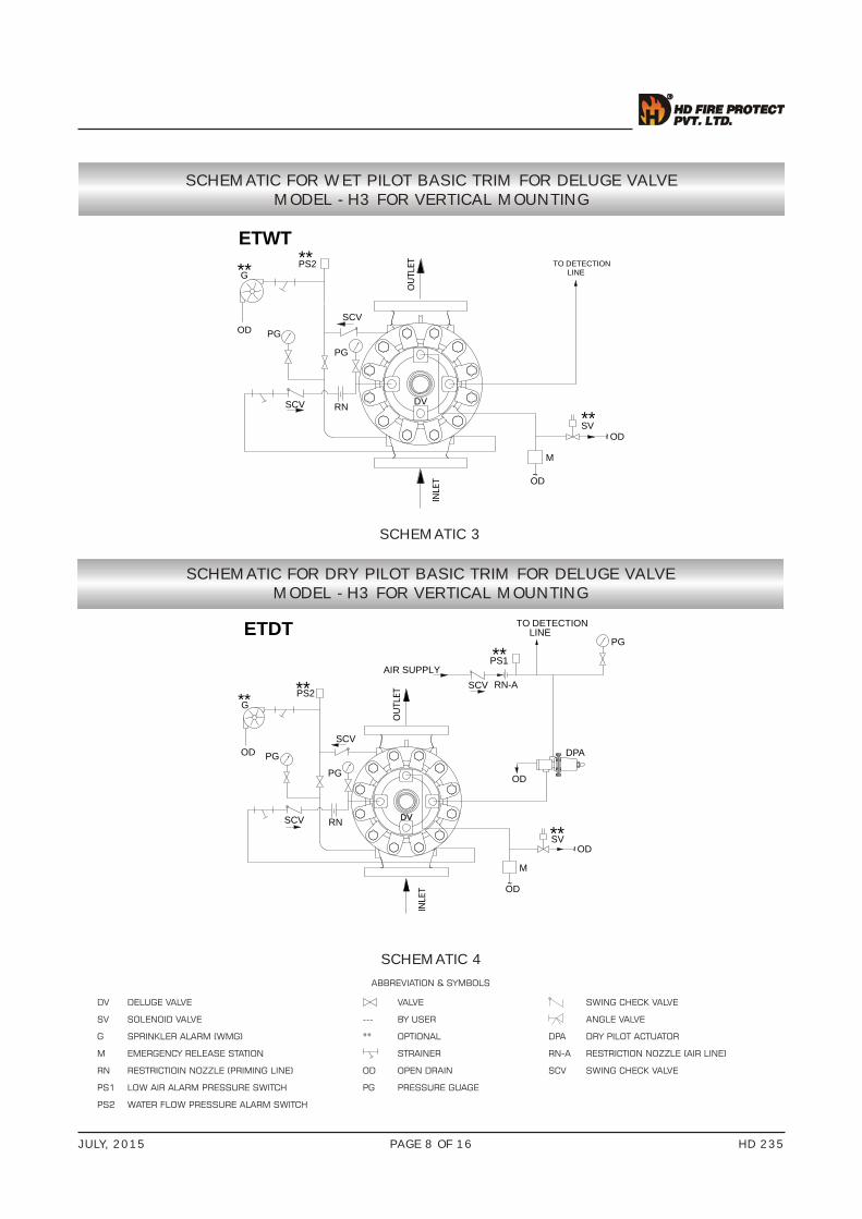
SCHEMATIC FOR WET PILOT BASIC TRIM FOR DELUGE VALVEMODEL - H3 FOR VERTICAL MOUNTING
SCHEMATIC FOR DRY PILOT BASIC TRIM FOR DELUGE VALVEMODEL - H3 FOR VERTICAL MOUNTING
SCHEMATIC 3
PG
~
M
SCV
PG
LINETO DETECTION
RN
OD
DV
SV**
~
G
OD
PS2**
SCV
ETWT
INLE
T
OU
TLET
OD
**
SCHEMATIC 4
PG
~
M
OD
PG
DPA
LINETO DETECTION
RN
OD
OD
DVDV
~
G
OD
PS2**
SCV
ETDT
INLE
T
OU
TLET
SCV
PG
SV**
SCV
**
PS1**AIR SUPPLY
RN-A
ABBREVIATION & SYMBOLS
DV DELUGE VALVE VALVE SWING CHECK VALVE
SV SOLENOID VALVE --- BY USER ANGLE VALVE
G SPRINKLER ALARM (WMG) ** OPTIONAL DPA DRY PILOT ACTUATOR
M EMERGENCY RELEASE STATION STRAINER RN-A RESTRICTION NOZZLE (AIR LINE)
RN RESTRICTIOIN NOZZLE (PRIMING LINE) OD OPEN DRAIN SCV SWING CHECK VALVE
PS1 LOW AIR ALARM PRESSURE SWITCH PG PRESSURE GUAGE
PS2 WATER FLOW PRESSURE ALARM SWITCH
JULY, 2015 HD 235PAGE 9 OF 16
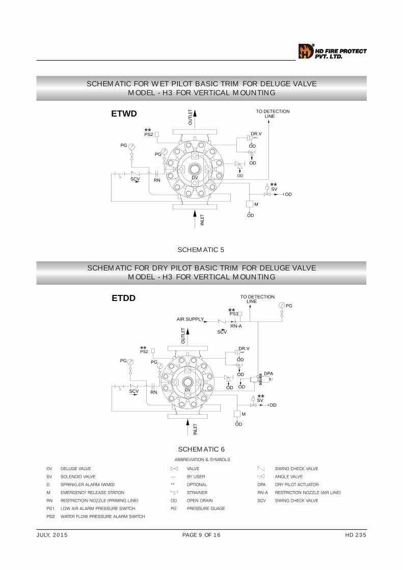
SCHEMATIC FOR WET PILOT BASIC TRIM FOR DELUGE VALVEMODEL - H3 FOR VERTICAL MOUNTING
SCHEMATIC FOR DRY PILOT BASIC TRIM FOR DELUGE VALVEMODEL - H3 FOR VERTICAL MOUNTING
SCHEMATIC 5
PG
~
M
OD
SCV
PG
LINETO DETECTION
RN
OD
DV
SV**
~
DR.V
OD
OD
~OD
ETWD
INLE
T
OU
TLET
PS2**
SCHEMATIC 6
PG
~
M
OD
PG
DPA
LINETO DETECTION
RN
OD
ODDV
~
DR.V
OD
OD
~OD
ETDD
INLE
T
OU
TLET
SCV
PG
SV**
SCV
PS1**AIR SUPPLY
RN-A
PS2**
ABBREVIATION & SYMBOLS
DV DELUGE VALVE VALVE SWING CHECK VALVE
SV SOLENOID VALVE --- BY USER ANGLE VALVE
G SPRINKLER ALARM (WMG) ** OPTIONAL DPA DRY PILOT ACTUATOR
M EMERGENCY RELEASE STATION STRAINER RN-A RESTRICTION NOZZLE (AIR LINE)
RN RESTRICTIOIN NOZZLE (PRIMING LINE) OD OPEN DRAIN SCV SWING CHECK VALVE
PS1 LOW AIR ALARM PRESSURE SWITCH PG PRESSURE GUAGE
PS2 WATER FLOW PRESSURE ALARM SWITCH
JULY, 2015 HD 235PAGE 10 OF 16
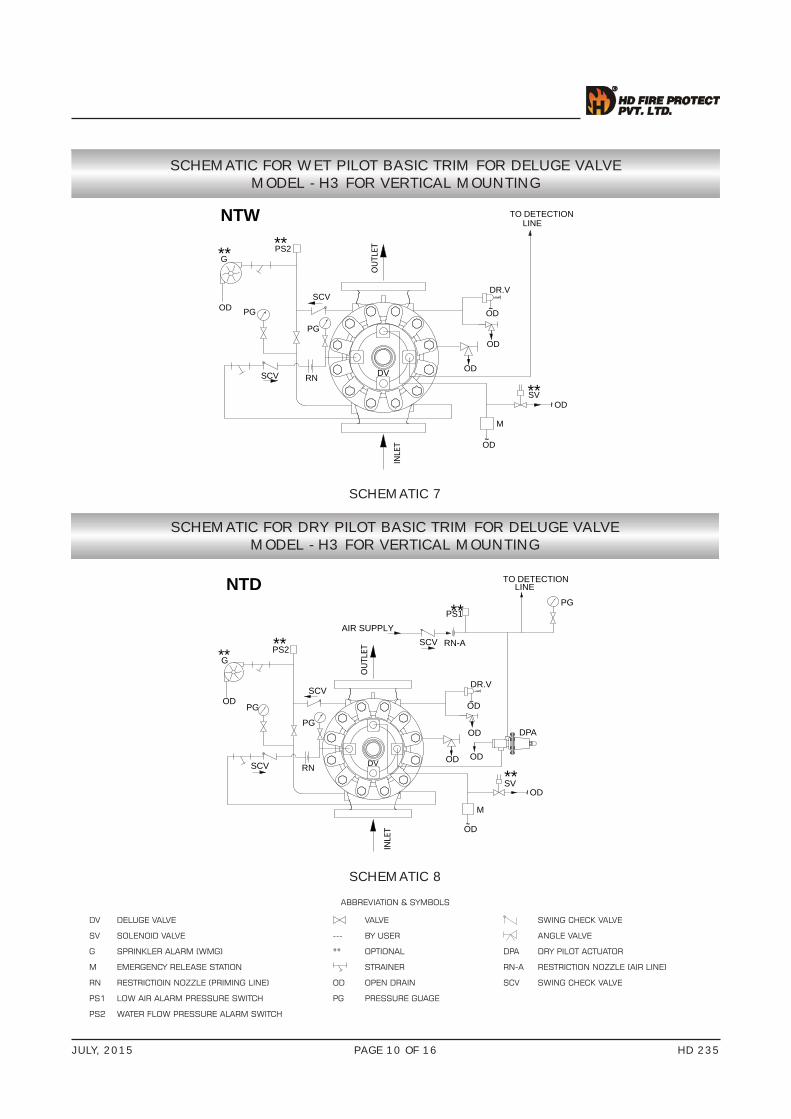
SCHEMATIC FOR WET PILOT BASIC TRIM FOR DELUGE VALVEMODEL - H3 FOR VERTICAL MOUNTING
SCHEMATIC FOR DRY PILOT BASIC TRIM FOR DELUGE VALVEMODEL - H3 FOR VERTICAL MOUNTING
SCHEMATIC 7
PG
~
M
OD
SCV
PG
RN
OD
DV
SV**
~
G
OD
PS2**
DR.V
OD
OD
~OD
LINETO DETECTION
SCV
NTW
INLE
T
OU
TLET**
SCHEMATIC 8
PG
~
M
OD
RN
OD
DV
~
G
OD
PS2**
PG
DR.V
DPA
LINETO DETECTION
OD
ODOD
~ODSCV
NTD
INLE
T
OU
TLET
SCV
PG
SV**
SCV**
PS1**AIR SUPPLY
RN-A
ABBREVIATION & SYMBOLS
DV DELUGE VALVE VALVE SWING CHECK VALVE
SV SOLENOID VALVE --- BY USER ANGLE VALVE
G SPRINKLER ALARM (WMG) ** OPTIONAL DPA DRY PILOT ACTUATOR
M EMERGENCY RELEASE STATION STRAINER RN-A RESTRICTION NOZZLE (AIR LINE)
RN RESTRICTIOIN NOZZLE (PRIMING LINE) OD OPEN DRAIN SCV SWING CHECK VALVE
PS1 LOW AIR ALARM PRESSURE SWITCH PG PRESSURE GUAGE
PS2 WATER FLOW PRESSURE ALARM SWITCH

JULY, 2015 HD 235PAGE 11 OF 16
SCHEMATIC FOR WET PILOT BASIC TRIM FOR DELUGE VALVEMODEL - H3 FOR HORIZONTAL MOUNTING
SCHEMATIC FOR DRY PILOT BASIC TRIM FOR DELUGE VALVEMODEL - H3 FOR HORIZONTAL MOUNTING
SCHEMATIC 9
INLET
PG
OUTLET
PG
ODSVM
OD
** RNSCV
~
~
LINEETW TO DETECTION
DV
PS2**
SCHEMATIC 10
INLET
PG
OUTLET
TO DETECTION
PG
LINE
PG
OD
DPA
SVM
OD
** RN
~
OD
~
SCV
ETD
PS1**AIR SUPPLY
RN-A
DV
PS2**
ABBREVIATION & SYMBOLS
DV DELUGE VALVE VALVE SWING CHECK VALVE
SV SOLENOID VALVE --- BY USER ANGLE VALVE
G SPRINKLER ALARM (WMG) ** OPTIONAL DPA DRY PILOT ACTUATOR
M EMERGENCY RELEASE STATION STRAINER RN-A RESTRICTION NOZZLE (AIR LINE)
RN RESTRICTIOIN NOZZLE (PRIMING LINE) OD OPEN DRAIN SCV SWING CHECK VALVE
PS1 WATER FLOW PRESSURE ALARM SWITCH PG PRESSURE GUAGE
PS2 LOW AIR ALARM PRESSURE SWITCH

JULY, 2015 HD 235PAGE 12 OF 16
SCHEMATIC FOR WET PILOT BASIC TRIM FOR DELUGE VALVEMODEL - H3 FOR HORIZONTAL MOUNTING
SCHEMATIC FOR DRY PILOT BASIC TRIM FOR DELUGE VALVEMODEL - H3 FOR HORIZONTAL MOUNTING
SCHEMATIC 11
INLET
PG
OUTLET
PG
ODSVM
OD
** RNSCV
~
~
TO DETECTIONLINE
PS2** G
~ODSCV
ETWT
**
DV
ABBREVIATION & SYMBOLS
DV DELUGE VALVE VALVE SWING CHECK VALVE
SV SOLENOID VALVE --- BY USER ANGLE VALVE
G SPRINKLER ALARM (WMG) ** OPTIONAL DPA DRY PILOT ACTUATOR
M EMERGENCY RELEASE STATION STRAINER RN-A RESTRICTION NOZZLE (AIR LINE)
RN RESTRICTIOIN NOZZLE (PRIMING LINE) OD OPEN DRAIN SCV SWING CHECK VALVE
PS1 LOW AIR ALARM PRESSURE SWITCH PG PRESSURE GUAGE
PS2 WATER FLOW PRESSURE ALARM SWITCH
SCHEMATIC 12
INLETPG
OUTLET
TO DETECTION
PG
LINE
PG
OD
DPA
SVM
OD
** RN
~
OD
~
G
~OD
PS2**
SCV
ETDT
PS1**AIR SUPPLY
**
RN-A
DV
JULY, 2015 HD 235PAGE 13 OF 16
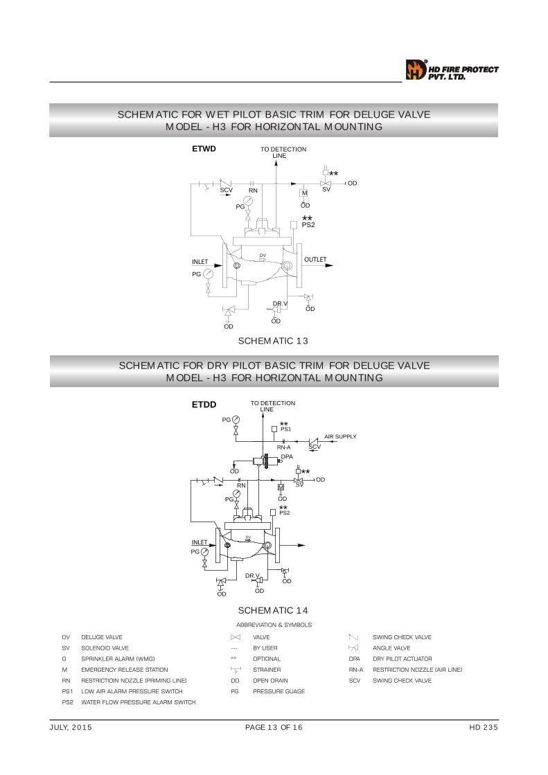
SCHEMATIC FOR WET PILOT BASIC TRIM FOR DELUGE VALVEMODEL - H3 FOR HORIZONTAL MOUNTING
SCHEMATIC FOR DRY PILOT BASIC TRIM FOR DELUGE VALVEMODEL - H3 FOR HORIZONTAL MOUNTING
SCHEMATIC 13
INLET
PG
OUTLET
PG
ODSVM
OD
** RNSCV
~
~
TO DETECTIONLINE
OD~
OD
DR.V ~OD
ETWD
DV
PS2**
SCHEMATIC 14
INLETPG
TO DETECTION
PG
LINE
PG
OD
DPA
SVM
OD
** RN
~
OD
~
OD~
OD
DR.V ~OD
SCV
ETDD
PS1**AIR SUPPLY
RN-A
DV
PS2**
ABBREVIATION & SYMBOLS
DV DELUGE VALVE VALVE SWING CHECK VALVE
SV SOLENOID VALVE --- BY USER ANGLE VALVE
G SPRINKLER ALARM (WMG) ** OPTIONAL DPA DRY PILOT ACTUATOR
M EMERGENCY RELEASE STATION STRAINER RN-A RESTRICTION NOZZLE (AIR LINE)
RN RESTRICTIOIN NOZZLE (PRIMING LINE) OD OPEN DRAIN SCV SWING CHECK VALVE
PS1 LOW AIR ALARM PRESSURE SWITCH PG PRESSURE GUAGE
PS2 WATER FLOW PRESSURE ALARM SWITCH

JULY, 2015 HD 235PAGE 14 OF 16
SCHEMATIC FOR WET PILOT BASIC TRIM FOR DELUGE VALVEMODEL - H3 FOR HORIZONTAL MOUNTING
SCHEMATIC FOR DRY PILOT BASIC TRIM FOR DELUGE VALVEMODEL - H3 FOR HORIZONTAL MOUNTING
SCHEMATIC 15
OD~
OD
DR.V ~OD
INLET OUTLET
NTW
PG
ODSVM
OD
** RNSCV
~
~
TO DETECTIONLINE
PS2** G
~OD
SCV
**
DV
SCHEMATIC 16
OD~
DR.V
PG
~OD
TO DETECTION
PG
LINEPG
OD
DPA
M
OD
RN
PS2**
SV**
~
OD
~
INLET OUTLET
G
~OD
SCV
NTDPS1**
AIR SUPPLY
**
RN-A
OD~
DV
ABBREVIATION & SYMBOLS
DV DELUGE VALVE VALVE SWING CHECK VALVE
SV SOLENOID VALVE --- BY USER ANGLE VALVE
G SPRINKLER ALARM (WMG) ** OPTIONAL DPA DRY PILOT ACTUATOR
M EMERGENCY RELEASE STATION STRAINER RN-A RESTRICTION NOZZLE (AIR LINE)
RN RESTRICTIOIN NOZZLE (PRIMING LINE) OD OPEN DRAIN SCV SWING CHECK VALVE
PS1 LOW AIR ALARM PRESSURE SWITCH PG PRESSURE GUAGE
PS2 WATER FLOW PRESSURE ALARM SWITCH

JULY, 2015 HD 235PAGE 15 OF 16
SPRINKLER HEIGHT LIMITATION
DV 150NBDV 200NB
DV 100NB DV 80NB
DV - 50NB
SYSTEM SUPPLY PRESSURE - PSI ------EQUIVALENT LENGTH BASED ON 1/2” SCHEDULE 40 PIPE WITH C=120
KG/SQCM
METER
S
MAX
IMU
M P
ILO
T LI
NE
HIG
HT
- FEE
T --
----
SYSTEM SUPPLY PRESSURE - PSI ------EQUIVALENT LENGTH BASED ON 1/2” SCHEDULE 40 PIPE WITH C=120
KG/SQCM
METER
S
MAX
IMU
M P
ILO
T LI
NE
HIG
HT
- FEE
T --
----
SYSTEM SUPPLY PRESSURE - PSI ------EQUIVALENT LENGTH BASED ON 1/2” SCHEDULE 40 PIPE WITH C=120
KG/SQCM
METER
S
MAX
IMU
M P
ILO
T LI
NE
HIG
HT
- FEE
T --
----
SYSTEM SUPPLY PRESSURE - PSI ------EQUIVALENT LENGTH BASED ON 1/2” SCHEDULE 40 PIPE WITH C=120
KG/SQCM
METER
SM
AXIM
UM
PIL
OT
LIN
E H
IGH
T - F
EET
-----
-
SYSTEM SUPPLY PRESSURE - PSI ------EQUIVALENT LENGTH BASED ON 1/2” SCHEDULE 40 PIPE WITH C=120
KG/SQCM
METER
S
MAX
IMU
M P
ILO
T LI
NE
HIG
HT
- FEE
T --
----
60
20
20
40
120
80
100
140
5
10
15
20
25
30
35
4040
2 4 6 8 10 12
160
180
200
14 16 18
45
50
55
60
50 100 150 200 250
0
220.65
25 FEET
250 FEET
500 FEET
60
20
20
40
120
80
100
140
5
10
15
20
25
30
35
4040
2 4 6 8 10 12
160
180
200
14 16 18
45
50
55
60
50 100 150 200 250
0
220.65
25 FEET
250 FEET
500 FEET
60
20
20
40
120
80
100
140
5
10
15
20
25
30
35
4040
2 4 6 8 10 12
160
180
200
14 16 18
45
50
55
60
50 100 150 200 250
0
220.
240
65
70
25 F
EET
250 FEET
500 FE
ET
60
20
20
40
120
80
100
140
5
10
15
20
25
30
35
4040
2 4 6 8 10 12
160
180
200
14 16 18
45
50
55
60
50 100 150 200 250
0
220.
240
65
70
25 F
EET
250 F
EET
500 FEET
60
20
20
40
120
80
100
140
5
10
15
20
25
30
35
4040
2 4 6 8 10 12
160
180
200
14 16 18
45
50
55
60
50 100 150 200 250
0
220.65
25 F
EET
250
FEET
500 FEET
JULY, 2015 HD 235PAGE 16 OF 16
LIMITED WARRANTY
HD FIRE PROTECT PVT. LTD. hereby referred to as HD FIRE warrants to the original purchaser of the fire protection products manufactured by HD FIRE and to any other person to whom such equipment is transferred, that such products will be free from defect in material and workmanship under normal use and care, for two (2) years from the date of shipment by HD FIRE. Products or Components supplied or used by HD FIRE, but manufactured by others, are warranted only to the extent of the manufacturer’s warranty. No warranty is given for product or components which have been subject to misuse, improper installation, corrosion, unauthorized repair, alteration or un-maintained. HD FIRE shall not be responsible for system design errors or improper installation or inaccurate or incomplete information supplied by buyer or buyer’s representatives.HD FIRE will repair or replace defective material free of charge, which is returned to our factory, transportation charge prepaid, provided after our inspection the material is found to have been defective at the time of initial shipment from our works. HD FIRE shall not be liable for any incidental or consequential loss, damage or expense arising directly or indirectly from the use of the product including damages for injury to person, damages to property and penalties resulting from any products and components manufactured by HD FIRE. HD FIRE shall not be liable for any damages or labour charges or expense in making repair or adjustment to the product. HD FIRE shall not be liable for any damages or charges sustained in the adaptation or use of its engineering data & services. In no event shall HD Fire’s product liability exceed an amount equal to the sale price.The foregoing warranty is exclusive and in lieu of all other warranties and representation whether expressed, implied, oral or written, including but not limited to, any implied warranties or merchantability or fitness for a particular purpose. All such other warranties and representations are hereby cancelled.
NOTICE :
The equipment presented in this bulletin is to be installed in accordance with the latest publication standards of NFPA or other similar organisations and also with the provision of government codes or ordinances wherever applicable.The information provided by us are to the best of our knowledge and belief, and are general guidelines only. Site handling and installation control is beyond our reach. Hence we give no guarantee for result and take no liability for damages, loss or penalties whatsoever, resulting from our suggestion, information, recommendation or damages due to our product.Product development is a continuous programme of HD FIRE PROTECT PVT. LTD. and hence the right to modify any specification without prior notice is reserved with the company.
C-3/6, THE NANDANVAN IND. ESTATE, L.B.S. MARG, THANE 400 604., INDIA.• PHONES : + (91) 22 2583 5434 • 2582 6958 • 2582 6793 • FAX : +(91) 22 2581 2524 • 6796 9049• EMAIL : [email protected] WEBSITE : www.hdfire.com
HD FIRE PROTECT PVT. LTD.Protecting What Matters Most to You
DELUGE VALVE MODEL H3
0.1
0.2
0.30.40.50.60.81.0
2
34568
10
20
3040
100 1000800600400300200 2000 10000 20000700050003000
50
NB
(
2
INCH
)
80
NB
(
3INCH
)
100
NB
(
4
INCH
)15
0
NB
(
6
INCH
)
200
NB
(
8
INCH
)
** *
* *
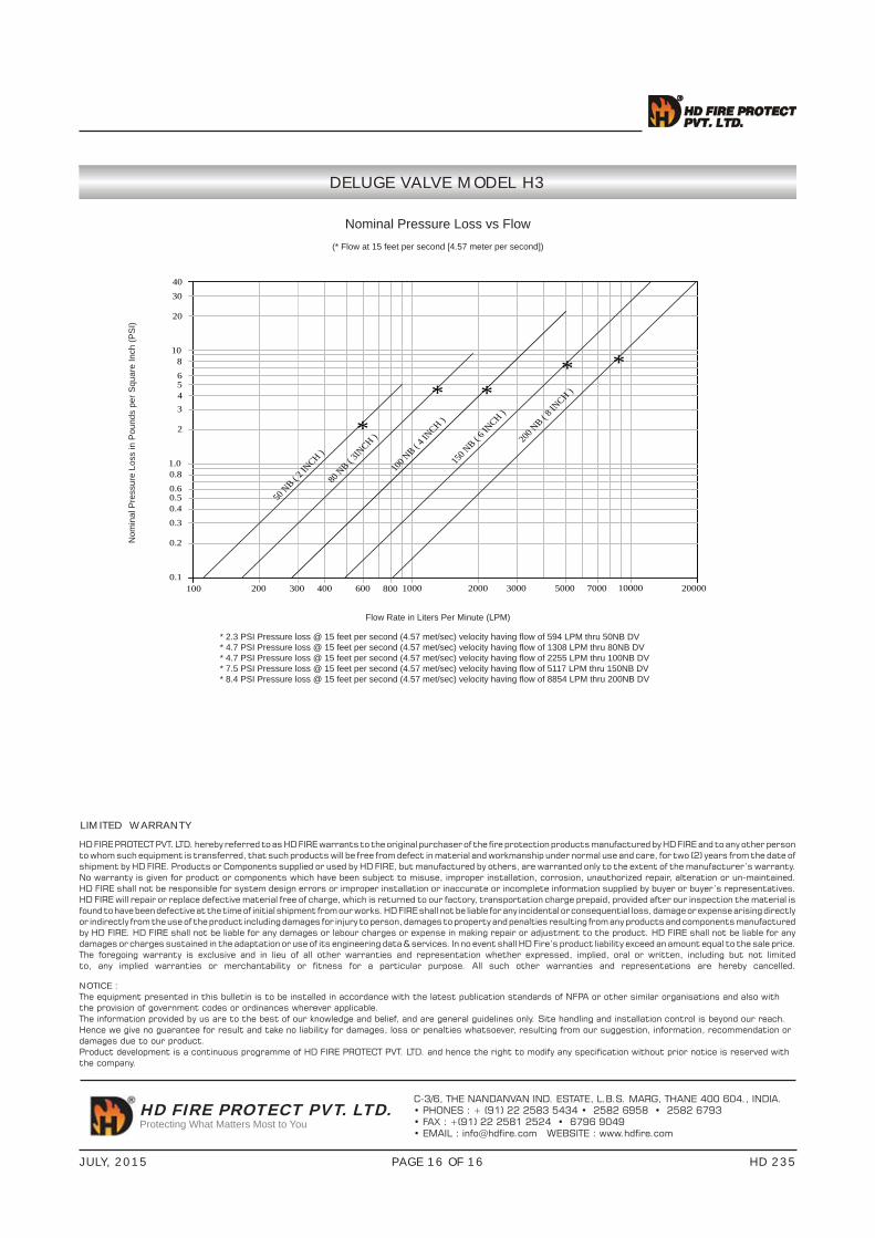
* 2.3 PSI Pressure loss @ 15 feet per second (4.57 met/sec) velocity having fl ow of 594 LPM thru 50NB DV* 4.7 PSI Pressure loss @ 15 feet per second (4.57 met/sec) velocity having fl ow of 1308 LPM thru 80NB DV* 4.7 PSI Pressure loss @ 15 feet per second (4.57 met/sec) velocity having fl ow of 2255 LPM thru 100NB DV* 7.5 PSI Pressure loss @ 15 feet per second (4.57 met/sec) velocity having fl ow of 5117 LPM thru 150NB DV* 8.4 PSI Pressure loss @ 15 feet per second (4.57 met/sec) velocity having fl ow of 8854 LPM thru 200NB DV
Nominal Pressure Loss vs Flow(* Flow at 15 feet per second [4.57 meter per second])
Nom
inal
Pre
ssur
e Lo
ss in
Pou
nds
per S
quar
e In
ch (P
SI)
Flow Rate in Liters Per Minute (LPM)