demag drives - karincranes.com · combination of gearboxes and motors using demag coupling shaft...
TRANSCRIPT
Demag drives
Keeping things on the move

2
Demag drives make things movefrom single gearboxes to complete travel units
Matching our experience to your application Demag Cranes & Components provides material flow, logistics and drive solutions of the highest standard and at peak performance rates – for every field of industry and for companies of all sizes – from small workshops to major industrial corporations.
In the interest of our customers, we have applied nearly 200 years of experience in industrial crane manufacture to other applications and made drive technology an integral part of our holistic product philosophy.
Wherever you have things to move, you‘ll find usAt Demag, we supply drive modules from individual sub-assemblies to complete systems and also integrate them in our own system products.
Demag drive technology keeps things moving in almost every field of application – reliable, safe technology that has proven its worth a thousand times over:
■■ cranes and handling equipment■■ transport logistics■■ mechanical engineering■■ moving architectural elements.
For cranes and handling equipment For transfer logistics
3928
1-15
405
29-2

3
One source – countless solutionsAs a leading supplier of drive technology, Demag Cranes & Components provides a full product range:
■■ motors, gearboxes and geared motors■■ power supply systems■■ frequency inverters■■ wheel systems■■ complete travel units.
All the individual components are matched to each other because it is only by ensuring perfect interaction be-tween them, and by integrating the intelligent control system, that an efficient overall system can be achieved.
Design is a simple matter – with the right systemOur modular approach enables you to create economical, individual solutions quickly using standardised modules.
This not only saves valuable time at the project planning stage but also ensures the final design is a safe product. You can benefit from our extensive experience and know-how in machines and equipment.
For engineering For movable architectural elements
389
44
-5-2
3818
0

4
Demag modular drive technology system –a perfect blend of proven components
DCL power supply system■■ Up to 200 A at 60% CDF■■ Up to seven conductors
Project planning tools■■ Design software■■ Online configuration■■ Online ordering system
Frequency inverters■■ DeDrive Compact STO – for motor outputs of up to 110 kW
■■ DeDrive Pro – for motor outputs of up to 560 kW
Offset geared motors
Microspeed drives
Angular geared motors
Conical-rotor brake motors
388
81-1
3739
9-2
3737
1-1
3935
0-7
5
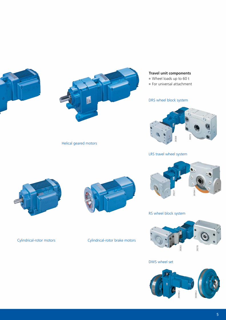
Travel unit components■■ Wheel loads up to 60 t■■ For universal attachment
Helical geared motors
Cylindrical-rotor motors Cylindrical-rotor brake motors
RS wheel block system
DRS wheel block system
LRS travel wheel system
DWS wheel set
3938
439
227
3938
339
398
-2
3937
2
3919
4-1
3937
839
399
-2

6
Geared motors – combined strengths
D-type helical gearbox
W-type angular gearbox
A-type offset gearbox
Intermediate stage (optional)
ZN cylindrical-rotor motor
ZB cylindrical-rotor brake motor (brake shown in grey)
If you are looking for perfectly matched motors and gearboxes, our modular range of units has been designed to meet your requirements:A-type offset gearboxes AW-type angular gearboxes WD-type helical gearboxes D
You can combine these gearboxes with a number of motor units:Z-type cylindrical-rotor motors Z
■■ With or without a brake ZB/ZN■■ For general applications ZBA/ZNA■■ For travel applications ZBF■■ For continuous duty (energy-efficient motors) ZBE/ZNE
Conical-rotor brake motors KB■■ For general applications KBA■■ For travel applications KBF
Choose the right brake for the jobTo allow you to match the braking torque to the specific application, we have a number of versions to meet your requirements:
■■ ZB cylindrical-rotor brake motors offering a choice of two different brake sizes
■■ additional fine-tuning by combining different numbers and types of brake springs
■■ KB conical-rotor brake motors for cases involving extremely high braking energy and start-stop frequency.
This is how you benefit from FG microspeed unitsOur microspeed units make it possible to achieve large mechanical speed ratios of up to 500 : 1 between main and positioning speeds.
Direct drive inputThe gearbox and Z-type cylindrical-rotor motor can be connected through end shields. A-type offset gearboxes are available in two- and three-speed versions. The transmission ratio range of D-type helical gearboxes and W-type angular gearboxes can be increased by means of an intermediate stage.

7
D-type helical gearboxes
W-type angular gearboxes
A-type offset gearbox
Coupling
ZN cylindrical-rotor motor
ZB cylindrical-rotor brake motor (brake shown in grey)
KB conical-rotor brake motor
Z AB MA E
Z cylindrical-rotor motorK conical-rotor brake motor
A offset gearboxW angular gearboxesD helical gearboxes
B with integrated brake (ZB, KB)N without a brake (ZN)
U universal mountingG foot mountingF flange-mountingM torque bracket arrangement – splined connectionD torque bracket arrangement – bolted flange connection
A general applications, intermittent dutyE continuous duty, efficiency class IE2 F travel applications
V solid shaft with keyE splined solid shaftH hollow shaft with keyK splined hollow shaft B hollow shaft with shrink disc
Simply adapt our technology to your needsOur modular system is designed to be tailored to the most varied needs. Even the standard versions of these products provide numerous combination possibilities. A wide choice of options and accessories rounds off the range. Mounting variants simplify the task of optimising the design solution. Rotary encoders and temperature detectors enable additional functions to be integrated.
You can count on our supportIn addition to offering our modular system, we support our customers with these tools:
■■ an extensive catalogue of detailed information■■ software for calculating drives■■ an online tool for configuring your drive solution■■ highly dedicated staff to advise you.
Coupling connectionCombination of gearboxes and motors using Demag coupling shaft end (Z-type cylindrical-rotor motors or KB-type conical-rotor brake motors) via an intermediate flange and roller spider coupling. Since there is no oil present in the coupling housing, gearboxes can be fitted independent of the motor and the motors can be easily disassembled.

8
A-type offset gearboxes – the space-saving alternative
Gearbox size
Output torque [Nm]
Transmission ratio (i)
2-stage 3-stage
A10 130 8.32 – 52.5 –
A20 205 6.21 – 28.0 31.7 – 123
A30 370 7.78 – 71.9 82.4 – 156
A40 660 8.78 – 61.6 73.8 – 256
A50 1,150 8.69 – 71.6 78.0 – 218
A60 2,100 8.91 – 67.9 77.2 – 297
A70 3,700 9.23 – 68.1 78.9 – 267
A80 6,600 9.89 – 68.9 80.3 – 281
A90 11,500 10.2 – 69.7 76.3 – 274
AM 10 – 40 torque bracket type
AD 40 – 80 AU 20 – 90 universal type
AF 20 – 90 flange mounting AG 30 – 90 foot-mounting
The wide range of housing types available provides plenty of choice for designers
A10 – A40: Aluminium housingA50 – A90: Grey cast housing
For torques from 130 to 11,500 Nm For maximum flexibility: 5 housing designs
If you are looking for space-saving drive units, our A-type offset gearboxes have been designed specifically for that purpose:
■■ wide range of gear ratios■■ economical high-efficiency solutions ■■ practically orientated design.
Thanks to these characteristics, they have become the preferred choice for many travel applications.
Variable drive outputThe possible drive shafts available include:
■■ solid shaft■■ with a key■■ with involute splines (one or both sides)
■■ hollow shaft■■ with a key■■ with involute splines■■ with shrink disc.
Offset geared motor with torque bracket arrangement for
gentle transmission of drive torque without any radial forces via a solid shaft
with involute splines
3939
2-1

9
38224
3675
4
3939
2
Torque bracket for transmission of drive torque without any radial forces
At a glance
■■ Nine gearbox sizes■■ Torques from 130 to 11,500 Nm■■ Direct input or coupling connection■■ Five housing types■■ Five shaft types■■ Many more options and accessories (see page 18)
The benefits of design & engineering Demag offset gearboxes feature large shaft centre distances, which benefits:
■■ ground-level travel units with large ground clearance ■■ central drive arrangements with shafts on both sides.
Proven torque transmission method The AM torque bracket arrangement has been designed as a hollow-shaft gearbox with a torque ring integrated in the housing cover (AM 10–40). This torque ring trans-mits the drive torque without any radial forces to Demag DRS wheel blocks via a specially designed torque bracket. This sophisticated combination for travel drives with reversing operation is a preferred choice and will benefit your business.
Offset geared motors: seen here as a central drive arrangement with large ground clearance fitted to a tool-changing carriage. These systems are particularly efficient in conjunction with Demag wheel blocks and corresponding torque brackets.
3822
4

10
The compact solution – W-type angular gearboxes
Gearbox size
Output torque [Nm]
Transmission ratio (i)
2-stage 3-stage 4-stage
W10 120 5.34 – 100 – –
W20 200 5.45 – 90.1 97.1 – 369 –
W30 330 3.73 – 90.1 107 – 369 –
W40 500 3.87 – 90.8 99.6 – 371 –
W50 800 4.94 – 94.3 99.9 – 386 –
W60 1,350 – 12.6 – 95.1 113 – 388
W70 2,500 – 13.7 – 102 113 – 399
W80 4,000 – 15.3 – 113 126 – 441
W90 7,000 – 15.9 – 111 126 – 434
W100 12,000 – 16.5 – 113 121 – 485
The right fit, always, thanks to various housing types
W10 – W40: Aluminium housingW50 – W100: Grey cast housing
For torques from 120 to 12,000 Nm For maximum flexibility: four housing types
Universal type WU
1 WG foot-mounting – bottom-mounted
2 WG foot-mounting – end-mounted
WF flange-mounting
If you need angular gearboxes to enable very compact designs, our W-type gearboxes are the answer. They enable travel motions to be provided, for example, even when the distance from the rail is very restricted:
■■ large torques from 120 to 12,000 Nm■■ broad range of ratios.
Smooth-running hypoid gearboxes Sizes W10 to W50 are designed as hypoid gearboxes:
■■ very smooth running■■ large transmission ratio range in hypoid stage.
Highly efficient bevel gearboxesW60 to W100 gearboxes are all bevel gearboxes:
■■ excellent efficiency■■ three-stage gearing providing high transmission ratios even in the basic versions.
Universal design of W-type angular geared motor enables flexible fitting
3938
9-1
11
At a glance
■■ Ten gearbox sizes■■ Torques from 120 to 12,000 Nm■■ W10 – W50 hypoid gearboxes for specially smooth running characteristics
■■ W60 – W100 bevel-wheel gearboxes, high efficiency rating
■■ Direct input or coupling connection■■ Four housing types■■ Five shaft types■■ Many more options and accessories (see page 18)
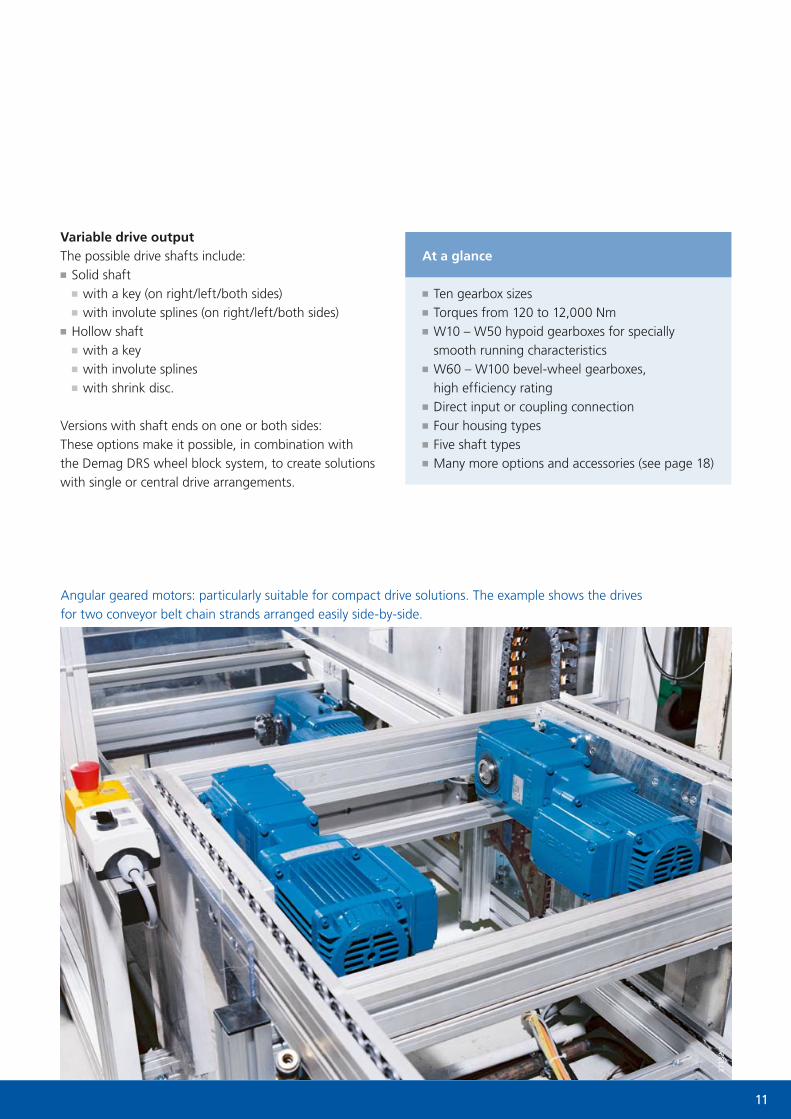
Variable drive outputThe possible drive shafts include:
■■ Solid shaft■■ with a key (on right/left/both sides)■■ with involute splines (on right/left/both sides)
■■ Hollow shaft■■ with a key■■ with involute splines■■ with shrink disc.
Versions with shaft ends on one or both sides: These options make it possible, in combination with the Demag DRS wheel block system, to create solutions with single or central drive arrangements.
Angular geared motors: particularly suitable for compact drive solutions. The example shows the drives for two conveyor belt chain strands arranged easily side-by-side.
3713
2-1

12
Gearbox size
Output torque [Nm]
Transmission ratio (i)
2-stage 3-stage
D11 90 2.88 – 66.5 –
D21 130 2.88 – 66.5 –
D31 200 3.23 – 61.6 66.4 – 253
D41 330 3.23 – 58.6 49.5 – 240
D50 550 2.78 – 61.4 71.9 – 251
D60 1,000 6.44 – 48.4 57.5 – 197
D70 1,800 6.89 – 51.3 56.7 – 201
D80 3,200 7.03 – 49.5 55.5 – 192
D90 5,800 7.49 – 51.2 55.1 – 220
D-type helical gearboxes – the robust ones
Designed for the purpose – different housing types to match your needs
D11 – D41: Aluminium housingD50 – D90: Grey cast housing
For torques from 90 to 5,800 Nm For maximum flexibility: three housing types
DF flange mounting
DU 11 – 41 foot or flange mounting
DG foot mounting
If you are looking for tough drive solutions, Demag D-type helical gearboxes are known for their resilience:
■■ torques from 90 to 5,800 Nm■■ excellent efficiency rating thanks to helical spur gears■■ high radial forces can be applied through the output shaft.
Output – made to measure The output shaft is a solid shaft with a key, due to the coaxial design of the helical gearbox.
Helical geared motors with foot mounting
for robust drive solutions
3938
1
13
At a glance
■■ Nine gearbox sizes■■ Torques from 90 to 5,800 Nm■■ Direct input or coupling connection■■ Three housing types■■ Output via solid shaft with a key■■ Many more options and accessories (see page 18)
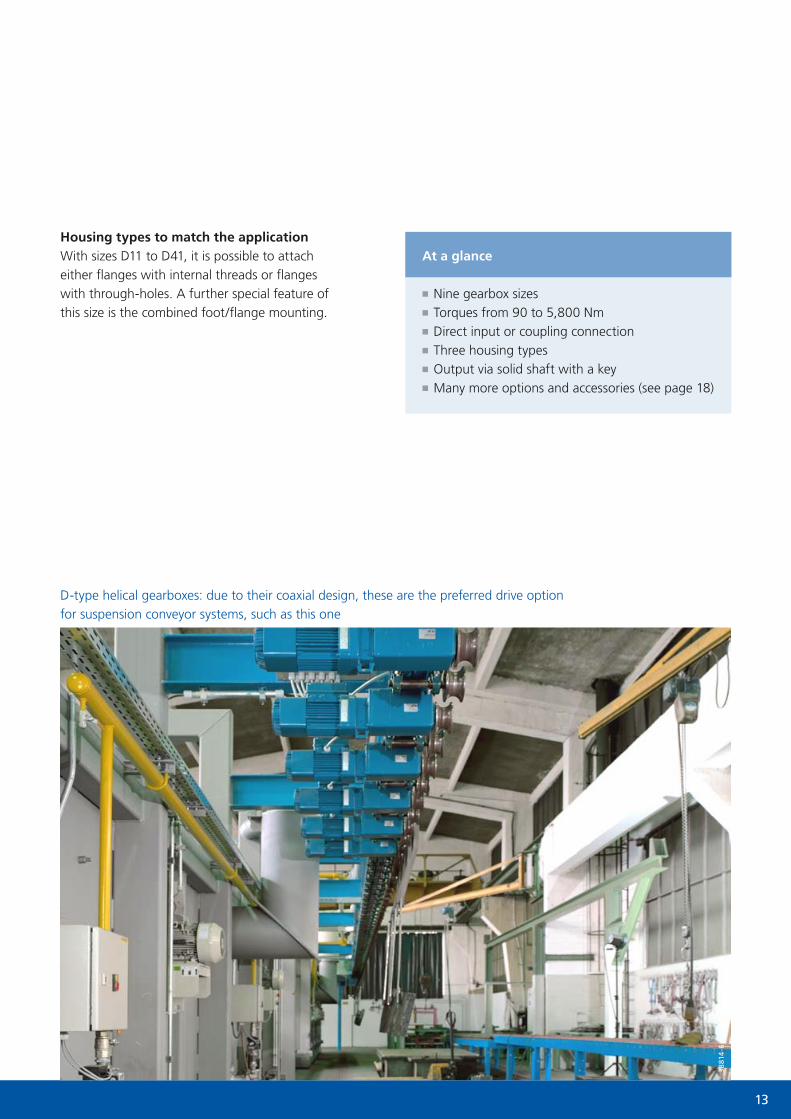
Housing types to match the applicationWith sizes D11 to D41, it is possible to attach either flanges with internal threads or flanges with through-holes. A further special feature of this size is the combined foot/flange mounting.
D-type helical gearboxes: due to their coaxial design, these are the preferred drive option for suspension conveyor systems, such as this one
3881
4-6

14
Z-type cylindrical-rotor motors for universal use
DesignationZBA = braked
ZNA = unbraked
Output [kW]60% CDF
60°C temp.
ZBA/ZNA 63 B4 0.18
ZBA/ZNA 71 A4 0.25
ZBA/ZNA 71 B4 0.37
ZBA/ZNA 80 A4 0.55
ZBA/ZNA 80 B4 0.75
ZBA/ZNA 90 A4 1.1
ZBA/ZNA 90 B4 1.5
ZBA/ZNA 100 AL4 2.2
ZBA/ZNA 100 B4 3
ZBA/ZNA 112 A4 4
ZBA/ZNA 132 AL4 5.5
ZBA/ZNA 132 B4 7.5
ZBA/ZNA 132 C4 9.5
ZBA/ZNA 160 AL4 11
ZBA/ZNA 160 B4 15
ZBA/ZNA 180 A4 18.5
ZBA/ZNA 180 B4 22
ZBA/ZNA 200 A4 30
ZBA/ZNA225 AL4 37
ZBA/ZNA 225 B4 45
For outputs of up to 45 kW: four-pole ZBA/ZNA motors Efficiency ratings in line with IE2: 4-pole ZBE/ZNE motors
DesignationZBE = braked
ZNE = unbraked
Output [kW]100% CDF40°C temp.
Efficiency rating [%]
η50 η75 η100
ZBE/ZNE 80 B4 0.75 79.3 82.2 79.6
ZBE/ZNE 90 A4 1.1 79.8 82.3 81.4
ZBE/ZNE 90 B4 1.5 82.1 83.4 82.8
ZBE/ZNE 100 A4 2.2 83.8 84.9 84.3
ZBE/ZNE 100 B4 3 83.6 86.4 85.5
ZBE/ZNE 112 A4 4 86 87.4 86.6
ZBE/ZNE 132 A4 5.5 87.2 88.3 87.7
ZBE/ZNE 132 B4 7.5 87.5 90.3 88.7
ZBE/ZNE 160 A4 11 89 90.8 89.8
ZBE/ZNE 160 B4 15 89.2 91.8 90.6
ZBE/ZNE 180 A4 18.5 89.3 92.4 91.2
ZBE/ZNE 180 B4 22 89.2 92.3 91.6
ZBE/ZNE 200 A4 30 88.4 92.8 92.3
ZBE/ZNE 225 A4 37 90.8 93.2 92.7
ZBE/ZNE 225 B4 45 92.2 93.5 93.1
If you are looking for motors that are able to meet the most varied drive technology needs reliably and efficiently, our Z-type cylindrical-rotor motors offer many advantages:
■■ perfectly matched to our range of gearboxes■■ simple project engineering■■ best possible drive efficiency.
Tell us the task in hand – we have the solution Z-type cylindrical-rotor motors are available with outputs of up to 45 kW:
■■ 2, 4, 6 and 8 pole (motor efficiency in line with IEC ratings)■■ pole-changing with two speeds■■ braked (ZB) and unbraked (ZN).
The right cylindrical-rotor motor for your application■■ ZBA/ZNA motors for travel applications in conjunction with an inverter
■■ ZBF motors for line-fed travel applications ■■ ZBE/ZNE motors for continuous duty in efficiency class IE2.
3938
5
Cylindrical-rotor motors are well suited to a broad range of applications
15
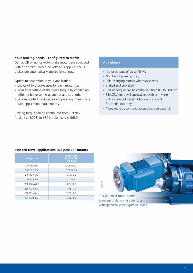
DesignationOutput [kW]40/40% CDF 40°C temp.
ZBF 63 A 8/2 0.06 / 0.25
ZBF 71 A 8/2 0.09 / 0.34
ZBF 80 A 8/2 0.13 / 0.5
ZBF 90 B 8/2 0.2 / 0.8
ZBF 100 A 8/2 0.29 / 1.2
ZBF 112 A 8/2 0.46 / 1.9
ZBF 132 A 8/2 0.72 / 2.9
ZBF 132 B 8/2 0.88/ 3.5ZB cylindrical-rotor motor: excellent braking characteristics with specifically configurable brake
Line-fed travel applications: 8/2-pole ZBF motors
3938
0-1
At a glance
■■ Motor outputs of up to 45 kW■■ Number of poles: 2, 4, 6, 8■■ Pole-changing motors with two speeds■■ Braked and unbraked■■ Braking torques can be configured from 0.9 to 680 Nm■■ ZBA/ZNA for travel applications with an inverter, ZBF for line-fed travel motions and ZBE/ZNE for continuous duty
■■ Many more options and accessories (see page 18)
Your braking needs – configured to matchDemag ZB cylindrical-rotor brake motors are equipped with disc brakes. When no voltage is applied, the DC brakes are automatically applied by springs.
Optimum adaptation to your application:■■ choice of two brake sizes for each motor size■■ even finer setting of the brake torque by combining differing brake spring quantities and strengths
■■ various control modules allow operating times in line with application requirements.
Braking torque can be configured from 0.9 Nm (brake size B003) to 680 Nm (brake size B680).
16
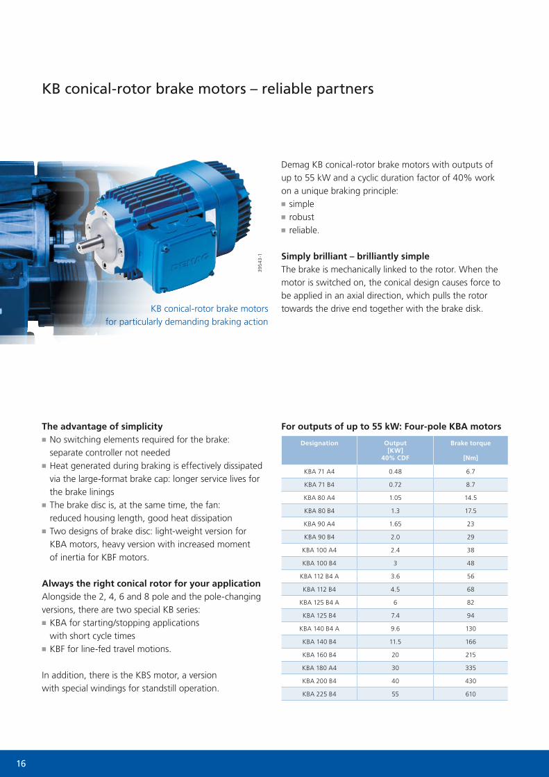
The advantage of simplicity■■ No switching elements required for the brake: separate controller not needed
■■ Heat generated during braking is effectively dissipated via the large-format brake cap: longer service lives for the brake linings
■■ The brake disc is, at the same time, the fan: reduced housing length, good heat dissipation
■■ Two designs of brake disc: light-weight version for KBA motors, heavy version with increased moment of inertia for KBF motors.
Always the right conical rotor for your applicationAlongside the 2, 4, 6 and 8 pole and the pole-changing versions, there are two special KB series:
■■ KBA for starting/stopping applications with short cycle times
■■ KBF for line-fed travel motions.
In addition, there is the KBS motor, a version with special windings for standstill operation.
Demag KB conical-rotor brake motors with outputs of up to 55 kW and a cyclic duration factor of 40% work on a unique braking principle:
■■ simple■■ robust■■ reliable.
Simply brilliant – brilliantly simpleThe brake is mechanically linked to the rotor. When the motor is switched on, the conical design causes force to be applied in an axial direction, which pulls the rotor towards the drive end together with the brake disk.
KB conical-rotor brake motors – reliable partners
Designation Output[KW]
40% CDF
Brake torque
[Nm]
KBA 71 A4 0.48 6.7
KBA 71 B4 0.72 8.7
KBA 80 A4 1.05 14.5
KBA 80 B4 1.3 17.5
KBA 90 A4 1.65 23
KBA 90 B4 2.0 29
KBA 100 A4 2.4 38
KBA 100 B4 3 48
KBA 112 B4 A 3.6 56
KBA 112 B4 4.5 68
KBA 125 B4 A 6 82
KBA 125 B4 7.4 94
KBA 140 B4 A 9.6 130
KBA 140 B4 11.5 166
KBA 160 B4 20 215
KBA 180 A4 30 335
KBA 200 B4 40 430
KBA 225 B4 55 610
For outputs of up to 55 kW: Four-pole KBA motors
395
43-1
KB conical-rotor brake motors for particularly demanding braking action

17
Synchronised actionThe brake is released at exactly the moment the motor begins to rotate. When the motor is switched off, the brake is immediately applied.
Superior brakingOur KB motors are the superior choice wherever the highest demands are made on the brake:
■■ designed for heavy-duty brake operation■■ extremely high start-stop frequencies permitted■■ resistant to temporary overload.
Designation Output[KW]
40/40% CDF
Brake torque
[Nm]
KBF 71 A 8/2 0.04 / 0.2 1.4
KBF 71 B 8/2 0.06 / 0.3 1.6
KBF 80 A 8/2 0.13 / 0.5 3.2
KBF 90 A 8/2 0.2 / 0.8 5.2
KBF 100 A 8/2 0.26 / 1.2 7.0
KBF 112 A 8/2 0.42 / 1.9 11.8
KBF 125 A 8/2 0.65 / 2.9 17
KBF 140 A 8/2 1.1 / 4.5 24.3
394
46
Line-fed travel applications: 8/2-pole KBF motors
Brake spring
Unique design provides mechanical link between the rotor and the brake
Rotor Stator Brake disc Brake lining Brake cap
At a glance
■■ Motor output up to 55 kW at 40% CDF■■ Number of poles: 2, 4, 6, 8■■ Pole-changing motors with two speeds■■ KBA drives for starting and stopping, KBF for line-fed travel operations
■■ Many more options and accessories (see page 18)

18
If you have a demanding application that needs more, even the standard versions of Demag drive technology products provide the opportunity to tailor functionality to suit specific requirements.
Comprehensive set of features and accessories
Gearboxes
Options A offset gearboxes
W angular gearboxes
D helical gearboxes
Torque brackets ■
Foot rails/foot plates ■ ■
Mounting flange ■ ■ ■■*
Extended temperature range
■ ■ ■
Special paint finish ■ ■ ■
Special lubricants ■ ■
Gearbox venting** ■ ■ ■
Combined gearbox*** ■ ■ ■
* for sizes D11 – D41 ** standard from size 50 up*** for particularly low speeds
Motors
Options Z cylindrical-rotor motor
KB conical-rotor brake motor
Winding protection
- PTC thermistor ■ ■
- Temperature detector ■ ■
Rotary encoders
- Integrated pulse generator ■ ■
- External pulse generator ■ ■
- Integrated external pulse generator ■
Electric plug connection ■ ■
Increased ingress protection ■ ■
Anti-condensation heater
- Heating strip ■ ■
- Via motor winding ■
Separately driven fans
- Built-in separately driven fan ■
- External separately driven fan ■ ■
Heavy fan ■
Heavy brake disc ■
Protective canopy/plate ■ ■
Brakes
Options Z cylindrical-rotor motor
KB conical-rotor brake motor
Manual brake release ■ ■
Brake function monitoring ■
Brake adjustment monitoring ■
Sealed/increased ingress protection ■
Various control modules ■
Enclosed brake compartment ■
Emergency-stop brake lining ■
And, if you need a really individual solution, optional features and accessories enable you to match Demag products more closely to your task-specific deployment conditions.

19
Continuous duty
ZBE/ZNE
Travel applications – line-fed
ZBFKBF
Travel applications – inverter operation
ZBA/ZNA
Starting/stopping applications
KBA
Demag drives – motors for every application
Specially for continuous dutyZBE/ZNE cylindrical-rotor motors were developed specifically for applications requiring continuous duty. They comply fully with the requirements of efficiency class IE2 as defined in IEC standard 60034.
We keep your mechanisms movingBy far the greater part of all Demag motors sold is used for travel applications and starting and stopping opera-tions. With cyclic duration factors of ≤60%, they are not affected by the EuP Directive (“Energy Using Products”). Outstanding products suited to these applications are our ZBA/ZNA and ZBF cylindrical-rotor motors and KBA and KBF conical-rotor brake motors.
For standstill operation, there is a version of the starting/stopping solution, the KBS-type is a specially adapted conical-rotor brake motor.
We make drive solutions economicalAll Demag motors are designed and manufactured with energy efficiency and cost effectiveness in mind. A decisive factor affecting efficiency and, as a result, cost-aware operation of a drive solution is the way the motor is designed to match the actual travel profile.
Whatever you are looking for – we can offer these solutions:
■■ the right motor for every application■■ support with project drafting■■ excellent system solutions using our modular products.
Range of applications for Demag drive technology

20
Continuous duty – think and act economically
Continuous conveyors: drive provided by Demag ZBE motors ensures energy-efficient material transport
Speed characteristic curve: continuous dutyTorque characteristics: standard line-fed applications
ContinuousZBE/ZNE motors are unquestionably superior for continu-ous-duty drive applications. They comply fully with the requirements of efficiency class IE2 as defined in IEC standard 60034.
EfficientIn applications such as continuous conveyors, pumps, fans and compressors, they can produce significant increases in efficiency.
ZBE/ZNE motors are used for continuous duty applicationsTypical torque characteristic curve for a squirrel cage motor
Time t
Spee
d n
Torq
ue M
Speed n
Mrated
nrated
21
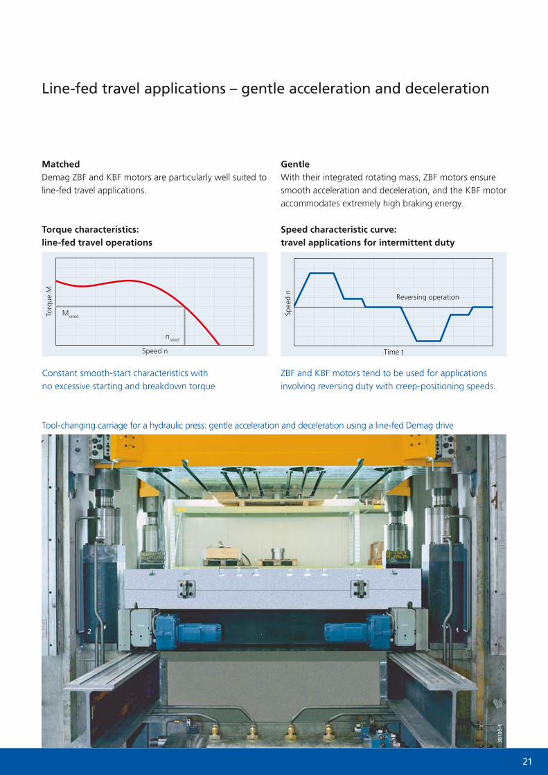
Line-fed travel applications – gentle acceleration and deceleration
Tool-changing carriage for a hydraulic press: gentle acceleration and deceleration using a line-fed Demag drive
Speed characteristic curve: travel applications for intermittent duty
Torque characteristics: line-fed travel operations
MatchedDemag ZBF and KBF motors are particularly well suited to line-fed travel applications.
GentleWith their integrated rotating mass, ZBF motors ensure smooth acceleration and deceleration, and the KBF motor accommodates extremely high braking energy.
3810
5-6
ZBF and KBF motors tend to be used for applications involving reversing duty with creep-positioning speeds.
Constant smooth-start characteristics with no excessive starting and breakdown torque
Time t
Reversing operationSp
eed
n
Torq
ue M
Speed n
Mrated
nrated

22
Travel applications with an inverter – dynamic and smooth
Concrete hopper: using a Demag travel drive with a frequency inverter to ensure smooth acceleration and deceleration
Speed characteristic curve: travel applications for intermittent duty
Torque characteristics: travel with an inverter
DynamicAcceleration and deceleration actions are effected highly dynamically but also very smoothly, even in reversing duty.
SpecificDemag ZBA/ZNA motors have a low internal moment of inertia, which makes them ideal as travel drives in conjunction with a frequency inverter.
399
83-1
9
ZBA/ZNA motors tend to be used for applications involving reversing duty and creep positioning speeds
When using an inverter, it is possible to adjust the characteristic curve, which is optimised for travel applications, as required
Time t
Reversing operation
Spee
d n
Torq
ue M
Speed n
Mrated
nrated range
23
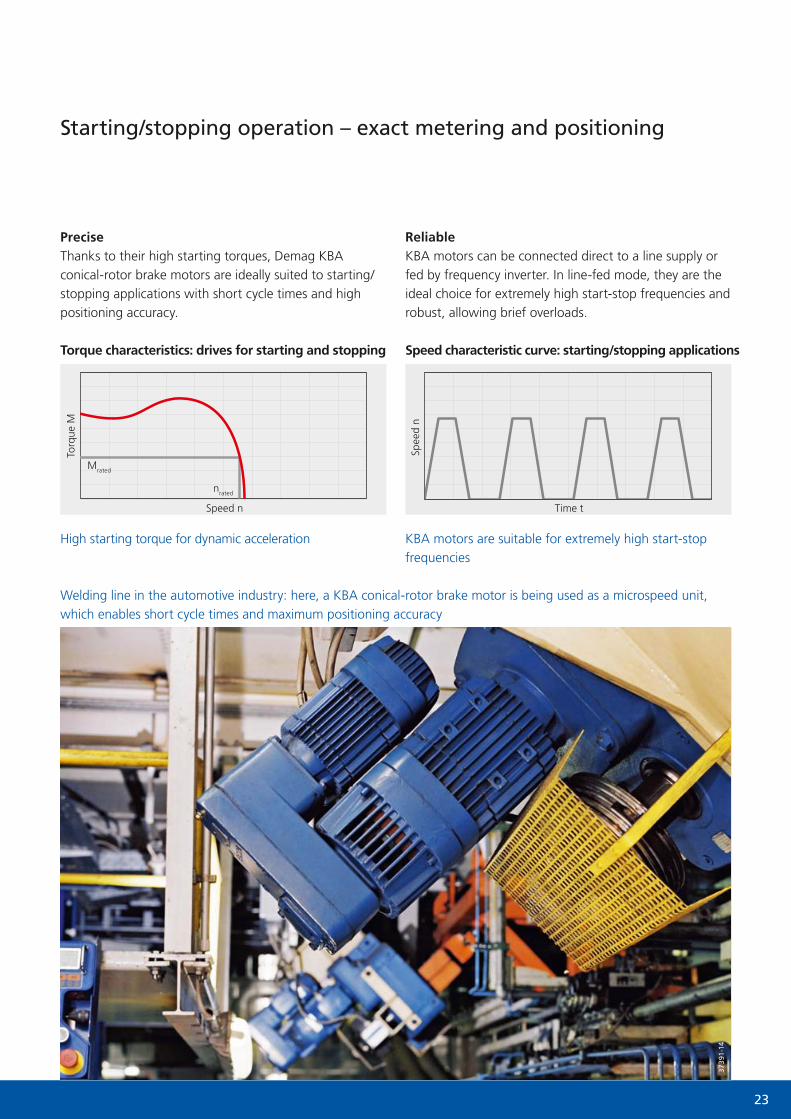
Starting/stopping operation – exact metering and positioning
Speed characteristic curve: starting/stopping applicationsTorque characteristics: drives for starting and stopping
Welding line in the automotive industry: here, a KBA conical-rotor brake motor is being used as a microspeed unit, which enables short cycle times and maximum positioning accuracy
PreciseThanks to their high starting torques, Demag KBA conical-rotor brake motors are ideally suited to starting/stopping applications with short cycle times and high positioning accuracy.
ReliableKBA motors can be connected direct to a line supply or fed by frequency inverter. In line-fed mode, they are the ideal choice for extremely high start-stop frequencies and robust, allowing brief overloads.
3739
1-14
KBA motors are suitable for extremely high start-stop frequencies
High starting torque for dynamic acceleration
Time t
Spee
d n
Torq
ue M
Speed n
Mrated
nrated
24
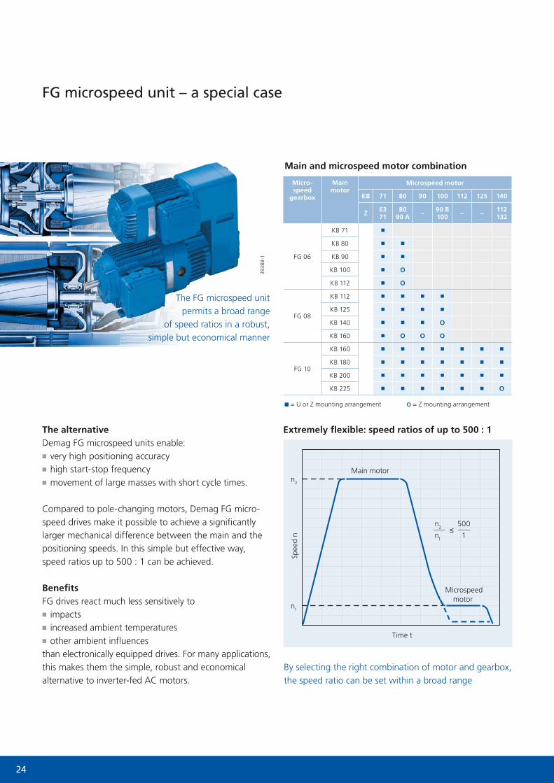
FG microspeed unit – a special case
■ = U or Z mounting arrangement O = Z mounting arrangement
Micro-speed
gearbox
Main motor
Microspeed motor
KB 71 80 90 100 112 125 140
Z 6371
8090 A – 90 B
100 – – 112132
FG 06
KB 71 ■
KB 80 ■ ■
KB 90 ■ ■
KB 100 ■ O
KB 112 ■ O
FG 08
KB 112 ■ ■ ■ ■
KB 125 ■ ■ ■ ■
KB 140 ■ ■ ■ O
KB 160 ■ O O O
FG 10
KB 160 ■ ■ ■ ■ ■ ■ ■
KB 180 ■ ■ ■ ■ ■ ■ ■
KB 200 ■ ■ ■ ■ ■ ■ ■
KB 225 ■ ■ ■ ■ ■ ■ O
Extremely flexible: speed ratios of up to 500 : 1
The FG microspeed unit permits a broad range
of speed ratios in a robust, simple but economical manner
Spee
d n
Time t
Main and microspeed motor combination
Microspeed motor
Main motor
By selecting the right combination of motor and gearbox, the speed ratio can be set within a broad range
n2
n1
n2 500
1≤
n1
The alternativeDemag FG microspeed units enable:
■■ very high positioning accuracy■■ high start-stop frequency■■ movement of large masses with short cycle times.
Compared to pole-changing motors, Demag FG micro-speed drives make it possible to achieve a significantly larger mechanical difference between the main and the positioning speeds. In this simple but effective way, speed ratios up to 500 : 1 can be achieved.
BenefitsFG drives react much less sensitively to
■■ impacts■■ increased ambient temperatures■■ other ambient influences
than electronically equipped drives. For many applications, this makes them the simple, robust and economical alternative to inverter-fed AC motors.
3938
8-1
25
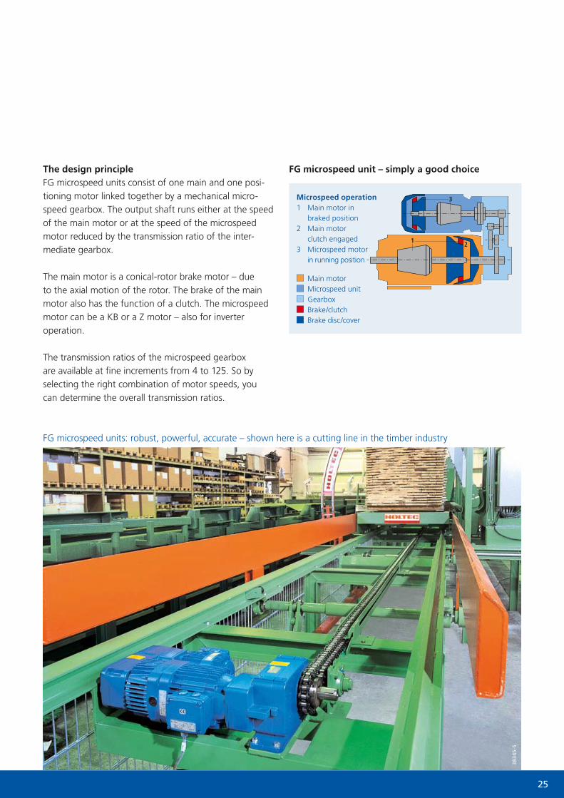
Microspeed operation1 Main motor in
braked position2 Main motor
clutch engaged3 Microspeed motor
in running position
Main motor Microspeed unit Gearbox Brake/clutch Brake disc/cover
FG microspeed units: robust, powerful, accurate – shown here is a cutting line in the timber industry
FG microspeed unit – simply a good choiceThe design principleFG microspeed units consist of one main and one posi-tioning motor linked together by a mechanical micro-speed gearbox. The output shaft runs either at the speed of the main motor or at the speed of the microspeed motor reduced by the transmission ratio of the inter-mediate gearbox.
The main motor is a conical-rotor brake motor – due to the axial motion of the rotor. The brake of the main motor also has the function of a clutch. The microspeed motor can be a KB or a Z motor – also for inverter operation.
The transmission ratios of the microspeed gearbox are available at fine increments from 4 to 125. So by selecting the right combination of motor speeds, you can determine the overall transmission ratios.
383
45-5

26
Tools and services – your contact with us
If you are looking for a partner to provide you with advice and assistance, we will be pleased to assist, whatever the type of drive solution you are developing. From your desk, you can access the tools we have made available.
Geared motor catalogue – open for your needsThis catalogue presents our entire range of geared motors in detail on over 400 pages.
Take advantage of the selection tables to find detailed technical specifications and add optional equipment and accessories.
We will be pleased to support you with comprehensive tools for planning and design

27
CalDrive – open for your demandsYou can use the CalDrive software to calculate suitable drives from the physical parameters you enter. The basic characteristics and data of Demag geared motors and wheel blocks are included in CalDrive. Based on these details, CalDrive will suggest a number of possible solutions for combining the components. The CalDrive software is available at no charge from the internet.
www.drives.demagcranes.com
Drive Designer – open for your ideasUse the Drive Designer to configure geared motors and wheel systems online. You can quickly:
■■ select and configure drives■■ transfer drawings to your design■■ view electrical circuit diagrams■■ download the drives’ technical data.
Drive Designer provides a high degree of convenience:■■ design support with 2D and 3D geometries in all standard data formats
■■ rapid access to technical specifications■■ circuit diagrams for the motors you select■■ display of delivery times■■ transmit your selection to the Demag Shop system.
www.drives.demag-designer.com
Demag Shop – open for businessAfter registering online, you will be sent the access details for the Demag Shop system. In the Shop, you will find the
■■ prices■■ delivery availability ■■ delivery times
relating to the products you need. Order direct and arrange delivery times and shipping method – provided the parts are in stock. You are immediately sent an order confirmation with our order number.
You can, of course, also use the parcel tracking system online in the Demag Shop even if you order the conventional way.
www.demag-shop.de
Circuit diagrams are also generated by the Drive Designer
3D product geometries Individual 2D CAD files

28
0112
EN
20
8 73
4 4
4
701
IS 9
80
No
liabi
lity
for
erro
rs o
r om
issi
ons.
Sub
ject
to
chan
ge.
Prin
ted
in G
erm
any
S+S/
3103
12/1
.5T
www.demagcranes.com