demonstration kit for the st7570 power line modem with ... · pdf filedemonstration kit for...
TRANSCRIPT

November 2011 Doc ID 18032 Rev 2 1/32
UM1008User manual
Demonstration kit for the ST7570 power line modemwith graphical user interface
IntroductionThe ST7570 GUI is a software tool that allows interfacing with one or more STMicroelectronics™ power line modem (PLM) demonstration boards with a personal computer (PC). Only PLM demonstration boards equipped with the ST7570 device are supported.
The ST7570 GUI gives the user complete control of the ST7570 device, having access to all its registers and functions, as described in [2].
The typical application environment (shown in Figure 1) consists of an ST7570 GUI running on a PC and communicating through a USB connection with a PLM demonstration kit equipped with the ST7570 product, such as the EVALKITST7570-1 (consisting of a modem board and a power supply board).
Figure 1. ST7570 typical application environment
www.st.com

Contents UM1008
2/32 Doc ID 18032 Rev 2
Contents
1 Document conventions . . . . . . . . . . . . . . . . . . . . . . . . . . . . . . . . . . . . . . . 4
2 Connection procedure . . . . . . . . . . . . . . . . . . . . . . . . . . . . . . . . . . . . . . . 5
3 GUI installation . . . . . . . . . . . . . . . . . . . . . . . . . . . . . . . . . . . . . . . . . . . . . 9
3.1 System requirements . . . . . . . . . . . . . . . . . . . . . . . . . . . . . . . . . . . . . . . . . 9
3.2 Installing the software . . . . . . . . . . . . . . . . . . . . . . . . . . . . . . . . . . . . . . . . . 9
4 Getting started . . . . . . . . . . . . . . . . . . . . . . . . . . . . . . . . . . . . . . . . . . . . . 12
4.1 Introduction . . . . . . . . . . . . . . . . . . . . . . . . . . . . . . . . . . . . . . . . . . . . . . . 12
4.2 Adding other nodes . . . . . . . . . . . . . . . . . . . . . . . . . . . . . . . . . . . . . . . . . 13
4.3 Opening the COM . . . . . . . . . . . . . . . . . . . . . . . . . . . . . . . . . . . . . . . . . . 14
5 Services . . . . . . . . . . . . . . . . . . . . . . . . . . . . . . . . . . . . . . . . . . . . . . . . . . 17
5.1 Basic modem configuration . . . . . . . . . . . . . . . . . . . . . . . . . . . . . . . . . . . 17
5.2 PHY layer communication . . . . . . . . . . . . . . . . . . . . . . . . . . . . . . . . . . . . 18
5.2.1 Synchro indication information . . . . . . . . . . . . . . . . . . . . . . . . . . . . . . . . 19
5.2.2 PHY data indication information . . . . . . . . . . . . . . . . . . . . . . . . . . . . . . 19
5.2.3 Synchronization management . . . . . . . . . . . . . . . . . . . . . . . . . . . . . . . . 20
5.3 MIB operations . . . . . . . . . . . . . . . . . . . . . . . . . . . . . . . . . . . . . . . . . . . . . 22
5.4 MAC layer communication . . . . . . . . . . . . . . . . . . . . . . . . . . . . . . . . . . . . 24
5.4.1 MAC frame transmission . . . . . . . . . . . . . . . . . . . . . . . . . . . . . . . . . . . . 24
5.4.2 Synchro indication found information . . . . . . . . . . . . . . . . . . . . . . . . . . . 25
5.4.3 MAC data indication information . . . . . . . . . . . . . . . . . . . . . . . . . . . . . . 25
5.4.4 Synchronization management notification . . . . . . . . . . . . . . . . . . . . . . . 25
5.4.5 Statistic information . . . . . . . . . . . . . . . . . . . . . . . . . . . . . . . . . . . . . . . . 26
5.5 Alarm services . . . . . . . . . . . . . . . . . . . . . . . . . . . . . . . . . . . . . . . . . . . . . 26
5.6 Repeater Call . . . . . . . . . . . . . . . . . . . . . . . . . . . . . . . . . . . . . . . . . . . . . . 27
5.6.1 Repeater Call for client nodes . . . . . . . . . . . . . . . . . . . . . . . . . . . . . . . . 28
5.6.2 Repeater Call for server nodes . . . . . . . . . . . . . . . . . . . . . . . . . . . . . . . 28
6 References . . . . . . . . . . . . . . . . . . . . . . . . . . . . . . . . . . . . . . . . . . . . . . . . 30
7 Revision history . . . . . . . . . . . . . . . . . . . . . . . . . . . . . . . . . . . . . . . . . . . 31

UM1008 List of figures
Doc ID 18032 Rev 2 3/32
List of figures
Figure 1. ST7570 typical application environment . . . . . . . . . . . . . . . . . . . . . . . . . . . . . . . . . . . . . . . . 1Figure 2. Hardware update wizard screen . . . . . . . . . . . . . . . . . . . . . . . . . . . . . . . . . . . . . . . . . . . . . . 5Figure 3. New hardware update wizard . . . . . . . . . . . . . . . . . . . . . . . . . . . . . . . . . . . . . . . . . . . . . . . . 6Figure 4. Found new hardware update wizard. . . . . . . . . . . . . . . . . . . . . . . . . . . . . . . . . . . . . . . . . . . 6Figure 5. Hardware installation . . . . . . . . . . . . . . . . . . . . . . . . . . . . . . . . . . . . . . . . . . . . . . . . . . . . . . 7Figure 6. Software installation . . . . . . . . . . . . . . . . . . . . . . . . . . . . . . . . . . . . . . . . . . . . . . . . . . . . . . . 7Figure 7. Completing the found new hardware update wizard. . . . . . . . . . . . . . . . . . . . . . . . . . . . . . . 8Figure 8. ST7570 GUI installation wizard . . . . . . . . . . . . . . . . . . . . . . . . . . . . . . . . . . . . . . . . . . . . . . 9Figure 9. ST7570 GUI setup . . . . . . . . . . . . . . . . . . . . . . . . . . . . . . . . . . . . . . . . . . . . . . . . . . . . . . . 10Figure 10. Application installation . . . . . . . . . . . . . . . . . . . . . . . . . . . . . . . . . . . . . . . . . . . . . . . . . . . . 10Figure 11. Application installed . . . . . . . . . . . . . . . . . . . . . . . . . . . . . . . . . . . . . . . . . . . . . . . . . . . . . . 11Figure 12. ST7570 GUI main window . . . . . . . . . . . . . . . . . . . . . . . . . . . . . . . . . . . . . . . . . . . . . . . . . 12Figure 13. ST7570 GUI tooltip example. . . . . . . . . . . . . . . . . . . . . . . . . . . . . . . . . . . . . . . . . . . . . . . . 13Figure 14. “Add node” procedure to add a new node . . . . . . . . . . . . . . . . . . . . . . . . . . . . . . . . . . . . . 13Figure 15. The new node has been added - (panel Node 2) is now available . . . . . . . . . . . . . . . . . . . 13Figure 16. Modem connection procedure . . . . . . . . . . . . . . . . . . . . . . . . . . . . . . . . . . . . . . . . . . . . . . 14Figure 17. Modem connection success . . . . . . . . . . . . . . . . . . . . . . . . . . . . . . . . . . . . . . . . . . . . . . . . 14Figure 18. Start the automatic COM port number detection procedure . . . . . . . . . . . . . . . . . . . . . . . . 15Figure 19. Automatic COM port number detection procedure: step 1 . . . . . . . . . . . . . . . . . . . . . . . . . 15Figure 20. Automatic COM port number detection procedure: step 2 . . . . . . . . . . . . . . . . . . . . . . . . . 15Figure 21. Automatic COM port number detection procedure: final step . . . . . . . . . . . . . . . . . . . . . . . 16Figure 22. Modem configuration . . . . . . . . . . . . . . . . . . . . . . . . . . . . . . . . . . . . . . . . . . . . . . . . . . . . . 17Figure 23. PHY power line transmission . . . . . . . . . . . . . . . . . . . . . . . . . . . . . . . . . . . . . . . . . . . . . . . 18Figure 24. Communication notifications. . . . . . . . . . . . . . . . . . . . . . . . . . . . . . . . . . . . . . . . . . . . . . . . 18Figure 25. Synchro Indication information . . . . . . . . . . . . . . . . . . . . . . . . . . . . . . . . . . . . . . . . . . . . . . 19Figure 26. Data indication information . . . . . . . . . . . . . . . . . . . . . . . . . . . . . . . . . . . . . . . . . . . . . . . . . 20Figure 27. Synchronization status information. . . . . . . . . . . . . . . . . . . . . . . . . . . . . . . . . . . . . . . . . . . 21Figure 28. Synchronization reject request command. . . . . . . . . . . . . . . . . . . . . . . . . . . . . . . . . . . . . . 21Figure 29. MIB parameter panel default appearance . . . . . . . . . . . . . . . . . . . . . . . . . . . . . . . . . . . . . 22Figure 30. MAC layer configuration parameters . . . . . . . . . . . . . . . . . . . . . . . . . . . . . . . . . . . . . . . . . 23Figure 31. MIB object writing and reading . . . . . . . . . . . . . . . . . . . . . . . . . . . . . . . . . . . . . . . . . . . . . . 23Figure 32. MIB object writing and reading: console messages . . . . . . . . . . . . . . . . . . . . . . . . . . . . . . 23Figure 33. MAC layer frame composition. . . . . . . . . . . . . . . . . . . . . . . . . . . . . . . . . . . . . . . . . . . . . . . 24Figure 34. MAC communication notifications. . . . . . . . . . . . . . . . . . . . . . . . . . . . . . . . . . . . . . . . . . . . 24Figure 35. Synchro indication found information . . . . . . . . . . . . . . . . . . . . . . . . . . . . . . . . . . . . . . . . . 25Figure 36. Data indication information . . . . . . . . . . . . . . . . . . . . . . . . . . . . . . . . . . . . . . . . . . . . . . . . . 25Figure 37. Synchro indication lost information . . . . . . . . . . . . . . . . . . . . . . . . . . . . . . . . . . . . . . . . . . . 25Figure 38. MAC statistic information counters . . . . . . . . . . . . . . . . . . . . . . . . . . . . . . . . . . . . . . . . . . . 26Figure 39. Alarm service settings. . . . . . . . . . . . . . . . . . . . . . . . . . . . . . . . . . . . . . . . . . . . . . . . . . . . . 26Figure 40. Alarm service notifications . . . . . . . . . . . . . . . . . . . . . . . . . . . . . . . . . . . . . . . . . . . . . . . . . 27Figure 41. Alarm counters controls . . . . . . . . . . . . . . . . . . . . . . . . . . . . . . . . . . . . . . . . . . . . . . . . . . . 27Figure 42. RC request catch setting . . . . . . . . . . . . . . . . . . . . . . . . . . . . . . . . . . . . . . . . . . . . . . . . . . 27Figure 43. Repeater Call request for client . . . . . . . . . . . . . . . . . . . . . . . . . . . . . . . . . . . . . . . . . . . . . 28Figure 44. Repeater settings for server node . . . . . . . . . . . . . . . . . . . . . . . . . . . . . . . . . . . . . . . . . . . 28Figure 45. RC confirm for server node. . . . . . . . . . . . . . . . . . . . . . . . . . . . . . . . . . . . . . . . . . . . . . . . . 29

Document conventions UM1008
4/32 Doc ID 18032 Rev 2
1 Document conventions
The following abbreviations are used:
Table 1. List of abbreviations
Abbreviation Description
PRE Preamble
SSD Start of Subframe Delimitation
MIB Management Information Base
PGA Programmable Gain Amplifier
ZC Zero-crossing
PHY Physical Layer
MAC Medium Access Layer
DA Destination Address
SA Source Address
NS Number of Subframes
FCS Frame Check Sequence
CRC Cyclic Redundancy Check
M_sdu MAC service data unit
M_pdu MAC protocol data unit
IC Initial Credit
CC Current Credit
DC Delta Credit
TIC Inter-character Timeout
FIMA First Initiator MAC Address
LIMA Last Initiator MAC Address
RC Repeater call procedure
IS Intelligent Synchronization procedure

UM1008 Connection procedure
Doc ID 18032 Rev 2 5/32
2 Connection procedure
In order to connect EVALKITST7570-1 to the PC, the user must follow the instructions below:
1. Connect the board to the PC using a USB cable.
2. Plug a power cable into the board AC power plug.
3. Plug the power cable into the power socket.
4. As soon as the board is powered, the power LEDs switch on.
USB/UART adapter driver installation
The USB communication between the EVALKITST7570-1 and the PC is managed through an onboard USB to UART adapter. This device needs the installation of the correct device software driver on the PC.
Assuming that the device drivers are not yet installed, follow the instructions below:
1. Download the latest available Virtual COM Port (VCP) drivers from the FTDI web site (www.ftdichip.com) and unzip them to a location on the host PC.
2. Connect the EVALKITST7570-1 to a spare USB port on the host PC. The screen shown in Figure 2 is displayed. Select “No, not this time” from the options available and then click “Next” to proceed with the installation.
Figure 2. Hardware update wizard screen

Connection procedure UM1008
6/32 Doc ID 18032 Rev 2
3. Select “Install from a list or specific location (Advanced)”, as shown in Figure 3 below and then click “Next”.
Figure 3. New hardware update wizard
4. Select “Search for the best driver in these locations” and enter the file path in the combo-box (“C:\CDM 2.02.04", in the example shown in Figure 4) or browse to it by clicking “Browse”. Once the file path has been entered in the box, click “Next” to proceed.
Figure 4. Found new hardware update wizard
UM1008 Connection procedure
Doc ID 18032 Rev 2 7/32
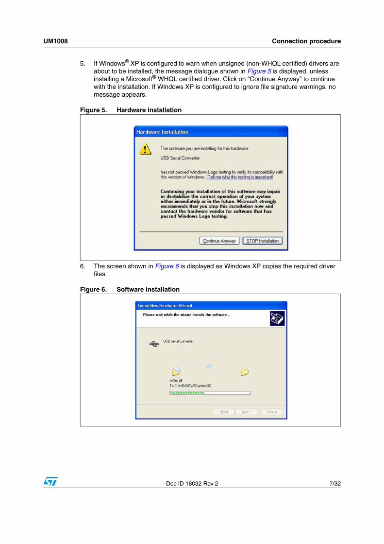
5. If Windows® XP is configured to warn when unsigned (non-WHQL certified) drivers are about to be installed, the message dialogue shown in Figure 5 is displayed, unless installing a Microsoft® WHQL certified driver. Click on “Continue Anyway” to continue with the installation. If Windows XP is configured to ignore file signature warnings, no message appears.
Figure 5. Hardware installation
6. The screen shown in Figure 6 is displayed as Windows XP copies the required driver files.
Figure 6. Software installation
Connection procedure UM1008
8/32 Doc ID 18032 Rev 2
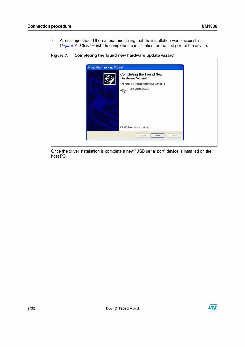
7. A message should then appear indicating that the installation was successful (Figure 7). Click “Finish” to complete the installation for the first port of the device.
Figure 7. Completing the found new hardware update wizard
Once the driver installation is complete a new “USB serial port” device is installed on the host PC.

UM1008 GUI installation
Doc ID 18032 Rev 2 9/32
3 GUI installation
3.1 System requirementsA personal computer (PC) including:
● Windows NT/2000/XP operating system
● A hard disk with at least 15 MBytes of free space to install the GUI
● One or more USB 1.1 ports
3.2 Installing the softwareFollow the instructions below to install the ST7570 GUI software.
1. Extract the contents of the archive in a new directory.
2. Launch “setup.exe” to start the install procedure.
3. Press the “Next” button (Figure 8).
Figure 8. ST7570 GUI installation wizard

GUI installation UM1008
10/32 Doc ID 18032 Rev 2
4. Choose an installation path (the default path is suggested) and press the “Next” button (Figure 9).
Figure 9. ST7570 GUI setup
5. Press the “Next” button to start the installation (Figure 10).
Figure 10. Application installation

UM1008 GUI installation
Doc ID 18032 Rev 2 11/32
6. Once installation has completed, press the “Finish” button to complete the process (Figure 11).
Figure 11. Application installed

Getting started UM1008
12/32 Doc ID 18032 Rev 2
4 Getting started
4.1 IntroductionThe ST7570 GUI gives the user complete control of the ST7570 device, with full access to all the settings and functions described in [1.]. The GUI can be used to:
● Establish a connection to the ST7570 modem
● Configure the ST7570 and manage all its settings
● Perform any transmission and reception of data and alarms over the power line
Figure 12 shows the main window of the ST7570 GUI. The panel is divided into two sections:
1. Node panel: used to control an ST7570 node. In case of multiple nodes connected to the GUI, the user can switch between the panels through the node panel tabs.
2. Console: box displaying where all the messages exchanged with the node are displayed. In the case of multiple nodes, this panel is common to all the nodes.
Figure 12. ST7570 GUI main window
Almost all graphical interface objects and relative controls show their tooltips, when the user hovers the cursor over this item: these tooltips give information about the meaning and the use of the controls and parameters.

UM1008 Getting started
Doc ID 18032 Rev 2 13/32
Figure 13. ST7570 GUI tooltip example
4.2 Adding other nodesBy default, the GUI shows only one node tab in the panel (“Node 1" in Figure 12). Nevertheless, a single instance of the ST7570 GUI can control more nodes if needed. To add a new node, left-click on the “Main” menu and then select the menu item “Add node” (Figure 14).
Figure 14. “Add node” procedure to add a new node
As a result, a new panel tab appears (with tab “Node 2" in Figure 15).
Figure 15. The new node has been added - (panel Node 2) is now available
Getting started UM1008
14/32 Doc ID 18032 Rev 2
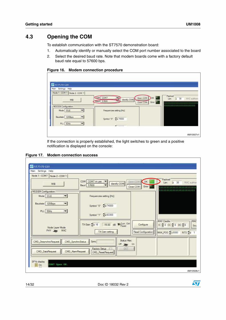
4.3 Opening the COMTo establish communication with the ST7570 demonstration board:
1. Automatically identify or manually select the COM port number associated to the board
2. Select the desired baud rate. Note that modem boards come with a factory default baud rate equal to 57600 bps.
Figure 16. Modem connection procedure
If the connection is properly established, the light switches to green and a positive notification is displayed on the console:
Figure 17. Modem connection success

UM1008 Getting started
Doc ID 18032 Rev 2 15/32
Automatic COM port number detection
This guided procedure allows the user to simply identify the COM port number related to the board they would like to connect with. As indicated in Figure 18, the “Identify COM” button in the node panel must be pressed:
Figure 18. Start the automatic COM port number detection procedure
First of all, the procedure invites the user to remove the desired modem's USB cable:
Figure 19. Automatic COM port number detection procedure: step 1
Then the user should plug in the USB cable:
Figure 20. Automatic COM port number detection procedure: step 2

Getting started UM1008
16/32 Doc ID 18032 Rev 2
The automatic procedure stops communicating the detected COM number and sets this value in the relative control:
Figure 21. Automatic COM port number detection procedure: final step

UM1008 Services
Doc ID 18032 Rev 2 17/32
5 Services
5.1 Basic modem configurationAt power-on, the modem is in IDLE state (refer to [2.]).
In order to perform communication on the power line, the modem must be configured through the “Configure” button.
This command groups all the basic operating settings of the modem, as resumed in MIB 0x00A1 object (“PLC Configuration”):
● Operating mode
● Bit rate
● Mains frequency
● Transmission gain
● Channel frequencies
● Access layer mode
● Current control
A confirmation (positive or negative) appears on the console notifying that either the configuration required has been successfully set or an error has occurred (Figure 22).
Figure 22. Modem configuration
In PHY operating mode, these are all the configuration settings needed to perform transmission and reception on the power line.

Services UM1008
18/32 Doc ID 18032 Rev 2
5.2 PHY layer communicationIn order to perform power line communication between two modems:
1. Open two COM ports, as described in Section 5.3.
2. Configure the modems, as described inSection 6.1 (first node as PHY client, second node as PHY server).
3. Customize (if desired) the payload to be transmitted.
4. Press the CMD_DataRequest button.
Figure 23. PHY power line transmission
If the communication is correctly performed, the console displays the successful Data Confirm notification in the client side and the Synchro and Data Indication notifications in the server side.
5. This basic communication test has the same steps as the test described in [2.].
Figure 24. Communication notifications

UM1008 Services
Doc ID 18032 Rev 2 19/32
5.2.1 Synchro indication information
As soon as a valid PRE+SSD has been received by the ST7570, the GUI displays a CMD_SynchroIndication notification in the console box with the related information regarding signal and noise levels, electrical phase and embedded PGA code.
Figure 25 presents the graphical format of the Synchro Indication notification, and it shows how to decode the values displayed of signal and noise levels, electrical phase and PGA code.
Figure 25. Synchro Indication information
5.2.2 PHY data indication information
In PHY mode, the Data Indication exchanged from ST7570 to the PC host gives information about the payload of the received frame, the levels of signal and noise estimated during frame reception, and some statistical information about the demodulation procedure.
Figure 26 shows how the ST7570 GUI presents the PHY Data Indication.

Services UM1008
20/32 Doc ID 18032 Rev 2
Figure 26. Data indication information
5.2.3 Synchronization management
A client modem acquires the timeslot synchronization as soon as a frame is either transmitted or received; a server node is not allowed to transmit if not synchronized, and synchronization can be achieved through a valid reception only.
CMD_SynchroStatus
In the Node tab, the CMD_SynchroStatus button can be used to know the synchronization status of the modem, as it implements the CMD_SyncroStatus command [2.].
Both console and “Sync” box show the modem status: Found(1) or NotFound(2) are the possible answers, as in Figure 27.

UM1008 Services
Doc ID 18032 Rev 2 21/32
Figure 27. Synchronization status information
CMD_DesynchroRequest
It is possible to force a rejection of the synchronization through the dedicated command CMD_DesynchroRequest. When pressed, the CMD_DesynchroRequest button in the node tab allows this request to be sent. The execution of this command does not generate any answer notification and, therefore, the console does not show any message.
Figure 28. Synchronization reject request command
Services UM1008
22/32 Doc ID 18032 Rev 2
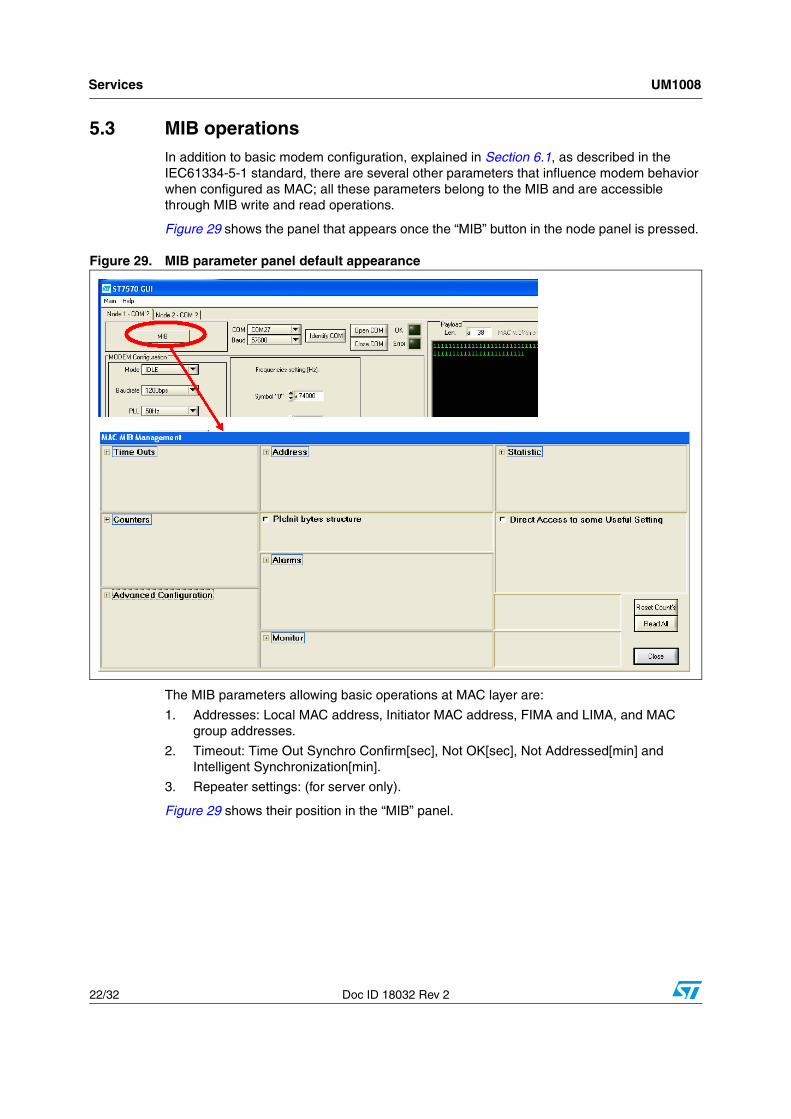
5.3 MIB operationsIn addition to basic modem configuration, explained in Section 6.1, as described in the IEC61334-5-1 standard, there are several other parameters that influence modem behavior when configured as MAC; all these parameters belong to the MIB and are accessible through MIB write and read operations.
Figure 29 shows the panel that appears once the “MIB” button in the node panel is pressed.
Figure 29. MIB parameter panel default appearance
The MIB parameters allowing basic operations at MAC layer are:
1. Addresses: Local MAC address, Initiator MAC address, FIMA and LIMA, and MAC group addresses.
2. Timeout: Time Out Synchro Confirm[sec], Not OK[sec], Not Addressed[min] and Intelligent Synchronization[min].
3. Repeater settings: (for server only).
Figure 29 shows their position in the “MIB” panel.

UM1008 Services
Doc ID 18032 Rev 2 23/32
Figure 30. MAC layer configuration parameters
The MIB panel allows to write and read all the MIB objects listed and described in [2.]. The object name used in the label is the same as in [2.] and the object index is shown on the tooltip.
For all MIB objects, the “W” button close to the corresponding box name allows to write the value set in the box in the ST7570 registers. On the other hand, the “R” button reports the current value stored in the ST7570 registers and it is displayed in the corresponding box name.
Figure 31. MIB object writing and reading
The GUI console displays the result of both operations, as in Figure 32:
Figure 32. MIB object writing and reading: console messages

Services UM1008
24/32 Doc ID 18032 Rev 2
5.4 MAC layer communicationIn order to perform communication in MAC mode, follow the steps listed in Section 6.2 making sure the operating mode is set to MAC instead of PHY.
5.4.1 MAC frame transmission
As described in [3.],the standard MAC frame is made up of several parameters that can be set directly in the GUI, as shown in Figure 33. When the CMD_DataRequest button is pressed (i.e. the user is requesting a packet transmission), the ST7570 GUI software sends a proper command to the modem with the parameters values.
Figure 33. MAC layer frame composition
If the communication is correctly performed, the console displays the successful Data Confirm notification in the client side and the Synchro Found and Data Indication notifications in the server side.
Figure 34. MAC communication notifications

UM1008 Services
Doc ID 18032 Rev 2 25/32
5.4.2 Synchro indication found information
All the additional information provided in this notification has the same meaning as in the PHY layer and is explained in Section 6.2.1.
Figure 35. Synchro indication found information
5.4.3 MAC data indication information
This notification contains standard information (specified in IEC61334-5-1) and additional information about the frame credits and the eventual padding.
Figure 36. Data indication information
5.4.4 Synchronization management notification
Figure 37 shows an example of the synchronization lost notification.
All the related fields are coded in accordance with [2.].
Figure 37. Synchro indication lost information

Services UM1008
26/32 Doc ID 18032 Rev 2
5.4.5 Statistic information
Several MIB variables (accessible through indexed MIB write and read operations) allow a complete analysis of the communicating behavior and performance of the modem set in MAC mode.
The writing operation on these statistic variables causes a reset to default values and the Reset Count's button resets all the counter values.
Figure 38. MAC statistic information counters
5.5 Alarm servicesOnce synchronized, the node can transmit, receive, and repeat alarms according to the settings stored in the following MIB objects:
1. Alarm Repetition number, Alarm Before Indication number, Alarm Reject Window number: MIB object 0085h in [2.].
2. Disable Alarm Indication, Disable Alarm Repetition, Disable Alarm SN Indication: MIB object 0086h in [2.].
Figure 39. Alarm service settings
UM1008 Services
Doc ID 18032 Rev 2 27/32
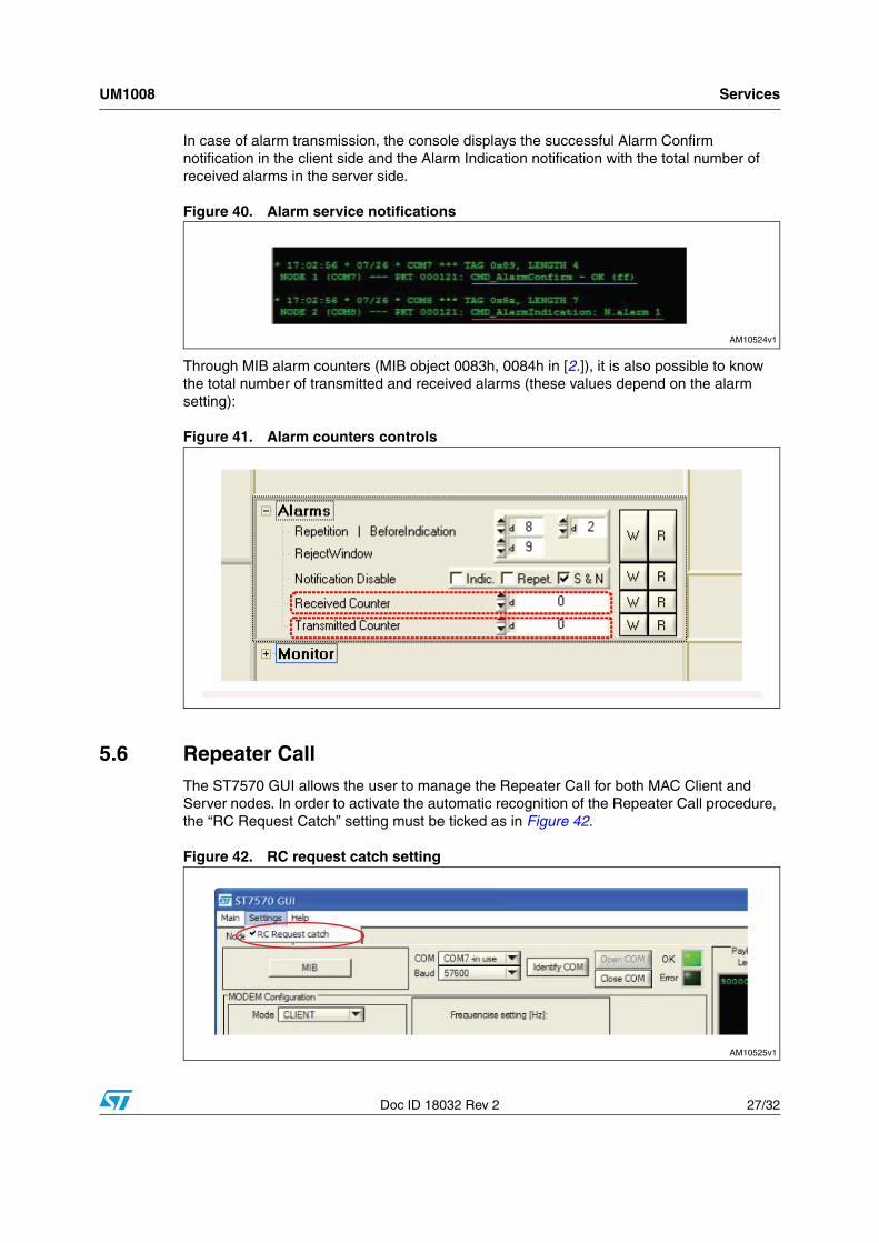
In case of alarm transmission, the console displays the successful Alarm Confirm notification in the client side and the Alarm Indication notification with the total number of received alarms in the server side.
Figure 40. Alarm service notifications
Through MIB alarm counters (MIB object 0083h, 0084h in [2.]), it is also possible to know the total number of transmitted and received alarms (these values depend on the alarm setting):
Figure 41. Alarm counters controls
5.6 Repeater CallThe ST7570 GUI allows the user to manage the Repeater Call for both MAC Client and Server nodes. In order to activate the automatic recognition of the Repeater Call procedure, the “RC Request Catch” setting must be ticked as in Figure 42.
Figure 42. RC request catch setting

Services UM1008
28/32 Doc ID 18032 Rev 2
5.6.1 Repeater Call for client nodes
The Repeater Call service is started by a Client node in accordance with the details presented in [2]. By pressing the CMD_RC Request button with the parameters presented in Figure 43 properly filled, the GUI performs both operations:
● send a MAC data request command to the connected modem following the upper protocol layer specifications for Data Payload; the Payload window automatically switches to the RC Request (BASIC) item; the data transmission takes into account the credit parameters expressed in the GUI (the IC parameter must be greater than 0 so that the modem can accept the RC Request)
● send an RC Request to the modem while powerline transmission is in progress to respect the RC mechanism, with the TX_POS, RC_THRESHOLD parameters expressed in the GUI.
Figure 43. Repeater Call request for client
5.6.2 Repeater Call for server nodes
In order to activate the Repeater Call service for server nodes, the MIB object 000Bh (repeater settings) must be written to either a “No” or “Yes” value through the referred ring menu from the MIB panel, as in Figure 44.
Figure 44. Repeater settings for server node
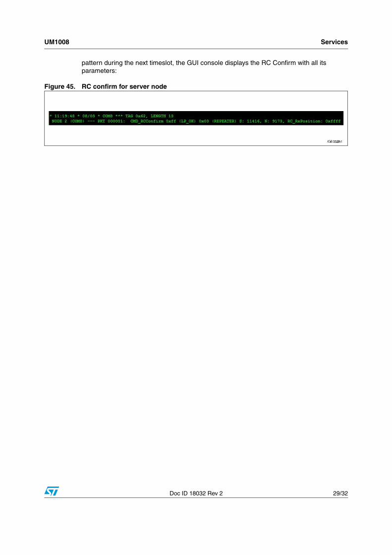
After a valid reception of a MAC frame properly filled to announce the Repeater Call mechanism (as the one sent by the Client in Section 5.6.1), if the Server receives an RC
UM1008 Services
Doc ID 18032 Rev 2 29/32
pattern during the next timeslot, the GUI console displays the RC Confirm with all its parameters:
Figure 45. RC confirm for server node

References UM1008
30/32 Doc ID 18032 Rev 2
6 References
1. STMicroelectronics, ST7570; S-FSK power line networking system-on-chip, datasheet
2. STMicroelectronics, UM0934; FSK, PSK Multi-Mode Power Line Networking System On Chip, user manual
3. International Electrotechnical Commission (IEC), IEC 61334-5-1 ed2.0, www.iec.ch
UM1008 Revision history
Doc ID 18032 Rev 2 31/32
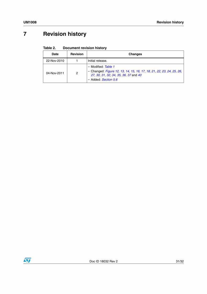
7 Revision history
Table 2. Document revision history
Date Revision Changes
22-Nov-2010 1 Initial release.
04-Nov-2011 2
– Modified: Table 1– Changed: Figure 12, 13, 14, 15, 16, 17, 18, 21, 22, 23, 24, 25, 26,
27, 30, 31, 32, 34, 35, 36, 37 and 40– Added: Section 5.6

UM1008
32/32 Doc ID 18032 Rev 2
Please Read Carefully:
Information in this document is provided solely in connection with ST products. STMicroelectronics NV and its subsidiaries (“ST”) reserve theright to make changes, corrections, modifications or improvements, to this document, and the products and services described herein at anytime, without notice.
All ST products are sold pursuant to ST’s terms and conditions of sale.
Purchasers are solely responsible for the choice, selection and use of the ST products and services described herein, and ST assumes noliability whatsoever relating to the choice, selection or use of the ST products and services described herein.
No license, express or implied, by estoppel or otherwise, to any intellectual property rights is granted under this document. If any part of thisdocument refers to any third party products or services it shall not be deemed a license grant by ST for the use of such third party productsor services, or any intellectual property contained therein or considered as a warranty covering the use in any manner whatsoever of suchthird party products or services or any intellectual property contained therein.
UNLESS OTHERWISE SET FORTH IN ST’S TERMS AND CONDITIONS OF SALE ST DISCLAIMS ANY EXPRESS OR IMPLIEDWARRANTY WITH RESPECT TO THE USE AND/OR SALE OF ST PRODUCTS INCLUDING WITHOUT LIMITATION IMPLIEDWARRANTIES OF MERCHANTABILITY, FITNESS FOR A PARTICULAR PURPOSE (AND THEIR EQUIVALENTS UNDER THE LAWSOF ANY JURISDICTION), OR INFRINGEMENT OF ANY PATENT, COPYRIGHT OR OTHER INTELLECTUAL PROPERTY RIGHT.
UNLESS EXPRESSLY APPROVED IN WRITING BY TWO AUTHORIZED ST REPRESENTATIVES, ST PRODUCTS ARE NOTRECOMMENDED, AUTHORIZED OR WARRANTED FOR USE IN MILITARY, AIR CRAFT, SPACE, LIFE SAVING, OR LIFE SUSTAININGAPPLICATIONS, NOR IN PRODUCTS OR SYSTEMS WHERE FAILURE OR MALFUNCTION MAY RESULT IN PERSONAL INJURY,DEATH, OR SEVERE PROPERTY OR ENVIRONMENTAL DAMAGE. ST PRODUCTS WHICH ARE NOT SPECIFIED AS "AUTOMOTIVEGRADE" MAY ONLY BE USED IN AUTOMOTIVE APPLICATIONS AT USER’S OWN RISK.
Resale of ST products with provisions different from the statements and/or technical features set forth in this document shall immediately voidany warranty granted by ST for the ST product or service described herein and shall not create or extend in any manner whatsoever, anyliability of ST.
ST and the ST logo are trademarks or registered trademarks of ST in various countries.
Information in this document supersedes and replaces all information previously supplied.
The ST logo is a registered trademark of STMicroelectronics. All other names are the property of their respective owners.
© 2011 STMicroelectronics - All rights reserved
STMicroelectronics group of companies
Australia - Belgium - Brazil - Canada - China - Czech Republic - Finland - France - Germany - Hong Kong - India - Israel - Italy - Japan - Malaysia - Malta - Morocco - Philippines - Singapore - Spain - Sweden - Switzerland - United Kingdom - United States of America
www.st.com