densification and geometrical assessments of alumina parts
TRANSCRIPT

Strojniški vestnik - Journal of Mechanical Engineering 59(2013)11, 646-661 Received for review: 2013-01-22© 2013 Journal of Mechanical Engineering. All rights reserved. Received revised form: 2013-04-19DOI:10.5545/sv-jme.2013.998 Special Issue, Original Scientific Paper Accepted for publication: 2013-05-06
*Corr. Author’s Address: Department of Mechanical Engineering, Celestijnenlaan 300B, 3001 Heverlee, Belgium, [email protected]
0 INTRODUCTION
0.1 AM of Polystyrene
Polystyrene is one of the most popular polymers used in additive manufacturing (AM) technology. It has been used to demonstrate newly developed AM technologies, such as layered electro-photographic printing by Cormier et al. [1], selective inhibition sintering by Khoshnevis et al. [2] or various kinds of laminated object manufacturing (LOM) technologies (Brooks and Aitchison [3], de Smit and Broek [4], or Mahale et al. [5]). Moreover, polystyrene has been used to demonstrate that AM technologies can improve the investment-casting (IC) process by reducing tooling costs and production lead-times (Cheah et al. [6]).
The combined use of AM technology and investment-casting technology is called ‘rapid investment casting’. As illustrated by Cheah et al. [6], two main application areas exist: 1) AM technology can be applied to produce inserts to injection mould polystyrene parts, as illustrated by Kinsella et al. [7]; 2) AM technologies can be applied to produce polystyrene IC patterns. These patterns can be master patterns (e.g. for silicone rubber moulding), but are mostly sacrificial patterns.
Amorphous polystyrene is more suitable than other (semi-crystalline) polymer materials for the production of sacrificial rapid investment casting patterns due to its geometrical stability during the burning out step of the IC process (Kruth et al. [8]). This stability results from the polystyrene patterns’ porosity and low thermal expansion that prevents breaking of the (ceramic) IC mould during burn out.
The polystyrene sacrificial patterns are sometimes produced through three-dimensional printing (3DP) (Levy et al. [9]), but mainly through SLS®. In order to increase the polystyrene pattern’s strength, AM of high quality polystyrenes is investigated (e.g. SLS® of high impact polystyrene by Yang et al. [10]) and/or wax infiltration of the patterns is applied (Ku et al. [11]). Wax infiltration of the polystyrene parts can also seal surface porosities (Cheah et al. [6]).
A distinction must be made between the production of metal and ceramic parts through rapid investment casting with (polystyrene) sacrificial patterns. When producing metal parts, the sacrificial polystyrene patterns have the shape of the part to be produced. From the sacrificial pattern, a plaster mould (see Liu et al. [12] or Niino and Yamada [13]), but generally a ceramic moulding shell is sometimes fabricated. Finally, the moulds are used to fabricate the metal parts through a casting process, e.g. vacuum pressure casting of aluminium parts, as applied by Hongjun et al. [14]. Applications of this technology can be found in the production of titanium, aluminium, steel alloys or super alloys for competitive motorsports (Cevolinni et al. [15]). When producing ceramic parts, the sacrificial polystyrene patterns have the negative geometry of the parts to be produced. Through high pressure slip casting, followed by debinding of the polystyrene and a furnace sintering treatment, Si3N4 parts can be obtained (Pfeifer et al. [16]).
0.2 AM of Ceramics through Indirect SLS® of Dry Composite Powders
Selective laser sintering (SLS®) is one of the additive manufacturing processes capable of producing
Densification and Geometrical Assessments of Alumina Parts Produced Through Indirect Selective Laser Sintering of
Alumina-Polystyrene Composite PowderDeckers, J. – Kruth, J.-P. – Cardon, L. – Shahzad, K. – Vleugels, J.
Jan Deckers1,* – Jean-Pierre Kruth1 – Ludwig Cardon2 – Khuram Shahzad3 – Jef Vleugels3
1 Catholic University of Leuven, Department of Mechanical Engineering, Belgium 2 University College Ghent, Associated Faculty of Applied Engineering Sciences, Belgium
3 Catholic University of Leuven, Department of Metallurgy and Materials Engineering, Belgium
A powder metallurgy (PM) process to fabricate alumina parts through indirect selective laser sintering (SLS®) of alumina-polystyrene composite powder particles is presented. The PM process includes powder production through dispersion polymerisation, SLS®, debinding and solid-state sintering. Dimensional changes, which occur during the debinding and solid-state sintering, are assessed. Warm isostatic pressing (WIP) and both pressureless and pressure infiltration are introduced as extra steps of the PM process chain. The influence of WIP and the infiltration steps on the changes in density, geometry and microstructure during the PM process are investigated.Keywords: additive manufacturing, ceramic, indirect selective laser sintering, alumina, polystyrene

Strojniški vestnik - Journal of Mechanical Engineering 59(2013)11, 646-661
647Densification and Geometrical Assessments of Alumina Parts Produced Through Indirect Selective Laser Sintering of Alumina-Polystyrene Composite Powder
macroscopic ceramic parts. SLS® of ceramic components can be done directly or indirectly. Indirect selective laser sintering, the AM technology that is applied in this paper, involves the melting of a sacrificial organic binder phase to produce ‘green parts’, i.e. parts consisting of a binder phase that holds the ceramic particles together. If the binder is organic, it can be removed after the laser sintering step. In this way a ‘brown part’ is obtained. In the last step, the density and strength of the brown part is improved by solid-state sintering (SSS) in a furnace or through another densification processes. Direct selective laser sintering does not involve a sacrificial binder phase and the ceramic material is directly sintered or melted to produce parts (see Kruth et al. [17], Dewidar et al. [18]).
Indirect SLS® makes use of either dry powders, deposited by, for example, a counter-rolling roller, or powder-containing slurries that are dried after deposition before laser scanning (Tang et al. [19]). In this paper, indirect SLS® of dry powders is investigated. The counter-rolling roller of a DTM Sinterstation 2000 is used to deposit the produced composite powder.
Different types of binders have already been examined to fabricate many ceramic parts via indirect SLS® (Fig. 1). If the binder is organic, it cannot be burned. During the thermal treatment, the inorganic binder (e.g. HBO2) chemically reacts and becomes part of the structural ceramic (e.g. B2O3) (Lee [20] and [21]). Different types of organic binders have already been examined to fabricate ceramic parts via SLS®:• waxes: e.g. stearic acid (Liu et al. [22] and Leu et
al. [23]),
• thermosets such as phenolic resin (Liu et al. [24]), epoxy resin (e.g. Evans [25] and Stevinson et al. [26]) and others (Agarwala et al. [27]),
• thermoplastics: e.g. PMMA (Subramanian et al. [28]) or an acrylic binder (Goodridge et al. [29]).A combination of binders is sometimes used, e.g.
a thermoset in combination with the semi-crystalline PA-6 (or nylon 6) to produce graphite (Chakravarthy and Bourell [30]), or a wax in combination with the amorphous thermoplast PMMA to produce the composite ceramic Al2O3-ZrO2-TiC (Bai et al. [31]).
In this study, an amorphous thermoplastic polystyrene is chosen to be the binder. Polystyrene is the most commonly used non-semi-crystalline material for SLS®. As already explained in the previous section, it is more suitable than other (semi-crystalline) polymer materials for the production of sacrificial rapid IC patterns due to its geometrical stability during the burning-out step of the IC process (Kruth et al. [8]). It is also believed that the parts will benefit from the geometrical stability of polystyrene during the burning-out step (i.e. the debinding step) of indirect laser-sintered alumina-polystyrene parts. Although amorphous thermoplastic polystyrene was already used by Zheng et al. [32] to produce composite alumina-polystyrene parts through SLS®, it has not yet been used to produce pure alumina parts by indirect SLS®.
0.3 Densification Strategies
A drawback of producing ceramic parts through indirect SLS® of dry composite powders is the low density of the parts after the SSS step. However,
Binder material
InorganicOrganic
Wax Thermoset Thermoplast
Cer
amic
mat
eria
l
Al2O3 stearic acid [22] Al2O3 PMMA [28]
Al2O3-B2O3 HBO2 [21] Al2O3-glass-B2O3 HBO2 [20] Al2O3-ZrO2-TiC unspecified [31] PMMA [31]Apatite-mullite unspecified acrylic binder [29]
Graphite phenolic resin [30] nylon 11 [30]K2O-Al2O3-SiO2 epoxy resin [24]
SiO2 unspecified [27] SiC phenolic resin [25], [26]
ZrO2 unspecified [27] ZrB2 stearic acid [23]
Fig. 1. Sacrificial binders used to produce different ceramic parts by the use of a conventional SLS® system

Strojniški vestnik - Journal of Mechanical Engineering 59(2013)11, 646-661
648 Deckers, J. – Kruth, J.-P. – Cardon, L. – Shahzad, K. – Vleugels, J.
densification strategies can be used to further increase the density of the produced parts after SSS. Isostatic pressing techniques (e.g. Deckers et al. [33]) and infiltration methods (e.g. Stevinson et al. [26]) have already been successfully used to increase the final density of parts, produced through indirect SLS®. In this study, warm isostatic pressing of the green laser sintered parts and infiltration (i.e. impregnation of the parts with an ethanol-alumina suspension) have been applied as extra steps of the process to increase the final densities.
0.3.1 Warm Isostatic Pressing (WIP)
Different isostatic pressing (IP) techniques exist (all of which differ in the sense that other pressure transferring media are used): hot isostatic pressing (HIP; a heated gas), quasi-isostatic pressing (QIP; powder), cold isostatic pressing (CIP; a liquid at room temperature) and warm isostatic pressing (WIP; a heated liquid). WIP, the IP technique used in this paper, is normally used to produce homogeneous and high density (up to 60%) green powder compacts with increased shape complexity by applying pressure from multiple directions at elevated temperature. During the WIP process, the powder is vacuum packed and immersed in a heated liquid that transmits the pressure uniformly to the powder (Fig. 2). Although WIP has already been used to produce metal (Yang et al. [34]) and ceramic (Galusek et al. [35]) parts, the combination of WIP and indirect SLS® is new (Deckers et al. [36]). During the WIP of SLSed samples, care should be taken when densifying complex geometries with internal cavities, since these cavities might collapse during the pressing process.
Fig. 2. Schematic of Warm Isostatic Pressing (WIP)
0.3.2 Infiltration
Besides WIP, the density of the parts can be improved by impregnating them with an ethanol-alumina suspension. Infiltrating SLSed parts is not new. Subramanian et al. [28] reported that green part infiltration with small quantities of alumina colloids
largely improves the green part strength during debinding and solid-state sintering.
1 EXPERIMENTAL
Fig. 3 schematically presents the main steps of the powder metallurgy process, assessed in this work, to produce alumina parts through AM. In a first step, the composite starting powder was produced. Afterwards, the SLS® parameters were optimized to produce green parts. The final alumina parts were produced by subsequently de-binding (deb.) and SSS of the green parts. Geometrical assessments were used to assess the dimensional changes of the SLSed parts. These changes occurred during the debinding and SSS step. In order to improve the final density of the alumina parts, two possible densification treatments were used: warm isostatic pressing and infiltration (inf.).
Fig. 3. Main steps of the powder metallurgy (PM) process
This paper investigates the quality of the components during the different processing steps through density measurements, geometrical assessment and microscopic imaging. The density was measured with the Archimedes method (Analytical Balance, Sartorius, Germany). The geometrical assessments were realized with a coordinate-measuring machine (CMM, FN905, Mitutoyo, Japan) or a vernier caliper (Mitutoyo, Japan). The roughness was measured with a Talysurf-120L roughness measuring device (Taylor-Hobson, UK). The microscopic images were assessed with a digital camera, 3D microscopy (Discovery.V20, Carl Zeiss Inc., Germany) or scanning electron microscopy (SEM, XL30 FEG, FEI, The Netherlands). The outer shapes of the parts were captured with a digital camera. Internal, cross-sectional images were taken with the 3D microscope or SEM. In order to take the cross-sectional images, the parts were cut with a diamond blade, embedded in an epoxy resin, and ground. Secondary (SE-SEM), and backscattered electron (BSE-SEM) SEM images were taken.

Strojniški vestnik - Journal of Mechanical Engineering 59(2013)11, 646-661
649Densification and Geometrical Assessments of Alumina Parts Produced Through Indirect Selective Laser Sintering of Alumina-Polystyrene Composite Powder
1.1 Production of Alumina Parts
1.1.1 Powder Production
Zheng et al. [32] used an emulsion polymerization process to produce alumina-polystyrene powder for the SLS® of composite parts. In this paper, a similar dispersion polymerization process was used to produce alumina parts through indirect SLS®. Different batches of powder were prepared in a two-litre three-neck flask equipped with a thermometer and a reflux condenser. The flask was covered with aluminium foil and immersed in a water bath on a heating plate with a magnetic stirrer.
a)
b) Fig. 4. Powder production: a) SEM micrograph of alumina starting
powder, b) scheme of the dispersion polymerisation process
A mixture of 1134 g ethanol (99.9%, Merck Millipore, USA) and 66 g water was heated above 50 °C, and 222.32 g of the monomer styrene (99.5%, Acros Organics, USA), 2.32 g divinylbenzene to make the styrene reactive (98% DVB, Merck Millipore, USA)and120.44gα-aluminapowder(Fig.4a:gradeSM8, Baikowski, France) with a mean particle size of 0.3 µm were poured into the solution and stirred
with a magnetic stirrer. The mixture was heated to 65 °C, and finally the polymerization reaction was initiated by adding 2.26 g 2.2-azobisisobutyronitrile (AlBN, Acros Organics, USA). Fig. 4b schematically presents the dispersion polymerization reaction. The polymerization was carried out at 65 °C for 6.5 hours. After reaction, the final product was cooled to room temperature. The next day the mixture was filtered and washed with water three times. The solid product was dried in an oven at 50 °C for 2 hours to remove all solvents. After being dried, the cake material prepared in the 2000 ml flask was ground in a ball mill (Fritsch, Germany) to obtain a fine powder that was sieved (Retsch, Germany) with a mesh of 160 µm. For a more detailed description of the powder production method, see Cardon et al. [37].
1.1.2 Selective Laser Sintering
Green samples were fabricated on a Sinterstation 2000 machine (DTM Corporation / 3DSystems, USA) equipped with a 100 W CO2 laser (f100, Synrad, USA) with a wavelength of 10.6 µm, and a laser beam diameter Ø1/e² of 400 µm. Powder layers could be deposited well by a counter current roller. The powder layers were irradiated with the laser beam in N2 (L’Air Liquide, Belgium, [O2] <5 ppm). In order to improve the laser sinterability of the powder, the parts were produced at a powder bed of ~90 °C. The energy required to melt the amorphous polystyrene phase was partly supplied by preheating of the powder bed (distributed cylinder heating and surface IR heating) and by extra laser irradiation, which raised the temperature locally.
Besides SLS® tests to investigate the powder production route and to investigate the powder preheating and cooling conditions, a parametrical study was performed to investigate other crucial SLS® parameters. In this parametrical study, 18 cubic parts of 10×10×10 mm³ were produced with a laser power P, scan speed v, scan spacing s varying between respectively 13 to 17 W, 600 to 1200 mm/s, 0.1 to 0.2 mm. The layer thickness l was fixed at 250 µm. The laser energy density e combining these parameters, varied from 0.22 to 0.76 J/mm³.
eP
s v l=
⋅ ⋅. (1)
After SLS®, the relative green density of the parts was measured. The relative density is the ratio of the absolute density and the theoretical density (TD).

Strojniški vestnik - Journal of Mechanical Engineering 59(2013)11, 646-661
650 Deckers, J. – Kruth, J.-P. – Cardon, L. – Shahzad, K. – Vleugels, J.
1.1.3 Debinding and Solid-state Sintering
In order to obtain the optimal SLS® parameters for producing alumina parts, all green samples obtained during the parametrical study went through at least two furnace treatments: debinding (deb.) and solid-state sintering (see Fig. 3). In the debinding step, the polystyrene was removed from the ‘green’ parts, and a ‘brown’ part was formed. This was done at a heating rate of 0.1 °C/min. with a two-hour dwell time at 600 °C, followed by furnace cooling. Afterwards, the submicrometre alumina particles of the brown part were fully solid-state sintered (full SSS) to form the final part. This means that the brown part underwent the initial, intermediate and final stages of the SSS process. In this second step, a heating rate of 5 °C/min. was applied with a dwell time of two hours at 1600 °C, followed by furnace cooling. Sometimes, initial solid-state sintering (initial SSS) was used to strengthen the brown parts by forming necks between the submicrometre particles. By applying a heating rate of 5 °C/min and a dwell time of two hours at 1050 °C, these brown parts only went through the initial stage of the SSS process.
After a debinding and a full SSS furnace treatment, the final densities of the samples of the parametrical study were measured.
1.2 Geometrical Assessments
Benchmark parts were used to investigate the percentage linear shrinkage during debinding and SSS. The research did not focus on the dimensional changes that occurred during the SLS® process. This kind of study, which can be used to determine compensation strategies to geometrically match SLSed parts with the corresponding CAD files, was beyond the scope of the research.
The percentage linear shrinkage (% linear shrinkage) that occurred during debinding and solid-state sintering has been defined as:
dimension after SSS green part dimensiongreen part dimensi
-oon
. (2)
In order to investigate the directional dependence of the shrinkage, the scan, cross-scan and build direction were defined as x, y and z direction as illustrated in Fig. 5.
Finally, the benchmark part shown in Fig. 9d has been used to investigate the roughness change in the x and y directions during debinding and SSS. Different roughness values (Ra, Rt and Rz) were obtained in the
x and y directions. A Gaussion filter with lower (Ls) and higher (Lc) cut-off values of 0.008 and 2.5 mm, respectively, was used to process the measured data.
Fig. 5. Directional dependency of shrinkage during debinding and furnace sintering: definition of x ‘scan’, y ‘cross-scan’ and z ‘build’
direction.
1.3 Densification Strategies
1.3.1 Warm Isostatic Pressing (WIP)
Two WIP tests were performed. In the first test, the vacuum packed SLSed part (‘part 2’ in Table 3) was heated in silicone oil to 100 °C, which is above the glass transition temperature of polystyrene. The second vacuum packed sample, which has been SLSed in another run (‘part 3’ in Table 3), was heated in the same silicone oil to 110 °C. On both samples, a uniform pressure of 16.1 MPa was applied for five minutes.
1.3.2 Infiltration
Green parts, initial solid-state sintered parts (IS parts) and/or fully solid-state sintered parts (FS parts) were infiltrated with suspensions containing alumina particles (grade SM8, Baikowski, France) with a mean particle size of 0.3 µm to improve the final density of the produced parts (Fig. 3). Pressureless infiltration tests, i.e. dipping where no external pressure is applied to press the suspension into the pores of the part, and pressure infiltration tests were performed. An ethanol-based suspension containing 20 or 30 vol% alumina was used during the pressureless infiltration tests. An ethanol-based suspension containing 40 vol% alumina was used during the pressure infiltration tests, i.e. applying an external pressure to press the suspension into the pores of the part. All suspensions were stabilized with 0.3 wt% citric acid and mixed in a Turbula mixer for 24 hours.
Continuous Green Pressureless Infiltration
The weight gain during continuous green pressureless infiltration for 30 hours was assessed with a 20 vol% (part 4) and 30 vol% (part 5) alumina suspension. The dried mass (without ethanol) was calculated from the

Strojniški vestnik - Journal of Mechanical Engineering 59(2013)11, 646-661
651Densification and Geometrical Assessments of Alumina Parts Produced Through Indirect Selective Laser Sintering of Alumina-Polystyrene Composite Powder
wet mass, which had been measured after 1, 2, 3 and 30 hours of infiltration.
Stepwise Green Pressureless Infiltration
The weight gain during stepwise green pressureless infiltration for some hours was assessed with 20 vol% (part 6) and 30 vol% (part 7) alumina suspensions. After each infiltration step and before measuring the weight, the samples were placed in a drying furnace at 70 °C for two hours to evaporate the ethanol. In total, four infiltration steps were performed.
Pressureless Infiltration at Different Stages of the PM Process
As schematically presented in Fig. 3, infiltration can be performed at different stages of the PM process: before the debinding step (green infiltration), after the debinding and an initial solid-state sintering step (IS infiltration) or after fully solid-state sintering (FS infiltration). As described in the section on debinding and solid-state sintering (see section 1.1), the debound part has to be pre-sintered at 1050 °C to give it some strength before IS infiltration is to be applied. After infiltration, the part is further (fully) SSSed at 1600 °C.
In order to investigate the combined influence of green and/or IS infiltration and FS infiltration, 4 parts (‘part 8’, ‘part 9’, ‘part 10’ and ‘part 11’) underwent a pressureless infiltration treatment at different stages of the PM process. Each infiltration treatment, in which the 30 vol% suspension was used, lasted for four hours.
Pressure Infiltration
Pressure infiltration was a final strategy investigated to increase the density of the parts. The pressure infiltration experiments were performed by using an ethanol suspension containing 40 vol% alumina. Eight different pressure infiltration experiments were performed. Four parts (parts 12 to 15) were both green and FS infiltrated. Four other parts (parts 16 to 19) were green, IS and FS infiltrated. During most infiltration experiments, the ethanol suspension was squeezed for five minutes into the open porosity of the parts at a pressure of 1.61, 16.1 or 48.3 MPa. Two parts, parts 15 and 19, were always pressure infiltrated for 30 minutes at 48.3 MPa.
2 RESULTS
2.1 Production of Alumina Parts
2.1.1 Powder Production
The presented powder production route led to a composite powder with 39 wt% polystyrene. As depicted in Fig. 6a, the composite particles were not sphericalinshape.Somepristineα-aluminaparticles,which had a d50 ~ 0.3 µm (Fig. 4a), could still be observed in the powder (Fig. 6b).
a) b) Fig. 6. Powder production; a) SE-SEM and b) BSE-SEM micrograph
of the produced alumina/polystyrene composite powder
2.1.2 Selective Laser Sintering
After SLS®, the relative green density of the parts was measured (bold percentages in Table 1). The relative density is the ratio of the absolute density and the theoretical density (TD). Assuming a TD of 1.05 g/cm³ for polystyrene and 3.92 g/cm³ for Al2O3, the green TD of the SLSed 61wt% alumina (39 wt% polystyrene powder) was 1.90 g/cm³. Relative green densities varied from 52 to 67%, depending on the laser energy density. When scanning with low laser energy densities, the amount of melted polystyrene was too low to consolidate the powder particles. When scanning with too high laser energy densities, the polystyrene could degrade.
Table 1. Green Al2O3-PS composite densities after SLS® (top, bold) and final sintered Al2O3 densities after solid-state sintering (bottom); the densities are expressed in % of the theoretical density (TD)
900 mm/s 1200 mm/s
s [m
in]
0.16666
6766
6566
s [m
in]
0.16466
6463
5563
0.156461
6162
6064
0.155862
5565
5264
0.25966
5863
5560
0.25562
5263
5362
P [W] 17 15 13 P [W] 17 15 13
Strojniški vestnik - Journal of Mechanical Engineering 59(2013)11, 646-661
652 Deckers, J. – Kruth, J.-P. – Cardon, L. – Shahzad, K. – Vleugels, J.
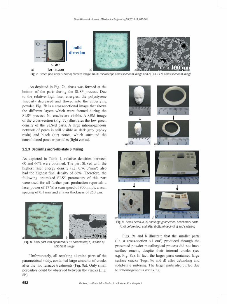
As depicted in Fig. 7a, dross was formed at the bottom of the parts during the SLS® process. Due to the relative high laser energies, the polystyrene viscosity decreased and flowed into the underlying powder. Fig. 7b is a cross-sectional image that shows the different layers which were formed during the SLS® process. No cracks are visible. A SEM image of the cross-section (Fig. 7c) illustrates the low green density of the SLSed parts. A large inhomogeneous network of pores is still visible as dark grey (epoxy resin) and black (air) zones, which surround the consolidated powder particles (light zones).
2.1.3 Debinding and Solid-state Sintering
As depicted in Table 1, relative densities between 60 and 66% were obtained. The part SLSed with the highest laser energy density (i.e. 0.76 J/mm³) also had the highest final density of 66%. Therefore, the following optimized SLS® parameters of this part were used for all further part production reported: a laser power of 17 W, a scan speed of 900 mm/s, a scan spacing of 0.1 mm and a layer thickness of 250 µm.
a) b) Fig. 8. Final part with optimized SLS® parameters; a) 3D and b)
BSE-SEM image
Unfortunately, all resulting alumina parts of the parametrical study, contained large amounts of cracks after the two furnace treatments (Fig. 8a). Only small porosities could be observed between the cracks (Fig. 8b).
a) b)
c) d) Fig. 9. Small demo (a, b) and large geometrical benchmark parts
(c, d) before (top) and after (bottom) debinding and sintering
Figs. 9a and b illustrate that the smaller parts (i.e. a cross-section <1 cm²) produced through the presented powder metallurgical process did not have surface cracks, despite their internal cracks (see e.g. Fig. 8a). In fact, the larger parts contained large surface cracks (Figs. 9c and d) after debinding and solid-state sintering. The larger parts also curled due to inhomogeneous shrinking.
a) b) c) Fig. 7. Green part after SLS®; a) camera image, b) 3D microscope cross-sectional image and c) BSE-SEM cross-sectional image

Strojniški vestnik - Journal of Mechanical Engineering 59(2013)11, 646-661
653Densification and Geometrical Assessments of Alumina Parts Produced Through Indirect Selective Laser Sintering of Alumina-Polystyrene Composite Powder
Fig. 10. Percentage linear shrinkage of outer and inner dimensions
2.2 Geometrical Assessments
Fig. 10 describes the percentage of linear shrinkage of different features of the benchmark parts (i.e. the parts depicted in Figs. 9c and d) as a function of the corresponding green dimension.
a)
b) Fig. 11. Directional dependency of shrinkage during debinding
and furnace sintering; a) percentage of linear shrinkage in x and y directions, b) percentage linear shrinkage in x/y and z direction as
a function of laser energy density
By examining the larger dimensions (>20 mm), it can be seen that the percentage of linear shrinkage was about 30%. The percentage of linear shrinkage seemed
to vary significantly for the smaller green dimensions. When comparing outer and inner dimensions, it can be observed that the outer dimensions shrunk more.
Fig. 11a describes the percentage of linear shrinkage of the benchmark parts in x ‘scan’ and y ‘cross-scan’ direction during debinding and SSS. Although the measured variation of % shrinkage was slightly larger for the y direction compared to the x direction, no large difference could be observed. In the rest of the paper, no distinction will be made between shrinkages in the x and y directions.
The cubic parts produced to study the SLS® parameters, were also used to investigate the percentage of shrinkage in the z direction. In Fig. 11b the percentage of linear shrinkages of the cubic parts are plotted as a function of the laser energy density. It can be observed that the shrinkage in the z direction was systematically larger than the shrinkage in the x/y direction.
As depicted in Table 2, the roughness in the x ‘scan’ direction is slightly lower than the roughness in the y ‘cross-scan’ direction. Furthermore, the final part is smoother than the green part.
Table 2. Mean roughness values of the benchmark part, depicted in Fig. 9d, after SLS® (green) and after SSS (final)
x direction y directionGreen part: Ra [µm] 18 22Green part: Rt [µm] 142 202Green part: Rz [µm] 107 152Final part: Ra [µm] 19 22Final part: Rt [µm] 128 167Final part: Rz [µm] 103 138
2.3 Densification Strategies
2.3.1 Warm Isostatic Pressing (WIP)
The WIP of the green parts resulted in an increase of the green density and of the geometrical shrinkage (not reported in Table 3). For part 2, the WIP increased the green density from 66 to 95% and resulted in a geometrical shrinkage of –10% (x/y direction) and –7% (z direction). Although part 3 was WIPed at a 10 °C higher temperature than part 2, the green density increased from 67 to 80% and the resulting geometrical shrinkage was only –3% (in all directions).
After debinding and solid-state sintering, the final densities of part 2 and 3 were 53 to 49%, respectively; the measured shrinkages were about 23% (in all directions): please see Table 3. This is lower than the density and shrinkage of the reference ‘part 1’ (see
Strojniški vestnik - Journal of Mechanical Engineering 59(2013)11, 646-661
654 Deckers, J. – Kruth, J.-P. – Cardon, L. – Shahzad, K. – Vleugels, J.
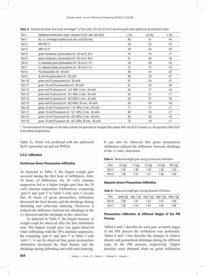
Table 3), which was produced with the optimized SLS® parameter set and not WIPed.
2.3.2 Infiltration
Continuous Green Pressureless Infiltration
As depicted in Table 4, the largest weight gain occurred during the first hour of infiltration. After 30 hours of infiltration, the 30 vol% alumina suspension led to a higher weight gain than the 20 vol% alumina suspension. Furthermore, comparing ‘part 4’ and ‘part 5’ in Table 3 with ‘part 1’ reveals that 30 hours of green pressureless infiltration decreased the final density and the shrinkage during debinding and solid-state sintering. Moreover, it reduced the difference between the shrinkage in the x/y direction and the shrinkage in the z direction.
As depicted in Table 5, the largest increase of weight could be observed after the first infiltration step. The highest weight gain was again observed when infiltrating with the 30% alumina suspension. By comparing ‘part 6’ and ‘part 7’ in Table 3 with ‘part 1’, it can be observed that green pressureless infiltration decreased the final density and the shrinkage during debinding and solid-state sintering.
It can also be observed that green pressureless infiltration reduced the difference between shrinkage in the x/y and z directions.
Table 4. Measured weight gain during continuous infiltration
Part 0 h [g] 1 h [g] 2 h [g] 3 h [g] 30 h [g]
Part 4 1.26 1.48 1.49 1.48 1.53
Part 5 1.28 1.57 1.57 1.58 1.63
Stepwise Green Pressureless Infiltration
Table 5. Measured weight gain during stepwise infiltration
Part green [g] step 1 [g] step 2 [g] step 3 [g] step 4 [g]
Part 6 1.28 1.47 1.54 1.57 1.59
Part 7 1.26 1.54 1.61 1.64 1.66
Pressureless Infiltration at Different Stages of the PM Process
Tables 6 and 7 describe for each part, at which stages of the PM process the infiltration was performed. Tables 6 and 7 also describe the changes in relative density and geometrical shrinkage during the different steps of the PM process, respectively. Higher densities were obtained when no green infiltration
Table 3. Sintered densities and linear shrinkages* of the cubic (10×10×10 mm³) alumina parts after additional densification steps
Part Additional densification steps (besides SLS®, deb. and SSS) ρ [%] x/y [%] z [%]
Part 1 No, i.e. shrinkage resulting from deb. and SSS only 66 -31 -44
Part 2 WIP100 °C 53 -22 -24
Part 3 WIP110 °C 49 -24 -23
Part 4 green continuous pressureless inf.: 20 vol.%, 30 h 54 -19 -17
Part 5 green continuous pressureless inf.: 30 vol.%, 30 h 51 -20 -18
Part 6 4 x stepwise green pressureless inf.: 20 vol.%, 4 h 48 -20 -18
Part 7 4 x stepwise green pressureless inf.: 30 vol.%, 4 h 47 -17 -15
Part 8 FS pressureless inf.: 30 vol% 66 -34 -32
Part 9 IS and FS pressureless inf.: 30 vol% 69 -33 -37
Part 10 green and FS pressureless inf.: 30 vol% 61 -24 -21
Part 11 green, IS and FS pressureless inf.: 30 vol% 61 -23 -20
Part 12 green and FS pressure inf.: 1.61 MPa; 5 min., 40 vol% 64 -17 -16
Part 13 green and FS pressure inf.: 16.1 MPa; 5 min., 40 vol% 63 -21 -17
Part 14 green and FS pressure inf.: 48.3 MPa; 5 min., 40 vol% 62 -21 -16
Part 15 green and FS pressure inf.: 48.3 MPa; 30 min., 40 vol% 63 -20 -18
Part 16 green, IS and FS pressure inf.: 1.61 MPa; 5 min., 40 vol% 71 -17 -17
Part 17 green, IS and FS pressure inf.: 16.1 MPa; 5 min., 40 vol% 85 -18 -17
Part 18 green, IS and FS pressure inf.: 48.3 MPa; 5 min., 40 vol% 84 -20 -16
Part 19 green, IS and FS pressure inf.: 48.3 MPa; 30 min., 40 vol% 76 -19 -17
* The dimensional shrinkages of this table indicate the geometrical changes that appear after the SLS® process (i.e. the geometry after SLS® is the reference geometry).

Strojniški vestnik - Journal of Mechanical Engineering 59(2013)11, 646-661
655Densification and Geometrical Assessments of Alumina Parts Produced Through Indirect Selective Laser Sintering of Alumina-Polystyrene Composite Powder
had been performed. In contrast, IS and FS infiltration increased the final densities of the parts. Furthermore, green infiltration decreased the part shrinkage. By comparing parts 8 to 11 with part 1 in Table 3, it can be observed that infiltration decreased the difference between shrinkages in the x/y direction and z direction.
Pressure Infiltration
Comparing parts 12 to 15 from Table 8 with part 10 of Table 6 reveals that when only applying green infiltration, the application of pressure did not significantly increase the final densities. Moreover, for both the pressure infiltrated and the pressureless infiltrated parts, the densities after the first SSS step were 52 to 55%. After FS infiltration and again full SSS, the densities were 61 to 64%. The shrinkages in the x/y and z directions after SSS were somewhat less when pressure infiltration was applied. For example, after the first full SSS step, x/y shrinkages of 18 to 21% (Table 9) instead of 24% (Table 7) were observed.
By comparing parts 16 to 19 from Table 8 with part 11 of Table 6, it can be seen that applying an extra IS pressure infiltration step had a more pronounced influence on the final densities: densities up to 82% were reached after the first full SSS step (compared to 58% for part 11 in Table 6). After FS infiltration and again SSS, densities up to 85% were assessed (compared to 61% for part 11 in Table 6). Applying the pressure for a longer time decreased the final densities: consider part 19 in Table 8. The shrinkages in the x/y and z directions after SSS were somewhat less when applying pressure infiltration instead of
pressureless infiltration: for example, after the first full SSS step, x/y shrinkages of -19 to -21% (Table 9) instead of -23% (Table 7) were obtained. The part shrinkages also decreased by applying an extra FS pressure infiltration step (Table 9). Finally, by comparing parts 12 to 19 with part 1 in Table 3, it can be once more observed that infiltration decreased the difference between the x/y shrinkage and the z shrinkage.
3 DISCUSSION
3.1 Production of Alumina Parts
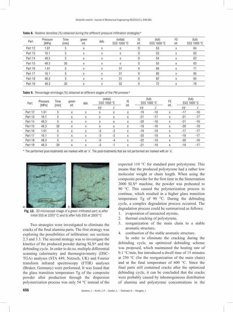
A disadvantage of the presented PM process is the occurrence of multiple cracks in the final parts when no post-densification step was applied (Fig. 8). Since the green SLSed parts did not contain cracks, they either originated during the debinding treatment or during solid-state sintering. In order to examine when exactly the cracks originated, two green (pressureless) infiltrated parts were further investigated. One part was debound and initially solid-state sintered at 1050 °C to give the brown part some strength without causing too much shrinkage. The other part was debound and solid-state sintered at 1600 °C. Both parts were cut with a diamond blade, and the cross-sections were visualized by the 3D microscope. It could be clearly observed that the IS part (Fig. 12a) had some big cracks. This means that the cracks originated during debinding. As shown in Fig. 12b, the cracks were still visible in the FS part after solid-state sintering at 1600 °C.
Table 6. Relative densities [%] obtained during the different pressureless infiltration strategies*
Partgreen inf.
deb.(initial)
SSS 1050 °C IS inf.
(full) SSS 1600 °C
FS inf.
(full) SSS 1600 °C
Part 8 o x o o 65 x 66Part 9 o x 38 x 72 x 69Part 10 x x o o 55 x 61Part 11 x x 31 x 58 x 61
Table 7. Percentage shrinkage [%] obtained at different stages of the PM process*
Partgreen inf.
deb.(initial) SSS 1050 °C IS
inf.(full) SSS 1600 °C FS
inf.(full) SSS 1600 °C
x/y z x/y z x/y zPart 8 o x o o o -32 -31 x -34 -32Part 9 o x -19 -24 x -32 -37 x -33 -37
Part 10 x x o o o -24 -23 x -24 -21Part 11 x x -8 -8 x -23 -22 x -23 -20
* The performed post-treatments are signed with an ‘x’. The post-treatments that are not performed are marked with an ‘o’.
Strojniški vestnik - Journal of Mechanical Engineering 59(2013)11, 646-661
656 Deckers, J. – Kruth, J.-P. – Cardon, L. – Shahzad, K. – Vleugels, J.
a) b) Fig. 12. 3D microscope image of a green infiltrated part; a) after
initial SSS at 1050°C; and b) after fully SSS at 1600°C
Two strategies were investigated to eliminate the cracks of the final alumina parts. The first strategy was exploring the possibilities of infiltration: see sections 2.3 and 3.3. The second strategy was to investigate the kinetics of the produced powder during SLS® and the debinding cycle. In order to do so, multiple differential scanning calorimetry and thermogravimetry (DSC-TGA) analyses (STA 449, Netzsch, UK) and Fourier transform infrared spectroscopy (FTIR) analyses (Bruker, Germany) were performed. It was found that the glass transition temperature Tg of the composite powder after production through the dispersion polymerization process was only 54 °C instead of the
expected 110 °C for standard pure polystyrene. This means that the produced polystyrene had a rather low molecular weight or chain length. When using the composite powder for the first time in the Sinterstation 2000 SLS® machine, the powder was preheated to 90 °C. This caused the polymerization process to continue, which resulted in a higher glass transition temperature Tg of 90 °C. During the debinding cycle, a complex degradation process occurred. The degradation process could be summarized as follows:1. evaporation of unreacted styrene,2. thermal cracking of polystyrene,3. reorganization of the main chain to a stable
aromatic structure,4. combustion of the stable aromatic structure.
In order to eliminate the cracking during the debinding cycle, an optimized debinding scheme was proposed, which maintained the heating rate of 0.1 °C/min, but introduced a dwell time of 15 minutes at 250 °C (for the reorganization of the main chain) and at the final temperature of 600 °C. Since the final parts still contained cracks after the optimized debinding cycle, it can be concluded that the cracks were probably caused by inhomogeneous distribution of alumina and polystyrene concentrations in the
Table 8. Relative densities [%] obtained during the different pressure infiltration strategies*
PartPressure
[MPa]Time [min]
green inf.
deb.(initial)
SSS 1050 °C IS inf.
(full) SSS 1600 °C
FS inf.
(full) SSS 1600 °C
Part 12 1.61 5 x x o O 53 x 64
Part 13 16.1 5 x x o O 52 x 63
Part 14 48.3 5 x x o O 54 x 62
Part 15 48.3 30 x x o O 55 x 63
Part 16 1.61 5 x x 31 X 66 x 71
Part 17 16.1 5 x x 31 X 80 x 85
Part 18 48.3 5 x x 31 X 82 x 84
Part 19 48.3 30 x x 32 X 72 x 76
Table 9. Percentage shrinkage [%] obtained at different stages of the PM process*
PartPressure
[MPa]Time [min]
green inf.
deb.(initial)
SSS 1050 °C IS inf.
(full) SSS 1600 °C FS
inf.
(full) SSS 1600 °C
x/y z x/y z x/y zPart 12 1.61 5 x x o o o -19 -16 x -17 -16Part 13 16.1 5 x x o o o -21 -17 x -21 -17Part 14 48.3 5 x x o o o -20 -16 x -21 -16Part 15 48.3 30 x x o o o -18 -16 x -20 -18Part 16 1.61 5 x x -2 -2 x -19 -19 x -17 -17Part 17 16.1 5 x x -3 -2 x -20 -18 x -18 -17Part 18 48.3 5 x x -5 -4 x -22 -18 x -20 -16Part 19 48.3 30 x x -3 -1 x -21 -18 x -19 -17
* The performed post-treatments are marked with an ‘x’. The post-treatments that are not performed are marked with an ‘o’.

Strojniški vestnik - Journal of Mechanical Engineering 59(2013)11, 646-661
657Densification and Geometrical Assessments of Alumina Parts Produced Through Indirect Selective Laser Sintering of Alumina-Polystyrene Composite Powder
composite starting powder. The inhomogeneous concentrations of alumina and polystyrene led to inhomogeneous shrinkage and the resulting cracks in the debinding step.
Future research may focus on exploring further the influence of atmosphere conditions on the kinetic behaviour of the produced polystyrene during the debinding. Other powder production routes can also be explored to produce more homogeneous and spherical composite alumina-polystyrene starting powder, e.g. a dissolution-reprecipitation route (Shahzad et al. [38]).
3.2 Geometrical Assessments
The benchmark parts depicted in Figs. 9c and d were used to investigate the percentage of shrinkage during debinding and SSS. The measured shrinkages were caused by:• (mostly) attractive capillary forces during
debinding (Rahaman [39]; Megias-Alguacil and Gauckler [40]),
• attractive Van der Waals forces after debinding and before solid-state sintering,
• shrinkage due to atomic diffusion during SSS,• cracks and curling due to inhomogeneous
shrinking in the debinding and/or SSS step.Cracks did not contribute to the shrinking process.
This means that if no cracks had occurred during the debinding cycle, a linear shrinkage larger than 30% would have been observed.
a) b) Fig. 13. Attractive forces during shrinkage of a) an outer and b)
inner geometry
The large variety of the shrinkage for smaller green dimensions (Fig. 10) was probably due to measurement errors, which were relatively larger for smaller dimensions. A possible explanation for the observation that outer dimensions shrunk more than inner dimensions can be found by examining the attractive forces that occurred during shrinkage. As illustrated in Fig. 13a, the attractive forces were not constrained and tended to reduce the outer contours. In this case, the reduction of the outer contours and the shrinkage of the debound part acted in the same
direction. In contrast, the attractive forces tended to increase internal contours (Fig. 13b). The shrinkage of the debound part counteracted this increase, resulting in a lower total shrinkage of the internal geometry.
3.3 Densification Strategies
3.3.1 Warm Isostatic Pressing (WIP)
The different densities of part 2 and part 3 after the WIP process might be related to aging of the composite material of the SLSed sample. Although no cracks could be observed after WIP (Fig. 14a), one large internal crack could be observed in the cross-sections of the parts after debinding and solid-state sintering (Fig. 14c). This was in contrast with the large amount of smaller cracks in part 1 (Fig. 8a), which was not WIPed. The large crack might be related to the lower densities and lower shrinkages of the WIPed samples after SSS (see Table 3). Besides the difference in amount and size of cracks, the green and final microstructure of a WIPed part (Figs. 14b and d) was similar to that of a part which was not WIPed (Figs. 7c and 8b).
3.3.2 Infiltration
Unfortunately, all the infiltrated parts contained big internal cracks and voids (see e.g. Fig. 15a) after the solid-state sintering process. This was in contrast with the large amount of small cracks, which occurred when no infiltration was applied (see Fig. 8a). As illustrated by Fig. 15b, only small porosities were obtained between the cracked zones. A dense alumina shell was also observed at the edges of the parts (Fig. 15c). This shell was probably created when the alumina suspension was entering the pores and obstructed further infiltration. The shell formation might explain different shrinkage results as:• The decrease of part shrinkage when green
(pressureless) infiltration was applied. In this case, the dense shell enlarged the part and prohibited the part to shrink freely.
• The decrease of part shrinkage when pressure infiltration instead of pressureless infiltration was applied. In this case, the pressure caused the formation of a thicker shell.
• Possibly, shell formation also decreased the difference between shrinkages in the x/y direction and z directions.

Strojniški vestnik - Journal of Mechanical Engineering 59(2013)11, 646-661
658 Deckers, J. – Kruth, J.-P. – Cardon, L. – Shahzad, K. – Vleugels, J.
a) b)
c) d) Fig. 14. 3D microscope images (a, c), BSE-SEM image (b) and
SE-SEM images (d) of a part after WIP (a, b) and part 3 after WIP, debinding and SSS (c, d)
A drawback of the application of the pressure infiltration method was the breaking of the parts. This might be caused by air that was trapped in the part and squeezed during the infiltration process.
However, the cracks could be filled with alumina, and densities up to 85% were obtained. Fig. 16a shows a 3D microscope image of part 18, which had a density of 84%. A large crack, pressure infiltrated with alumina, is clearly visible. Upon closer examination of the large infiltrated crack, micro-cracks surrounded by dense alumina become visible (Fig. 16b). Smaller micro-cracks, surrounded by dense alumina are also visible in the bulk material, i.e. in the infiltrated zones next to the large crack (Fig. 16c).
4 SUMMARY AND CONCLUSIONS
A PM process was presented to produce freeform alumina parts with a relative density of 66% through indirect SLS®. The PM process comprised a dispersion polymerization process to produce composite powder particles, as well as a tuned SLS® process, a debinding, and a solid-state sintering sintering step. It was found that the final parts produced through this PM process contained cracks, which were formed during debinding. The larger parts (i.e. a cross-section >1 cm²), contained cracks that were also visible at the
a) b) c) Fig. 15. a) 3D microscope image of part 11, b) BSE-SEM micrograph taken in a non-cracked area of part 8 and c) SE-SEM micrograph taken
at the edge of part 9
a) b) c) Fig. 16. a) 3D microscope image of part 18, showing a crack pressure infiltrated with alumina; b) and c) the infiltrated crack and the zone
around the infiltrated crack are detailed in BSE-SEM images

Strojniški vestnik - Journal of Mechanical Engineering 59(2013)11, 646-661
659Densification and Geometrical Assessments of Alumina Parts Produced Through Indirect Selective Laser Sintering of Alumina-Polystyrene Composite Powder
surface. Furthermore, the larger parts tended to curl during the debinding and SSS step. The cracks and the curling were probably caused by inhomogeneous distribution of alumina and polystyrene concentrations in the composite starting powder.
Through geometrical assessments, the percentage shrinkage that occurred during the debinding and SSS process was investigated. The measured shrinkages were caused by capillary forces, Van der Waals forces, atomic diffusion, cracking and curling of the parts. The shrinkage was more or less the same in the scan and cross-scan directions (about –31%) but much larger in the building direction (about –44%). Furthermore, the unconstrained attractive shrinking forces seemed to let outer dimensions shrink more compared to inner dimensions.
Densification strategies were presented to improve the density of the fabricated parts and reduce the occurrence of cracks in the final parts: WIP and infiltration. Although WIP could increase green densities from 66 to 95%, the final density and shrinkage during debinding and solid-state sintering was lower when WIP was used. This might be due to the presence of large cracks in the final parts.
Pressureless and pressure infiltration tests with alumina-ethanol suspensions were performed. After pressureless infiltration, large cracks could be observed in the final parts. During continuous green pressureless infiltration, the largest weight gain was obtained during the first hour using a 30 vol% alumina suspension. During stepwise green pressureless infiltration, the largest weight gain was observed after the first step using a 30 vol% alumina suspension. Furthermore, green pressureless infiltration decreased the part shrinkage during debinding and solid-state sintering. The combined influence of green and/or IS and FS pressureless infiltration with a 30 vol% alumina suspension was also examined. As a result, higher densities were observed when no green pressureless infiltration was performed. In contrast, IS and FS pressureless infiltration increased the final densities of the parts. In general, pressureless infiltration reduced the difference between the shrinkage in the x/y direction and the shrinkage in the z direction. The influence of pressureless infiltration on the geometrical shrinkage might be related to the formation of a dense shell at the edges of the part.
Finally, the combined influence of green and FS pressure infiltration with or without IS pressure infiltration was investigated, using 40 vol% alumina suspensions. As with pressureless infiltration, shell formation might be related to the reduction of geometrical shrinkage during the PM process and the
reduced difference between the shrinkage in the x/y and z directions, respectively. Without IS pressure infiltration, the densities of the final parts were similar to the densities obtained by pressureless infiltration. The application of IS pressure infiltration led to an increase of the part densities up to 84%, since the cracks that occurred during the debinding process could be filled with alumina. Nevertheless, micro-cracks arose. The micro-cracks probably occurred due to non-homogeneous shrinkage during solid-state sintering.
5 ACKNOWLEDGEMENTS
This work was financially supported by the Flemish Institute for the Promotion of Scientific Techno-logical Research in Industry (IWT) under project SBO-DiRaMaP.
6 REFERENCES
[1] Cormier, D., Taylor, J., Unnanon, K., Kulkarni, P., West, H. (2000). Experiments in Layered Electro-Photographic Printing. Proceedings of the SFF Symposium, p. 267-274.
[2] Khoshnevis, B., Asiabanpour, B., Mojdeh, M., Koraishy, B., Palmer, K., Deng, Z. (2003). SIS-A new SFF method based on powder sintering. Rapid Prototyping Journal, vol. 9, no. 1, p. 30-36, DOI:10.1108/13552540310455638.
[3] Brooks, H., Aitchison, D. (2010). A review of state-of-the-art large-size foam cutting rapid prototyping and manufacturing technologies. Rapid Prototyping Journal, vol. 16, no. 5, p. 318-327, DOI:10.1108/13552541011065713.
[4] de Smit, B., Broeck, H.J. (2004). Analysing the cutting process of a heated flexible blade in extruded polystyrene foam. Proceeding of the SFF Symposium, p. 591-601.
[5] Mahale, T.R., Taylor, J.B., Cormier, D.R. (2000). Five-axis freeform fabrication of the thermoplastic parts via SWIFT. Proceedings of the SFF Symposium, p. 289-297.
[6] Cheah, C.M., Chua, C.K., Lee, C.W., Feng, C., Totong, K. (2005). Rapid prototyping and tooling techniques: a review of applications for rapid investment casting. The International Journal of Advanced Manufacturing Technology, vol. 25, no. 3-4, p. 308-320, DOI:10.1007/s00170-003-1840-6.
[7] Kinsella, M.E., Lilly, B., Carpenter, B., Cooper, K. (2004). Ejection forces and friction coefficients from injection molding experiments using rapid tooled inserts. Proceedings of the SFF Sympsium, p. 669-680.
[8] Kruth, J.P., Levy, G., Schindel, R., Craeghs, T., Yasa, E. (2008). Consolidation of polymer powders by selective laser sintering. Proceedings of the 3rd International

Strojniški vestnik - Journal of Mechanical Engineering 59(2013)11, 646-661
660 Deckers, J. – Kruth, J.-P. – Cardon, L. – Shahzad, K. – Vleugels, J.
Conference on Polymers and Moulds Innovations, p. 15-30.
[9] Levy, G.N., Schindel, R., Kruth, J.P. (2003). Rapid Manufacturing and Rapid Tooling with layer manufacturing (LM) technologies, state of the art and future perspectives. Annals of the CIRP, vol. 52, no. 2, p. 589-609, DOI:10.1016/S0007-8506(07)60206-6.
[10] Yang, J., Shi, Y., Shen, Q., Yan, C. (2009). Selective laser sintering of HIPS and investment casting technology. Journal of Materials Processing Technology, vol. 209, no 4, p. 1901-1908, DOI:10.1016/j.jmatprotec.2008.04.056.
[11] Ku, C.W., Gibson, I., Cheung, W.L. (2002). Selective Laser Sintered CastForm Polystyrene with controlled porosity and its infiltration characteristics by red wax. Proceedings of the SFF Symposium, p. 107-114.
[12] Liu, H.J., Li, Y.M., Hao, Y., Dong, X.P., Huang, N.Y. (2005). Study of rapid casting process based on SLS®
prototypes. Advances in Abrasive Technology VIII, vol. 291-292, p. 593-596.
[13] Niino, T., Yamada, H. (2004). Full densification of SLS® parts by re-melting. Proceedings of the SFF Symposium, p. 400-407.
[14] Hongjun, L., Zitian, F., Naiyu, H., Xuanpu, D. (2003). A note on rapid manufacturing process of metallic parts based on SLS® plastic prototype. Journal of Meterials Processing Technology, vol. 142, no 3, p. 710-713, DOI:10.1016/S0924-0136(03)00811-2.
[15] Cevolinni, F., Davis, S., Rinland, S. (2008). New rapid casting techniques for competitive motor sports. Proceedings of the SFF Symposium, p. 558-569.
[16] Pfeifer, R., Wang, L., Eyerer, P. (1999). Rapid Tooling of ceramic parts and molds using high pressure slip casting of Si3N4. Proceedings of the SFF Symposium, p. 615-622.
[17] Kruth, J.P., Levy, G., Klocke, F., Childs T.H.C. (2007). Consolidation phenomena in laser and powder-bed based layered manufacturing. CIRP Annals – Manufacturing Technology, vol. 56, no. 2, p. 730-759, DOI:10.1016/j.cirp.2007.10.004.
[18] Dewidar, M.M., Lim, J.-K., Dalgarno, K.W. (2008). A comparison between direct and indirect selective laser sintering of metals. Journal of Materials Science Technology, vol. 24, no. 2, p. 227-232.
[19] Tang, H.-H., Chiu, M.-L., Yen, C.Y. (2011). Slurry-based selective laser sintering of polymer-coated ceramic powders to fabricate high strength alumina parts. Journal of the European Ceramic Society, vol. 31, no. 8, p. 1383-1388, DOI:10.1016/j.jeurceramsoc.2011.02.020.
[20] Lee, I. (1998). Rapid full densification of alumina-glass composites fabricated by a Selective Laser Sintering process. Journal of Materials Science Letters, vol. 17, no. 22, p. 1907-1911, DOI:10.1023/A:1006600208059.
[21] Lee, I. (2002). Influence of heat treatment upon SLS® processed composites fabricated with alumina and monoclinic HBO2. Journal of Materials
Science Letters, vol. 21, no. 3, p. 209-212, DOI:10.1023/A:1014756724160.
[22] Liu, Z.H., Nolte, J.J., Packard, J.I., Hilmas, G., Dogan, F. Leu, M.C. (2007). SLS® of high density alumina ceramic parts. Proceedings of 35th International MATADOR Conference, p. 351-354, DOI:10.1007/978-1-84628-988-0_79.
[23] Leu, M., Pattnaik, S. Hilmas, G.E. (2012). Investigation of Laser Sintering for freeform fabrication of zirconium diboride parts. Journal of Virtual and Physical Prototyping, vol. 7, no. 7, p. 25-36, DOI:10.1080/17452759.2012.666119.
[24] Liu, J., Zhang, B., Yan, C. Shi, Y. (2010). The effect of processing parameters on characteristics of Selective Laser Sintering dental glass-ceramic powder. Rapid Prototyping Journal, vol. 16, no. 2, p. 138-145, DOI:10.1108/13552541011025861.
[25] Evans, R.S. (2005). Indirect Rapid Manufacturing of Silicon Carbide Composites. PhD thesis, The University of Texas, Austin.
[26] Stevinson, B., Bourell, D.L. Beaman, J.J. (2006). Dimensional Stability During Post-Processing of Selective Laser Sintered Ceramic Preforms. Virtual and Rapid Prototyping, vol. 1, no. 4, p. 209-216, DOI:10.1080/17452750601107003.
[27] Agarwala, M., Klosterman, D., Osborne, N., Lightman, A. (1999) Hard metal tooling via SFF of ceramics and powder metallurgy. Proceedings of the SFF Symposium, p. 759-766.
[28] Subramanian, K., Vail, N., Barlow, J., Marcus, H. (1995). Selective laser sintering of alumina with polymer binders. Rapid Prototyping Journal, vol. 1, no. 2, p. 24-35, DOI:10.1108/13552549510086844.
[29] Goodridge, R.D., Wood, D.J., Ohtsuki, C. Dalgarno, K.W. (2007). Biological evaluation of an apatite-mullite glass-ceramic produced via Selective Laser Sintering. Acta Biomaterialia, vol. 3, no. 2, p. 221-231, DOI:10.1016/j.actbio.2006.10.005.
[30] Chakravarthy, K.M., Bourell, D.L. (2010). Binder development for indirect SLS of non metallics. Proceedings of the SFF Symposium, p. 81-90.
[31] Bai, P., Cheng, J., Liu, B. (2005) Selective Laser Sintering of polymer-coated Al2O3/ZrO2/TiC ceramic powder. Transactions of Nonferrous Metals Society of China, vol. 15, no. 2, p. 261-265.
[32] Zheng, H., Zhang, J., Lu, S., Wang, G., Xy, Z. (2006). Effect of core-shell composite particles on the sintering behavior and properties of nano-Al2O3/polystyrene composite prepared by SLS®. Materials Letters, vol. 60, no. 9-10, p. 1219-1223, DOI:10.1016/j.matlet.2005.11.003.
[33] Deckers, J., Shahzad, K., Vleugels, J., Kruth, J.P. (2012). Isostatic pressing assisted indirect selective laser sintering of alumina components. Rapid Prototyping Journal, vol. 18, no. 5, p. 409-419, DOI:10.1108/13552541211250409.
[34] Yang, H.C., Lee, J.W., Kim, K.T. (2004). Ruber isostatic pressing of metal powder under warm

Strojniški vestnik - Journal of Mechanical Engineering 59(2013)11, 646-661
661Densification and Geometrical Assessments of Alumina Parts Produced Through Indirect Selective Laser Sintering of Alumina-Polystyrene Composite Powder
temperatures. Powder Technology, vol. 134, no. 3, p. 249-251, DOI:10.1016/j.powtec.2003.01.001.
[35] Galusek, D., Sedlacek, J., Riedel, R. (2007). Al2O3-SiC composites prepared by warm pressing and sintering of an organosilicon polymer coated alumina-powder. Journal of the European Ceramic Society, vol. 27, p. 2385-2392, DOI:10.1016/j.jeurceramsoc.2006.09.007.
[36] Deckers, J., Kruth, J.P., Shahzad, K., Vleugels, J. (2012). Density improvement of alumina parts produced through Selective Laser Sintering of alumina-polyamide composite powder. CIRP Annals – Manufacturing Technology, vol. 61, no. 1, p. 211-214, DOI:10.1016/j.cirp.2012.03.032.
[37] Cardon, L., Deckers, J., Verberckmoes, A., Ragaert, K., Delva, L., Shahzad, K., Vleugels, J., Kruth J.P. (2012). Polystyrene coated alumina powder via dispersion polymerization for indirect selective laser sintering
applications. Journal of Applied Polymer Science, vol. 128, no. 3, p. 2121-2128, DOI:10.1002/app.38388.
[38] Shahzad, K., Deckers, J., Boury, S., Neirinck, B., Kruth, J., Vleugels, J. (2012). Preparation and indirect selective laser sintering of alumina/PA microspheres. Ceramics International, vol. 38, no. 2, p. 1241-1247, DOI:10.1016/j.ceramint.2011.08.055.
[39] Rahaman, M.N. (2003). Chapter 6: Powder consolidation and forming of ceramics. Ceramic Processing and Sintering – 2nd edition, Marcel Dekker Inc., New York.
[40] Megias-Alguacil D., Gauckler L.J. (2010). Capillary and van der Waals forces between uncharged colloidal particles linked by a liquid bridge. Colloid and Polymer Science, vol. 288, p. 133-139, DOI:10.1007/s00396-009-2106-0.