dental air system
TRANSCRIPT
Installation and Operation Manual
DENTAL AIR SYSTEM
Air Techniques, Inc.Page 2
AS10NEO, AS21NEO, AS22NEO, AS30NEO, AS40NEO, AS50NEO & AS70NEO
TABLE OF CONTENTSSection PageSafety Instructions . . . . . . . . . . . . . . . . . . . . . . . . . . . . . . . . . . . . . . . . . . . . . . . . . . . . . 2Congratulations . . . . . . . . . . . . . . . . . . . . . . . . . . . . . . . . . . . . . . . . . . . . . . . . . . . . . . 3Purpose of this Manual . . . . . . . . . . . . . . . . . . . . . . . . . . . . . . . . . . . . . . . . . . . . . . . . . 3Sizing Guide . . . . . . . . . . . . . . . . . . . . . . . . . . . . . . . . . . . . . . . . . . . . . . . . . . . . . . . . 3Key Parts Identification . . . . . . . . . . . . . . . . . . . . . . . . . . . . . . . . . . . . . . . . . . . . . . . . . 4Supplied Components . . . . . . . . . . . . . . . . . . . . . . . . . . . . . . . . . . . . . . . . . . . . . . . . . 5Site Requirements . . . . . . . . . . . . . . . . . . . . . . . . . . . . . . . . . . . . . . . . . . . . . . . . . . . . . 6Installation Information . . . . . . . . . . . . . . . . . . . . . . . . . . . . . . . . . . . . . . . . . . . . . . . . . 8Tandem Compressor Setup . . . . . . . . . . . . . . . . . . . . . . . . . . . . . . . . . . . . . . . . . . . . 10Touch Screen Controls . . . . . . . . . . . . . . . . . . . . . . . . . . . . . . . . . . . . . . . . . . . . . . . . 12Operating Information . . . . . . . . . . . . . . . . . . . . . . . . . . . . . . . . . . . . . . . . . . . . . . . . 17Troubleshooting . . . . . . . . . . . . . . . . . . . . . . . . . . . . . . . . . . . . . . . . . . . . . . . . . . . . . 18Maintenance . . . . . . . . . . . . . . . . . . . . . . . . . . . . . . . . . . . . . . . . . . . . . . . . . . . . . . . 20Replacement Parts . . . . . . . . . . . . . . . . . . . . . . . . . . . . . . . . . . . . . . . . . . . . . . . . . . . 22Optional Accessories . . . . . . . . . . . . . . . . . . . . . . . . . . . . . . . . . . . . . . . . . . . . . . . . . 23
Product Specifications . . . . . . . . . . . . . . . . . . . . . . . . . . . . . . . . . . . . . . . . . . . . . . . . . 24Warranty . . . . . . . . . . . . . . . . . . . . . . . . . . . . . . . . . . . . . . . . . . . . . . . . . . . . . . . . . . 25On-Line Warranty Registration . . . . . . . . . . . . . . . . . . . . . . . . . . . . . . . . . . . . . . . . . . . 25
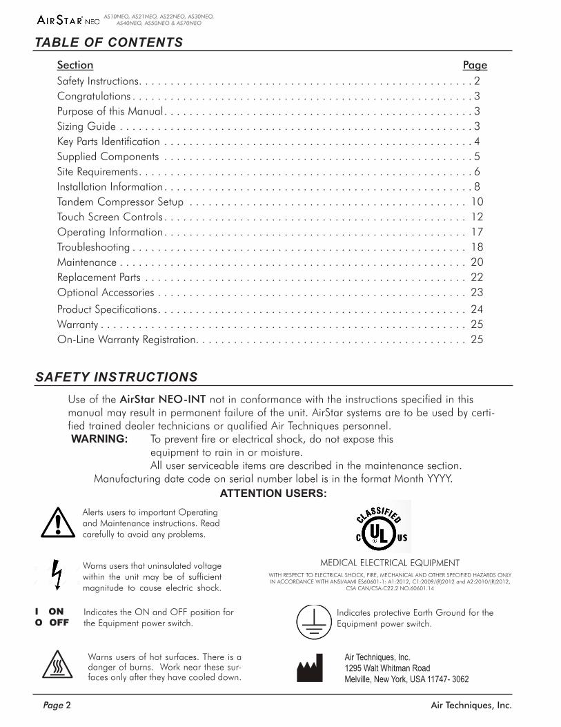
Use of the AirStar NEO-INT not in conformance with the instructions specified in this manual may result in permanent failure of the unit . AirStar systems are to be used by certi-fied trained dealer technicians or qualified Air Techniques personnel .WARNING: To prevent fire or electrical shock, do not expose this
equipment to rain in or moisture . All user serviceable items are described in the maintenance section .
Manufacturing date code on serial number label is in the format Month YYYY .ATTENTION USERS:
SAFETY INSTRUCTIONS
Alerts users to important Operating and Maintenance instructions . Read carefully to avoid any problems .
Warns users that uninsulated voltage within the unit may be of sufficient magnitude to cause electric shock .
Indicates the ON and OFF position for the Equipment power switch .
I ONO OFF
Indicates protective Earth Ground for the Equipment power switch .
Air Techniques, Inc. 1295 Walt Whitman RoadMelville, New York, USA 11747- 3062
Warns users of hot surfaces . There is a danger of burns . Work near these sur-faces only after they have cooled down .
MEDICAL ELECTRICAL EQUIPMENTWITH RESPECT TO ELECTRICAL SHOCK, FIRE, MECHANICAL AND OTHER SPECIFIED HAZARDS ONLY IN ACCORDANCE WITH ANSI/AAMI ES60601-1: A1:2012, C1:2009/(R)2012 and A2:2010/(R)2012,
CSA CAN/CSA-C22 .2 NO .60601 .14
Page 3Air Techniques, Inc.
AS10NEO, AS21NEO, AS22NEO, AS30NEO, AS40NEO, AS50NEO & AS70NEO
CONGRATULATIONSThe AirStar NEO series combines Air Techniques’ exclusive Membrane Dryer technology and new integrated diagnostic monitoring functions for a state-of-the-art dental air compressor . Air is quadruple filtered by the Membrane Dryer to ensure it is the cleanest and driest possible . The intelligent controls features a full color, digital Touch Screen Display, providing trouble-free performance by allowing easy accessibility to user settings and setup controls . The system continuously monitors itself and delivers diagnostic controls keeping you informed of preventive maintenance with "smart alarms" .Your AirStar NEO generates 100% oil-less, ultra-dry dental air which protects valuable handpieces from premature failure due to the effects of moist air and the build-up of oil residue . Because no oil is used for mechanical lubrication, there is no chance of introducing an oily film to a prepared surface which could compromise resin retention and restorations, wasting chair time . Most important, your patient's health is protected with ultra-dry air that provides an environment that is not conducive to bacterial growth .The AirStar NEO utilizes a long stroke, small bore piston to compress the air . This piston is bonded with an anti-friction polymer to eliminate the need for oil . The air is forced through the Membrane Dryer system consisting of the cooler and the membrane . This system removes moisture and air impurities providing the driest possible compressed air while maximizing performance . This 100% ultra-dry air is reserved in the main storage tank for use by the operatory air system .
The AirStar NEO features include: Low pressure dew point Compact size for space-saving installation
Virtually Maintenance Free Maximum dryness with quadruple filtered air
Uninterrupted compressor availability Intelligent controls for trouble-free performance
Since 1971, when Air Techniques pioneered the manufacture of oil-less air for dentistry, thousands of dentists have depended on their AirStar . Now that your practice has an AirStar NEO, you, too, can depend on the delivery of 100% oil-less, ultra-dry air and efficient, trouble-free operation .
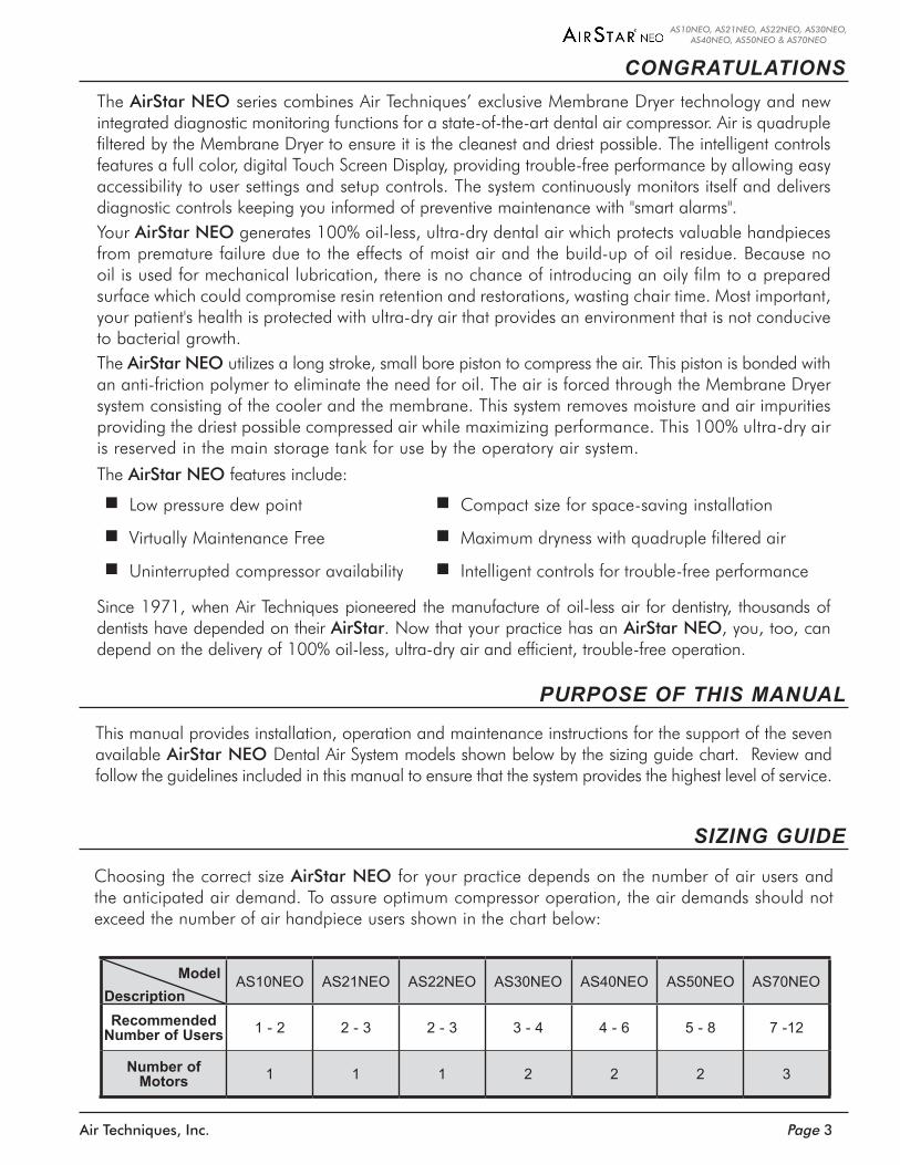
Choosing the correct size AirStar NEO for your practice depends on the number of air users and the anticipated air demand . To assure optimum compressor operation, the air demands should not exceed the number of air handpiece users shown in the chart below:
SIZING GUIDE
AS10NEO AS21NEO AS22NEO AS30NEO AS40NEO AS50NEO AS70NEO
Recommended Number of Users 1 - 2 2 - 3 2 - 3 3 - 4 4 - 6 5 - 8 7 -12
Number of Motors 1 1 1 2 2 2 3
ModelDescription
PURPOSE OF THIS MANUAL
This manual provides installation, operation and maintenance instructions for the support of the seven available AirStar NEO Dental Air System models shown below by the sizing guide chart . Review and follow the guidelines included in this manual to ensure that the system provides the highest level of service .
Air Techniques, Inc.Page 4
AS10NEO, AS21NEO, AS22NEO, AS30NEO, AS40NEO, AS50NEO & AS70NEO
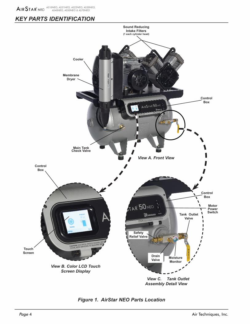
KEY PARTS IDENTIFICATION
Figure 1. AirStar NEO Parts Location
Main Tank Check Valve
Cooler
Sound Reducing Intake Filters
(1 each cylinder head)
MembraneDryer
View A. Front View
ControlBox
Main Tank Check Valve
View C. Tank Outlet Assembly Detail View
Drain Valve
Tank Outlet Valve
Moisture Monitor
Safety Relief Valve
Motor Power Switch
ControlBox
View B. Color LCD Touch Screen Display
ControlBox
Touch Screen
Page 5Air Techniques, Inc.
AS10NEO, AS21NEO, AS22NEO, AS30NEO, AS40NEO, AS50NEO & AS70NEO
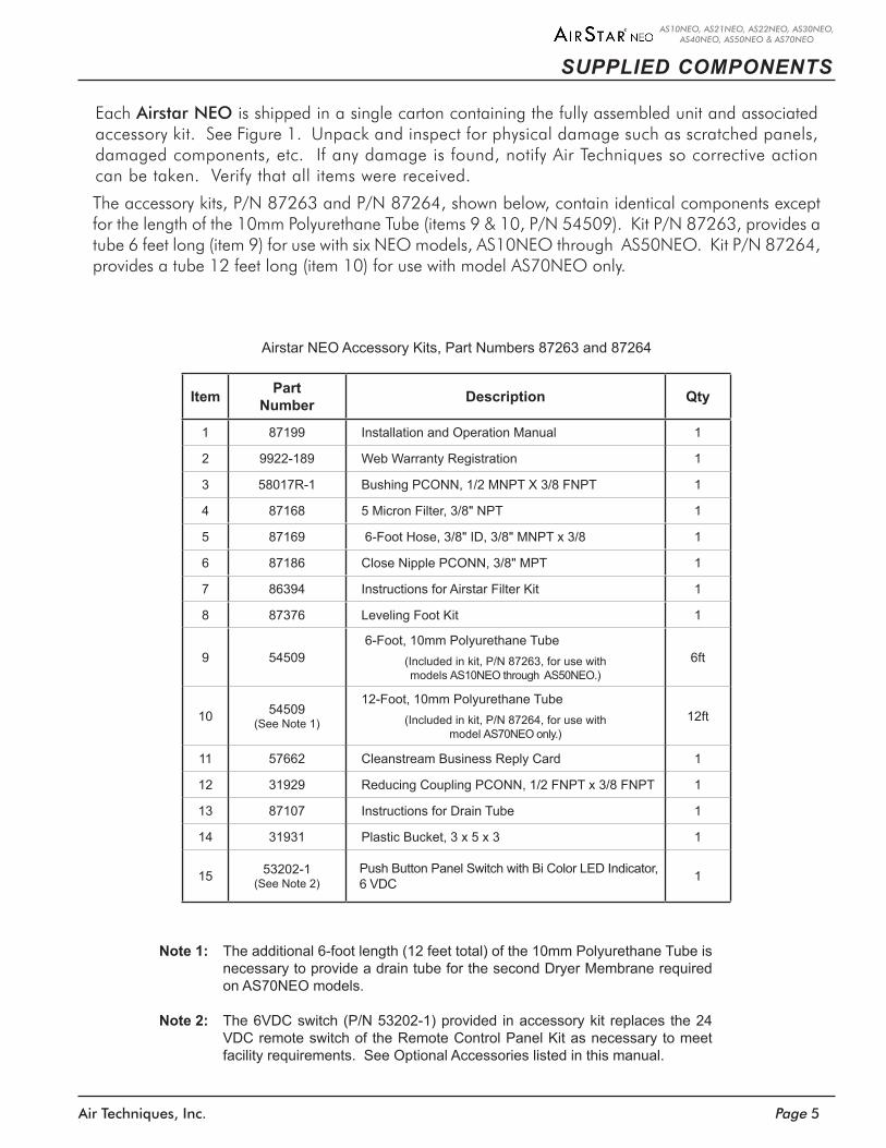
Airstar NEO Accessory Kits, Part Numbers 87263 and 87264
Item PartNumber Description Qty
1 87199 Installation and Operation Manual 1
2 9922-189 Web Warranty Registration 1
3 58017R-1 Bushing PCONN, 1/2 MNPT X 3/8 FNPT 1
4 87168 5 Micron Filter, 3/8" NPT 1
5 87169 6-Foot Hose, 3/8" ID, 3/8" MNPT x 3/8 1
6 87186 Close Nipple PCONN, 3/8" MPT 1
7 86394 Instructions for Airstar Filter Kit 1
8 87376 Leveling Foot Kit 1
9 54509 6-Foot, 10mm Polyurethane Tube
(Included in kit, P/N 87263, for use with models AS10NEO through AS50NEO.)
6ft
10 54509(See Note 1)
12-Foot, 10mm Polyurethane Tube(Included in kit, P/N 87264, for use with
model AS70NEO only.)12ft
11 57662 Cleanstream Business Reply Card 1
12 31929 Reducing Coupling PCONN, 1/2 FNPT x 3/8 FNPT 1
13 87107 Instructions for Drain Tube 1
14 31931 Plastic Bucket, 3 x 5 x 3 1
15 53202-1(See Note 2)
Push Button Panel Switch with Bi Color LED Indicator, 6 VDC 1
Note 1: The additional 6-foot length (12 feet total) of the 10mm Polyurethane Tube is necessary to provide a drain tube for the second Dryer Membrane required on AS70NEO models.
Note 2: The 6VDC switch (P/N 53202-1) provided in accessory kit replaces the 24 VDC remote switch of the Remote Control Panel Kit as necessary to meet facility requirements. See Optional Accessories listed in this manual.
SUPPLIED COMPONENTS
Each Airstar NEO is shipped in a single carton containing the fully assembled unit and associated accessory kit . See Figure 1 . Unpack and inspect for physical damage such as scratched panels, damaged components, etc . If any damage is found, notify Air Techniques so corrective action can be taken . Verify that all items were received .
The accessory kits, P/N 87263 and P/N 87264, shown below, contain identical components except for the length of the 10mm Polyurethane Tube (items 9 & 10, P/N 54509) . Kit P/N 87263, provides a tube 6 feet long (item 9) for use with six NEO models, AS10NEO through AS50NEO . Kit P/N 87264, provides a tube 12 feet long (item 10) for use with model AS70NEO only .
Air Techniques, Inc.Page 6
AS10NEO, AS21NEO, AS22NEO, AS30NEO, AS40NEO, AS50NEO & AS70NEO
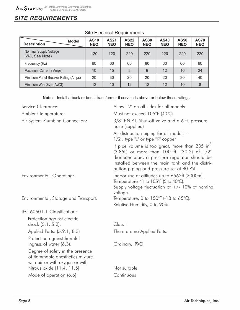
Note: Install a buck or boost transformer if service is above or below these ratings
Service Clearance: Allow 12" on all sides for all models .
Ambient Temperature: Must not exceed 105°F (40°C)
Air System Plumbing Connection: 3/8" F .N .P .T . Shut-off valve and a 6 ft . pressure hose (supplied)
Air distribution piping for all models - 1/2", type "L" or type "K" copper
If pipe volume is too great, more than 235 in3 (3 .85L) or more than 100 ft . (30 .2) of 1/2" diameter pipe, a pressure regulator should be installed between the main tank and the distri-bution piping and pressure set at 80 PSI .
Environmental, Operating: Indoor use at altitudes up to 6562ft (2000m) . Temperature 41 to 105°F (5 to 40°C) .
Supply voltage fluctuation of +/- 10% of nominal voltage .
Environmental, Storage and Transport: Temperature, 0 to 150°F (-18 to 65°C) . Relative Humidity, 0 to 90% .
IEC 60601-1 Classification:
Protection against electric shock (5 .1, 5 .2) . Class I
Applied Parts: (5 .9 .1, 8 .3) There are no Applied Parts .
Protection against harmful ingress of water (6 .3) . Ordinary, IPXO
Degree of safety in the presence of flammable anesthetics mixture with air or with oxygen or with nitrous oxide (11 .4, 11 .5) . Not suitable .
Mode of operation (6 .6) . Continuous
SITE REQUIREMENTS
Site Electrical RequirementsAS10 NEO
AS21 NEO
AS22 NEO
AS30 NEO
AS40 NEO
AS50 NEO
AS70 NEO
Nominal Supply Voltage (VAC, See Note) 120 120 220 220 220 220 220
Frequency (Hz) 60 60 60 60 60 60 60
Maximum Current ( Amps) 10 15 8 9 12 16 24
Minimum Panel Breaker Rating (Amps) 20 30 20 20 20 30 40
Minimum Wire Size (AWG) 12 10 12 12 12 10 8
DescriptionModel
Page 7Air Techniques, Inc.
AS10NEO, AS21NEO, AS22NEO, AS30NEO, AS40NEO, AS50NEO & AS70NEO
SITE REQUIREMENTS
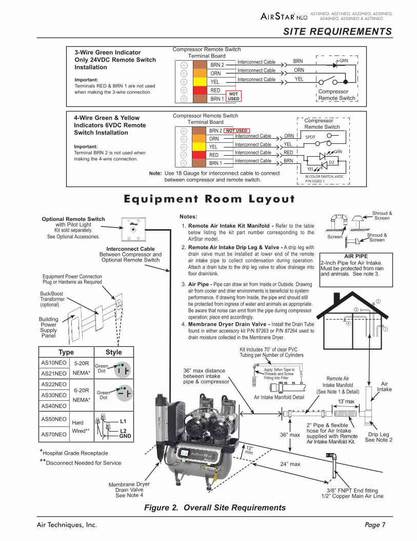
Figure 2. Overall Site Requirements
Equipment Room Layout
YELORN
BRN 2ORNYELREDBRN 1
Compressor Remote SwitchTerminal Board Compressor
Remote Switch
Interconnect CableInterconnect Cable
BRNInterconnect CableInterconnect Cable RED
YEL
GRN
D2
SPDT
BI COLOR SWITCH, 6VDCP/N 53202-1
Note: Use 18 Gauge for interconnect cable to connect between compressor and remote switch.
NOT USED
YEL
BRNORN
BRN 2ORNYELREDBRN 1
Compressor Remote SwitchTerminal Board
CompressorRemote Switch
Interconnect CableInterconnect Cable
Interconnect Cable GRN
NOT USED
4-Wire Green & Yellow Indicators 6VDC Remote Switch Installation
Important:Terminal BRN 2 is not used when making the 4-wire connection.
3-Wire Green Indicator Only 24VDC Remote Switch Installation
Important:Terminals RED & BRN 1 are not used when making the 3-wire connection.
3/8” FNPT End fitting1/2” Copper Main Air Line
36” max
2” Pipe & flexible hose for Air Intake supplied with Remote Air Intake Manifold Kit.
13” max
AIR PIPE2-Inch Pipe for Air Intake. Must be protected from rain and animals. See note 3.
Shroud & Screen
Screen Shroud & Screen
Remote Air Intake Manifold
(See Note 1 & Detail)
Optional Remote Switch with Pilot LightKit sold separately.
See Optional Accessories.
Air Intake
24” max
12” min
36” max distance between intake pipe & compressor
Interconnect Cable Between Compressor and Optional Remote Switch
Drip Leg See Note 2
Membrane Dryer Drain Valve See Note 4
1
4
3
2
Buck/Boost Transformer (optional)
Equipment Power Connection Plug or Hardwire as Required
Type StyleAS10NEO 5-20R
NEMA*AS21NEO
AS22NEO6-20R
NEMA*AS30NEO
AS40NEO
AS50NEO Hard Wired**AS70NEO
*Hospital Grade Receptacle
**Disconnect Needed for Service
Green Dot
L1
L2GND
Green Dot
Building PowerSupply Panel
Notes:1. Remote Air Intake Kit Manifold - Refer to the table
below listing the kit part number corresponding to the AirStar model.
2. Remote Air Intake Drip Leg & Valve - A drip leg with drain valve must be installed at lower end of the remote air intake pipe to collect condensation during operation. Attach a drain tube to the drip leg valve to allow drainage into floor drain/sink.
3. Air Pipe - Pipe can draw air from Inside or Outside. Drawing air from cooler and drier environments is beneficial to system performance. If drawing from Inside, the pipe end should still be protected from ingress of water and animals as appropriate. Be aware that noise can emit from the pipe during compressor operation; place end accordingly.
4. Membrane Dryer Drain Valve - Install the Drain Tube found in either accessory kit P/N 87263 or P/N 87264 used to drain moisture collected in the Membrane Dryer.
Air Intake Manifold Detail
Apply Teflon Tape to Threads and Screw Fitting Into Filter
Kit includes 70” of clear PVC Tubing per Number of Cylinders
Air Techniques, Inc.Page 8
AS10NEO, AS21NEO, AS22NEO, AS30NEO, AS40NEO, AS50NEO & AS70NEO
INSTALLATION INFORMATION
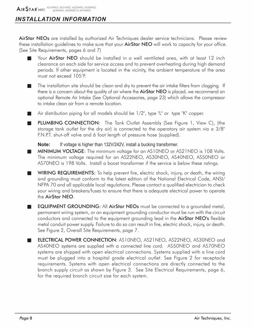
AirStar NEOs are installed by authorized Air Techniques dealer service technicians . Please review these installation guidelines to make sure that your AirStar NEO will work to capacity for your office . (See Site Requirements, pages 6 and 7)
Your AirStar NEO should be installed in a well ventilated area, with at least 12 inch clearance on each side for service access and to prevent overheating during high demand periods . If other equipment is located in the vicinity, the ambient temperature of the area must not exceed 105°F .
The installation site should be clean and dry to prevent the air intake filters from clogging . If there is a concern about the quality of air where the AirStar NEO is placed, we recommend an optional Remote Air Intake (See Optional Accessories, page 23) which allows the compressor to intake clean air from a remote location .
Air distribution piping for all models should be 1/2", type "L" or type "K" copper .
PLUMBING CONNECTION: The Tank Outlet Assembly (See Figure 1, View C), (the storage tank outlet for the dry air) is connected to the operatory air system via a 3/8" F .N .P .T . shut-off valve and 6 foot length of pressure hose (supplied) .
Note: If voltage is higher than 132V/242V, install a bucking transformer. MINIMUM VOLTAGE: The minimum voltage for an AS10NEO or AS21NEO is 108 Volts .
The minimum voltage required for an AS22NEO, AS30NEO, AS40NEO, AS50NEO or AS70NEO is 198 Volts . Install a boost transformer if the service is below these ratings .
WIRING REQUIREMENTS: To help prevent fire, electric shock, injury, or death, the wiring and grounding must conform to the latest edition of the National Electrical Code, ANSI/NFPA 70 and all applicable local regulations . Please contact a qualified electrician to check your wiring and breakers/fuses to ensure that there is adequate electrical power to operate the AirStar NEO .
EQUIPMENT GROUNDING: All AirStar NEOs must be connected to a grounded metal, permanent wiring system, or an equipment grounding conductor must be run with the circuit conductors and connected to the equipment grounding lead in the AirStar NEO's flexible metal conduit power supply . Failure to do so can result in fire, electric shock, injury, or death . See Figure 2, Overall Site Requirements, page 7 .
ELECTRICAL POWER CONNECTION: AS10NEO, AS21NEO, AS22NEO, AS30NEO and AS40NEO systems are supplied with a connected line cord . AS50NEO and AS70NEO systems are shipped with open electrical connections . Systems supplied with a line cord must be plugged into a hospital grade electrical outlet . See Figure 2 for receptacle requirements . Systems with open electrical connections are directly connected to the branch supply circuit as shown by Figure 3 . See Site Electrical Requirements, page 6, for the required branch circuit size for each system .

Page 9Air Techniques, Inc.
AS10NEO, AS21NEO, AS22NEO, AS30NEO, AS40NEO, AS50NEO & AS70NEO
POST INSTALLATION CHECK Make Sure Everything Is Running ProperlyAfter your AirStar NEO has been installed and before it is put into operation, be sure to follow the check-out procedure detailed below:
Check that Intake Filter(s) are fully seated into the compressor head(s) and that the Tank Outlet Valve is closed .
Turn on the electricity . Check that the supply voltage remains above the minimum defined in the Site Requirements section while the AirStar NEO is running . If the supply voltage drops below the minimum confirm site main circuit breaker and wire size . If both are acceptable, install a boost transformer .
Check pump-up and recovery times .
Turn on the AirStar NEO’s power and determine the pump-up time from 0 to 115 PSI .
Drain the storage tank to 80 PSI and determine the recovery time from 85 to 115 PSI .
If the pump-up or recovery time exceeds the duration listed by the table below, call an authorized dealer for service .
INSTALLATION INFORMATION
Note:AS40NEO has a single and dual head motor. Recovery time differs depending which is used. The longer recovery time occurs when using a single head motor. The shorter recovery time occurs when using dual head motors.
Model Number of Motors/Heads
Maximum Pump-up Time0-115 PSI (M:SS)
Maximum Recovery Time85-115 PSI (M:SS)
(See Note)
AS10NEO 1/1 5:15 1:20
AS21NEO 1/2 2:35 0:40
AS22NEO 1/2 2:35 0:40
AS30NEO 2/2 2:41 1:38
AS40NEO(See Note)
2/3 2:542:581:06
AS50NEO 2/4 2:20 1:27
AS70NEO 3/6 2:30 2:33
Figure 3. Electrical Connection Box
L1
L2
GREEN
WHITE
BLACK
GREEN GNDBLACK
WHITE
Important:Each system should have a
dedicated circuit panel .
Remove all power to the system prior to working with electrical circuits. Contacting high voltage can cause serious injury or even death.
All systems must be wired directly from an electrical box that complies with local electrical codes.
Air Techniques, Inc.Page 10
AS10NEO, AS21NEO, AS22NEO, AS30NEO, AS40NEO, AS50NEO & AS70NEO
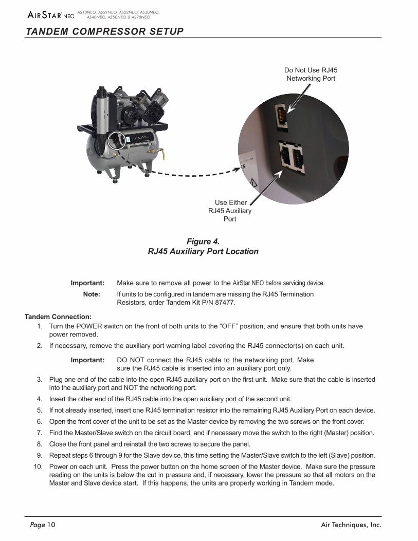
Use Either RJ45 Auxiliary
Port
Do Not Use RJ45 Networking Port
Figure 4. RJ45 Auxiliary Port Location
TANDEM COMPRESSOR SETUP
Important: Make sure to remove all power to the AirStar NEO before servicing device.Note: If units to be configured in tandem are missing the RJ45 Termination
Resistors, order Tandem Kit P/N 87477.
Tandem Connection:1. Turn the POWER switch on the front of both units to the “OFF” position, and ensure that both units have
power removed.2. If necessary, remove the auxiliary port warning label covering the RJ45 connector(s) on each unit.
Important: DO NOT connect the RJ45 cable to the networking port. Make sure the RJ45 cable is inserted into an auxiliary port only.
3. PlugoneendofthecableintotheopenRJ45auxiliaryportonthefirstunit.Makesurethatthecableisinsertedinto the auxiliary port and NOT the networking port.
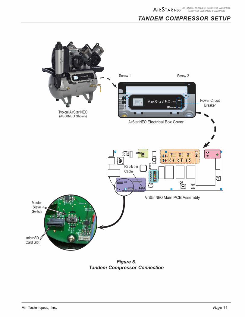
4. Insert the other end of the RJ45 cable into the open auxiliary port of the second unit.5. If not already inserted, insert one RJ45 termination resistor into the remaining RJ45 Auxiliary Port on each device.6. Open the front cover of the unit to be set as the Master device by removing the two screws on the front cover.7. Find the Master/Slave switch on the circuit board, and if necessary move the switch to the right (Master) position.8. Close the front panel and reinstall the two screws to secure the panel.9. Repeat steps 6 through 9 for the Slave device, this time setting the Master/Slave switch to the left (Slave) position.
10. Power on each unit. Press the power button on the home screen of the Master device. Make sure the pressure reading on the units is below the cut in pressure and, if necessary, lower the pressure so that all motors on the Master and Slave device start. If this happens, the units are properly working in Tandem mode.
Page 11Air Techniques, Inc.
AS10NEO, AS21NEO, AS22NEO, AS30NEO, AS40NEO, AS50NEO & AS70NEO
Master Slave Switch
AirStar NEO Main PCB Assembly
R i b b o n Cable
Ribbon to Display
Screw 1 Screw 2
Power Circuit Breaker
AirStar NEO Electrical Box Cover
Typical AirStar NEO(AS50NEO Shown)
microSD Card Slot
Figure 5. Tandem Compressor Connection
TANDEM COMPRESSOR SETUP
Air Techniques, Inc.Page 12
AS10NEO, AS21NEO, AS22NEO, AS30NEO, AS40NEO, AS50NEO & AS70NEO
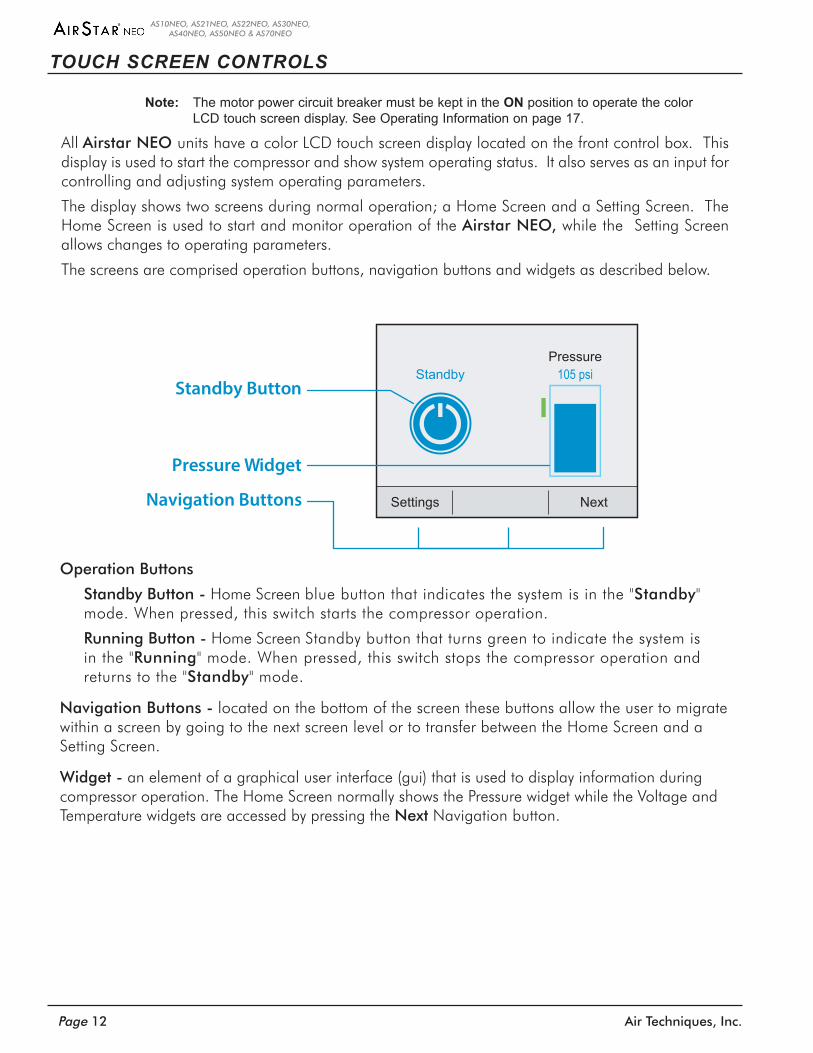
Note: The motor power circuit breaker must be kept in the ON position to operate the color LCD touch screen display. See Operating Information on page 17.
All Airstar NEO units have a color LCD touch screen display located on the front control box . This display is used to start the compressor and show system operating status . It also serves as an input for controlling and adjusting system operating parameters .
The display shows two screens during normal operation; a Home Screen and a Setting Screen . The Home Screen is used to start and monitor operation of the Airstar NEO, while the Setting Screen allows changes to operating parameters .
The screens are comprised operation buttons, navigation buttons and widgets as described below .
TOUCH SCREEN CONTROLS
Operation Buttons
Standby Button - Home Screen blue button that indicates the system is in the "Standby" mode . When pressed, this switch starts the compressor operation .
Running Button - Home Screen Standby button that turns green to indicate the system is in the "Running" mode . When pressed, this switch stops the compressor operation and returns to the "Standby" mode .
Navigation Buttons - located on the bottom of the screen these buttons allow the user to migrate within a screen by going to the next screen level or to transfer between the Home Screen and a Setting Screen .
Widget - an element of a graphical user interface (gui) that is used to display information during compressor operation . The Home Screen normally shows the Pressure widget while the Voltage and Temperature widgets are accessed by pressing the Next Navigation button .
Settings Next
Pressure105 psiStandby
Standby Button
Navigation Buttons
Pressure Widget
Page 13Air Techniques, Inc.
AS10NEO, AS21NEO, AS22NEO, AS30NEO, AS40NEO, AS50NEO & AS70NEO
TOUCH SCREEN CONTROLS
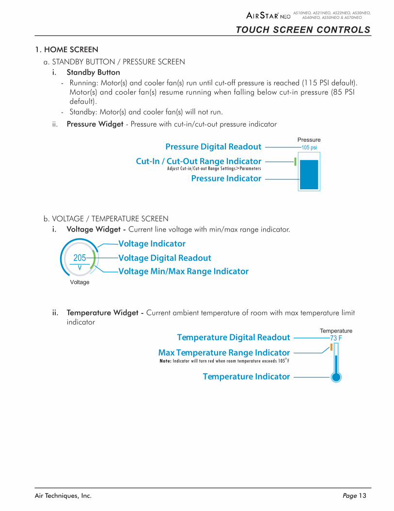
1. HOME SCREEN
a . STANDBY BUTTON / PRESSURE SCREENi. Standby Button
- Running: Motor(s) and cooler fan(s) run until cut-off pressure is reached (115 PSI default) . Motor(s) and cooler fan(s) resume running when falling below cut-in pressure (85 PSI default) .
- Standby: Motor(s) and cooler fan(s) will not run .
ii . Pressure Widget - Pressure with cut-in/cut-out pressure indicator
205v
Voltage
Voltage Indicator
Voltage Min/Max Range IndicatorVoltage Digital Readout
Temperature73 F
Temperature Indicator
Temperature Digital Readout
Max Temperature Range Indicator
b . VOLTAGE / TEMPERATURE SCREENi. Voltage Widget - Current line voltage with min/max range indicator .
ii. Temperature Widget - Current ambient temperature of room with max temperature limit indicator
Pressure105 psi
Cut-In / Cut-Out Range Indicator
Pressure Indicator
Pressure Digital Readout
Adjust Cut-in/Cut-out Range Settings>Parameters
Note: Indicator will turn red when room temperature exceeds 105ο F
Air Techniques, Inc.Page 14
AS10NEO, AS21NEO, AS22NEO, AS30NEO, AS40NEO, AS50NEO & AS70NEO
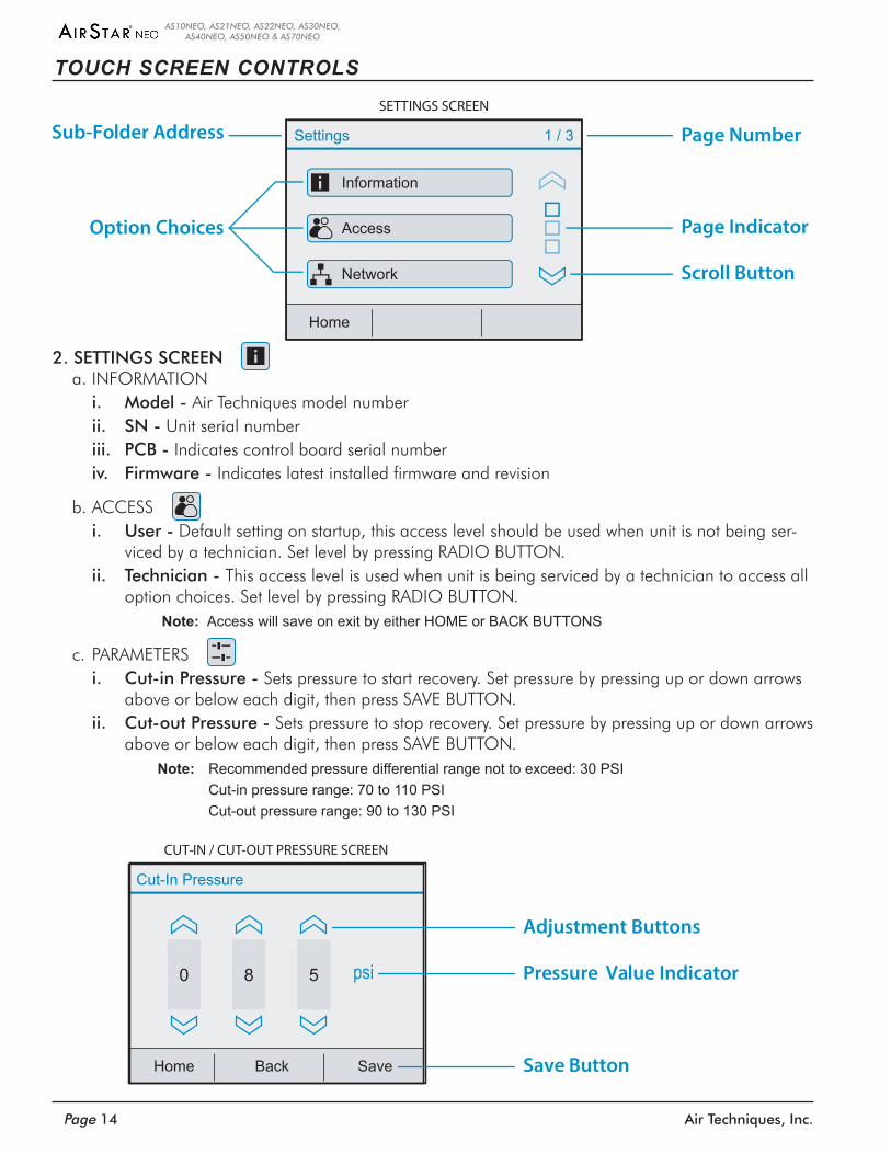
2. SETTINGS SCREENa . INFORMATION
i. Model - Air Techniques model numberii. SN - Unit serial numberiii. PCB - Indicates control board serial number iv. Firmware - Indicates latest installed firmware and revision
b . ACCESSi. User - Default setting on startup, this access level should be used when unit is not being ser-
viced by a technician . Set level by pressing RADIO BUTTON . ii. Technician - This access level is used when unit is being serviced by a technician to access all
option choices . Set level by pressing RADIO BUTTON .Note: Access will save on exit by either HOME or BACK BUTTONS
c . PARAMETERSi. Cut-in Pressure - Sets pressure to start recovery . Set pressure by pressing up or down arrows
above or below each digit, then press SAVE BUTTON . ii. Cut-out Pressure - Sets pressure to stop recovery . Set pressure by pressing up or down arrows
above or below each digit, then press SAVE BUTTON .Note: Recommended pressure differential range not to exceed: 30 PSI Cut-in pressure range: 70 to 110 PSI Cut-out pressure range: 90 to 130 PSI
Information
Access
Network
Home
Settings 1 / 3
SETTINGS SCREEN
Page Number
Scroll Button
Option Choices Page Indicator
Sub-Folder Address
Home
Cut-In Pressure
0
Back Save
psi58
CUT-IN / CUT-OUT PRESSURE SCREEN
Adjustment Buttons
Pressure Value Indicator
Save Button
TOUCH SCREEN CONTROLS
Page 15Air Techniques, Inc.
AS10NEO, AS21NEO, AS22NEO, AS30NEO, AS40NEO, AS50NEO & AS70NEO
TOUCH SCREEN CONTROLS
d . DATE / TIME
i. Date - Sets to current date . Set date by pressing up or down arrows above or below each digit, then press SAVE BUTTON .
ii. Time - Sets current time . Set time by pressing up or down arrows above or below each digit, then press SAVE BUTTON .
e . NETWORK
i. Hint: - Password “Hint”
ii. DHCP: - Indicates DHCP of connected network
iii. IP-Address: - Indicates IP-Adress of connected network
iv. Netmask: - Indicates Netmask of connected network
v. Gateway: - Indicates Gateway of connected network
vi. MAC Address: - Indicates MAC address of unit
f . SERVICE
Note:Donotresetclockuntilallfiltershavebeenreplaced.
i. Service Resets - Indicates time remaining before next suggested service . Pressing the MAINTENANCE PERFORMED BUTTON will reset clock .
ii. Force Run - When pressed, unit will run motor(s) and cooler fan(s) for thirty (30) seconds .
g . STATISTICS
i. On-Time - Shows time that unit has been powered on (hours)
ii. Run-Time - Shows time that unit has been running (hours)
iii. Duty Cycle - Shows percentage of Run-Time over On-Time (%) .
h . ALARM HISTORY
Shows the last forty (40) alarms triggered . Push any listed ALARM BUTTON to get details of alarm, such as suggested tasks and date alarm was triggered .
iii. Operation Mode - Sets mode of operation; Dental Office or CAD/CAM . Set mode by pressing RADIO BUTTON, then press SAVE BUTTON .
Note: CAD/CAM mode should be used when the unit is going to be used in a high duty cycle situation. Selecting CAD/CAM mode will shorten the activation time for additional compressor heads to assist in pressure recovery.
Air Techniques, Inc.Page 16
AS10NEO, AS21NEO, AS22NEO, AS30NEO, AS40NEO, AS50NEO & AS70NEO
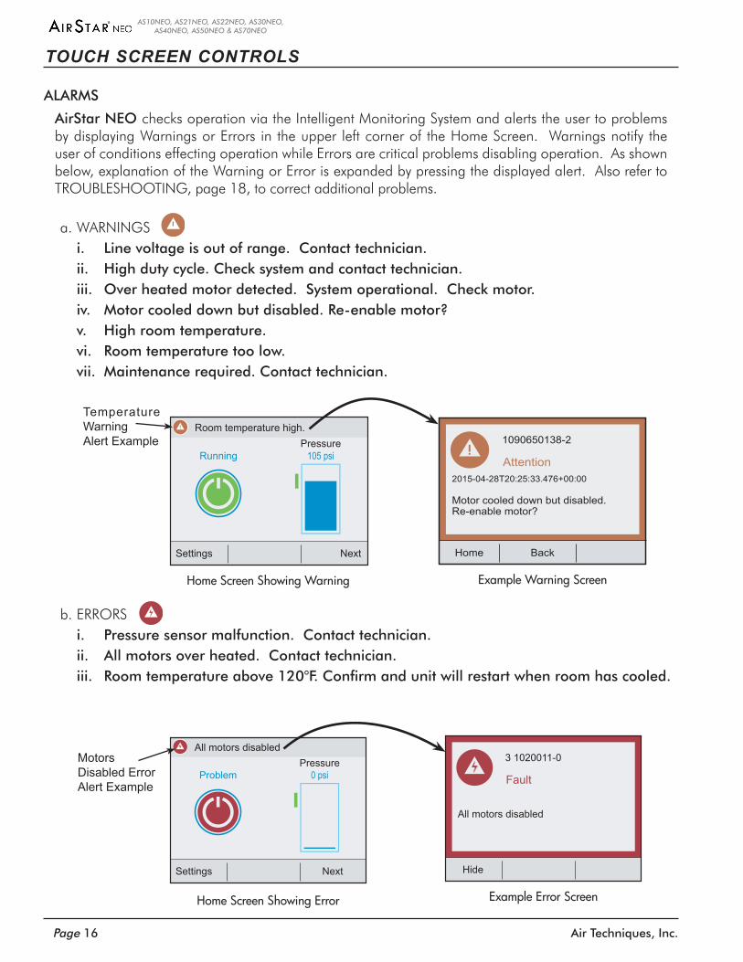
a . WARNINGSi. Line voltage is out of range. Contact technician.ii. High duty cycle. Check system and contact technician.iii. Over heated motor detected. System operational. Check motor. iv. Motor cooled down but disabled. Re-enable motor?v. High room temperature. vi. Room temperature too low. vii. Maintenance required. Contact technician.
Hide
Fault
3 1020011-0
All motors disabled
Settings Next
Pressure0 psiProblem
All motors disabled
b . ERRORSi. Pressure sensor malfunction. Contact technician.ii. All motors over heated. Contact technician.iii. Roomtemperatureabove120°F.Confirmandunitwillrestartwhenroomhascooled.
TOUCH SCREEN CONTROLS
ALARMS
AirStar NEO checks operation via the Intelligent Monitoring System and alerts the user to problems by displaying Warnings or Errors in the upper left corner of the Home Screen . Warnings notify the user of conditions effecting operation while Errors are critical problems disabling operation . As shown below, explanation of the Warning or Error is expanded by pressing the displayed alert . Also refer to TROUBLESHOOTING, page 18, to correct additional problems .
Home Back
Attention
1090650138-2
2015-04-28T20:25:33.476+00:00
Motor cooled down but disabled.Re-enable motor?
Settings Next
Pressure105 psiRunning
Room temperature high.
Home Screen Showing Warning Example Warning Screen
Temperature WarningAlert Example
MotorsDisabled ErrorAlert Example
Home Screen Showing Error Example Error Screen

Page 17Air Techniques, Inc.
AS10NEO, AS21NEO, AS22NEO, AS30NEO, AS40NEO, AS50NEO & AS70NEO
Note a: The motor power circuit breaker must be kept in the ON position and should not be used as a switch for the unit operation.
All Airstar NEO units can be operated from either the LCD touch screen or an optional remote switch . The motor Power circuit breaker on the face of the compressor control box must be set in the ON position whether using the touch screen or the optional remote switch . Since the Airstar NEO is designed for continuous operation, the motor Power circuit breaker should be kept in the ON position . Operate the Airstar NEO by performing either the touch screen or remote switch procedure below .
OPERATING INFORMATION
START UP BY TOUCH SCREEN 1 . Set the motor Power circuit breaker in the
ON position .2 . Observe that the color LCD touch screen dis-
play illuminates and depress the blue Standby button .
3 . Observe that the Standby button changes to a green Running button and that the unit is running and the Pressure widget shows increasing pressure .
START UP BY OPTIONAL REMOTE SWITCH1 . Set the motor Power circuit breaker to the ON
position .2 . Observe that when in Standby with no errors the
push button indicator is extinguished .Note b: Depending on the site installation, the
remote switch can be a single LED 24VDC switch or a Bi-Color LED 6VDC switch. Refer to the tables below for the LED conditions for each switch during operation.
3 . Depress the push button switch and observe that the associated indicator illuminates as listed for the corresponding switch .
6VDC Bi-Color Green / Yellow Indicators (See Note b.)
Bi-Color LED Condition Switch Position Condition Description
None Out Standby, No errors
Solid Green In Running, No errors
Flashing Yellow Out Standby, Error present
Alternating Green / Yellow In Running, Error present
24VDC Green Indicator Only (See Note b.)
Green LED Condition Switch Position Condition Description
None Out Standby, No errors
Solid Green In Running, No errors
Flashing Green – Slow Out Standby, Error present
Green – Fast In Running, Error present
Optional Remote Control Panel
Control Box
Motor Power Switch
(See Note a)
1
2
Color LCD Touch Screen Display
Control Box
Motor Power Switch
(See Note a above)
Settings Next
Pressure105 psiRunning
Settings Next
Pressure105 psiStandby
1
2
3
Air Techniques, Inc.Page 18
AS10NEO, AS21NEO, AS22NEO, AS30NEO, AS40NEO, AS50NEO & AS70NEO
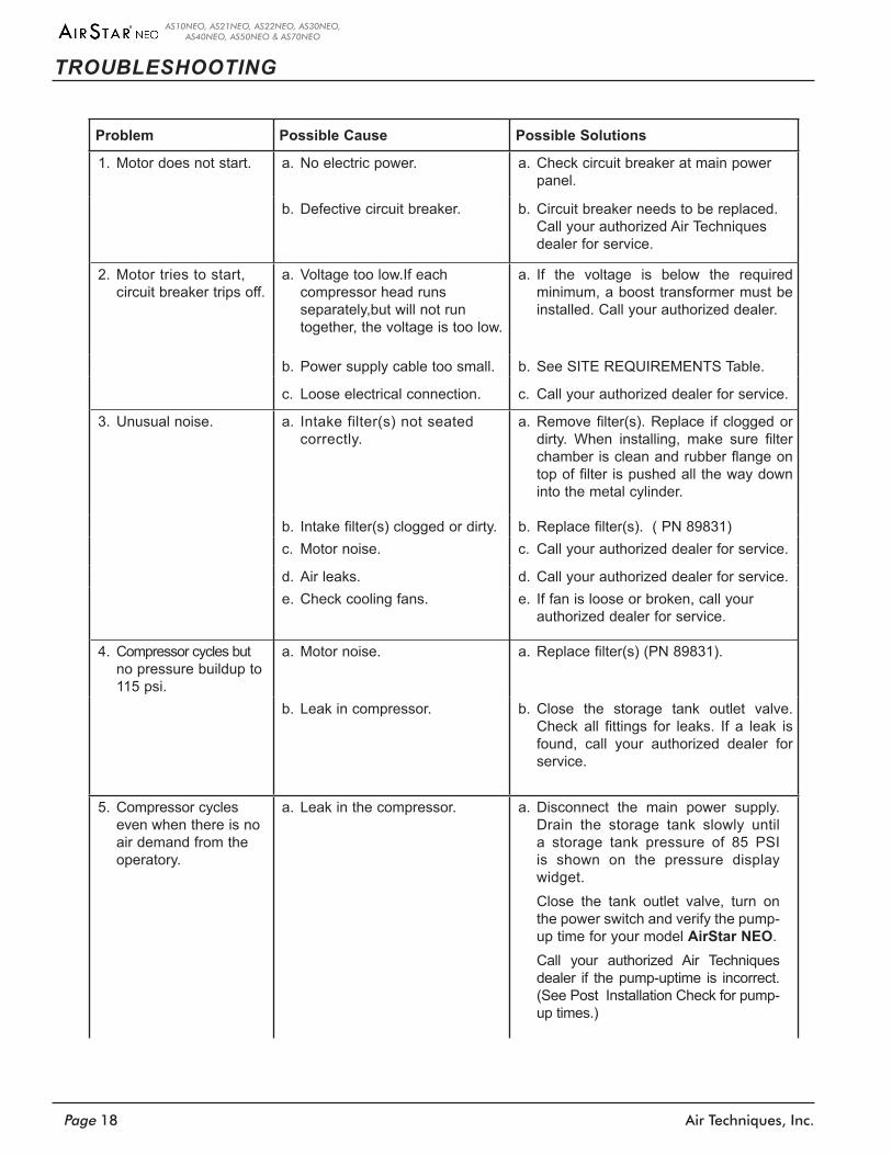
TROUBLESHOOTING
Problem Possible Cause Possible Solutions
1. Motor does not start. a. No electric power. a. Check circuit breaker at main power panel.
b. Defective circuit breaker. b. Circuit breaker needs to be replaced. Call your authorized Air Techniques dealer for service.
2. Motor tries to start, circuit breaker trips off.
a. Voltage too low.If each compressor head runs separately,but will not run together, the voltage is too low.
a. If the voltage is below the required minimum, a boost transformer must be installed. Call your authorized dealer.
b. Power supply cable too small. b. See SITE REQUIREMENTS Table.
c. Loose electrical connection. c. Call your authorized dealer for service.
3. Unusual noise. a. Intake filter(s) not seated correctly.
a. Remove filter(s). Replace if clogged or dirty. When installing, make sure filter chamber is clean and rubber flange on top of filter is pushed all the way down into the metal cylinder.
b. Intake filter(s) clogged or dirty. b. Replace filter(s). ( PN 89831)c. Motor noise. c. Call your authorized dealer for service.
d. Air leaks. d. Call your authorized dealer for service.e. Check cooling fans. e. If fan is loose or broken, call your
authorized dealer for service.
4. Compressor cycles but no pressure buildup to 115 psi.
a. Motor noise. a. Replace filter(s) (PN 89831).
b. Leak in compressor. b. Close the storage tank outlet valve. Check all fittings for leaks. If a leak is found, call your authorized dealer for service.
5. Compressor cycles even when there is no air demand from the operatory.
a. Leak in the compressor. a. Disconnect the main power supply. Drain the storage tank slowly until a storage tank pressure of 85 PSI is shown on the pressure display widget.
Close the tank outlet valve, turn on the power switch and verify the pump-up time for your model AirStar NEO.
Call your authorized Air Techniques dealer if the pump-uptime is incorrect. (See Post Installation Check for pump-up times.)
Page 19Air Techniques, Inc.
AS10NEO, AS21NEO, AS22NEO, AS30NEO, AS40NEO, AS50NEO & AS70NEO
TROUBLESHOOTING
Problem Possible Cause Possible Solutions
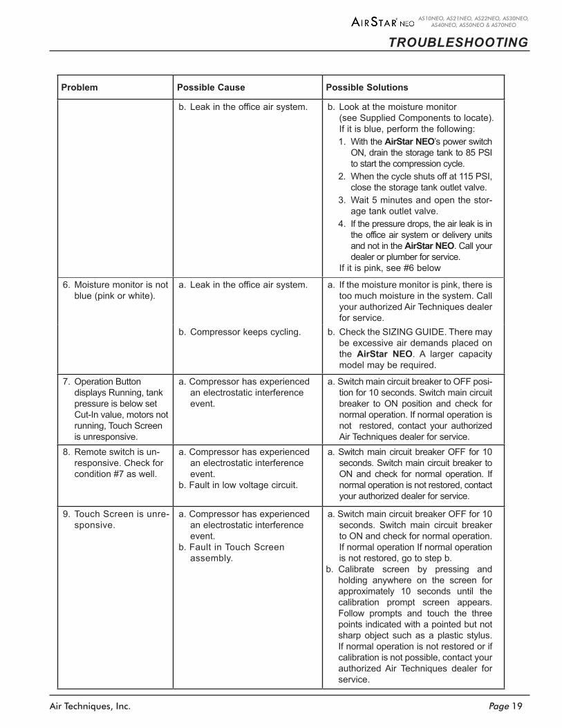
b. Leak in the office air system. b. Look at the moisture monitor (see Supplied Components to locate). If it is blue, perform the following:
1. With the AirStar NEO’s power switch ON, drain the storage tank to 85 PSI to start the compression cycle.
2. When the cycle shuts off at 115 PSI, close the storage tank outlet valve.
3. Wait 5 minutes and open the stor-age tank outlet valve.
4. If the pressure drops, the air leak is in the office air system or delivery units and not in the AirStar NEO. Call your dealer or plumber for service.
If it is pink, see #6 below
6. Moisture monitor is not blue (pink or white).
a. Leak in the office air system. a. If the moisture monitor is pink, there is too much moisture in the system. Call your authorized Air Techniques dealer for service.
b. Compressor keeps cycling. b. Check the SIZING GUIDE. There may be excessive air demands placed on the AirStar NEO. A larger capacity model may be required.
7. Operation Button displays Running, tank pressure is below set Cut-In value, motors not running, Touch Screen is unresponsive.
a. Compressor has experienced an electrostatic interference event.
a. Switch main circuit breaker to OFF posi-tion for 10 seconds. Switch main circuit breaker to ON position and check for normal operation. If normal operation is not restored, contact your authorized Air Techniques dealer for service.
8. Remote switch is un-responsive. Check for condition #7 as well.
a. Compressor has experienced an electrostatic interference event.
b. Fault in low voltage circuit.
a. Switch main circuit breaker OFF for 10 seconds. Switch main circuit breaker to ON and check for normal operation. If normal operation is not restored, contact your authorized dealer for service.
9. Touch Screen is unre-sponsive.
a. Compressor has experienced an electrostatic interference event.
b. Fault in Touch Screen assembly.
a. Switch main circuit breaker OFF for 10 seconds. Switch main circuit breaker to ON and check for normal operation. If normal operation If normal operation is not restored, go to step b.
b. Calibrate screen by pressing and holding anywhere on the screen for approximately 10 seconds until the calibration prompt screen appears. Follow prompts and touch the three points indicated with a pointed but not sharp object such as a plastic stylus. If normal operation is not restored or if calibration is not possible, contact your authorized Air Techniques dealer for service.
Air Techniques, Inc.Page 20
AS10NEO, AS21NEO, AS22NEO, AS30NEO, AS40NEO, AS50NEO & AS70NEO
Like all precision products, your AirStar NEO requires a certain amount of care on a regularly scheduled basis . A well-organized maintenance program aids dependable equipment operation and reduces problems to a minimum . Routine checks help to detect general overall wear, and replacement of parts can often be made before a problem occurs .
Understanding this, we have established minimum maintenance requirements listed below that include routine inspections and the replacement of filters using preventive maintenance kits available for the specific AirStar NEO model . Adherence to this recommended maintenance schedule will ensure that the equipment will continue performing at its best with uninterrupted service .
AirStar NEO also employs an Intelligent Monitoring System, that when prompted by a technician, performs a test for both Pump Up and Recovery Time . This not only makes diagnosing basic errors quick and simple, but also indicates if the problem is with the compressor or the operatory plumbing .
Routine Inspection - Monthly Clean exterior surfaces .
Check for abnormal noises and air leaks .
Make sure that no flammable, corrosive, or combustible materials are stored in the equipment room (especially in the area around the equipment) .
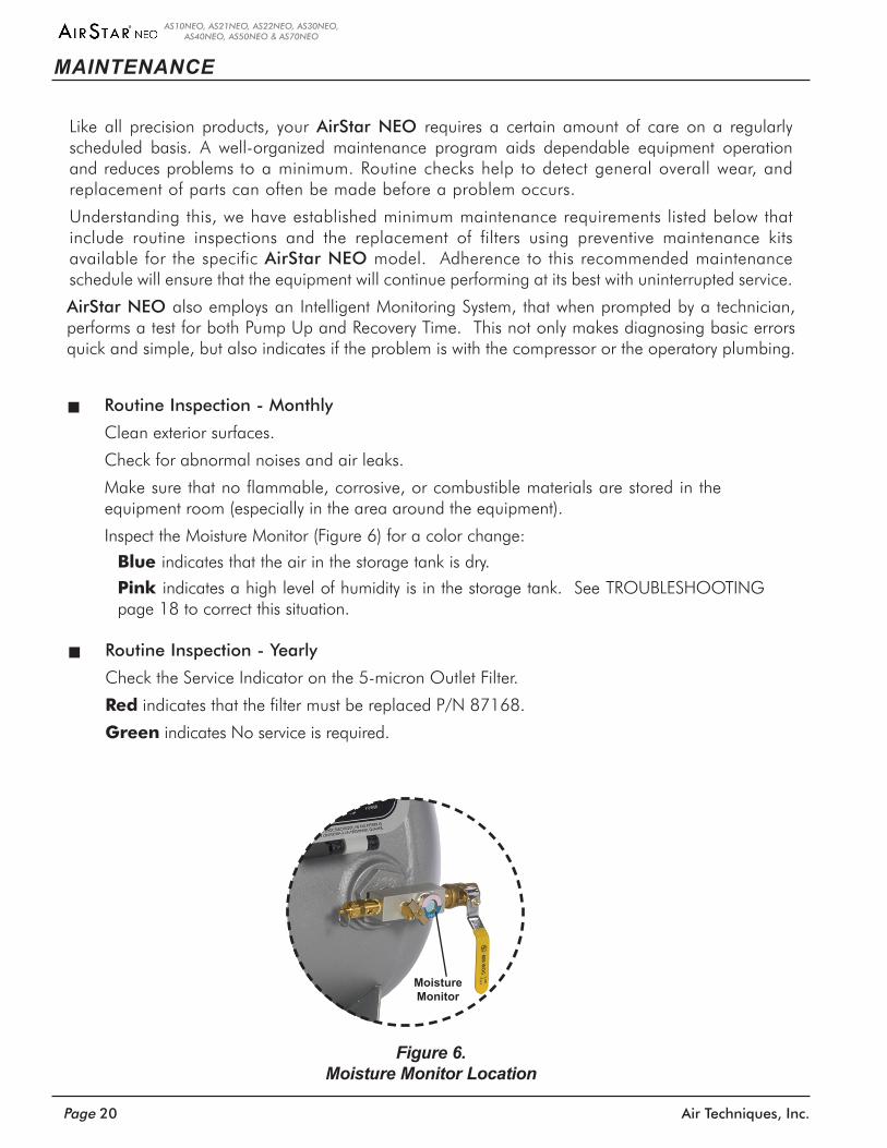
Inspect the Moisture Monitor (Figure 6) for a color change:
Blue indicates that the air in the storage tank is dry .
Pink indicates a high level of humidity is in the storage tank . See TROUBLESHOOTING page 18 to correct this situation .
Routine Inspection - Yearly Check the Service Indicator on the 5-micron Outlet Filter .
Red indicates that the filter must be replaced P/N 87168 .
Green indicates No service is required .
Figure 6. Moisture Monitor Location
MAINTENANCE
Moisture Monitor
Page 21Air Techniques, Inc.
AS10NEO, AS21NEO, AS22NEO, AS30NEO, AS40NEO, AS50NEO & AS70NEO
MAINTENANCE
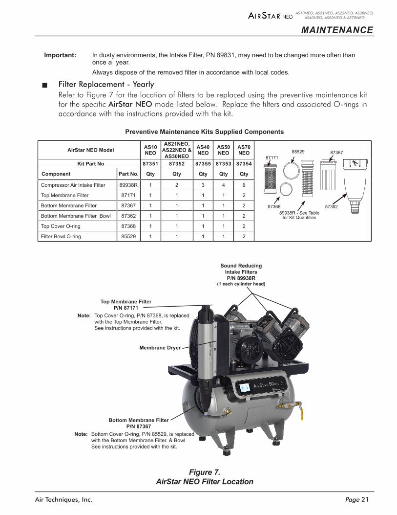
Important: In dusty environments, the Intake Filter, PN 89831, may need to be changed more often than once a year.
Always dispose of the removed filter in accordance with local codes.
Filter Replacement - Yearly Refer to Figure 7 for the location of filters to be replaced using the preventive maintenance kit for the specific AirStar NEO mode listed below . Replace the filters and associated O-rings in accordance with the instructions provided with the kit .
Preventive Maintenance Kits Supplied Components
AirStar NEO Model AS10 NEO
AS21NEO, AS22NEO & AS30NEO
AS40 NEO
AS50 NEO
AS70 NEO
Kit Part No 87351 87352 87355 87353 87354
Component Part No. Qty Qty Qty Qty Qty
Compressor Air Intake Filter 89938R 1 2 3 4 6
Top Membrane Filter 87171 1 1 1 1 2
Bottom Membrane Filter 87367 1 1 1 1 2
Bottom Membrane Filter Bowl 87362 1 1 1 1 2
Top Cover O-ring 87368 1 1 1 1 2
Filter Bowl O-ring 85529 1 1 1 1 2
Figure 7. AirStar NEO Filter Location
Sound ReducingIntake FiltersP/N 89938R
(1 each cylinder head)
Membrane Dryer
Top Membrane Filter P/N 87171
Bottom Membrane Filter P/N 87367
Note: Top Cover O-ring, P/N 87368, is replaced with the Top Membrane Filter. See instructions provided with the kit.
Note: Bottom Cover O-ring, P/N 85529, is replaced with the Bottom Membrane Filter. & Bowl See instructions provided with the kit.
8552987171
8736889938R - See Table
for Kit Quantities
87362
87367
Air Techniques, Inc.Page 22
AS10NEO, AS21NEO, AS22NEO, AS30NEO, AS40NEO, AS50NEO & AS70NEO
REPLACEMENT PARTS
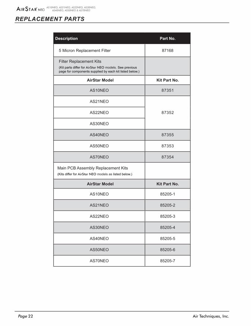
Description Part No.
5 Micron Replacement Filter 87168
Filter Replacement Kits(Kit parts differ for AirStar NEO models. See previous page for components supplied by each kit listed below.)
AirStar Model Kit Part No.
AS10NEO 87351
AS21NEO
87352AS22NEO
AS30NEO
AS40NEO 87355
AS50NEO 87353
AS70NEO 87354
Main PCB Assembly Replacement Kits(Kits differ for AirStar NEO models as listed below.)
AirStar Model Kit Part No.
AS10NEO 85205-1
AS21NEO 85205-2
AS22NEO 85205-3
AS30NEO 85205-4
AS40NEO 85205-5
AS50NEO 85205-6
AS70NEO 85205-7
Page 23Air Techniques, Inc.
AS10NEO, AS21NEO, AS22NEO, AS30NEO, AS40NEO, AS50NEO & AS70NEO
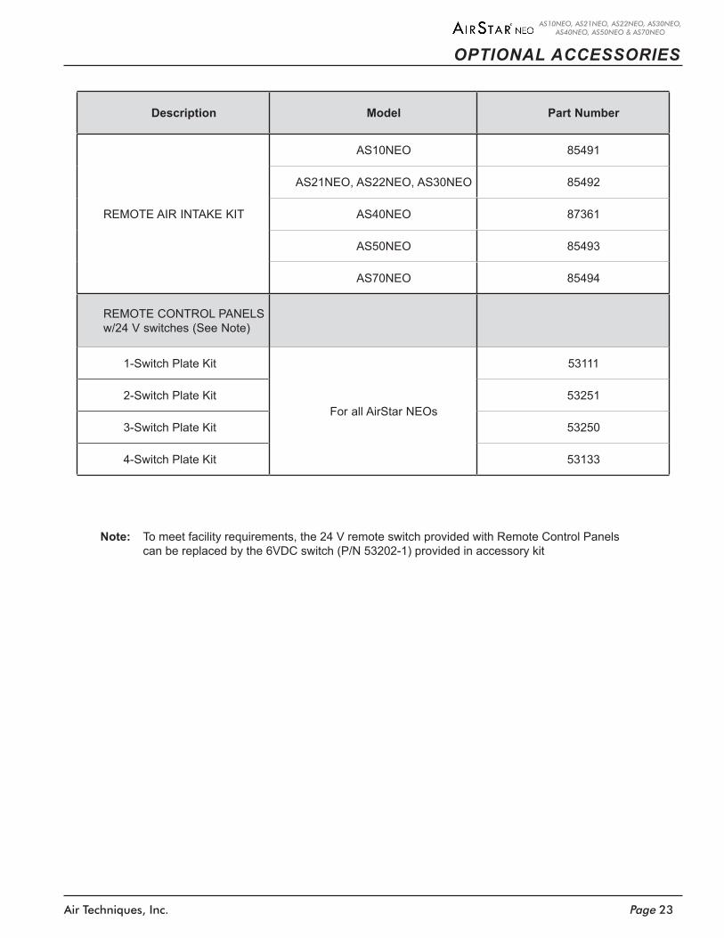
OPTIONAL ACCESSORIES
Description Model Part Number
REMOTE AIR INTAKE KIT
AS10NEO 85491
AS21NEO, AS22NEO, AS30NEO 85492
AS40NEO 87361
AS50NEO 85493
AS70NEO 85494
REMOTE CONTROL PANELSw/24 V switches (See Note)
1-Switch Plate Kit
For all AirStar NEOs
53111
2-Switch Plate Kit 53251
3-Switch Plate Kit 53250
4-Switch Plate Kit 53133
Note: To meet facility requirements, the 24 V remote switch provided with Remote Control Panels can be replaced by the 6VDC switch (P/N 53202-1) provided in accessory kit
Air Techniques, Inc.Page 24
AS10NEO, AS21NEO, AS22NEO, AS30NEO, AS40NEO, AS50NEO & AS70NEO
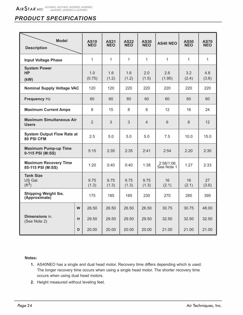
PRODUCT SPECIFICATIONS
AS10 NEO
AS21 NEO
AS22 NEO
AS30 NEO AS40 NEO AS50
NEOAS70 NEO
Input Voltage Phase 1 1 1 1 1 1 1
System PowerHP(kW)
1.0(0.75)
1.6(1.2)
1.6(1.2)
2.0(1.5)
2.6(1.95)
3.2(2.4)
4.8(3.6)
Nominal Supply Voltage VAC 120 120 220 220 220 220 220
Frequency Hz 60 60 60 60 60 60 60
Maximum Current Amps 8 15 8 8 12 16 24
Maximum Simultaneous Air Users 2 3 3 4 6 8 12
System Output Flow Rate at 80 PSI CFM 2.5 5.0 5.0 5.0 7.5 10.0 15.0
Maximum Pump-up Time 0-115 PSI (M:SS) 5:15 2:35 2:35 2:41 2:54 2.20 2:30
Maximum Recovery Time 85-115 PSI (M:SS) 1:20 0:40 0:40 1:38 2:58/1:06
See Note 1 1:27 2:33
Tank Size US Gal.(ft3)
9.75 (1.3)
9.75 (1.3)
9.75 (1.3)
9.75 (1.3)
16 (2.1)
16 (2.1)
27 (3.6)
Shipping Weight lbs. (Approximate) 175 185 185 230 270 285 395
Dimensions in. (See Note 2)
W 26.50 26.50 26.50 26.50 30.75 30.75 48.00
H 29.50 29.50 29.50 29.50 32.50 32.50 32.50
D 20.00 20.00 20.00 20.00 21.00 21.00 21.00
Description
Model
Notes:1. AS40NEO has a single and dual head motor. Recovery time differs depending which is used.
The longer recovery time occurs when using a single head motor. The shorter recovery time occurs when using dual head motors.
2. Height measured without leveling feet.
Page 25Air Techniques, Inc.
AS10NEO, AS21NEO, AS22NEO, AS30NEO, AS40NEO, AS50NEO & AS70NEO
WARRANTY
Quickly and easily register your new AirStar NEO on-line . Just have your product model and serial numbers available . Then go to the Air Techniques web site, www.airtechniques.com/dental, click the warranty registration link and complete the registration form . This on-line registration ensures a record for the warranty period and helps us keep you informed of product updates and other valuable information .
ON-LINE WARRANTY REGISTRATION
Each AirStar NEO is warranted to be free from defects in material and workmanship from the date of installation for a period of 60 months or 5,000 hours (whichever comes first):All part and component returns and replacement equipment require a Return Materials Authorization (RMA) . Returns must be received within three months of the RMA issue date and in appropriate pack-aging to prevent shipping damage . In case of advanced replacement, products shall be returned in the original packaging . Items returned without an RMA, or included with other products for which an RMA has been issued, will be returned to the customer at the discretion of Air Techniques, Inc .; the return shipping is the customer's responsibility .
Any item returned under warranty, will be repaired or replaced at our option at no charge provided that our inspection confirms it to be defective . Air Techniques, Inc . is not liable for indirect or con-sequential damages or loss of any nature in connection with this equipment . Dealer labor, shipping and handling charges are not covered by this warranty .
Warranty credit will not be applied to product returns that exhibit damage due to shipping, misuse, careless handling, and improper installation by dealers, or repairs by unauthorized personnel . Credit, or partial credit, will not be issued until products/parts have been received and assessed . If, after the evaluation it is determined that there is no-fault found and the unit is working prop-erly, a credit will not be issued . Warranty is void if product is installed incorrectly or installed or serviced by anyone other than an authorized Air Techniques' dealer or service personnel .
This warranty is in lieu of all other warranties expressed or implied . No representative or person is authorized to assume for us any liability in connection with the sale of our equipment .
Air Techniques, Inc.Page 26
AS10NEO, AS21NEO, AS22NEO, AS30NEO, AS40NEO, AS50NEO & AS70NEO
NOTES

AirStar is a registered trademark of Air Techniques, Inc .© 2015 Air Techniques, Inc . • P/N 87199, Rev . N • May 2021
www .air techniques .com
Corporate Headquarters1295 Walt Whitman Road | Melville, New York 11747- 3062
Phone: 800-247-8324 | Fax: 888-247-8481
Digital Imaging• Digital Radiography• Intraoral Camera• Caries Detection Aid• Intraoral X-ray• Panoramic X-ray• Film Processors
Utility Room • Dry Vacuums• Wet Vacuums• Air Compressors• Amalgam Separator• Utility Accessories• Utility Packages
Merchandise• Surface Disinfectant• Enzymatic Cleaner• Hand Sanitizer and Lotion• Waterline Cleaner• Evacuation System Cleaner• Imaging Accessories• Chemistry• Processor Accessories
For over 50 years, Air Techniques has been a leading innovator and manufacturer of dental products . Our priority is ensuring complete satisfaction by manufacturing reliable products and providing excellent customer and technical support . Whether the need is digital imaging, utility room equipment or merchandise, Air Techniques can provide the solution via our network of authorized professional dealers . Proudly designed, tested and manufactured in the U .S ., our products are helping dental professionals take their practices to the next level .
Air Techniques’ family of quality products for the dental professional include: