dental hygiene final proposal - the college of engineering
TRANSCRIPT
1
Dental Hygiene
Final Proposal
Team B Keenan Lacey Rodrigo Ojeda
Meshal Alrashidi
2017
Project Sponsor: NAU Faculty Advisor: Dr. Wade Sponsor Mentor: Tracye Moore and Amy Smith Instructor: Dr. Oman
2
DISCLAIMER This report was prepared by students as part of a university course requirement. While considerable effort has been put into the project, it is not the work of licensed engineers and has not undergone the extensive verification that is common in the profession. The information, data, conclusions, and content of this report should not be relied on or utilized without thorough, independent testing and verification. University faculty members may have been associated with this project as advisors, sponsors, or course instructors, but as such they are not responsible for the accuracy of results or conclusions.
3
Table of contents DISCLAIMER 2
1 BACKGROUND 5
1.1 Introduction 5
1.2 Project Description 5
1.3 Original System 5
1.3.1 Original System Structure 5
1.3.2 Original System Operation 6
1.3.3 Original System Performance 6
1.3.4 Original System Deficiencies 7
2.1 Customer Requirements (CRs) 7
2.2 Engineering Requirements (ERs) 8
2.3 Testing Procedures (TPs) 9
2.4 Design Links (DLs) 10
3 EXISTING DESIGNS 11
3.1 Design Research 12
3.2 System Level 12
3.2.1 Existing Design #1: Paint Mixer 12
3.2.2 Existing Design #2: Egg Beater 13
3.2.3 Existing Design #3:Sawzall 14
3.3 Subsystem Level 14
3.3.1 Subsystem #1: Paint Mixer 14
3.3.1.2 Existing Design #2: The Air Motor 14
3.3.1.3 Existing Design #3: Air Feed System 14
3.3.2 Subsystem #2: Egg Beater 15
3.3.2.1 Existing Design #1: Handle 15
3.3.2.2 Existing Design #2: Crank 15
3.3.2.3 Existing Design #3: Beaters 15
3.3.3 Subsystem #3: Sawzall 15
3.3.3.1 Existing Design #1: Electric motor 15
3.3.3.3 Existing Design #3:The Blade 15
4 DESIGNS CONSIDERED 16
4.1 Design #1:Gear design 16
4
4.2 Design #2:Quick Return Design 17
4.3 Design #3: Spinning Gear Design 18
4.4 Design #4: Chain Design 19
4.5 Design #5: Battery Operated Design 20
Figure 9: Battery Operated Design 20
4.7 Design #7: toothbrush design 22
4.8 Design #8: Springs Design 23
4.9 Design #9: Clapper design 24
4.10 Design #10: Two balls design 24
5 DESIGN SELECTED 27
5.1 Rationale for Design Selection 27
5.1.4 CR’s and the Final Design 29
6 PROPOSED DESIGN 33
6.1 Device Assembly 36 6.2 Budget and Schedule 36
7 Conclusion 36
5
1 BACKGROUND
1.1 Introduction This project consists of creating a dental triturator that will be battery powered. This device is used by a dentist or dental student to shake and mix a capsule made up of amalgam and glass ionomer sealant. This capsule contains liquids and metals used for teeth fillings. The problem with current triturator is that it requires electricity. Our client frequently travels to third world countries to give dental services to people in need. The problem is some of the places they go to do not have electricity. Our job is to design and build a dental triturator that does not require mains electricity to mix the dental capsules. This new triturator will help improve the lives of the users and many people in third world and foreign countries.
1.2 Project Description This section highlights the current problem and description of the project. The following is the original project description provided by the sponsor.
‘’A dental triturator is used to mix the components of dental capsules before certain dental procedures and they are usually powered by electricity. When dental hygiene students travel internationally, often times there is no electricity and/or the powered triturations are not compatible with international outlets. Collaboration between NAU’s Dental Hygiene (DH) Dept and NAU Mechanical Engineering Dept (CHHS and CEFNS) have created this Spring 2017 capstone project for 3-5 mechanical engineering students to create a human powered mixer that can shake a capsule for 10 seconds’’. [1]
1.3 Original System The original system for this project is an AC powered dental triturator called the Wig-l-Bug. A dental triturator is used to mix a capsule filled with amalgam and glass ionomer sealant. This specific capsule is mixed for a 10 seconds at “approximately” 4000 rpm to ensure that the capsules are properly mixed. This sealant is then used to fill cavities or holes in teeth.[2]
1.3.1 Original System Structure The dental triturator contains a motor, shaft, and rotational components that convert electrical energy to shake the capsule in a semi-linear motion. There are plastic bands that act as arms to

6
hold the capsule in place. Figure 1, shown below, contains the components of the original triturator. The triturator only allows one capsule at a time to ensure the mixture has the right viscosity. The internal components are some kind of metal or alloy and the cover and buttons are plastic.
Figure 1: Dental Tritrator Components
1.3.2 Original System Operation The team observed the active operation of the existing triturator while meeting with our client. We noticed that the motion was not directly linear but almost a figure eight motion. It was a non circular motion since a circular motion would separate the components of this capsule. The motion of the device was quick and the capsule was shaken for about 10 seconds. The capsule was then put into a tool and the components were squeezed out as a liquid. If the triturator does not do its job correctly then the capsule components remain unmixed or overmixed and it can not be used.
1.3.3 Original System Performance The function of the dental triturator is to shake a capsule at 4000 rpm for 10 seconds. When we observed the triturator, we timed it for 10 seconds but could not directly measure the rpm’s. The FujiTriage capsule calls for 4000 rpm but we estimate that the triturator may not always reach this requirement. Each capsule weighs around 2 grams and the triturator weighs on average 5 kilograms. The power requirements for the triturator are 115V and 60Hz. We assume a negligible amount of power is used for the buttons and lights so the majority of power is directly converted to the capsule. The triturator has a high efficiency since it is small and there is not
7
many parts. The energy required to properly mix the capsule is about 300 joules, calculation shown in Appendix B.
1.3.4 Original System Deficiencies The only deficiency with the dental triturator is that it is dependant on electricity. The Dental Hygiene Department wants a triturator that can be easily transported and used in countries that may not have electricity. 2 REQUIREMENTS This project requires us to engineer a dental triturator that is manually or battery operated. The current dental triturator is run on electricity(AC power) and this resource is not always available in other countries. The Dental Hygiene Department wants a triturator that can be run off of manual power such as a hand crank or DC electric power such as small battery. The triturator needs to function the same as the current triturator so that the user can do their job properly. The triturator will be engineered using the requirements below so that it can produce the proper results for the Dental Hygiene Department.
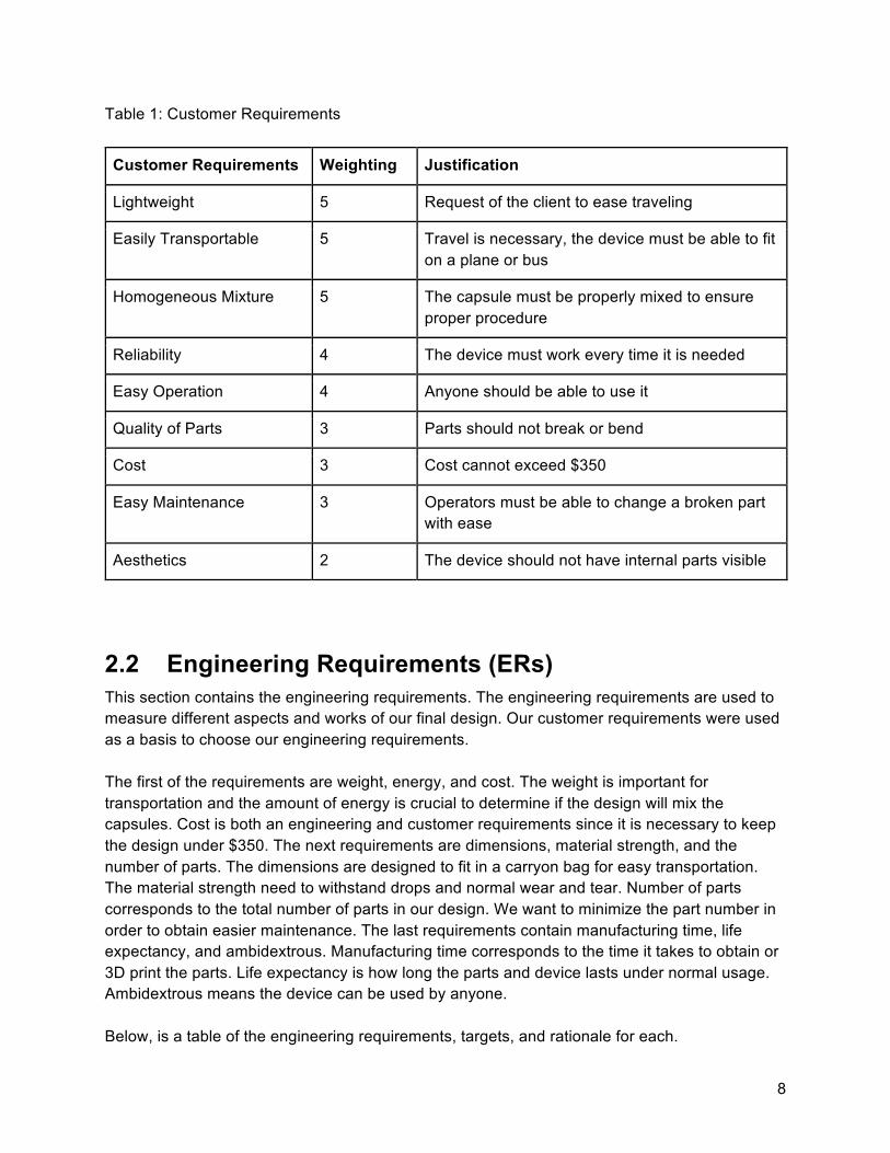
2.1 Customer Requirements (CRs) This section contains the customer requirements that are based off of what our client wants from the design. Lightweight, easy transportation, and homogeneous mixture are the top customer requirements so we gave them a ranking of 5 out of 5. The triturator will be lightweight so the user can carry it onto a plane, bus, or car. Also, it will fit in a small bag for easy carry. The triturator will have shake a capsule into a homogeneous mixture in order for the filling to be used, so this must be ranked with the highest weighting. Easy operation and reliability are the next customer requirements with a ranking of 4 out of 5. This project is not meant for a single person so we are going to make it easy to operate for any person who uses it. The triturator has to work every time it is needed and this will confirm that we develop a reliable design to satisfy our customer. The last customer requirements are quality of parts, cost, and easy maintenance with rankings of 3 out of 5. Aesthetics is also a requirement with a ranking of 2 out of 5. The triturator will have a few different parts and they may break or need to be changed in a few years. Maintenance on the device should be easy for all users and the parts should be easy to locate. The team will stay under budget by developing a triturator with low cost parts and fabrication. The quality of the parts have to satisfy the users and will have a lifespan of at least 1 year of moderate use. Aesthetics are ranked last since we do not need a good looking design in order for it to work.
8
Table 1: Customer Requirements
Customer Requirements Weighting Justification
Lightweight 5 Request of the client to ease traveling
Easily Transportable 5 Travel is necessary, the device must be able to fit on a plane or bus
Homogeneous Mixture 5 The capsule must be properly mixed to ensure proper procedure
Reliability 4 The device must work every time it is needed
Easy Operation 4 Anyone should be able to use it
Quality of Parts 3 Parts should not break or bend
Cost 3 Cost cannot exceed $350
Easy Maintenance 3 Operators must be able to change a broken part with ease
Aesthetics 2 The device should not have internal parts visible
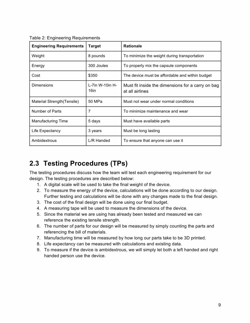
2.2 Engineering Requirements (ERs) This section contains the engineering requirements. The engineering requirements are used to measure different aspects and works of our final design. Our customer requirements were used as a basis to choose our engineering requirements. The first of the requirements are weight, energy, and cost. The weight is important for transportation and the amount of energy is crucial to determine if the design will mix the capsules. Cost is both an engineering and customer requirements since it is necessary to keep the design under $350. The next requirements are dimensions, material strength, and the number of parts. The dimensions are designed to fit in a carryon bag for easy transportation. The material strength need to withstand drops and normal wear and tear. Number of parts corresponds to the total number of parts in our design. We want to minimize the part number in order to obtain easier maintenance. The last requirements contain manufacturing time, life expectancy, and ambidextrous. Manufacturing time corresponds to the time it takes to obtain or 3D print the parts. Life expectancy is how long the parts and device lasts under normal usage. Ambidextrous means the device can be used by anyone. Below, is a table of the engineering requirements, targets, and rationale for each.
9
Table 2: Engineering Requirements
Engineering Requirements Target Rationale
Weight 8 pounds To minimize the weight during transportation
Energy 300 Joules To properly mix the capsule components
Cost $350 The device must be affordable and within budget
Dimensions L-7in W-10in H-16in
Must fit inside the dimensions for a carry on bag at all airlines
Material Strength(Tensile) 50 MPa Must not wear under normal conditions
Number of Parts 7 To minimize maintenance and wear
Manufacturing Time 5 days Must have available parts
Life Expectancy 3 years Must be long lasting
Ambidextrous L/R Handed To ensure that anyone can use it
2.3 Testing Procedures (TPs) The testing procedures discuss how the team will test each engineering requirement for our design. The testing procedures are described below:
1. A digital scale will be used to take the final weight of the device. 2. To measure the energy of the device, calculations will be done according to our design.
Further testing and calculations will be done with any changes made to the final design. 3. The cost of the final design will be done using our final budget. 4. A measuring tape will be used to measure the dimensions of the device. 5. Since the material we are using has already been tested and measured we can
reference the existing tensile strength. 6. The number of parts for our design will be measured by simply counting the parts and
referencing the bill of materials. 7. Manufacturing time will be measured by how long our parts take to be 3D printed. 8. Life expectancy can be measured with calculations and existing data. 9. To measure if the device is ambidextrous, we will simply let both a left handed and right
handed person use the device.
10
2.4 Design Links (DLs) The design links describe how the design meets each of the engineering requirements. The design links are listed below:
1. The weight of the design must be less than existing systems which is roughly 10 lbs. The final design’s total weight is projected to be less than 5 pounds, including all spare parts. Since the final design weight is less than existing systems, it will meet this requirement.
2. The energy required to mix a capsule properly is 300 Joules. With calculations for the final design, we are expecting to meet this requirement.
3. Required cost for the final design to be less than $350. The design is going to cost less than $100, so it does meet the cost requirement.
4. We are basing the dimension of our device and all spare parts on the maximum dimensions for a carryon bag for flying. The maximum dimensions for a carryon bag is 9” x 14” x 22”. Our design is going to fit inside of a carryon bag of dimensions 7.3" x 6.5" x 4.5".
5. The tensile strength of the chosen material will be 46 MPa. We are designing the material to handle drops and normal wear and tear since the design will not be under much stress during operation. Since there is not a large stress our strength of 46 MPa will meet our requirement.
6. The users want the design to be simple and have minimal parts for easy care and maintenance. The design will only have two components, which will meet our requirement.
7. The manufacturing time for the device should be as fast as possible to give users enough time to receive the parts needed. The toothbrush can be purchased at nearly any store and there will be a spare handy. The main component will be 3D printed in less than a few hours. Given these times, our design will meet this requirement.
8. The life expectancy the design should be long lasting in order to be reliable for the clients. Toothbrushes last for years and batteries can last up to 2 weeks with heavy use. The 3D printed design is expected to last 3 years with normal wear and tear. The design overall should last at least 2 years which meets our requirement.
9. The device is to be used by anyone and easy to use. Since it is not left or right hand dominant, it will be ambidextrous and will meet the requirement.
2.5 House of Quality (HoQ) The house of quality shows our customer requirements, engineering requirements, and appropriate weightings. The HoQ shows how each engineering requirement relates to each customer requirement. We completed the weightings for each requirement with the approval of our client, shown in Appendix: A. The most important requirement is the weight of the device then followed by the energy required to mis the capsule.

11
Table 3. HoQ
3 EXISTING DESIGNS Existing designs are devices on the market that have a similar function to our device. There is a paint shaker that shakes paint in a similar way we need to shake our dental capsule. An eggbeater device uses manual power to rotationally mix all the cooking ingredients. A Sawzall moves its blades in a similar motion that we need to move our dental capsule.
12
3.1 Design Research Research has been done by an examining similar systems and searching the web. For the examination of similar systems portion of this report, the team used the original dental tritrator. After extensive research, the team chose three existing devices that are similar to the same system used by the electrical dental titrator.
3.2 System Level A dental tritrator is a device that mixes components of a dental capsule. Today, it can be found in almost every dental clinic. Three different devices that have a similar motion to the dental tritrator were studied, these devices are a paint mixer, egg beater, and sawzall. First, the paint mixer works with the necessary semi-linear motion which is the goal of our device. Second, the egg beater provides the concept of using the manual method to mix food. Finally, the sawzall provides a back and forth movement that can be used to accomplish our goal.
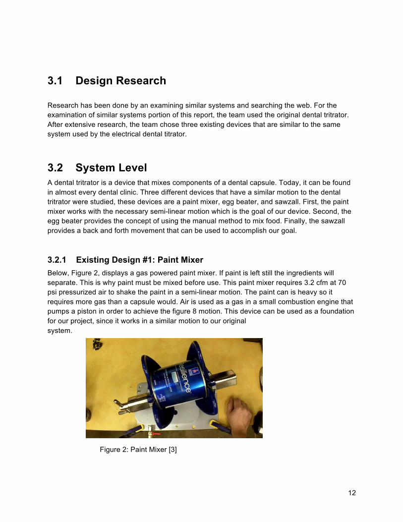
3.2.1 Existing Design #1: Paint Mixer Below, Figure 2, displays a gas powered paint mixer. If paint is left still the ingredients will separate. This is why paint must be mixed before use. This paint mixer requires 3.2 cfm at 70 psi pressurized air to shake the paint in a semi-linear motion. The paint can is heavy so it requires more gas than a capsule would. Air is used as a gas in a small combustion engine that pumps a piston in order to achieve the figure 8 motion. This device can be used as a foundation for our project, since it works in a similar motion to our original system.
Figure 2: Paint Mixer [3]

13
3.2.2 Existing Design #2: Egg Beater This design moves in a rotational or circular motion. This is an egg beater made from the company XOX. In the description, it says they have combined the idea of the egg beater and the smooth movement crank from a fishing rod. The device is human powered, so this means the speed of the crank differs. This design works by using the spinning holder and spin it. Then the metal in the bottom will rotates. This device related to our project because of its light weight.
Figure 3: Egg beater[4]

14
3.2.3 Existing Design #3:Sawzall The sawzall is an existing design that is used to cut different materials. The reason the sawzall is relevant to our project is because the movement of the Saw is back and forth. This movement can be used for our project. This device powered by rechargeable batteries.
Figure 4: Sawzall[5]
3.3 Subsystem Level In this section the team describes the system and subsystems of the existing designs we found. Each system and subsystems is explained how they work and why they are relevant to our project design.
3.3.1 Subsystem #1: Paint Mixer The paint mixer has multiple sub-systems. They consist of the base, the air motor, and the air feed system. Each subsystem was observed to find out how it works. 3.3.1.1 Existing Design #1: Base The base is a really important in this model because it holds the whole system together. In this particular model the base needs to be very sturdy because a gallon of paint weighs 11.3 pounds. When the paint is shaken it emits a tremendous moment and force that the base has to withstand.
3.3.1.2 Existing Design #2: The Air Motor The air motor is the most important subsystem in this item. Pressurized air is used as the working gas for the system. The air motor converts the power of the air into a kinetic energy. This kinetic energy is then used to shake the paint in a semi-linear motion.
3.3.1.3 Existing Design #3: Air Feed System

15
Air feed system is important because it allows the source of energy to enter the Paint mixer. There is a valve to manage the intake of the air on the motor. There is also a filter to keep contaminants from entering the motor.
3.3.2 Subsystem #2: Egg Beater Egg beater contains several subsystems that make it work. The subsystems are a plastic handle, crank, and beaters. This system does not require electricity to function and this is why it can help influence our design.
3.3.2.1 Existing Design #1: Handle A plastic handle is attached to the crank with a carved stainless steel block. The plastic handle is a source that is used to generate human energy into kinetic energy. This is done by rotating the handle using human power to make the egg beater work.
3.3.2.2 Existing Design #2: Crank The crank is the most important subsystem in the egg beater, and without it the entire device can not function. The most significant thing about the crank is the faster the crank rotates, the faster the beaters will rotate. This conversion of human energy is why it is related to this team’s project.
3.3.2.3 Existing Design #3: Beaters The beaters are the conclusion of the device, because they beat the eggs. They are made of stainless steel for safety reasons. The function of the beaters is achieved by rotating them in a high speed circular movement. The team has decided to convert the movement of the beaters from a circular way to a back and forth way. With this method, the team will find a key of success to the project design.
3.3.3 Subsystem #3: Sawzall The sawzall has a few main subsystems. The main ones are the Electric motor, the ANC gear drive, and the blade.
3.3.3.1 Existing Design #1: Electric motor The motor needs to produce high power and reliability so it has to be electrically powered. The sawzall conducts heavy duty cutting therefore the saw has to have much force and torque supplied to its motor. A rechargeable battery is what fuels the motor. 3.3.3.2 Existing Design #2: ANC Gear Drive The ANC Gear drive allows for the power of the electric motor to be converted into the back and forth motion of the saw. The gear drive is a set of gears and bearings that convert rotational motion from the motor to a linear motion.
3.3.3.3 Existing Design #3:The Blade
16
The blade is the simplest of the subsystems, but essential for the purpose of this device. The blade is what is used to cut the materials. The blade is where the linear motion is translated and we can observe the operation.
4 DESIGNS CONSIDERED This section contains ten designs we have considered to engineer a final product. We will explain the function and the parts of each design. We will also discuss the advantages and disadvantages of each design. The designs we have chosen are the best designs that the team has generated and meet our Engineering requirement and customer requirement . We will also explain the black box model and functional decomposition chart in this section to better understand the purpose of our design.
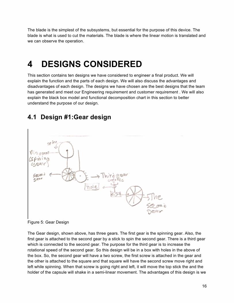
4.1 Design #1:Gear design
Figure 5: Gear Design The Gear design, shown above, has three gears. The first gear is the spinning gear. Also, the first gear is attached to the second gear by a stick to spin the second gear. There is a third gear which is connected to the second gear. The purpose for the third gear is to increase the rotational speed of the second gear. So this design will be in a box with holes in the above of the box. So, the second gear will have a two screw, the first screw is attached in the gear and the other is attached to the square and that square will have the second screw move right and left while spinning. When that screw is going right and left, it will move the top stick the and the holder of the capsule will shake in a semi-linear movement. The advantages of this design is we

17
can reach our desired speed with gears and it is easy to use. Disadvantages are the weight and the time to shake the capsule can be limited.
4.2 Design #2:Quick Return Design
Figure 6: Quick Return Design
This design contains a spinning gear in the middle of the design. The spinning gear has a screw on it that attaches to a rod. While spinning the gear the rod will move in a semi-linear motion. Also connected to another rod that makes the top holder move right and left “back and forth” movement. The advantage of this design is we can use any materials that can reach our engineering requirements like weight and quality. The disadvantage of this design is the speed to shake the capsule since we cannot add more gears.
18
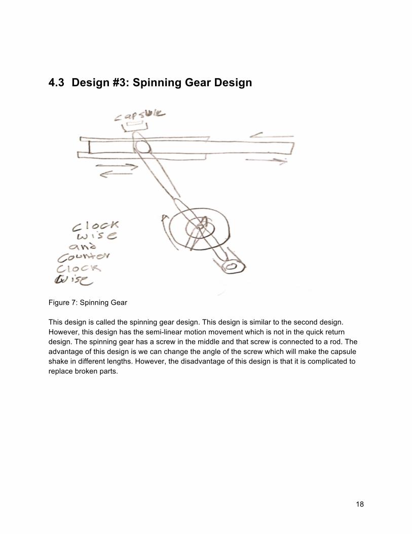
4.3 Design #3: Spinning Gear Design
Figure 7: Spinning Gear This design is called the spinning gear design. This design is similar to the second design. However, this design has the semi-linear motion movement which is not in the quick return design. The spinning gear has a screw in the middle and that screw is connected to a rod. The advantage of this design is we can change the angle of the screw which will make the capsule shake in different lengths. However, the disadvantage of this design is that it is complicated to replace broken parts.

19
4.4 Design #4: Chain Design
Figure 8: Chain design
This design called the chain design. This design can he used for both hands “left and right”. This design has two chains as shown in the figure above. It has three shaft on it. The purpose of using three shaft and two chains is to increase the speed of the shaking capsule. The top shaft is connected to the shake capsule. The advantage of this design is the team can increase or decrease the speed as the team can reach the required speed. The disadvantages of this design it will be a heavyweight design which our client while travel abroad seas and carry the project in a carry on luggage.
20
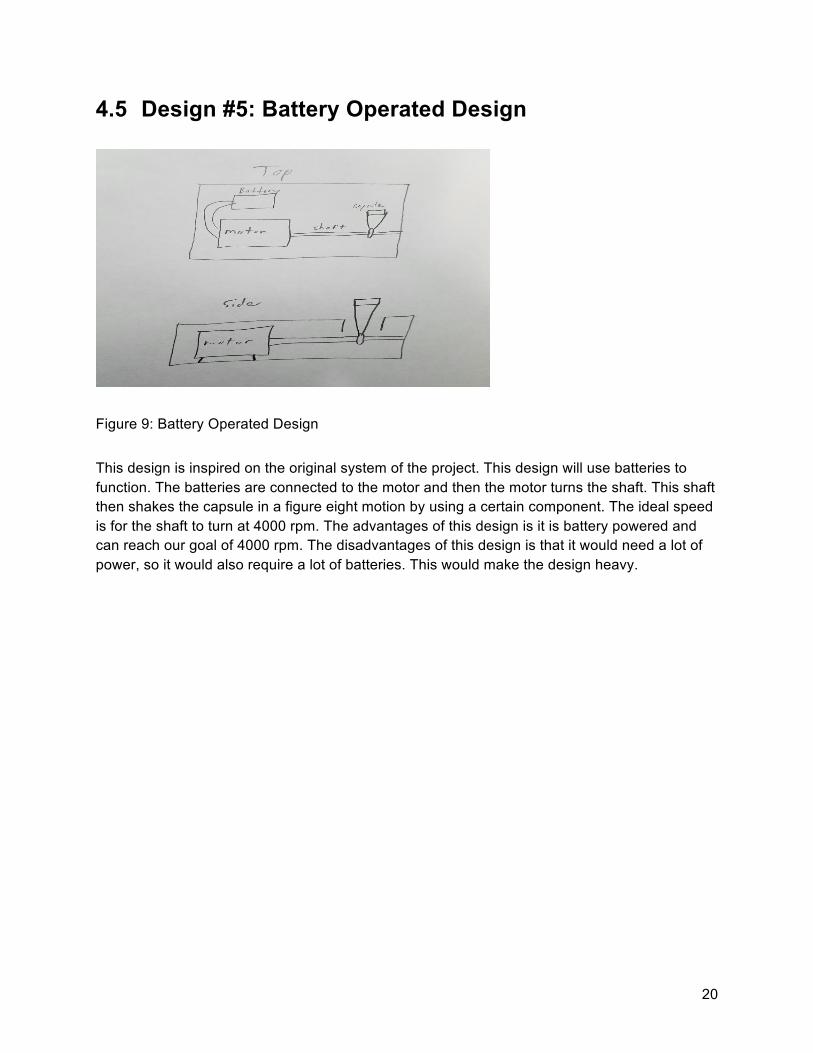
4.5 Design #5: Battery Operated Design
Figure 9: Battery Operated Design
This design is inspired on the original system of the project. This design will use batteries to function. The batteries are connected to the motor and then the motor turns the shaft. This shaft then shakes the capsule in a figure eight motion by using a certain component. The ideal speed is for the shaft to turn at 4000 rpm. The advantages of this design is it is battery powered and can reach our goal of 4000 rpm. The disadvantages of this design is that it would need a lot of power, so it would also require a lot of batteries. This would make the design heavy.
21
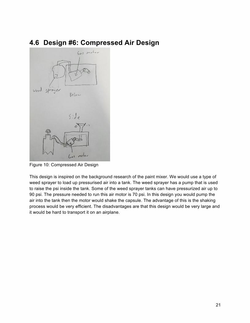
4.6 Design #6: Compressed Air Design
Figure 10: Compressed Air Design This design is inspired on the background research of the paint mixer. We would use a type of weed sprayer to load up pressurised air into a tank. The weed sprayer has a pump that is used to raise the psi inside the tank. Some of the weed sprayer tanks can have pressurized air up to 90 psi. The pressure needed to run this air motor is 70 psi. In this design you would pump the air into the tank then the motor would shake the capsule. The advantage of this is the shaking process would be very efficient. The disadvantages are that this design would be very large and it would be hard to transport it on an airplane.
22
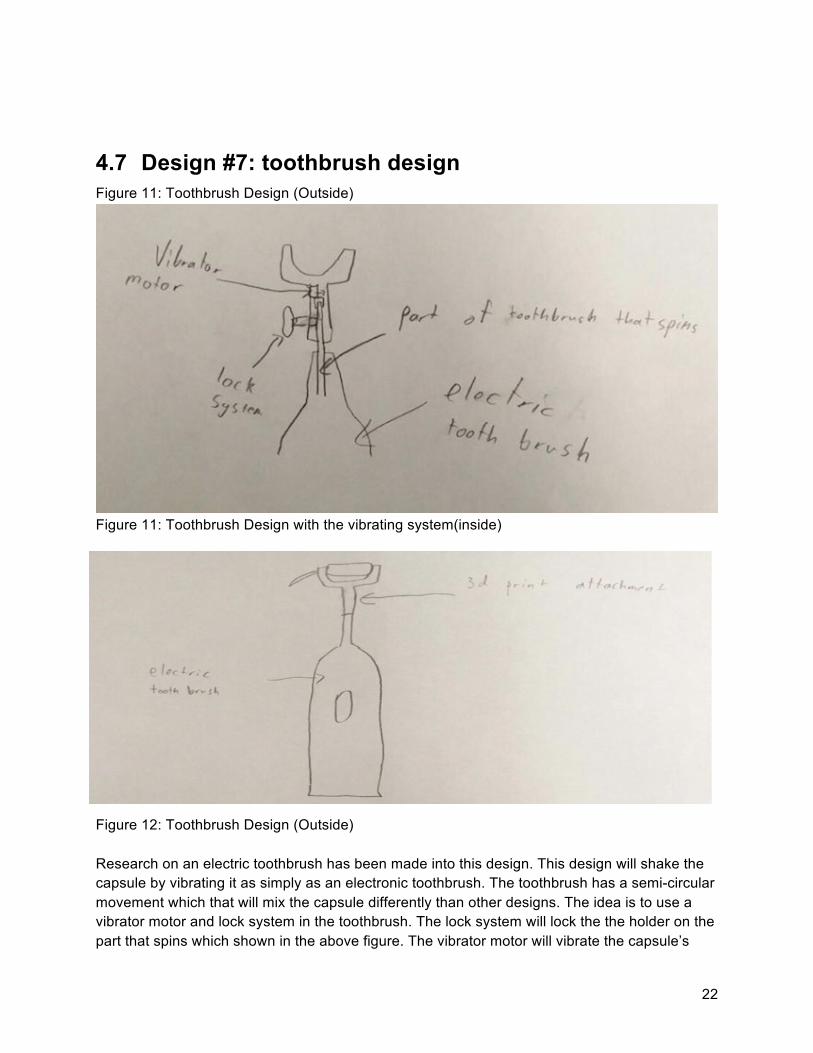
4.7 Design #7: toothbrush design Figure 11: Toothbrush Design (Outside)
Figure 11: Toothbrush Design with the vibrating system(inside)
Figure 12: Toothbrush Design (Outside) Research on an electric toothbrush has been made into this design. This design will shake the capsule by vibrating it as simply as an electronic toothbrush. The toothbrush has a semi-circular movement which that will mix the capsule differently than other designs. The idea is to use a vibrator motor and lock system in the toothbrush. The lock system will lock the the holder on the part that spins which shown in the above figure. The vibrator motor will vibrate the capsule’s
23
holder, and a human hand can turn it left and right then the capsule will be mixed. So, the advantages of this design are light weighted, easy to use, and a small size. The disadvantages of this design are non-fixable parts, hard replaceable parts and electricity used in this design.
4.8 Design #8: Springs Design
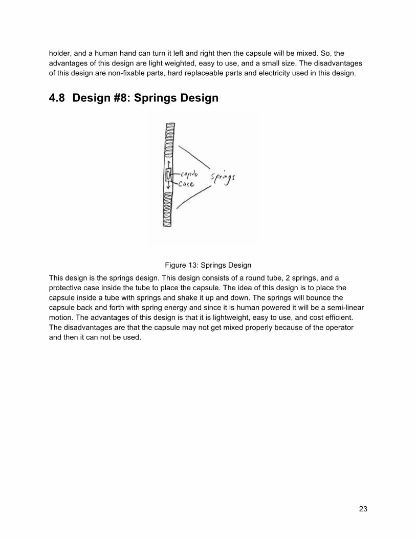
Figure 13: Springs Design
This design is the springs design. This design consists of a round tube, 2 springs, and a protective case inside the tube to place the capsule. The idea of this design is to place the capsule inside a tube with springs and shake it up and down. The springs will bounce the capsule back and forth with spring energy and since it is human powered it will be a semi-linear motion. The advantages of this design is that it is lightweight, easy to use, and cost efficient. The disadvantages are that the capsule may not get mixed properly because of the operator and then it can not be used.
24
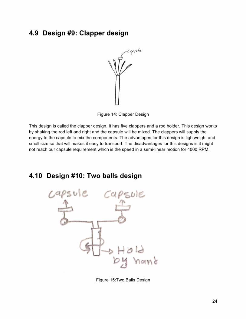
4.9 Design #9: Clapper design
Figure 14: Clapper Design
This design is called the clapper design. It has five clappers and a rod holder. This design works by shaking the rod left and right and the capsule will be mixed. The clappers will supply the energy to the capsule to mix the components. The advantages for this design is lightweight and small size so that will makes it easy to transport. The disadvantages for this designs is it might not reach our capsule requirement which is the speed in a semi-linear motion for 4000 RPM.
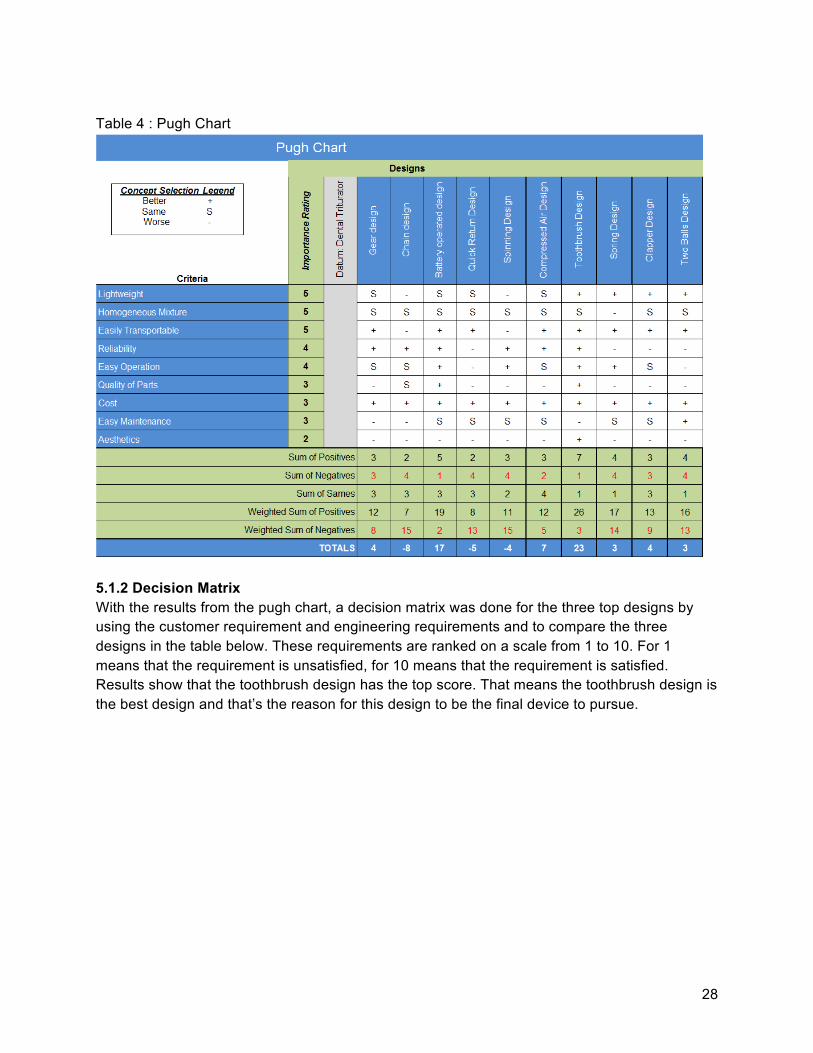
4.10 Design #10: Two balls design
Figure 15:Two Balls Design

25
As shown in the figure above, the team has considered a design containing two balls. This design is basically a hard rod with two connected ropes. The two ropes are attached to the balls. This design works by holding the hard rod and turn right and left by both hands. The advantages of this design are low cost and it can shake two capsules at the same time. The disadvantages of this device is people who use this design must use their both hands to make the capsules mixed.

26
4.11 Black box and Functional Model This section illustrates our black box and functional model. Our black box model shows the basic operation of what our device needs to do. That is to mix ingredients and produce a homogeneous mixture. The functional model shows what goes into mixing the capsule. It starts with a hand and human energy or electricity. The hand is used to hold the device and turn it on. Once activated the electricity or human energy will convert to linear motion and produce heat, noise, and energy. These models helps the user understand what the device is going to accomplish.
Figure 16: Black Box model
Figure 17: FunctionalDecompositionChart

27
5 DESIGN SELECTED After much research and design ideas for making a dental capsule shake and mix based on the engineering requirements and customer requirements, the team has decided to chose the toothbrush design as the final design. In the following section the team will discuss the design in details.
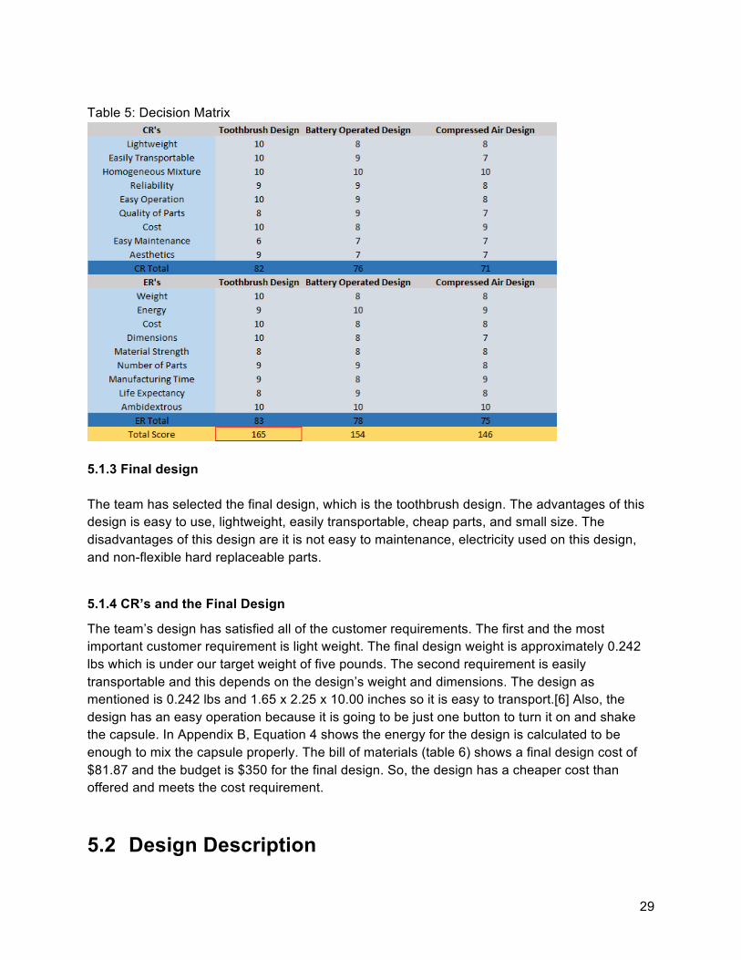
5.1 Rationale for Design Selection 5.1.1 Pugh chart The designs from section four were evaluated with a Pugh chart to determine the top ideas. As shown in the table below the team has provided the ten designs in the chart. Also, as shown, the pugh chart has the team’s customer requirements as the criteria. The designs were compared to the original design. After analysis, the team has chosen the top three designs based on their best total scores. For the first design, which is the toothbrush design, it got 23 points. The second design, which is the battery operated design, has 17 points. The third design is the compressed air design which has 7 points. These three designs will be presented in the team decision matrix.
28
Table 4 : Pugh Chart
5.1.2 Decision Matrix With the results from the pugh chart, a decision matrix was done for the three top designs by using the customer requirement and engineering requirements and to compare the three designs in the table below. These requirements are ranked on a scale from 1 to 10. For 1 means that the requirement is unsatisfied, for 10 means that the requirement is satisfied. Results show that the toothbrush design has the top score. That means the toothbrush design is the best design and that’s the reason for this design to be the final device to pursue.
29
Table 5: Decision Matrix
5.1.3 Final design The team has selected the final design, which is the toothbrush design. The advantages of this design is easy to use, lightweight, easily transportable, cheap parts, and small size. The disadvantages of this design are it is not easy to maintenance, electricity used on this design, and non-flexible hard replaceable parts.
5.1.4 CR’s and the Final Design
The team’s design has satisfied all of the customer requirements. The first and the most important customer requirement is light weight. The final design weight is approximately 0.242 lbs which is under our target weight of five pounds. The second requirement is easily transportable and this depends on the design’s weight and dimensions. The design as mentioned is 0.242 lbs and 1.65 x 2.25 x 10.00 inches so it is easy to transport.[6] Also, the design has an easy operation because it is going to be just one button to turn it on and shake the capsule. In Appendix B, Equation 4 shows the energy for the design is calculated to be enough to mix the capsule properly. The bill of materials (table 6) shows a final design cost of $81.87 and the budget is $350 for the final design. So, the design has a cheaper cost than offered and meets the cost requirement.
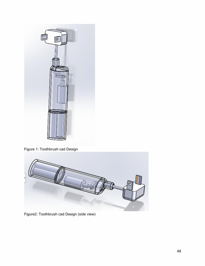
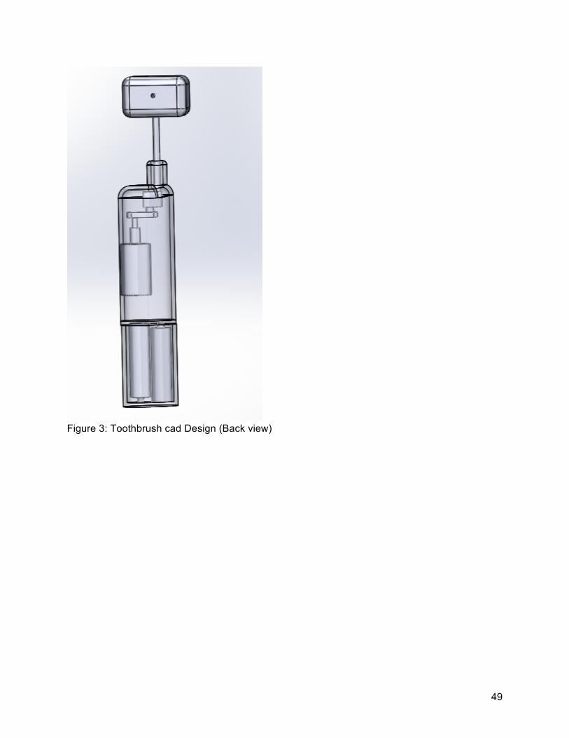
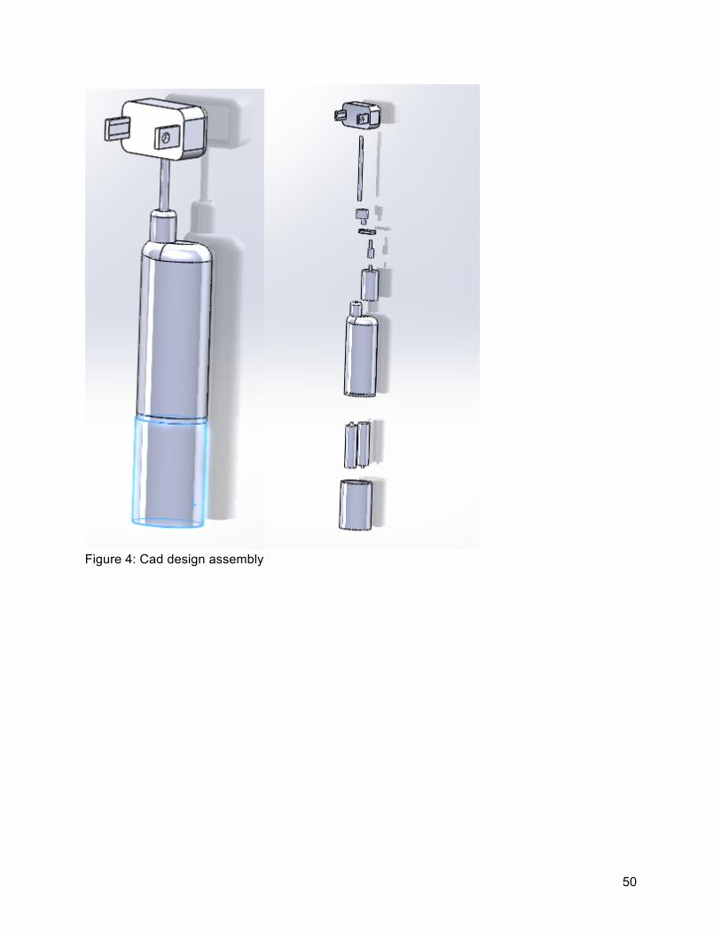
5.2 Design Description

30
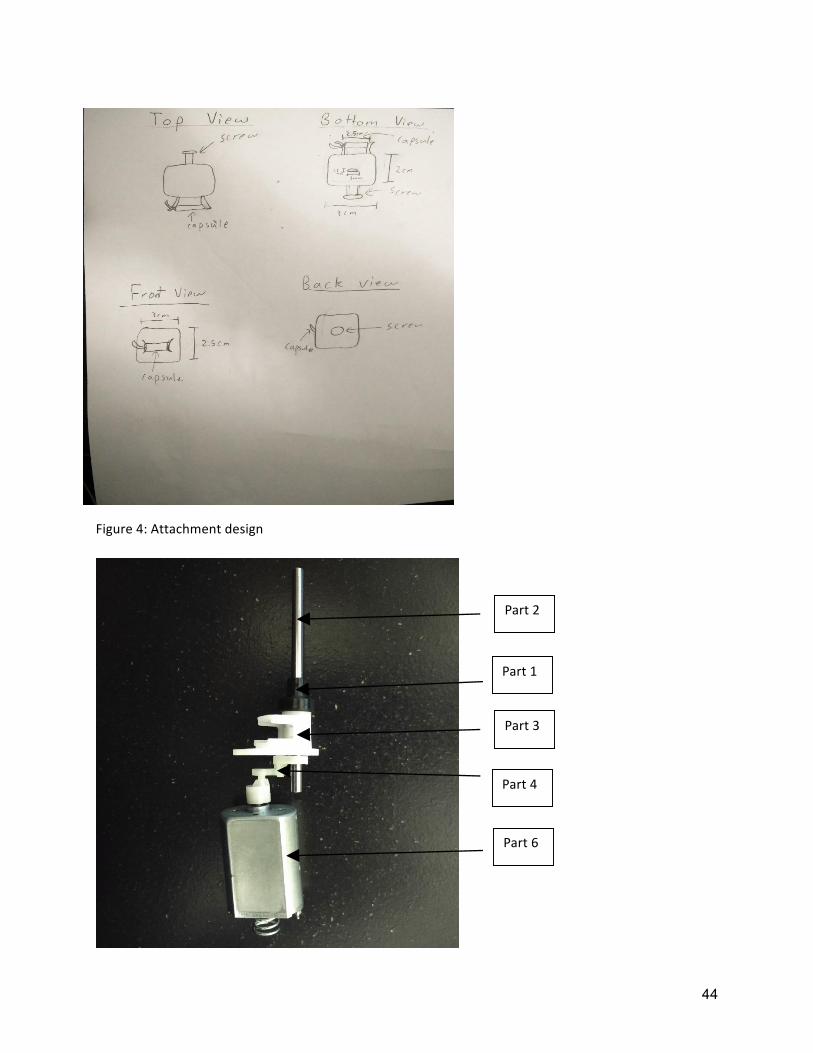
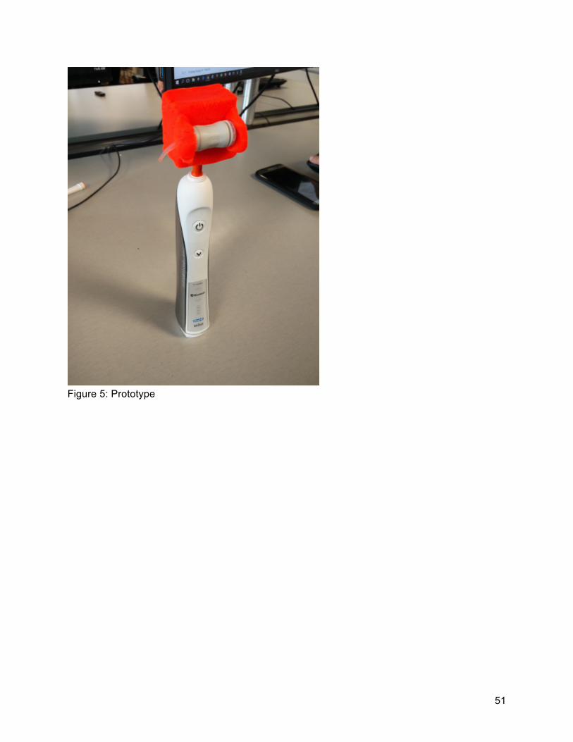
The final design proposed is the electric toothbrush design. A full diagram of our final design is in Appendix D. This design has two main components, the extension and the electric toothbrush. 5.2.1 Extension Model in SolidWorks Figure 18 is a picture of the attachment piece designed. This figure shows all the dimensions in inches. This piece will go on top of the electronic toothbrush. The piece will be 3D printed. The material we will be using for this is Acrylonitrile Butadiene Styrene (ABS). This is a great material because it is a inexpensive and a durable plastic. It has a glass transition of 105 °C (221 °F) *, Typical Injection Molding Temperature is between 204 - 238 °C (400 - 460 °F) *. Also, 98 °C (208 °F) for Heat Deflection Temperature (HDT) at 46 MPa (66 PSI). Also, It would stay two hours at 180°F to be dried. It has 46 MPa (6600 PSI) Tensile Strength and 74 MPa (10800 PSI) Flexural Strength[7]. It has a tensile strength of 46 Mpa and a high melting point of 105 degrees C. As shown in figure 18 the bottom view has an opening that is shaped in a semicircular way. This part will be placed on the metal shaft of the electric toothbrush. This particular shaft moves in a semicircular motion. Figure 18 shows the back view of the extension. The hole seen from this view will have a screw. This screw will tighten into the metal shaft thus creating stability between the extension and the toothbrush. This stability is key to transmitting the energy of the shaft to the capsule. Figure 5 Appendix D shows a picture of our prototype.
Figure 18: Capsules holder design 5.2.2 Electric Tooth Brush The second component of our design is the electric toothbrush. The electric toothbrush is complicated but we know it can is the key to the success of our project. Table 1 Appendix C is the bill of materials of our design project. Figure 1 in the appendix D shows an extruded version of our electronic toothbrush. Each component is different and has a different function. Figure 3, shows all the different components and what number is used to describe them. This figure also

31
has a ruler so each component can roughly be compared to inches and centimeters. Parts 11, 12, and 10 are the outside parts of the toothbrush they are the base that hold the rest of the pieces together. Part 9 is the brush itself but for our project we won’t need it. Parts 8 are the batteries used for the toothbrush. It uses two double AA batteries. Part 7 is the on and off switch of the toothbrush. Part 6 is the motor, (shown in Figure 6). At the end of the motor there is a little plastic tip that is used to convert the rotational energy to semi rotation. Part 5 and 3 act as a case where part 4 transmits the motors rotational energy to the metal shaft (part 2). The end of the shaft of part two is flat. One can see this more clearly in Figure 7 of the appendix C. Part 4 resembles a figure eight and is made of plastic. Part 1 is attached to the metal shaft and acts as a stopper to keep the shaft steady.
Figure 19: Toothbrush assembly
Figure 20 : Toothbrush Shaft

32
Figure 21: Part 4 5.2.3 Design Explanation The metal shaft in Figure 20 rotates in a semicircular way. This is crucial to the mixing of our capsule because we need to shake it in a semi linear rotation for it to work. If we try to mix the capsule using rotational motion this will only be detrimental to the mixture of the capsule. Rotational motion tends to separates mixtures which is the opposite of what we want to accomplish. The hardest part of this design is converting the motors rotational energy to the shafts semi-rotational motion. Although part 4 is very small it is the key in converting the motors rotational energy to the semicircular energy. Figure 22 shows how parts 1,2,3,4, and 6 are assembled. This assembly shows where the rotational motion is changed to semicircular motion. The plastic tip that is attached to the motors shaft attaches to one of the holes of part 4. The toothbrush metal shaft (part two) has a little plastic piece that attaches to the other hole of part 4. As the motor spins in a circle it pushes part 4 up and down thus making the metal shaft only move up and down. This creates the semi-rotational motion.
Figure 22: Shaft Assembly 5.2.4 Calculations To find the energy needed to mix the capsule properly, the original system was first observed. The Wig-l-Bug is the original system so a reverse engineering method was necessary to find out what was on the inside. The motor’s power requirements are 115 V and 1 amp (AC). This motor

33
transfers the power to a shaft and then a manufactured piece where the capsule is secured and shook in a figure 8 motion. Since the motor directly transfers its power to the capsule the team calculated the basic electric power equation P = V*I*PF, where P is power, V is volts, I is amps, and PF is the power factor. Doing this calculation, Figure 23 , the capsule gets about 345 Joules of energy from this device.
P = 115V * 1A * 0.3 = 34.5 Watts
E = 34.5 Watts * 10s = 345 Joules Figure 23: Power and Energy Equation 1
Now, looking at the specifications given by the GC FujiTriage company for this specific capsule, they state that the capsule should be mixed for 10 seconds at “approximately” 4000 rpm. Using the Wig-l-bug and the power equation P = (T*Speed)/9.5488 the energy required is about 290 Joules, Figure 24 . Since many tritrators are similar in size and speed, the designated energy is a minimum of 300 Joules to mix the capsules properly.
P = 0.0693Nm * 4000 RPM / 9.5488 = 29.03 Watts
E = 29.03 Watts * 10s = 290 Joules Figure 24: Power and Energy Equation 2
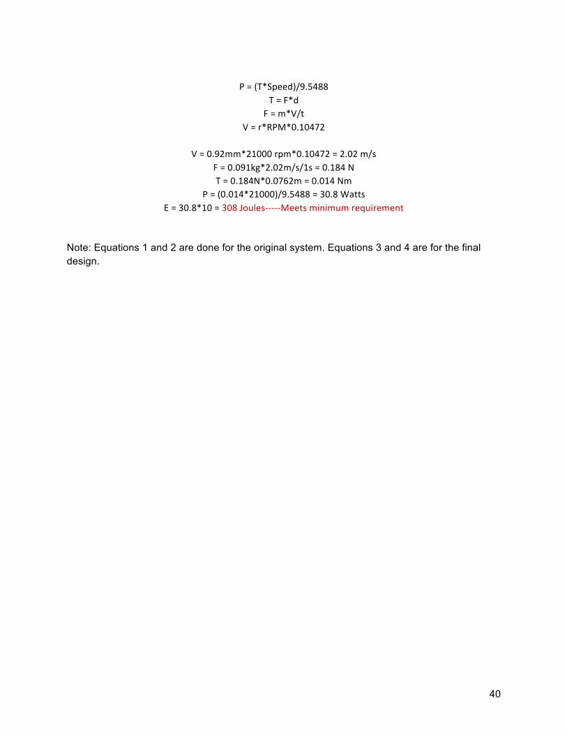
5.2.5 Results The final proposed design for the project is a Ranir electric toothbrush. The toothbrush does a back and forth motion along a half circle. Most electric toothbrushes have a frequency of 200-400 Hz and 24,000 - 48,000 movements per minute [8]. The design chosen contains a 350 Hz frequency in order to mix properly. To calculate the energy the used equation was the power equation P = (T*Speed)/9.5488. Tests will be done to make sure that the capsule can be mixed for more than 10 seconds. Appendix B shows the calculations done to find the rpm and Hz. Figure 4, in appendix B, shows the calculation executed by the team. According to these calculations 308 Joules will be transferred to the capsule in ten seconds from our design. To get the capsule to mix properly we need to transfer only 300 joules. Therefore these calculations supply the design will work.
6 PROPOSED DESIGN 6.1 Device Assembly For the proposed design, the capsule needs a minimum of 300 Joules to mix the components. In addition to the toothbrush, figure 25, shows model of the assembly. The goal is to 3D print the extension to make the capsule attach more easily to then be shaken. The design requires two AA batteries to be powered[9]. To make the design smaller, this type of toothbrush was chosen
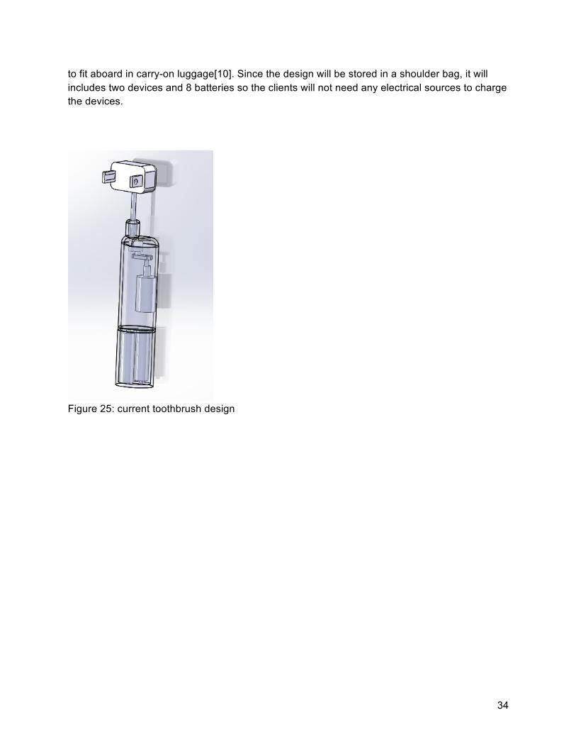
34
to fit aboard in carry-on luggage[10]. Since the design will be stored in a shoulder bag, it will includes two devices and 8 batteries so the clients will not need any electrical sources to charge the devices.
Figure 25: current toothbrush design
35
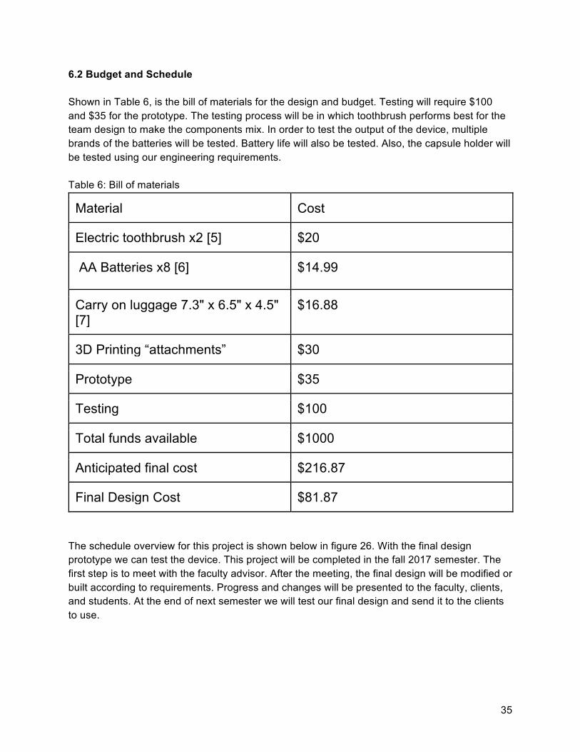
6.2 Budget and Schedule Shown in Table 6, is the bill of materials for the design and budget. Testing will require $100 and $35 for the prototype. The testing process will be in which toothbrush performs best for the team design to make the components mix. In order to test the output of the device, multiple brands of the batteries will be tested. Battery life will also be tested. Also, the capsule holder will be tested using our engineering requirements. Table 6: Bill of materials
Material Cost
Electric toothbrush x2 [5] $20
AA Batteries x8 [6] $14.99
Carry on luggage 7.3" x 6.5" x 4.5" [7]
$16.88
3D Printing “attachments” $30
Prototype $35
Testing $100
Total funds available $1000
Anticipated final cost $216.87
Final Design Cost $81.87 The schedule overview for this project is shown below in figure 26. With the final design prototype we can test the device. This project will be completed in the fall 2017 semester. The first step is to meet with the faculty advisor. After the meeting, the final design will be modified or built according to requirements. Progress and changes will be presented to the faculty, clients, and students. At the end of next semester we will test our final design and send it to the clients to use.

36
Figure 26: Fall 2017 Schedule Overview
7 Conclusion After much research and analysis, a final design was chosen. An electric toothbrush with an attachment for the dental capsule is chosen the final design. This design meets the proposed customer and engineering requirements better than any other design. Going forward, this design will be tested and modified to the better satisfy the requirements. References:

37
[1] Dental Hygiene. Project description. Web. 1 May. 2017. https://bblearn.nau.edu/bbcswebdav/pid-5116726-dt-content-rid-41616649_1/courses/1171-NAU00-ME-476C-SEC001-7709.CONTENT/DentalHygiene%20-%20HumanPoweredMixer.pdf [2] FujiTriage Capsule. Capsule Instructions. Web. 1 May. 2017. https://bblearn.nau.edu/bbcswebdav/pid-5168566-dt-content-rid-41940705_1/courses/1171-NAU00-ME-476C-SEC001-7709.CONTENT/FujiTriageCap_Instructions.pdf [3] Gas Paint Mixer. Digital image. N.p., n.d. Web. https://i.ytimg.com/vi/o4QIBHXVEPs/maxresdefault.jpg [4] Egg Beater. N.d. Egg Beater. Web. 15 Feb. 2017. ‘’https://www.oxo.com/egg-beater-304’’ [5] Sawzall. Digital image. N.p., n.d. Web. http://toolguyd.com/blog/wp-content/uploads/2013/09/Milwaukee-M18-Fuel-Sawzall-Recip-Saw.jpg [6] "Equate Easyflex Total Power Toothbrush, Battery". Walmart.com. N.p., 2017. Web. 24 Apr. 2017. [7] Rogers, Tony. "Everything You Need To Know About ABS Plastic". Creativemechanisms.com. N.p., 2017. Web. 30 Apr. 2017. [8] Electric Toothbrush. N.d. Electric Toothbrush. Web. 15 Feb. 2017 https://en.wikipedia.org/wiki/Electric_toothbrush [9] "Amazonbasics AA Rechargeable Batteries (8-Pack) Pre-Charged - Packaging May Vary: Health & Personal Care". Amazon.com. N.p., 2017. Web. 24 Apr. 2017.. [10]"Case Logic DSLR Shoulder Bag, Black". Walmart.com. N.p., 2017. Web. 24 Apr. 2017

38
Appendix A: Client Approval

39
Appendix B: Energy Calculations
Equation1:
P=V*I*PFV=115VoltsI=1Amp
PF=cos(75)=0.3P=115*1*0.3=34.5Watts
E=P*tE=34.5*10E=345Joules
Equation2:
P=(T*Speed)/9.5488
T=F*dF=m*V/t
V=r*RPM*0.10472
V=10.2mm*4000rpm*0.10472=4.27m/sF=2.95kg*4.27m/s/10s=1.26NT=1.26N*0.055m=0.0693Nm
P=0.0693Nm*4000rpm/9.5488=29WE=29W*10s=290Joules
MinimumEnergyandPowerrequirements:
Emin=300JoulesPmin=300/10=30Watts
Equation3:
200-400Hz(Rangeforelectrictoothbrush)Hz=60RPM
350Hz=21000RPM(SelectedToothbrush)
Equation4:
40
P=(T*Speed)/9.5488
T=F*dF=m*V/t
V=r*RPM*0.10472
V=0.92mm*21000rpm*0.10472=2.02m/sF=0.091kg*2.02m/s/1s=0.184NT=0.184N*0.0762m=0.014Nm
P=(0.014*21000)/9.5488=30.8WattsE=30.8*10=308Joules-----Meetsminimumrequirement
Note: Equations 1 and 2 are done for the original system. Equations 3 and 4 are for the final design.
41
AppendixC:
Figure1:FinaldesignSketch

42
Figure2:Extruded
Figure2:Pictureofelectrictoothbrush
Part1
Part10
Part2
Part3
Part7
Part4
Part5 Part11
Part6
Part8
Part12

43
Figure3:ElectricToothbrushparts
44
Figure4:Attachmentdesign
Part4
Part2
Part1
Part3
Part6

45
Figure5:AssemblyofEnergyconversion
Figure6:Motor
46
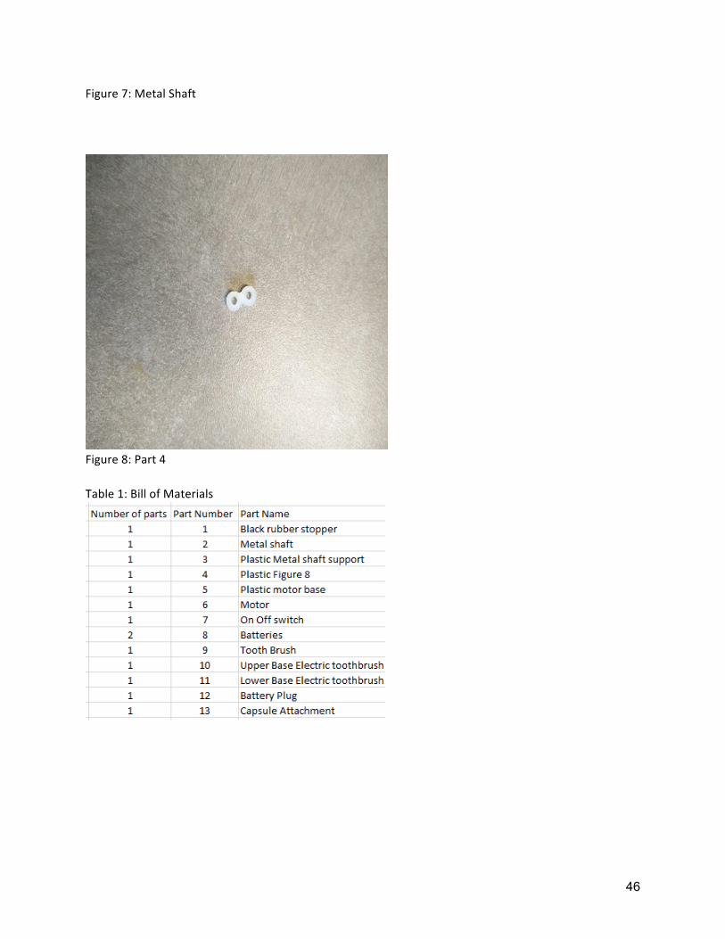
Figure7:MetalShaft
Figure8:Part4Table1:BillofMaterials

47
Appendix D:
48
Figure 1: Toothbrush cad Design
Figure2: Toothbrush cad Design (side view)
49
Figure 3: Toothbrush cad Design (Back view)
50
Figure 4: Cad design assembly
51
Figure 5: Prototype