department of chemical engineering course … · coulson & richardson – chemical engineering...
TRANSCRIPT

DDEEPPAARRTTMM EENNTT OOFF
CCHHEEMM II CCAALL EENNGGII NNEEEERRII NNGG
CCOOUURRSSEE DDII AARRYY (ACADEMIC YEAR 2011-12)
VVII II SSEEMM EESSTTEERR Name : _____________________________________________ USN : _____________________________________________ Semester & Section : _____________________________________________
The Mission
“The mission of our institutions is to provide
world class education in our chosen fields and
prepare people of character, caliber and vision
to build the future world”

DEPT. OF CHEMICAL ENGG. VII SEMESTER COURSE DIARY
MVJCE 2
06CH71- CHEMICAL PROCESS INTEGRATION

DEPT. OF CHEMICAL ENGG. V/VI SEMESTER COURSE DIARY
MVJCE 3
SYLLABUS Hours / Week: 4 I A Marks: 25 Exam Hours: 3 Exam Marks: 100
Part- A UNIT 1 Introduction to process integration: graphics techniques. Overall mass targeting. 06Hrs UNIT 2 Systems of mass exchange network:: graphical approach . direct recycle strategies 7Hrs UNIT 3 Visualization strategies: for development of mass integrated system algebraic approach to targeting direct recycles 6hrs UNIT 4 Algebraic approach: to targeting mass exchange. network recycles strategies using property integration 07 hrs
PART-B UNIT 5 Heat integration: combined heat power integration 6 hrs UNIT 6 Overview of optimization: mathematical approach to direct recycles 7hrs UNIT 7 Mathematical techniques: for synthesis of mass and heat exchange 6 hrs UNIT 8 Mathematical techniques: for mass integration initiatives and application case studies 7 hrs Text Book: 1. Chemical process Design and Integration –Robin smith Wiley 29 chapter 772 pages 2005 2. Pinch analysis and process integration – a user guide on process integration for efficient use of energy, kemp I.C 2nd edition butter worth –Heinnerman 2006 3. Process integration – Mahmoud. m el – Hawalgi elseveier 44 pages 2006

DEPT. OF CHEMICAL ENGG. V/VI SEMESTER COURSE DIARY
MVJCE 4
LESSON PLAN
Hours / Week: 04 I.A. Marks: 25 Total Hours: 52
Sl. No.
Chapter Hour No
Topics to be covered
01
Introduction to Process Integration
01
What is Process Synthesis, process Analysis, Why integration, Categories of process Integration.
02
Overall Mass Targeting
02 Targeting For minimum discharge of waste, 03 Targeting For minimum purchase of material utilities 04 Mass-integration strategies for attaining targets 05 Problems
03
Graphical Techniques for Direct –Recycle strategies
06 Problem statement, source sink mapping diagram and lever arm rules
07 Selection of Sources, Sinks, Recycle Routes 08 Direct-Recycle targets through material recycle pinch
diagram, Design rules for materials pinch diagram 09 Multicomponent source sink mapping Diagram
04
Synthesis of mass exchange network: A Graphical approach
10 Design of individual mass exchangers, Cost optimization of mass exchangers
11 Problem statement for synthesis of mass exchange Networks
12 Mass exchange pinch Diagram 13 Screening multiple external MSAs and constructing the
pinch diagram without process MSAs, Example waste water treatment
05
Visualization Techniques for the development of detailed mass- integration strategies
14 Visualization strategies: Low or no cost strategies 15 Modest changes in process variables and operating
conditions 16 Medium cost strategies and main technology changes,
Problems
06
Algebraic approach to targeting Direct Recycle
17 Algebraic targeting Approach 18 Algebraic targeting procedure 19 Case study: Targeting for acetic acid usage in a vinyl
acetate plant, 20 Problem
07
Algebraic approach to
21 The composition – interval diagram, mass exchange cascade diagram

DEPT. OF CHEMICAL ENGG. V/VI SEMESTER COURSE DIARY
MVJCE 5
targeting mass exchange networks
22 Example of cleaning aqueous wastes, problems
08
Recycle Strategies using Property Integration
23 Property – Based material Recycle pinch Diagram 24 Process modification based on property based pinch
diagram 25 Example of solvent recycle in metal degreasing,
clustering technique for multiple properties 26 Cluster- Based Source sink mapping diagram for
property based Recycle and interception 27 Property based design rules for recycle and interception,
Dealing with multiplicity of cluster –to- property mapping
28 Paper making and fiber Recycle Example, Relationship between Cluster and mass fractions
09
Combined Heat and Power Integration
29 Heat engines 30 Heat pumps 31 Heat Engines and thermal pinch diagram 32 Heat pumps and thermal pinch diagram 33 Cogeneration targeting 34 Problems
10
Overview of Optimization
35 Optimization formulation 36 Mathematical programming 37 Classification of optimization programs 38 Formulation of optimization models 39 Use of 0-1 Binary-integer variable 40 Enumerating multiple solution using integer cuts 41 Modeling discontinuous functions and What –if
Scenarios using integer variables 42 Problems 43 Interaction between direct recycle and the process
11
Mathematical techniques for synthesis of mass and Heat exchange networks
44 Synthesis of HENs
45 Synthesis of MENs
46 Problems
12
Mathematical techniques for mass Integration
47 Mathematical techniques for mass integration 48 Initiatives and applications 49 Case studies 50 Source – interception-Sink representation 51 Incorporation of process model in mass integration 52 Problems

DEPT. OF CHEMICAL ENGG. V/VI SEMESTER COURSE DIARY
MVJCE 6
06CH72 – INSTRUMENTATION & PROCESS CONTROL
SYLLABUS Hours / Week: 4 I A Marks: 25 Exam Hours: 3 Exam Marks: 100
DEPT. OF CHEMICAL ENGG. V/VI SEMESTER COURSE DIARY
MVJCE 7
Part- A UNIT 1 Instrumentation : Fundamentals, static and dynamic characteristics, Indictor and recorders. Pressure Measurements: Gages: bourdon, diaphragm and bellow type gages, vacuum measurements. Temperature Measurements: Bi-metal Thermometers, Resistance thermometers, thermo couples, pyrometers: . 06Hrs UNIT 2 First Order Systems:: Thermometer, level, mixing tanks, stirred tank reactors. (STR) Linearization. I order system in Series Response for various input forcing functions. 06Hrs UNIT 3 Second Order Systems: Characteristics of manometer and damped vibrator. Transfer Functions. Response for various input forcing functions . Response for step input for under damped case-terms associated with it. Transportation Lag 07 hrs UNIT 4 Close Loop Systems: Basic Components .servo and regulator control. Controllers-P I D and On –OFF modes.Contrller Combinations. Final Control Element: Control valves, Actuators, valve positioners. 07 hrs
PART-B UNIT 5 Close Loop response: Block diagram ,Closed loop transfer function, Transient response of servo and regulator control system with various controller modes and their characteristics 07 hrs UNIT 6 Stability: Stability of linear control system.: ROUTH Test..Frequency Response Bode plots
06 hrs UNIT 7 Control System Design by Frequency Response: Bode Criterion. Gain & Phase Margins.. Controller Tuning – Ziegler Nichols, Cohen Coon Methods. 07 hrs UNIT 8 Root Locus: Rules for plotting and problems 06 hrs Text Book: 1. Coughanour & Koppel: Process System Analysis and control, McGraw Hill, New Delhi, II
Edition 1991. Reference Books: 1. Luyben: “Process modeling, simulation & control for Chemical Engineers”, II Edition,
McGraw Hill 1990 2. Coulson & Richardson – Chemical Engineering Vol, III, III Edition, Pengeman Press 3. George Stephanopoules: Chemical Process Control, An Introduction to Theory & Practical,
Prentice Hall, New Delhi, 1998 4. Ceagisokse : “Automatic Process Control for Chemical Engineers”

DEPT. OF CHEMICAL ENGG. V/VI SEMESTER COURSE DIARY
MVJCE 8
LESSON PLAN
Hours / Week: 04 I.A. Marks: 25 Total Hours: 52
Hour.
No Topics to be covered
01 Introduction , Parts of instruments and their functions 02 Static and dynamic characteristics, Indicators & Recorders 03 Pressure gages Bourdon, Diaphragm bellow elements 04 Vacuum measurement: Mcloyd, Pirrani and Ionization gages 05 Temperatutre measurement- Bi metal and resistance thermometers, 06 Laws of thermochemistry& Thermo couples 07 Pyrometers: optical and radiation pyrometers 08 Review of laplace transforms and its important theorems 09 First order systems:- Definition, examples, Derivations of transfer functions for
Thermometer 10 Derivations of transfer functions for (i) level process, (ii) mixing without any
chemical reaction.. 11 Derivations of transfer functions for STR Linerization 12 Derivations of transfer functions for 1st order systems in series 13 Response for step input forcing functions 14 Response for inpluse input forcing functions 15 Response for sinusoidal input forcing functions 16 Problems on 1st order systems 17 Second order systems:-Definition, examples. Derivations of transfer functions for
manometer 18 Derivations of transfer functions for damped vibrator 19 Response for various input forcing functions 20 Response for various input forcing functions 21 Response for step input for under damped case- terms associated with it.
22 Transportation lag 23 Solution t of numerical problems 24 Solution t of numerical problems 25 Closed loop system: basic components. 26 Servo And regulator control 27 Controllers:-defnition a and types 28 Controllers-P I D and On –OFF modes.
29 Controller Combinations. 30 Final Control Element: Control valves, Actuators, valve positioners. 31 Problems 32 Closed loop Response: block diagram 33 Closed loop transfer function, Block diagram reduction 34 Transient response of servo and regulator control system with various controller
modes and their characteristics 35 Transient response of servo and regulator control system with various controller
modes and their characteristics 36 Transient response of servo and regulator control system with various controller

DEPT. OF CHEMICAL ENGG. V/VI SEMESTER COURSE DIARY
MVJCE 9
modes and their characteristics 37 Problems on block diagram reduction 38 Problems on transient response of controllers 39 Stability of linear control systems 40 Routh Test 41 Problems on Routh Test 42 Problems on Routh Test 43 Problems on Routh Test 44 Frequency Response Bode plots 45 Problems for plotting Bode plots 46 Problems for plotting Bode plots 47 Bode criterion, gain & phase margin 48 Problems on , gain & phase margin 49 Problems on , gain & phase margin, bode criterion 50 Controller Tuning – Ziegler Nichols 51 Controller Tuning – Cohen Coon Methods. 52 Problems on Tuning 53 Problems on Tuning 54 Root-Locus Method. 55 Angle & Magnitude Criterion 56 Steps and Rules for plotting R-L diagram/ plots of R.L diagram of a system with
open-loop poles & open loop pole at the origin.. Numerical problem 57 Steps and Rules for plotting R-L diagram/ plots of R.L diagram of a system with
open-loop poles & open loop pole at the origin.. Numerical problem 58 R.L diagram of a system with open-loop poles and open loop zeros with an open
loop pole at the origin. Numerical problem 59 R-L diagram with complex poles/zeros. Numerical problem 60 R-L diagram with complex poles/zeros. Numerical problem 61 Plots of R.L diagram of a system with open-loop poles & open loop pole at the
origin.. Numerical problem 62 Advantages and dis advantages of root –locus metod.

DEPT. OF CHEMICAL ENGG. V/VI SEMESTER COURSE DIARY
MVJCE 10
QUESTION BANK
01 Describe briefly the various types of instruments used in chemical process industries 02 Differentiate between indicating, recording and control instruments 03 What are the essential features of a good measuring instrument? 04 Define and distinguish between (i) static and dynamic error (ii) span and range. 05 What is measurement? How do you classify measuring instruments? 06 Define: (a) Threshold (b) Hysterisis (c) dead zone 07 Describe the different types of instruments, which utilize change of electrical properties
for the measurement of temperature. 08 A large number of thermo couples are connected in parallel, then the generated e m f
will correspond to mean of the temperature of individual junctions. Is this statement true? if ‘yes’ how? If ‘no’ why?
09 With a neat sketch, the construction and working of a radiation pyrometer 10 With a neat sketch, the construction and working of a optical pyrometer 11 Write short note on : Bimetal thermometer 12 Describe with one example each, the principle of liquid, gas expansion and vapour
actuated thermometers. Give the relative advantages and limitations of each type. 13 Suggest most suitable measuring device for the following operations: Temperature range
of 50 to 3000 C, 400 to 12000 C in an oxidizing atmosphere, Measuring and recording the temperature of the contents of a continuous stirred tank reactor
14 Explain the working of thermo couple and describe the compensation methods for variation in the ambient temperature
15 Write a note on: resistance thermometer 16 If several thermocouples were to be installed in a furnace to provide average temperature,
how would you recommend that they be connected? Discuss briefly the installation of a thermocouple in an equipment
17 Classify the pressure measuring instruments used in the industries, based on the principle behind their working
18 Describe the construction and working of McLeod gage stating the range in which it can be used
19 With the help of neat sketches, describe the operation of an un bonded and bonded strain gauge transducers
20 With the help of neat sketches, describe the principle & operation of following pressure measuring instruments (i) thermo couple gage (ii) Ionization gage
21 Explain the use of bellows as pressure transmitter 22 Write short notes on (a) pressure measurement in corrosive fluids (b) Pirrani vacuum
gauge 23 What are ‘Bourdon’ gages? Explain its working with neat diagram indicating the errors
involved in these. Discuss how they can be minimized? 24 Describe the working of a well-type manometer. Derive an expression for the pressure
indicated and compare the same with that of of an inclined tube manometer 25 Write short notes on (i) ring type differential pressure manometer (ii) dead weight Gage.

DEPT. OF CHEMICAL ENGG. V/VI SEMESTER COURSE DIARY
MVJCE 11
26 Suggest a typical flow measuring devices for each of the following cases: (i) measuring
the flow rate and transmitting over 100m (ii) 300 m (iii) 10 km 27 Classify the various types of flow meters and explain one from each category Give their
relative advantages and limitations 28 Suggest suitable flow meter for measuring flow rate of steam in apipe line 29 What are ‘Head meters?’ Explain the one that is used for measuring local, velocities 30 What are ‘area meters? Explain the typical one in detail 31 Explain the working principle of flow measurement using ultra sonic waves 32 Describe the working of Hot wire anemometer and magnetic flow meters 33 When and what situations venturi meter is preferred over orifice meter? 34 Write a note on rotary vane meter 35 How is radioactive method used in level measurements? 36 Explain the measurement of liquid level through electrical conductivity Measurements 37 Explain ‘Bubbler method’ of liquid level measurement 38 How do you measure liquid level if (i) the liquid is corrosive? (ii) The liquid has
suspended particles? Suggest the equipment that is to be used in these two cases Briefly describe their principle of functioning.
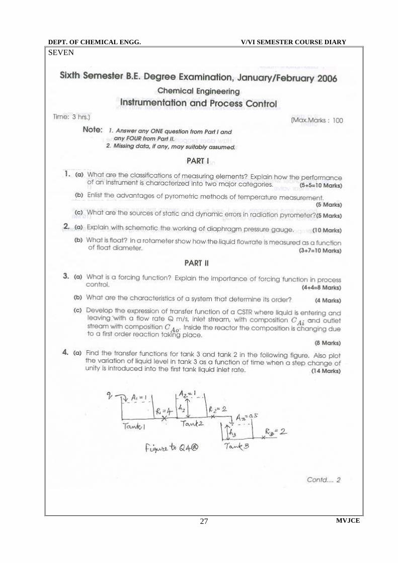
29 Derive the Transfer Function between the liquid levels, H and inlet flow rate, Qi considering a non-linear valve at the exit of the tank. List all the assumptions clearly
30 Derive the Transfer between the thermometer reading and the bath temperature, θo(s)/θi(s) List all the assumptions clearly
31 Derive the Transfer between the exit concentration, C o (s) and the inlet concentration C
i(s) List all the assumptions clearly 32 Derive the Transfer between the exit concentration, C o (s) and the inlet concentration C
i(s) in a tank where first order reaction takes place. List all the assumptions clearly 33 Derive the Transfer between the exit concentration, C o (s) and the inlet concentration C
i(s) in a tank where second order reaction takes place. List all the assumptions clearly 34 Derive the Transfer Function between the liquid level, H and inlet flow rate, Qi
considering a linear valve at the exit of the tank. List all the assumptions clearly 35 Derive the response Y(t) to a first order process for (i)unit step changes(ii) unit ramp
changes (iii)impulse changes(iv) sinusoidal changes in input variable, X(t) List all the assumptions clearly
36 Explain, with suitable examples (i) Resistance (ii) Capacitance (iii) Time constant And (iv) Dead time
37 Calculate the gas capacitance of a 20 m3 pressure vessel containing Air at 20° C 38 A liquid flows in to a tank at a rate of ‘Q’ m3 / min. The tank has three vertical walls and
a fourth one sloping inwards at an angle β to the vertical at the base. The base of tank is square with side, A. The average operating level is ‘ho’ m. (a) Develop a formula for determining the Time Constant τ, (i) for a linear relationship between Q &H (ii) for a non linear relationship between Q/H, with Q = C √H where C is a Constant (b) Calculate the time constant τ, for ho = 1.0 m , A = 0.8 m ‘Q’ = 1.5 m3 / min
DEPT. OF CHEMICAL ENGG. V/VI SEMESTER COURSE DIARY
MVJCE 12
39 A mercury thermometer having a time-constant of 12 sec. is placed in a constant
temperature bath at 100 °C. At time, t=0, the bath temp begins to vary sinusoidally about its mean temp of 100°C with an amplitude of 5 °C. If the frequency of oscillation is (5/π) cycles /min., plot the response of the thermometer reading as a function of time. Also plot, on the same graph sheet the input function. Determine the phase lag in units of time.
40 A thermometer having a time constant of 0.2 min is placed in a constant temp bath and after the thermometer comes to equilibrium with bath temp., the temp of the bath is increased linearly at a rate of 1.2 °/ min. What is the difference between the indicated temp and the bath temp at (a) 0.1 min after the change in bath temp begins (b) What is the maximum deviation between the indicated temp and the bath temp and when does it occur? (c) Plot the forcing function and response function on the same graph. After long enough time, by how many minutes does the response lag the input?
41 Estimate the pneumatic capacitance of an instrument air storage tank with a volume of 1.0 m3 at 2 kgf /cm2 (gage) and 30°C
42 A gas tank is supplied air by compressor at a rate of 0.12 m3 (std) /min. The normal pressure in the tank is 3.0 kgf /cm2 (Ab) and the volume of the tank is 0.3 m3 . The gas is then throttled through a valve to a process down stream. The temp of the surrounding and in the tank may be assumed as constant at 30°C. (i) If the pressure of a downstream process is 2.5 kgf /cm2, what is the time constant of the tank (ii) If the pressure of a downstream process is 1.25 kgf /cm2, what is the time constant of the tank?
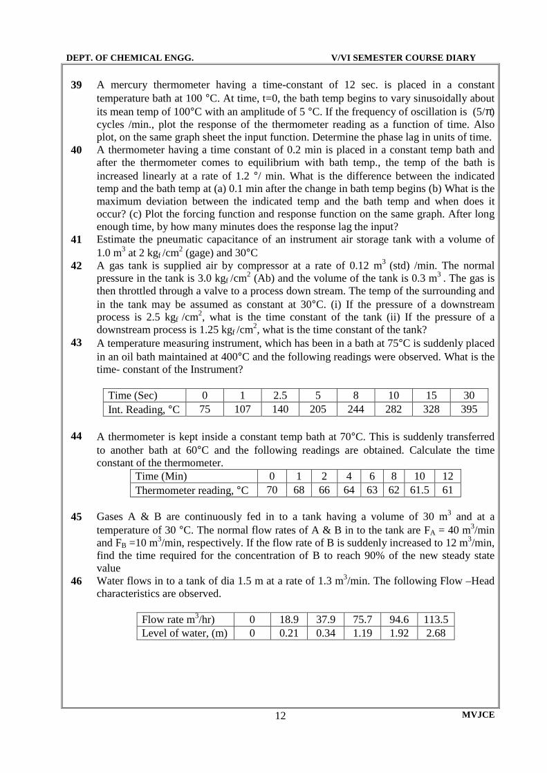
43 A temperature measuring instrument, which has been in a bath at 75°C is suddenly placed in an oil bath maintained at 400°C and the following readings were observed. What is the time- constant of the Instrument?
Time (Sec) 0 1 2.5 5 8 10 15 30 Int. Reading, °C 75 107 140 205 244 282 328 395
44 A thermometer is kept inside a constant temp bath at 70°C. This is suddenly transferred to another bath at 60°C and the following readings are obtained. Calculate the time constant of the thermometer.
Time (Min) 0 1 2 4 6 8 10 12 Thermometer reading, °C 70 68 66 64 63 62 61.5 61
45 Gases A & B are continuously fed in to a tank having a volume of 30 m3 and at a temperature of 30 °C. The normal flow rates of A & B in to the tank are FA = 40 m3/min and FB =10 m3/min, respectively. If the flow rate of B is suddenly increased to 12 m3/min, find the time required for the concentration of B to reach 90% of the new steady state value
46 Water flows in to a tank of dia 1.5 m at a rate of 1.3 m3/min. The following Flow –Head characteristics are observed.
Flow rate m3/hr) 0 18.9 37.9 75.7 94.6 113.5 Level of water, (m) 0 0.21 0.34 1.19 1.92 2.68

DEPT. OF CHEMICAL ENGG. V/VI SEMESTER COURSE DIARY
MVJCE 13
47 Determine the time constant of a Refractory thermocouple sheath having a heat transfer
area of 23.6 x 10⁻³ m2 and mass of 0.2 kg. The specific heat, Cp of the refractory is 0.8 kJ/ (kg)(°C) The furnace is at a temp of 1400 °C and the sheath is at 30 °C. Heat transfer by radiation is only significant. Stefen –Botlzman constant is 5 .667 x 10-8 W/ (m2) K4). The emissivity of the sheath is (i) 1.0 (ii) 0.8.
48 A first order reaction is taking place in a continuous stirred tank reactor (CSTR) with holdup time of 1.5 hr and a specific reaction rate constant of 2 hr-1 . (i) Obtain an expression for the transfer Function between exit and feed concentration. (ii) If the feed concentration changes at a rate of 0.01 kmol/(m3)(hr), what is the dynamic error? (iii) Derive the equation used to solve the problem.
49 Volumetric flow rate over a V notch/weir is given by q = cv √ 2gh5. Calculate the resistance
50 Which of the following five gases causes greatest and least capacitance in the same vessel and at the same temp. (1) Air (2) Ammonia (3) Carbon dioxide (4) Nitrogen (5) steam
51 A stirred tank has a hold up capacity of 0.1 m3 with a flow rate of 5 kg/sec. Heated water passes in to a well-insulated pipe of 0. 02 m2 (cross sectional area) .The temp. is measured at a point 5m down steam by a thermometer with negligible lag. An electric heater provides a constant heat input, 100 kcal/sec. If the inlet temp is 50 °C and cycle continuously with amplitude of ± 2 °C and the period is 1.0 min., determine the steady state behavior of the thermometer reading compared to inlet temp and that in the tank. Show this behavior with the help of neat sketches. List all the assumptions made in solving the problem.
52 A tank having a time constant of 1.0 min and a valve resistance of 0.1 m /(m3)(min) is operated at steady state with an inlet flow rate of 10m3 /min. Then at t = 0 , the flow rate is increased to 100 m3 /min by adding 9 m3 of water to the tank uniformly over a period of 0.1 min. Find an expression for liquid level as function of time. Find out, what would be the liquid level from its steady state value at t = 1.0 min.
53 Derive the transfer function H(s)/Q(s) for the liquid level system of figure (1) when 1. The tank level operates about the steady state value of hs = 1 m 2. The tank level operates about the steady state value of hs = 3 m
The pump removes water at a constant rate of 10 m3/min; this rate is independent of head. The c/s area of the tank is 1.0 m2 and the resistance R = 0.5 min/ m2

DEPT. OF CHEMICAL ENGG. V/VI SEMESTER COURSE DIARY
MVJCE 14
2.4 Q 0
m3/min
1.0
1.0 0.3
54 A tank having a cross sectional area of 2 m2 is operating at steady state with an inlet flow
rate of 2.0 m3/min. The flow head characteristics are shown in Figure 2. 1. Find the transfer function H(s)/Q(s) 2. If the flow to the tank increases from 2.0 to 2.2 m3/min according to a step
change, calculate the level h two minutes after the change occurs.
55 Develop a formula for finding the time constant of the liquid level system shown in figure 2 when the average operating level is h0. The resistance R is linear. The tank has three vertical walls and one, which slopes, at an angle α from the vertical as shown. The distance separating the parallel walls is 1
56 A mixing process may be described as follows: a stream with solute concentration Ci is fed to a
perfectly stirred tank at a constant flow rate at of q. The perfectly mixed product is withdrawn from the tank, also at the flow rate q at the same concentration as the material in the tank, C0. The total volume of solution in the tank is constant at V. Density may be considered to be independent of concentration. A trace of the tank concentration versus time appears as shown in figure 4.
1. Plot on this same figure your best guess of the quantitative behavior of the inlet concentration versus time. Be sure to label the graph with quantitative information regarding times and magnitudes and any other data that will demonstrate your understanding of the situation.
2. Write an equation for Ci as a function of time

DEPT. OF CHEMICAL ENGG. V/VI SEMESTER COURSE DIARY
MVJCE 15
57 What are inter acting and non inter acting processes? 58 What are the different types of classifications of inter acting and non inter acting
processes? Give examples 59 Derive the transfer function for a two tank interacting process relating the level in the
second tank and flow to the first tank, H2(s) /Q1(s) 60 Derive the transfer function between reading of a thermometer in a thermal well and bath
temp, θ3 (s) / θ1 (s) 61 What are damping and damping coefficient? Classify processes based on damping co-
efficient. Give examples. 62 Explain the effect of interaction 63 Derive the transfer function for U tube manometer 64 Obtain the response expressions for II order processes for a unit step change in input (for
all the cases), Y (t) v/s X (t). 65 Describe, with neat sketch, the various terms associated with an under damped process 66 Derive the transfer function for dead time element 67 Mercury filled manometer is to be used to measure the pressure drop across an orifice
meter. The meter will monitor the flow rate of air through the pipe. Specifications call for a decay ratio of 0.3. The max. Pressure differential is such that a liquid column length of 75 cm should suffice. (a) Find the diameter of suitable glass tubing for the U tube. Specific gravity of mercury is 13.6.and viscosity is 1.6 cp (b) The calculations of part (a) having been made you find that only tubing available has a dia of 0.2cm. What should be done to meet the specifications
68 A thermistor used as a thermometer in a gas duct begins to respond immediately when the gas temp is changed from 6.6 to 14.9 °C , at a gas velocity of 6.5 m/sec, 90% net change in temp occurs in 7.1 sec. When the gas velocity is 1.3 m./sec the rise time is 3 sec.(a) What is the dependency of surface heat transfer co efficient between gas and themistor If the gas velocity expressed in the form of h = kUn (b) At the gas velocity of 6.5m/sec How long will it take for the thermistor to be of 99.9 % recovery of a step change in the gas temp.?
69 A step change of magnitude 4.0 is given to a process whose transfer function is Y(s)/ X(s) = [10/ (s2+ 1.6s+4)] Determine (a) the percent overshoot (b) period of oscillation (c) rise time (d) natural frequency (e) ultimate value of Y(t).
70 Two non interacting tanks are operating in series at steady state, when a step change is made in the flow rate to the first tank. The transient response is critically damped and it takes 1 min. for the change in the level of the second tank to reach 50% of the total change. The ratio of the cross sectional area of the tanks is A1/A2 = 2. Calculate I) the ratio R1/R2. ii) the time constant for each tank. iii) the time taken for the change in the level of the first tank to reach 90% of the total change.
71 A proportional controller is used on a process. The proportional band is 10%. It is observed that the valve output undergoes a deviation of 20% of its scale due to disturbance. Determining the corresponding deviation that must have occurred in the controlled variable to cause this change.

DEPT. OF CHEMICAL ENGG. V/VI SEMESTER COURSE DIARY
MVJCE 16
72 The signal to pneumatic PI controller is ε = 0.5 sin ωt. The controller gain KC = 3 and the
reset time τI = 2 minutes. Give the equation for the controller output in consistent units for ω = 10 radians/min. The normal controller is 6 x 10⁴ N/m2. Sketch the output and the input on the same sheet (no need to use graph sheet)
73 A proportional controller is used to control the liquid level within the range of 60 cm to 75 cm. It is found that after adjustments, the controller output pressure changes by 0.1 kg/cm2 for a 2 cm deviation in level with the desired value (set point) held constant. If the variation in the output pressure is 1 kg/cm2 causes the control valve to move from fully open to fully closed. Determine the proportional gain and proportional band.
74 Obtain and sketch the responses of proportional, integral and derivative controllers to a sinusoidal input.
75 An electronic temperature controller has an output range of 0-15 mA and a chart calibration of 50C to 2000C. If the output is 5 mA at 800C when the proportional gain is 0.5 mA/0C. Determine (a) the proportional band (b) the output at (i). 900C ii. At 100 0C
76 A Proportional temperature controller has an output range of 0-20 mA and a chart calibration of 0-200 0C. If the output is 5 mA at 850C when the proportional gain is 1.0 mA/0C (a) Determine the proportional band (b) the output at 120 0C (c) the temperature for an output of 15mA.
77 A Pneumatic PI controller has an output of 0.68 kg/cm2 when the set point and the indicator per point are together. The set point is suddenly moved 1 cm and the following data be obtained
Time (sec) 0- 0+ 20 60 90 Output Kg/cm2 0.68 0.54 0.45 0.34 0.24
Determine the proportional sensitivity in Kg/cm2 and the integral time in seconds 78 The liquid level in a tank of 0.5 m2 cross sectional area is controlled by a two-position
controller with a differential gap of 10 cm at a desired value of 1.5m. The tank has a constant outflow of 1.5 x 10⁻³ m3/sec. The inflow is 1.0 x 10⁻³ m3/sec.when the control valve is completely opened and a bypass flow of 1.0 x 10⁻³ m3/sec. Plot the response against time and determine the effect of (i) a dead time of 3 secs. And )ii). 20% decrease in bypass inflow.
79 Plot on a single graph, the response of each mode to a sine wave function input l= 0.4 sin2t where l is % span. The floating controller has Φ = 2% per minute per % error. The proportional band is 10% and the rate time constant is 4 minutes.
80 The error signal to a controller is changing linearly so that ε = 0.1t, where t is minimum and t is % span. Given a floating controller with f = 2% per minute per % error, proportional band of 10% and rate T of 4 minute. Determine the output signal for each controller (separately) after an elapsed time of i. 30 seconds and ii. 2 minutes.
81 A proportional + reset controller is used to control the temperature of a process. The following data are available
100% measurement input = 80 0 C deviation. 100% controller output = 1 cm value deviation Proportional band = 10% Reset rate = 2 repeats/min.
For a step change of 2 0 C, what is the valve deviation after 2 min

DEPT. OF CHEMICAL ENGG. V/VI SEMESTER COURSE DIARY
MVJCE 17
82 A proportional controller is used to control the temperature within the range of 50 0 C to
100 0 C. The controller is adjusted such that the output pressure varies from 0.2 kg/cm2 (valve fully opened) to 1.0 kg/cm2 (valve fully closed) as the temperature varies from 55 0 C to 59 0 C with the set point held constant. Determine the proportional sensitivity and proportional band
83 A proportional band is used to control temperature within the range of 40 0 C to 80 0 C. The controller is adjusted such that the output pressure varies from 0.2 to 1.0 kg/cm2 (fully open – fully closed) as the measured temperature varies from 580 C to 62 0 C. Determine the proportional sensitivity and proportional band
84 A PID controller is used in a pressure control process with the following data. Full pressure change 10.0 kg/cm2
Full valve travel 2 cm Proportional band 10% Reset rate 1 repeat/min Rate time 1.5 min.
If the pressure changes linearly at a rate of 0.2 kg/cm2 per minute, find the valve deviation at the end of 1 minute. Before the start of pressure change, the valve was at its midpoint and the pressure was 5 kg/cm2
85 Explain the different types of classification of controllers with example 86 What is the different controller combination? What are the relative merits and limitations
of controller combination? 87 What is the different pneumatic controller path? 88 Explain the construction of working of a pneumatic narrow band proportional controller. 89 Explain the construction of working of a pneumatic wide band proportional controller. 90 Explain the construction of working of a proportional reset controller. 91 Explain the construction of working of a proportional + rate controller. 92 Explain the construction of working of a three-mode controller. 93 What are inherent and effective valve characteristics? 94 What are rangability and turndown ratio of control valves? 95 What are the different types of valve – plug and valve seat geometry. Bring out the salient
features of them. 96 What are valve activator and valve positioner? 97 Derive with a neat sketch, the construction and working of a pneumatic valve positioner. 98 What are servomechanism and regulatory problems? 99 Deduce an expression for C (S)/R (S) for a proportional controller as I order process. 100 Deduce an expression for C (S)/U (S) for proportional controller of a I order process. 101 Deduce an expression for C (S)/R (S) for proportional controller of a II order process. 102 Deduce an expression for C (S)/U (S) for proportional controller of a II order process. 103 Deduce an expression for C (S)/R (S) for proportional +Integral of a II order process 104 Show that P+I controller eliminates offset automatically by considering servo problem as
an example. 105 Show that P+I controller eliminates offset automatically by considering regulator problem
as an example.

DEPT. OF CHEMICAL ENGG. V/VI SEMESTER COURSE DIARY
MVJCE 18
106 Show that an integral controller is a pure capacitance changes sinusoidal oscillatory
behavior to a unit step change in set point and hence the controller action is not suitable, by taking appropriate example.
107 Show that the performance and stability is same for both servo and regulator problem. 108 Determine the transfer function C (S)/R (S) for the control system shown in the figure
below
109 A proportional controller is used on a process with time constant of 1 mon and a
measuring lag of 10 secs. What value of proportional gain KC will result in a damping coefficient of G = 0.7 for the two cases of (i) τD = 0 (ii) τD = 3 secs
110 Water at a rate of 0.4 Kg/sec flows through 2 tanks operating in series. The volume of the 2 tanks is 15 and 24 liters respectively. The temperature in the I tank is controlled using a P.D. controller which supplies 50 watt power to the I tank per unit change in the output pressure (KN/m2). There are no lags in the system. Find the offset for the unit step change in inlet water temperature when the controller gain is 40 KN/m2 0 C. The derivative time is 1mon. Also calculate the damping coefficient
111 A process has two major time constants and is controlled with a proportional controller. The transfer functions are given by G1 = 1/(2s+1) and G2 = 1/(0.4s+1). Find the controller gain for the damping coefficient of 0.5
112 A simple feed back controller system consisting of a proportional controller with a gain KC coupled to a process characterized by 2 and 10 secs. The controlled element is sensed by an element with a time constant of 10 secs. and a time delay of 4 secs. And the reference signal is fed to the controller-summing junction through a first order pneumatic transmitter with a time constant of 1 sec.
i. Sketch the block diagram for this system ii. Write the transfer function relating the controlled variable ‘C’ to the reference ‘R’ iii. Write the transfer function relating sensor output ‘B/ to the reference ‘R’
113 A simple feed back controller system consisting of a proportional + integral controller coupled to a proceass characterized by two time constants of 3 and 6 secs. The controlled element is sensed by an element with a time constant of 10 secs. and a time delay of 4 secs. and the reference signal is fed to the controller summing junction through a first order pneumatic transmitter with a time constant of 1 sec.
i. Sketch the block diagram for this system ii. Write the transfer function relating the controlled variable ‘C’ to the reference ‘R’ iii. Write the transfer function relating sensor output ‘B/ to the reference ‘R’

DEPT. OF CHEMICAL ENGG. V/VI SEMESTER COURSE DIARY
MVJCE 19
114 A closed loop control system has time constant of 1 and 2 minute respectively. A
proportional controller and unity feed back element and unity steady state gain. Obtain the response to a unit step change in the set point at a controller gain that gives a damping coefficient of 0.8. Would a higher or a lower gain be advantageous for the system. How & Why?
115 A simple feed back control system consists of a proportional controller with a gain KC coupled to a proceass characterized by two time constants of 2 and 10 secs. And a steady state gain of 10 secs. The controlled variable is sensed by an element with a time constant of 5 secs. and a dead time of 1 sec.
i. Sketch the block diagram for this system ii. Write the transfer function relating the controlled variable ‘C’ to the reference ‘R’
116 The major elements of a closed loop control system are having the following transfer function
GP(s) = (1.5) / ((s+1)(2s+1)) GC(s) = KC
Transfer functions for the rest of the components in the loop are unity. All time constants are in minutes. Determine the transient response for unit impulse input in set point at a controller gain that gives critically damped system
117 A unit feed back control system has two processes each having a time constant of one minute under a proptional controller working in series. Obtain the response to a unit step change in set point at a controller gain that gives a damping coefficient of 0.8 for the case of
a) Non interacting tank in series b) Interacting tanks in series
Would a higher or a lower gain is advantages? How and Why 118 Determine the overall transfer function C/R of a control system having the following
transfer functions for its elements in a servo type negative feed back system Controller GC = KC Final control element Gv = Kv Process Gp = Kp/ (τ1s+1) (τ2s+1) Measuring element H = 1/(τMs+1)
Controlled variable is C and set point is R 119 A unity feedback system is characterized by an open loop transfer function Gp = Kp/
s(s+10) and proportional controller with proportional gain is Kc. Determine the proportional gain Kc so that the closed loop will have a damping coefficient of 0.5. Determine the settling peak overshoot and time to peak overshoot (rise time) for a unit step input (Kp = 1)
120 The major elements of a closed loop control system are having the following transfer function
GP(s) = (1.5) / ((s+1)(2s+1)) GC(s) = KC
Transfer functions for the rest of the components in the loop are unity. All time constants are in minutes. Determine the transient response for unit impulse input in set point at a controller gain that gives critically damped system

DEPT. OF CHEMICAL ENGG. V/VI SEMESTER COURSE DIARY
MVJCE 20
121 A unit feed back control system has two processes each having a time constant of one
minute under a proportional controller working in series. Obtain the response to a unit step change in set point at a controller gain that gives a damping coefficient of 0.8 for the case of: i. Non interacting tank in series ii. Interacting tanks in series
Would a higher or a lower gain be advantages? How and Why 122 A unity feedback system is characterized by an open loop transfer function GC = KP/
s(s+10) and proportional controller with proportional gain is Kc. Determine the proportional gain Kc so that the closed loop will have a damping coefficient of 0.5. Determine the settling peak overshoot and time to peak overshoot (rise time) for a unit step input (KP = 1)
123 A proportional Derivative controller is used in a system with a process and a first order-measuring lag. Find expression for the characteristics time τC and damping factor for closed loop system. If the process time constant is 1 min and measuring time constant of 10 sec. Find the gain that gives G = 0.5 for the two cases of τD = 0 sec, τD = 3 sec
124 A closed loop system has time constant of 1 min and 10 min and a proportional controller. Obtain response of a unit ramp change that gives a damping coefficient of 0.3 would a higher or lower gain the advantageous? How? And why?
125 A block diagram of a control system is presented in the fig below
i. What value of proportional gain KC will result in critically damped behavior ii. If the controller gain of part (a) is used what ‘OFFSET’ will result for an unit step
change inset point ‘R’ iii. For unit step change in set point ‘R’ what must be the controller gain if the offset is
10% 126 A heat exchange is used to preheat a process fluid passing through tube side by means of
shell side hot oil. The exit fluid temperature Tfe is controlled by means of automatic manipulation of the pressure on the diaphragm of a pneumatic valve in the oil line. The temperature of inlet oil Toi is a major distribution to the process. Experimental data indicate that the T F relating to Tfe and Toi is
Tfe (s)/ Toi (s) = 1/(50s2+1s+0.5) and F, the flow rate of oil is Tfe(s) /F(s) = 20/(s+1)(50s2+12s+0.5)
a) Sketch pictorial and a block diagram for control loop of the heat exchange including a proportional controller and a fast acting-measuring device. The controller uses air pressure for input and output signal. The gain of the control valve is 30 lt/min per psi and its dynamics is negligible. Label all the variables and transfer function
b) Find the max valve of proportional gain of controller that can be used
DEPT. OF CHEMICAL ENGG. V/VI SEMESTER COURSE DIARY
MVJCE 21
127 A unity feed back control system has a process and a controller whose transfer functions
are GP = 1/(s2+2s+6); GC = KC (1+0.5s) it is desired that the offset in the controlled variable should not exceed 0.091 for a unit step change in set point What is the damping coefficient for this condition
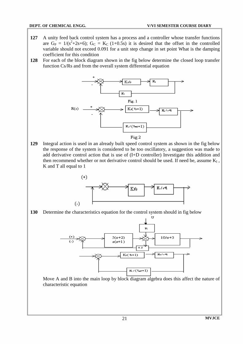
128 For each of the block diagram shown in the fig below determine the closed loop transfer function Cs/Rs and from the overall system differential equation
129 Integral action is used in an already built speed control system as shown in the fig below
the response of the system is considered to be too oscillatory, a suggestion was made to add derivative control action that is use of (I+D controller) Investigate this addition and then recommend whether or not derivative control should be used. If need be, assume KI , K and T all equal to 1
130 Determine the characteristics equation for the control system should in fig below
Move A and B into the main loop by block diagram algebra does this affect the nature of characteristic equation
DEPT. OF CHEMICAL ENGG. V/VI SEMESTER COURSE DIARY
MVJCE 22
131 The major elements of a closed loop control system are given below. The time constants
are min. Calculate (obtain) the transient response for unit step change in load at a controller gain that gives critical damp system GP (s) = 1.0/((2s+1)(10s+1)) Transfer function of load change = 1.0/(10s+1) GC(s) = Kc All other transfer functions are unity
132 A liquid level system consists of two non-interacting tanks in series the first tank has a cross sectional area of 0.2m2 the flow head characteristics for the tank can be given by the equation q = 2h. The second tank has a cross sectional area of 0.1 m2 and outflow is by a constant displacement pump delivery 2m3 /sec. The (outflow of tank is 2m3 /sec and the level is 1m) level in the second tank is controlled by pneumatic PD controller and a valve with linear characteristics delivering 0.01 m3 /sec per KN/m2 controller output pressure, to the first tank. The first tank has an independent inflow varying fro 0.75 to 1.25 m3 /sec draw the block diagram for this control system with appropriate numerical transfer functions and various quantities of signal
133 A process of two first order elements with time constant of 10 min each is connected to a measuring element with a 4min time constant and one min time delay. The process is controlled by a proportional controller .The Kc of which is 5 i. Draw the block diagram with appropriate numerical transfer functions ii. Obtain C(s)/R(s) for the system
134 Define stability 135 Explain Routh Hurwitz stability criteria 136 Explain step by step procedure for plotting root locus diagram 137 What is Bode plot. Explain the construction of the Bode plot 138 Explain Bode’s stability criteria 139 What is gain margin and phase margin 140 The characteristic equation s4+2s3+6s2+8s+1=0 find the roots of the equation and discuss
the stability of the system 141 The characteristic equation s3+4s2+5s+10=0 find the roots of the equation and discuss the
stability of the system 142 Find the root of the equation: G(s) = 10/s(s-1)(2s+3) 143 The characteristic equation is s4 + s3+2s2+2s+3=0 find the roots of the equation and
discuss the stability of the system 144 Determine the range of K for stability of a unity feed back control system whose open
loop transfer function is G(s) = K/s(s+1)(s+2) 145 A four-stage process has time constant of 1,2,3 and 4 minutes with a gain of 5. Is this
system stable if proportional controller with gain of KC = 2 is used 146 The open loop transfer function a unity feed back control system is given by G(s) =
K/(s+4)(s+2)( s2+6s+25) determine the value of K which gives sustained oscillation in the closed loop system. What are the corresponding oscillation frequencies (use RH method)?
147 Draw the Root Locus Diagram for the control system whose open loop transfer Functions
are: )4()2( ++
=sss
KGH
148
)8()6( ++=
sss
KGH

DEPT. OF CHEMICAL ENGG. V/VI SEMESTER COURSE DIARY
MVJCE 23
149
)9(2 +=
ss
KGH
150
)4()3()1( +++=
ssss
KGH
151
)1010()1010()14(
)8(
jsjss
sKGH
−+++++=
152
)2()2()1( jsjss
KGH
++−++=
153
)3()3()1(
)2(
jsjss
sKGH
−+++++=
154 Draw the Root Locus Diagram for the control system whose closed loop transfer functions are:
a. 1 + GH = 0 = s(s+3)(s2+2s+2)+K = 0 b. 1 + GH = 0 = s(s+2) +K(s+4) = 0 c. 1 + GH = 0 = s(s2+2s+2)+K = 0 d. s2 (s+8) + K = 0 e. s3 + 8s3 + Ks + K = 0 f. (S+2)2 + K = 0
155 A unity feed back control system has an open loop transfer function as
)0053.01()025.01( ++=
s
KGH
Sketch the root locus diagram for K > 0. Determine the value of K for stability. Determine the value of K when the system has two equal characteristic roots
156 A unity feed back control system has an open loop transfer function as
)6()5()22(
)2(
+++++=
ssssss
sKGH
Sketch the root locus diagram for K > 0. Determine the value of K for stability. Determine the value of K when the system has two equal characteristic roots
157 A feed back control system has an open loop transfer function as
)22()3( 2 +++=
ssss
KGH
Find the root locus diagram as K varies from 0 to ∞. Determine the value of K for stability. Determine the value of K when the system has two equal characteristic roots
158 A unity feed back control system has an open loop transfer function as 3)2( +
=ss
KGH
Sketch the root locus diagram and determine the following (i). Value of K for which root locus crosses the imaginary axis (ii) Frequency for sustained oscillation

DEPT. OF CHEMICAL ENGG. V/VI SEMESTER COURSE DIARY
MVJCE 24
159 The characteristics equation of a feed back control system is: s4 + 3s3 + 12s2 + (k-16) s + K = 0 160 Sketch the root locus diagram for 0 ≤ K ≤ ∞ and show that the system is conditionally
stable (i.e. stable for only a range of k) Determine the range of gain k for which the system is stable
161
)2()1()(
++=
sss
KsG
i. Sketch the root locus for 0 ≤ K ≤ ∞ ii. Determine the range of K for which the system is stable iii. Determine the value of K when the system is critically damped
162
)5()1( ++=
sss
KGH
Sketch the root locus diagram for the system. Indicate the crossing points of the loci on the imaginary axis and corresponding values of K and the frequency of oscillation. Sketch the root locus diagram for the system. Determine the stability of the system
163 A unity feed back control system has an open loop transfer function as
)1(
)1(
−+=
ss
sKGH
)5()1( ++=
sss
KGH
Sketch the root locus diagram with K as variable parameter. Is the system stable for all values of K. If not determine the value of K for stable system operation and determine the following
164 Sketch the Bode diagram for the following transfer functions: i. (1+s)2 ii. s/(2s+1) iii. (1-0.5s)/(1+0.5s)
165 Sketch the gain vs frequency asymptotic Bode diagram for each of the following transfer function:
i. 100/(10s+1)(s+1) ii. 10s/(s+1)(0.1s+1) 2
iii. (s+1)/(0.1s+1)(10s+1) iv. (s-1)/(0.1s+1)(10s+1) v. (10s+1) 2 vi. (10+s) 2
166 Sketch the Bode diagram of: A second order system with a natural frequency of 1c/s and a damping factor of 2, A PID controller with a interal time of 2 min a derivative time of 0.4 mins and a proptional gain of 4 units

DEPT. OF CHEMICAL ENGG. V/VI SEMESTER COURSE DIARY
MVJCE 25
167 Sketch the Bode open loop frequency response diagram for the following transfer
functions and calculate the gain and phase angle for ω = 10 rad/min in each case (is in min-1):
i. 50/(10s+1)(2s+1) ii. 10s/(0.2s+1) 2 (s+1) iii. (s+1)/(10s+1)(3s+1) iv. (s-1)/(10s+1)(2s+1) v. (1+s)2
vi. (1-0.5s)/(1+0.5s) 168 Draw the Bode diagram for a second order system whose dampling coefficient are
0,0.5,0.7,1.0 and 2.0 Explain the change in trends of these plots 169 Draw the Bode diagram of the following transfer functions: G(s) = e-0.5s / 1+s 170 Draw the Bode diagram for: G(s) = 10(s+3)/s(s+2)(s2+s+2) 171 Plot Bode diagram for the transfer function: G(s) = 10(s+10)/s(s+2)(s+5) 172 Plot Bode diagram for the open loop transfer function of the control system
G(s) = 10(0.5s+1) e-s/10 /(s+1)2(0.1s+1)
173 Plot the overall Bode diagram for a level control system of two non interacting vessels
with a inlet control valve approximating to first order element. The valve has a time constant of 15s and one percent change valve position changes the inlet flow by 0.5% of the average value. The first tank has a time constant of 30s and10% increase in flow rises the level by one meter. The second tank has a time constant of 60s and the level increases by 0.8 mt for an increase in level of 1 mt in the first tank
174 Plot the open loop Bode diagram for a system with a first order lag of 10sec and 30sec and time delay of 3sec Determine the value of KC to give 300 phase margin. What is the gain margin at this value of KC
���� Kc ���� 16
2
+s ����
12
1
+s ���� Kc ����
175 Obtain the phase margin and gain margin of system whose open loop transfer function is
)5()1()()(
++=
sss
KsHsG for the two cases K = 10 & K = 100
176 Sketch the Bode plot for a process and measuring element with an overall transfer
function 2
55.0
)12( +
−
s
e and determine the maximum value of KC for a proportional controller
(s in min-1)

DEPT. OF CHEMICAL ENGG. V/VI SEMESTER COURSE DIARY
MVJCE 26
177 Plot the open loop Bode diagram for the control loop and determine the phase and gain
margin
178 A temperature control system has a process time constants of 20 mins. And 5 mins. The
control valve and the thermometer bulb have time constants of 10 secs. A 1 psi change in controller output changes the controlled flow 25 gpm from the normal value of 200 gpm. The process temperature is 175 0 F for 200 gpm and 174 0 F for 210 gpm. A bulb with a range of 80 0 F is used.
i. Calculate the overall gain ii. Calculate the maximum controller gain
179 For the transfer function
)1()110(
100
++ ss Sketch gain Vs. frequency asymptotic Bode
diagram. Find also the actual gain and the phase angel at ω = 10 180 139.Consider the unity feed back control system whose open loop transfer function is
2
)1()(
s
assG
+= , Determine the value of ‘a’ so that the phase margin = 45 0
181 Plot the Bode diagram for an experimental test on a process which gives the following results.
Frequency Rad/min 2.5 4 6.3 10 15.8 A.R. 0.87 0.72 0.57 0.35 0.14 Phase Lag 30 60 100 150 200
DEPT. OF CHEMICAL ENGG. V/VI SEMESTER COURSE DIARY
MVJCE 27
SEVEN

DEPT. OF CHEMICAL ENGG. V/VI SEMESTER COURSE DIARY
MVJCE 28

DEPT. OF CHEMICAL ENGG. VII/VIII SEMESTER COURSE DIARY
MVJCE 29

DEPT. OF CHEMICAL ENGG. VII/VIII SEMESTER COURSE DIARY
MVJCE 30

DEPT. OF CHEMICAL ENGG. VII/VIII SEMESTER COURSE DIARY
MVJCE 31
06CH73 – COMPUTER APPLICATIONS & MODELING

DEPT. OF CHEMICAL ENGG. VII/VIII SEMESTER COURSE DIARY
MVJCE 32
SYLLABUS Hours / Week: 4 I A Marks: 25 Exam Hours: 3 Exam Marks: 100
ALGORITHM AND PROGRAM FOR CASES OF UNIT I TO VI PART A
UNIT 1 Numerical Techniques:
1. Simultaneous linear algebraic equation- Gauss Jordan (material balance for distillation and mixing),
2. Non-linear algebraic equation-Newton Raphson (Specific volume of binary mixture using real gas equations)
3. Ordinary Differential Equation- R-K Method (dCA/dt= K Ca2)
4. Numerical Integration-Simpson’s 1/3 Rule (Batch Reactor to find time) 5. Curve Fitting- Least Square (Arrhenius) 07 Hrs
UNIT 2 Applications:
6. P – X,Y and T – X, Y evaluation 7. Calculation of Bubble Point and Dew Point for Ideal multi-component system 07Hrs
UNIT 3 Flash Vapourization 8.For multicomponent system 9.Design of Adiabatic Batch Reactor 06Hrs UNIT 4 10. Design of Adiabatic Plug flow Reactor 11. Design of Adiabatic CSTR and Combinations 06Hrs
PART B UNIT 5 Design
12.Double pipe Heat Exchanger (Area, Length and Pressure drop) 13.Shell Tube Heat Exchanger (Area, Number of tubes, Pressure drop) 06Hrs
UNIT6 Absorbtion &Distillation Columns
14.Calculations for plate and packed columns 06Hrs UNIT 7 Modeling: Models and model building, principles of model formulations, precautions in model building, Fundamental laws: Review of shell balance approach, continuity equation, energy equation, equation of motion, transport equation of state equilibrium and Kinetics, classification of mathematical models. 07 Hrs UNIT 8
Mathematical Modeling and Solutions to the Following: 1.Basic tank model -Level V/s time 1. Batch Distillation -Vapor composition with time 2. Three CSTR in series 07Hrs

DEPT. OF CHEMICAL ENGG. VII/VIII SEMESTER COURSE DIARY
MVJCE 33
Text Books: 1. M. Shanthakumar – “Computer based Numerical Analysis”, KPS publicher, First edn, 1987. 2. Introduction to Chemical Engineering and Computer Calculations – Myers, A.L. and Seider. W.D. 3. William. L. Luyben – “Process Modeling simulation and control for chemical engineers” 2nd Edn., Mc Graw Hill, 1990. Reference Books: 1. H. Scott Fogler, “Elements of Chemical Reaction Engineering”, 2nd Ed., Prentice Hall, 2001. 2. Smith J.M. and H.C. Vanness – “Introduction to Chemical Engg. Thermodynamics” – 5th Edition, MGH, 1996.

DEPT. OF CHEMICAL ENGG. VII/VIII SEMESTER COURSE DIARY
MVJCE 34
LESSON PLAN Hours / Week: 04 I.A. Marks: 25 Total Hours: 52
Chapter Hour No
Description
N U M E R I C A L
T E C H N I Q U E S
1 Introduction to C program: Structure of C, types of data base, input & Output statements.
2 Introduction to C program: Input & output statements, Arrays, general programs.
3 Algorithm: To find a specific volume of binary mixture by using Newton Raphson method.
4 C program: To find a specific volume of binary mixture by using Newton Raphson method.
5 Algorithm & C program: To fit a curve by using least square method for Arrehenius equation.
6 Algorithm & C program: To find the residence time for a batch reactor using simpson 1/3rd rule
7 Algorithm & C program: To solve ordinary differential equation using Runge Kutta method.
8 Algorithm: To solve material balance equation of mixing using Guass Jordan method.
9 C Program: To solve material balance equation of mixing using Guass Jordan method.
A P P L I C A T I O N S
10 Algorithm & C program: To evaluate P – X, Y data 11 Algorithm & C program: To evaluate T – X, Y data 12 Algorithm: To evaluate bubble point temperature for ideal multi
component system. 13 C Program: To evaluate bubble point temperature for ideal multi
component system. 14 Algorithm: To evaluate dew point temperature for ideal multi
component system. 15 C Program: To evaluate dew point temperature for ideal multi
component system. 16 Algorithm: To evaluate flash vaporization for ideal multi component
system. 17 C Program: To evaluate flash vaporization for ideal multi component
system. 18 Algorithm: To evaluate adiabatic batch reactor. 19 C Program: To evaluate adiabatic batch reactor. 20 Algorithm: To evaluate adiabatic CSTR. 21 C Program: To evaluate adiabatic CSTR.
DEPT. OF CHEMICAL ENGG. VII/VIII SEMESTER COURSE DIARY
MVJCE 35
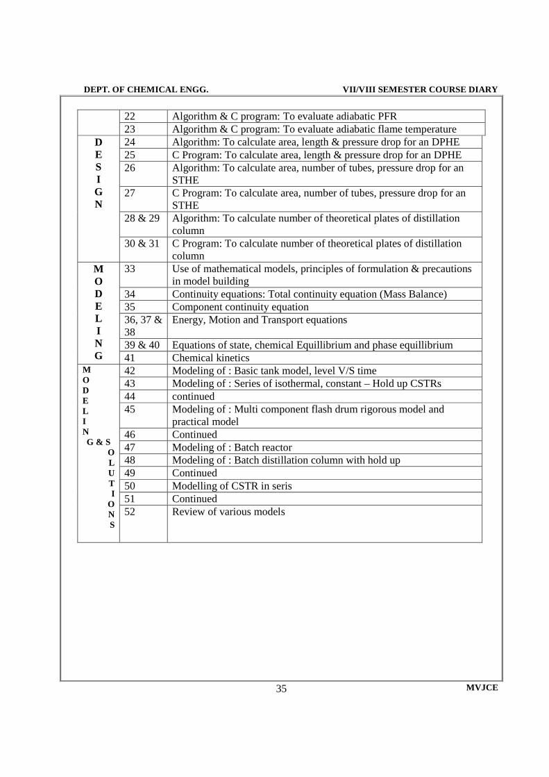
22 Algorithm & C program: To evaluate adiabatic PFR
23 Algorithm & C program: To evaluate adiabatic flame temperature D E S I G N
24 Algorithm: To calculate area, length & pressure drop for an DPHE 25 C Program: To calculate area, length & pressure drop for an DPHE 26 Algorithm: To calculate area, number of tubes, pressure drop for an
STHE 27 C Program: To calculate area, number of tubes, pressure drop for an
STHE 28 & 29 Algorithm: To calculate number of theoretical plates of distillation
column 30 & 31 C Program: To calculate number of theoretical plates of distillation
column M O D E L I N G
33 Use of mathematical models, principles of formulation & precautions in model building
34 Continuity equations: Total continuity equation (Mass Balance) 35 Component continuity equation 36, 37 & 38
Energy, Motion and Transport equations
39 & 40 Equations of state, chemical Equillibrium and phase equillibrium 41 Chemical kinetics
M O D E L I N G & S
O L U T I
O N S
42 Modeling of : Basic tank model, level V/S time 43 Modeling of : Series of isothermal, constant – Hold up CSTRs 44 continued 45 Modeling of : Multi component flash drum rigorous model and
practical model 46 Continued 47 Modeling of : Batch reactor 48 Modeling of : Batch distillation column with hold up 49 Continued 50 Modelling of CSTR in seris 51 Continued 52 Review of various models

DEPT. OF CHEMICAL ENGG. VII/VIII SEMESTER COURSE DIARY
MVJCE 36
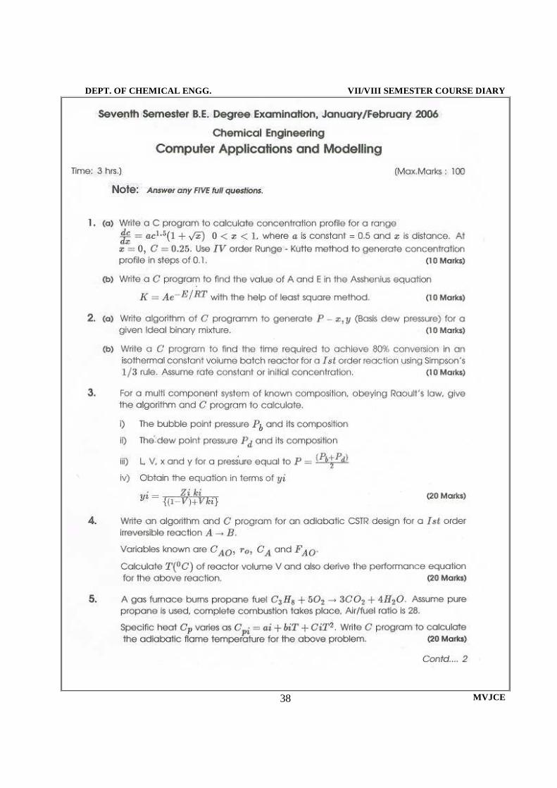
QUESTION BANK 1. Write a ‘C’ program to pick negative, zero and positive numbers from a given set of N numbers using arithmetic IF. Using the format statement print the answer 2. Write a ‘C’ program which will evaluate the function for x=0.5 to 3 varying in steps of 0.5 and tabulate the results: f = 1 + x2/2 + x4 / 4 – 0.5 sin2x + (4 – x2) 1/2 3. Write ‘C’ program to find the root of the equation: f(x) = x3 – x – 1 = 0, by bisection method
4. Write ‘C’ program to find the root of the equation: f(x) = x3 + x2 – 1 = 0 by Newton – Raphson method 5. Write ‘C’ program to integrate Area = ∫ ƒ(x) dx from the given Values
X 7.47 7.48 7.49 7.50 7.51 7.52 ƒ(x) 1.93 1.95 1.98 2.01 2.03 2.06
With h = 0.001 using trapezoidal rule 1. Evaluate I = ∫ 1/ 1 + x. The values of x and y are tabulated below:
X 0 0.5 1.0 Y 1.000 0.667 0.5
h = 0.05 and write a ‘C’ program to solve the above problem using Simpson’s 1/3rd rule.
2. Write a ‘C’ program to solve the simultaneous equation using Gaussian Elimination method and Gauss Jordan method. 10x + 2y + z = 9 2x + 20y – 2z = -44; -2x + 3y + 10z = 22 3. Write a ‘C’ program to Solve the ordinary differential equation: dy/dx = x2/y2 + 1 using Euler’s method 4. Write a ‘C’ program to Solve the ordinary differential equation dy/dx = y – x where y (0) = 2. Find y (0.1) and y(0.2) using Runge-Kutta method 5. Write a ‘C’ program to Solve the ordinary differential equation: dy/dx = y2 – x2 where y(0) = 2. Find y (0.1) and y(0.2) using Runge-Kutta method 6. Molar volume of benzene vapour at 563.15 0K is given as a function of pressure. Assume that the P-V data obeys the virial equation of state terminated after the third virial coefficient. Write a ‘C’ program to find the second and third virial coefficients. Hint: Method of least squares can be used. 7. Assuming that Raoult’s law is applicable for the system acetone (1)/acetonitrile (2) /nitromethane (3), write a ‘C’ program to calculate bubble pressure, dew pressure, bubble temperature and dew temperature.
7.52
7.47
0
1

DEPT. OF CHEMICAL ENGG. VII/VIII SEMESTER COURSE DIARY
MVJCE 37
8. Calculate the molar volume of propane at 440 K and 150 atm. Using Pitzer’s theory. The vapour pressure of propane is given by Antonine Equation lnP = A – B/T + C where A = 15.7260, B = 1872.46 & C = -25.16. TC = 370 K, PC = 42 atm. 9. Write a ‘C’ program to find the molar volume of a gas using Vanderwalls/s equation
10. What is principle of corresponding states? Explain
11. What is UNIFAC method? Explain its significance
12. A gas furnace burns propane fuel, the chemical reaction for complete combustion is C3H8 + SO2 = 3CO2 + 4H2O, This is a fast and irreversible reaction. Solve for the composition and flow rate. 13. Assume that the fuel is pure propane and that air is 21% oxygen and 79% nitrogen. 13. Hot soap is chilled on a roller and scraped continuously from the roller onto a moving conveyor belt (stream 1), which carries the soap into a dryer. The entering soap contains 25% water by weight. It is desired to reduce the water content to 15% water by weight (stream 3) and to produce 1200 kg/hr of dried soap chips. The entering air contains 0.3-mol% water vapour. The air/wet chip ratio = 3 (1) Set the material balance equation and find the number of design variables. (2) Calculate the unknown flow rates and composition. 14. Give the algorithm and write a ‘C’ program for an adiabatic, non-isothermal batch reactor, in which a first order liquid phase irreversible reaction is taking place. The residence time required for a specified conversion should be the output result of the program. 15. The feed to an ammonia reactor contains nitrogen, recycled ammonia and inert impurities (methane and argon). The reaction is N2 + 3H2 = 2 NH3. Nitrogen and hydrogen in the feed are in the stoichiometric proportion 1:3. Determine the flow rate and composition of the product stream in terms of the feed stream variables. Take suitable design variable. 16. The process shown in the flow diagram converts feed stream (1) of n-butane to isobutene in a catalytic reactor. The conversion to isobutene is incomplete and the products from the reactor stream (2) are separated by distillation into isobutene (stream 3) and unreacted n-butane (stream 4). The isobutene is more volatile than n-butane and is obtained from the distillation tower as the distillate. Use CSTR for butane isomerization. Determine all process flow rates and mole fractions. Take suitable design variables. 17. Write a program to design a double pipe heat exchanger. Write down the algorithm and explain the design procedure in detail. 18. Write a program to design a single effect evaporator. Write down the algorithm and explain the design procedure in detail. 19. Write a program to design a shell & tube heat exchanger. Write down the algorithm and explain the design procedure in detail. 20. Write a program to determine the number of ideal stages required in a binary distillation column by McCabe – Thiele method. Write down the algorithm and explain the design procedure in detail.
DEPT. OF CHEMICAL ENGG. VII/VIII SEMESTER COURSE DIARY
MVJCE 38

DEPT. OF CHEMICAL ENGG. VII/VIII SEMESTER COURSE DIARY
MVJCE 39

DEPT. OF CHEMICAL ENGG. VII/VIII SEMESTER COURSE DIARY
MVJCE 40
06CH74 – BIO CHEMICAL ENGINEERING

DEPT. OF CHEMICAL ENGG. VII/VIII SEMESTER COURSE DIARY
MVJCE 41
SYLLABUS
Hours / Week: 4 I A Marks: 25 Exam Hours: 3 Exam Marks: 100
PART-A
UNIT-1 INTRODUCTION: Bioprocess engineering and technology Role of a chemical engineer in bioprocess industry An introcduction to basic biological sciences. Microbiology structure of cells Prockaryotes and eukaryotes classification of microorganisms taxanomym environmental industrial microbiology 6hrs UNIT-1I Biochemistry: Chemicals of life lipids sugars, polysaccharides, amino acids, and protein Vitamines Biopolymers nucleic acids RNA, DNA and their derivatives.(structure biological function and importance for life only to be studied.) 7hrs UNIT-1II Enzyme and Proteinss: details structure of proteins and enzymes functions methods of production and purification of enzymes Nomenclature and classification of enzymes, kinetic of enzymes action Michaelis menten rate equation derivation 6hrs UNIT-1V Kinetics of enzymes action: Reversible enzymes two substrate multicomlex enzymes kinetics(derivation of rate equation)experimental of rate parameter batch & continuous flow experiment Lineweaver burk Eadie Hofstee and hanes woolf plots Batch kinetics (integral and differntial methods) 7hrs
PART-B. UNIT-V Enzyme Inhibition: effect of inhibiton (competitive, non competitive substrateand product inhibition) Temperature and pH on the rates enzymes catalyzed reactions determination of kinetics parameters for various types of inhibition Dixon method enzyme immobilization uses methods of enzymes immobilization. 7hrs UNIT-VI Fermentation technology: Ideal bioreactors, A review of batch and continuous flow reactors for bio kinetics measurements microbiology reactors operation and maintenance of typical aseptic fermentation process.formulataion of medium ,sources of nutrients, alternate bioreactor configuration.introduction to sterilization of bioprocess equipments. 7hrs UNIT-VII Growth Kinetics of microganisms: Transient growth kinetics (different phase of batch cultivation) Quantification of growth kinetics substrate limited growth ,models with growth inhibitor, logistic equation ,filaments cell growth model, continuous culture optimum dilution rate in ideal chemostat introduction to fed-batch reactors. 6hrs

DEPT. OF CHEMICAL ENGG. VII/VIII SEMESTER COURSE DIARY
MVJCE 42
UNIT-VIII Downstream processes: strategies and steps involved in product purificatiaon methods of cell disruption, - Filtration, centrifugation, sedimentation chromatography freeze drying/lyophilization menbrane separation technology reverse osmosis ultra filtration micro filtation dialyusis 6hrs Text Books: 1. Biochemical Engineering Fundamentals- Bailey & Ollis, II Edition, McGraw Hill, 1986 2. Microbiology Concepts & Application:- McGraw Hill, 1993 by Pelczar Reference Books: 1. Biochemical Engineering: Aiba, Academic Press, 1965 2. Industrial Microbiology- Casida 3. Biochemistry: - Lehninzer 4. Chemical Engineering III Edition, Coulson & Richardson
DEPT. OF CHEMICAL ENGG. VII/VIII SEMESTER COURSE DIARY
MVJCE 43
LESSON PLAN
Hours / Week: 04 I.A. Marks: 25 Total Hours: 52
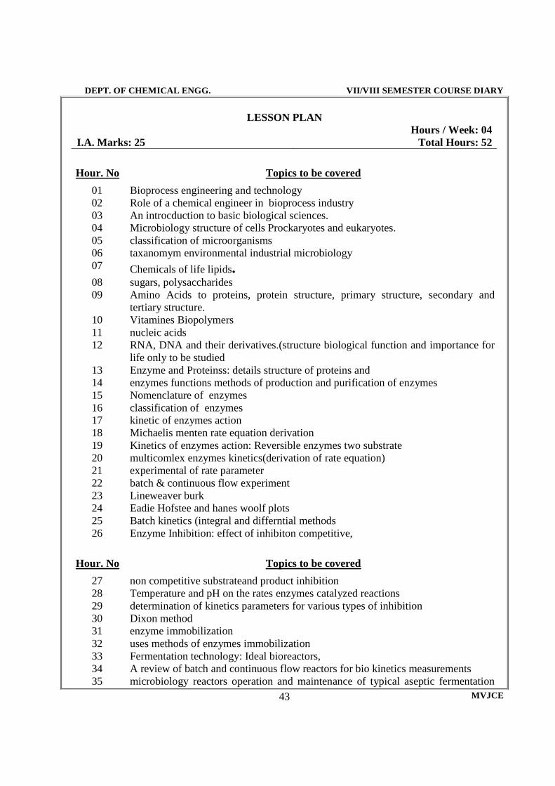
Hour. No Topics to be covered
01 Bioprocess engineering and technology 02 Role of a chemical engineer in bioprocess industry 03 An introcduction to basic biological sciences. 04 Microbiology structure of cells Prockaryotes and eukaryotes. 05 classification of microorganisms 06 taxanomym environmental industrial microbiology 07 Chemicals of life lipids. 08 sugars, polysaccharides 09 Amino Acids to proteins, protein structure, primary structure, secondary and
tertiary structure. 10 Vitamines Biopolymers 11 nucleic acids 12 RNA, DNA and their derivatives.(structure biological function and importance for
life only to be studied 13 Enzyme and Proteinss: details structure of proteins and 14 enzymes functions methods of production and purification of enzymes 15 Nomenclature of enzymes 16 classification of enzymes 17 kinetic of enzymes action 18 Michaelis menten rate equation derivation 19 Kinetics of enzymes action: Reversible enzymes two substrate 20 multicomlex enzymes kinetics(derivation of rate equation) 21 experimental of rate parameter 22 batch & continuous flow experiment 23 Lineweaver burk 24 Eadie Hofstee and hanes woolf plots 25 Batch kinetics (integral and differntial methods 26 Enzyme Inhibition: effect of inhibiton competitive,
Hour. No Topics to be covered
27 non competitive substrateand product inhibition 28 Temperature and pH on the rates enzymes catalyzed reactions 29 determination of kinetics parameters for various types of inhibition 30 Dixon method 31 enzyme immobilization 32 uses methods of enzymes immobilization 33 Fermentation technology: Ideal bioreactors, 34 A review of batch and continuous flow reactors for bio kinetics measurements 35 microbiology reactors operation and maintenance of typical aseptic fermentation

DEPT. OF CHEMICAL ENGG. VII/VIII SEMESTER COURSE DIARY
MVJCE 44
process. 36 formulataion of medium ,sources of nutrients, 37 alternate bioreactor configuration. 38 introduction to sterilization of bioprocess equipments 39 Growth Kinetics of microganisms: Transient growth kinetics (different phase of
batch cultivation) 40 Quantification of growth kinetics substrate limited growth. 41 ,models with growth inhibitor, logistic equation , 42 filaments cell growth model, 43 continuous culture optimum dilution rate in ideal chemostat 44 introduction to fed-batch reactors 45 Downstream processes: strategies and steps involved in product
purificatiaon 46 methods of cell disruption, - Filtration, centrifugation, sedimentation 47 chromatography freeze drying/lyophilization 48 menbrane separation technology 49 reverse osmosis ultra filtration 50 micro filtation dialyusis

DEPT. OF CHEMICAL ENGG. VII/VIII SEMESTER COURSE DIARY
MVJCE 45
QUESTION BANK 1. List out some important applications of biotechnology.
2. Discuss the difference between Procaryotic and Eucaryotic cells
3. What is the basis of the five-kingdom classification scheme according to Whittaker?
4. Why is Whittaker five-kingdom classification so accepted in the biological community?
5. Define the various Organelle’s of a typical caell and give their characteristics
6. Compare the general characteristics of the following. (a) Spirilla (b) Cocci (c) Bacilli (d) Budding (e) Sexual fusion (f) Sporulation
7. Why is it essential to classify microorganisms
8. What must be done before classification of microorganisms
9. Give the classification of microorganisms belonging to the kingdom protista
10. What are bacteria? Discuss their activity in biochemical process.
11. What do you understand by gram positive and gram-negative species?
12. If two microorganisms have an identical mol% G+c value for their DNA, are they necessarily related? Explain 13. If two microorganisms have a different mol% G+c value for their DNA, are they necessarily unrelated? Explain 14. Explain cell fractionation in biochemical analysis.
15. Bring out the importance of microorganisms in the fixation of nitrogen in the atmosphere.
16. Explain briefly the method of biological wastewater treatment.
17. State the different basic monomeric chemicals.
18. Give the basic molecular structure that forms the important super macromolecules in a living cell. 19. Distinguish the following
Amino acid and nucleic acid Lipids and proteins DNA & RNA Starch and glucose
20. Describe the death rate pattern of bacteria when exposed to a lethal agent.
21. Give the great range of protein structures and functions.
22. Discuss the diverse biological functions of proteins
23. What are lipids?
24. How are lipids classified?
25. What is rancidity?
26. How is rancidity prevented?

DEPT. OF CHEMICAL ENGG. VII/VIII SEMESTER COURSE DIARY
MVJCE 46
27. Discuss the biological and physiological role of lipids.
28. Define the meaning of a high-energy compound.
29. Name the high energy compound that occur in the glycol tic compound.
30. Suggest a method for sterilization for :
01 Petri Dish 05 A heat liable solution of vitamin 02 Water 06 A heat liable antibiotic solution 03 Nutrient Agar 07 Contaminated hospital linens 04 Dry powder 08 Operation room in hospitals
31. Write briefly on nitrogeneous bases that are found in DNA and RNA.
32. Distinguish between DNA & RNA
33. Distinguish between starch and glucose.
34. Define enzyme and a super enzyme
35. Enzyme carbonic anhydrase catalyses the hydration of carbon dioxide reaction: H2O + CO2 H2CO3
The molecular weight of the enzyme is 30000. If 10µg of pure enzyme catalyzes the hydration of 0.3 g of CO2 in 1 min at 370C under optimal condition calculate the turnover number of the enzyme. 36. Write the sequence of 3’ to 5’ end base for the following double helix 5’ AA TGCG3’ DNA nucleotide. Also write RNA strand for the same in 3’ to 5’ sequence. 37. Assuming the reaction sequence:
S+E
[ES1]
[ES1]
P + E
Develop a suitable expression using Quasi steady state approximation for the complexes.
38. Beef liver catalyst has been to used to accelerate the decomposition of H2O2 to yield water and oxygen. The concentration of water is given as a function of time for a reaction mixture with PH 6.76 maintained at 300 C.
Time (Secs) Concentration of H2O2 (mol/lit)
0 0.2 10 0.1775 20 0.0158 50 0.0106 100 0.022
a. Determine the M-M parameter b. If the total enzyme concentration is tripled, what will be the substrate concentration after 20 minutes? 39. Derive Michaelis-Menten equation for an enzyme-catalysed reaction.
40. Show how the Michaelis-Menten equation constants are evaluated by Lineweaver-Burk plot. 41. Discuss the effect of substrate concentration on the rate for the enzyme-catalysed reaction.

DEPT. OF CHEMICAL ENGG. VII/VIII SEMESTER COURSE DIARY
MVJCE 47
42. The following data were recorded for an enzyme reaction S = P. Estimate Vmax and Km
S, mol/l 8.33x10⁻⁶ 1.25x10⁻⁵ 3.33x10⁻⁵ 8x10⁻⁵ 2x10⁻⁴ V, mol/l. min 13.8 19.0 36.3 53.4 66.7
43. At room temperature Sucrose is hydrolysed by the catalytic action of the enzyme as Sucrose =
Product, Initial sucrose concentration CA0 = 1.0 mM/L and an enzyme concentration CE0 = 0.01 mM/L, the following data are obtained in a fresh batch reactor
Time (hr) CA mM/L Time (hr) CA mM/L 1 0.84 7 0.09 2 0.68 8 0.04 3 0.53 9 0.018 4 0.38 10 0.006 5 0.27 11 0.0025 6 0.16
Check whether the reaction follows MM model and if it fits the model then evaluate K3 and
M in the equation 44. For the enzymatic conversion of the substrate, the dependence of the reaction rate on the
substrate concentration is as given below: S [mM] 1 0.5 0.25 0.75 0.13 V min-1 71.4 55.5 40.1 30.3 25.2
i. Plot V Vs. S and find Vm and Km from the plot ii. Construct the Eadie-Hofstee plot and find Vm and Km from the same
45. What are the factors that affect the rate of enzymatic reactions?
46. Explain all the factors that affect the rate of enzymatic reactions.
47. What is enzyme inhibition?
48. What is the meaning of inhibitor constant KI?
49. Explain briefly ant two methods of estimation of the value of KI.
50. Derive the M-M equation for the reaction and a method to evaluate km, km1 when Vm = Vm1. Write the equation and what is the type of inhibition 51. The decarboxylation of glyoxylate by mitochondria is inhibited by malonate. In a kinetic study the following results were obtained. Is the inhibition of the reaction by malonate competitive? If so find the kinetic parameter.
-rA = K3CACE0 CA + M

DEPT. OF CHEMICAL ENGG. VII/VIII SEMESTER COURSE DIARY
MVJCE 48
Glyoxylate concentration mM
Rate of evolution of CO2 (arbitrary units) Malonate Concentration, mM
1.26 1.95 1.00 2.17 1.82 0.75 1.82 1.39 0.6 2.41 1.28 0.5 1.30 1.00 0.33 1.09 --- 0.25 1.01 ---
52. At room temperature the initial rate of reaction of enzymatic cleavage of de oxygnanosine triphosphate was measured as a function of concentration as follows.
Substrate concentration (µM/L) Initial Reaction Rate (µM/L min) Without inhibitor With inhibitor (1.46µM/L)
6.7 0.3 0.11 3.5 0.25 0.08 1.7 0.16 0.06
a. Calculate M-M constants b. What type of inhibition occurs when inhibitor of concentration 146 µM/L is added?
53. In the initial reaction rate of hydrolysis of acetyl choline (substrate) by dog serum (source of enzyme) in the acsence and presence of prostigmine (inhibitor), 1.5 x 10⁻⁷ M/L the following data were obtained.
Substrate concentration (M/L) Initial Reaction Rate (M/L min) Without inhibitor With inhibitor (1.46µM/L)
0.0032 0.111 0.59 0.0049 0.148 0.071 0.0062 0.143 0.091 0.0080 0.166 0.111 0.0095 0.200 0.125
Find the type of inhibition by prostigmine presence Find all the parameters that appear in the rate equation.
54. The enzyme, cathepsin, hydrolyses L-glutomyl – L-tyrosine to carbobenzoxy – L- glutamic acid and L tyrosine. It has been found that glutamic acid formed in the hydrolysis, inhibits (competitively), the progress of the reaction by forming a complex with cathepsin. The course of the reaction is followed by adding tyrosine decarboxylase, which evolves CO2
[S] µMml
[I] µMml
Rate of CO2 generation µMml-min
4.7 0 0.0434 4.7 7.57 0.0285 4.7 30.30 0.0133 10.8 0 0.0713 10.8 7.57 0.0512 10.8 30.30 0.0266 30.30 0 0.1111 30.30 7.57 0.0909 30.30 30.30 0.0581

DEPT. OF CHEMICAL ENGG. VII/VIII SEMESTER COURSE DIARY
MVJCE 49
Calculate a. The value of M-M constants of the enzyme
b. The dissociation constants of enzyme inhibitor complex KI 55. Give the partial classifications of reversible inhibitors. Describe them and give their effects on
kinetic parameters with different rate plots. 56. Derive the expression for the reaction velocity V, in terms of total enzyme concentration C0 and
free substrate and inhibitor concentrations, S for the following reactions E + S = ES KS: dissociation constant E = I = EI KI: dissociation constant ES = E + P slow step Where E & S are enzyme and substratr and I is the inhibitor. State how kinetic parameters are estimated?
57. Illustrate how reactions, the manner in which organically bound sulphur is released by microbial dissimilation. 58. Explain carbon dioxide cycle.
59. Describe how the physical composition of soil influences the magnitude and diversity of the microbial flora. 60. What are the components of bacterial nitrogen fixing system?
61. Explain nitrogen cycle.
62. What is oxidative phosphorylation?
63. Where does phosphorylation occur in the respiration chain?
64. What are the essential difference between photosynthesis by bacteria and algae?
65. Explain the following with the help of neat flow sheets: TCA cycle, Calvin cycle
66. What is meant by respiration?
67. Discuss respiration with the help of TCA cycle
68. Distinguish between catabolism and anabolism
69. Explain the following metabolic pathway briefly: EMP pathway, ATP cycle
70. What is carbon catabolism?
71. Write about electron transport and photophosphorylation.
DEPT. OF CHEMICAL ENGG. VII/VIII SEMESTER COURSE DIARY
MVJCE 50
DEPT. OF CHEMICAL ENGG. VII/VIII SEMESTER COURSE DIARY
MVJCE 51

DEPT. OF CHEMICAL ENGG. VII/VIII SEMESTER COURSE DIARY
MVJCE 52
06CH753 ELECTROCHEMICAL TECHNOLOGY

DEPT. OF CHEMICAL ENGG. VII/VIII SEMESTER COURSE DIARY
MVJCE 53
ELECTROCHEMICAL TECHNOLOGY Subject Code :
06CH753 IA Marks
: 25
No. of Lecture Hours/Week
: 04 Exam Hours
: 03
Total No. of Lecture Hours
: 52 Exam Marks
: 100
PART - A UNIT - 1
INTRODUCTION TO THEORETICAL ASPECTS: Faradays laws, mechanism of conduction in solids, liquids and gases and in ionic melts. Conduction in metals and semiconductors. 6 Hours
UNIT - 2 Reversible electrodes and potentials, electrode processes and electrode kinetics. 6 Hours
UNIT - 3 Various types of overpotentials. Polarisation. 6 Hours
UNIT - 4 Butler-volmer for one electron and mute electron steps. Models of electrical Double layer.
8 Hours PART – B UNIT - 5
Applied aspects: Potentiometry and ion-selective electrodes. Polaroraphy. 6 Hours
UNIT - 6 Electrode deposition of metals and alloys. 6 Hours
UNIT - 7 Primary, Secondary and Fuel Cells. 6 Hours
UNIT - 8 CORROSION AND ITS PREVENTION:. Electro winning. Electro organic and inorganic synthesis (and some typical examples). Environmental electrochemistry. Bio-electro chemistry.
8 Hours
TEXT BOOKS:
1. Modern Electrochemistry - J.O.M., Bockris & A.K.N. Reddy, Vol.1 & 2, Plenum, New York 2002.
2. Industrial Electrochemical Processes - A. Kuhn,, Elsevier, Amsterdam 1971.
REFERENCE BOOKS:
1. Electro Analytical Chemistry - J.J. Lingane, Wiley, New York-1958.
2. Electrochemistry, Principles and Applications - E.C. Potter, Cleaverhume Press, London 1956.
3. Organic Electrochemistry - M.M. Baizer, Marcel Dekker, New York – 1991.

DEPT. OF CHEMICAL ENGG. VII/VIII SEMESTER COURSE DIARY
MVJCE 54
06CH754 – SUGAR TECHNOLOGY

DEPT. OF CHEMICAL ENGG. VII/VIII SEMESTER COURSE DIARY
MVJCE 55
SYLLABUS Hours / Week: 4 I A Marks: 25 Exam Hours: 3 Exam Marks: 100
PART-A UNIT-I 1. Sugar Industry in India: Chemical and physical properties of sucrose and reducing sugars. Sources for sucrose, formation of sucrose plants, non-sugar compounds of sugar cane, inorganic constituents of sugar cane juices and sugars analytical methods used in sugar industry. 6 Hrs. UNIT-II 2. Purification: Chemical technology of purification process, fundamental reactions and physical chemistry aspects of clarification, liming, sulphitation and carbonation process, filtration of sugar juices. 8 Hrs. UNIT-III Evaporation: Evaporation of sugar juice, heat transfer in evaporators, evaporation equipments and auxiliaries. 6hrs UNIT-IV Evaporation Methods of obtaining steam, and quality of steam. Steam economy, chemistry of the evaporation process. 6Hrs.
PART-B UNIT-V Chrystallography : Solubility of sucrose, nucleation in super saturated solutions –kinetics and growth of crystallization, chemistry of crystallization, 7hrs UNIT-VI Chrystallography:control methods & equipment in sugar crystallization, technology of sugar crystallization, evaporation & circulation in vacuum pans. 7 Hrs. UNIT-VII Centrifugation : Theory of the centrifugal process, centrifugal operation, 4hrs UNIT-VII Centrifugation: engineering principles of sugar centrifugals and the centrifugal equipment and auxiliaries, production of final molasses and molasses’s utilization, grading of sugar. 8 Hrs. TEXT BOOKS : 1.Honing P. (Ed). “Principles of Sugar technology”, Vol. I to III, Elsivier Publishing Company, 1953. 2. Jerkins, G.H. Introduction of Cane Sugar Technolgy, Elsivier, 1966. REFERENCE BOOKS : 1. Mathur, R.B.L., Handbook of Cane Sugar Technology, 2nd edn. Oxford and I.B.H. Publishing Co., 1997. 2. Jink. R.W. and Pan Coast H.M., Hand book of Sugars, Avi Publishing Co., 1974.
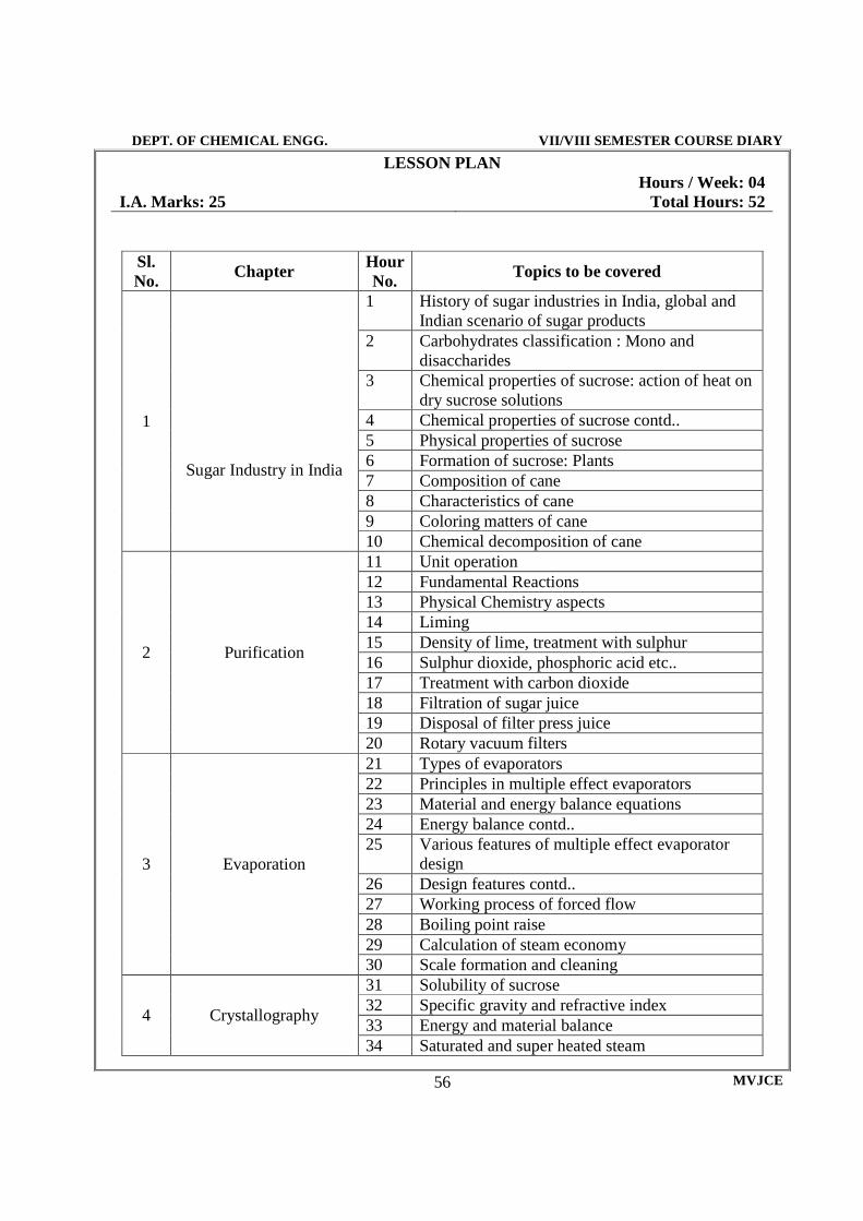
DEPT. OF CHEMICAL ENGG. VII/VIII SEMESTER COURSE DIARY
MVJCE 56
LESSON PLAN Hours / Week: 04 I.A. Marks: 25 Total Hours: 52
Sl. No. Chapter Hour
No. Topics to be covered
1
Sugar Industry in India
1 History of sugar industries in India, global and Indian scenario of sugar products
2 Carbohydrates classification : Mono and disaccharides
3 Chemical properties of sucrose: action of heat on dry sucrose solutions
4 Chemical properties of sucrose contd.. 5 Physical properties of sucrose 6 Formation of sucrose: Plants 7 Composition of cane 8 Characteristics of cane 9 Coloring matters of cane 10 Chemical decomposition of cane
2 Purification
11 Unit operation 12 Fundamental Reactions 13 Physical Chemistry aspects 14 Liming 15 Density of lime, treatment with sulphur 16 Sulphur dioxide, phosphoric acid etc.. 17 Treatment with carbon dioxide 18 Filtration of sugar juice 19 Disposal of filter press juice 20 Rotary vacuum filters
3 Evaporation
21 Types of evaporators 22 Principles in multiple effect evaporators 23 Material and energy balance equations 24 Energy balance contd.. 25 Various features of multiple effect evaporator
design 26 Design features contd.. 27 Working process of forced flow 28 Boiling point raise 29 Calculation of steam economy 30 Scale formation and cleaning
4 Crystallography
31 Solubility of sucrose 32 Specific gravity and refractive index 33 Energy and material balance 34 Saturated and super heated steam

DEPT. OF CHEMICAL ENGG. VII/VIII SEMESTER COURSE DIARY
MVJCE 57
35 Nucleation in crystallization 36 Crystal growth 37 Types of crystallization 38 Control methods 39 Chemistry and technology 40 Evaporation and circulation in pans
5 Centrifugation
41 Theory of centrifugation 42 Centrifugal operation; Double curing 43 Factors affecting curing rates 44 Factors affecting curing rates contd.. 45 Engineering principles of centrifugation 46 Continuous centrifuges 47 Centrifugal equipments 48 Conical Type centrifuges 49 Coproducts of sugar cans 50 Molasses utilisation 51 Alcohol industry 52 Grading and drying of sugar

DEPT. OF CHEMICAL ENGG. VII/VIII SEMESTER COURSE DIARY
MVJCE 58
QUESTION BANK 1. Discuss the present scenario of Indian Sugar Industry in relation to world sugar Industry? 2. Mention the chemical and physical properties of sucrose and reducing sugars. 3. Explain the factors to be considered for establishment of sugar plants. 4. Explain the factors to be considered for proper layout of sugar factory. 5. What are the various milling processes employed in sugar industry? 6. Explain the working of any 2 milling equipments with neat sketches. 8. What is compound imbibition? Explain with neat sketch. 9. What is the purpose of sugar cane juice clarification? 10. What are the various chemicals used in the clarification of juice? 11. What are the colouring matters present in cane juice? Explain 12. Explain the methods of removing the coloring matter from the cane juice. 13. With neat sketches explain the production of sulphur and sulphur dioxide. 14. What are the various sulphitation processes employed in juice purification? Explain. 15. What are the various carbonatation processes employed in juice purification? Explain 16. What factors decide the type of clarification for the cane juice? 17. Explain with a neat sketch the working of a multiple effect evaporator. 18. What are the causes for the entrainment in the evaporators? 19. How are the entrainments removed in the evaporators? 20. Explain the methods of circulation of sugar syrup in the crystallizer pans. 21. Explain the working of any one sugar juice clarifier. Explain the methods of sugar seeding in the pans. 22. What are the various grades of sugar massecuites obtained in the crystallizers? 23. Explain the process of sugar drying in the rotary dryer. 24. What are the various grades of sugars? 25. Explain the working of centrifugals. 26. What are various types of evaporators used in the sugar industry? Explain their working with
neat sketches.

DEPT. OF CHEMICAL ENGG. VII/VIII SEMESTER COURSE DIARY
MVJCE 59

DEPT. OF CHEMICAL ENGG. VII/VIII SEMESTER COURSE DIARY
MVJCE 60
DEPT. OF CHEMICAL ENGG. VII/VIII SEMESTER COURSE DIARY
MVJCE 61
06CH763 PETROCHEMICALS
DEPT. OF CHEMICAL ENGG. VII/VIII SEMESTER COURSE DIARY
MVJCE 62
06CH763 PETROCHEMICALS
Subject Code : 06CH763
IA Marks
: 25
No. of Lecture Hours/Week
: 04 Exam Hours
: 03
Total No. of Lecture Hours
: 52 Exam Marks
: 100
PART - A UNIT - 1
DEFINITION OF PETROCHEMICALS: Petrochemical. Industries in India. Principal raw materials. Introduction to chemicals from C1, C2, C3 and C4 compounds. 4 Hours
UNIT - 2
CHEMICALS FROM C1 COMPOUNDS: Manufacture of methanol and chloromethanes. Manufacture of perchloro ethylene. 6 Hours
UNIT - 3
CHEMICALS FROM C2 COMPOUNDS: Ethylene and acetylene, ethanol, polyethylene, ethylene dichloride, acetaldehyde, vinyl chloride, ethylene oxide, ethanol amines, vinyl acetate, acetic acid. 8 Hours
UNIT - 4
CHEMICAL FROM C3 COMPOUNDS: Isopropanol, acetone, lumen (isopropyl benzene), acrylonitrile, isoprene, polypropylene, epichlorohydrin, propylene oxide. 8 Hours
PART - B UNIT - 5
CHEMICAL FROM C4 COMPOUNDS: Butadiene dehydrogenation of butane (Houdry). Dehydrogenation of butylenes. Dehydrogenation-dehydration of ethanol. Steam cracking of hydrocarbons. 8 Hours

DEPT. OF CHEMICAL ENGG. VII/VIII SEMESTER COURSE DIARY
MVJCE 63
UNIT - 6
CHEMICALS FROM AROMATICS : Primary raw material. Hydroalkylation. 5 Hours
UNIT - 7 Manufacture of phenol – 5 methods. Styrene – 2 methods. Pthalic anhydride amleic anhydride, nitrobenzene, aniline. 8 Hours
UNIT - 8
Manufacture of industrial dyes based on petroleum feed stocks. 5 Hours
TEXT BOOKS:
1. Petrochemicals- By B.K.B. Rao CRC Press –1990. 2. Chem Tech II, III and IV – Published by Chemical Engg. Education developments centre
IIT, Madras 1979.
REFERENCE BOOKS:
1. Outlines of Chemical Technology - Gopal Rao M and Marshall Sittig 3rd Edition, East-West Press 1997.
2. Chemical process industries - 5th edition- Shreve McGrew Hill 1984. 3. Chemical Technology- G.N. Pandey 3rd Edition 1977. 4. Chemical Technology- Mukhlyonov-Mir Publications-1982.

DEPT. OF CHEMICAL ENGG. VII/VIII SEMESTER COURSE DIARY
MVJCE 64
06CH764-OIL AND FATS

DEPT. OF CHEMICAL ENGG. VII/VIII SEMESTER COURSE DIARY
MVJCE 65
SYLLABUS
Sub code: 06CH764 I A Marks: 25 Hours / Week: 04 Exam Hours: 03 Total Hours: 52 Exam Marks: 100
PART-A
Unit-1 INTRODUCTION –Classification of fats and oil, characteristics of oils. Utilization of fats and oils. Composition of oils. (General). 6hrs Unit-2 VEGETABLES OILS-Composition. Extraction. Refining processes and uses of coconut oil, cottonseed oil. 7hrs
Unit-3
VEGETABLES OILS-Composition. Extraction. Refining processes and uses of palm oil, Soya been oil, sunflower oil. 7 hrs
Unit-4 MARINE OILS - Composition. Extraction. Refining processes and uses of fish oils. 6 hrs
PART-B
Unit-5 OBTAINING OILS AND FATS FROM SOURCE MATERIALS- mechanical pretreatment, mechanical expression solvent extraction (two types of extractors). 10hrs
Unit-6 PROCESS TECHNIQUES- Refining and hydrogenation (H2 production and catalyst) 6hrs
Unit-7 PROCESS TECHNIQUES-Degumming. Alkali Refining and bleaching. 6hrs
Unit-8 DEODORIZATION - Theoretical consideration and operation of commercial deodorizer. 4hrs

DEPT. OF CHEMICAL ENGG. VII/VIII SEMESTER COURSE DIARY
MVJCE 66
TEXT BOOKS 1. Basily industrial oil and fats products-Vol I to V-Y.H.Hery John Wiley Internataional,2nd
Edition-1976 REFERENCES
1.Chemistry And Technology Of Oils And Fats-Devine j and Williams P.N 1961 2.Chemical Process Industrials –Austin G.T , Shreve’s fifth edition, Mc graw-hill international Book Company, Singapore 1984 3.Outlines Of Chemical Technology- Dryden C.E., edited by Gopala Rao, M and M. Sitting, Second Edition, Affiliated East West Press 1993 4.Hand Book Of Industrial Chemistry- Kent J.A (Ed) Riegel’s Van Nostrand Reinhold,1974.
DEPT. OF CHEMICAL ENGG. VII/VIII SEMESTER COURSE DIARY
MVJCE 67
LESSON PLAN Hours / Week: 04
I.A. Marks: 25 Total Hours: 52
Hour. No Topics to be covered
1 Introduction of fats and oil 2 Classification of fats 3 Classification of oil 4 Characteristics of oils. 5 Utilization of fats and oils. 6 Composition of oils 7 Composition of Vegetables Oils 8 Extraction of Vegetables Oils 9 Composition of Vegetables Oils 10 Refining processes of coconut oil. 11 Uses of coconut oil 12 Refining processes of cottonseed oil. 13 Uses of cottonseed oil. 14 Composition of palm oil Soya been oil, 15 Extraction of Soya been oil, 16 Composition of sunflower oil. 17 Refining processes of Soya been oil, 18 Uses of Soya been oil, 19 Refining processes of sunflower oil. 20 Uses of sunflower oil 21 Composition extraction of marine oils 22 Extraction of marine oils 23 Refining processes & use of marine oils, 24 Extraction of fish oils 25 Refining processes of fish oils, 26 Uses of fish oil, 27 Obtaining oils from source materials 28 Obtaining oils from source materials like plants 29 Obtaining oils from source materials like animals 30 Mechanical Pretreatment for oils 31 Mechanical Pretreatment for fats 32 Obtaining fats from source materials

DEPT. OF CHEMICAL ENGG. VII/VIII SEMESTER COURSE DIARY
MVJCE 68
33 Mechanical expression for fats 34 Mechanical expression for oils 35 Solvent extraction (two types of extractors) 36 Recent advance in solvent extraction 37 Introduction to process techniques 38 Refining 39 Hydrogenation 40 H2 production 41 Catalyst 42 Advantages and Disadvantages of the above procees 43 Introduction to process techniques -. 44 degumming 45 Alkali refining. 46 Bleaching. 47 Advance processing techniques of the above procees 48 Advantages and Disadvantages 49 Deodorization 50 Theoretical consideration 51 Operation of commercial deodorizer 52 Recent advance in the above process.

DEPT. OF CHEMICAL ENGG. VII/VIII SEMESTER COURSE DIARY
MVJCE 69
QUESTION BANK Time-3hrs Max Marks-100 Note- 1. Answer any FIVE full questions.
2. Draw the process flow sheet wherever necessary.
1 a. Explain in detail the classification of oils and fats. (17 Marks) b. Explain batch solvent extractor of oils. (03 Marks) 2 a. Describe the process of extracting cotton seed oil with flow sheet. (14Marks) b. Explain the composition of cotton seed oil. (06Marks) a. Explain the conventional fish meal process for extracting fish oil with flow sheet, and unit operations. (14 Marks) b. Explain the major industrial uses of fish oil. (06Marks) 4 a. Name the various pretreatment of oil seeds, explain one treatment in detail. (10 Marks)
b. With neat sketch explain vertical basket type of extractor. (10 Marks) 5 Explain in details methods of coconut oil extraction. (20 Marks)
6 a. How the degumming of oil is done? Describe. (10 Marks) b. Explain the bleaching technique of oil. (10 Marks) 7 Explain with flow sheets continuous and semi continuous process for deodorization of oil.
(20 Marks)
8 Write short notes on – (20 Marks) a. Utilization of oils b. Peanut oil extraction c. Characteristics of oils d. Immersion extractor

DEPT. OF CHEMICAL ENGG. VII/VIII SEMESTER COURSE DIARY
MVJCE 70
06CHL77 – PROCESS CONTROL LAB

DEPT. OF CHEMICAL ENGG. VII/VIII SEMESTER COURSE DIARY
MVJCE 71
SYLLABUS Hours / Week: 3 I A Marks: 25 Exam Hours: 4 Exam Marks: 50
List of Experiments:
1. Time constant determination and response to step change of thermometer, pressure – I order
2. Single tank system – step responde
3. Non Interacting – step responde
4. Interacting – step responde
5. Pressure system
6. U tube manometer
7. single tank –impulse response
8. Non interacting tanks-impulse response
9. interacting tank –impulses response
10. level /flow pressure/pH/temperature control- Pcontroller
11. level /flow pressure/pH/temperature control- PIcontroller
12. level /flow pressure/pH/temperature control- PDcontroller
13. level /flow pressure/pH/temperature control- PIDcontroller
14. valve characteristics
15. flapper nozzle system
16. valve positioner
Note: Minimum of 10 experiments from above choosing are to be conducted.
DEPT. OF CHEMICAL ENGG. VII/VIII SEMESTER COURSE DIARY
MVJCE 72
LESSON PLAN Hours / Week: 04 I.A. Marks: 25 Total Hours: 42
I – CYCLE EXPERIMENTS
1.Time constant determination and response to step change of thermometer, pressure – I order
2. Single tank system – step responde
3. Non Interacting – step responde
4.Interacting – step responde 5.level /flow pressure/pH/temperature control- Pcontroller 6.Pressure system
Hour. No Topics to be covered
1-3 Instruction for the – I cycle of experiments. 4-6 Experiment number 1 for group 1
Experiment number 2 for group 2 Experiment number 3 for group 3 Experiment number 4 for group 4 Experiment number 5 for group 5 Experiment number 6 for group 6
7-9 Experiment number 2 for group 1 Experiment number 3 for group 2 Experiment number 4 for group 3 Experiment number 5 for group 4 Experiment number 6 for group 5 Experiment number 1 for group 6
10-12 Experiment number 3 for group 1 Experiment number 4 for group 2 Experiment number 5 for group 3 Experiment number 6 for group 4 Experiment number 1 for group 5 Experiment number 2 for group 6
13-15 Experiment number 4 for group 1 Experiment number 5 for group 2 Experiment number 6 for group 3 Experiment number 1 for group 4 Experiment number 2 for group 5 Experiment number 3 for group 6
16-18 Experiment number 5 for group 1 Experiment number 6 for group 2 Experiment number 1 for group 3 Experiment number 2 for group 4

DEPT. OF CHEMICAL ENGG. VII/VIII SEMESTER COURSE DIARY
MVJCE 73
Experiment number 3 for group 5 Experiment number 4 for group 6
II – CYCLE EXPERIMENTS 7.level /flow pressure/pH/temperature control- PIcontroller
8.level /flow pressure/pH/temperature control- PDcontroller
9.level /flow pressure/pH/temperature control- PIDcontroller
10.valve characteristics
11.flapper nozzle system
12.valve positioner
Hour. No Topics to be covered 19-21 Instruction for the II cycle of experiments 22-24 Experiment number 7 for group 1
Experiment number 6 for group 2 Experiment number 9 for group 3 Experiment number 10 for group 4 Experiment number 11 for group 5 Experiment number 12 for group 6
25-27 Experiment number 8 for group 1 Experiment number 9 for group 2 Experiment number 10 for group 3 Experiment number 11 for group 4 Experiment number 12 for group 5 Experiment number 7 for group 6
28-30 Experiment number 9 for group 1 Experiment number 10 for group 2 Experiment number 11for group 3 Experiment number 12 for group 4 Experiment number 7 for group 5 Experiment number 8 for group 6
31-33 Experiment number 10 for group 1 Experiment number 11 for group 2 Experiment number 12 for group 3 Experiment number 7 for group 4 Experiment number 8 for group 5 Experiment number 9 for group 6
34-36 Experiment number 11 for group 1 Experiment number 12 for group 2 Experiment number 7 for group 3 Experiment number 8 for group 4 Experiment number 9 for group 5
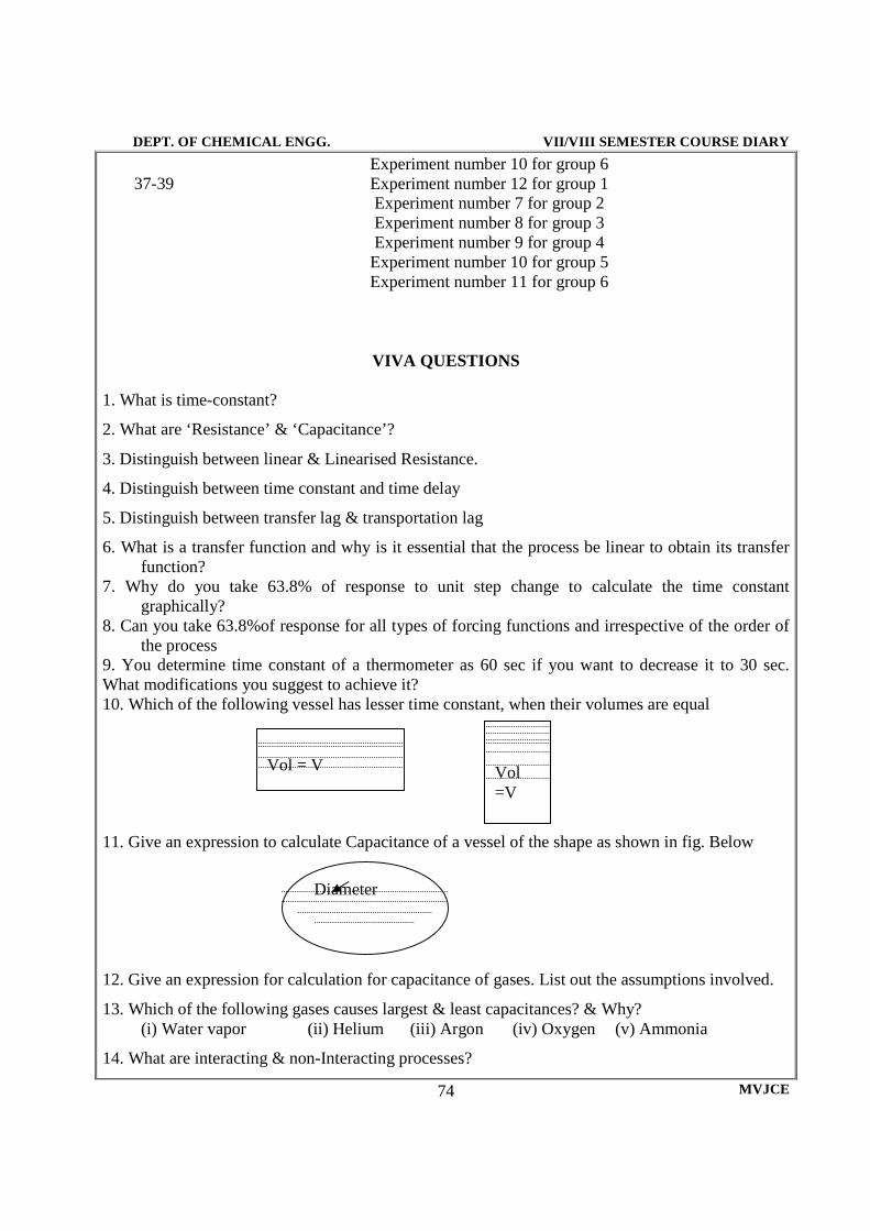
DEPT. OF CHEMICAL ENGG. VII/VIII SEMESTER COURSE DIARY
MVJCE 74
Experiment number 10 for group 6 37-39 Experiment number 12 for group 1
Experiment number 7 for group 2 Experiment number 8 for group 3 Experiment number 9 for group 4 Experiment number 10 for group 5 Experiment number 11 for group 6
VIVA QUESTIONS
1. What is time-constant?
2. What are ‘Resistance’ & ‘Capacitance’?
3. Distinguish between linear & Linearised Resistance.
4. Distinguish between time constant and time delay
5. Distinguish between transfer lag & transportation lag
6. What is a transfer function and why is it essential that the process be linear to obtain its transfer function?
7. Why do you take 63.8% of response to unit step change to calculate the time constant graphically?
8. Can you take 63.8%of response for all types of forcing functions and irrespective of the order of the process
9. You determine time constant of a thermometer as 60 sec if you want to decrease it to 30 sec. What modifications you suggest to achieve it? 10. Which of the following vessel has lesser time constant, when their volumes are equal 11. Give an expression to calculate Capacitance of a vessel of the shape as shown in fig. Below 12. Give an expression for calculation for capacitance of gases. List out the assumptions involved.
13. Which of the following gases causes largest & least capacitances? & Why? (i) Water vapor (ii) Helium (iii) Argon (iv) Oxygen (v) Ammonia
14. What are interacting & non-Interacting processes?
Vol = V
Vol =V
Diameter

DEPT. OF CHEMICAL ENGG. VII/VIII SEMESTER COURSE DIARY
MVJCE 75
15. Give different classifications of interacting & non-interacting processes
16. What are advantages and disadvantages (give at least one each) over non-interacting processes
17. How do you usually represent a 6th order process?
18. How do you overcome the difficulty of presence of dead-time element in a closed Loop control system
19. What is damping? & Damping co-efficient? Give examples of processes with different damping co-efficient
20. Say True or False: by manipulations & changes one can make a two tank non-interacting
process to be made to be under damped process 21. Say True or False: A two-tank process with equal values of time-constants (identical Resistance
& capacitance) will always be over damped 22. What is proportional gain? What is proportional bandwidth?
23. If proportional sensitivity is 60%, the level ranges from 0-250 mm, what is the corresponding proportional band?
24. What are the advantages & disadvantages of combining I action with proportional action?
25. What is the effect of adding D action with proportional action?
26. What is offset? Explain briefly with suitable example (s)
27. For a particular setting of a proportional controller of kc the offset is, say, 5%. If kc is increased the offset (i) will increase (ii) will remain constant (iii) decreases
28. For a particular setting of a PI controller the corresponding damping co-efficient is ξ. If the integral time is decreased with kc held constant, the damping co-efficient, ξ. , i) will increase (ii) will remain constant (iii) decreases 29. What do you understand by ‘order’ of a reaction?
30. Distinguish between ‘order’ & ‘molecularly’ of a reaction
31. What is specific about ‘specific reaction rate constant?
32. What are ‘elementary & non-elementary’ reactions?
33. Give the balanced reaction of reactants you use in your experiments. What is its name? State whether it is an elementary & non-elementary’ reaction? 34. What are the usual methods of analyzing & determining the order and ‘k’ of a reaction? Explain briefly 35. If ‘k’ is k1 in a batch reactor, it will be (i) greater (ii) lesser (iii) equal to k1 if the reaction is
carried in a mixed flow reactor 36. If ‘k’ is k1 in a batch reactor, it will be (i) greater (ii) lesser (iii) equal to k1 if the reaction is
carried in a tubular flow reactor 37. If ‘k’ is k2 at temp=T1 ‘k’ will (a) remain the same (b) increases (c) decreases at a higher temp,
T2 38. What are space-time & space velocity?
39. What is meant by residence time?
40. What are reasons for non-ideality of flow reactors?
DEPT. OF CHEMICAL ENGG. VII/VIII SEMESTER COURSE DIARY
MVJCE 76
41. What are C, E & F curves?
42. What is type of input you usually give to study the non-ideality of flow reactors? What are their names?
43. What are the characteristics of a tracer?
44. What are ‘mean, variance and standard deviation and how do you calculate them?
45. What is dispersion number?
46. What are batch, plug and mixed flow reactors?
47. If the dispersion number is very large, then the actual reactor approaches ideal plug flow! TRUE or FALSE
48. If the dispersion number is very small, then the actual reactor approaches ideal plug flow! TRUE or FALSE

DEPT. OF CHEMICAL ENGG. VII/VIII SEMESTER COURSE DIARY
MVJCE 77
06CHL78 – COMPUTER APPLICATIONS & SIMULATION LAB

DEPT. OF CHEMICAL ENGG. VII/VIII SEMESTER COURSE DIARY
MVJCE 78
SYLLABUS Hours / Week: 3 I A Marks: 25 Exam Hours: 4 Exam Marks: 50
List of Experiments:
PART A
1. Non linear algebric equation Newton Raphson (Specific volume of binary mixture)
2. Ordinary Differential equation RK Method (dCA/dt = KCa2).
3. Numerical Integration – Simpsons 1/3 rule (Batch Reactor to find time)
4. Curve fitting – Least square (Nre V/s f)
5. Calculation of bubble point and dew point for ideal multi component system
6. Flash Calculation for multi component mixtures
7. Design of adiabatic Batch reactor, PFR
8. Adiabatic flame temperature
9. Double pipe heat exchanger (Area, Length and pressure)
10. Distillation column (Bubble cap)
PART B
1. Introduction to suggested software available (flow sheeting).
2. Simulation studies of flash drum, distillation column, CSTR, PFR, Heat exchanger
3. Simulation studies of pump, compressor, cyclone, heater
4. Process simulation study involving mixing, reactor, Distillation, Heat exchanger, any of the following process
a). Ethylene glycol form ethylene oxide
b). Atmospheric distillation of crude oil
c). Phthalic anhydride process
d). Aromatic stripper with recycle stream (Benzene, Toulene, Xylene)
e). Styrene from Ethyl Benzene
Note: One question form PART A Excluding Numerical Techniques – 20 Marks One question from PART B (Simulation of any above process) – 30 Marks

DEPT. OF CHEMICAL ENGG. VII/VIII SEMESTER COURSE DIARY
MVJCE 79
LESSON PLAN Hours / Week: 03 I.A. Marks: 25 Total Hours: 42
1. Bubble point temperature for ideal binary and multi component mixtures 2. Dew point temperature for ideal binary and multi component mixtures 3. Flash vaporization for multi component mixtures. 4. Design of adiabatic CSTR. . 5. Design of adiabatic PFR
Hour. No Topics to be covered
1-3 Instruction for the – I cycle of experiments. 4-6 Experiment number 1 for group 1
Experiment number 2 for group 2 Experiment number 3 for group 3 Experiment number 4 for group 4 Experiment number 5 for group 5 Experiment number 6 for group 6
7-9 Experiment number 2 for group 1 Experiment number 3 for group 2 Experiment number 4 for group 3 Experiment number 5 for group 4 Experiment number 6 for group 5 Experiment number 1 for group 6
10-12 Experiment number 3 for group 1 Experiment number 4 for group 2 Experiment number 5 for group 3 Experiment number 6 for group 4 Experiment number 1 for group 5 Experiment number 2 for group 6
13-15 Experiment number 4 for group 1 Experiment number 5 for group 2 Experiment number 6 for group 3 Experiment number 1 for group 4 Experiment number 2 for group 5 Experiment number 3 for group 6
16-18 Experiment number 5 for group 1 Experiment number 6 for group 2 Experiment number 1 for group 3 Experiment number 2 for group 4 Experiment number 3 for group 5 Experiment number 4 for group 6

DEPT. OF CHEMICAL ENGG. VII/VIII SEMESTER COURSE DIARY
MVJCE 80
II – CYCLE EXPERIMENTS
5. Design of distillation column 6. Simulation studies of heat exchanger 7. Simulation studies of distillation column 8. Simulation studies of ethylene glycol from ethylene oxide 9. Aromatic stripper with recycle stream (Benzene, Toluene, Xylene)
Hour. No Topics to be covered 19-21 Instruction for the II cycle of experiments
22-24
Experiment number 7 for group 1 Experiment number 6 for group 2 Experiment number 9 for group 3 Experiment number 10 for group 4 Experiment number 11 for group 5 Experiment number 12 for group 6
25-27
Experiment number 8 for group 1 Experiment number 9 for group 2 Experiment number 10 for group 3 Experiment number 11 for group 4 Experiment number 12 for group 5 Experiment number 7 for group 6
28-30
Experiment number 9 for group 1 Experiment number 10 for group 2 Experiment number 11for group 3 Experiment number 12 for group 4 Experiment number 7 for group 5 Experiment number 8 for group 6
31-33
Experiment number 10 for group 1 Experiment number 11 for group 2 Experiment number 12 for group 3 Experiment number 7 for group 4 Experiment number 8 for group 5 Experiment number 9 for group 6
34-36
Experiment number 11 for group 1 Experiment number 12 for group 2 Experiment number 7 for group 3 Experiment number 8 for group 4 Experiment number 9 for group 5 Experiment number 10 for group 6
37-39
Experiment number 12 for group 1 Experiment number 7 for group 2 Experiment number 8 for group 3 Experiment number 9 for group 4 Experiment number 10 for group 5 Experiment number 11 for group 6

DEPT. OF CHEMICAL ENGG. VII/VIII SEMESTER COURSE DIARY
MVJCE 81
VIVA QUESTIONS
1. What is the difference between mainframe and mini frame?
2. What is Syntax error?
3. What is a platform?
4. What are the High level and Low-level language?
5. How does a machine language is converted to High level language
6. What are Analog computer and Digital computer?
7. Why programming is necessary in Chemical engineering
8. What is Main function and function
9. What are the inbuilt files in C language?
10. What are sub functions and subroutine functions?
11. What is Bubble and Dew point?
12. Batch reactor, Mixed flow reactor, Plug flow reactor: where all it is used
13. What is exothermic and endothermic reaction?
14. Distinguish between isothermal and non-isothermal reactions
15. Define reaction rate constant
16. Differentiate reaction rate and rate constant
17. What is space velocity and time?
18. Differentiate between integral analysis method and differential analysis method
19. What are equations of states?
20. Differential between Raoult’s law and Henry’s law
21. Differentiate between ideal and non-ideal solutions
22. What are virial-coefficients?
23. Define Gibb’s free energy and fugacity coefficient
24. What is Vapour liquid equilibrium?
25. Define Dalton’s law
26. Differentiate between steady state and unsteady state conduction
27. Define LMTD
28. Significance of LMTD
29. Which flow in Heat exchanger is more convenient?
30. What is LMTD correction factor and why is it necessary?
31. Will the Boiling point of a solution increases or decreases with pressure