department of computer sci. &engineering lab …...practical/lab sessions related cloud...
TRANSCRIPT
1
Department of Computer Sci. &Engineering
LAB MANUAL
BE(CSE)
Cloud COMPUTING

2
MGM's Jawaharlal Nehru Engineering College, Aurangabad
Jawaharlal Nehru Engineering College Aurangabad
Laboratory Manual
Cloud Computing
For
Final Year Students CSE
Dept: Computer Science & Engineering
Author JNEC, Aurangabad

3
FOREWORD
It is my great pleasure to present this laboratory manual for FINAL YEAR
COMPUTER SCIENCE & ENGINEERING students for the subject of Cloud
Computing. As a student, many of you may be wondering about the subject and
exactly that has been tried through this manual.
As you may be aware that MGM has already been awarded with ISO 9000 certification
and it is our aim to technically equip students taking the advantage of the procedural
aspects of ISO 9000 Certification.
Faculty members are also advised that covering these aspects in initial stage
itself will relieve them in future as much of the load will be taken care by the
enthusiastic energies of the students once they are conceptually clear.
Dr. S.D. Deshmukh
Principal

4
LABORATORY MANUAL CONTENTS
This manual is intended for FIANL YEAR COMPUTER SECINCE & ENGINEERING
students for the subject of Cloud Computing. This manual typically contains
practical/Lab Sessions related cloud computing Paa,Saas,Iaas,etc covering various
aspects related the subject to enhanced understanding.
Students are advised to thoroughly go through this manual rather than only topics
mentioned in the syllabus as practical aspects are the key to understanding and
conceptual visualization of theoretical aspects covered in the books.
Good Luck for your Enjoyable Laboratory Sessions.
Dr. V.B. Musande Mr.Sujeet S More Mr.Sharad Jadhav HOD, CSE CSE Dept

5
DOs and DON’Ts in Laboratory:
1. Make entry in the Log Book as soon as you enter the Laboratory.
2. All the students should sit according to their roll numbers starting from
their left to right.
3. All the students are supposed to enter the terminal number in the log book.
4. Do not change the terminal on which you are working.
5. All the students are expected to get at least the algorithm of the
program/concept to be implemented.
6. Strictly observe the instructions given by the teacher/Lab Instructor.
Instruction for Laboratory Teachers::
1. Submission related to whatever lab work has been completed should be done
during the next lab session. The immediate arrangements for printouts related to
submission on the day of practical assignments.
2. Students should be taught for taking the printouts under the observation of lab
teacher.
3. The promptness of submission should be encouraged by way of marking and
evaluation patterns that will benefit the sincere students.

6
MGM’s
Jawaharlal Nehru Engineering College, Aurangabad
Department of Computer Science and Engineering
Vision of CSE Department
To develop computer engineers with necessary analytical ability and human values who can creatively design, implement a wide spectrum of computer systems for welfare of the society.
Mission of the CSE Department:
Preparing graduates to work on multidisciplinary platforms associated with their professional Position both independently and in a team environment. Preparing graduates for higher education and research in computer science and engineering enabling them to develop systems for society Development.
Programme Educational Objectives
Graduates will be able to
I. To analyze, design and provide optimal solution for Computer Science & Engineering
and multidisciplinary problems. II. To pursue higher studies and research by applying knowledge of mathematics and
fundamentals of computer science. III. To exhibit professionalism, communication skills and adapt to current trends by engaging
in lifelong learning.

7
Programme Outcomes (POs):
Engineering Graduates will be able to: 1. Engineering knowledge: Apply the knowledge of mathematics, science, engineering
fundamentals, and an engineering specialization to the solution of complex engineering problems.
2. Problem analysis: Identify, formulate, review research literature, and analyze complex engineering problems reaching substantiated conclusions using first principles of mathematics, natural sciences, and engineering sciences.
3. Design/development of solutions: Design solutions for complex engineering problems
anddesign system components or processes that meet the specified needs with appropriate consideration for the public health and safety, and the cultural, societal, and environmental considerations.
4. Conduct investigations of complex problems: Use research-based knowledge and research
methods including design of experiments, analysis and interpretation of data, and synthesis of the information to provide valid conclusions.
5. Modern tool usage: Create, select, and apply appropriate techniques, resources, and modern
engineering and IT tools including prediction and modeling to complex engineering activities with an understanding of the limitations.
6. The engineer and society: Apply reasoning informed by the contextual knowledge to assess
societal, health, safety, legal and cultural issues and the consequent responsibilities relevant to the professional engineering practice.
7. Environment and sustainability: Understand the impact of the professional engineering
solutions in societal and environmental contexts, and demonstrate the knowledge of, and need for sustainable development.
8. Ethics: Apply ethical principles and commit to professional ethics and responsibilities and
norms ofthe engineering practice. 9. Individual and team work: Function effectively as an individual, and as a member or leader
in diverse teams, and in multidisciplinary settings. 10. Communication: Communicate effectively on complex engineering activities with the
engineering community and with society at large, such as, being able to comprehend and write effective reports and design documentation, make effective presentations, and give and receive clear instructions.
11. Project management and finance: Demonstrate knowledge and understanding of the engineering and management principles and apply these to one’s own work, as a member and leader in a team, to manage projects and in multidisciplinary environments.
12. Life-long learning: Recognize the need for, and have the preparation and ability to engage
independent and life-long learning in the broadest context of technological change.

8
SUBJECT INDEX
Sr. No. Title Page
No.
1 Introduction to cloud computing. 9
2
Creating a Warehouse Application in SalesForce.com.
14
3
Creating an Application in SalesForce.com using Apex
programming Language.
17
4
Implementation of SOAP Web services in C#/JAVA
Applications.
19
5
Implementation of Para-Virtualization using VM Ware‘s Workstation/ Oracle‘s Virtual Box and Guest O.S.
27
6
Installation and Configuration of Hadoop.
37
7
Create an application (Ex: Word Count) using Hadoop
Map/Reduce.
41
8
Case Study: PAAS(Facebook, Google App Engine)
49
9
Case Study: Amazon Web Services.
65

9
Class: BE(CSE) Subject: Lab I- Cloud Computing
Experiment No. 1
_______________________________________________________________ Aim: To study in detail about cloud computing.
Theory:
The term cloud has been used historically as a metaphor for the Internet. This
usage was originally derived from its common depiction in network diagrams as an outline of
a cloud, used to represent the transport of data across carrier backbones (which owned the
cloud) to an endpoint location on the other side of the cloud. This concept dates back as early
as 1961, when Professor John McCarthy suggested that computer time-sharing technology
might lead to a future where computing power and even specific applications might be sold
through a utility-type business model. 1 This idea became very popular in the late 1960s, but
by the mid-1970s the idea faded away when it became clear that the IT-related technologies of
the day were unable to sustain such a futuristic computing model. However, since the turn of
the millennium, the concept has been revitalized. It was during this time of revitalization that
the term cloud computing began to emerge in technology circles. Cloud computing is a model
for enabling convenient, on-demand network access to a shared pool of configurable
computing resources (e.g., networks, servers, storage, applications, and services) that can be
rapidly provisioned and released with minimal management effort or service provider
interaction .A Cloud is a type of parallel and distributed system consisting of a collection of
inter-connected and virtualized computers that are dynamically provisioned and presented as
one or more unified computing resource(s) based on service-level agreements established
through negotiation between the service provider and consumers.
When you store your photos online instead of on your home computer, or use
webmail or a social networking site, you are using a cloud computing service. If you are in an
organization, and you want to use, for example, an online invoicing service instead of
updating the in-house one you have been using for many years, that online invoicing service is
a ―cloud computing service. Cloud computing is the delivery of computing services over the
Internet. Cloud services, Allow individuals and businesses to use software and hardware that
are managed by third parties at remote locations. Examples of cloud services include online
file storage, social networking sites, webmail, and online business applications. The cloud
computing model allows access to information and computer resources from anywhere. Cloud

10
computing provides a shared pool of resources, including data storage space, networks,
Computer processing power, and specialized corporate and user applications. Architecture
Cloud Service Models
Cloud Deployment Models
Essential Characteristics of Cloud Computing
NIST Visual Model of Cloud Computing Definition
Cloud Service Models
Cloud Software as a Service (SaaS)
Cloud Platform as a Service (PaaS)
Cloud Infrastructure as a Service (IaaS)

11
Infrastructure as a Service (IaaS):--
The capability provided to the consumer is to provision processing, storage, networks, and other fundamental computing resources.
Consumer is able to deploy and run arbitrary software, which can include operating systems and applications.
The consumer does not manage or control the underlying cloud infrastructure but has control over operating systems; storage, deployed applications, and possibly limited control of select
networking components (e.g., host firewalls).
Platform as a Service (PaaS):--
The capability provided to the consumer is to deploy onto the cloud infrastructure consumer created or acquired applications created using programming languages and tools supported by the provider.
The consumer does not manage or control the underlying cloud infrastructure including network, servers, operating systems, or storage, but has control over the deployed applications and
Possibly application hosting environment configurations.

12
Software as a Service (SaaS):--
The capability provided to the consumer is to use the provider‘s applications running on a cloud infrastructure.
The applications are accessible from various client devices through a thin client interface such as a web browser (e.g., web-based email).
The consumer does not manage or control the underlying cloud infrastructure including network, servers, operating systems, storage, or even individual application capabilities, with the possible exception of limited user specific application configuration settings.

13
Cloud Deployment Models:
Public
Private
Community Cloud
Hybrid Cloud
Public Cloud:The cloud infrastructure is made available to the general public or a large
industry group and is owned by an organization selling cloud services.
Private Cloud: The cloud infrastructure is operated solely for a single organization. It may be managed by the organization or a third party, and may exist on-premises or off-premises.
Community Cloud:The cloud infrastructure is shared by several organizations and supports a specific community that has shared concerns (e.g., mission, security requirements, policy, or compliance considerations). It may be managed by the organizations or a third party and may exist on-premises or off-premises.
Hybrid Cloud: The cloud infrastructure is a composition of two or more clouds (private, community, or public) that remain unique entities but are bound together by standardized or
Proprietary technology that enables data and application portability (e.g., cloud bursting
for load-balancing between clouds).
ESSENTIAL CHARACTERISTICS:-- On-demand self-service:--A consumer can unilaterally provision computing capabilities
such as server time and network storage as needed automatically, without requiring human interaction with a service provider.
Broad network access:--Capabilities are available over the network and accessed through standard mechanisms that promote use by heterogeneous thin or thick client
platforms (e.g., mobile phones, laptops, and PDAs) as well as other traditional or cloud
based software services.

14
Resource pooling:--The provider‘s computing resources are pooled to serve multiple
consumers using a multi-tenant model, with different physical and virtual resources
dynamically assigned and reassigned according to consumer demand.
Rapid elasticity:--Capabilities can be rapidly and elastically provisioned in some cases automatically - to quickly scale out; and rapidly released to quickly scale in. To
the consumer, the capabilities available for provisioning often appear to be unlimited and
can be purchased in any quantity at any time.
Measured service:--Cloud systems automatically control and optimize resource usage by leveraging a metering capability at some level of abstraction appropriate to the type of service. Resource usage can be monitored, controlled, and reported - providing transparency for both the provider and consumer of the service.
Conclusion:
Thus we have studied in detail about overview of cloud computing
*****

15
Class: BE(CSE) Subject: Lab I- Cloud Computing
Experiment No. 2
_______________________________________________________________ Aim: Creating a Warehouse Application in SalesForce.com‘s Force.com.
Theory:
Steps to create an application in Force.com by declarative model
Step 1: Click on Setup
Create
Objects
New custom object
Label: MySale Pular Label: MySales
Object Name: MySale
Record Name: MySale Description
Data Type: Text
Click on Save.
Step 2: Under MySale Go to Custom Field and Relationships
Click on New Custom Field
Creating 1st
Field:--
select Data type as Auto Number
next
Enter the details
Field Label: PROD_ID
Display Format: MYS-{0000}
Starting Number: 1001
Field Name: PRODID
Next
Save & New
Creating 2nd
Field:--
select Data type as Date
next
Enter the details
Field Label: Date of Sale
Field Name: Date_of_Sale
Default Value: Today()-1
Next
Save & New
Creating 3rd
Field:--
select Data type as Number
next
16
Enter the details
Field Label: Quantity Sold
Length:3
Decimal places:0
Default Value: Show Formulae Editor:1
Next
Save & New
Creating 4th
Field:--
select Data type as Currency
next
Enter the details
Field Label: Rate
Field Name: Rate
Length:4
Decimal places:2
Default Value: 10
Next
Save & New
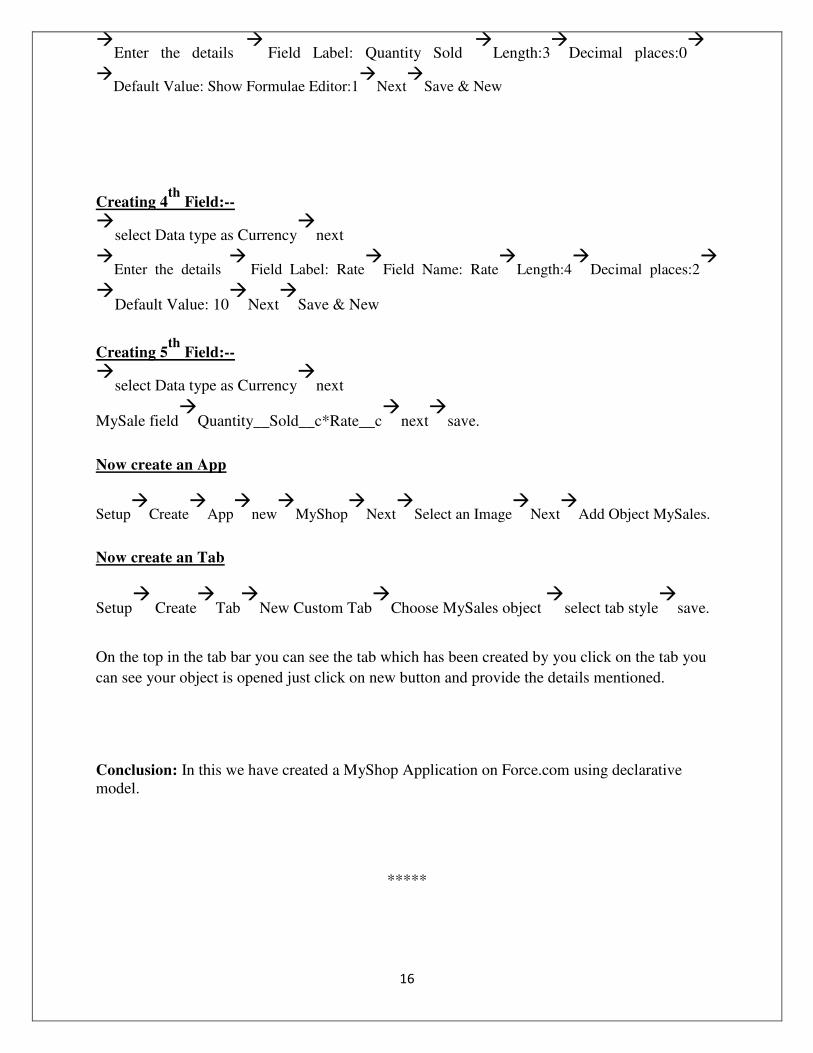
Creating 5th
Field:--
select Data type as Currency
next
MySale field
Quantity__Sold__c*Rate__c
next
save.
Now create an App
Setup
Create
App
new
MyShop
Next
Select an Image
Next
Add Object MySales.
Now create an Tab
Setup
Create
Tab
New Custom Tab
Choose MySales object
select tab style
save.
On the top in the tab bar you can see the tab which has been created by you click on the tab you
can see your object is opened just click on new button and provide the details mentioned.
Conclusion: In this we have created a MyShop Application on Force.com using declarative model.
*****

17
Class: BE(CSE) Subject: Lab I- Cloud Computing
Experiment No. 3
_______________________________________________________________
Aim: Creating an Application in SalesForce.com using Apex programming Language. Theory: Step1:
Log into your Sandbox or Developers Organization.
Click on setup
create
objects
new custom objects.
Enter Book for label. Enter Books for plural label.
Click Save.
Step 2:
Now let‘s create a custom field.
In the custom field & relationship section of the Book Object click new.
Select Number for the datatype & next.
Enter Price for the field Label.
Enter 16 in the length text box.
Enter 2 in the decimal places & Next….next…. save.
Step 3:
Clilck setup
Develop
Apex Classes & click new
In the class Editor enter this class public class MyHelloWorld{
public static void applyDiscount(Book__c[] books)
{
for(Book__c b:books)

18
{b.Price__c*=0.9;}
} } Step 4: Add a trigger
A trigger is a piece of code that can execute objects before or after specific data manipulation
language events occurred.
Click on setup
create
objects
click the object you have created ex:
Book Scroll down you can see Trigger Click on New
In the trigger Editor enter this class trigger HelloWorldTrigger on Book__c(before insert) { Book__c[] books=Trigger.new; MyHelloWorld.applyDiscount(books); }
Step 5:
Click on setup
create
tabs
new custom tab
choose Book
next&.next&..save.
Click on tab Books
new
insert a name for Book
insert price for that book
click on
save.
Conclusion:
Thus we have studied how to create and run an application in salesforce developers site by using APEX programming language.
*****

19
Class: BE(CSE) Subject: Lab I- Cloud Computing
Experiment No. 4
_______________________________________________________________
Aim: To study & Implement Web services in SOAP for JAVA Applications.
Theory:
Overview of Web Services
Web services are application components that are designed to support interoperable machine-
to-machine interaction over a network. This interoperability is gained through a set of XML-
based open standards, such as the Web Services Description Language (WSDL), the Simple
Object Access Protocol (SOAP), and Universal Description, Discovery, and Integration
(UDDI). These standards provide a common and interoperable approach for defining,
publishing, and using web services. Choosing a Container:
You can either deploy your web service in a web container or in an EJB container. This
depends on your choice of implementation. If you are creating a Java EE application, use a
web container in any case, because you can put EJBs directly in a web application. For
example, if you plan to deploy to the Tomcat Web Server, which only has a web container,
create a web application, not an EJB module.
Choose File > New Project. Select Web Application from the Java Web category
.Name the project Calculator WS Application. Select a location for the
project. Click Next.
Select your server and Java EE version and click Finish. Creating a Web Service from a Java Class
Right-click the Calculator WS Application node and choose New > Web Service.
Name the web service Calculator WS and type org.me.calculator in
Package. Leave Create Web Service from Scratch selected.

20
If you are creating a Java EE project on GlassFish or WebLogic, select Implement Web
Service as a Stateless Session Bean.
Click Finish. The Projects window displays the structure of the new web service and the
source code is shown in the editor area.
Adding an Operation to the Web Service
The goal of this exercise is to add to the web service an operation that adds two numbers
received from a client. The NetBeans IDE provides a dialog for adding an operation to a web
service. You can open this dialog either in the web service visual designer or in the web service
context menu. To add an operation to the web service:
Change to the Design view in the editor.

21
Click Add Operation in either the visual designer or the context menu. The Add
Operation dialog opens.
In the upper part of the Add Operation dialog box, type add in Name and type int in
the Return Type drop-down list.
In the lower part of the Add Operation dialog box, click Add and create a parameter of
type int named i.
Click Add again and create a parameter of type int called j.
Click OK at the bottom of the Add Operation dialog box. You return to the editor.
Remove the default hello operation, either by deleting the hello() method in the source
code or by selecting the hello operation in the visual designer and clicking Remove
Operation.
The visual designer now displays the following:

22
Click Source and view the code that you generated in the previous steps. It differs whether
you created the service as a Java EE stateless bean or not. Can you see the difference in the
screenshots below? (A Java EE 6 or Java EE 7 service that is not implemented as a stateless
bean resembles a Java EE 5 service.) Note. In NetBeans IDE 7.3 and 7.4 you will notice that in the generated @WebService annotation the service name is specified explicitly:@WebService(serviceName = "CalculatorWS").
9. In the editor, extend the skeleton add operation to the following (changes are in bold):
@WebMethod
public int add(@WebParam(name = "i") int i, @WebParam(name = "j") int j) {
int k = i + j;
return k;
}
As you can see from the preceding code, the web service simply receives two numbers and then
returns their sum. In the next section, you use the IDE to test the web service.

23
Deploying and Testing the Web Service
After you deploy a web service to a server, you can use the IDE to open the server's test client, if
the server has a test client. The GlassFish and WebLogic servers provide test clients.
If you are using the Tomcat Web Server, there is no test client. You can only run the project and
see if the Tomcat Web Services page opens. In this case, before you run the project, you need to
make the web service the entry point to your application. To make the web service the entry
point to your application, right-click the CalculatorWSApplication project node and choose
Properties. Open the Run properties and type /CalculatorWS in the Relative URL field. Click
OK. To run the project, right-click the project node again and select Run. To test successful deployment to a GlassFish or WebLogic server:
Right-click the project and choose Deploy. The IDE starts the application server, builds
the application, and deploys the application to the server. You can follow the progress of
these operations in the CalculatorWSApplication (run-deploy) and the GlassFish server
or Tomcat tabs in the Output view.
2. In the IDE's Projects tab, expand the Web Services node of the
CalculatorWSApplication project. Right-click the CalculatorWS node, and
choose Test Web Service.
The IDE opens the tester page in your browser, if you deployed a web application to the
GlassFish server. For the Tomcat Web Server and deployment of EJB modules, the
situation is different:
If you deployed to the GlassFish server, type two numbers in the tester page, as shown below:
Consuming the Web Service
Now that you have deployed the web service, you need to create a client to make use of the web
service's add method. Here, you create three clients— a Java class in a Java SE application, a
servlet, and a JSP page in a web application.

24
Note: A more advanced tutorial focusing on clients is Developing JAX-WS Web Service Clients.
Client 1: Java Class in Java SE Application
In this section, you create a standard Java application. The wizard that you use to create the
application also creates a Java class. You then use the IDE's tools to create a client and consume
the web service that you created at the start of this tutorial.
Choose File > New Project (Ctrl-Shift-N on Linux and Windows, ⌘-Shift-N on MacOS).
Select Java Application from the Java category. Name the
projectCalculatorWS_Client_ Application. Leave Create Main Class selected and
accept all other default settings. Click Finish.
Right-click the CalculatorWS_Client_Application node and choose New > Web
Service Client. The New Web Service Client wizard opens.
Select Project as the WSDL source. Click Browse. Browse to the CalculatorWS web service
in the CalculatorWSApplication project. When you have selected the web service, click OK.
Do not select a package name. Leave this field empty.
Leave the other settings at default and click Finish.
The Projects window displays the new web service client, with a node for the add method that
you created:
Double-click your main class so that it opens in the Source Editor. Drag the add node
below the main() method.

25
Note: Alternatively, instead of dragging the add node, you can right-click in the editor
and then choose Insert Code > Call Web Service Operation.
8. In the main() method body, replace the TODO comment with code that initializes
values for i and j, calls add(), and prints the result.
9. public static void main(String[]
args) { int i = 3;

26
int j = 4;
int result = add(i, j);
System.out.println("Result = " +
result);
}
Right-click the project node and choose Run.
The Output window now shows
the sum: compile:
ru
n:
Re
sul
t =
7
BUILD SUCCESSFUL (total time: 1 second)
Conclusion: Thus we have studied use of webservices using SOAP for a java application.
*****

27
Class: BE(CSE) Subject: Lab I- Cloud Computing
Experiment No. 5
_______________________________________________________________ Experiment Title: Implementation of Para-Virtualization using VM Ware‘s Workstation/ Oracle‘s Virtual Box and Guest O.S.
Aim: Implementation of Virtual Box for Virtualization of any OS.
Theory:
Virtual Box is a cross-platform virtualization application. What does that mean? For one thing,
it installs on your existing Intel or AMD-based computers, whether they are running Windows,
Mac, Linux or Solaris operating systems. Secondly, it extends the capabilities of your existing
computer so that it can run multiple operating systems (inside multiple virtual machines) at the
same time. So, for example, you can run Windows and Linux on your Mac, run Windows
Server 2008 on your Linux server, run Linux on your Windows PC, and so on, all alongside
your existing applications. You can install and run as many virtual machines as you like the
only practical limits are disk space and memory. Virtual Box is deceptively simple yet also
very powerful. It can run everywhere from small embedded systems or desktop class machines
all the way up to datacenter deployments and even Cloud environments.
The techniques and features that Virtual Box provides are useful for several scenarios:
Running multiple operating systems simultaneously. Virtual Box allows you to run
more than one operating system at a time. This way, you can run software written for
one operating system on another (for example, Windows software on Linux or a Mac)
without having to reboot to use it. Since you can configure what kinds of "virtual"
hardware should be presented to each such operating system, you can install an old
operating system such as DOS or OS/2 even if your real computer's hardware is no
longer supported by that operating system.
Easier software installations. Software vendors can use virtual machines to ship entire
software configurations. For example, installing a complete mail server solution on a
real machine can be a tedious task. With Virtual Box, such a complex setup (then often
called an "appliance") can be packed into a virtual machine. Installing and running a
mail server becomes as easy as importing such an appliance into Virtual Box.

28
Testing and disaster recovery. Once installed, a virtual machine and its virtual hard
disks can be considered a "container" that can be arbitrarily frozen, woken up, copied,
backed up, and transported between hosts.
Infrastructure consolidation. Virtualization can significantly reduce hardware and
electricity costs. Most of the time, computers today only use a fraction of their potential
power and run with low average system loads. A lot of hardware resources as well as
electricity is thereby wasted. So, instead of running many such physical computers that
are only partially used, one can pack many virtual machines onto a few powerful hosts
and balance the loads between them. Some Terminologies used:
When dealing with virtualization (and also for understanding the following chapters of this
documentation), it helps to acquaint oneself with a bit of crucial terminology, especially the
following terms:
Host operating system (host OS). This is the operating system of the physical computer
on which Virtual Box was installed. There are versions of Virtual Box for Windows, Mac OS X,
Linux and Solaris hosts.
Guest operating system (guest OS).This is the operating system that is running inside the
virtual machine. Theoretically, Virtual Box can run any x86 operating system (DOS, Windows, OS/2,
FreeBSD, Open BSD), but to achieve near-native performance of the guest code on your machine, we
had to go through a lot of optimizations that are specific to certain operating systems. So while your
favorite operating system may run as a guest, we officially support and optimize for a select few (which,
however, include the most common ones).
Virtual machine (VM). This is the special environment that Virtual Box creates for your guest
operating system while it is running. In other words, you run your guest operating system "in" a VM.
Normally, a VM will be shown as a window on your computers desktop, but depending on which of the
various frontends of VirtualBox you use, it can be displayed in full screen mode or remotely on another
computer. In a more abstract way, internally, VirtualBox thinks of a VM as a set of parameters that
determine its behavior. They include
hardware settings (how much memory the VM should have, what hard disks VirtualBox should virtualize
through which container files, what CDs are mounted etc.) as well as state information (whether the VM
is currently running, saved, its snapshots etc.). These settings are mirrored in the VirtualBox Manager
window as well as the VBoxManage command line program;

29
Guest Additions. This refers to special software packages which are shipped with VirtualBox but
designed to be installed inside a VM to improve performance of the guest OS and to add extra features.
Starting Virtual Box: After installation, you can start VirtualBox as follows:
On a Windows host, in the standard "Programs" menu, click on the item in the
"VirtualBox" group. On Vista or Windows 7, you can also type "VirtualBox" in the
search box of the "Start" menu.
On a Mac OS X host, in the Finder, double-click on the "VirtualBox" item in the
"Applications" folder. (You may want to drag this item onto your Dock.)
On a Linux or Solaris host, depending on your desktop environment, a "VirtualBox" item
may have been placed in either the "System" or "System Tools" group of your
"Applications" menu. Alternatively, you can type VirtualBox in a terminal.
When you start VirtualBox for the first time, a window like the following should come up:

30
This window is called the "VirtualBox Manager". On the left, you can see a pane that will later
list all your virtual machines. Since you have not created any, the list is empty. A row of buttons
above it allows you to create new VMs and work on existing VMs, once you have some. The
pane on the right displays the properties of the virtual machine currently selected, if any. Again,
since you don't have any machines yet, the pane displays a welcome message.
To give you an idea what VirtualBox might look like later, after you have created many
machines, here's another example:
Creating your first virtual machine:
Click on the "New" button at the top of the VirtualBox Manager window. A wizard will pop up
to guide you through setting up a new virtual machine (VM)

31
On the following pages, the wizard will ask you for the bare minimum of information that is needed to create a VM, in particular:
The VM name will later be shown in the VM list of the VirtualBox Manager window,
and it will be used for the VM's files on disk. Even though any name could be used, keep
in mind that once you have created a few VMs, you will appreciate if you have given
your VMs rather informative names; "My VM" would thus be less useful than "Windows
XP SP2 with OpenOffice".
For "Operating System Type", select the operating system that you want to install later.
The supported operating systems are grouped; if you want to install something very
unusual that is not listed, select "Other". Depending on your selection, Virtual Box will
enable or disable certain VM settings that your guest operating system may require. This
is particularly important for 64-bit guests (see Section 3.1.2,64-bit guests). It is therefore
recommended to always set it to the correct value.

32
On the next page, select the memory (RAM) that Virtual Box should allocate every time
the virtual machine is started. The amount of memory given here will be taken away from
your host machine and presented to the guest operating system, which will report this size
as the (virtual) computer's installed RAM.
A Windows XP guest will require at least a few hundred MB RAM to run properly, and
Windows Vista will even refuse to install with less than 512 MB. Of course, if you want
to run graphics-intensive applications in your VM, you may require even more RAM.
So, as a rule of thumb, if you have 1 GB of RAM or more in your host computer, it is usually safe to allocate 512 MB to each VM. But, in any case, make sure you always have at least 256 to 512 MB of RAM left on your host operating system. Otherwise you may cause your host OS to excessively swap out memory to your hard disk, effectively bringing your host system to a standstill. As with the other settings, you can change this setting later, after you have created the VM.
4. Next, you must specify a virtual hard disk for your VM. There are many and potentially
complicated ways in which VirtualBox can provide hard disk space to a VM (see Chapter 5,
Virtual storage for details), but the most common way is to use a large image file on your "real"
hard disk, whose contents VirtualBox presents to your VM as if it were a complete hard disk.
This file represents an entire hard disk then, so you can even copy it to another host and use it
with another VirtualBox installation.
The wizard shows you the following window:
Here you have the following options:

33
To create a new, empty virtual hard disk, press the "New" button.
You can pick an existing disk image file. The drop-down list presented in the window
contains all disk images which are currently remembered by VirtualBox, probably
because they are currently attached to a virtual machine (or have been in the past).
Alternatively, you can click on the small folder button next to the drop-down list to
bring up a standard file dialog, which allows you to pick any disk image file on your host
disk.
Most probably, if you are using VirtualBox for the first time, you will want to create a new
disk image. Hence, press the "New" button. This brings up another window, the "Create
New Virtual Disk Wizard", which helps you create a new disk image file in the new virtual
machine's folder.
VirtualBox supports two types of image files:
A dynamically allocated file will only grow in size when the guest actually stores
data on its virtual hard disk. It will therefore initially be small on the host hard drive
and only later grow to the size specified as it is filled with data.
A fixed-size file will immediately occupy the file specified, even if only a fraction of
the virtual hard disk space is actually in use. While occupying much more space, a
fixed-size file incurs less overhead and is therefore slightly faster than a dynamically
allocated file.
For details about the differences, please refer to Section 5.2,Disk image files (VDI, VMDK,
VHD, HDD.
After having selected or created your image file, again press "Next" to go to the next page.
After clicking on "Finish", your new virtual machine will be created. You will then see it in
the list on the left side of the Manager window, with the name you entered initially.

34
Running your virtual machine: To start a virtual machine, you have several options:
Double-click on its entry in the list within the Manager window or
select its entry in the list in the Manager window it and press the "Start" button at the top or
for virtual machines created with VirtualBox 4.0 or later, navigate to the "VirtualBox
VMs" folder in your system user's home directory, find the subdirectory of the machine
you want to start and double-click on the machine settings file (with a .vbox file
extension). This opens up a new window, and the virtual machine which you selected will
boot up. Everything which would normally be seen on the virtual system's monitor is
shown in the window. In general, you can use the virtual machine much like you would
use a real computer. There are couple of points worth mentioning however.
Saving the state of the machine: When you click on the "Close" button of your virtual machine
window (at the top right of the window, just like you would close any other window on your

35
system), VirtualBox asks you whether you want to "save" or "power off" the VM. (As a shortcut,
you can also press the Host key together with "Q".)
The difference between these three options is crucial. They mean:
Save the machine state: With this option, VirtualBox "freezes" the virtual machine by
completely saving its state to your local disk. When you start the VM again later, you will
find that the VM continues exactly where it was left off. All your programs will still be
open, and your computer resumes operation. Saving the state of a virtual machine is thus
in some ways similar to suspending a laptop computer (e.g. by closing its lid).
Send the shutdown signal. This will send an ACPI shutdown signal to the virtual
machine, which has the same effect as if you had pressed the power button on a real
computer. So long as the VM is running a fairly modern operating system, this should
trigger a proper shutdown mechanism from within the VM.
Power off the machine: With this option, VirtualBox also stops running the virtual
machine, but without saving its state. As an exception, if your virtual machine has any
snapshots (see the next chapter), you can use this option to quickly restore the current
snapshot of the virtual
machine. In that case, powering off the machine will not disrupt its state, but any changes
made since that snapshot was taken will be lost. The "Discard" button in the VirtualBox

36
Manager window discards a virtual machine's saved state. This has the same effect as
powering it off, and the same warnings apply.
Importing and exporting virtual machines
VirtualBox can import and export virtual machines in the industry-standard Open Virtualization
Format (OVF). OVF is a cross-platform standard supported by many virtualization products
which allows for creating ready-made virtual machines that can then be imported into a
virtualizer such as VirtualBox. VirtualBox makes OVF import and export easy to access and
supports it from the Manager window as well as its command-line interface. This allows for
packaging so-called virtual appliances: disk images together with configuration settings that
can be distributed easily. This way one can offer complete ready-to-use software packages
(operating systems with applications) that need no configuration or installation except for
importing into VirtualBox.
Appliances in OVF format can appear in two variants:
They can come in several files, as one or several disk images, typically in the widely-
used VMDK format (see Section 5.2,Disk image files (VDI, VMDK, VHD, HDD)‖)
and a textual description file in an XML dialect with an .ovf extension. These files must
then reside in the same directory for Virtual Box to be able to import them.
Alternatively, the above files can be packed together into a single archive file, typically
with an .ova extension. (Such archive files use a variant of the TAR archive format and
can therefore be unpacked outside of Virtual Box with any utility that can unpack
standard TAR files.)
Select "File" -> "Export appliance". A different dialog window shows up that allows you to
combine several virtual machines into an OVF appliance. Then, select the target location where
the target files should be stored, and the conversion process begins. This can again take a while.
Conclusion: Thus we have studied use of Multiple OS using Virtual Box by virtualizing.
*****

37
Class: BE(CSE) Subject: Lab I- Cloud Computing
Experiment No. 6
_______________________________________________________________
Aim: Installation and Configuration of Hadoop.
Theory:
Hadoop-1.2.1 Installation Steps for Single-Node Cluster (On Ubuntu 12.04)
Download and install VMware Player depending on your Host OS (32 bit or 64 bit
https://my.vmware.com/web/vmware/free#desktop_end_user_computing/vmware_play
er/6_0
Download the .iso image file of Ubuntu 12.04 LTS (32-bit or 64-bit depending on your
requirements) http://www.ubuntu.com/download/desktop
Install Ubuntu from image in VMware. (For efficient use, configure the Virtual Machine to
have at least 2GB (4GB preferred) of RAM and at least 2 cores of processor
----------------JAVA INSTALLATION---------------
sudo mkdir -p /usr/local/java
cd ~/Downloads
sudo cp -r jdk-8-linux-i586.tar.gz /usr/local/java
sudo cp -r jre-8-linux-i586.tar.gz /usr/local/java
cd /usr/local/java
sudo tar xvzf jdk-8-linux-i586.tar.gz
sudo tar xvzf jre-8-linux-i586.tar.gz
ls a jdk1.8.0 jre1.8.0 jdk-8-linux-i586.tar.gz jre-8-linux-i586.tar.gz

38
sudo gedit /etc/profile
JAVA_HOME=/usr/local/java/jdk1.7.0_4
PATH=$PATH:$HOME/bin:$JAVA_HOME
/binJRE_HOME=/usr/local/java/jdk1.7.0_45/j
rePATH=$PATH:$HOME/bin:$JRE_HOME/
binHADOOP_HOME=/home/hadoop/adoop-
1.2.1
PATH=$PATH:$HADOOP_HOME/binexpor
t JAVA_HOME export JRE_HOME export
PATH
sudo update-alternatives --install "/usr/bin/java" "java" "/usr/local/java/jdk1.8.0/jre/bin/java" 1
sudo update-alternatives --install "/usr/bin/javac" "javac" "/usr/local/java/jdk1.8.0/bin/javac" 1
13.sudo update-alternatives --install "/usr/bin/javaws" "javaws" "/usr/local/java/jdk1.8.0/bin/javaws" 1
sudo update-alternatives --set java /usr/local/java/jdk1.8.0/jre/bin/java
sudo update-alternatives --set javac /usr/local/java/jdk1.8.0/bin/javac
sudo update-alternatives --set javaws /usr/local/java/jdk1.8.0/bin/javaws
. /etc/profile
java -version
java version "1.8.0" Java(TM) SE Runtime Environment (build 1.8.0-b132) Java HotSpot(TM) Client VM (build 25.0-b70, mixed mode)
---------------------HADOOP INSTALLATION------------------
open Home
create a floder hadoop
copy from downloads hadoop-1.2.1.tar.gz to hadoop
right click on hadoop-1.2.1.tar.gz and Extract Here
cd hadoop/

39
ls -a
. .. hadoop-1.2.1 hadoop-1.2.1.tar.gz 25. edit the
file conf/hadoop-env.sh
# The java implementation to use. Required. export
JAVA_HOME=/usr/local/java/jdk1.8.0 26. cd hadoop-1.2.1
------------------STANDALONE OPERATION----------------
mkdir input
cp conf/*.xml input
bin/hadoop jar hadoop-examples-*.jar grep input output 'dfs[a-z.]+'
cat output/* ----------------PSEUDO DISTRIBUTED OPERATION---------------//WORDCOUNT
conf/core-site.xml:
<configuration> <property> <name>fs.default.name</name> <value>hdfs://localhost:9000</value> </property> </configuration>
conf/hdfs-site.xml:
<configuration> <property>
<name>dfs.replication</name> <value>1</value> </property> </configuration>

40
conf/mapred-site.xml:
<configuration> <property> <name>mapred.job.tracker</name> <value>localhost:9001</value> </property> </configuration>
ssh localhost
ssh-keygen -t dsa -P '' -f ~/.ssh/id_dsa
cat ~/.ssh/id_dsa.pub >> ~/.ssh/authorized_keys
bin/hadoop namenode -format
bin/start-all.sh
Run the following command to verify that hadoop services are running $ jps If everything was successful, you should see following services running
2583 DataNode 2970 ResourceManager 3461 Jps 3177 NodeManager 2361 NameNode 2840 SecondaryNameNode
Conclusion: Thus we have studied how to install and configure hadoop on Ubuntu operating system.
*****

41
Class: BE(CSE) Subject: Lab I- Cloud Computing
Experiment No. 7
_______________________________________________________________
Aim: Create an application (Ex: Word Count) using Hadoop Map/Reduce.
Theory:
THE MAPREDUCE MODEL
Traditional parallel computing algorithms were developed for systems with a small number of
processors, dozens rather than thousands. So it was safe to assume that processors would not
fail during a computation. At significantly larger scales this assumption breaks down, as was
experienced at Google in the course of having to carry out many large-scale computations
similar to the one in our word counting example. The MapReduce parallel programming
abstraction was developed in response to these needs, so that it could be used by many
different parallel applications while leveraging a common underlying fault-tolerant
implementation that was transparent to application developers. Figure 11.1 illustrates
MapReduce using the word counting example where we needed to count the occurrences of
each word in a collection of documents.
MapReduce proceeds in two phases, a distributed ‗map‘ operation followed by a distributed ‗reduce‘ operation; at each phase a configurable number of M ‗mapper‘ processors and R ‗reducer‘ processors are assigned to work on the problem (we have usedM = 3 and R = 2
in the illustration). The computation is coordinated by a single master process (not shown in
the figure).
A MapReduce implementation of the word counting task proceeds as follows: In the
map phase each mapper reads approximately 1/M th of the input (in this case documents), from
the global file system, using locations given to it by the master. Each mapped then performs a
‗map‘ operation to compute word frequencies for its subset of documents. These frequencies are sorted by the words they represent and written to the local file system of the mapper. At
the next phase reducers are each assigned a subset of words; in our illustration the first reducer is assigned w1 and w2 while the second one handles w3 and w4. In fact during the map
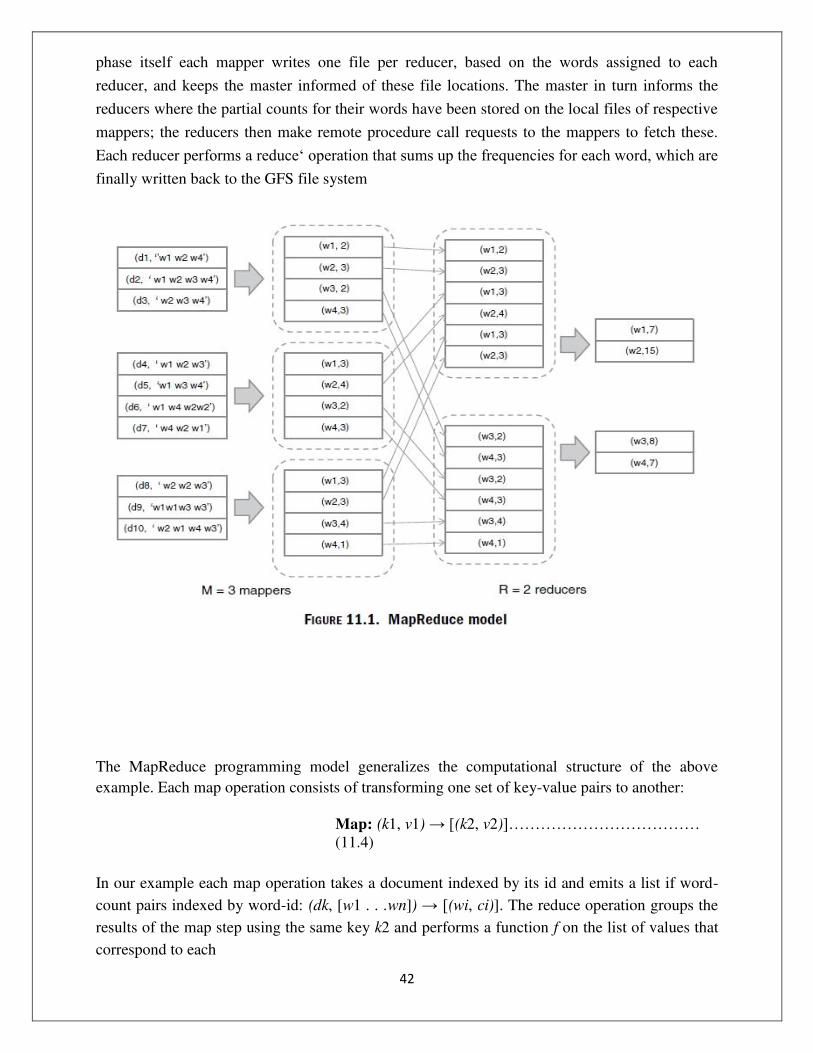
42
phase itself each mapper writes one file per reducer, based on the words assigned to each
reducer, and keeps the master informed of these file locations. The master in turn informs the
reducers where the partial counts for their words have been stored on the local files of respective
mappers; the reducers then make remote procedure call requests to the mappers to fetch these.
Each reducer performs a reduce‘ operation that sums up the frequencies for each word, which are finally written back to the GFS file system
The MapReduce programming model generalizes the computational structure of the above
example. Each map operation consists of transforming one set of key-value pairs to another:
Map: (k1, v1) → [(k2, v2)]……………………………… (11.4)
In our example each map operation takes a document indexed by its id and emits a list if word-
count pairs indexed by word-id: (dk, [w1 . . .wn]) → [(wi, ci)]. The reduce operation groups the
results of the map step using the same key k2 and performs a function f on the list of values that
correspond to each

43
Reduce: (k2, [v2]) → (k2, f ([v2]))………………………. (11.5)
In our example each reduce operation sums the frequency counts for each word:

44
The implementation also generalizes. Each mapper is assigned an input-key range (set of values
for k1) on which map operations need to be performed. The mapper writes results of its map
operations to its local disk in R partitions, each corresponding to the output-key range (values of
k2) assigned to a particular reducer, and informs the master of these locations. Next each reducer
fetches these pairs from the respective mappers and performs reduce operations for each key k2
assigned to it. If a processor fails during the execution, the master detects this through regular
heartbeat communications it maintains with each worker, wherein updates are also exchanged
regarding the status of tasks assigned to workers.
If a mapper fails, then the master reassigns the key-range designated to it to another
working node for re-execution. Note that re-execution is required even if the mapper had
completed some of its map operations, because the results were written to local disk rather than
the GFS. On the other hand if a reducer fails only its remaining tasks (values k2) are reassigned
to another node, since the completed tasks would already have been written to the GFS.
Finally, heartbeat failure detection can be fooled by a wounded task that has a heartbeat
but is making no progress: Therefore, the master also tracks the overall progress of the
computation and if results from the last few processors in either phase are excessively delayed,
these tasks are duplicated and assigned to processors who have already completed their work.
The master declares the task completed when any one of the duplicate workers complete.
Such a fault-tolerant implementation of the MapReduce model has been implemented and
is widely used within Google; more importantly from an enterprise perspective, it is also
available as an open source implementation through the Hadoop project along with the HDFS
distributed file system.
The MapReduce model is widely applicable to a number of parallel computations, including
database-oriented tasks which we cover later. Finally we describe one more example, that of
indexing a large collection of documents, or, for that matter any data including database records: The
map task consists of emitting a word-document/record id pair for each word: (dk, [w1 . . .wn]) → [(wi, dk)]. The reduce step groups the pairs by word and creates an index entry for each word: [(wi,
dk)] → (wi, [di1 . . . dim]).
Indexing large collections is not only important in web search, but also a critical aspect of
handling structured data; so it is important to know that it can be executed efficiently in parallel
using

45
MapReduce. Traditional parallel databases focus on rapid query execution against data
warehouses that are updated infrequently; as a result these systems often do not parallelize index
creation sufficiently well. Open in any Browser
Open in any Browser NameNode - http://localhost:50070/
Open in any Browser JobTracker - http://localhost:50030/
open hadoop/hadoop-1.2.1 create a document type something in that document and save
it as test.txt
bin/hadoop fs -ls /
Found 1 items drwxr-xr-x - vishal supergroup 0 2014-04-15 01:13 /tmp
bin/hadoop fs -mkdir example
bin/hadoop fs -ls /user/vishal/
Found 1 items drwxr-xr-x - vishal supergroup /user/vishal/example
bin/hadoop fs -copyFromLocal test.txt /user/vishal/example
bin/hadoop jar hadoop-examples-1.2.1.jar wordcount /user/vishal/example/test.txt /hello
(OR)

46
In Eclipse New
Java Project
Provide Project Name
Next
Select Libraries
Add
Externals JARs
Go to Hadoop
hadoop-1.2.1
select all jar files
again click on Add
External JARs
go to hadoop
hadoop-1.2.1
lib
select all JAR files
click on Finish.
Right Click on Src Folder
Select Class
Provide a Class name: WCE
Package name:
com.WordCount.Example
Click on Finish. package com.WordCount.Example;
import
java.io.IOException;
import java.util.*;
import
org.apache.hadoop.fs.Path;
import
org.apache.hadoop.conf.*;
import org.apache.hadoop.io.*;
import
org.apache.hadoop.mapred.*;
import org.apache.hadoop.util.*; public class WCE {
public static class Map extends MapReduceBase implements Mapper<LongWritable, Text,
Text, IntWritable> {
private final static IntWritable one = new
IntWritable(1); private Text word = new Text();
public void map(LongWritable key, Text value, OutputCollector<Text, IntWritable> output,
Reporter reporter) throws IOException {

47
String line = value.toString();
StringTokenizer tokenizer = new
StringTokenizer(line); While
(tokenizer.hasMoreTokens()) {
word.set(tokenizer.nextToken());
output.collect(word, one); } } }
public static class Reduce extends MapReduceBase implements Reducer<Text, IntWritable,
Text, IntWritable> {
public void reduce(Text key, Iterator<IntWritable> values, OutputCollector<Text,
IntWritable> output, Reporter reporter) throws IOException { int sum = 0; while (values.hasNext()) { sum += values.next().get(); } output.collect(key, new IntWritable(sum)); }}
public static void main(String[] args) throws Exception
{ JobConf conf = new JobConf(WCE.class); conf.setJobName("wordcount"); conf.setOutputKeyClass(Text.class);

48
conf.setOutputValueClass(IntWritable.class); conf.setMapperClass(Map.class); conf.setCombinerClass(Reduce.class);
conf.setReducerClass(Reduce.class);
FileInputFormat.addInputPath(conf, new Path(args[0]));
FileOutputFormat.setOutputPath(conf, new
Path(args[1])); JobClient.runJob(conf); }}
Right Click on Project Name
New
File
sample
type something in the sample file.
Right Click on Project Name
Export
Click on Java
JAR File
Provide a JAR File
Name
Select The Location where to save the JAR file.
Right Click on Project Name
Run as
Run Configuration
Java Application
new
In Main
WordCount
Click on Search and click on the JAR File which you have
created
Click on Arguments
Provide under Program arguments
sample output
Click on Run.
Right Click on Project Name
Refresh
An output file is created in your project.
Conclusion: Hence we have implemented Map Reduce example such as Word Count program on an file which will count the no.of times a word repeats in the given file.
*****

49
Class: BE(CSE) Subject: Lab I- Cloud Computing
Experiment No. 8
_______________________________________________________________ Aim: : Case Study: PAAS (Face book, Google App Engine)
Theory:
Platform-as-a-Service (PaaS):
Cloud computing has evolved to include platforms for building and running custom web-based
applications, a concept known as Platform-as-a- Service. PaaS is an outgrowth of the SaaS
application delivery model. The PaaS model makes all of the facilities required to support the
complete life cycle of building and delivering web applications and services entirely available
from the Internet, all with no software downloads or installation for developers, IT managers,
or end users. Unlike the IaaS model, where developers may create a specific operating system
instance with homegrown applications running, PaaS developers are concerned only with
webbased development and generally do not care what operating system is used. PaaS services
allow users to focus on innovation rather than complex infrastructure. Organizations can
redirect a significant portion of their budgets to creating applications that provide real business
value instead of worrying about all the infrastructure issues in a roll-your-own delivery model.
The PaaS model is thus driving a new era of mass innovation. Now, developers around the
world can access unlimited computing power. Anyone with an Internet connection can build
powerful applications and easily deploy them to users globally. Google App Engine:
Architecture :
The Google App Engine (GAE) is Google`s answer to the ongoing trend of Cloud Computing
offerings within the industry. In the traditional sense, GAE is a web application hosting
service, allowing for development and deployment of web-based applications within a pre-
defined runtime environment. Unlike other cloud-based hosting offerings such as Amazon
Web Services that operate on an IaaS level, the GAE already provides an application
infrastructure on the PaaS level. This means that the GAE
abstracts from the underlying hardware and operating system layers by providing the hosted
application with a set of application-oriented services. While this approach is very convenient for

50
developers of such applications, the rationale behind the GAE is its focus on scalability and
usage-based infrastructure as well as payment. Costs :
Developing and deploying applications for the GAE is generally free of charge but restricted to a
certain amount of traffic generated by the deployed application. Once this limit is reached within
a certain time period, the application stops working. However, this limit can be waived when
switching to a billable quota where the developer can enter a maximum budget that can be spent
on an application per day. Depending on the traffic, once the free quota is reached the application
will continue to work until the maximum budget for this day is reached. Table 1 summarizes
some of the in our opinion most important quotas and corresponding amount per unit that is
charged when free resources are depleted and additional, billable quota is desired. Features :
With a Runtime Environment, the Data store and the App Engine services, the GAE can be
divided into three parts. Runtime Environment
The GAE runtime environment presents itself as the place where the actual application is
executed. However, the application is only invoked once an HTTP request is processed to the
GAE via a web browser or some other interface, meaning that the application is not constantly
running if no invocation or processing has been done. In case of such an HTTP request, the
request handler forwards the request and the GAE selects one out of many possible Google
servers where the application is then instantly deployed and executed for a certain amount of
time (8). The application may then do some computing and return the result back to the GAE
request handler which forwards an HTTP response to the client. It is important to understand that
the application runs completely embedded in this described sandbox environment but only as
long as requests are still coming in or some processing is done within the application. The reason
for this is simple: Applications should only run when they are actually computing, otherwise
they would allocate precious computing power and memory without need. This paradigm shows
already the GAE‘s potential in terms of scalability. Being able to run multiple instances of one
application independently on different servers guarantees for a decent level of scalability.
However, this highly flexible and stateless application execution paradigm has its limitations.
Requests
are processed no longer than 30 seconds after which the response has to be returned to the client
and the application is removed from the runtime environment again (8). Obviously this method
51
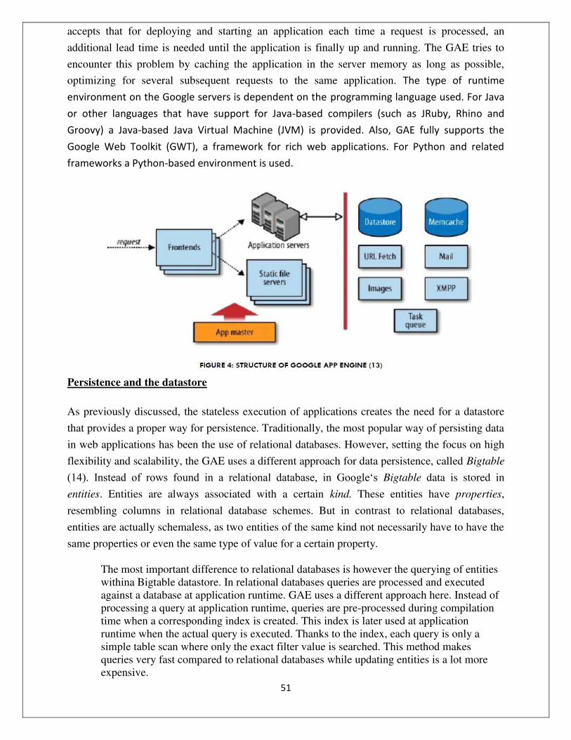
accepts that for deploying and starting an application each time a request is processed, an
additional lead time is needed until the application is finally up and running. The GAE tries to
encounter this problem by caching the application in the server memory as long as possible,
optimizing for several subsequent requests to the same application. The type of runtime
environment on the Google servers is dependent on the programming language used. For Java
or other languages that have support for Java-based compilers (such as JRuby, Rhino and
Groovy) a Java-based Java Virtual Machine (JVM) is provided. Also, GAE fully supports the
Google Web Toolkit (GWT), a framework for rich web applications. For Python and related
frameworks a Python-based environment is used.
Persistence and the datastore
As previously discussed, the stateless execution of applications creates the need for a datastore
that provides a proper way for persistence. Traditionally, the most popular way of persisting data
in web applications has been the use of relational databases. However, setting the focus on high
flexibility and scalability, the GAE uses a different approach for data persistence, called Bigtable
(14). Instead of rows found in a relational database, in Google‘s Bigtable data is stored in
entities. Entities are always associated with a certain kind. These entities have properties,
resembling columns in relational database schemes. But in contrast to relational databases,
entities are actually schemaless, as two entities of the same kind not necessarily have to have the
same properties or even the same type of value for a certain property.
The most important difference to relational databases is however the querying of entities withina Bigtable datastore. In relational databases queries are processed and executed against a database at application runtime. GAE uses a different approach here. Instead of processing a query at application runtime, queries are pre-processed during compilation time when a corresponding index is created. This index is later used at application runtime when the actual query is executed. Thanks to the index, each query is only a simple table scan where only the exact filter value is searched. This method makes queries very fast compared to relational databases while updating entities is a lot more expensive.

52
Transactions are similar to those in relational databases. Each transaction is atomic,
meaning that it either fully succeeds or fails. As described above, one of the advantages of the
GAE is its scalability through concurrent instances of the same application. But what happens
when two instances try to start transactions trying to alter the same entity? The answer to this is
quite simple: Only the first instance gets access to the entity and keeps it until the transaction is
completed or eventually failed. In this case the second instance will receive a concurrency failure
exception. The GAE uses a method of handling such parallel transactions called optimistic
concurrency control. It simply denies more than one altering transaction on an entity and
implicates that an application running within the GAE should have a mechanism trying to get
write access to an entity multiple times before finally giving up.
Heavily relying on indexes and optimistic concurrency control, the GAE allows
performing queries very fast even at higher scales while assuring data consistency. Services
As mentioned earlier, the GAE serves as an abstraction of the underlying hardware and operating
system layers. These abstractions are implemented as services that can be directly called from
the actual application. In fact, the datastore itself is as well a service that is controlled by the
runtime environment of the application. MEM CACHE
The platform innate memory cache service serves as a short-term storage. As its name suggests,
it stores data in a server‘s memory allowing for faster access compared to the datastore. Memcache is a non-persistent data store that should only be used to store temporary data within a
series of computations. Probably the most common use case for Memcache is to store session
specific data (15). Persisting session information in the datastore and executing queries on every
page interaction is highly inefficient over the application lifetime, since session-owner instances
are unique per session (16). Moreover, Memcache is well suited to speed up common datastore
queries (8). To interact with the Memcache GAE supports JCache, a proposed interface standard for memory caches (17). URL FETCH
Because the GAE restrictions do not allow opening sockets (18), a URL Fetch service can be
used to send HTTP or HTTPS requests to other servers on the Internet. This service works
asynchronously, giving the remote server some time to respond while the request handler can do

53
other things in the meantime. After the server has answered, the URL Fetch service returns
response code as well as header and body. Using the Google Secure Data Connector an
application can even access servers behind a company‘s firewall (8). MAIL
The GAE also offers a mail service that allows sending and receiving email messages. Mails can
be sent out directly from the application either on behalf of the application‘s administrator or on behalf of userswith Google Accounts. Moreover, an application can receive emails in the form of
HTTP requests initiated by the App Engine and posted to the app at multiple addresses. In
contrast to incoming emails, outgoing messages may also have an attachment up to 1 MB (8). XMPP
In analogy to the mail service a similar service exists for instant messaging, allowing an
application to send and receive instant messages when deployed to the GAE. The service allows
communication to and from any instant messaging service compatible to XMPP (8), a set of open
technologies for instant messaging and related tasks (19). IMAGES
Google also integrated a dedicated image manipulation service into the App Engine. Using this
service images can be resized, rotated, flipped or cropped (18). Additionally it is able to combine
several images into a single one, convert between several image formats and enhance
photographs. Of course the API also provides information about format, dimensions and a
histogram of color values (8). USERS
User authentication with GAE comes in two flavors. Developers can roll their own
authentication service using custom classes, tables and Memcache or simply plug into Google‘s Accounts service. Since for most applications the time and effort of creating a sign-up page and store user passwords is
not worth the trouble (18), the User service is a very convenient functionality which gives an
easy method for authenticating users within applications. As byproduct thousands of Google
Accounts are leveraged. The User service detects if a user has signed in and otherwise redirect
the user to a sign-in page. Furthermore, it can detect whether the current user is an administrator,
which facilitates implementing admin-only areas within the application (8).

54
OAUTH
The general idea behind OAuth is to allow a user to grant a third party limited permission to
access protected data without sharing username and password with the third party. The OAuth
specification separates between a consumer, which is the application that seeks permission on
accessing protected data, and the service provider who is storing protected data on his users'
behalf (20). Using Google Accounts and the GAE API, applications can be an OAuth service
provider (8). SCHEDULED TASKS AND TASK QUEUES
Because background processing is restricted on the GAE platform, Google introduced task
queues as another built-in functionality (18). When a client requests an application to do certain
steps, the application might not be able to process them right away. This is where the task queues
come into play. Requests that cannot be executed right away are saved in a task queue that
controls the correct sequence of execution. This way, the client gets a response to its request
right away, possibly with the indication that the request will be executed later (13). Similar to the
concept of task queues are corn jobs. Borrowed from the UNIX world, a GAE cron job is a
scheduled job that can invoke a request handler at a pre-specified time (8). BLOBSTORE
The general idea behind the blobstore is to allow applications to handle objects that are much
larger than the size allowed for objects in the datastore service. Blob is short for binary large
object and is designed to serve large files, such as video or high quality images. Although blobs
can have up to 2 GB they have to be processed in portions, one MB at a time. This restriction
was introduced to smooth the curve of datastore traffic. To enable queries for blobs, each has a
corresponding blob info record which is persisted in the datastore (8), e. g. for creating an image
database. ADMINISTRATION CONSOLE
The administration console acts as a management cockpit for GAE applications. It gives the
developer real-time data and information about the current performance of the deployed
application and is used to upload new versions of the source code. At this juncture it is possible
to test new versions of the
application and switch the versions presented to the user. Furthermore, access data and logfiles
can be viewed. It also enables analysis of traffic so that quota can be adapted when needed. Also

55
the status of scheduled tasks can be checked and the administrator is able to browse the
applications datastore and manage indices (8). App Engine for Business
While the GAE is more targeted towards independent developers in need for a hosting platform
for their medium-sized applications, Google`s recently launched App Engine for Business tries
to target the corporate market. Although technically mostly relying on the described GAE,
Google added some enterprise features and a new pricing scheme to make their cloud computing
platform more attractive for enterprise customers (21). Regarding the features, App Engine for
Business includes a central development manager that allows a central administration of all
applications deployed within one company including access control lists. In addition to that
Google now offers a 99.9% service level agreement as well as premium developer support.
Google also adjusted the pricing scheme for their corporate customers by offering a fixed price
of $8 per user per application, up to a maximum of $1000, per month. Interestingly, unlike the
pricing scheme for the GAE, this offer includes unlimited processing power for a fixed price of
$8 per user, application and month. From a technical point of view, Google tries to accommodate
for established industry standards, by now offering SQL database support in addition to the
existing Bigtable datastore described above (8). APPLICATION DEVELOPMENT USING GOOGLE APP ENGINE General Idea
In order to evaluate the flexibility and scalability of the GAE we tried to come up with an
application that relies heavily on scalability, i.e. collects large amounts of data from external
sources. That way we hoped to be able to test both persistency and the gathering of data from
external sources at large scale. Therefore our idea has been to develop an application that
connects people`s delicious bookmarks with their respective Facebook accounts. People using
our application should be able to see what their
Facebook friends‘ delicious bookmarks are, provided their Facebook friends have such a
delicious account. This way a user can get a visualization of his friends‘ latest topics by looking at a generated tag cloud giving him a clue about the most common and shared interests. PLATFORM AS A SERVICE: GOOGLE APP ENGINE:--
The Google cloud, called Google App Engine, is a ‗platform as a service‘ (PaaS) offering. In contrast with the Amazon infrastructure as a service cloud, where users explicitly provision
virtual machines and control them fully, including installing, compiling and running software on

56
them, a PaaS offering hides the actual execution environment from users. Instead, a software
platform is provided along with an SDK, using which users develop applications and deploy
them on the cloud. The PaaS platform is responsible for executing the applications, including
servicing external service requests, as well as running scheduled jobs included in the application.
By making the actual execution servers transparent to the user, a PaaS platform is able to share
application servers across users who need lower capacities, as well as automatically scale
resources allocated to applications that experience heavy loads. Figure 5.2 depicts a user view of
Google App Engine. Users upload code, in either Java or Python, along with related files, which
are stored on the Google File System, a very large scale fault tolerant and redundant storage
system. It is important to note that an application is immediately available on the internet as soon
as it is successfully uploaded (no virtual servers need to be explicitly provisioned as in IaaS).
Resource usage for an application is metered in terms of web requests served and CPU-
hours actually spent executing requests or batch jobs. Note that this is very different from the
IaaS model: A PaaS application can be deployed and made globally available 24×7, but charged
only when accessed
(or if batch jobs run); in contrast, in an IaaS model merely making an application continuously
available incurs the full cost of keeping at least some of the servers running all the time. Further,
deploying applications in Google App Engine is free, within usage limits; thus applications can
be developed and tried out free and begin to incur cost only when actually accessed by a
sufficient volume of requests. The PaaS model enables Google to provide such a free service
because applications do not run in

57
dedicated virtual machines; a deployed application that is not accessed merely consumes storage
for its code and data and expends no CPU cycles.
GAE applications are served by a large number of web servers in Google‘s data centers that execute requests from end-users across the globe. The web servers load code from the GFS
into memory and serve these requests. Each request to a particular application is served by any
one of GAE‘s web servers; there is no guarantee that the same server will serve requests to any two requests, even from the same HTTP session. Applications can also specify some functions to
be executed as batch jobs which are run by a scheduler. Google Datastore:--
Applications persist data in the Google Datastore, which is also (like Amazon SimpleDB) a non-
relational database. The Datastore allows applications to define structured types (called ‗kinds‘) and store their instances (called ‗entities‘) in a distributed manner on the GFS file system. While one can view Datastore ‗kinds‘ as table structures and entities as records, there are important differences between a relational model and the Datastore, some of which are also illustrated in
Figure 5.3.
Unlike a relational schema where all rows in a table have the same set of columns, all entities of a
‗kind‘ need not have the same properties. Instead, additional properties can be added to any entity. This feature is particularly useful in situations where one cannot foresee all the potential properties in

58
a model, especially those that occur occasionally for only a small subset of records. For example, a
model storing
‗products‘ of different types (shows, books, etc.) would need to allow each product to have a
different set of features. In a relational model, this would probably be implemented using a
separate FEATURES table, as shown on the bottom left of Figure 5.3. Using the Datastore, this
table (‗kind‘) is not required; instead, each product entity can be assigned a different set of
properties at runtime. The Datastore allows simple queries with conditions, such as the first
query shown in Figure 5.3 to retrieve all customers having names in some lexicographic range.
The query syntax (called GQL) is essentially the same as SQL, but with some restrictions. For
example, all inequality conditions in a querymust be on a single property; so a query that also
filtered customers on, say, their ‗type‘, would be illegal in GQL but allowed in SQL.
Relationships between tables in a relational model are modeled using foreign keys. Thus,
each account in the ACCTS table has a pointer ckey to the customer in the CUSTS table that it
belongs to. Relationships are traversed via queries using foreign keys, such as retrieving all
accounts for a particular customer, as shown. The Datastore provides a more object-oriented
approach to relationships in persistent data. Model definitions can include references to other
models; thus each entity of the Accts
‗kind‘ includes a reference to its customer, which is an entity of the Custs ‗kind.‘ Further, relationships defined by such references can be traversed in both directions, so not only can one
directly access the customer of an account, but also all accounts of a given customer, without
executing any query operation, as shown in the figure.
GQL queries cannot execute joins between models. Joins are critical when using SQL to
efficiently retrieve data from multiple tables. For example, the query shown in the figure
retrieves details of all products bought by a particular customer, for which it needs to join data
from the transactions (TXNS), products (PRODS) and product features (FEATURES) tables.
Even though GQL does not allow joins, its ability to traverse associations between entities often
enables joins to be avoided, as shown in the figure for the above example: By storing references
to customers and products in the Txns model, it is possible to retrieve all transactions for a given
customer through a reverse traversal of the customer reference. The product references in each
transaction then yield all products and their features (as discussed earlier, a separate Features
model is not required because of schema
flexibility). It is important to note that while object relationship traversal can be used as an
alternative to joins, this is not always possible, and when required joins may need to be explicitly
executed by application code.

59
The Google Datastore is a distributed object store where objects (entities) of all GAE
applications are maintained using a large number of servers and the GFS distributed file system.
From a user perspective, it is important to ensure that in spite of sharing a distributed storage
scheme with many other users, application data is (a) retrieved efficiently and (b) atomically
updated. The Datastore provides a mechanism to group entities from different ‗kinds‘ in a hierarchy that is used for both these purposes. Notice that in Figure 5.3entities of the Accts and
Txns ‗kinds‘ are instantiated with a parameter ‗parent‘ that specifies a particular customer entity, thereby linking these three entities in an ‗entity group‘. The Datastore ensures that all entities belonging to a particular group are stored close together in the distributed file system (we
shall see how in Chapter 10). The Datastore allows processing steps to be grouped into
transactions wherein updates to data are guaranteed to be
atomic; however this also requires that each transaction only manipulates entities belonging to
the same entity group. While this transaction model suffices for most on line applications,
complex batch updates that update many unrelated entities cannot execute atomically, unlike in a
relational database where there are no such restrictions. Amazon SimpleDB:-- Amazon SimpleDB is also a nonrelational database, in many ways similar to the Google Datastore.
SimpleDB‗domains‘ correspond to ‗kinds‘, and ‗items‘ to entities; each item can have a number of attribute-value pairs, and different items in a domain can have different sets of attributes,
similar to Datastore entities. Queries on SimpleDB domains can include conditions, including
inequality conditions, on any number of attributes. Further, just as in the Google Datastore, joins
are not permitted. However, SimpleDB does not support object relationships as in Google
Datastore, nor does it support transactions. It is important to note that all data in SimpleDB is
replicated for redundancy, just as in
GFS. Because of replication, SimpleDB features an ‗eventual consistency‘ model, wherein data is guaranteed to be propagated to at least one replica and will eventually reach all replicas, albeit
with some delay. This can result in perceived inconsistency, since an immediate read following a
write may not always yield the result written. In the case of Google Datastore on the other hand,
writes succeed only when all replicas are updated; this avoids inconsistency but also makes
writes slower. PAAS CASE STUDY: FACEBOOK

60
Facebook provides some PaaS capabilities to application developers:--
Web services remote APIs that allow access to social network properties, data,Like button,
etc.
Many third-parties run their apps off Amazon EC2, and interface to Facebook via its APIs PaaS
IaaS
Facebook itself makes heavy use of PaaS services for their own private cloud
Key problems: how to analyze logs, make suggestions, determine which ads to place.
Facebook API: Overview:--
What you can do:
Read data from profiles and pages
Navigate the graph (e.g., via friends lists)
Issue queries (for posts, people, pages, ...)
Facebook API: The Graph API :
{
"id": "1074724712", "age_range": {
"min": 21
},
"locale": "en_US", "location": {
"id": "101881036520836",
"name": "Philadelphia,
Pennsylvania" }

61
}
Requests are mapped directly to HTTP:
https://graph.facebook.com/(identifier)?fields=(fieldList)
Response is in JSON
Uses several HTTP methods: GET for reading
POST for adding or modifying
DELETE for removing
IDs can be numeric or names
/1074724712 or /andreas.haeberlen
Pages also have IDs
Authorization is via 'access tokens'
Opaque string; encodes specific permissions (access user location, but not interests, etc.)
Has an expiration date, so may need to be refreshed

62
Facebook Data Management / Warehousing Tasks
Main tasks for “cloud” infrastructure: Summarization (daily, hourly)
to help guide development on different components
to report on ad performance
recommendations
Ad hoc analysis:
Answer questions on historical data – to help with managerial decisions
Archival of logs
Spam detection
Ad optimization
Initially used Oracle DBMS for this
But eventually hit scalability, cost, performance bottlenecks just like Salesforce does now

63
Data Warehousing at Facebook:
PAAS AT FACEBOOK:
Scribe – open source logging, actually records the data that will be analyzed by Hadoop
Hadoop (MapReduce – discussed next time) as batch processing engine for data analysis
As of 2009: 2nd largest Hadoop cluster in the world, 2400 cores, > 2PB data with > 10TB added every day
Hive – SQL over Hadoop, used to write the data analysis queries
Federated MySQL, Oracle – multi-machine DBMSs to store query results
Example Use Case 1: Ad Details
Advertisers need to see how their ads are performing
Cost-per-click (CPC), cost-per-1000-impressions (CPM)
Social ads – include info from friends
Engagement ads – interactive with video
Performance numbers given:
Number unique users, clicks, video views, …
Main axes:

64
Account, campaign, ad
Time period
Type of interaction
Users
Summaries are computed using Hadoop via Hive
Use Case 2: Ad Hoc analysis, feedback
Engineers, product managers may need to understand what is going on
e.g., impact of a new change on some sub-population
Again, Hive-based, i.e., queries are in SQL with database joins
Combine data from several tables, e.g., click-through rate = views combined with clicks
Sometimes requires custom analysis code with sampling
CONCLUSION :
Cloud Computing remains the number one hype topic within the IT industry at present. Our
evaluation of the Google App Engine and facebook has shown both functionality and limitations
of the platform. Developing and deploying an application within the GAE is in fact quite easy
and in a way shows the progress that software development and deployment has made. Within
our application we were able to use the abstractions provided by the GAE without problems,
although the concept of Bigtable requires a big change in mindset when developing. Our
scalability testing showed the limitations of the GAE at this point in time. Although being an
extremely helpful feature and a great USP for the GAE, the built-in scalability of the GAE
suffers from both purposely-set as well as technical restrictions at the moment. Coming back to
our motivation of evaluating the GAE in terms of its sufficiency for serious large-scale
applications in a professional environment, we have to conclude that the GAE not (yet) fulfills
business needs for enterprise applications at present.
*****

65
Class: BE(CSE) Subject: Lab I- Cloud Computing
Experiment No. 9
_______________________________________________________________
Aim: AWS Case Study: Amazon.com.
Theory: About AWS
Launched in 2006, Amazon Web Services (AWS) began exposing key infrastructure
services to businesses in the form of web services -- now widely known as cloud computing.
The ultimate benefit of cloud computing, and AWS, is the ability to leverage a new business
model and turn capital infrastructure expenses into variable costs.
Businesses no longer need to plan and procure servers and other IT resources weeks or
months inadvance.
Using AWS, businesses can take advantage of Amazon's expertise and economies of scale
to access resources when their business needs them, delivering results faster and at a lower cost.
Today, Amazon Web Services provides a highly reliable, scalable, low-cost infrastructure
platform in the cloud that powers hundreds of thousands of businesses in 190 countries around the world.
Amazon.com is the world‘s largest online retailer. In 2011, Amazon.com switched from tape backup to using Amazon Simple Storage Service (Amazon S3) for backing up the majority of its
Oracle databases. This strategy reduces complexity and capital expenditures, provides
faster backup and restore performance, eliminates tape capacity planning for backup
and archive, and frees up administrative staff for higher value operations. The company
was able to replace their backup tape infrastructure with cloud-based Amazon S3
storage, eliminate backup software, and experienced a 12X performance improvement,
reducing restore time from around 15 hours to 2.5 hours in select scenarios.

66
With data center locations in the U.S., Europe, Singapore, and Japan, customers across all
industries are taking advantage of the following benefits:
Low Cos
Agility and Instant Elasticity
Open and Flexible
Secure
The Challenge
As Amazon.com grows larger, the sizes of their Oracle databases continue to grow, and so does
the sheer number of databases they maintain. This has caused growing pains related to backing
up legacy Oracle databases to tape and led to the consideration of alternate strategies including
the use of Cloud services of Amazon Web Services (AWS), a subsidiary of Amazon.com. Some
of the business challenges Amazon.com faced included:
Utilization and capacity planning is complex, and time and capital expense budget are at a
premium. Significant capital expenditures were required over the years for tape hardware,
data center space for this hardware, and enterprise licensing fees for tape software. During
that time, managing tape infrastructure required highly skilled staff to spend time with setup,
certification and engineering archive planning instead of on higher value projects. And at the
end of every fiscal year, projecting future capacity requirements required time consuming
audits, forecasting, and budgeting.
The cost of backup software required to support multiple tape devices sneaks up on you.
Tape robots provide basic read/write capability, but in order to fully utilize them, you must
invest in proprietary tape backup software. For Amazon.com, the cost of the software had
been high, and added significantly to overall backup costs. The cost of this software was an
ongoing budgeting pain point, but one that was difficult to address as long as backups needed
to be written to tape devices.
67
Maintaining reliable backups and being fast and efficient when retrieving data requires a lot
of time and effort with tape. When data needs to be durably stored on tape, multiple copies
are required. When everything is working correctly, and there is minimal contention for tape
resources, the tape robots and backup software can easily find the required data. However, if
there is a hardware failure, human intervention is necessary to restore from tape. Contention
for tape drives resulting from multiple users‘ tape requests slows down restore processes even more. This adds to the recovery time objective (RTO) and makes achieving it more
challenging compared to backing up to Cloud storage.
Why Amazon Web Services?
Amazon.com initiated the evaluation of Amazon S3 for economic and performance
improvements related to data backup. As part of that evaluation, they considered security,
availability, and performance aspects of Amazon S3 backups. Amazon.com also executed a
cost-benefit analysis to ensure that a migration to Amazon S3 would be financially worthwhile.
That cost benefit analysis included the following elements:
Performance advantage and cost competitiveness. It was important that the overall costs of
the backups did not increase. At the same time, Amazon.com required faster backup and
recovery performance. The time and effort required for backup and for recovery operations
proved to be a significant improvement over tape, with restoring from Amazon S3 running
from two to twelve times faster than a similar restore from tape. Amazon.com required any
new backup medium to provide improved performance while maintaining or reducing overall
costs. Backing up to on-premises disk based storage would have improved performance, but
missed on cost competitiveness. Amazon S3 Cloud based storage met both criteria.
Greater durability and availability. Amazon S3 is designed to provide 99.999999999%
durability and 99.99% availability of objects over a given year. Amazon.com compared these
figures with those observed from their tape infrastructure, and determined that Amazon S3
offered significant improvement.
Less operational friction. Amazon.com DBAs had to evaluate whether Amazon S3 backups
would be viable for their database backups. They determined that using Amazon S3 for
backups was easy to implement because it worked seamlessly with Oracle RMAN.

68
Strong data security. Amazon.com found that AWS met all of their requirements for physical
security, security accreditations, and security processes, protecting data in flight, data at rest,
and utilizing suitable encryption standards.
The Benefits With the migration to Amazon S3 well along the way to completion, Amazon.com has realized several
benefits, including:
Elimination of complex and time-consuming tape capacity planning. Amazon.com is
growing larger
and more dynamic each year, both organically and as a result of acquisitions. AWS has
enabled Amazon.com to keep pace with this rapid expansion, and to do so seamlessly.
Historically, Amazon.com business groups have had to write annual backup plans,
quantifying the amount of tape storage that they plan to use for the year and the frequency
with which they will use the tape resources. These plans are then used to charge each
organization for their tape usage, spreading the cost among many teams. With Amazon S3,
teams simply pay for what they use, and are billed for their usage as they go. There are
virtually no upper limits as to how much data can be stored in Amazon S3, and so there are
no worries about running out of resources. For teams adopting Amazon S3 backups, the need
for formal planning has been all but eliminated.
Reduced capital expenditures. Amazon.com no longer needs to acquire tape robots, tape
drives, tape inventory, data center space, networking gear, enterprise backup software, or
predict future tape consumption. This eliminates the burden of budgeting for capital
equipment well in advance as well as the capital expense.
Immediate availability of data for restoring – no need to locate or retrieve physical tapes.
Whenever a DBA needs to restore data from tape, they face delays. The tape backup software
needs to read the tape catalog to find the correct files to restore, locate the correct tape, mount
the tape, and read the data from it. In almost all cases the data is spread across multiple tapes,
resulting in further delays. This, combined with contention for tape drives resulting from
multiple users‘ tape requests, slows the process down even more. This is especially severe during critical events such as a data center outage, when many databases must be restored
simultaneously and as soon as possible. None of these problems occur with Amazon S3. Data
restores can begin immediately, with no waiting or tape queuing – and that means the
database can be recovered much faster.

69
Backing up a database to Amazon S3 can be two to twelve times faster than with tape drives.
As one example, in a benchmark test a DBA was able to restore 3.8 terabytes in 2.5 hours
over gigabit Ethernet. This amounts to 25 gigabytes per minute, or 422MB per second. In
addition, since Amazon.com uses RMAN data compression, the effective restore rate was
3.37 gigabytes per second. This 2.5 hours compares to, conservatively, 10-15 hours that
would be required to restore from tape.
Easy implementation of Oracle RMAN backups to Amazon S3. The DBAs found it easy to
start backing up their databases to Amazon S3. Directing Oracle RMAN backups to Amazon
S3 requires
only a configuration of the Oracle Secure Backup Cloud (SBC) module. The effort required
to configure the Oracle SBC module amounted to an hour or less per database. After this one-
time setup, the database backups were transparently redirected to Amazon S3.
Durable data storage provided by Amazon S3, which is designed for 11 nines durability. On
occasion, Amazon.com has experienced hardware failures with tape infrastructure – tapes
that break, tape drives that fail, and robotic components that fail. Sometimes this happens
when a DBA is trying to restore a database, and dramatically increases the mean time to
recover (MTTR). With the durability and availability of Amazon S3, these issues are no
longer a concern.
Freeing up valuable human resources. With tape infrastructure, Amazon.com had to seek out
engineers who were experienced with very large tape backup installations – a specialized,
vendor-specific skill set that is difficult to find. They also needed to hire data center
technicians and dedicate them to problem-solving and troubleshooting hardware issues –
replacing drives, shuffling tapes around, shipping and tracking tapes, and so on. Amazon S3
allowed them to free up these specialists from day-to-day operations so that they can work on
more valuable, business-critical engineering tasks.
Elimination of physical tape transport to off-site location. Any company that has been storing
Oracle backup data offsite should take a hard look at the costs involved in transporting,
securing and storing
their tapes offsite – these costs can be reduced or possibly eliminated by storing the data in
Amazon S3.
As the world‘s largest online retailer, Amazon.com continuously innovates in order to provide improved customer experience and offer products at the lowest possible prices. One such
innovation has been to replace tape with Amazon S3 storage for database backups. This

70
innovation is one that can be easily replicated by other organizations that back up their Oracle
databases to tape. Products & Services
Compute
Content Delivery
Database
Deployment & Management
E-Commerce
Messaging
Monitoring
Networking
Payments & Billing
Storage
Support
Web Traffic
Workforce

71
Products & Services Compute
›Amazon Elastic Compute Cloud (EC2)
Amazon Elastic Compute Cloud delivers scalable, pay-as-you-go compute capacity in the cloud.
›Amazon Elastic MapReduce
Amazon Elastic MapReduce is a web service that enables businesses, researchers, data analysts, and developers to easily and cost-effectively process vast amounts of data.
›Auto Scaling
Auto Scaling allows to automatically scale our Amazon EC2capacity up or down according to conditions we define.
Content Delivery
›Amazon CloudFront
Amazon CloudFront is a web service that makes it easy to distribute content with low latency via a global network of edge locations.
Database
›Amazon SimpleDB
Amazon SimpleDB works in conjunction with Amazon S3 and AmazonEC2 to run queries on structured data in real time.

72
›Amazon Relational Database Service (RDS)
Amazon Relational Database Service is a web service that makes it easy to set up, operate, and scale a relational database in the cloud.
›Amazon ElastiCache
Amazon ElastiCache is a web service that makes it easy to deploy, operate, and scale an in-memory cache in the cloud.
E-Commerce
›Amazon Fulfillment Web Service (FWS)
Amazon Fulfillment Web Service allows merchants to deliver products using Amazon.com‘s worldwide fulfillment capabilities.
Deployment & Management
:AWS Elastic Beanstalk
AWS Elastic Beanstalk is an even easier way to quickly deploy and manage applications in
the AWS cloud. We simply upload our application, and Elastic Beanstalk automatically handles the deployment details of capacity provisioning, load balancing, auto-scaling, and application health monitoring.
›AWS CloudFormation
AWS CloudFormation is a service that gives developers and businesses an easy way to create a collection of related AWS resources and provision them in an orderly and predictable fashion.

73
Monitoring
›Amazon CloudWatch
Amazon CloudWatch is a web service that provides monitoring for AWS cloud resources, starting with Amazon EC2
Messaging
›Amazon Simple Queue Service (SQS)
Amazon Simple Queue Service provides a hosted queue for storing messages as they travel between computers, making it easy to build automated workflow between Web services.
›Amazon Simple Notification Service (SNS)
Amazon Simple Notification Service is a web service that makes it easy to set up, operate, and send notifications from the cloud.
›Amazon Simple Email Service (SES)
Amazon Simple Email Service is a highly scalable and cost-effective bulk and transactional email-sending service for the cloud.
Workforce
›Amazon Mechanical Turk
Amazon Mechanical Turk enables companies to access thousands of global workers on demand and programmatically integrate their work into various business processes.
Networking
›Amazon Route 53

74
Amazon Route 53 is a highly available and scalable Domain Name System (DNS) web service.
›Amazon Virtual Private Cloud (VPC)
Amazon Virtual Private Cloud (Amazon VPC) lets you provision a private, isolated section of the Amazon Web Services (AWS) Cloud where we can launch AWS resources in a virtual
network that you define. With Amazon VPC, we can define a virtual network topology that
closely resembles a traditional network that you might operate in your own datacenter.
›AWS Direct Connect
AWS Direct Connect makes it easy to establish a dedicated network connection from your premise to AWS, which in many cases can reduce our network costs, increase bandwidth
throughput, and provide a more consistent network experience than Internet-based connections.
›Elastic Load Balancing
Elastic Load Balancing automatically distributes incoming application traffic across multiple Amazon EC2 instances.
Payments & Billing
›Amazon Flexible Payments Service (FPS)
Amazon Flexible Payments Service facilitates the digital transfer of money between any two entities, humans or computers.
›Amazon DevPay

75
Amazon DevPay is a billing and account management service which enables developers to collect payment for their AWS applications.
Storage
›Amazon Simple Storage Service (S3)
Amazon Simple Storage Service provides a fully redundant data storage infrastructure for storing and retrieving any amount of data, at any time, from anywhere on the Web.
›Amazon Elastic Block Store (EBS)
Amazon Elastic Block Store provides block level storage volumes for use with
Amazon EC2 instances. Amazon EBS volumes are off-instance storage that persists
independently from the life of an instance.
›AWS Import/Export
AWS Import/Export accelerates moving large amounts of data into and out of AWS using
portable storage devices for transport.
Support
›AWS Premium Support AWS Premium Support is a one-on-one, fast-response support channel to help you build and run applications on AWS Infrastructure Services.
Web Traffic
›Alexa Web Information Service

76
Alexa Web Information Service makes Alexa‘s huge repository of data about structure and traffic patterns on the Web available to developers.
›Alexa Top Sites
Alexa Top Sites exposes global website traffic data as it is continuously collected and updated by Alexa Traffic Rank.
Amazon CloudFront
Amazon CloudFront is a web service for content delivery.
It integrates with other Amazon Web Services to give developers and businesses an easy
way to distribute content to end users with low latency, high data transfer speeds, and no
commitments.
Amazon CloudFront delivers our static and streaming content using a global network of
edge locations.
Requests for our objects are automatically routed to the nearest edge location, so content
is delivered with the best possible performance.
Amazon CloudFront
Amazon CloudFront is optimized to work with other Amazon Web Services, like Amazon
Simple Storage Service (S3) and Amazon Elastic Compute Cloud (EC2).
Amazon CloudFront also works seamlessly with any origin server, which stores the
original, definitive versions of our files.

77
Like other Amazon Web Services, there are no contracts or monthly commitments for
using Amazon CloudFront _ we pay only for as much or as little content as you actually deliver
through the service.
Amazon Simple Queue Service (Amazon SQS)
Amazon Simple Queue Service (Amazon SQS) offers a reliable, highly scalable, hosted
queue for storing messages as they travel between computers.
By using Amazon SQS, developers can simply move data between distributed
components of their applications that perform different tasks, without losing messages or requiring each
component to be always available.
Amazon SQS makes it easy to build an automated workflow, working in close
conjunction with the Amazon Elastic Compute Cloud (Amazon EC2) and the other AWS infrastructure web
services.
Amazon Simple Queue Service (Amazon SQS)
Amazon SQS works by exposing Amazon_s web-scale messaging infrastructure as a web
service.
Any computer on the Internet can add or read messages without any installed software or
special firewall configurations.
Components of applications using Amazon SQS can run independently, and do not need
to be on the same network, developed with the same technologies, or running at the same time
BigTable

78
Bigtable is a distributed storage system for managing structured data that is designed to
scale to a very large size: petabytes of data across thousands of commodity servers.
Many projects at Google store data in Bigtable, including web indexing, Google Earth,
and Google Finance.
These applications place very different demands on Bigtable, both in terms of data size
(from URLs to web pages to satellite imagery) and latency requirements (from backend bulk
processing to real-time data serving).
Despite these varied demands, Bigtable has successfully provided a fexible, high-
performance solution for all of these Google products.
The Google File System(GFS)
The Google File System (GFS) is designed to meet the rapidly growing demands of
Google_s data processing needs.
GFS shares many of the same goals as previous distributed file systems such as
performance, scalability, reliability, and availability.
It provides fault tolerance while running on inexpensive commodity hardware, and it
delivers high aggregate performance to a large number of clients.
While sharing many of the same goals as previous distributed file systems, file system
has successfully met our storage needs.
It is widely deployed within Google as the storage platform for the generation and
processing of data used by our service as well as research and development efforts that require large data sets.

79
The largest cluster to date provides hundreds of terabytes of storage across thousands
of disks on over a thousand machines, and it is concurrently accessed by hundreds of clients.
Conclusion: Thus we have studied a case study on amazon web services.
*****