department of computer science & …csempmslnotes2013.pdf · figure 1.1 shows the block diagram...
TRANSCRIPT

MICROPROCESSOR AND MULTICORE SYSTEMS
DEPARTMENT OF COMPUTER SCIENCE & ENGINEERING
SHRI VISHNU ENGINEERING COLLEGE FOR WOMEN
(Approved by AICTE, Accredited by NBA, Affiliated to JNTU Kakinada)
BHIMAVARAM – 534 202
1
UNIT-I overview of microcomputer structure and operation,execution of a three instruction program
microprocessor evolution and types, the 8086 micro processor family , 8086 internal architecture
, introduction to programming the 8086,8086 family assembly language programming :Program
development steps ,constructing the machine codes for 8086 instructions,writing programs for
use with an assembler, assembly language program development tools
1.1 OVERVIEW OF MICROCOMPUTER STRUCTURE AND OPERATION:
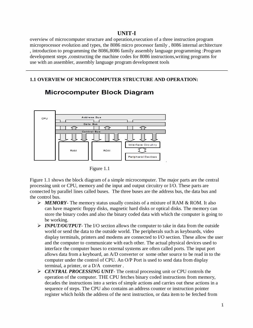
Figure 1.1
Figure 1.1 shows the block diagram of a simple microcomputer. The major parts are the central
processing unit or CPU, memory and the input and output circuitry or I/O. These parts are
connected by parallel lines called buses. The three buses are the address bus, the data bus and
the control bus.
MEMORY- The memory status usually consists of a mixture of RAM & ROM. It also
can have magnetic floppy disks, magnetic hard disks or optical disks. The memory can
store the binary codes and also the binary coded data with which the computer is going to
be working.
INPUT/OUTPUT- The I/O section allows the computer to take in data from the outside
world or send the data to the outside world. The peripherals such as keyboards, video
display terminals, printers and modems are connected to I/O section. These allow the user
and the computer to communicate with each other. The actual physical devices used to
interface the computer buses to external systems are often called ports. The input port
allows data from a keyboard, an A/D converter or some other source to be read in to the
computer under the control of CPU. An O/P Port is used to send data from display
terminal, a printer, or a D/A converter .
CENTRAL PROCESSING UNIT- The central processing unit or CPU controls the
operation of the computer. THE CPU fetches binary coded instructions from memory,
decades the instructions into a series of simple actions and carries out these actions in a
sequence of steps. The CPU also contains an address counter or instruction pointer
register which holds the address of the next instruction, or data item to be fetched from

2
memory. General purpose registers(GPRs) which are used for temporary storage of
binary data and circuitry which generates the control bus signals.
ADDRESS BUS- The address bus consists of 16,20,24,32 parallel signal lines. On these
lines the CPU sends out the address of the memory location. If the CPU has N address
lines then it can directly address 2N memory locations.
DATA BUS- The data bus consists of 8, 16, or 32 parallel signal lines. The double ended
arrows on the data bus means that the CPU can read data in from memory or from a port
on these lines, or it can send data out to memory or to a port on these lines.
CONTROL BUS- The control bus consists of 4 to 10 parallel signal lines. The CPU
sends out signals on the control bus to enable the outputs of addressed memory devices or
port devices. Typical control bus signals are memory read, memory write, I/O read, and
I/O write. To read a byte of data from a memory location, the CPU sends out the memory
address of the desired byte on the address bus and then sends out the memory read signal
on the control bus. The memory read signal enables the address memory device to output
a data word on to the data bus. The data word from the memory travels along the data bus
to the CPU.
1.2 MICROPROCESSOR EVOLUTION AND TYPES
A common way of categorizing microprocessors is by the number of bits that their ALU can
work with at a time. Microprocessor with a 4-bit ALU will be referred to asa 4-bit
microprocessor, regardless of the number of address lines or the number of data lines that it has.
The first commercially available MP was the Intel 4004, produced in 1971. It contained 2300
PMOS transistors.
In 1972 Intel came out with the 8008, which was capable of working with 8-bit words. Along
with this it required 20 more devices to work as CPU.
In 1974, Intel came out with the 8080 which had a much larger instruction set than 8008 and
required only two additional devices to form functional CPU.
Soon after this Motorola came out with MC6800, another 8-bit general purpose CPU. It required
only +5V. For many years they were the most sold MPs.
The other types of MPs are dedicated and embedded controllers, bit-slice processors and General
purpose CPUs.The 8085 & 8086 come under the general purpose CPUs.
1.3 THE MICROPROCESSOR FAMILY –OVERVIEW
The Intel 8086 is a 16-bit MP that works as a CPU in a microcomputer. The term 16-bit
means that it’s ALU, its internal registers, and most of its instructions are designed to work with
16-bit binary words. The 8086 has 16-bit data bus, so it can read data from or write data to
memory and ports either16 bits or 8 bits at a time. The 8086 has a 20-bit address bus, so it can
address any one of 220
, or 1,048,576, memory locations. Sixteen bit words will be stored in two
consecutive memory locations. If the first byte if the word is at an even address, the 8086 can
read the entire word in one operation. If the first byte of the word is at an odd address, the 8086
will read the first byte with one bus operation and the second byte with another bus operation.
The 8088 has the same ALU, the same registers, and the same instruction set as
8086. The 8088 has a 20 bit address bus, so it can address any one of 1,048,576
bytes in memory. The 8088 has 8 bit data bus so it can only read data from or
write data to memory and ports, 8 bits at a time.
The Intel 80186 is an improved version of the 8086 and 80188 is the improved
version of 8088. In addition to the 16 bit CPU 80186 and 80188 has
programmable peripheral devices integrated in the same package.
3
The Intel 80286 is a 16 bit ,advanced version of the 8086 which is specifically
designed for use as a CPU in a multiuser or multitasking microcomputer.80286
works as fast as 8086 and most programs written for 8086 can run for 80286.
With the 80386 processor, Intel started the 32 bit processor architecture, known
as the IA-32 architecture. This architecture extended all the address and general
purpose registers to 32 bits, which gave the processor the capability to handle 32
bit address, with 32 bit data. The Intel 80486 is the next member of the IA-32
architecture. This processor has the floating point processor integrated into CPU
itself.
1.4 8086 INTERNAL ARCHITECTURE
1.4.1 Architecture of 8086
Unlike microcontrollers, microprocessors do not have inbuilt memory. Mostly Princeton
architecture is used for microprocessors where data and program memory are combined in a single
memory interface. Since a microprocessor does not have any inbuilt peripheral, the circuit is
purely digital and the clock speed can be anywhere from a few MHZ to a few hundred MHZ or
even GHZ. This increased clock speed facilitates intensive computation that a microprocessor is
supposed to do.
We will discuss the basic architecture of Intel 8086 before discussing more advanced
microprocessor architectures.
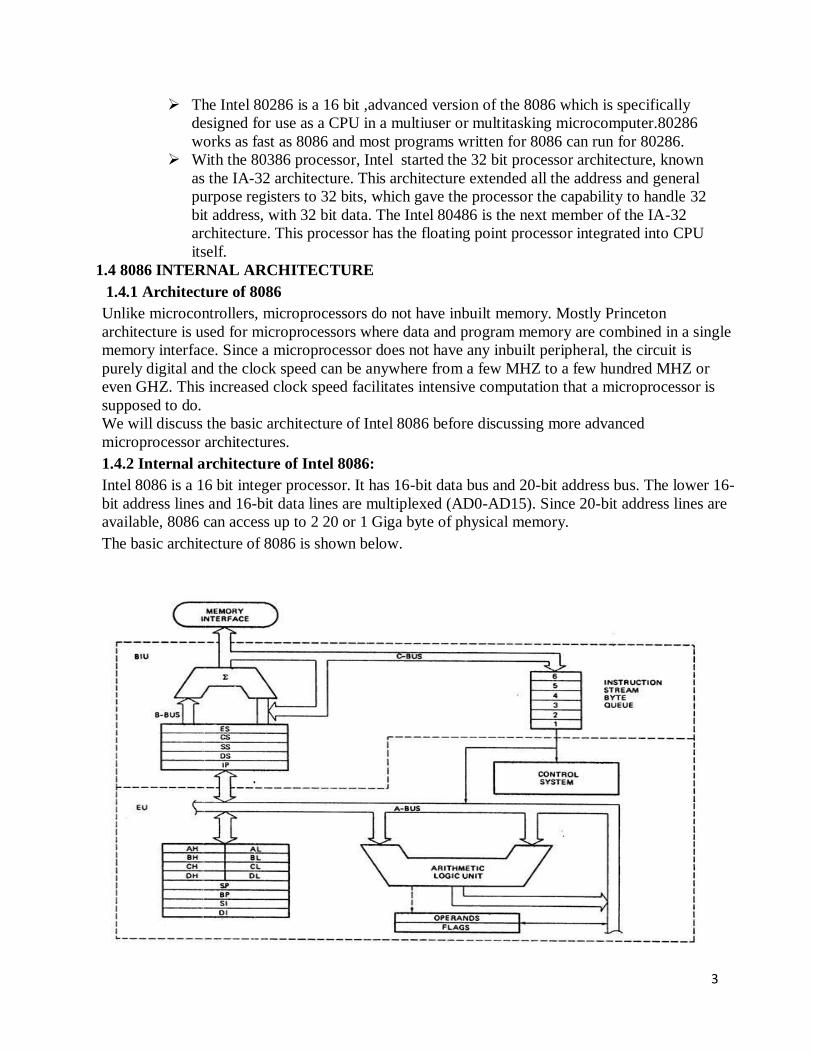
1.4.2 Internal architecture of Intel 8086:
Intel 8086 is a 16 bit integer processor. It has 16-bit data bus and 20-bit address bus. The lower 16-
bit address lines and 16-bit data lines are multiplexed (AD0-AD15). Since 20-bit address lines are
available, 8086 can access up to 2 20 or 1 Giga byte of physical memory.
The basic architecture of 8086 is shown below.

4
1.4.3 the execution unit
The execution unit of the 8086 tells the BIU where to fetch instructions or data from, decades
instructions, and executes instructions. It consists of control circuitry, instruction decoder and
ALU. The control circuitry directs internal operations. A decoder in the EU translates
instructions fetched from memory in to a se4ries of actions which the EU carries out. The EU has
a 16-bit ALU which can add, subtract, AND, OR, XOR, increment, decrement, complement, or
shift binary numbers.
Flag Register- A flag is a flip-flop that indicates some condition produced by the execution of an
instruction or controls certain operation of EU. A 16-bit flag register contains nine active flags.
Fig shows the location of nine flags in the flag register. Six of the nine flags are used to indicate
some condition produced by an instruction.
The six conditional flags in this group are the carry flag(CF), the parity flag(PF), the auxillary
flag(AF), the zero flag(ZF), the sign flag(SF), and the overflow flag(OF).
The three other flags in the flag register are used to control certain operations of the processor.
The six conditional flags are set or reset by the EU on the basis of the results of some arithmetic
and logic operation. The control flags are set or reset by the instructions in the program. The
three control flags are trap flag(TF), which is used for single stepping through a program, the
interrupt flag(IF), which is used to allow or prohibit the interruption of a program, and the
direction flag(DF), which is used with string instructions.
General purpose registers- The EU has eight general purpose registers, named as AH, AL, BH,
BL, CH, CL, DH and DL. These registers can be used individually for temporary storage of 8-bit
data. The AL register is also called the accumulator. These GPRs can be used together at a time
to store 16-bit data words. AH-AL,BH-BL,CH-CL and DH-DL are the register pairs. AH-AL
pair is referred to as AX, BH-BL pair is referred to as BX, CH-CL pair is referred to as CX and
DH-DL pair is referred to as DX.
The BIU- The Queue—While the BIU is decoding an instruction or executing an instruction the
BIU fetches up to six instruction bytes for the following instructions. The BIU stores these bytes
in a first-in-first-out register set called a queue. When EU is ready to read the next instruction it
just reads the instruction from the queue in the BIU. This will be faster. Except for the JMP and
CALL instructions, this prefetch – and - queue scheme speeds up the processing. Fetching the
next instruction while the current instruction is executing is called the pipelining.
Segment Registers- There are four segment registers in the BIU. They are used to hold the upper
16 bits of the starting addresses of four memory segments that the 8086 is working with at a
particular time. The four segment registers are the code segment register(CS) the stack segment
register(SS), the extra segment register(ES), and the data segment (DS) register. Fig shows how
these four segments are positioned in memory at a given time. The code segment register holds
the upper 16 bits of the starting address for the segment from which BIU is currently fetching
instruction bytes. The BIU always inserts zeroes for the lowest four bits of the 20-bit starting
address for a segment. Ex: If the CS register contains 348AH, then CS will start at address
348A0H. The part of a segment starting address stored in a segment register is often called the
segment base.
A stack is a section of memory set aside to store addresses and data while a subprogram
executes. The stack segment register is used to hold the upper 16 bits of the starting address for
the program stack. The Extra segment register and the data segment register are used to hold the
upper 16 bits of the starting addresses of two memory segments that are used for data.

5
Instruction Pointer-The instruction pointer register holds the 16 bit address, or offset, of the next
code byte within this code segment. The IP contains the distance or offset from this base address
to the next instruction byte to be fetched.Stack segment register and Stack pointer register- A
stack is a section of memory set aside to store addresses and data while a subprogram is
executing. Entire 64Kbytes of segment can be used as stack. The upper 16 bits of the starting
address for this segment are kept in the stack segment register. The stack pointer register(SP) in
the execution unit holds the 16 bit offset from the start of the segment to the memory location
where a word was most recently stored is called the top of the stack. The physical address for the
stack read or a stack write is produced by adding the contents of the stack pointer register to the
segment base address represented by the upper 16 bits of the base address in SS.
Ex: segment base address=5000H, when FFE0H in the SP is added to this the resultant physical
address for the top of the stack will be 5FFE0H. The physical address may be represented either
as a single number, 5FFE0H or in SS:SP form as 5000H:FFE0H.
Pointer and Index registers in the Execution unit- In addition to the stack point register(SP),
the EU contains a 16-bit base pointer(BP) register. It also contains 16-bit source index(DI)
register and a 16-bit Destination index(DI) register. These three registers can be used to store the
data temporarily.
1.5 INTRODUCTION TO PROGRAMMING THE 8086
Programming the 8086 can be done in two ways, Machine language and Assembly language
programming. In Machine language programming a sequence of binary codes becomes the
instructions to be executed. The binary form of the program is referred to as machine language it
is the form required by the machine.
To make the programming easier many programmers write programs in assembly language.
They then translate the assembly language program in to machine level language so that it can be
loaded in to the memory and run. Assembly language statements are usually written in a standard
form that has four fields.
LABEL FIELD
OPCODE FIELD
OPERAND FIELD
COMMENT FIELD
NEXT:
ADD
AL,07H
;ADD
CORRECTION
FACTOR
The first field in an assembly language statement is the label field. A label is a symbol or group
of symbols used to represent an address.
The opcode field of the instruction contains the mnemonic for the instruction to be performed.
Opcode means operation code.
The operand field of the statement contains the data, the memory address, the port address, or
the name of the register on which the instruction is to be performed.

6
1.6 ADDRESSING MODES
The different ways in which a processor can access data are referred to as its addressing
modes. In assembly language statements, the addressing mode is indicated in the instruction.
1. Immediate addressing mode
2. Register addressing mode
3. Direct addressing mode
4. Register indirect addressing mode
5. Base-plus-index addressing mode
6. Register relative addressing mode
7. Base relative –plus- index addressing mode
8. Scaled index addressing mode
Immediate addressing mode: To put a immediate hexadecimal number say 4847H in the
16 bit CX register. This is referred to as Immediate addressing mode because the number
to be loaded into the CX register will be put in the two memory locations immediately
following the code for the MOV instruction.
Ex: MOV CX,4847H
Register addressing mode: Register addressing mode means that a register is the source
of an operand for an instruction. The instruction MOV CX,AX copies the contents of the
16-bit AX register into the 16-bit CX register.
Direct addressing mode: For the simplest memory addressing mode, the effective
address is just a 16-bit number written directly in the instruction. The instruction MOV
BL, [437AH] is an example. The square brackets around the 437AH are shorthand for
the contents of the memory location. When executed, this instruction will copy the
contents of the memory location into BL register. This addressing mode is called direct
because the displacement of the operand from the segment base is specified directly in
the instruction.
Register indirect addressing mode: Register indirect addressing allows data to be
addresses at any memory location through an offset address held in any of the following
registers: BP,BX,DI and SI. Consider MOV AX,[BX].
Let BX contains 1000H, then the contents of 1000H is moved to AX.
Base plus index addressing mode: Base plus index addressing mode is similar to that of
indirect addressing mode because it indirectly addresses memory data. Consider MOV
DX, [BX+DI] instruction ,let BX=1000H, DI=0010H, and DS=0100H which translate
into memory address 02010H. The data present in 02010H is transferred in to DX.
Register Relative addressing mode: It is similar to base plus index addressing and
displacement addressing. In register relative addressing, the data in a segment of memory
are addressed by adding the displacement to the contents of a base or an index register
(BP,BX,DI, or SI).

7
Base Relative-plus-index addressing mode: Base Relative-plus-index addressing mode
is similar to base-plus-index addressing mode but it adds a displacement, besides using
base register and an index register to form the memory address. This type of addressing
mode often addresses a two dimensional array of memory data.
Scaled index addressing mode: Scaled index addressing mode uses two 32 bit registers
(a base register and an index register) to access the memory. The second register is
multiplied by a scaling factor. A scaling factor of 2X is used to address word sized
memory arrays, a scaling factor of 4X is used with doubleword sized memory arrays and
a scaling factor of 8X is used with quad word sized memory arrays.
1.7 8086 ASSEMBLY LANGUAGE PROGRAMMING:
To begin with, writing a program involves several steps (we will consider others in the future):
1. Define the external specification including the user interface and event handlers
2. Build the user interface
3. Code event handlers and write common code
4. Debug the program
5. Document the program
We will discuss some of these now, and return to others later.
1. The first, most important and creative step is defining the external specification of the
program. You cannot write the instructions for doing something until you know what it is you
want done, so before you start writing a program, you need a clear picture of what it will do
when it is finished. You have to imagine it running -- what does the screen look like? What
actions can the user take? What happens when he or she takes each of those actions?
This step is analogous to an architect imagining then drawing pictures and plans for a house to be
built. When the architect finishes, he or she turns the plans over to a building contractor who
constructs the house. If the plans were complete and well written, the house will come out as the
architect imagined it.
Similarly the external description of a program should give enough detail that a programmer
could use it to write the program as you envisioned it.
You should prepare a written description, an external specification, of the program you are going
to write before you begin writing it. For a short program, this description may be only one page
long, but for a large program like Microsoft Word, it would be very long and detailed.
The external specification should show the appearance of the user interface -- which controls
are on the screen and how they are laid out.
It should also specify the events that can occur -- the actions the user can take, and what the
computer should be programmed to do for each of them. (As we will see later, all events are not
caused by user action).
2. Build the user interface using the VS development system.
3. Code the event handlers. For each event you define in step 1, you must write an event handler,
a subprogram telling the computer what to do when that event occurs.
4. When you first run your program, it will not work properly. Debugging is the process of
finding and correcting your errors. In testing a program, you should give it extreme inputs in an
attempt to force errors.

8
Some IT managers require programmers to write their debugging test plans before beginning to
program. They assume that if the programmer does not have a clear enough external description
to do so, they do not understand the problem well enough to program it.
5. The job is not finished when the program is working correctly. The programmer must prepare
documents describing both the external specification and the internal design of the program. This
documentation will be of value to users and programmers who must maintain and modify your
program.
Many people may work as a team if a project is large. There might be architects, programmers,
testers and documentation writers.
It may sound like you just work your way through these steps in order, but, in practice, you will
find yourself going back at times. For example, while writing event handlers, you might decide
you need to change the user interface, so you need to back up and change the external
specification.
You might be tempted to skip some of these steps when working on simple programs like those
in this class, but when working on a larger program, that would be a big mistake. The best way to
save time on a programming project is to spend a lot of time on the external design. A well-
designed program will be easy to code, debug and document. As they say "the best way to go
fast is to go slow."
Constructing machine codes for 8086 instructions:
8086 Instruction Format - Machine Language
Instruction Set Design Parameters
• What is the machine instruction length (fixed, variable, hybrid)?
Hybrid: Multiple instruction sizes, but all have byte wide lengths—
1 to 6 bytes for 8086
• Advantages of hybrid length
• Allows for many addressing modes
• Allows full size (16-bit) immediate data and addresses
• Disadvantage of variable length
• Requires more complicated decoding hardware—speed of decoding is
critical in modern uP
• Operand storage in the CPU: Where are operands kept other than in memory?
Registers
• Number of explicit operands named per instruction: How many operands are named
explicitly in a typical instruction?
2 (two) address machine
• Operand location: Can any ALU operand be located in memory or must some or all of
the operands be internal storage in the CPU? If an operand is located in memory, how is
the memory location specified?
Register-memory architecture, ALU operations allowed for 1memory
operand also.
Spefic memory addressing modes implemented.
• Operations: What operations are provided in the instruction set?
Data movement, arithmetic/logic, flow control, string
• Type and size of operations: What is the type and size of each operand and how is it
specified?
The operand type is defined by the operation code.
9
The size of operand depends on bit W in the operation code field.
• Information that must be coded into the instruction
• Operation code--opcode
• Source(s) and destination registers
• Size of data-W
• Addressing mode for the source or destination
• Registers used in address computation
• Immediate address displacement: How many bytes? 1-2
• Immediate data: How many bytes? 1-2
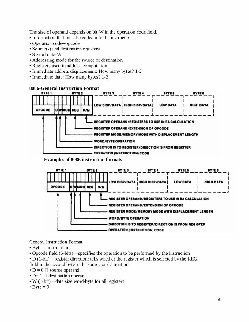
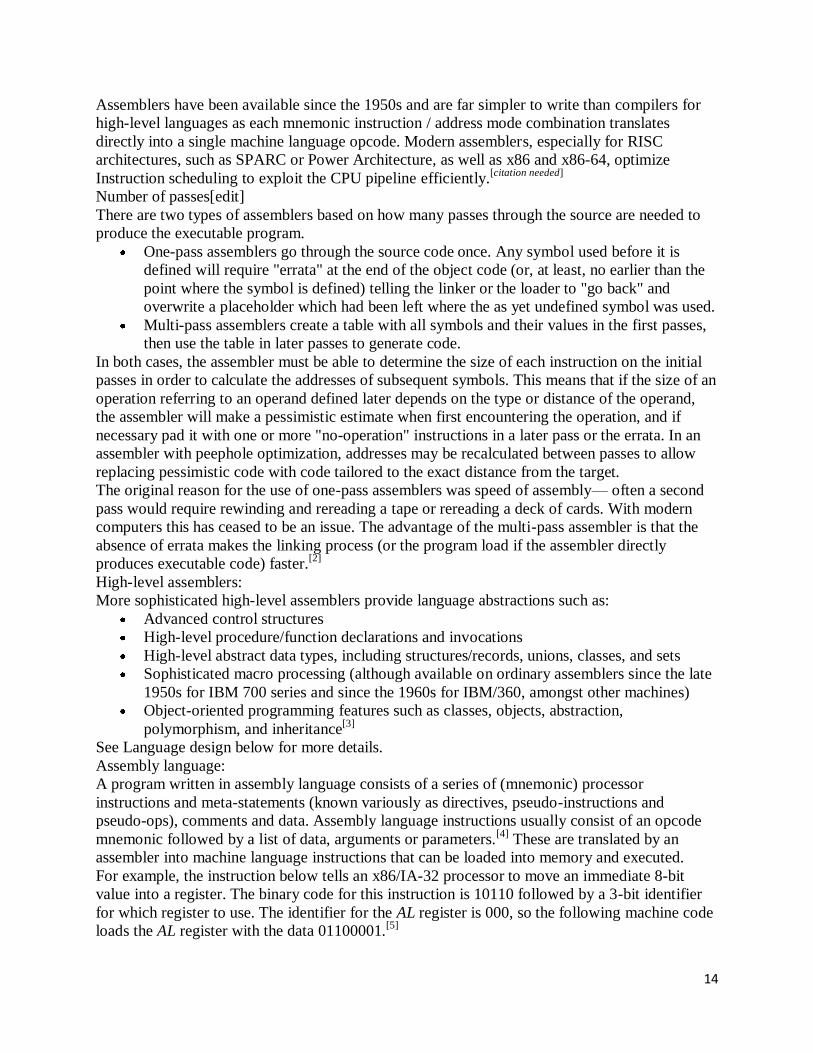
8086-General Instruction Format
Examples of 8086 instruction formats
General Instruction Format
• Byte 1 information:
• Opcode field (6-bits)—specifies the operation to be performed by the instruction
• D (1-bit)—register direction: tells whether the register which is selected by the REG
field in the second byte is the source or destination
• D = 0 � source operand
• D= 1 � destination operand
• W (1-bit)—data size word/byte for all registers
• Byte = 0

10
• Word =1
Byte 2 information:
MOD bits explanation
• MOD (2-bit mode field)—specifies the type of the second operand
• Memory mode: 00, 01,10—Register to memory move operation
• 00 = no immediate displacement (register used for addressing)
• 01 = 8-bit displacement (imm8) follows (8-bit offset address)
• 10 = 16-bit displacement (imm16) follows (16-bit offset address)
• Register mode: 11—register to register move operation
• 11 = register specified as the second operand
• REG (3-bit register field)—selects the register for a first operand, which may be
the source or destination
Register addresses
• Byte 2 information (continued):
• R/M (3-bit register/memory field)—specifies the second operand as a register or a
storage location in memory

11
• Dependent on MOD field
• Mod = 11 R/M selects a register
• R/M = 000 Accumulator register
• R/M= 001 = Count register
• R/M = 010 = Data Register
• Move register/memory to/from register
• Byte 1= 100010(d)(w)
• Byte 2 = (mod) (reg) (r/m)
• Affected by byte 1 information:
• W (1-bit)—data size word/byte for all registers
• Byte = 0
• Word =1
• D (1-bit)—register direction for first operand in byte 2 (reg)
• D = 0 � source operand
• D= 1 � destination operand
Register operand selection
Byte 2 information (continued):
• MOD = 00,10, or 10 selects an addressing mode for the second operand that is a
storage location in memory, which may be the source or destination
dependent on MOD field
• Mod = 00:
• R/M =100 � effective address computed as EA = (SI)
• R/M= 000 = � effective address computed as EA = (BX)+(SI)
• R/M =110 = � effective address is coded in the instruction as a direct
address
Effective Address (EA); direct address = imm8 or imm16

12
The S, V, Z fields of the opcode in specific instructions
• SR (2-bit segment register identifier field)—used in instructions to specify a segment
register
The segment register identifiers
writing programs for use with an assembler:

13
Assembly language is essentially the native language of your computer. Technically the
processor of your machine understands machine code (consisting of ones and zeroes). But in
order to write such a machine code program, you first write it in assembly language and then use
an assembler to convert it to machine code.
However nothing is lost when the assembler does its conversion, since assembly language simply
consists of mnemonic codes which are easy to remember (they are similar to words in the english
language), which stand for each of the different machine code instructions that the machine is
capable of executing.
Here is an example of a short excerpt from an assembly language program:
Mov EAX,1
Shl EAX,5
Mov ECX,17
Sub ECX,EAX
….
An assembler would convert this set of instructions into a series of ones and zeros (i.e. an
executable program) that the machine could understand.
assembly language program development tools:
An assembly language is a low-level programming language for a computer, or other
programmable device, in which there is a very strong (generally one-to-one) correspondence
between the language and the architecture's machine code instructions. Each assembly language
is specific to a particular computer architecture, in contrast to most high-level programming
languages, which are generally portable across multiple architectures, but require interpreters or
compiling.
Assembly language is converted into executable machine code by a utility program referred to as
an assembler; the conversion process is referred to as assembly, or assembling the code.
Assembly language uses a mnemonic to represent each low-level machine operation or opcode.
Some opcodes require one or more operands as part of the instruction, and most assemblers can
take labels and symbols as operands to represent addresses and constants, instead of hard coding
them into the program. Macro assemblers include a macroinstruction facility so that assembly
language text can be pre-assigned to a name, and that name can be used to insert the text into
other code. Many assemblers offer additional mechanisms to facilitate program development, to
control the assembly process, and to aid debugging.
Assembler:
An assembler creates object code by translating assembly instruction mnemonics into opcodes,
and by resolving symbolic names for memory locations and other entities.[1]
The use of symbolic
references is a key feature of assemblers, saving tedious calculations and manual address updates
after program modifications. Most assemblers also include macro facilities for performing
textual substitution—e.g., to generate common short sequences of instructions as inline, instead
of called subroutines.
14
Assemblers have been available since the 1950s and are far simpler to write than compilers for
high-level languages as each mnemonic instruction / address mode combination translates
directly into a single machine language opcode. Modern assemblers, especially for RISC
architectures, such as SPARC or Power Architecture, as well as x86 and x86-64, optimize
Instruction scheduling to exploit the CPU pipeline efficiently.[citation needed]
Number of passes[edit]
There are two types of assemblers based on how many passes through the source are needed to
produce the executable program.
One-pass assemblers go through the source code once. Any symbol used before it is
defined will require "errata" at the end of the object code (or, at least, no earlier than the
point where the symbol is defined) telling the linker or the loader to "go back" and
overwrite a placeholder which had been left where the as yet undefined symbol was used.
Multi-pass assemblers create a table with all symbols and their values in the first passes,
then use the table in later passes to generate code.
In both cases, the assembler must be able to determine the size of each instruction on the initial
passes in order to calculate the addresses of subsequent symbols. This means that if the size of an
operation referring to an operand defined later depends on the type or distance of the operand,
the assembler will make a pessimistic estimate when first encountering the operation, and if
necessary pad it with one or more "no-operation" instructions in a later pass or the errata. In an
assembler with peephole optimization, addresses may be recalculated between passes to allow
replacing pessimistic code with code tailored to the exact distance from the target.
The original reason for the use of one-pass assemblers was speed of assembly— often a second
pass would require rewinding and rereading a tape or rereading a deck of cards. With modern
computers this has ceased to be an issue. The advantage of the multi-pass assembler is that the
absence of errata makes the linking process (or the program load if the assembler directly
produces executable code) faster.[2]
High-level assemblers:
More sophisticated high-level assemblers provide language abstractions such as:
Advanced control structures
High-level procedure/function declarations and invocations
High-level abstract data types, including structures/records, unions, classes, and sets
Sophisticated macro processing (although available on ordinary assemblers since the late
1950s for IBM 700 series and since the 1960s for IBM/360, amongst other machines)
Object-oriented programming features such as classes, objects, abstraction,
polymorphism, and inheritance[3]
See Language design below for more details.
Assembly language:
A program written in assembly language consists of a series of (mnemonic) processor
instructions and meta-statements (known variously as directives, pseudo-instructions and
pseudo-ops), comments and data. Assembly language instructions usually consist of an opcode
mnemonic followed by a list of data, arguments or parameters.[4]
These are translated by an
assembler into machine language instructions that can be loaded into memory and executed.
For example, the instruction below tells an x86/IA-32 processor to move an immediate 8-bit
value into a register. The binary code for this instruction is 10110 followed by a 3-bit identifier
for which register to use. The identifier for the AL register is 000, so the following machine code
loads the AL register with the data 01100001.[5]
15
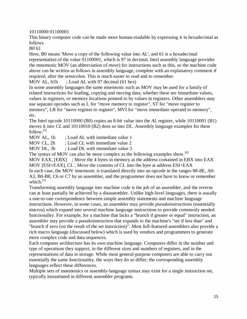
10110000 01100001
This binary computer code can be made more human-readable by expressing it in hexadecimal as
follows
B0 61
Here, B0 means 'Move a copy of the following value into AL', and 61 is a hexadecimal
representation of the value 01100001, which is 97 in decimal. Intel assembly language provides
the mnemonic MOV (an abbreviation of move) for instructions such as this, so the machine code
above can be written as follows in assembly language, complete with an explanatory comment if
required, after the semicolon. This is much easier to read and to remember.
MOV AL, 61h ; Load AL with 97 decimal (61 hex)
In some assembly languages the same mnemonic such as MOV may be used for a family of
related instructions for loading, copying and moving data, whether these are immediate values,
values in registers, or memory locations pointed to by values in registers. Other assemblers may
use separate opcodes such as L for "move memory to register", ST for "move register to
memory", LR for "move register to register", MVI for "move immediate operand to memory",
etc.
The Intel opcode 10110000 (B0) copies an 8-bit value into the AL register, while 10110001 (B1)
moves it into CL and 10110010 (B2) does so into DL. Assembly language examples for these
follow.[5]
MOV AL, 1h ; Load AL with immediate value 1
MOV CL, 2h ; Load CL with immediate value 2
MOV DL, 3h ; Load DL with immediate value 3
The syntax of MOV can also be more complex as the following examples show.[6]
MOV EAX, [EBX] ; Move the 4 bytes in memory at the address contained in EBX into EAX
MOV [ESI+EAX], CL ; Move the contents of CL into the byte at address ESI+EAX
In each case, the MOV mnemonic is translated directly into an opcode in the ranges 88-8E, A0-
A3, B0-B8, C6 or C7 by an assembler, and the programmer does not have to know or remember
which.[5]
Transforming assembly language into machine code is the job of an assembler, and the reverse
can at least partially be achieved by a disassembler. Unlike high-level languages, there is usually
a one-to-one correspondence between simple assembly statements and machine language
instructions. However, in some cases, an assembler may provide pseudoinstructions (essentially
macros) which expand into several machine language instructions to provide commonly needed
functionality. For example, for a machine that lacks a "branch if greater or equal" instruction, an
assembler may provide a pseudoinstruction that expands to the machine's "set if less than" and
"branch if zero (on the result of the set instruction)". Most full-featured assemblers also provide a
rich macro language (discussed below) which is used by vendors and programmers to generate
more complex code and data sequences.
Each computer architecture has its own machine language. Computers differ in the number and
type of operations they support, in the different sizes and numbers of registers, and in the
representations of data in storage. While most general-purpose computers are able to carry out
essentially the same functionality, the ways they do so differ; the corresponding assembly
languages reflect these differences.
Multiple sets of mnemonics or assembly-language syntax may exist for a single instruction set,
typically instantiated in different assembler programs.

16
UNIT-II Implementing standard program structures in 8086 assembly language:Simple sequence
programs, jumps, flags and conditional jumps, if-then, if-then-else ,multiple if-then-else
programs,while-do programs, repeat-until programs,instruction timing and delay loops.
2.1 Implementing standard program structures in 8086 assembly language:
Program flow control
Controlling the program flow is a very important thing, this is where your program can make
decisions according to certain conditions.
unconditional jumps
The basic instruction that transfers control to another point in the program is JMP.
The basic syntax of JMP instruction:
JMP label
To declare a label in your program, just type its name and add ":" to the end, label can be
any character combination but it cannot start with a number, for example here are 3 legal
label definitions:
label1:
label2:
a:
Label can be declared on a separate line or before any other instruction, for example:
x1:
MOV AX, 1
x2: MOV AX, 2
here's an example of JMP instruction:
org 100h
mov ax, 5 ; set ax to 5.
mov bx, 2 ; set bx to 2.
jmp calc ; go to 'calc'.
back: jmp stop ; go to 'stop'.
calc:
add ax, bx ; add bx to ax.
jmp back ; go 'back'.
stop:
ret ; return to operating system.

17
Of course there is an easier way to calculate the some of two numbers, but it's still a good
example of JMP instruction.
As you can see from this example JMP is able to transfer control both forward and
backward. It can jump anywhere in current code segment (65,535 bytes).
Short Conditional Jumps
Unlike JMP instruction that does an unconditional jump, there are instructions that do a
conditional jumps (jump only when some conditions are in act). These instructions are
divided in three groups, first group just test single flag, second compares numbers as
signed, and third compares numbers as unsigned.
Jump instructions that test single flag
Instruction Description Condition Opposite
Instruction
JZ , JE Jump if Zero (Equal). ZF = 1 JNZ, JNE
JC , JB, JNAE Jump if Carry (Below, Not Above
Equal). CF = 1 JNC, JNB, JAE
JS Jump if Sign. SF = 1 JNS
JO Jump if Overflow. OF = 1 JNO
JPE, JP Jump if Parity Even. PF = 1 JPO
JNZ , JNE Jump if Not Zero (Not Equal). ZF = 0 JZ, JE
JNC , JNB,
JAE
Jump if Not Carry (Not Below,
Above Equal). CF = 0 JC, JB, JNAE
JNS Jump if Not Sign. SF = 0 JS
JNO Jump if Not Overflow. OF = 0 JO
JPO, JNP Jump if Parity Odd (No Parity). PF = 0 JPE, JP
as you may already notice there are some instructions that do that same thing, that's
correct, they even are assembled into the same machine code, so it's good to remember
that when you compile JE instruction - you will get it disassembled as: JZ, JC is
assembled the same as JB etc...
different names are used to make programs easier to understand, to code and most
importantly to remember. very offset dissembler has no clue what the original instruction
was look like that's why it uses the most common name.
18
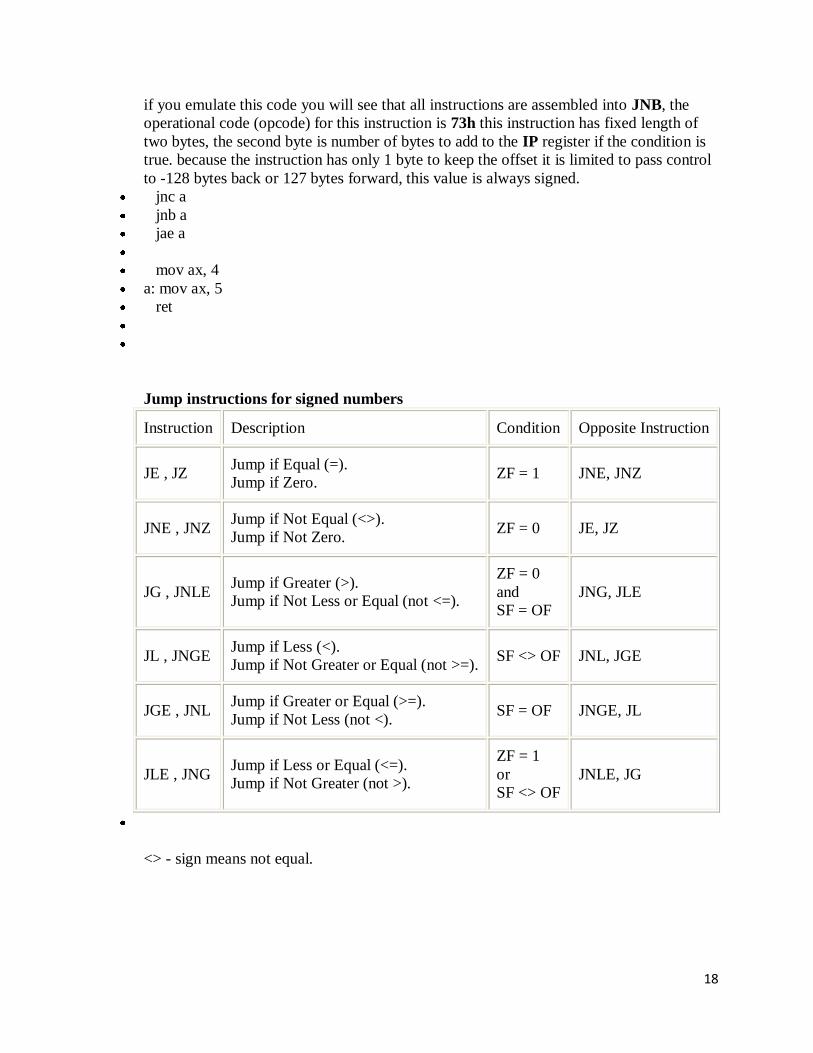
if you emulate this code you will see that all instructions are assembled into JNB, the
operational code (opcode) for this instruction is 73h this instruction has fixed length of
two bytes, the second byte is number of bytes to add to the IP register if the condition is
true. because the instruction has only 1 byte to keep the offset it is limited to pass control
to -128 bytes back or 127 bytes forward, this value is always signed.
jnc a
jnb a
jae a
mov ax, 4
a: mov ax, 5
ret
Jump instructions for signed numbers
Instruction Description Condition Opposite Instruction
JE , JZ Jump if Equal (=).
Jump if Zero. ZF = 1 JNE, JNZ
JNE , JNZ Jump if Not Equal (<>).
Jump if Not Zero. ZF = 0 JE, JZ
JG , JNLE Jump if Greater (>).
Jump if Not Less or Equal (not <=).
ZF = 0
and
SF = OF
JNG, JLE
JL , JNGE Jump if Less (<).
Jump if Not Greater or Equal (not >=). SF <> OF JNL, JGE
JGE , JNL Jump if Greater or Equal (>=).
Jump if Not Less (not <). SF = OF JNGE, JL
JLE , JNG Jump if Less or Equal (<=).
Jump if Not Greater (not >).
ZF = 1
or
SF <> OF
JNLE, JG
<> - sign means not equal.

19
Jump instructions for unsigned numbers
Instruction Description Condition Opposite
Instruction
JE , JZ Jump if Equal (=).
Jump if Zero. ZF = 1 JNE, JNZ
JNE , JNZ Jump if Not Equal (<>).
Jump if Not Zero. ZF = 0 JE, JZ
JA , JNBE
Jump if Above (>).
Jump if Not Below or Equal (not
<=).
CF = 0
and
ZF = 0
JNA, JBE
JB , JNAE, JC
Jump if Below (<).
Jump if Not Above or Equal (not
>=).
Jump if Carry.
CF = 1 JNB, JAE, JNC
JAE , JNB,
JNC
Jump if Above or Equal (>=).
Jump if Not Below (not <).
Jump if Not Carry.
CF = 0 JNAE, JB
JBE , JNA Jump if Below or Equal (<=).
Jump if Not Above (not >).
CF = 1
or
ZF = 1
JNBE, JA
Generally, when it is required to compare numeric values CMP instruction is used (it
does the same as SUB (subtract) instruction, but does not keep the result, just affects the
flags).
The logic is very simple, for example:
it's required to compare 5 and 2,
5 - 2 = 3
the result is not zero (Zero Flag is set to 0).
Another example:
it's required to compare 7 and 7,
7 - 7 = 0
the result is zero! (Zero Flag is set to 1 and JZ or JE will do the jump).
here's an example of CMP instruction and conditional jump:

20
include "emu8086.inc"
org 100h
mov al, 25 ; set al to 25.
mov bl, 10 ; set bl to 10.
cmp al, bl ; compare al - bl.
je equal ; jump if al = bl (zf = 1).
putc 'n' ; if it gets here, then al <> bl,
jmp stop ; so print 'n', and jump to stop.
equal: ; if gets here,
putc 'y' ; then al = bl, so print 'y'.
stop:
ret ; gets here no matter what.
try the above example with different numbers for AL and BL, open flags by clicking on
flags button, use single step and see what happens. you can use F5 hotkey to recompile
and reload the program into the emulator.
loops
instruction operation and jump condition opposite
instruction
LOOP decrease cx, jump to label if cx not zero. DEC CX and
JCXZ
LOOPE decrease cx, jump to label if cx not zero and equal (zf
= 1). LOOPNE
LOOPNE decrease cx, jump to label if cx not zero and not
equal (zf = 0). LOOPE
LOOPNZ decrease cx, jump to label if cx not zero and zf = 0. LOOPZ
LOOPZ decrease cx, jump to label if cx not zero and zf = 1. LOOPNZ
JCXZ jump to label if cx is zero. OR CX, CX and

21
JNZ
loops are basically the same jumps, it is possible to code loops without using the loop
instruction, by just using conditional jumps and compare, and this is just what loop does.
all loop instructions use CX register to count steps, as you know CX register has 16 bits
and the maximum value it can hold is 65535 or FFFF, however with some agility it is
possible to put one loop into another, and another into another two, and three and etc...
and receive a nice value of 65535 * 65535 * 65535 ....till infinity.... or the end of ram or
stack memory. it is possible store original value of cx register using push cx instruction
and return it to original when the internal loop ends with pop cx, for example:
org 100h
mov bx, 0 ; total step counter.
mov cx, 5
k1: add bx, 1
mov al, '1'
mov ah, 0eh
int 10h
push cx
mov cx, 5
k2: add bx, 1
mov al, '2'
mov ah, 0eh
int 10h
push cx
mov cx, 5
k3: add bx, 1
mov al, '3'
mov ah, 0eh
int 10h
loop k3 ; internal in internal loop.
pop cx
loop k2 ; internal loop.
pop cx
loop k1 ; external loop.
ret
bx counts total number of steps, by default emulator shows values in hexadecimal, you
can double click the register to see the value in all available bases.
just like all other conditional jumps loops have an opposite companion that can help to
create workarounds, when the address of desired location is too far assemble

22
automatically assembles reverse and long jump instruction, making total of 5 bytes
instead of just 2, it can be seen in disassembler as well.
All conditional jumps have one big limitation, unlike JMP instruction they can only jump
127 bytes forward and 128 bytes backward (note that most instructions are assembled
into 3 or more bytes).
We can easily avoid this limitation using a cute trick:
o Get an opposite conditional jump instruction from the table above, make it jump
to label_x.
o Use JMP instruction to jump to desired location.
o Define label_x: just after the JMP instruction.
label_x: - can be any valid label name, but there must not be two or more labels with the
same name.
here's an example:
include "emu8086.inc"
org 100h
mov al, 5
mov bl, 5
cmp al, bl ; compare al - bl.
jne not_equal ; jump if al <> bl (zf = 0).
jmp equal
not_equal:
add bl, al
sub al, 10
xor al, bl
jmp skip_data
db 256 dup(0) ; 256 bytes
skip_data:
putc 'n' ; if it gets here, then al <> bl,
jmp stop ; so print 'n', and jump to stop.
equal: ; if gets here,
putc 'y' ; then al = bl, so print 'y'.
stop:

23
ret
Note: the latest version of the integrated 8086 assembler automatically creates a workaround by
replacing the conditional jump with the opposite, and adding big unconditional jump. To check if
you have the latest version of emu8086 click help-> check for an update from the menu.
Another, yet rarely used method is providing an immediate value instead of label. When
immediate value starts with $ relative jump is performed, otherwise compiler calculates
instruction that jumps directly to given offset. For example:
org 100h
; unconditional jump forward:
; skip over next 3 bytes + itself
; the machine code of short jmp instruction
takes 2 bytes.
jmp $3+2
a db 3 ; 1 byte.
b db 4 ; 1 byte.
c db 4 ; 1 byte.
; conditional jump back 5 bytes:
mov bl,9
dec bl ; 2 bytes.
cmp bl, 0 ; 3 bytes.
jne $-5 ; jump 5 bytes back
ret
Variations on Loops
A loop is a programming building block which allows you to repeat certain instructions until
some predefined condition holds (or until a condition is no longer met, which is logically
equivalent). Many loops simply repeat for a predefined number of iterations, but others are more
complicated. Every processor architecture has instructions specifically designed to facilitate loop
control. We treat here various methods for writing loops on the x86 processor family.
The writing of loop code is most easily shown by example; here we use a simple task of clearing
a block of memory. The C version of this would be the following for loop:
for(i=0; i<100; i++)
list[i] = 0;
Assume in the following that the memory block has been defined elsewhere with first byte
address, ListBegin, and (last byte + 1) address, ListEnd (note this means that the last location to
be cleared is the one before ListEnd), e.g.:
ListBegin resb 100 ; reserve 100 bytes
ListEnd equ $ ; define as last-byte-address+1
In these examples, BX is used as a pointer into the memory block.
24
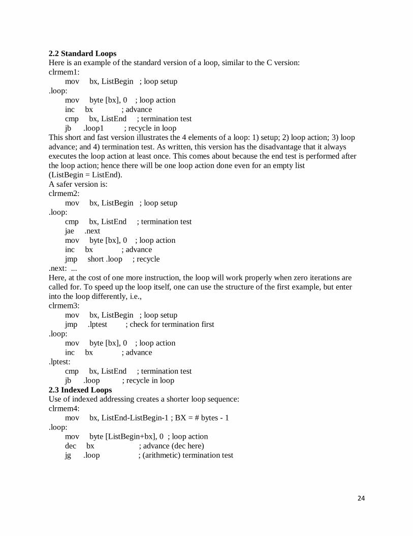
2.2 Standard Loops
Here is an example of the standard version of a loop, similar to the C version:
clrmem1:
mov bx, ListBegin ; loop setup
.loop:
mov byte [bx], 0 ; loop action
inc bx ; advance
cmp bx, ListEnd ; termination test
jb .loop1 ; recycle in loop
This short and fast version illustrates the 4 elements of a loop: 1) setup; 2) loop action; 3) loop
advance; and 4) termination test. As written, this version has the disadvantage that it always
executes the loop action at least once. This comes about because the end test is performed after
the loop action; hence there will be one loop action done even for an empty list
(ListBegin = ListEnd).
A safer version is:
clrmem2:
mov bx, ListBegin ; loop setup
.loop:
cmp bx, ListEnd ; termination test
jae .next
mov byte [bx], 0 ; loop action
inc bx ; advance
jmp short .loop ; recycle
.next: ...
Here, at the cost of one more instruction, the loop will work properly when zero iterations are
called for. To speed up the loop itself, one can use the structure of the first example, but enter
into the loop differently, i.e.,
clrmem3:
mov bx, ListBegin ; loop setup
jmp .lptest ; check for termination first
.loop:
mov byte [bx], 0 ; loop action
inc bx ; advance
.lptest:
cmp bx, ListEnd ; termination test
jb .loop ; recycle in loop
2.3 Indexed Loops
Use of indexed addressing creates a shorter loop sequence:
clrmem4:
mov bx, ListEnd-ListBegin-1 ; BX = # bytes - 1
.loop:
mov byte [ListBegin+bx], 0 ; loop action
dec bx ; advance (dec here)
jg .loop ; (arithmetic) termination test
25
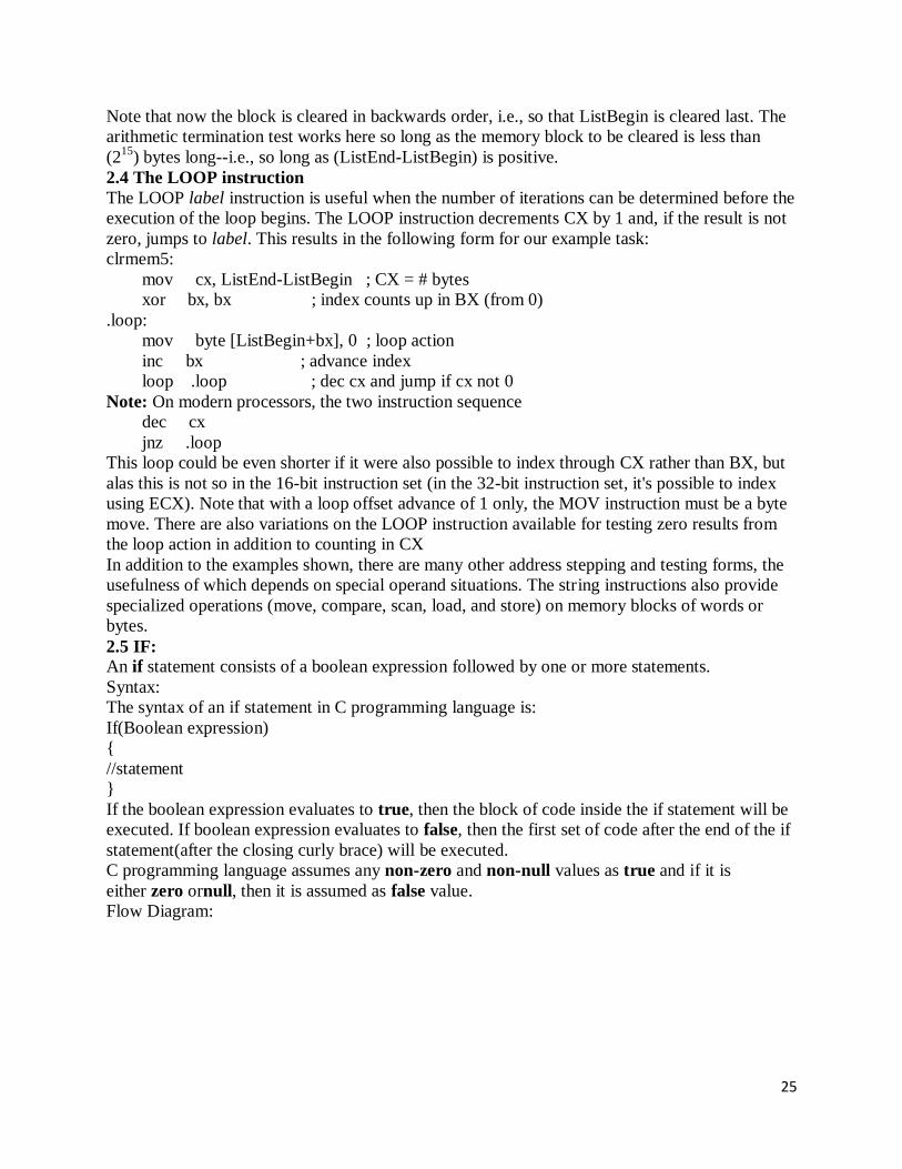
Note that now the block is cleared in backwards order, i.e., so that ListBegin is cleared last. The
arithmetic termination test works here so long as the memory block to be cleared is less than
(215
) bytes long--i.e., so long as (ListEnd-ListBegin) is positive.
2.4 The LOOP instruction
The LOOP label instruction is useful when the number of iterations can be determined before the
execution of the loop begins. The LOOP instruction decrements CX by 1 and, if the result is not
zero, jumps to label. This results in the following form for our example task:
clrmem5:
mov cx, ListEnd-ListBegin ; CX = # bytes
xor bx, bx ; index counts up in BX (from 0)
.loop:
mov byte [ListBegin+bx], 0 ; loop action
inc bx ; advance index
loop .loop ; dec cx and jump if cx not 0
Note: On modern processors, the two instruction sequence
dec cx
jnz .loop
This loop could be even shorter if it were also possible to index through CX rather than BX, but
alas this is not so in the 16-bit instruction set (in the 32-bit instruction set, it's possible to index
using ECX). Note that with a loop offset advance of 1 only, the MOV instruction must be a byte
move. There are also variations on the LOOP instruction available for testing zero results from
the loop action in addition to counting in CX
In addition to the examples shown, there are many other address stepping and testing forms, the
usefulness of which depends on special operand situations. The string instructions also provide
specialized operations (move, compare, scan, load, and store) on memory blocks of words or
bytes.
2.5 IF:
An if statement consists of a boolean expression followed by one or more statements.
Syntax:
The syntax of an if statement in C programming language is:
If(Boolean expression)
{
//statement
}
If the boolean expression evaluates to true, then the block of code inside the if statement will be
executed. If boolean expression evaluates to false, then the first set of code after the end of the if
statement(after the closing curly brace) will be executed.
C programming language assumes any non-zero and non-null values as true and if it is
either zero ornull, then it is assumed as false value.
Flow Diagram:

26
In its most basic form, a decision is some sort of branch within the code that switches between
two possible execution paths based on some condition. Normally (though not always),
conditional instruction sequences are implemented with the conditional jump instructions.
Conditional instructions correspond to the if..then..else statement in Pascal:
IF (condition is true) THEN stmt1 ELSE stmt2 ;
Assembly language, as usual, offers much more flexibility when dealing with conditional
statements. Consider the following Pascal statement:
IF ((X<Y) and (Z > T)) or (A <> B) THEN stmt1;
A "brute force" approach to converting this statement into assembly language might produce:
mov cl, 1 ;Assume true
mov ax, X
cmp ax, Y
jl IsTrue
mov cl, 0 ;This one's false
IsTrue: mov ax, Z
cmp ax, T
jg AndTrue
mov cl, 0 ;It's false now
AndTrue: mov al, A
cmp al, B
je OrFalse
mov cl, 1 ;Its true if A <> B
OrFalse: cmp cl, 1
jne SkipStmt1
<Code for stmt1 goes here>
SkipStmt1:
As you can see, it takes a considerable number of conditional statements just to process the
expression in the example above. This roughly corresponds to the (equivalent) Pascal statements:
cl := true;
IF (X >= Y) then cl := false;
IF (Z <= T) then cl := false;

27
IF (A <> B) THEN cl := true;
IF (CL = true) then stmt1;
Now compare this with the following "improved" code:
mov ax, A
cmp ax, B
jne DoStmt
mov ax, X
cmp ax, Y
jnl SkipStmt
mov ax, Z
cmp ax, T
jng SkipStmt
DoStmt:
<Place code for Stmt1 here>
SkipStmt:
Two things should be apparent from the code sequences above: first, a single conditional
statement in Pascal may require several conditional jumps in assembly language; second,
organization of complex expressions in a conditional sequence can affect the efficiency of the
code. Therefore, care should be exercised when dealing with conditional sequences in assembly
language.
Conditional statements may be broken down into three basic categories: if..then..else statements,
case statements, and indirect jumps. The following sections will describe these program
structures, how to use them, and how to write them in assembly language.
2.6 IF..THEN..ELSE Sequences
The most commonly used conditional statement is theif..then or if..then..else statement. These
two statements take the following form shown below:
The if..then statement is just a special case of the if..then..else statement (with an empty
ELSE block). Therefore, we'll only consider the more general if..then..else form. The basic
implementation of an if..then..else statement in 80x86 assembly language looks something
like this:
{Sequence of statements to test some condition}
Jcc ElseCode
{Sequence of statements corresponding to the THEN block}
jmp EndOfIF
ElseCode:
{Sequence of statements corresponding to the ELSE block}
EndOfIF:

28
Note: Jcc represents some conditional jump instruction.
For example, to convert the Pascal statement:
IF (a=b) then c := d else b := b + 1;
to assembly language, you could use the following 80x86 code:
mov ax, a
cmp ax, b
jne ElseBlk
mov ax, d
mov c, ax
jmp EndOfIf
ElseBlk:
inc b
EndOfIf:
For simple expressions like (A=B) generating the proper code for an if..then..else statement is
almost trivial. Should the expression become more complex, the associated assembly language
code complexity increases as well. Consider the following if statement presented earlier:
IF ((X > Y) and (Z < T)) or (A<>B) THEN C := D;
When processing complex if statements such as this one, you'll find the conversion task easier if
you break this if statement into a sequence of three different if statements as follows:
IF (A<>B) THEN C := D
IF (X > Y) THEN IF (Z < T) THEN C := D;
This conversion comes from the following Pascal equivalences:
IF (expr1 AND expr2) THEN stmt;
is equivalent to
IF (expr1) THEN IF (expr2) THEN stmt;
and
IF (expr1 OR expr2) THEN stmt;
is equivalent to
IF (expr1) THEN stmt;
IF (expr2) THEN stmt;
In assembly language, the former if statement becomes:
mov ax, A
cmp ax, B
jne DoIF
mov ax, X
cmp ax, Y
jng EndOfIf
mov ax, Z
cmp ax, T
jnl EndOfIf

29
DoIf:
mov ax, D
mov C, ax
EndOfIF:
As you can probably tell, the code necessary to test a condition can easily become more complex
than the statements appearing in the else and then blocks. Although it seems somewhat
paradoxical that it may take more effort to test a condition than to act upon the results of that
condition, it happens all the time. Therefore, you should be prepared for this situation.
Probably the biggest problem with the implementation of complex conditional statements in
assembly language is trying to figure out what you've done after you've written the code.
Probably the biggest advantage high level languages offer over assembly language is that
expressions are much easier to read and comprehend in a high level language. The HLL version
is self-documenting whereas assembly language tends to hide the true nature of the code.
Therefore, well-written comments are an essential ingredient to assembly language
implementations of if..then..else statements. An elegant implementation of the example above is:
; IF ((X > Y) AND (Z < T)) OR (A <> B) THEN C := D;
; Implemented as:
; IF (A <> B) THEN GOTO DoIF;
mov ax, A
cmp ax, B
jne DoIF
; IF NOT (X > Y) THEN GOTO EndOfIF;
mov ax, X
cmp ax, Y
jng EndOfIf
; IF NOT (Z < T) THEN GOTO EndOfIF ;
mov ax, Z
cmp ax, T
jnl EndOfIf
; THEN Block:
DoIf: mov ax, D
mov C, ax
; End of IF statement
EndOfIF:
30
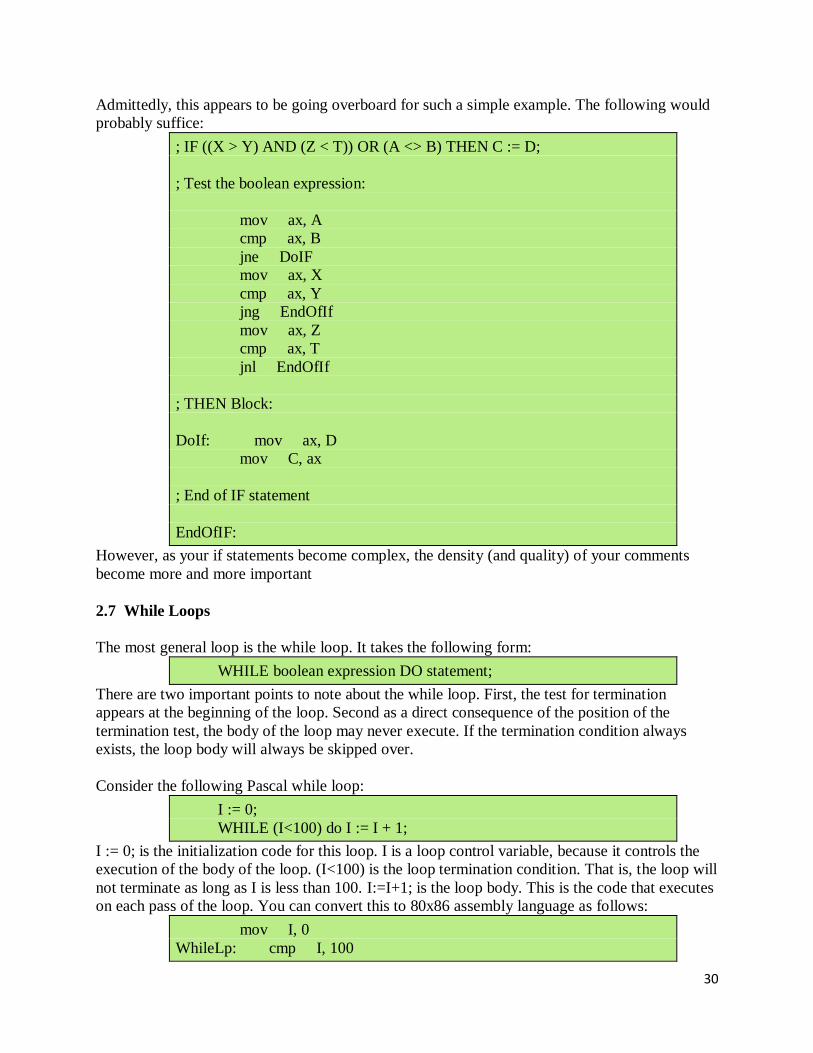
Admittedly, this appears to be going overboard for such a simple example. The following would
probably suffice:
; IF ((X > Y) AND (Z < T)) OR (A <> B) THEN C := D;
; Test the boolean expression:
mov ax, A
cmp ax, B
jne DoIF
mov ax, X
cmp ax, Y
jng EndOfIf
mov ax, Z
cmp ax, T
jnl EndOfIf
; THEN Block:
DoIf: mov ax, D
mov C, ax
; End of IF statement
EndOfIF:
However, as your if statements become complex, the density (and quality) of your comments
become more and more important
2.7 While Loops
The most general loop is the while loop. It takes the following form:
WHILE boolean expression DO statement;
There are two important points to note about the while loop. First, the test for termination
appears at the beginning of the loop. Second as a direct consequence of the position of the
termination test, the body of the loop may never execute. If the termination condition always
exists, the loop body will always be skipped over.
Consider the following Pascal while loop:
I := 0;
WHILE (I<100) do I := I + 1;
I := 0; is the initialization code for this loop. I is a loop control variable, because it controls the
execution of the body of the loop. (I<100) is the loop termination condition. That is, the loop will
not terminate as long as I is less than 100. I:=I+1; is the loop body. This is the code that executes
on each pass of the loop. You can convert this to 80x86 assembly language as follows:
mov I, 0
WhileLp: cmp I, 100

31
jge WhileDone
inc I
jmp WhileLp
WhileDone:
Note that a Pascal while loop can be easily synthesized using an if and a goto statement. For
example, the Pascal while loop presented above can be replaced by:
I := 0;
1: IF (I<100) THEN BEGIN
I := I + 1;
GOTO 1;
END;
More generally, any while loop can be built up from the following:
optional initialization code
1: IF not termination condition THEN BEGIN
loop body
GOTO 1;
END;
Therefore, you can use the techniques from earlier in this chapter to convert if statements to
assembly language. All you'll need is an additional jmp (goto) instruction.
2.8 Repeat..Until Loops
The repeat..until (do..while) loop tests for the termination condition at the end of the loop rather
than at the beginning. In Pascal, the repeat..until loop takes the following form:
optional initialization code
REPEAT
loop body
UNTIL termination condition
This sequence executes the initialization code, the loop body, then tests some condition to see if
the loop should be repeated. If the boolean expression evaluates to false, the loop repeats;
otherwise the loop terminates. The two things to note about the repeat..until loop is that the
termination test appears at the end of the loop and, as a direct consequence of this, the loop body
executes at least once.
Like the while loop, the repeat..until loop can be synthesized with an if statement and a goto .
You would use the following:
initialization code
1: loop body
IF NOT termination condition THEN GOTO 1
Based on the material presented in the previous sections, you can easily synthesize repeat..until
loops in assembly language.
2.9 LOOP..ENDLOOP Loops

32
If while loops test for termination at the beginning of the loop and repeat..until loops check for
termination at the end of the loop, the only place left to test for termination is in the middle of the
loop. Although Pascal and C/C++[4] don't directly support such a loop, the loop..endloop
structure can be found in HLL languages like Ada. The loop..endloop loop takes the following
form:
LOOP
loop body
ENDLOOP;
Note that there is no explicit termination condition. Unless otherwise provided for, the
loop..endloop construct simply forms an infinite loop. Loop termination is handled by an if and
goto statement[5]. Consider the following (pseudo) Pascal code which employs a loop..endloop
construct:
LOOP
READ(ch)
IF ch = '.' THEN BREAK;
WRITE(ch);
ENDLOOP;
In real Pascal, you'd use the following code to accomplish this:
1:
READ(ch);
IF ch = '.' THEN GOTO 2; (* Turbo Pascal supports BREAK! *)
WRITE(ch);
GOTO 1
2:
In assembly language you'd end up with something like:
LOOP1: getc
cmp al, '.'
je EndLoop
putc
jmp LOOP1
EndLoop:
FOR Loops
The for loop is a special form of the while loop which repeats the loop body a specific number of
times. In Pascal, the for loop looks something like the following:
FOR var := initial TO final DO stmt
or
FOR var := initial DOWNTO final DO stmt
Traditionally, the for loop in Pascal has been used to process arrays and other objects accessed in
sequential numeric order. These loops can be converted directly into assembly language as
follows:
In Pascal:

33
FOR var := start TO stop DO stmt;
In Assembly:
mov var, start
FL: mov ax, var
cmp ax, stop
jg EndFor
; code corresponding to stmt goes here.
inc var
jmp FL
EndFor:
Fortunately, most for loops repeat some statement(s) a fixed number of times. For example,
FOR I := 0 to 7 do write(ch);
In situations like this, it's better to use the 80x86 loop instruction (or corresponding dec cx/jne
sequence) rather than simulate a for loop:
mov cx, 7
LP: mov al, ch
call putc
loop LP
Keep in mind that the loop instruction normally appears at the end of a loop whereas the for loop
tests for termination at the beginning of the loop. Therefore, you should take precautions to
prevent a runaway loop in the event cx is zero (which would cause the loop instruction to repeat
the loop 65,536 times) or the stop value is less than the start value. In the case of
FOR var := start TO stop DO stmt;
assuming you don't use the value of var within the loop, you'd probably want to use the assembly
code:
mov cx, stop
sub cx, start
jl SkipFor
inc cx
LP: stmt
loop LP
SkipFor:
Remember, the sub and cmp instructions set the flags in an identical fashion. Therefore, this loop
will be skipped if stop is less than start. It will be repeated (stop-start)+1 times otherwise. If you
need to reference the value of var within the loop, you could use the following code:
mov ax, start
mov var, ax
mov cx, stop
sub cx, ax
jl SkipFor

34
inc cx
LP: stmt
inc var
loop LP
SkipFor:
The downto version appears in the exercises.
Register Usage and Loops
Given that the 80x86 accesses registers much faster than memory locations, registers are the
ideal spot to place loop control variables (especially for small loops). This point is amplified
since the loop instruction requires the use of the cx register. However, there are some problems
associated with using registers within a loop. The primary problem with using registers as loop
control variables is that registers are a limited resource. In particular, there is only one cx
register. Therefore, the following will not work properly:
mov cx, 8
Loop1: mov cx, 4
Loop2: stmts
loop Loop2
stmts
loop Loop1
The intent here, of course, was to create a set of nested loops, that is, one loop inside another.
The inner loop (Loop2) should repeat four times for each of the eight executions of the outer
loop (Loop1). Unfortunately, both loops use the loop instruction. Therefore, this will form an
infinite loop since cx will be set to zero (which loop treats like 65,536) at the end of the first loop
instruction. Since cx is always zero upon encountering the second loop instruction, control will
always transfer to the Loop1 label. The solution here is to save and restore the cx register or to
use a different register in place of cx for the outer loop:
mov cx, 8
Loop1: push cx
mov cx, 4
Loop2: stmts
loop Loop2
pop cx
stmts
loop Loop1
or:
mov bx, 8
Loop1: mov cx, 4
Loop2: stmts
loop Loop2
stmts
dec bx
jnz Loop1
35
Register corruption is one of the primary sources of bugs in loops in assembly language
programs, always keep an eye out for this problem.
Repeat..Until Loops
The repeat..until (do..while) loop tests for the termination condition at the end of the loop rather
than at the beginning. In Pascal, the repeat..until loop takes the following form:
optional initialization code
REPEAT
loop body
UNTIL termination condition
This sequence executes the initialization code, the loop body, then tests some condition to see if
the loop should be repeated. If the boolean expression evaluates to false, the loop repeats;
otherwise the loop terminates. The two things to note about the repeat..until loop is that the
termination test appears at the end of the loop and, as a direct consequence of this, the loop body
executes at least once.
Like the while loop, the repeat..until loop can be synthesized with an if statement and a goto .
You would use the following:
initialization code
1: loop body
IF NOT termination condition THEN GOTO 1
Based on the material presented in the previous sections, you can easily synthesize repeat..until
loops in assembly language.

36
UNIT-3 Strings , procedures and macros, The 8086 string instructions, writing and using procedures,
writing and using assembler macros.
3.1 Strings: String instructions
8086 has instructions that work on a character string also. The instruction mnemonics end
with S.
String Instructions
MOVS
CMPS
STOS
LODS
SCAS
3.1.1 MOVS (MOVe String) instruction
Used for copying a string byte or word at a time. MOVSB for Move String Byte at a time.
MOVSW for Move String Word at a time. MOVSB and MOVSW are more common than
MOVS. Flags are not affected by the execution of MOVS/MOVSB/MOVSW instruction.
Instruction Source pointed
by
Destination
pointed by
If D = 0 If D = 1
MOVSB DS:SI ES:DI incr. by 1 SI and
DI
decr. by 1 SI and
DI
MOVSW DS:SI ES:DI incr. by 2 SI and
DI
decr. by 2 SI and
DI
MOVSB is equivalent to (assuming D = 0) MOVSW is equivalent to (assuming D = 0)
MOV AL, [SI] MOV AX, [SI]
MOV ES:[DI], AL MOV ES:[DI], AX
PUSHF PUSHF
INC SI ADD SI, 2
INC DI ADD DI, 2
POPF; Flags not affected POPF; Flags not affected
It is usual to have REP (for REPeat) prefix for MOVSB / MOVSW instruction. The
following code moves a 6-character string, as CX has 06. Without REP prefix, six
MOVSB instructions are needed.
MOV CX, 06
REP MOVSB
EXIT: MOV DL, BL
37
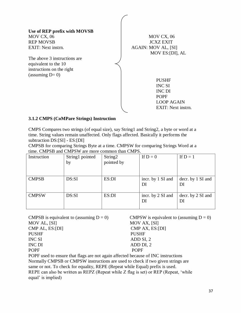
Use of REP prefix with MOVSB
MOV CX, 06 MOV CX, 06
REP MOVSB JCXZ EXIT
EXIT: Next instrn. AGAIN: MOV AL, [SI]
MOV ES:[DI], AL
The above 3 instructions are
equivalent to the 10
instructions on the right
(assuming D= 0)
PUSHF
INC SI
INC DI
POPF
LOOP AGAIN
EXIT: Next instrn.
3.1.2 CMPS (CoMPare Strings) Instruction
CMPS Compares two strings (of equal size), say String1 and String2, a byte or word at a
time. String values remain unaffected. Only flags affected. Basically it performs the
subtraction DS:[SI] - ES:[DI]
CMPSB for comparing Strings Byte at a time. CMPSW for comparing Strings Word at a
time. CMPSB and CMPSW are more common than CMPS.
Instruction String1 pointed
by
String2
pointed by
If D = 0 If D = 1
CMPSB DS:SI ES:DI incr. by 1 SI and
DI
decr. by 1 SI and
DI
CMPSW DS:SI ES:DI incr. by 2 SI and
DI
decr. by 2 SI and
DI
CMPSB is equivalent to (assuming D = 0) CMPSW is equivalent to (assuming D = 0)
MOV AL, [SI] MOV AX, [SI]
CMP AL, ES:[DI] CMP AX, ES:[DI]
PUSHF PUSHF
INC SI ADD SI, 2
INC DI ADD DI, 2
POPF POPF
POPF used to ensure that flags are not again affected because of INC instructions
Normally CMPSB or CMPSW instructions are used to check if two given strings are
same or not. To check for equality, REPE (Repeat while Equal) prefix is used.
REPE can also be written as REPZ (Repeat while Z flag is set) or REP (Repeat, ‘while
equal’ is implied)

38
Use of REPE prefix with CMPSB
MOV CX, 08 MOV CX, 08
REPE CMPSB JCXZ EXIT
EXIT: JE EQUAL AGAIN: MOV AL, [SI]
CMP AL, ES:[DI]
The above 3 instructions are equivalent to the
10 instructions on the right (assuming D= 0).
REPE CMPSB instruction causes CMPSB to
be repeated as long as the compared bytes are
equal and CX contents is not yet 0000.
PUSHF
INC SI
INC DI
POPF
LOOPE AGAIN
EXIT: JE EQUAL
REPNE (Repeat while not Equal) prefix is also present REPNE can also be written as
REPNZ (Repeat while Zero flag is not set).
REPNE CMPSB causes CMPSB instruction to be repeated as long as the compared bytes
are not equal and CX content is not yet 0000. REPNE prefix is not commonly used.
3.1.3 STOS (STOre String) instruction
STOS is used for creating a string in memory a byte or word at a time. AL/AX contents
copied to memory pointed by ES:[DI]. It does not affect any flag. STOSB is used for
storing string byte at a time. STOSW is used for storing string word at a time. STOSB
and STOSW are more common than STOS. Flags are not affected by the execution of
this instruction.
Instruction Source Destination
If D = 0 If D = 1
STOSB AL ES:DI incr. DI by 1 decr. DI by 1
STOSW AX ES:DI incr. DI by 2 decr. DI by 2
STOSB is equivalent to (assuming D = 0) STOSW is equivalent to (assuming D = 0)
MOV ES:[DI], AL MOV ES:[DI], AX
PUSHF PUSHF
INC DI ADD DI, 2
POPF; Flags not affected POPF; Flags not affected
Suppose we want to initialize 6 consecutive memory locations with the same value 25H.
The REP prefix for STOSB proves useful.

39
Use of REP prefix with STOSB
MOV AL, 25H MOV AL, 25H
MOV CX, 06 MOV CX, 06
REP STOSB JCXZ EXIT
EXIT: Next instrn. AGAIN: MOV ES:[DI], AL
PUSHF
Above 4 instructions are equivalent to the 9 INC DI
instructions on the right (assuming D = 0)
POPF
LOOP AGAIN
EXIT: Next instrn.
3.1.4 LODS (LOaD String) instruction
LODS is used for processing a string in memory a byte or word at a time. It copies
contents of memory pointed by DS:[SI] into AL or AX. It does not affect any flag.
LODSB is used for loading string byte at a time. LODSW is used for loading string word
at a time. LODSB and LODSW are more common than LODS.
Instruction Source Destination
If D = 0 If D = 1
LODSB DS: [SI] AL incr. SI by 1 decr. SI by 1
LODSW DS: [SI] AX incr. SI by 2 decr. SI by 2
LODSB is equivalent to (assuming D = 0) LODSW is equivalent to (assuming D = 0)
MOV AL, DS:[SI] MOV AX, DS:[SI]
PUSHF PUSHF
INC SI ADD SI, 2
POPF; Flags not affected POPF; Flags not affected
REP prefix for LODS has no practical value. However, no syntax error is generated by
the assembler if REP prefix is used with LODSB or LODSW.
3.1.5 SCAS (SCAn String) instruction
SCAS is used for scanning a string in memory for a particular byte or word. It compares
contents of byte in AL or word in AX with byte or word at memory pointed by ES:[DI].
SCAS performs AL/AX contents minus byte or word pointed by ES:[DI]. Operand values
are not changed. Flags are affected based on result of subtraction.
SCASB is used for scanning string byte at a time. SCASW is used for scanning string
word at a time. SCASB and SCASW are more common than SCAS.
Instruction Source Destination
If D = 0 If D = 1
SCASB AL ES:[DI] incr. DI by 1 decr. DI by 1
SCASW AX ES:[DI] incr. DI by 2 decr. DI by 2
40
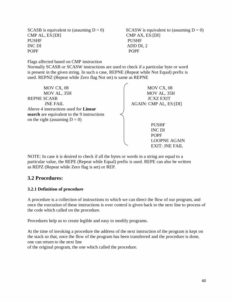
SCASB is equivalent to (assuming D = 0) SCASW is equivalent to (assuming D = 0)
CMP AL, ES:[DI] CMP AX, ES:[DI]
PUSHF PUSHF
INC DI ADD DI, 2
POPF POPF
Flags affected based on CMP instruction
Normally SCASB or SCASW instructions are used to check if a particular byte or word
is present in the given string. In such a case, REPNE (Repeat while Not Equal) prefix is
used. REPNZ (Repeat while Zero flag Not set) is same as REPNE
MOV CX, 08 MOV CX, 08
MOV AL, 35H MOV AL, 35H
REPNE SCASB JCXZ EXIT
JNE FAIL AGAIN: CMP AL, ES:[DI]
Above 4 instructions used for Linear
search are equivalent to the 9 instructions
on the right (assuming D = 0)
PUSHF
INC DI
POPF
LOOPNE AGAIN
EXIT: JNE FAIL
NOTE: In case it is desired to check if all the bytes or words in a string are equal to a
particular value, the REPE (Repeat while Equal) prefix is used. REPE can also be written
as REPZ (Repeat while Zero flag is set) or REP.
3.2 Procedures:
3.2.1 Definition of procedure
A procedure is a collection of instructions to which we can direct the flow of our program, and
once the execution of these instructions is over control is given back to the next line to process of
the code which called on the procedure.
Procedures help us to create legible and easy to modify programs.
At the time of invoking a procedure the address of the next instruction of the program is kept on
the stack so that, once the flow of the program has been transferred and the procedure is done,
one can return to the next line
of the original program, the one which called the procedure.

41
3.2.2 Syntax of a Procedure
There are two types of procedures, the intrasegments, which are found on the same segment of
instructions, and the inter-segments which can be stored on different memory segments.
When the intrasegment procedures are used, the value of IP is stored on the stack and when the
intrasegments are used the value of CS:IP is stored.
To divert the flow of a procedure (calling it), the following directive is used:
CALL NameOfTheProcedure
The part which make a procedure are:
Declaration of the procedure
Code of the procedure
Return directive
Termination of the procedure
For example, if we want a routine which adds two bytes stored in AH and AL
each one, and keep the addition in the BX register:
Adding Proc Near ; Declaration of the procedure
Mov Bx, 0 ; Content of the procedure
Mov B1, Ah
Mov Ah, 00
Add Bx, Ax
Ret ; Return directive
Add Endp ; End of procedure declaration
On the declaration the first word, Adding, corresponds to the name of out
procedure, Proc declares it as such and the word Near indicates to the MASM
that the procedure is intrasegment.
The Ret directive loads the IP address stored on the stack to return to the original program, lastly,
the Add Endp directive indicates the end of the procedure.
To declare an inter segment procedure we substitute the word Near for the
word FAR.
The calling of this procedure is done the following way:
Call Adding
Macros offer a greater flexibility in programming compared to the
procedures, nonetheless, these last ones will still be used.

42
3.3 Macros
Definition of the macro
A macro is a gro of repetitive instructions in a program which are
codified only once and can be used as many times as necessary.
The main difference between a macro and a procedure is that in the macro
the passage of parameters is possible and in the procedure it is not, this
is only applicable for the TASM - there are other programming languages
which do allow it. At the moment the macro is executed each parameter is
substituted by the name or value specified at the time of the call.
We can say then that a procedure is an extension of a determined program,
while the macro is a module with specific functions which can be used by
different programs.
Another difference between a macro and a procedure is the way of calling
each one, to call a procedure the use of a directive is required, on the
other hand the call of macros is done as if it were an assembler
instruction.
Syntax of a Macro
The parts which make a macro are:
Declaration of the macro
Code of the macro
Macro termination directive
The declaration of the macro is done the following way:
NameMacro MACRO [parameter1, parameter2...]
Even though we have the functionality of the parameters it is possible to
create a macro which does not need them.
The directive for the termination of the macro is: ENDM
An example of a macro, to place the cursor on a determined position on the
screen is:
Position MACRO Row, Column
PUSH AX
PUSH BX
PUSH DX
43
MOV AH, 02H
MOV DH, Row
MOV DL, Column
MOV BH, 0
INT 10H
POP DX
POP BX
POP AX
ENDM
To use a macro it is only necessary to call it by its name, as if it were
another assembler instruction, since directives are no longer necessary as
in the case of the procedures. Example:
Position 8, 6
Macro Libraries
One of the facilities that the use of macros offers is the creation of
libraries, which are groups of macros which can be included in a program
from a different file.
The creation of these libraries is very simple, we only have to write a
file with all the macros which will be needed and save it as a text file.
To call these macros it is only necessary to use the following instruction
Include NameOfTheFile, on the part of our program where we would normally
write the macros, this is, at the beginning of our program, before the
declaration of the memory model.
The macros file was saved with the name of MACROS.TXT, the
instruction Include would be used the following way:
;Beginning of the program
Include MACROS.TXT
.MODEL SMALL
.DATA
;The data goes here
.CODE
Beginning:
;The code of the program is inserted here
.STACK
;The stack is defined
End beginning
;Our program ends

44
UNIT-4 8086 instruction descriptions and assembler directives,Instruction descriptions, assembler
directives , DB, DD, DQ, DT,DW, end-program, endp,ends, equ ,even-align on even memory
address, extrn , global, public / extrn, group, include,label,length- not implemented IBM MASM,
name – off set, ORG, proc, ptr, segment, short,type.
8086 INSTRUCTION SET : 4.1 DATA TRANSFER INSTRUCTIONS
4.1.1 MOV – MOV Destination, Source
The MOV instruction copies a word or byte of data from a specified source to a specified
destination. The destination can be a register or a memory location. The source can be a register,
a memory location or an immediate number. The source and destination cannot both be memory
locations. They must both be of the same type (bytes or words). MOV instruction does not affect
any flag.
MOV CX, 037AH Put immediate number 037AH to CX
MOV BL, [437AH] Copy byte in DS at offset 437AH to BL
MOV AX, BX Copy content of register BX to AX
MOV DL, [BX] Copy byte from memory at [BX] to DL
MOV DS, BX Copy word from BX to DS register
MOV RESULT [BP], AX Copy AX to two memory locations; AL to the first
location, AH to the second; EA of the first memory
location is sum of the displacement represented by
RESULTS and content of BP. Physical address = EA + SS.
MOV ES: RESULTS [BP], AX Same as the above instruction, but physical address = EA
+ ES,because of the segment override prefix ES
4.1.2 XCHG – XCHG Destination, Source
The XCHG instruction exchanges the content of a register with the content of another register or
with the content of memory location(s). It cannot directly exchange the content of two memory
locations. The source and destination must both be of the same type (bytes or words). The
segment registers cannot be used in this instruction. This instruction does not affect any flag.
XCHG AX, DX Exchange word in AX with word in DX
XCHG BL, CH Exchange byte in BL with byte in CH
XCHG AL, PRICES [BX] Exchange byte in AL with byte in memory at EA = PRICE
[BX] in DS.
4.1.3 LEA – LEA Register, Source
This instruction determines the offset of the variable or memory location named as the source
and puts this offset in the indicated 16-bit register. LEA does not affect any flag.
LEA BX, PRICES Load BX with offset of PRICE in DS
LEA BP, SS: STACK_TOP Load BP with offset of STACK_TOP in SS
LEA CX, [BX][DI] Load CX with EA = [BX] + [DI]
45
4.1.4 LDS – LDS Register, Memory address of the first word This instruction loads new values into the specified register and into the DS register from four
successive memory locations. The word from two memory locations is copied into the specified
register and the word from the next two memory locations is copied into the DS registers. LDS
does not affect any flag.
LDS BX, [4326] Copy content of memory at displacement 4326H in DS to BL,content
of 4327H to BH. Copy content at displacement of 4328H and 4329H in DS to DS
register.
LDS SI, SPTR Copy content of memory at displacement SPTR and SPTR + 1 , in DS to
SI register. Copy content of memory at displacements SPTR + 2 and SPTR + 3 in DS to
DS register. DS: SI now points at start of the desired string.
4.1.5 LES – LES Register, Memory address of the first word
This instruction loads new values into the specified register and into the ES register from four
successive memory locations. The word from the first two memory locations is copied into the
specified register, and the word from the next two memory locations is copied into the ES
register. LES does not affect any flag.
LES BX, [789AH] Copy content of memory at displacement 789AH in DS to BL,content
of 789BH to BH, content of memory at displacement 789CH and 789DH in DS is copied
to ES register.
LES DI, [BX] Copy content of memory at offset [BX] and offset [BX] + 1 in DS to DI
register. Copy content of memory at offset [BX] + 2 and [BX] + 3 to ES register.
4.2 ARITHMETIC INSTRUCTIONS
4.2.1 ADD – ADD Destination, Source
ADC – ADC Destination, Source
These instructions add a number from some source to a number in some destination and put the
result in the specified destination. The ADC also adds the status of the carry flag to the result.
The source may be an immediate number, a register, or a memory location. The destination may
be a register or a memory location. The source and the destination in an instruction cannot both
be memory locations. The source and the destination must be of the same type (bytes or words).
If you want to add a byte to a word, you must copy the byte to a word location and fill the upper
byte of the word with 0’s before adding. Flags affected: AF, CF, OF, SF, ZF.
ADD AL, 74H Add immediate number 74H to content of AL.
Result in AL
ADC CL, BL Add content of BL plus carry status to content of CL
ADD DX, BX Add content of BX to content of DX
Ex: ADD DX, [SI] Add word from memory at offset [SI] in DS to
content of DX
Ex: ADC AL, PRICES [BX] Add byte from effective address PRICES
[BX] plus carry status
to content of AL
ADD AL, PRICES [BX] Add content of memory at effective address PRICES [BX] to
AL

46
4.2.2 SUB – SUB Destination, Source
SBB – SBB Destination, Source
These instructions subtract the number in some source from the number in some destination and
put the result in the destination. The SBB instruction also subtracts the content of carry flag from
the destination. The source may be an immediate number, a register or memory location. The
destination can also be a register or a memory location. However, the source and the destination
cannot both be memory location. The source and the destination must both be of the same type
(bytes or words). If you want to subtract a byte from a word, you must first move the byte to a
word location such as a 16-bit register and fill the upper byte of the word with 0’s. Flags
affected: AF, CF, OF, PF, SF, ZF.
SUB CX, BX CX – BX; Result in CX
SBB CH, AL Subtract content of AL and content of CF from content of CH. Result in
CH
SUB AX, 3427H Subtract immediate number 3427H from AX
SBB BX, [3427H] Subtract word at displacement 3427H in DS and content of CF from
BX
SUB PRICES [BX], 04H Subtract 04 from byte at effective address PRICES [BX],if
PRICES is declared with DB; Subtract 04 from word at effective address PRICES [BX],
if it is declared with DW.
SBB CX, TABLE [BX] Subtract word from effective address TABLE [BX]and status of
CF from CX.
SBB TABLE [BX], CX Subtract CX and status of CF from word in memory at effective
address TABLE[BX].
4.2.3 MUL – MUL Source
This instruction multiplies an unsigned byte in some source with an unsigned byte in AL register
or an unsigned word in some source with an unsigned word in AX register. The source can be a
register or a memory location. When a byte is multiplied by the content of AL, the result
(product) is put in AX. When a word is multiplied by the content of AX, the result is put in DX
and AX registers. If the most significant byte of a 16-bit result or the most significant word of a
32-bit result is 0, CF and OF will both be 0’s. AF, PF, SF and ZF are undefined after a MUL
instruction.
If you want to multiply a byte with a word, you must first move the byte to a word location such
as an extended register and fill the upper byte of the word with all 0’s. You cannot use the CBW
instruction for this, because the CBW instruction fills the upper byte with copies of the most
significant bit of the lower byte.
MUL BH Multiply AL with BH; result in AX
MUL CX Multiply AX with CX; result high word in DX, low word in AX
MUL BYTE PTR [BX] Multiply AL with byte in DS pointed to by [BX]
MUL FACTOR [BX] Multiply AL with byte at effective address FACTOR [BX], if it is
declared as type byte with DB. Multiply AX with word at effective address FACTOR
[BX], if it is declared as type word with DW.
MOV AX, MCAND_16 Load 16-bit multiplicand into AX
MOV CL, MPLIER_8 Load 8-bit multiplier into CL
MOV CH, 00H Set upper byte of CX to all 0’s

47
MUL CX AX times CX; 32-bit result in DX and AX
4.2.4 IMUL – IMUL Source
This instruction multiplies a signed byte from source with a signed byte in AL or a signed word
from some source with a signed word in AX. The source can be a register or a memory location.
When a byte from source is multiplied with content of AL, the signed result (product) will be put
in AX. When a word from source is multiplied by AX, the result is put in DX and AX. If the
magnitude of the product does not require all the bits of the destination, the unused byte / word
will be filled with copies of the sign bit. If the upper byte of a 16-bit result or the upper word of a
32-bit result contains only copies of the sign bit (all 0’s or all 1’s), then CF and the OF will both
be 0; If it contains a part of the product, CF and OF will both be 1. AF, PF, SF and ZF are
undefined after IMUL.
If you want to multiply a signed byte with a signed word, you must first move the byte into a
word location and fill the upper byte of the word with copies of the sign bit. If you move the byte
into AL, you can use the CBW instruction to do this.
IMUL BH Multiply signed byte in AL with signed byte in BH;result in AX.
IMUL AX Multiply AX times AX; result in DX and AX
MOV CX, MULTIPLIER Load signed word in CX
MOV AL, MULTIPLICAND Load signed byte in AL
CBW Extend sign of AL into AH
IMUL CX Multiply CX with AX; Result in DX and AX
4.2.5 DIV – DIV Source
This instruction is used to divide an unsigned word by a byte or to divide an unsigned double
word (32 bits) by a word. When a word is divided by a byte, the word must be in the AX register.
The divisor can be in a register or a memory location. After the division, AL will contain the 8-
bit quotient, and AH will contain the 8-bit remainder. When a double word is divided by a word,
the most significant word of the double word must be in DX, and the least significant word of the
double word must be in AX. After the division, AX will contain the 16-bit quotient and DX will
contain the 16-bit remainder. If an attempt is made to divide by 0 or if the quotient is too large to
fit in the destination (greater than FFH / FFFFH), the 8086 will generate a type 0 interrupt. All
flags are undefined after a DIV instruction.
If you want to divide a byte by a byte, you must first put the dividend byte in AL and fill AH
with all 0’s. Likewise, if you want to divide a word by another word, then put the dividend word
in AX and fill DX with all 0’s.
DIV BL Divide word in AX by byte in BL; Quotient in AL, remainder in AH
DIV CX Divide down word in DX and AX by word in CX; Quotient in AX, and
remainder in DX.
DIV SCALE [BX] AX / (byte at effective address SCALE [BX]) if SCALE [BX] is of
type byte; or (DX and AX) / (word at effective address SCALE[BX] if SCALE[BX] is of
type word
48
4.2.6 IDIV – IDIV Source This instruction is used to divide a signed word by a signed byte, or to divide a signed double
word by a signed word.
When dividing a signed word by a signed byte, the word must be in the AX register. The divisor
can be in an 8-bit register or a memory location. After the division, AL will contain the signed
quotient, and AH will contain the signed remainder. The sign of the remainder will be the same
as the sign of the dividend. If an attempt is made to divide by 0, the quotient is greater than 127
(7FH) or less than –127 (81H), the 8086 will automatically generate a type 0 interrupt.
When dividing a signed double word by a signed word, the most significant word of the dividend
(numerator) must be in the DX register, and the least significant word of the dividend must be in
the AX register. The divisor can be in any other 16-bit register or memory location. After the
division, AX will contain a signed 16-bit quotient, and DX will contain a signed 16-bit
remainder. The sign of the remainder will be the same as the sign of the dividend. Again, if an
attempt is made to divide by 0, the quotient is greater than +32,767 (7FFFH) or less than –32,767
(8001H), the 8086 will automatically generate a type 0 interrupt.
All flags are undefined after an IDIV.
If you want to divide a signed byte by a signed byte, you must first put the dividend byte in AL
and sign-extend AL into AH. The CBW instruction can be used for this purpose. Likewise, if
you want to divide a signed word by a signed word, you must put the dividend word in AX and
extend the sign of AX to all the bits of DX. The CWD instruction can be used for this purpose.
IDIV BL Signed word in AX/signed byte in BL
IDIV BP Signed double word in DX and AX/signed word in BP
IDIV BYTE PTR [BX] AX / byte at offset [BX] in DS
4.2.7 INC – INC Destination
The INC instruction adds 1 to a specified register or to a memory location. AF, OF, PF, SF, and
ZF are updated, but CF is not affected. This means that if an 8-bit destination containing FFH or
a 16-bit destination containing FFFFH is incremented, the result will be all 0’s with no carry.
INC BL Add 1 to contains of BL register
INC CX Add 1 to contains of CX register
INC BYTE PTR [BX] Increment byte in data segment at offset contained in BX.
INC WORD PTR [BX] Increment the word at offset of [BX] and [BX + 1] in the data
segment.
INC TEMP Increment byte or word named TEMP in the data segment.
Increment byte if MAX_TEMP declared with DB.
Increment word if MAX_TEMP is declared with DW.
INC PRICES [BX] Increment element pointed to by [BX] in array PRICES.
Increment a word if PRICES is declared as an array of words;
Increment a byte if PRICES is declared as an array of bytes.

49
4.2.8 DEC – DEC Destination
This instruction subtracts 1 from the destination word or byte. The destination can be a register
or a memory location. AF, OF, SF, PF, and ZF are updated, but CF is not affected. This means
that if an 8-bit destination containing 00H or a 16-bit destination containing 0000H is
decremented, the result will be FFH or FFFFH with no carry (borrow).
DEC CL Subtract 1 from content of CL register
DEC BP Subtract 1 from content of BP register
DEC BYTE PTR [BX] Subtract 1 from byte at offset [BX] in DS.
DEC WORD PTR [BP] Subtract 1 from a word at offset [BP] in SS.
DEC COUNT Subtract 1 from byte or word named COUNT in DS.
Decrement a byte if COUNT is declared with a DB;
Decrement a word if COUNT is declared with a DW.
4.2.9 DAA (DECIMAL ADJUST AFTER BCD ADDITION)
This instruction is used to make sure the result of adding two packed BCD numbers is adjusted
to be a legal BCD number. The result of the addition must be in AL for DAA to work correctly.
If the lower nibble in AL after an addition is greater than 9 or AF was set by the addition, then
the DAA instruction will add 6 to the lower nibble in AL. If the result in the upper nibble of AL
in now greater than 9 or if the carry flag was set by the addition or correction, then the DAA
instruction will add 60H to AL.
Let AL = 59 BCD, and BL = 35 BCD
ADD AL, BL AL = 8EH; lower nibble > 9, add 06H to AL
DAA AL = 94 BCD, CF = 0
Let AL = 88 BCD, and BL = 49 BCD
ADD AL, BL AL = D1H; AF = 1, add 06H to AL
DAA AL = D7H; upper nibble > 9, add 60H to AL
AL = 37 BCD, CF = 1
The DAA instruction updates AF, CF, SF, PF, and ZF; but OF is undefined.
4.2.10 DAS (DECIMAL ADJUST AFTER BCD SUBTRACTION)
This instruction is used after subtracting one packed BCD number from another packed BCD
number, to make sure the result is correct packed BCD. The result of the subtraction must be in
AL for DAS to work correctly. If the lower nibble in AL after a subtraction is greater than 9 or
the AF was set by the subtraction, then the DAS instruction will subtract 6 from the lower nibble
AL. If the result in the upper nibble is now greater than 9 or if the carry flag was set, the DAS
instruction will subtract 60 from AL.
Ex: Let AL = 86 BCD, and BH = 57 BCD
SUB AL, BH AL = 2FH; lower nibble > 9, subtract 06H from AL
AL = 29 BCD, CF = 0
Ex: Let AL = 49 BCD, and BH = 72 BCD

50
SUB AL, BH AL = D7H; upper nibble > 9, subtract 60H from AL
DAS AL = 77 BCD, CF = 1 (borrow is needed)
The DAS instruction updates AF, CF, SF, PF, and ZF; but OF is undefined.
4.2.11 CBW (CONVERT SIGNED BYTE TO SIGNED WORD) This instruction copies the sign bit of the byte in AL to all the bits in AH. AH is then said to be
the sign extension of AL. CBW does not affect any flag.
Ex: Let AX = 00000000 10011011 (–155 decimal)
CBW Convert signed byte in AL to signed word in AX
AX = 11111111 10011011 (–155 decimal)
4.2.12 CWD (CONVERT SIGNED WORD TO SIGNED DOUBLE WORD)
This instruction copies the sign bit of a word in AX to all the bits of the DX register. In other
words, it extends the sign of AX into all of DX. CWD affects no flags.
Ex: Let DX = 00000000 00000000, and AX = 11110000 11000111 (–3897 decimal)
CWD Convert signed word in AX to signed double word in DX:AX
DX = 11111111 11111111
AX = 11110000 11000111 (–3897 decimal)
4.2.13 AAA (ASCII ADJUST FOR ADDITION)
Numerical data coming into a computer from a terminal is usually in ASCII code. In this code,
the numbers 0 to 9 are represented by the ASCII codes 30H to 39H. The 8086 allows you to add
the ASCII codes for two decimal digits without masking off the “3” in the upper nibble of each.
After the addition, the AAA instruction is used to make sure the result is the correct unpacked
BCD.
Ex: Let AL = 0011 0101 (ASCII 5), and BL = 0011 1001 (ASCII 9)
ADD AL, BL AL = 0110 1110 (6EH, which is incorrect BCD)
AAA AL = 0000 0100 (unpacked BCD 4)
CF = 1 indicates answer is 14 decimal.
The AAA instruction works only on the AL register. The AAA instruction updates AF and CF;
but OF, PF, SF and ZF are left undefined.
4.2.14 AAS (ASCII ADJUST FOR SUBTRACTION) Numerical data coming into a computer from a terminal is usually in an ASCII code. In this code
the numbers 0 to 9 are represented by the ASCII codes 30H to 39H. The 8086 allows you to
subtract the ASCII codes for two decimal digits without masking the “3” in the upper nibble of
each. The AAS instruction is then used to make sure the result is the correct unpacked BCD.
Ex: Let AL = 00111001 (39H or ASCII 9), and BL = 00110101 (35H or ASCII 5)
SUB AL, BL AL = 00000100 (BCD 04), and CF = 0
AAS AL = 00000100 (BCD 04), and CF = 0 (no borrow required)
Ex: Let AL = 00110101 (35H or ASCII 5), and BL = 00111001 (39H or ASCII 9)
SUB AL, BL AL = 11111100 (– 4 in 2’s complement form), and CF = 1
AAS AL = 00000100 (BCD 06), and CF = 1 (borrow required)
The AAS instruction works only on the AL register. It updates ZF and CF; but OF, PF, SF, AF
are left undefined.
51
4.2.14 AAM (BCD ADJUST AFTER MULTIPLY) Before you can multiply two ASCII digits, you must first mask the upper 4 bit of each. This
leaves unpacked BCD (one BCD digit per byte) in each byte. After the two unpacked BCD digits
are multiplied, the AAM instruction is used to adjust the product to two unpacked BCD digits in
AX. AAM works only after the multiplication of two unpacked BCD bytes, and it works only the
operand in AL. AAM updates PF, SF and ZF but AF; CF and OF are left undefined.
Ex: Let AL = 00000101 (unpacked BCD 5), and BH = 00001001 (unpacked BCD 9)
MUL BH AL x BH: AX = 00000000 00101101 = 002DH
AAM AX = 00000100 00000101 = 0405H (unpacked BCD for 45)
4.2.15 AAD (BCD-TO-BINARY CONVERT BEFORE DIVISION) AAD converts two unpacked BCD digits in AH and AL to the equivalent binary number in AL.
This adjustment must be made before dividing the two unpacked BCD digits in AX by an
unpacked BCD byte. After the BCD division, AL will contain the unpacked BCD quotient and
AH will contain the unpacked BCD remainder. AAD updates PF, SF and ZF; AF, CF and OF are
left undefined.
Ex: Let AX = 0607 (unpacked BCD for 67 decimal), and CH = 09H
AAD AX = 0043 (43H = 67 decimal)
DIV CH AL = 07; AH = 04; Flags undefined after DIV
If an attempt is made to divide by 0, the 8086 will generate a type 0 interrupt.
LOGICAL INSTRUCTIONS
4.2.16 AND – AND Destination, Source This instruction ANDs each bit in a source byte or word with the same numbered bit in a
destination byte or word. The result is put in the specified destination. The content of the
specified source is not changed.
The source can be an immediate number, the content of a register, or the content of a memory
location. The destination can be a register or a memory location. The source and the destination
cannot both be memory locations. CF and OF are both 0 after AND. PF, SF, and ZF are updated
by the AND instruction. AF is undefined. PF has meaning only for an 8-bit operand.
Ex: AND CX, [SI] AND word in DS at offset [SI] with word in CX register;
Result in CX register
Ex: AND BH, CL AND byte in CL with byte in BH; Result in BH
Ex: AND BX, 00FFH 00FFH Masks upper byte, leaves lower byte unchanged.
4.2.17 OR – OR Destination, Source This instruction ORs each bit in a source byte or word with the same numbered bit in a
destination byte or word. The result is put in the specified destination. The content of the
specified source is not changed.
The source can be an immediate number, the content of a register, or the content of a memory
location. The destination can be a register or a memory location. The source and destination
cannot both be memory locations. CF and OF are both 0 after OR. PF, SF, and ZF are updated by
the OR instruction. AF is undefined. PF has meaning only for an 8-bit operand.
Ex: OR AH, CL CL ORed with AH, result in AH, CL not changed
Ex: OR BP, SI SI ORed with BP, result in BP, SI not changed

52
Ex: OR SI, BP BP ORed with SI, result in SI, BP not changed
Ex: OR BL, 80H BL ORed with immediate number 80H; sets MSB of BL to 1
Ex: OR CX, TABLE [SI] CX ORed with word from effective address TABLE [SI];
Content of memory is not changed.
4.2.18 XOR – XOR Destination, Source This instruction Exclusive-ORs each bit in a source byte or word with the same numbered bit in
a destination byte or word. The result is put in the specified destination. The content of the
specified source is not changed.
The source can be an immediate number, the content of a register, or the content of a memory
location. The destination can be a register or a memory location. The source and destination
cannot both be memory locations. CF and OF are both 0 after XOR. PF, SF, and ZF are updated.
PF has meaning only for an 8-bit operand. AF is undefined.
Ex: XOR CL, BH Byte in BH exclusive-ORed with byte in CL.
Result in CL. BH not changed.
Ex: XOR BP, DI Word in DI exclusive-ORed with word in BP.
Result in BP. DI not changed.
Ex: XOR WORD PTR [BX], 00FFH Exclusive-OR immediate number 00FFH with word at
offset [BX] in the data segment.
Result in memory location [BX]
4.2.19 NOT – NOT Destination
The NOT instruction inverts each bit (forms the 1’s complement) of a byte or word in the
specified destination. The destination can be a register or a memory location. This instruction
does not affect any flag.
Ex: NOT BX Complement content or BX register
Ex: NOT BYTE PTR [BX] Complement memory byte at offset [BX] in data segment.
4.2.20 NEG – NEG Destination This instruction replaces the number in a destination with its 2’s complement. The destination
can be a register or a memory location. It gives the same result as the invert each bit and add one
algorithm. The NEG instruction updates AF, AF, PF, ZF, and OF.
Ex: NEG AL Replace number in AL with its 2’s complement
Ex: NEG BX Replace number in BX with its 2’s complement
Ex: NEG BYTE PTR [BX] Replace byte at offset BX in DX with its 2’s complement
Ex: NEG WORD PTR [BP] Replace word at offset BP in SS with its 2’s complement
4.2.21 CMP – CMP Destination, Source This instruction compares a byte / word in the specified source with a byte / word in the specified
destination. The source can be an immediate number, a register, or a memory location. The
destination can be a register or a memory location. However, the source and the destination
cannot both be memory locations. The comparison is actually done by subtracting the source
byte or word from the destination byte or word. The source and the destination are not changed,
but the flags are set to indicate the results of the comparison. AF, OF, SF, ZF, PF, and CF are
updated by the CMP instruction. For the instruction CMP CX, BX, the values of CF, ZF, and SF
will be as follows:
53
CF ZF SF
CX = BX 0 1 0 Result of subtraction is 0
CX > BX 0 0 0 No borrow required, so CF = 0
CX < BX 1 0 1 Subtraction requires borrow, so CF = 1
Ex: CMP AL, 01H Compare immediate number 01H with byte in AL
Ex: CMP BH, CL Compare byte in CL with byte in BH
Ex: CMP CX, TEMP Compare word in DS at displacement TEMP with word at CX
Ex: CMP PRICES [BX], 49H Compare immediate number 49H with byte at offset [BX]in array
PRICES
4.2.22 TEST – TEST Destination, Source
This instruction ANDs the byte / word in the specified source with the byte / word in the
specified destination. Flags are updated, but neither operand is changed. The test instruction is
often used to set flags before a Conditional jump instruction.
The source can be an immediate number, the content of a register, or the content of a memory
location. The destination can be a register or a memory location. The source and the destination
cannot both be memory locations. CF and OF are both 0’s after TEST. PF, SF and ZF will be
updated to show the results of the destination. AF is be undefined.
Ex: TEST AL, BH AND BH with AL. No result stored; Update PF, SF, ZF.
Ex: TEST CX, 0001H AND CX with immediate number 0001H;
No result stored; Update PF, SF, ZF
Ex: TEST BP, [BX][DI] AND word are offset [BX][DI] in DS with word in BP.
No result stored. Update PF, SF, and ZF
ROTATE AND SHIFT INSTRUCTIONS
4.2.23 RCL – RCL Destination, Count
This instruction rotates all the bits in a specified word or byte some number of bit positions to the
left. The operation circular because the MSB of the operand is rotated into the carry flag and the
bit in the carry flag is rotated around into LSB of the operand.
CF MSB LSB
For multi-bit rotates, CF will contain the bit most recently rotated out of the MSB.
The destination can be a register or a memory location. If you want to rotate the operand by one
bit position, you can specify this by putting a 1 in the count position of the instruction. To rotate
by more than one bit position, load the desired number into the CL register and put “CL” in the
count position of the instruction.
RCL affects only CF and OF. OF will be a 1 after a single bit RCL if the MSB was changed by
the rotate. OF is undefined after the multi-bit rotate.
Ex: RCL DX, 1 Word in DX 1 bit left, MSB to CF, CF to LSB
Ex: MOV CL, 4 Load the number of bit positions to rotate into CL
RCL SUM [BX], CL Rotate byte or word at effective address SUM [BX] 4 bits left
Original bit 4 now in CF, original CF now in bit 3.
4.2.24 RCR – RCR Destination, Count
This instruction rotates all the bits in a specified word or byte some number of bit positions to the
right. The operation circular because the LSB of the operand is rotated into the carry flag and the
bit in the carry flag is rotate around into MSB of the operand.

54
CF MSB LSB
For multi-bit rotate, CF will contain the bit most recently rotated out of the LSB.
The destination can be a register or a memory location. If you want to rotate the operand by one
bit position, you can specify this by putting a 1 in the count position of the instruction. To rotate
more than one bit position, load the desired number into the CL register and put “CL” in the
count position of the instruction.
RCR affects only CF and OF. OF will be a 1 after a single bit RCR if the MSB was changed by
the rotate. OF is undefined after the multi-bit rotate.
Ex: RCR BX, 1 Word in BX right 1 bit, CF to MSB, LSB to CF
Ex: MOV CL, 4 Load CL for rotating 4 bit position
RCR BYTE PTR [BX], 4 Rotate the byte at offset [BX] in DS 4 bit positions right
CF = original bit 3, Bit 4 – original CF.
4.2.25 ROL – ROL Destination, Count This instruction rotates all the bits in a specified word or byte to the left some number of bit
positions. The data bit rotated out of MSB is circled back into the LSB. It is also copied into CF.
In the case of multiple-bit rotate, CF will contain a copy of the bit most recently moved out of
the MSB.
CF MSB LSB
The destination can be a register or a memory location. If you to want rotate the operand by one
bit position, you can specify this by putting 1 in the count position in the instruction. To rotate
more than one bit position, load the desired number into the CL register and put “CL” in the
count position of the instruction.
ROL affects only CF and OF. OF will be a 1 after a single bit ROL if the MSB was changed by
the rotate.
Ex: ROL AX, 1 Rotate the word in AX 1 bit position left, MSB to LSB and CF
Ex: MOV CL, 04H Load number of bits to rotate in CL
ROL BL, CL Rotate BL 4 bit positions
Ex: ROL FACTOR [BX], 1 Rotate the word or byte in DS at EA = FACTOR [BX] by 1 bit
position left into CF
4.2.26 ROR – ROR Destination, Count
This instruction rotates all the bits in a specified word or byte some number of bit positions to
right. The operation is desired as a rotate rather than shift, because the bit moved out of the LSB
is rotated around into the MSB. The data bit moved out of the LSB is also copied into CF. In the
case of multiple bit rotates, CF will contain a copy of the bit most recently moved out of the
LSB.
CF MSB LSB
The destination can be a register or a memory location. If you want to rotate the operand by one
bit position, you can specify this by putting 1 in the count position in the instruction. To rotate by
more than one bit position, load the desired number into the CL register and put “CL” in the
count position of the instruction.

55
ROR affects only CF and OF. OF will be a 1 after a single bit ROR if the MSB was changed by
the rotate.
Ex: ROR BL, 1 Rotate all bits in BL right 1 bit position LSB to MSB and to CF
Ex: MOV CL, 08H Load CL with number of bit positions to be rotated
ROR WORD PTR [BX], CL Rotate word in DS at offset [BX] 8 bit position right
4.2.27 SAL – SAL Destination, Count
SHL – SHL Destination, Count
SAL and SHL are two mnemonics for the same instruction. This instruction shifts each bit in the
specified destination some number of bit positions to the left. As a bit is shifted out of the LSB
operation, a 0 is put in the LSB position. The MSB will be shifted into CF. In the case of multi-
bit shift, CF will contain the bit most recently shifted out from the MSB. Bits shifted into CF
previously will be lost.
CF MSB LSB 0
The destination operand can be a byte or a word. It can be in a register or in a memory location.
If you want to shift the operand by one bit position, you can specify this by putting a 1 in the
count position of the instruction. For shifts of more than 1 bit position, load the desired number
of shifts into the CL register, and put “CL” in the count position of the instruction.
The flags are affected as follow: CF contains the bit most recently shifted out from MSB. For a
count of one, OF will be 1 if CF and the current MSB are not the same. For multiple-bit shifts,
OF is undefined. SF and ZF will be updated to reflect the condition of the destination. PF will
have meaning only for an operand in AL. AF is undefined.
Ex: SAL BX, 1 Shift word in BX 1 bit position left, 0 in LSB
Ex: MOV CL, 02h Load desired number of shifts in CL
SAL BP, CL Shift word in BP left CL bit positions, 0 in LSBs
Ex: SAL BYTE PTR [BX], 1 Shift byte in DX at offset [BX] 1 bit position left, 0 in LSB
4.2.28 SAR – SAR Destination, Count
This instruction shifts each bit in the specified destination some number of bit positions to the
right. As a bit is shifted out of the MSB position, a copy of the old MSB is put in the MSB
position. In other words, the sign bit is copied into the MSB. The LSB will be shifted into CF. In
the case of multiple-bit shift, CF will contain the bit most recently shifted out from the LSB. Bits
shifted into CF previously will be lost.
MSB MSB LSB CF
The destination operand can be a byte or a word. It can be in a register or in a memory location.
If you want to shift the operand by one bit position, you can specify this by putting a 1 in the
count position of the instruction. For shifts of more than 1 bit position, load the desired number
of shifts into the CL register, and put “CL” in the count position of the instruction.
The flags are affected as follow: CF contains the bit most recently shifted in from LSB. For a
count of one, OF will be 1 if the two MSBs are not the same. After a multi-bit SAR, OF will be
0. SF and ZF will be updated to show the condition of the destination. PF will have meaning only
for an 8- bit destination. AF will be undefined after SAR.
Ex: SAR DX, 1 Shift word in DI one bit position right, new MSB = old MSB
Ex: MOV CL, 02H Load desired number of shifts in CL
SAR WORD PTR [BP], CL Shift word at offset [BP] in stack segment right by two bit positions,
the two MSBs are now copies of original LSB

56
4.2.29 SHR – SHR Destination, Count This instruction shifts each bit in the specified destination some number of bit positions to the
right. As a bit is shifted out of the MSB position, a 0 is put in its place. The bit shifted out of the
LSB position goes to CF. In the case of multi-bit shifts, CF will contain the bit most recently
shifted out from the LSB. Bits shifted into CF previously will be lost.
0 MSB LSB CF
The destination operand can be a byte or a word in a register or in a memory location. If you
want to shift the operand by one bit position, you can specify this by putting a 1 in the count
position of the instruction. For shifts of more than 1 bit position, load the desired number of
shifts into the CL register, and put “CL” in the count position of the instruction.
The flags are affected by SHR as follow: CF contains the bit most recently shifted out from LSB.
For a count of one, OF will be 1 if the two MSBs are not both 0’s. For multiple-bit shifts, OF
will be meaningless. SF and ZF will be updated to show the condition of the destination. PF will
have meaning only for an 8-bit destination. AF is undefined.
Ex: SHR BP, 1 Shift word in BP one bit position right, 0 in MSB
Ex: MOV CL, 03H Load desired number of shifts into CL
SHR BYTE PTR [BX] Shift byte in DS at offset [BX] 3 bits right; 0’s in 3 MSBs
TRANSFER-OF-CONTROL INSTRUCTIONS
Note: The following rules apply to the discussions presented in this section.
The terms above and below are used when referring to the magnitude of unsigned
numbers. For example, the number 00000111 (7) is above the number 00000010 (2),
whereas the number 00000100 (4) is below the number 00001110 (14).
The terms greater and less are used to refer to the relationship of two signed numbers.
Greater means more positive. The number 00000111 (+7) is greater than the number
11111110 (-2), whereas the number 11111100 (-4) is less than the number 11110100 (-
6).
In the case of Conditional jump instructions, the destination address must be in the range
of –128 bytes to +127 bytes from the address of the next instruction
These instructions do not affect any flags.
4.2.30 JMP (UNCONDITIONAL JUMP TO SPECIFIED DESTINATION)
This instruction will fetch the next instruction from the location specified in the instruction rather
than from the next location after the JMP instruction. If the destination is in the same code
segment as the JMP instruction, then only the instruction pointer will be changed to get the
destination location. This is referred to as a near jump. If the destination for the jump instruction
is in a segment with a name different from that of the segment containing the JMP instruction,
then both the instruction pointer and the code segment register content will be changed to get the
destination location. This referred to as a far jump. The JMP instruction does not affect any flag.
Ex: JMP CONTINUE
This instruction fetches the next instruction from address at label CONTINUE. If the label is in
the same segment, an offset coded as part of the instruction will be added to the instruction
pointer to produce the new fetch address. If the label is another segment, then IP and CS will be
replaced with value coded in part of the instruction. This type of jump is referred to as direct
because the displacement of the destination or the destination itself is specified directly in the
instruction.

57
Ex: JMP BX
This instruction replaces the content of IP with the content of BX. BX must first be loaded with
the offset of the destination instruction in CS. This is a near jump. It is also referred to as an
indirect jump because the new value of IP comes from a register rather than from the instruction
itself, as in a direct jump.
Ex: JMP WORD PTR [BX]
This instruction replaces IP with word from a memory location pointed to by BX in DX. This is
an indirect near jump.
Ex: JMP DWORD PTR [SI]
This instruction replaces IP with word pointed to by SI in DS. It replaces CS with a word pointed
by SI + 2 in DS. This is an indirect far jump.
4.2.31 JA / JNBE (JUMP IF ABOVE / JUMP IF NOT BELOW OR EQUAL)
If, after a compare or some other instructions which affect flags, the zero flag and the carry flag
both are 0, this instruction will cause execution to jump to a label given in the instruction. If CF
and ZF are not both 0, the instruction will have no effect on program execution.
Ex: CMP AX, 4371H Compare by subtracting 4371H from AX
JA NEXT Jump to label NEXT if AX above 4371H
Ex: CMP AX, 4371H Compare (AX – 4371H)
JNBE NEXT Jump to label NEXT if AX not below or equal to 4371H
4.2.32 JAE / JNB / JNC
(JUMP IF ABOVE OR EQUAL / JUMP IF NOT BELOW / JUMP IF NO CARRY) If, after a compare or some other instructions which affect flags, the carry flag is 0, this
instruction will cause execution to jump to a label given in the instruction. If CF is 1, the
instruction will have no effect on program execution.
Ex: CMP AX, 4371H Compare (AX – 4371H)
JAE NEXT Jump to label NEXT if AX above 4371H
Ex: CMP AX, 4371H Compare (AX – 4371H)
JNB NEXT Jump to label NEXT if AX not below 4371H
Ex: ADD AL, BL Add two bytes
JNC NEXT If the result with in acceptable range, continue
4.2.33 JB / JC / JNAE (JUMP IF BELOW / JUMP IF CARRY / JUMP IF NOT ABOVE
OR EQUAL)
If, after a compare or some other instructions which affect flags, the carry flag is a 1, this
instruction will cause execution to jump to a label given in the instruction. If CF is 0, the
instruction will have no effect on program execution.
Ex: CMP AX, 4371H Compare (AX – 4371H)
JB NEXT Jump to label NEXT if AX below 4371H
Ex: ADD BX, CX Add two words
JC NEXT Jump to label NEXT if CF = 1
Ex: CMP AX, 4371H Compare (AX – 4371H)
JNAE NEXT Jump to label NEXT if AX not above or equal to 4371H
4.2.34 JBE / JNA (JUMP IF BELOW OR EQUAL / JUMP IF NOT ABOVE)
If, after a compare or some other instructions which affect flags, either the zero flag or the carry
flag is 1, this instruction will cause execution to jump to a label given in the instruction. If CF
and ZF are both 0, the instruction will have no effect on program execution.
Ex: CMP AX, 4371H Compare (AX – 4371H)

58
JBE NEXT Jump to label NEXT if AX is below or equal to 4371H
Ex: CMP AX, 4371H Compare (AX – 4371H)
JNA NEXT Jump to label NEXT if AX not above 4371H
4.2.35 JG / JNLE (JUMP IF GREATER / JUMP IF NOT LESS THAN OR EQUAL)
This instruction is usually used after a Compare instruction. The instruction will cause a jump to
the label given in the instruction, if the zero flag is 0 and the carry flag is the same as the
overflow flag.
Ex: CMP BL, 39H Compare by subtracting 39H from BL
JG NEXT Jump to label NEXT if BL more positive than 39H
Ex: CMP BL, 39H Compare by subtracting 39H from BL
JNLE NEXT Jump to label NEXT if BL is not less than or equal to 39H
4.2.36 JGE / JNL (JUMP IF GREATER THAN OR EQUAL / JUMP IF NOT LESS
THAN) This instruction is usually used after a Compare instruction. The instruction will cause a jump to
the label given in the instruction, if the sign flag is equal to the overflow flag.
Ex: CMP BL, 39H Compare by subtracting 39H from BL
JGE NEXT Jump to label NEXT if BL more positive than or equal to 39H
Ex: CMP BL, 39H Compare by subtracting 39H from BL
JNL NEXT Jump to label NEXT if BL not less than 39H
4.2.37 JL / JNGE (JUMP IF LESS THAN / JUMP IF NOT GREATER THAN OR
EQUAL) This instruction is usually used after a Compare instruction. The instruction will cause a jump to
the label given in the instruction if the sign flag is not equal to the overflow flag.
Ex: CMP BL, 39H Compare by subtracting 39H from BL
JL AGAIN Jump to label AGAIN if BL more negative than 39H
Ex: CMP BL, 39H Compare by subtracting 39H from BL
JNGE AGAIN Jump to label AGAIN if BL not more positive than or equal to
39H
4.2.38 JLE / JNG (JUMP IF LESS THAN OR EQUAL / JUMP IF NOT GREATER) This instruction is usually used after a Compare instruction. The instruction will cause a jump to
the label given in the instruction if the zero flag is set, or if the sign flag not equal to the overflow
flag.
Ex: CMP BL, 39H Compare by subtracting 39H from BL
JLE NEXT Jump to label NEXT if BL more negative than or equal to 39H
Ex: CMP BL, 39H Compare by subtracting 39H from BL
JNG NEXT Jump to label NEXT if BL not more positive than 39H
4.2.39 JE / JZ (JUMP IF EQUAL / JUMP IF ZERO) This instruction is usually used after a Compare instruction. If the zero flag is set, then this
instruction will cause a jump to the label given in the instruction.
Ex: CMP BX, DX Compare (BX-DX)
JE DONE Jump to DONE if BX = DX
Ex: IN AL, 30H Read data from port 8FH
SUB AL, 30H Subtract the minimum value.
JZ START Jump to label START if the result of subtraction is 0

59
4.2.40 JNE / JNZ (JUMP NOT EQUAL / JUMP IF NOT ZERO) This instruction is usually used after a Compare instruction. If the zero flag is 0, then this
instruction will cause a jump to the label given in the instruction.
Ex: IN AL, 0F8H Read data value from port
CMP AL, 72 Compare (AL –72)
JNE NEXT Jump to label NEXT if ALNOT EQUAL TO 72
Ex: ADD AX, 0002H Add count factor 0002H to AX
DEC BX Decrement BX
JNZ NEXT Jump to label NEXT if BX NOT EQUAL TO 0
4.2.41 JS (JUMP IF SIGNED / JUMP IF NEGATIVE)
This instruction will cause a jump to the specified destination address if the sign flag is set. Since
a 1 in the sign flag indicates a negative signed number, you can think of this instruction as saying
“jump if negative”.
Ex: ADD BL, DH Add signed byte in DH to signed byte in DL
JS NEXT Jump to label NEXT if result of addition is negative number
4.2.42 JNS (JUMP IF NOT SIGNED / JUMP IF POSITIVE)
This instruction will cause a jump to the specified destination address if the sign flag is 0. Since a
0 in the sign flag indicate a positive signed number, you can think to this instruction as saying
“jump if positive”.
Ex: DEC AL Decrement AL
JNS NEXT Jump to label NEXT if AL has not decremented to FFH
4.2.43 JP / JPE (JUMP IF PARITY / JUMP IF PARITY EVEN)
If the number of 1’s left in the lower 8 bits of a data word after an instruction which affects the
parity flag is even, then the parity flag will be set. If the parity flag is set, the JP / JPE instruction
will cause a jump to the specified destination address.
Ex: IN AL, 0F8H Read ASCII character from Port F8H
OR AL, AL Set flags
JPE ERROR Odd parity expected, send error message if parity found even
4.2.44 JNP / JPO (JUMP IF NO PARITY / JUMP IF PARITY ODD) If the number of 1’s left in the lower 8 bits of a data word after an instruction which affects the
parity flag is odd, then the parity flag is 0. The JNP / JPO instruction will cause a jump to the
specified destination address, if the parity flag is 0.
Ex: IN AL, 0F8H Read ASCII character from Port F8H
OR AL, AL Set flags
JPO ERROR Even parity expected, send error message if parity found odd
4.2.45 JO (JUMP IF OVERFLOW)
The overflow flag will be set if the magnitude of the result produced by some signed arithmetic
operation is too large to fit in the destination register or memory location. The JO instruction will
cause a jump to the destination given in the instruction, if the overflow flag is set.
Ex: ADD AL, BL Add signed bytes in AL and BL
JO ERROR Jump to label ERROR if overflow from add
4.2.46 JNO (JUMP IF NO OVERFLOW)
The overflow flag will be set if some signed arithmetic operation is too large to fit in the
destination register or memory location. The JNO instruction will cause a jump to the destination
given in the instruction, if the overflow flag is not set.
Ex: ADD AL, BL Add signed byte in AL and BL

60
JNO DONE Process DONE if no overflow
4.2.47 JCXZ (JUMP IF THE CX REGISTER IS ZERO)
This instruction will cause a jump to the label to a given in the instruction, if the CX register
contains all 0’s. The instruction does not look at the zero flag when it decides whether to jump or
not.
Ex: JCXZ SKIP If CX = 0, skip the process
SUB [BX], 07H Subtract 7 from data value
SKIP: ADD C Next instruction
4.2.48 LOOP (JUMP TO SPECIFIED LABEL IF CX 0 AFTER AUTO DECREMENT)
This instruction is used to repeat a series of instructions some number of times. The number of
times the instruction sequence is to be repeated is loaded into CX. Each time the LOOP
instruction executes, CX is automatically decremented by 1. If CX is not 0, execution will jump
to a destination specified by a label in the instruction. If CX = 0 after the auto decrement,
execution will simply go on to the next instruction after LOOP. The destination address for the
jump must be in the range of –128 bytes to +127 bytes from the address of the instruction after
the LOOP instruction. This instruction does not affect any flag.
Ex: MOV BX, OFFSET PRICES Point BX at first element in array
MOV CX, 40 Load CX with number of elements in array
NEXT: MOV AL, [BX] Get element from array
INC AL Increment the content of AL
MOV [BX], AL Put result back in array
INC BX Increment BX to point to next location
LOOP NEXT Repeat until all elements adjusted
4.2.49 LOOPE / LOOPZ (LOOP WHILE CX 0 AND ZF = 1)
This instruction is used to repeat a group of instructions some number of times, or until the zero
flag becomes 0. The number of times the instruction sequence is to be repeated is loaded into
CX. Each time the LOOP instruction executes, CX is automatically decreme
and ZF = 1, execution will jump to a destination specified by a label in the instruction. If CX = 0,
execution simply go on the next instruction after LOOPE / LOOPZ. In other words, the two ways
to exit the loop are CX = 0 or ZF = 0. The destination address for the jump must be in the range
of –128 bytes to +127 bytes from the address of the instruction after the LOOPE / LOOPZ
instruction. This instruction does not affect any flag.
Ex: MOV BX, OFFSET ARRAY Point BX to address of ARRAY before start of array
DEC BX Decrement BX
MOV CX, 100 Put number of array elements in CX
NEXT: INC BX Point to next element in array
CMP [BX], OFFH Compare array element with FFH
LOOPE NEXT
4.2.50 LOOPNE / LOOPNZ (LOOP WHILE CX NOT EQUAL TO 0 AND ZF = 0)
This instruction is used to repeat a group of instructions some number of times, or until the zero
flag becomes a 1. The number of times the instruction sequence is to be repeated is loaded into
the count register CX. Each time the LOOPNE / LOOPNZ instruction executes, CX is
automatically decremented by 1. If CX NOT EQUAL TO 0 and ZF = 0, execution will jump to a
destination specified by a label in the instruction. If CX = 0, after the auto decrement or if ZF =
1, execution simply go on the next instruction after LOOPNE / LOOPNZ. In other words, the

61
two ways to exit the loop are CX = 0 or ZF = 1. The destination address for the jump must be in
the range of –128 bytes to +127 bytes from the address of the instruction after the LOOPNE /
LOOPZ instruction. This instruction does not affect any flags.
Ex: MOV BX, OFFSET ARRAY Point BX to adjust before start of array
DEC BX Decrement BX
MOV CX, 100 Put number of array in CX
NEXT: INC BX Point to next element in array
CMP [BX], ODH Compare array element with 0DH
LOOPNZ NEXT
4.2.51 CALL (CALL A PROCEDURE)
The CALL instruction is used to transfer execution to a subprogram or a procedure. There two
basic type of calls near and far.
1. A near call is a call to a procedure, which is in the same code segment as the CALL
instruction. When the 8086 executes a near CALL instruction, it decrements the stack pointer by
2 and copies the offset of the next instruction after the CALL into the stack. This offset saved in
the stack is referred to as the return address, because this is the address that execution will return
to after the procedure is executed. A near CALL instruction will also load the instruction pointer
with the offset of the first instruction in the procedure. A RET instruction at the end of the
procedure will return execution to the offset saved on the stack which is copied back to IP.
2. A far call is a call to a procedure, which is in a different segment from the one that contains
the CALL instruction. When the 8086 executes a far call, it decrements the stack pointer by 2
and copies the content of the CS register to the stack. It then decrements the stack pointer by 2
again and copies the offset of the instruction after the CALL instruction to the stack. Finally, it
loads CS with the segment base of the segment that contains the procedure, and loads IP with the
offset of the first instruction of the procedure in that segment. A RET instruction at the end of the
procedure will return execution to the next instruction after the CALL by restoring the saved
values of CS and IP from the stack.
Ex: CALL MULT
This is a direct within segment (near or intra segment) call. MULT is the name of the procedure.
The assembler determines the displacement of MULT from the instruction after the CALL and
codes this displacement in as part of the instruction.
Ex: CALL BX
This is an indirect within-segment (near or intra-segment) call. BX contains the offset of the first
instruction of the procedure. It replaces content of IP with content of register BX.
Ex: CALL WORD PTR [BX]
This is an indirect within-segment (near or intra-segment) call. Offset of the first instruction of
the procedure is in two memory addresses in DS. Replaces content of IP with content of word
memory location in DS pointed to by BX.
Ex: CALL DIVIDE
This is a direct call to another segment (far or inter-segment call). DIVIDE is the name of the
procedure. The procedure must be declared far with DIVIDE PROC FAR at its start. The

62
assembler will determine the code segment base for the segment that contains the procedure and
the offset of the start of the procedure. It will put these values in as part of the instruction code.
Ex: CALL DWORD PTR [BX]
This is an indirect call to another segment (far or inter-segment call). New values for CS and IP
are fetched from four-memory location in DS. The new value for CS is fetched from [BX] and
[BX + 1]; the new IP is fetched from [BX + 2] and [BX +3].
4.2.52 RET (RETURN EXECUTION FROM PROCEDURE TO CALLING PROGRAM)
The RET instruction will return execution from a procedure to the next instruction after the
CALL instruction which was used to call the procedure. If the procedure is near procedure (in
the same code segment as the CALL instruction), then the return will be done by replacing the IP
with a word from the top of the stack. The word from the top of the stack is the offset of the next
instruction after the CALL. This offset was pushed into the stack as part of the operation of the
CALL instruction. The stack pointer will be incremented by 2 after the return address is popped
off the stack.
If the procedure is a far procedure (in a code segment other than the one from which it is called),
then the instruction pointer will be replaced by the word at the top of the stack. This word is the
offset part of the return address put there by the CALL instruction. The stack pointer will then be
incremented by 2. The CS register is then replaced with a word from the new top of the stack.
This word is the segment base part of the return address that was pushed onto the stack by a far
call operation. After this, the stack pointer is again incremented by 2.
A RET instruction can be followed by a number, for example, RET 6. In this case, the stack
pointer will be incremented by an additional six addresses after the IP when the IP and CS are
popped off the stack. This form is used to increment the stack pointer over parameters passed to
the procedure on the stack.
The RET instruction does not affect any flag.
STRING MANIPULATION INSTRUCTIONS
4.2.53 MOVS – MOVS Destination String Name, Source String Name
MOVSB – MOVSB Destination String Name, Source String Name
MOVSW – MOVSW Destination String Name, Source String Name
This instruction copies a byte or a word from location in the data segment to a location in the
extra segment. The offset of the source in the data segment must be in the SI register. The offset
of the destination in the extra segment must be in the DI register. For multiple-byte or multiple-
word moves, the number of elements to be moved is put in the CX register so that it can function
as a counter. After the byte or a word is moved, SI and DI are automatically adjusted to point to
the next source element and the next destination element. If DF is 0, then SI and DI will
incremented by 1 after a byte move and by 2 after a word move. If DF is 1, then SI and DI will
be decremented by 1 after a byte move and by 2 after a word move. MOVS does not affect any
flag.
When using the MOVS instruction, you must in some way tell the assembler whether you want
to move a string as bytes or as word. There are two ways to do this. The first way is to indicate
the name of the source and destination strings in the instruction, as, for example. MOVS DEST,
SRC. The assembler will code the instruction for a byte / word move if they were declared with a
DB / DW. The second way is to add a “B” or a “W” to the MOVS mnemonic. MOVSB says
move a string as bytes; MOVSW says move a string as words.
Ex: MOV SI, OFFSET SOURCE Load offset of start of source string in DS into SI

63
MOV DI, OFFSET DESTINATION Load offset of start of destination string in ES into DI
CLD Clear DF to auto increment SI and DI after move
MOV CX, 04H Load length of string into CX as counter
REP MOVSB Move string byte until CX = 0
4.2.54 LODS / LODSB / LODSW (LOAD STRING BYTE INTO AL OR STRING WORD
INTO AX) This instruction copies a byte from a string location pointed to by SI to AL, or a word from a
string location pointed to by SI to AX. If DF is 0, SI will be automatically incremented (by 1 for
a byte string, and 2 for a word string) to point to the next element of the string. If DF is 1, SI will
be automatically decremented (by 1 for a byte string, and 2 for a word string) to point to the
previous element of the string. LODS does not affect any flag.
Ex: CLD Clear direction flag so that SI is auto-incremented
MOV SI, OFFSET SOURCE Point SI to start of string
LODS SOURCE Copy a byte or a word from string to AL or AX
Note: The assembler uses the name of the string to determine whether the string is of type bye or
type word. Instead of using the string name to do this, you can use the mnemonic LODSB to tell
the assembler that the string is type byte or the mnemonic LODSW to tell the assembler that the
string is of type word.
4.2.55 STOS / STOSB / STOSW (STORE STRING BYTE OR STRING WORD) This instruction copies a byte from AL or a word from AX to a memory location in the extra
segment pointed to by DI. In effect, it replaces a string element with a byte from AL or a word
from AX. After the copy, DI is automatically incremented or decremented to point to next or
previous element of the string. If DF is cleared, then DI will automatically incremented by 1 for
a byte string and by 2 for a word string. If DI is set, DI will be automatically decremented by 1
for a byte string and by 2 for a word string. STOS does not affect any flag.
Ex: MOV DI, OFFSET TARGET
STOS TARGET
Note: The assembler uses the string name to determine whether the string is of type byte or type
word. If it is a byte string, then string byte is replaced with content of AL. If it is a word string,
then string word is replaced with content of AX.
Ex: MOV DI, OFFSET TARGET
STOSB
“B” added to STOSB mnemonic tells assembler to replace byte in string with byte from AL.
STOSW would tell assembler directly to replace a word in the string with a word from AX.
4.2.56 CMPS / CMPSB / CMPSW (COMPARE STRING BYTES OR STRING WORDS) This instruction can be used to compare a byte / word in one string with a byte / word in another
string. SI is used to hold the offset of the byte or word in the source string, and DI is used to hold
the offset of the byte or word in the destination string.
The AF, CF, OF, PF, SF, and ZF flags are affected by the comparison, but the two operands are
not affected. After the comparison, SI and DI will automatically be incremented or decremented
to point to the next or previous element in the two strings. If DF is set, then SI and DI will
automatically be decremented by 1 for a byte string and by 2 for a word string. If DF is reset,

64
then SI and DI will automatically be incremented by 1 for byte strings and by 2 for word strings.
The string pointed to by SI must be in the data segment. The string pointed to by DI must be in
the extra segment.
The CMPS instruction can be used with a REPE or REPNE prefix to compare all the elements of
a string.
Ex: MOV SI, OFFSET FIRST Point SI to source string
MOV DI, OFFSET SECOND Point DI to destination string
CLD DF cleared, SI and DI will auto-increment after compare
MOV CX, 100 Put number of string elements in CX
REPE CMPSB Repeat the comparison of string bytes until end of string
or until compared bytes are not equal
CX functions as a counter, which the REPE prefix will cause CX to be decremented after each
compare. The B attached to CMPS tells the assembler that the strings are of type byte. If you
want to tell the assembler that strings are of type word, write the instruction as CMPSW. The
REPE CMPSW instruction will cause the pointers in SI and DI to be incremented by 2 after each
compare, if the direction flag is set.
4.2.57 SCAS / SCASB / SCASW (SCAN A STRING BYTE OR A STRING WORD)
SCAS compares a byte in AL or a word in AX with a byte or a word in ES pointed to by DI.
Therefore, the string to be scanned must be in the extra segment, and DI must contain the offset
of the byte or the word to be compared. If DF is cleared, then DI will be incremented by 1 for
byte strings and by 2 for word strings. If DF is set, then DI will be decremented by 1 for byte
strings and by 2 for word strings. SCAS affects AF, CF, OF, PF, SF, and ZF, but it does not
change either the operand in AL (AX) or the operand in the string.
The following program segment scans a text string of 80 characters for a carriage return, 0DH,
and puts the offset of string into DI:
Ex: MOV DI, OFFSET STRING
MOV AL, 0DH Byte to be scanned for into AL
MOV CX, 80 CX used as element counter
CLD Clear DF, so that DI auto increments
REPNE SCAS STRING Compare byte in string with byte in AL
4.2.58 REP / REPE / REPZ / REPNE / REPNZ (PREFIX)
(REPEAT STRING INSTRUCTION UNTIL SPECIFIED CONDITIONS EXIST)
REP is a prefix, which is written before one of the string instructions. It will cause the CX
register to be decremented and the string instruction to be repeated until CX = 0. The instruction
REP MOVSB, for example, will continue to copy string bytes until the number of bytes loaded
into CX has been copied.
REPE and REPZ are two mnemonics for the same prefix. They stand for repeat if equal and
repeat if zero, respectively. They are often used with the Compare String instruction or with the
Scan String instruction. They will cause the string instruction to be repeated as long as the
compared bytes or words are equal (ZF = 1) and CX is not yet counted down to zero. In other
words, there are two conditions that will stop the repetition: CX = 0 or string bytes or words not
equal.
Ex: REPE CMPSB Compare string bytes until end of string or

65
until string bytes not equal.
REPNE and REPNZ are also two mnemonics for the same prefix. They stand for repeat if not
equal and repeat if not zero, respectively. They are often used with the Compare String
instruction or with the Scan String instruction. They will cause the string instruction to be
repeated as long as the compared bytes or words are not equal (ZF = 0) and CX is not yet
counted down to zero.
Ex: REPNE SCASW Scan a string of word until a word in the string matches the word
in AX or until all of the string has been scanned.
The string instruction used with the prefix determines which flags are affected.
FLAG MANIPULATION INSTRUCTIONS
4.2.59 STC (SET CARRY FLAG)
This instruction sets the carry flag to 1. It does not affect any other flag.
4.2.60 CLC (CLEAR CARRY FLAG)
This instruction resets the carry flag to 0. It does not affect any other flag.
4.2.61 CMC (COMPLEMENT CARRY FLAG)
This instruction complements the carry flag. It does not affect any other flag.
4.2.62 STD (SET DIRECTION FLAG)
This instruction sets the direction flag to 1. It does not affect any other flag.
4.2.63 CLD (CLEAR DIRECTION FLAG)
This instruction resets the direction flag to 0. It does not affect any other flag.
4.2.64 STI (SET INTERRUPT FLAG)
Setting the interrupt flag to a 1 enables the INTR interrupt input of the 8086. The instruction will
not take affect until the next instruction after STI. When the INTR input is enabled, an interrupt
signal on this input will then cause the 8086 to interrupt program execution, push the return
address and flags on the stack, and execute an interrupt service procedure. An IRET instruction
at the end of the interrupt service procedure will restore the return address and flags that were
pushed onto the stack and return execution to the interrupted program. STI does not affect any
other flag.
4.2.65 CLI (CLEAR INTERRUPT FLAG)
This instruction resets the interrupt flag to 0. If the interrupt flag is reset, the 8086 will not
respond to an interrupt signal on its INTR input. The CLI instructions, however, has no effect on
the non-maskable interrupt input, NMI. It does not affect any other flag.
4.2.66 LAHF (COPY LOW BYTE OF FLAG REGISTER TO AH REGISTER)
The LAHF instruction copies the low-byte of the 8086 flag register to AH register. It can then be
pushed onto the stack along with AL by a PUSH AX instruction. LAHF does not affect any flag.
4.2.67 SAHF (COPY AH REGISTER TO LOW BYTE OF FLAG REGISTER) The SAHF instruction replaces the low-byte of the 8086 flag register with a byte from the AH
register. SAHF changes the flags in lower byte of the flag register.
STACK RELATED INSTRUCTIONS
4.2.68 PUSH – PUSH Source The PUSH instruction decrements the stack pointer by 2 and copies a word from a specified
source to the location in the stack segment to which the stack pointer points. The source of the
word can be general-purpose register, segment register, or memory. The stack segment register
and the stack pointer must be initialized before this instruction can be used. PUSH can be used to

66
save data on the stack so that it will not destroyed by a procedure. This instruction does not
affect any flag.
Ex: PUSH BX Decrement SP by 2, copy BX to stack.
Ex: PUSH DS Decrement SP by 2, copy DS to stack.
Ex: PUSH BL Illegal; must push a word
Ex: PUSH TABLE [BX] Decrement SP by 2, and copy word from memory in DS at
EA = TABLE + [BX] to stack
4.2.69 POP – POP Destination
The POP instruction copies a word from the stack location pointed to by the stack pointer to a
destination specified in the instruction. The destination can be a general-purpose register, a
segment register or a memory location. The data in the stack is not changed. After the word is
copied to the specified destination, the stack pointer is automatically incremented by 2 to point to
the next word on the stack. The POP instruction does not affect any flag.
Ex: POP DX Copy a word from top of stack to DX; increment SP by 2
Ex: POP DS Copy a word from top of stack to DS; increment SP by 2
Ex: POP TABLE [DX] Copy a word from top of stack to memory in DS with
EA = TABLE + [BX]; increment SP by 2.
4.2.70 PUSHF (PUSH FLAG REGISTER TO STACK) The PUSHF instruction decrements the stack pointer by 2 and copies a word in the flag register
to two memory locations in stack pointed to by the stack pointer. The stack segment register is
not affected. This instruction does to affect any flag.
4.2.71 POPF (POP WORD FROM TOP OF STACK TO FLAG REGISTER) The POPF instruction copies a word from two memory locations at the top of the stack to the
flag register and increments the stack pointer by 2. The stack segment register and word on the
stack are not affected. This instruction does to affect any flag.
4.3 INPUT-OUTPUT INSTRUCTIONS
4.3.1 IN – IN Accumulator, Port The IN instruction copies data from a port to the AL or AX register. If an 8-bit port is read, the
data will go to AL. If a 16-bit port is read, the data will go to AX.
The IN instruction has two possible formats, fixed port and variable port. For fixed port type, the
8-bit address of a port is specified directly in the instruction. With this form, any one of 256
possible ports can be addressed.
Ex: IN AL, OC8H Input a byte from port OC8H to AL
Ex: IN AX, 34H Input a word from port 34H to AX
For the variable-port form of the IN instruction, the port address is loaded into the DX register
before the IN instruction. Since DX is a 16-bit register, the port address can be any number
between 0000H and FFFFH. Therefore, up to 65,536 ports are addressable in this mode.
Ex: MOV DX, 0FF78H Initialize DX to point to port
IN AL, DX Input a byte from 8-bit port 0FF78H to AL
IN AX, DX Input a word from 16-bit port 0FF78H to AX

67
The variable-port IN instruction has advantage that the port address can be computed or
dynamically determined in the program. Suppose, for example, that an 8086-based computer
needs to input data from 10 terminals, each having its own port address. Instead of having a
separate procedure to input data from each port, you can write one generalized input procedure
and simply pass the address of the desired port to the procedure in DX.
The IN instruction does not change any flag.
4.3.2 OUT – OUT Port, Accumulator The OUT instruction copies a byte from AL or a word from AX to the specified port. The OUT
instruction has two possible forms, fixed port and variable port.
For the fixed port form, the 8-bit port address is specified directly in the instruction. With this
form, any one of 256 possible ports can be addressed.
Ex: OUT 3BH, AL Copy the content of AL to port 3BH
Ex: OUT 2CH, AX Copy the content of AX to port 2CH
For variable port form of the OUT instruction, the content of AL or AX will be copied to the port
at an address contained in DX. Therefore, the DX register must be loaded with the desired port
address before this form of the OUT instruction is used.
Ex: MOV DX, 0FFF8H Load desired port address in DX
OUT DX, AL Copy content of AL to port FFF8H
OUT DX, AX Copy content of AX to port FFF8H
The OUT instruction does not affect any flag.
MISCELLANEOUS INSTRUCTIONS
4.3.3 HLT (HALT PROCESSING) The HLT instruction causes the 8086 to stop fetching and executing instructions. The 8086 will
enter a halt state. The different ways to get the processor out of the halt state are with an interrupt
signal on the INTR pin, an interrupt signal on the NMI pin, or a reset signal on the RESET input.
4.3.4 NOP (PERFORM NO OPERATION) This instruction simply uses up three clock cycles and increments the instruction pointer to point
to the next instruction. The NOP instruction can be used to increase the delay of a delay loop.
When hand coding, a NOP can also be used to hold a place in a program for an instruction that
will be added later. NOP does not affect any flag.
4.3.5 ESC (ESCAPE)
This instruction is used to pass instructions to a coprocessor, such as the 8087 Math coprocessor,
which shares the address and data bus with 8086. Instructions for the coprocessor are represented
by a 6-bit code embedded in the ESC instruction. As the 8086 fetches instruction bytes, the
coprocessor also fetches these bytes from the data bus and puts them in its queue. However, the
coprocessor treats all the normal 8086 instructions as NOPs. When 8086 fetches an ESC
instruction, the coprocessor decodes the instruction and carries out the action specified by the 6-
bit code specified in the instruction. In most cases, the 8086 treats the ESC instruction as a NOP.
In some cases, the 8086 will access a data item in memory for the coprocessor.
4.3.6 INT – INT TYPE The term type in the instruction format refers to a number between 0 and 255, which identify the
interrupt. When an 8086 executes an INT instruction, it will
1. Decrement the stack pointer by 2 and push the flags on to the stack.

68
2. Decrement the stack pointer by 2 and push the content of CS onto the stack.
3. Decrement the stack pointer by 2 and push the offset of the next instruction after the INT
number instruction on the stack.
4. Get a new value for IP from an absolute memory address of 4 times the type specified in the
instruction. For an INT 8 instruction, for example, the new IP will be read from address 00020H.
5. Get a new for value for CS from an absolute memory address of 4 times the type specified in
the instruction plus 2, for an INT 8 instruction, for example, the new value of CS will be read
from address 00022H.
6. Reset both IF and TF. Other flags are not affected.
Ex: INT 35 New IP from 0008CH, new CS from 0008Eh
Ex: INT 3 This is a special form, which has the single-byte code of CCH;
Many systems use this as a break point instruction
(Get new IP from 0000CH new CS from 0000EH).
4.3.7 INTO (INTERRUPT ON OVERFLOW)
If the overflow flag (OF) is set, this instruction causes the 8086 to do an indirect far call to a
procedure you write to handle the overflow condition. Before doing the call, the 8086 will
1. Decrement the stack pointer by 2 and push the flags on to the stack.
2. Decrement the stack pointer by 2 and push CS on to the stack.
3. Decrement the stack pointer by 2 and push the offset of the next instruction after INTO
instruction onto the stack.
4. Reset TF and IF. Other flags are not affected. To do the call, the 8086 will read a new value
for IP from address 00010H and a new value of CS from address 00012H.
4.3.8 IRET (INTERRUPT RETURN) When the 8086 responds to an interrupt signal or to an interrupt instruction, it pushes the flags,
the current value of CS, and the current value of IP onto the stack. It then loads CS and IP with
the starting address of the procedure, which you write for the response to that interrupt. The
IRET instruction is used at the end of the interrupt service procedure to return execution to the
interrupted program. To do this return, the 8086 copies the saved value of IP from the stack to
IP, the stored value of CS from the stack to CS, and the stored value of the flags back to the flag
register. Flags will have the values they had before the interrupt, so any flag settings from the
procedure will be lost unless they are specifically saved in some way.
4.3.9 LOCK – ASSERT BUS LOCK SIGNAL
Many microcomputer systems contain several microprocessors. Each microprocessor has its own
local buses and memory. The individual microprocessors are connected together by a system bus
so that each can access system resources such as disk drive or memory. Each microprocessor
takes control of the system bus only when it needs to access some system resources. The LOCK
prefix allows a microprocessor to make sure that another processor does not take control of the
system bus while it is in the middle of a critical instruction, which uses the system bus. The
LOCK prefix is put in front of the critical instruction. When an instruction with a LOCK prefix
executes, the 8086 will assert its external bus controller device, which then prevents any other
processor from taking over the system bus. LOCK instruction does not affect any flag.
Ex: LOCK XCHG SAMAPHORE, AL

69
The XCHG instruction requires two bus accesses. The LOCK prefix prevents another processor
from taking control of the system bus between the two accesses.
4.3.10 WAIT – WAIT FOR SIGNAL OR INTERRUPT SIGNAL When this instruction is executed, the 8086 enters an idle condition in which it is doing no
processing. The 8086 will stay in this idle state until the 8086 test input pin is made low or until
an interrupt signal is received on the INTR or the NMI interrupt input pins. If a valid interrupt
occurs while the 8086 is in this idle state, the 8086 will return to the idle state after the interrupt
service procedure executes. It returns to the idle state because the address of the WAIT
instruction is the address pushed on the stack when the 8086 responds to the interrupt request.
WAIT does not affect any flag. The WAIT instruction is used to synchronize the 8086 with
external hardware such as the 8087 Math coprocessor.
4.3.11 XLAT / XLATB – TRANSLATE A BYTE IN AL The XLATB instruction is used to translate a byte from one code (8 bits or less) to another code
(8 bits or less). The instruction replaces a byte in AL register with a byte pointed to by BX in a
lookup table in the memory. Before the XLATB instruction can be executed, the lookup table
containing the values for a new code must be put in memory, and the offset of the starting
address of the lookup table must be loaded in BX. The code byte to be translated is put in AL.
The XLATB instruction adds the byte in AL to the offset of the start of the table in BX. It then
copies the byte from the address pointed to by (BX + AL) back into AL. XLATB instruction
does not affect any flag.
8086 routine to convert ASCII code byte to EBCDIC equivalent: ASCII code byte is in AL at the
start, EBCDIC code in AL after conversion.
Ex: MOV BX, OFFSET EBCDIC Point BX to the start of EBCDIC table in DS
XLATB Replace ASCII in AL with EBCDIC from table.
4.4 8086 ASSEMBLER DIRECTIVES
4.4.1 SEGMENT
The SEGMENT directive is used to indicate the start of a logical segment. Preceding the
SEGMENT directive is the name you want to give the segment. For example, the statement
CODE SEGMENT indicates to the assembler the start of a logical segment called CODE. The
SEGMENT and ENDS directive are used to “bracket” a logical segment containing code of data.
Additional terms are often added to a SEGMENT directive statement to indicate some special
way in which we want the assembler to treat the segment. The statement CODE SEGMENT
WORD tells the assembler that we want the content of this segment located on the next available
word (even address) when segments ate combined and given absolute addresses. Without this
WORD addition, the segment will be located on the next available paragraph (16-byte) address,
which might waste as much as 15 bytes of memory. The statement CODE SEGMENT PUBLIC
tells the assembler that the segment may be put together with other segments named CODE from
other assembly modules when the modules are linked together.
4.4.2 ENDS (END SEGMENT) This directive is used with the name of a segment to indicate the end of that logical segment.
Ex: CODE SEGMENT Start of logical segment containing code instruction statements
70
CODE ENDS End of segment named CODE
4.4.3 END (END PROCEDURE)
The END directive is put after the last statement of a program to tell the assembler that this is the
end of the program module. The assembler will ignore any statements after an END directive, so
you should make sure to use only one END directive at the very end of your program module. A
carriage return is required after the END directive.
4.4.4 ASSUME The ASSUME directive is used tell the assembler the name of the logical segment it should use
for a specified segment. The statement ASSUME CS: CODE, for example, tells the assembler
that the instructions for a program are in a logical segment named CODE. The statement
ASSUME DS: DATA tells the assembler that for any program instruction, which refers to the
data segment, it should use the logical segment called DATA.
4.4.5 DB (DEFINE BYTE) The DB directive is used to declare a byte type variable, or a set aside one or more storage
locations of type byte in memory.
Ex: PRICES DB 49H, 98H, 29H Declare array of 3 bytes named PRICE and initialize them
with specified values.
Ex: NAMES DB “THOMAS” Declare array of 6 bytes and initialize with ASCII codes
for the letters in THOMAS.
Ex: TEMP DB 100 DUP (?) Set aside 100 bytes of storage in memory and give it the name
TEMP. But leave the 100 bytes un-initialized.
Ex: PRESSURE DB 20H DUP (0) Set aside 20H bytes of storage in memory, give it the name
PRESSURE and put 0 in all 20H locations.
4.4.6 DD (DEFINE DOUBLE WORD)
The DD directive is used to declare a variable of type double word or to reserve memory
locations, which can be accessed as type double word. The statement ARRAY DD 25629261H,
for example, will define a double word named ARRAY and initialize the double word with the
specified value when the program is loaded into memory to be run. The low word, 9261H, will
be put in memory at a lower address than the high word.
4.4.7 DQ (DEFINE QUADWORD)
The DQ directive is used to tell the assembler to declare a variable 4 words in length or to
reserve 4 words of storage in memory. The statement BIG_NUMBER DQ
243598740192A92BH, for example, will declare a variable named BIG_NUMBER and initialize
the 4 words set aside with the specified number when the program is loaded into memory to be
run.
4.4.8 DT (DEFINE TEN BYTES)
The DT directive is used to tell the assembler to declare a variable, which is 10 bytes in length or
to reserve 10 bytes of storage in memory. The statement PACKED_BCD DT
11223344556677889900 will declare an array named PACKED_BCD, which is 10 bytes in
length. It will initialize the 10 bytes with the values 11, 22, 33, 44, 55, 66, 77, 88, 99, and 00
when the program is loaded into memory to be run. The statement RESULT DT 20H DUP (0)

71
will declare an array of 20H blocks of 10 bytes each and initialize all 320 bytes to 00 when the
program is loaded into memory to be run.
4.4.9 DW (DEFINE WORD) The DW directive is used to tell the assembler to define a variable of type word or to reserve
storage locations of type word in memory. The statement MULTIPLIER DW 437AH, for
example, declares a variable of type word named MULTIPLIER, and initialized with the value
437AH when the program is loaded into memory to be run.
Ex: WORDS DW 1234H, 3456H Declare an array of 2 words and initialize them
with the specified values.
Ex: STORAGE DW 100 DUP (0) Reserve an array of 100 words of memory and initialize all
100
words with 0000. Array is named as STORAGE.
Ex: STORAGE DW 100 DUP (?) Reserve 100 word of storage in memory and give it the name
STORAGE, but leave the words un-initialized.
4.4.10 EQU (EQUATE)
EQU is used to give a name to some value or symbol. Each time the assembler finds the given
name in the program, it replaces the name with the value or symbol you equated with that name.
Suppose, for example, you write the statement FACTOR EQU 03H at the start of your program,
and later in the program you write the instruction statement ADD AL, FACTOR. When the
assembler codes this instruction statement, it will code it as if you had written the instruction
ADD AL, 03H.
Ex: CONTROL EQU 11000110 B Replacement
MOV AL, CONTROL Assignment
Ex: DECIMAL_ADJUST EQU DAA Create clearer mnemonic for DAA
ADD AL, BL Add BCD numbers
DECIMAL_ADJUST Keep result in BCD format
4.4.11LENGTH
LENGTH is an operator, which tells the assembler to determine the number of elements in some
named data item, such as a string or an array. When the assembler reads the statement MOV CX,
LENGTH STRING1, for example, will determine the number of elements in STRING1 and load
it into CX. If the string was declared as a string of bytes, LENGTH will produce the number of
bytes in the string. If the string was declared as a word string, LENGTH will produce the number
of words in the string.
4.4.12 OFFSET OFFSET is an operator, which tells the assembler to determine the offset or displacement of a
named data item (variable), a procedure from the start of the segment, which contains it. When
the assembler reads the statement MOV BX, OFFSET PRICES, for example, it will determine
the offset of the variable PRICES from the start of the segment in which PRICES is defined and
will load this value into BX.

72
4.4.13 PTR (POINTER) The PTR operator is used to assign a specific type to a variable or a label. It is necessary to do
this in any instruction where the type of the operand is not clear. When the assembler reads the
instruction INC [BX], for example, it will not know whether to increment the byte pointed to by
BX. We use the PTR operator to clarify how we want the assembler to code the instruction. The
statement INC BYTE PTR [BX] tells the assembler that we want to increment the byte pointed
to by BX. The statement INC WORD PTR [BX] tells the assembler that we want to increment
the word pointed to by BX. The PTR operator assigns the type specified before PTR to the
variable specified after PTR.
We can also use the PTR operator to clarify our intentions when we use indirect Jump
instructions. The statement JMP [BX], for example, does not tell the assembler whether to code
the instruction for a near jump. If we want to do a near jump, we write the instruction as JMP
WORD PTR [BX]. If we want to do a far jump, we write the instruction as JMP DWORD PTR
[BX].
4.4.14 EVEN (ALIGN ON EVEN MEMORY ADDRESS) As an assembler assembles a section of data declaration or instruction statements, it uses a
location counter to keep track of how many bytes it is from the start of a segment at any time.
The EVEN directive tells the assembler to increment the location counter to the next even
address, if it is not already at an even address. A NOP instruction will be inserted in the location
incremented over.
Ex: DATA SEGMENT
SALES DB 9 DUP (?) Location counter will point to 0009 after this instruction.
EVEN Increment location counter to 000AH
INVENTORY DW 100 DUP (0) Array of 100 words starting on even address for quicker read
DATA ENDS
4.4.15 PROC (PROCEDURE) The PROC directive is used to identify the start of a procedure. The PROC directive follows a
name you give the procedure. After the PROC directive, the term near or the term far is used to
specify the type of the procedure. The statement DIVIDE PROC FAR, for example, identifies
the start of a procedure named DIVIDE and tells the assembler that the procedure is far (in a
segment with different name from the one that contains the instructions which calls the
procedure). The PROC directive is used with the ENDP directive to “bracket” a procedure.
4.4.16 ENDP (END PROCEDURE)
The directive is used along with the name of the procedure to indicate the end of a procedure to
the assembler. The directive, together with the procedure directive, PROC, is used to “bracket” a
procedure.
Ex: SQUARE_ROOT PROC Start of procedure.
SQUARE_ROOT ENDP End of procedure.
4.4.17 ORG (ORIGIN) As an assembler assembles a section of a data declarations or instruction statements, it uses a
location counter to keep track of how many bytes it is from the start of a segment at any time.
The location counter is automatically set to 0000 when assembler starts reading a segment. The
ORG directive allows you to set the location counter to a desired value at any point in the

73
program. The statement ORG 2000H tells the assembler to set the location counter to 2000H, for
example.
A “$” it often used to symbolically represent the current value of the location counter, the $
actually represents the next available byte location where the assembler can put a data or code
byte. The $ is often used in ORG statements to tell the assembler to make some change in the
location counter relative to its current value. The statement ORG $ + 100 tells the assembler
increment the value of the location counter by 100 from its current value.
4.4.18 NAME
The NAME directive is used to give a specific name to each assembly module when programs
consisting of several modules are written.
4.4.19 LABEL As an assembler assembles a section of a data declarations or instruction statements, it uses a
location counter to be keep track of how many bytes it is from the start of a segment at any time.
The LABEL directive is used to give a name to the current value in the location counter. The
LABEL directive must be followed by a term that specifics the type you want to associate with
that name. If the label is going to be used as the destination for a jump or a call, then the label
must be specified as type near or type far. If the label is going to be used to reference a data
item, then the label must be specified as type byte, type word, or type double word. Here’s how
we use the LABEL directive for a jump address.
Ex: ENTRY_POINT LABEL FAR Can jump to here from another segment
NEXT: MOV AL, BL Can not do a far jump directly to a label with a colon
The following example shows how we use the label directive for a data reference.
Ex: STACK_SEG SEGMENT STACK
DW 100 DUP (0) Set aside 100 words for stack
STACK_TOP LABEL WORD Give name to next location after last word in stack
STACK_SEG ENDS
To initialize stack pointer, use MOV SP, OFFSET STACK_TOP.
4.4.20 EXTRN
The EXTRN directive is used to tell the assembler that the name or labels following the directive
are in some other assembly module. For example, if you want to call a procedure, which in a
program module assembled at a different time from that which contains the CALL instruction,
you must tell the assembler
that the procedure is external. The assembler will then put this information in the object code file
so that the linker can connect the two modules together. For a reference to externally named
variable, you must specify the type of the variable, as in the statement EXTRN DIVISOR:
WORD. The statement EXTRN DIVIDE: FAR tells the assembler that DIVIDE is a label of type
FAR in another assembler module. Name or labels referred to as external in one module must be
declared public with the PUBLIC directive in the module in which they are defined.
Ex: PROCEDURE SEGMENT
EXTRN DIVIDE: FAR Found in segment PROCEDURES
PROCEDURE ENDS

74
4.4.21 PUBLIC Large program are usually written as several separate modules. Each module is individually
assembled, tested, and debugged. When all the modules are working correctly, their object code
files are linked together to form the complete program. In order for the modules to link together
correctly, any variable name or label referred to in other modules must be declared PUBLIC in
the module in which it is defined. The PUBLIC directive is used to tell the assembler that a
specified name or label will be accessed from other modules. An example is the statement
PUBLIC DIVISOR, DIVIDEND, which makes the two variables DIVISOR and DIVIDEND
available to other assembly modules.
4.4.22 SHORT
The SHORT operator is used to tell the assembler that only a 1 byte displacement is needed to
code a jump instruction in the program. The destination must in the range of –128 bytes to +127
bytes from the address of the instruction after the jump. The statement JMP SHORT
NEARBY_LABEL is an example of the use of SHORT.
4.4.23 TYPE The TYPE operator tells the assembler to determine the type of a specified variable. The
assembler actually determines the number of bytes in the type of the variable. For a byte-type
variable, the assembler will give a value of 1, for a word-type variable, the assembler will give a
value of 2, and for a double word-type variable, it will give a value of 4. It can be used in
instruction such as ADD BX, TYPE-WORD-ARRAY, where we want to increment BX to point
to the next word in an array of words.
4.4.24 GLOBAL (DECLARE SYMBOLS AS PUBLIC OR EXTRN)
The GLOBAL directive can be used in place of a PUBLIC directive or in place of an EXTRN
directive. For a name or symbol defined in the current assembly module, the GLOBAL directive
is used to make the symbol available to other modules. The statement GLOBAL DIVISOR, for
example, makes the variable DIVISOR public so that it can be accessed from other assembly
modules.
4.4.25 INCLUDE (INCLUDE SOURCE CODE FROM FILE)
This directive is used to tell the assembler to insert a block of source code from the named file
into the current source module.

75
UNIT5
8086 interrupts and interrupt responses, hardware interrupt applications, Software Interrupts,
priority of interrupts, software interrupt applications, programming.
5.1 8086 interrupts and interrupt responses:
The meaning of ‘interrupts’ is to break the sequence of operation.While the cpu is executing a
program,on ‘interrupt’ breaks the normal sequence of execution of instructions, diverts its
execution to some other program called Interrupt Service Routine (ISR).After executing ISR ,
the control is transferred back again to the main program.Interrupt processing is an alternative to
polling.
Need for Interrupt: Interrupts are particularly useful when interfacing I/O devices, that provide or require data at relatively low data transfer rate.
Types of Interrupts: There are two types of Interrupts in 8086. They are:
(i)Hardware Interrupts and
(ii)Software Interrupts
(i) Hardware Interrupts (External Interrupts). The Intel microprocessors support hardware
interrupts through:
Two pins that allow interrupt requests, INTR and NMI
One pin that acknowledges, INTA, the interrupt requested on INTR.
INTR and NMI
INTR is a maskable hardware interrupt. The interrupt can be enabled/disabled using
STI/CLI instructions or using more complicated method of updating the FLAGS register
with the help of the POPF instruction.
When an interrupt occurs, the processor stores FLAGS register into stack, disables further
interrupts, fetches from the bus one byte representing interrupt type, and jumps to
interrupt processing routine address of which is stored in location 4 * <interrupt type>.
Interrupt processing routine should return with the IRET instruction.
NMI is a non-maskable interrupt. Interrupt is processed in the same way as the INTR
interrupt. Interrupt type of the NMI is 2, i.e. the address of the NMI processing routine is
stored in location 0008h. This interrupt has higher priority than the maskable interrupt.
Ex: NMI, INTR.

76
(ii) Software Interrupts (Internal Interrupts and Instructions) .Software interrupts can be caused by:
INT instruction – breakpoint interrupt. This is a type 3 interrupt.
INT <interrupt number> instruction – any one interrupt from available 256 interrupts.
INTO instruction – interrupt on overflow
Single-step interrupt – generated if the TF flag is set. This is a type 1 interrupt. When the
CPU processes this interrupt it clears TF flag before calling the interrupt processing
routine.
Processor exceptions: Divide Error (Type 0), Unused Opcode (type 6) and Escape opcode
(type 7).
Software interrupt processing is the same as for the hardware interrupts.
Ex: INT n (Software Instructions)
Control is provided through:
o IF and TF flag bits
o IRET and IRETD
Interrupt vectors:
• Interrupt vectors and the vector table are crucial to an understanding of hardware
and software interrupts.
• The interrupt vector table is located in
the first 1024 bytes of memory at addresses 000000H–0003FFH.
– contains 256 different four-byte interrupt vectors
• An interrupt vector contains the address (segment and offset) of the interrupt service
procedure.
• The first five interrupt vectors are identical in all Intel processors
• Intel reserves the first 32 interrupt vectors
• the last 224 vectors are user-available
• each is four bytes long in real mode and contains the starting address of the interrupt
service procedure.
• the first two bytes contain the offset address
• the last two contain the segment address
Dedicated Interrupts:
• Type 0
The divide error whenever the result from a division overflows or an attempt is made to
divide by zero.
• Type 1
Single-step or trap occurs after execution of each instruction if the trap (TF) flag bit is
set.
– upon accepting this interrupt, TF bit is cleared
so the interrupt service procedure executes at
full speed

77
• Type 2
The non-maskable interrupt occurs when a logic 1 is placed on the NMI input pin to the
microprocessor.
– non-maskable—it cannot be disabled
• Type 3
A special one-byte instruction (INT 3) that uses this vector to access its interrupt-service
procedure.
– often used to store a breakpoint in a program
for debugging
• Type 4
Overflow is a special vector used with the INTO instruction. The INTO instruction
interrupts the program if an overflow
condition exists.
– as reflected by the overflow flag (OF)
Reserved interrupts(for future processors):
Type 5 to 31 had been reserved for future processors like 80186,80286,80386…etc.
Available interrupts:
Type 32 to 255 are known as available interrupts.

78
Interrupt vector table:
Figure 5.1.1
hardware interrupt applications:
• The two processor hardware interrupt inputs:
– non-maskable interrupt (NMI)
– interrupt request (INTR)
• When NMI input is activated, a type 2 interrupt occurs
– because NMI is internally decoded
• The INTR input must be externally decoded to select a vector.
• Any interrupt vector can be chosen for the INTR pin, but we usually use an interrupt type
number between 20H and FFH.
• Intel has reserved interrupts 00H - 1FH for internal and future expansion.
• INTA is also an interrupt pin on the processor.
• it is an output used in response to INTR input to apply a vector type number to the data
bus connections D7–D0 .
• Figure 12–5 shows the three user interrupt connections on the microprocessor.

79
• The non-maskable interrupt (NMI) is an edge-triggered input that requests an interrupt on
the positive edge (0-to-1 transition).
• after a positive edge, the NMI pin must remain logic 1 until recognized by the
microprocessor
• before the positive edge is recognized, NMI pin must be logic 0 for at least two clocking
periods
• The NMI input is often used for parity errors and other major faults, such as power
failures.
• power failures are easily detected by monitoring the AC power line and causing an NMI
interrupt whenever AC power drops out.
• The interrupt request input (INTR) is level-sensitive, which means that it must be held at
a logic 1 level until it is recognized.
• INTR is set by an external event and cleared inside the interrupt service procedure
• INTR is automatically disabled once accepted.
• re-enabled by IRET at the end of the interrupt service procedure
• 80386–Core2 use IRETD in protected mode.
• in 64-bit protected mode, IRETQ is used
• The processor responds to INTR by pulsing INTA output in anticipation of receiving an
interrupt vector type number on data bus connections D7–D0.
• Fig 5.1.2 shows the timing diagram for the INTR and pins of the microprocessor.
• Two INTA pulses generated by the system insert the vector type number on the data bus.
• Fig 5.1.3 shows a circuit to appy interrupt vector type number FFH to the data bus in
response to an INTR.
Figure 5.1.2 The timing of the INTR input and INTA output. *This portion of the data
bus is ignored and usually contains the vector number.

80
Figure 5.1.3 A simple method for generating interrupt vector type number FFH in response to
INTR.
5.2 PRIORITY OF INTERRUPTS:
8259A PROGRAMMABLE INTERRUPT CONTROLLER:
• 8259A (PIC) adds eight vectored priority encoded interrupts to the microprocessor.
• Expandable, without additional hardware,
to accept up to 64 interrupt requests.
– requires a master 8259A & eight 8259A slaves
• A pair of these controllers still resides and is programmed as explained here in the latest
chip sets from Intel and other manufacturers.

81
An 8086 interrupt can come from any one of three sources. One source is an external signal
applied to the non-maskable interrupt (NMI) input pin or to the interrupt input pin. An interrupt
caused by a signal applied to one of these inputs is referred to as a hardware interrupt. A second
source of an interrupt is execution of the interrupt instruction. This is referred to as a software
interrupt. The third source of an interrupt is some error condition produced in the 8086 by the
execution of an instruction. An example of this is the divide by zero interrupt. If you attempt to
divide an operand by zero, the 8086 will automatically interrupt the currently executing program.
At the end of each instruction cycle, the 8086 checks to see if any interrupts have been requested.
If an interrupt has been requested, the 8086 responds to the interrupt by stepping through the
following series of major actions:
1) It decrements the stack pointer by 2 and pushes the flag register on the stack.
2) It disables the 8086 INTR interrupt input by clearing the interrupt flag in the flag register.
3) It resets the trap flag in the flag register.
4) It decrements the stack pointer by 2 and pushes the current code segment register contents on
the stack.
5) It decrements the stack pointer again by 2 and pushes the current instruction pointer contents
on the stack.
8086 Interrupt Types:
The preceding sections used the type 0 interrupts an example of how the 8086 interrupts
function. It has hardware caused NMI interrupt, the software interrupts produced by the INT
instruction, and the hardware interrupt produced by applying a signal to the INTR input pin.
– 8259A is easy to connect
to the microprocessor
– all of its pins are direct
connections except the
CS pin, which must be
decoded, and the WR pin,
which must have an I/O
bank write pulse

82
DIVIDE-BY-ZERO INTERRUPT-TYPE 0:
The 8086 will automatically do a type 0 interrupt if the result of a DIV operation or an IDIV
operation is too large to fit in the destination register. For a type 0 interrupt, the 8086 pushes the
flag register on the stack, resets IF and TF and pushes the return addresses on the stack.
SINGLE STEP INTERRUPT-TYPE 1:
The use of single step feature found in some monitor programs and debugger programs. When
you tell a system to single step, it will execute one instruction and stop. If they are correct we can
tell a system to single step, it will execute one instruction and stop. We can then examine the
contents of registers and memory locations. In other words, when in single step mode a system
will stop after it executes each instruction and wait for further direction from you. The 8086 trap
flag and type 1 interrupt response make it quite easy to implement a single step feature direction.
NONMASKABLE INTERRUPT-TYPE 2:
The 8086 will automatically do a type 2 interrupt response when it receives a low to high
transition on its NMI pin. When it does a type 2 interrupt, the 8086 will push the flags on the
stack, reset TF and IF, and push the CS value and the IP value for the next instruction on the
stack. It will then get the CS value for the start of the type 2 interrupt service procedure from
address 0000AH and the IP value for the start of the procedure from address 00008H.
BREAKPOINT INTERRUPT-TYPE 3:
The type 3 interrupt is produced by execution of the INT3 instruction. The main use of the type 3
interrupt is to implement a breakpoint function in a system. When we insert a breakpoint, the
system executes the instructions up to the breakpoint and then goes to the breakpoint procedure.
Unlike
the single step which stops execution after each instruction, the breakpoint feature executes all
the instructions up to the inserted breakpoint and then stops execution.
OVERFLOW INTERRUPT-TYPE4:
The 8086 overflow flag will be set if the signed result of an arithmetic operation on two signed
numbers is too large to be represented in the destination register or memory location. For
example, if you add the 8 bit signed number 01101100 and the 8 bit signed number 010111101,
the result will be 10111101. This would be the correct result if we were adding unsigned binary
numbers, but it is not the correct signed result.
SOFTWARE INTERRUPTS-TYPE O THROUGH 255:
The 8086 INT instruction can be used to cause the 8086 to do any one of the 256 possible
interrupt types. The desired interrupt type is specified as part of the instruction. The instruction
INT32, for example will cause the 8086 to do a type 32 interrupt response. The 8086 will push

83
the flag register on the stack, reset TF and IF, and push the CS and IP values of the next
instruction on the stack.
PRIORITY OF 8086 INTERRUPTS:
If two or more interrupts occur at the same time then the highest priority interrupt will be
serviced first, and then the next highest priority interrupt will be serviced. As a example suppose
that the INTR input is enabled, the 8086 receives an INTR signal during the execution of a
divide instruction, and the divide operation produces a divide by zero interrupt. Since the internal
interrupts-such as divide error, INT, and INTO have higher priority than INTR the 8086 will do a
divide error interrupt response first.
5.3 HARDWARE INTERRUPT APPLICATIONS:
Simple Interrupt Data Input:
One of the most common uses of interrupts is to relieve a CPU of the burden of polling. To
refresh your memory polling works as follows. The strobe or data ready signal from some
external device is connected to an input port line on the microcomputer. The microcomputer uses
a program loop to read and test this port line over and over until the data ready signal is found to
be asserted. The microcomputer then exits the polling loop and reads in the data from the
external device. The disadvantage of polled input or output is that while the microcomputer is
polling the strobe or data ready signal, it cannot easily be doing other tasks. I n this case the data
ready or strobe signal is connected to an interrupt input on the microcomputer. The
microcomputer then goes about doing its other tasks until it is interrupted by a data ready signal
from the external device. An interrupt service procedure can read in or send out the desired data
in a few microseconds and return execution to the interrupted program. The input and output
operation then uses only a small percentage of the microprocessors time.
Counting Applications:
As a simple example of the use of an interrupt input for counting , suppose that we are using an
8086 to control a printed circuit board making machine in our computerized electronics factory.
Further suppose that we want to detect each finished board as it comes out of the machine and to
keep a count with the number of boards fed in. This way we can determine if any boards were
lost in the machine. To do this count on an interrupt basis, all we have to do is to detect when a
board passes out of the machine and send an interrupt signal to an interrupt input on the 8086.
The interrupt service procedure for that input can simply increment the board count stored in a
named memory location. To detect a board coming out of the machine, we use an infrared LED,
a photoresistor and two conditioning gates. The LED is positioned over the track where the
boards come out, and the photoresistor is positioned below the track. When no board is between
the LED and the photoresistor, the light from the LED will strike the photoresistor and turn it on.
The collector of the photoresistor will then be low, as will the NMI input on the 8086. When a
board passes between the LED and photoresistor, the light will not reach the photoresistor and
turn it on. The collector of the photoresistor will then be low, as will the NMI input on the 8086.
84
Timing Applications:
In this it is shown that how delay loop could be used to set the time between microcomputer
operations. In the example there, we used a delay loop to take in data samples at 1 ms intervals.
The obvious disadvantage of a delay loop is that while the microcomputer is stuck in the delay
loop, it cannot easily be doing other useful work. In many cases a delay loop would be a waste of
the microcomputer's valuable time, so we use an interrupt approach. Suppose for example, that in
our 8086 controlled printed circuit board making machine we need to check the ph of a solution
approximately every 4 min. If we used a delay loop to count off the 4 min, either the 8086
wouldn't be able to do much else or what points in the program to go check the ph.
8254 Software-Programmable Timer/Counter:
Because of many tasks that they can be used for in microcomputer systems, programmable
timer/counters are very important for you to learn about. As you read through following sections,
pay particular attention to the applications of this device in systems and the general procedures
for initializing a programmable device such as 8254.
Basic 8253 And 8254 Operation:
The intel 8253 and 8254 each contain three 16 bit counters which can be programmed to operate
in several different modes. The major differences are as follows:
1) The maximum input clock frequency for the 8253 is 2.6 MHz, the maximum clock frequency
for the 8254 is 8MHz.
2) The 8254 has a read back feature which allows you to latch the count in all the counters and
the status of the counter at any point. The 8253 does not have this read back feature. The big
advantage of these counters, however, is that you can load a count in them, start them and stop
them with instructions in your program. Such a device is said to be software programmable.
8259a Priority Interrupt Controller:
In a small system, for example, we might read ASCII characters in from a keyboard on an
interrupt basis; count interrupts from timer to produce a real time clock of second, minutes and
hours and detect several emergency or job done conditions on an interrupt basis. Each of these
interrupt applications requires a separate interrupt input. If we are working with an 8086 , we
have problem here because the 8086 has only two interrupt inputs, NMI and INTR. If we save
NMI for a power failure interrupt, this leaves only one input for all the other applications. For
applications where we have interrupts from multiple sources, we use an external device called a
priority interrupt controller.
85
5.4 SOFTWARE INTERRUPT APPLICATIONS:
The software interrupt instruction INT N can be used to test any type of interrupt procedure. For
example to test a type 64 interrupt procedure without the need for external hardware, we can
execute the instruction INT 64.
Another important use of software interrupts is to call Basic Input Output System, or BIOS,
procedures in an IBM PC-type computer. These procedures in the system ROMS perform
specific input or output functions, such as reading a character from the keyboard, writing some
characters to the CRT, or reading some information from a disk. To call one of these procedures,
you load any required parameters in some specified registers and execute an INT N instruction.
N in this case is the interrupt type which vectors to the desired procedure. Suppose that, as part
of an assembly language program that you are writing to run on an IBM PC type computer, you
want to send some characters to the printer. The header for the INT 17H procedure from the IBM
PC BIOS listing. The DX, AH, and AL registers are used to pass the required parameters to the
procedure. The procedure is used for two different operations: initializing the printer port and
sending a character to the printer. The operation performed by the procedure is determined by the
number passed to the procedure in the AH register. AH=1 means initialize the printer port, AH=0
means print the characters in AL, and AH=2 means read the printer status and returned in AH. If
an attempt to print a character was not successful for some reason, such as the printer not being
turned on, not being selected, or being busy, 01 is returned in AH. The main advantage of calling
procedures with software interrupts is that you don't need to worry about the absolute address
where the procedure actually resides or about trying to link the procedure into your program. So
at last every microcomputer system uses a variety of interrupts and this is all about 8086
interrupts and applications.

86
UNIT-6
8086 ASSEMBLY LANGUAGE PROGRAMMES - Bit & Logic operations, strings,
procedures, Macros, Number Format, Conversions, ASCII operations, signed Numbers
Arithmetic, Programming using High level language constructs.
6.1 BIT & LOGIC OPERATIONS:
Assembly language program to find weather the given number is either positive or negative:
DATA SEGMENT
NUM DB 12H
MES1 DB 10,13,'DATA IS POSITIVE $'
MES2 DB 10,13,'DATA IS NEGATIVE $'
DATA ENDS
CODE SEGMENT
ASSUME CS:CODE,DS:DATA
START: MOV AX,DATA
MOV DS,AX
MOV AL,NUM
ROL AL,1
JC NEGA
;Move the Number to AL.
;Perform the rotate left side for 1 bit position.
;Check for the negative number.
MOV DX,OFFSET MES1 ;Declare it positive.
JMP EXIT ;Exit program.
NEGA: MOV DX,OFFSET MES2;Declare it negative.
EXIT: MOV AH,09H

87
INT 21H
MOV AH,4CH
INT 21H
CODE ENDS
END START
Assembly language program to count number of zeros and ones in given data:
DATA SEGMENT
X DB 0AAH
ONE DB ?
ZERO DB ?
DATA ENDS
CODE SEGMENT
ASSUME CS: CODE,DS:DATA
START: MOV AX,DATA
MOV DS,AX
MOV AH,X
MOV BL,8 ;Initialize BL to 8.
MOV CL,1 ;Initialize CL to 1.
UP: ROR AH,CL ;Perform the single bit rotate operation
;with respect to right.
JNC DOWN ;If no carry go to DOWN label.
INC ONE ;Increment one.
JMP DOWN1 ;Jump to DOWN1.
DOWN: INC ZERO ;Increment ZERO.
DOWN1: DEC BL ;Decrement the BL.
JNZ UP ;If no zero go to UP label.
MOV AH,4CH
INT 21H
CODE ENDS

88
END START
6.2 STRINGS:
Assembly language program for string transfer:
DATA SEGMENT
STR1 DB 'HOW ARE YOU'
LEN EQU $-STR1
STR2 DB 20 DUP(0)
DATA ENDS
CODE SEGMENT
;start of data segment
;end of data segment
;start of code segment
ASSUME CS:CODE,DS:DATA,ES:DATA
START: MOV AX,DATA
MOV DS,AX
MOV ES,AX
LEA SI,STR1
LEA DI,STR2
MOV CX,LEN
CLD
REP MOVSB
MOV AH,4CH
INT 21H
CODE ENDS
END START
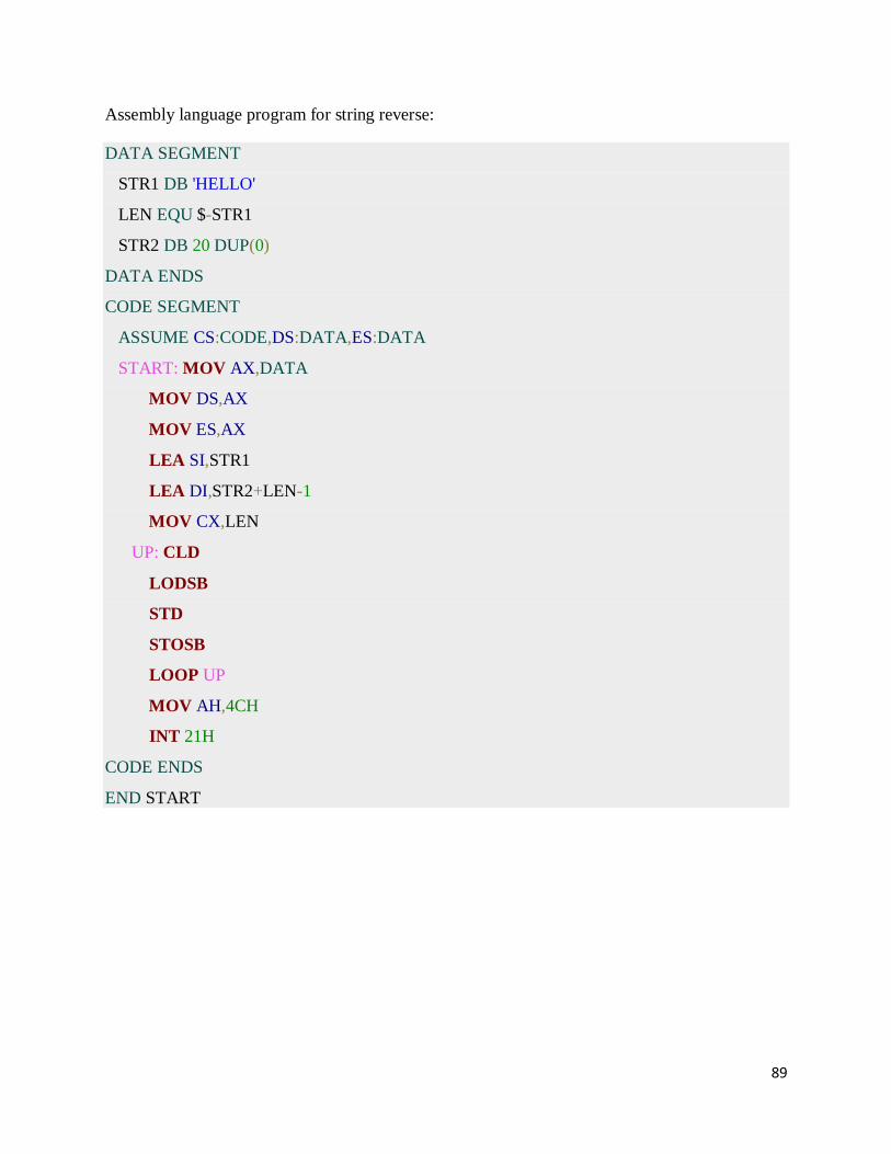
89
Assembly language program for string reverse:
DATA SEGMENT
STR1 DB 'HELLO'
LEN EQU $-STR1
STR2 DB 20 DUP(0)
DATA ENDS
CODE SEGMENT
ASSUME CS:CODE,DS:DATA,ES:DATA
START: MOV AX,DATA
MOV DS,AX
MOV ES,AX
LEA SI,STR1
LEA DI,STR2+LEN-1
MOV CX,LEN
UP: CLD
LODSB
STD
STOSB
LOOP UP
MOV AH,4CH
INT 21H
CODE ENDS
END START

90
6.3 PROCEDURES:
Assembly language program for printing HELLO WORLD using procedures:
ORG 100h
LEA SI, msg ; load address of msg to SI.
CALL print_me
RET ; return to operating system.
; ==========================================================
; this procedure prints a string, the string should be null
; terminated (have zero in the end),
; the string address should be in SI register:
print_me PROC
next_char:
CMP b.[SI], 0 ; check for zero to stop
JE stop ;
MOV AL, [SI] ; next get ASCII char.
MOV AH, 0Eh ; teletype function number.
INT 10h ; using interrupt to print a char in AL.
ADD SI, 1 ; advance index of string array.
JMP next_char ; go back, and type another char.
stop:
RET ; return to caller.
print_me ENDP
; ==========================================================
msg DB 'Hello World!', 0 ; null terminated string.
END

91
6.4 MACROS:
a. Write ALP macros:
i To read a character from the keyboard in the module (1) (in a different file).
ii To display a character in module(2) (from different file)
iii Use the above two modules to read a string of characters from the keyboard
terminated by the carriage return and print the string on the display in the next line.
.model small
.data
String db 30 dup (?)
.code
include c:\masm\read.mac
include c:\masm\write.mac
start: mov ax, @data
mov ds, ax
mov si, 00h
again: read
cmp al, 0dh
je down
mov string[si], al
inc si
jmp again
down: mov cx, si
mov si, 00h

92
write 0dh
write 0ah
back: write string[si]
inc si
loop back
int 3
end start
read.mac
read macro
mov ah, 01h
int 21h
endm
write.mac
write macro x
mov dl, x
mov ah, 02h
int 21h
endm

93
Conclusion:
This program reads a string message till enter key is pressed (user has to enter the string). As
soon as enter key pressed the read string will displayed on the screen.
Number Format, Conversions,ASCII operations, signed Numbers Arithmetic:
Assembly Language Program for 32 Bit addition:
DATA SEGMENT
NUM1 DW 0FFFFH,0FFFFH
NUM2 DW 1111H,1111H
SUM DW 4 DUP(0)
dATA ENDS
CODE SEGMENT
ASSUME CS:CODE,DS:DATA
START: MOV AX,DATA
MOV DS,AX
MOV AX,NUM1
ADD AX,NUM2
MOV SUM,AX
MOV AX,NUM1+2
ADC AX,NUM2+2
;Move LSB of NUM1 to AX
;Add LSB of NUM2 to AX
;Store the LSB in SUM
; Move MSB of NUM1 to AX
; Add MSB of NUM2 to AX
JNC DOWN ; Check for carry
MOV SUM+4,01H
DOWN: MOV SUM+2,AX
MOV AH,4CH

94
INT 21H
CODE ENDS
END START
INPUT: 0FFFFFFFFH, 011111111H
OUTPUT: 0111111110H
Assembly Language Program for 16 Bit Multiplication for signed numbers:
DATA SEGMENT
NUM DW -2,1
PROD DW 2 DUP(0)
DATA ENDS
CODE SEGMENT
ASSUME CS:CODE,DS:DATA
START: MOV AX,DATA
MOV DS,AX
LEA SI,NUM ; SI pointed to the Multiplicand
MOV AX,[SI] ; Multiplicand has to be in AX register
MOV BX,[SI+2] ; SI+2 pointed to the Multiplier and move it to BX
IMUL BX ; Perform the sign multiplication using sign
;Multiplication operator (IMUL)
MOV PROD,AX ; 32 bit product stored in DX-AX registers
MOV PROD+2,DX
MOV AH,4CH
INT 21H
CODE ENDS
END START

95
Assembly Language Program for Binary to BCD Conversion:
DATA SEGMENT
BIN DW 01A9H
BCD DB 2 DUP(0)
DATA ENDS
CODE SEGMENT
ASSUME CS:CODE,DS:DATA
START: MOV AX,DATA
MOV DS,AX
MOV AX,BIN
MOV CL,64H
DIV CL
MOV BCD+1,AL
MOV AL,AH
MOV AH,00H
MOV CL,0AH
DIV CL
MOV CL,04
ROR AL,CL
ADD AL,AH
MOV AH,4CH
INT 21H
CODE ENDS
END START
Assembly Language Program To Convert From Hex To Ascii or Display a Number As String:
; Program To Convert From Hex To Ascii or Display Number in 8086
Assembly Language
; Author : Murugan Andezuthu Dharmaratnam
; Modified : Oct 09 2012

96
org 100h
main proc near
mov ah,09h ; Display String
mov dx,offset message
int 21h
mov ax,55h ; AX Contains Hex 55H = 85 Decimal
mov si,offset strHextToAsc ; SI Offset Where Converted
to String is stored
call hexToAsc
mov ah,,09h ; Display String : Number Converted
mov dx,offset strHextToAsc
int 21h
mov ah,4ch ; Return To Dos
mov al,00
int 21h
endp
hexToAsc proc near ;AX input , si point result storage addres
mov cx,00h
mov bx,0ah
hexloop1:
mov dx,0
div bx
add dl,'0'
push dx
inc cx
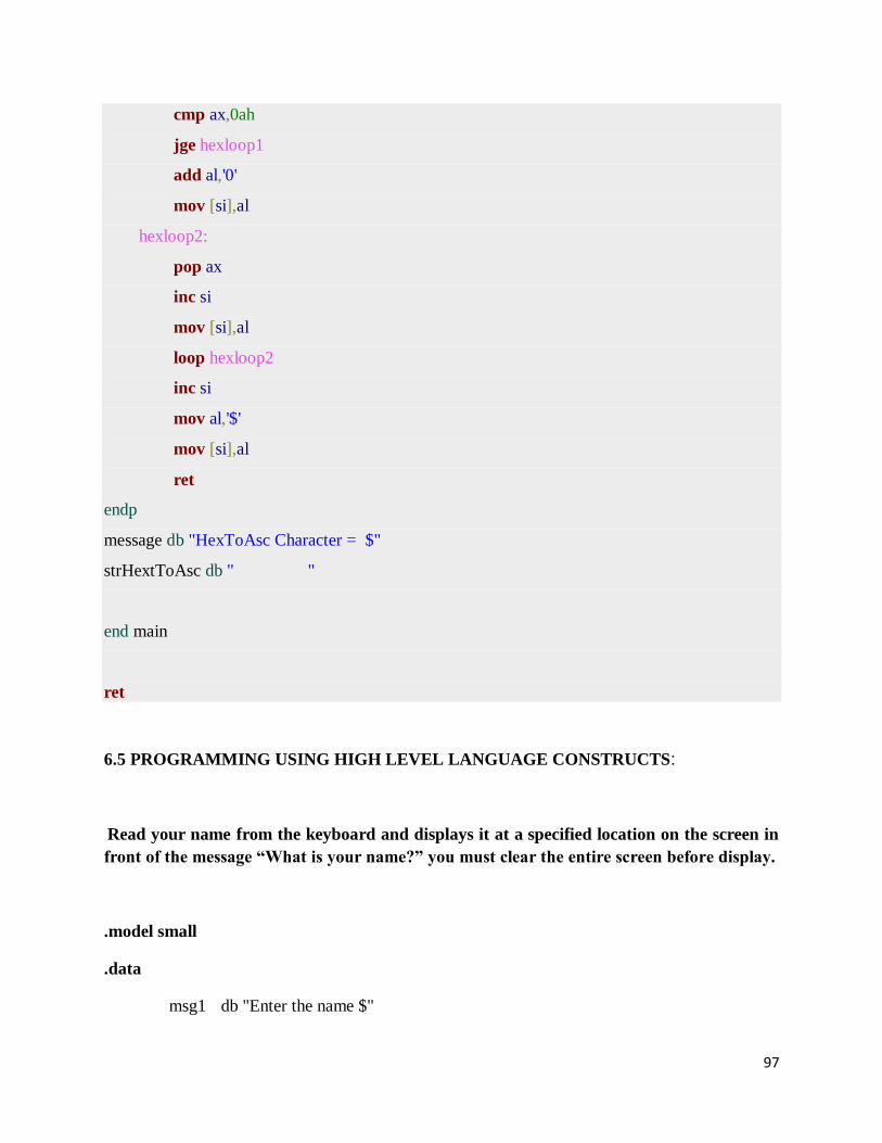
97
cmp ax,0ah
jge hexloop1
add al,'0'
mov [si],al
hexloop2:
pop ax
inc si
mov [si],al
loop hexloop2
inc si
mov al,'$'
mov [si],al
ret
endp
message db "HexToAsc Character = $"
strHextToAsc db " "
end main
ret
6.5 PROGRAMMING USING HIGH LEVEL LANGUAGE CONSTRUCTS:
Read your name from the keyboard and displays it at a specified location on the screen in
front of the message “What is your name?” you must clear the entire screen before display.
.model small
.data
msg1 db "Enter the name $"
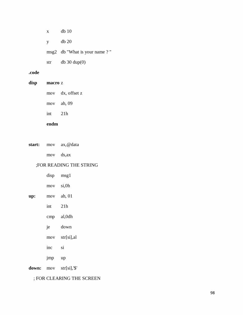
98
x db 10
y db 20
msg2 db "What is your name ? "
str db 30 dup(0)
.code
disp macro z
mov dx, offset z
mov ah, 09
int 21h
endm
start: mov ax,@data
mov ds,ax
;FOR READING THE STRING
disp msg1
mov si,0h
up: mov ah, 01
int 21h
cmp al,0dh
je down
mov str[si],al
inc si
jmp up
down: mov str[si],'$'
; FOR CLEARING THE SCREEN

99
mov cx, 29h*50h
mov dl, ' '
mov ah, 02
back: int 21h
loop back
mov dl, x
mov dh, y
mov bh, 00h
mov ah, 02
int 10h
disp msg2
mov ah,01
int 21h
int 3
end start
Conclusion:
This program will reads a string and displays the same string on the screen at the desired
position after clearing the screen.
Compute the factorial of a positive integer ‘n’ using recursive procedure.
.model small
.stack 100h
.data
n1 dw 3

100
nfact dw ?
.code
start: mov ax, @data
mov ds, ax
mov ax, 01
mov dx, 00
mov cx, n1
; CALL THE PROCEDURE FACTN
call factn
mov nfact,ax
mov nfact+2, dx
int 3
factn proc
cmp cx,00
je exit
cmp cx, 01
je exit
push cx
dec cx
call factn
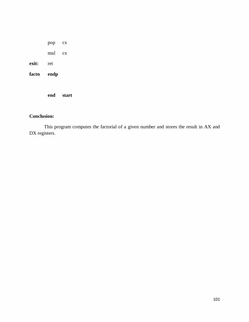
101
pop cx
mul cx
exit: ret
factn endp
end start
Conclusion:
This program computes the factorial of a given number and stores the result in AX and
DX registers.