department of computer science€¦ · · 2016-11-29laboratory manual prepared by: muhammad...
TRANSCRIPT

INSTITUTE OF SOUTHERN PUNJAB (ISP),
MULTAN
Page 1 of 43
Department Of Computer Science
Laboratory Manual
Prepared By: Muhammad Nouman Farooq
Lecturer and Course Coordinator
Course: Computer Communication and Networks (CS-205)

INSTITUTE OF SOUTHERN PUNJAB (ISP),
MULTAN
Page 2 of 43
Table of Contents
Lab 1- Introduction and Getting Started…………………………………….3-17
Lab 2- Network Simulation…………………………………………………18-36
2.1- Address Resolution Protocol (ARP)
2.2 – Adding Routers and Installing Modules
2.3 – Basic Router Configurations using Config Mode
2.4 - Creating a Copy of Existing Router
2.5 - Configuring the Wide Area Network (WAN) Link
2.6 - Configuring the Routing Protocol: Routing Information Protocol (RIP)
2.7 - Setting the default Gateway on the Personal Computers (PCs)
2.8 - Testing the Connectivity of the Build Network
2.9 – Saving the Packet Tracer File
Lab 3- Configuring DHCP & DNS & Web Server……………………..….37-44

INSTITUTE OF SOUTHERN PUNJAB (ISP),
MULTAN
Page 3 of 43
Lab 1- Introduction and Getting Started
What is Packet Tracer?
Packet Tracer is a protocol simulator developed by Dennis
Frezzo and his team at Cisco Systems. Packet Tracer (PT) is a powerful and
dynamic tool that displays the various protocols used in networking, in either Real
Time or Simulation mode. This includes layer 2 protocols such as Ethernet and
PPP, layer 3 protocols such as IP, ICMP, and ARP, and layer 4 protocols such as
TCP and UDP. Routing protocols can also be traced.
Purpose: The purpose of this lab is to become familiar with the Packet Tracer
interface. Learn how to use existing topologies and build your own.
Requisite Knowledge: This lab assumes some understanding of the Ethernet
protocol. At this point we have not discussed other protocols, but will use Packet
Tracer in later labs to discuss those as well.
Version: This lab is based on Cisco Packet Tracer 6.1 for Windows – Student
version.

INSTITUTE OF SOUTHERN PUNJAB (ISP),
MULTAN
Page 4 of 43
Introduction to the Packet Tracer Interface using a Hub and making some
Physical Topologies
Step 1: Start Packet Tracer and Entering Real-time Mode

INSTITUTE OF SOUTHERN PUNJAB (ISP),
MULTAN
Page 5 of 43
Step 2: Choosing Devices and Connections
We will begin building our network topology
by selecting devices and the media in which to connect them. Several types of
devices and network connections can be used. For this lab we will keep it simple
by using End Devices, Switches, Hubs, and Connections.
Single click on each group of devices and connections to display the various
choices

INSTITUTE OF SOUTHERN PUNJAB (ISP),
MULTAN
Page 6 of 43
Step 3: Building the Topology – Adding Hosts
Single click on the End Devices
Move the cursor into topology area. You will notice it turns into a plus “+” sign.
Single click in the topology area and it copies the device.
Add three more Hosts

INSTITUTE OF SOUTHERN PUNJAB (ISP),
MULTAN
Page 7 of 43
Step 4: Building the Topology – Connecting the Hosts to Hubs and Switches
Adding a Hub Select a hub, by clicking once on Hubs and once on a Generic hub
Perform the following steps to connect PC0 to Hub0:
1. Click once on PC0
2. Choose Fast Ethernet
3. Drag the cursor to Hub0

INSTITUTE OF SOUTHERN PUNJAB (ISP),
MULTAN
Page 8 of 43
4. Click once on Hub0 and choose Port 0
5. Notice the green link lights on both the PC0 Ethernet NIC and the Hub0 Port 0
showing that the link is active

INSTITUTE OF SOUTHERN PUNJAB (ISP),
MULTAN
Page 9 of 43

INSTITUTE OF SOUTHERN PUNJAB (ISP),
MULTAN
Page 10 of 43
Perform the following steps to connect PC2 to Switch0:
1. Click once on PC2
2. Choose FastEthernet
3. Drag the cursor to Switch0
4. Click once on Switch0 and choose FastEthernet0/1
5. Notice the green link lights on PC2 Ethernet NIC and amber light Switch0
FastEthernet0/1 port
The switch port is temporarily not forwarding frames, while it goes
through the stages for the Spanning Tree Protocol (STP) process. 6. After a about
30 seconds the amber light will change to green indicating that the port has entered
the forwarding stage. Frames can now forwarded out the switch port.

INSTITUTE OF SOUTHERN PUNJAB (ISP),
MULTAN
Page 11 of 43
Step 5: Configuring IP Addresses and Subnet Masks on the Hosts

INSTITUTE OF SOUTHERN PUNJAB (ISP),
MULTAN
Page 12 of 43
Also, notice this is where you can change the Bandwidth (speed) and Duplex of the
Ethernet NIC (Network Interface Card). The default is Auto (auto negotiation),
which means the NIC will negotiate with the hub or switch. The bandwidth and/or
duplex can be manually set by removing the check from the Auto box and
choosing the specific option.
Bandwidth – Auto
If the host is connected to a hub or switch port which can do 100
Mbps, then the Ethernet NIC on the host will choose 100 Mbps (Fast Ethernet).
Otherwise, if the hub or switch port can only do 10 Mbps, then the Ethernet NIC
on the host will choose 10 Mbps (Ethernet)

INSTITUTE OF SOUTHERN PUNJAB (ISP),
MULTAN
Page 13 of 43
Duplex - Auto
Hub:
If the host is connected to a hub, then the Ethernet NIC on the host will
choose Half Duplex.
Switch:
If the host is connected to a switch, and the switch port is configured as Full
Duplex (or Auto negotiation), then the Ethernet NIC on the host will choose Full
Duplex. If the switch port is configured as Half Duplex, then the Ethernet NIC on
the host will choose Half Duplex. (Full Duplex is a much more efficient option.)
The information is automatically saved when entered.
Repeat these steps for the other hosts. Use the information below for IP Addresses
and Subnet Masks.

INSTITUTE OF SOUTHERN PUNJAB (ISP),
MULTAN
Page 14 of 43
Verify the Information:
To verify the information that you entered, move the Select tool (arrow) over
each host.
Deleting a Device or Link:
To delete a device or link, choose the Delete tool and click on the item you
wish to delete.
Step 6: Connecting Hub0 to Switch0
To connect like-devices, like a Hub and a Switch, we will use a Cross-over cable.
Click once the Cross-over Cable from the Connections options.

INSTITUTE OF SOUTHERN PUNJAB (ISP),
MULTAN
Page 15 of 43

INSTITUTE OF SOUTHERN PUNJAB (ISP),
MULTAN
Page 16 of 43

INSTITUTE OF SOUTHERN PUNJAB (ISP),
MULTAN
Page 17 of 43
Lab Task:
1. Design the following Topologies for LAN using hub and switches and 15
PC’s connected together
a) Buss
b) Star
c) Tree
d) Hybrid Topologies
Home Task:
1. Briefly describe the Connections section of Packet Tracer.
END OF LAB 1

INSTITUTE OF SOUTHERN PUNJAB (ISP),
MULTAN
Page 18 of 43
Lab 2- Network Simulation
2. Network Simulation:
In this part, we are going to use the simulator to
simulate traffic between hosts. For this scenario, delete the switch and host
PC3, then connect host PC2 to the hub from lab 1.
Observe the flow of data from PC0 to PC1 by Creating Network Traffic.
a) Switch to Simulation Mode by selecting the tab that is partially hidden behind
the Real Time tab in the bottom right-hand corner. The tab has the icon of a
stopwatch on it.
NOTE: When Simulation Mode is chosen, a Simulation Panel will appear on the
right side of the screen. This panel can be moved by moving the cursor at the top
of the panel until it changes and then double-clicking on it. The panel can be
restored to the original location by double-clicking on the Title bar. If the panel is
closed, click on the Event List button.
INSTITUTE OF SOUTHERN PUNJAB (ISP),
MULTAN
Page 19 of 43
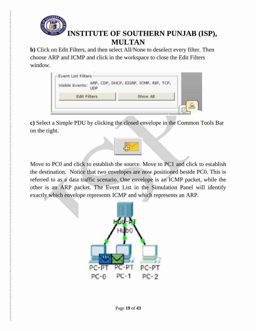
b) Click on Edit Filters, and then select All/None to deselect every filter. Then
choose ARP and ICMP and click in the workspace to close the Edit Filters
window.
c) Select a Simple PDU by clicking the closed envelope in the Common Tools Bar
on the right.
Move to PC0 and click to establish the source. Move to PC1 and click to establish
the destination. Notice that two envelopes are now positioned beside PC0. This is
referred to as a data traffic scenario. One envelope is an ICMP packet, while the
other is an ARP packet. The Event List in the Simulation Panel will identify
exactly which envelope represents ICMP and which represents an ARP.

INSTITUTE OF SOUTHERN PUNJAB (ISP),
MULTAN
Page 20 of 43
A scenario may be deleted by clicking on the Delete button in the Scenario panel.
Multiple scenarios can be created by clicking on the new button in the Scenario
panel. The scenarios can then be toggled between without deleting.
d) Select Auto Capture / Play from the Simulation Panel Play Controls. Below the
Auto Capture / Play button is a horizontal bar, with a vertical button that controls
the speed of the simulation. Dragging the button to the right will speed up the
simulation, while dragging is to the left will slow down the simulation.
e) Choose the Reset Simulation button in the Simulation window.
Notice that the ARP envelope is no longer present. This has reset the simulation
but has not cleared any configuration changes or MAC / ARP table entries.

INSTITUTE OF SOUTHERN PUNJAB (ISP),
MULTAN
Page 21 of 43
f) Choose the Capture / Forward button.
Notice that the ICMP envelope moved forward one device and stopped. The
Capture / Forward button will allow you to move the simulation one step at a time.
h) Choose the Power Cycle Devices button on the bottom left, above the device
icons.
Choose: Yes
Notice that both the ICMP and ARP envelopes are now present. The Power Cycle
Devices will clear any configuration changes not saved and clear the MAC / ARP
tables.

INSTITUTE OF SOUTHERN PUNJAB (ISP),
MULTAN
Page 22 of 43
2.1- Address Resolution Protocol (ARP)
a) Choose the Auto Capture / Play button and allow the simulation to run
completely.
b) Click on PC-0 and select the Desktop tab.
c) Select the Command Prompt and type the command:
arp –a
d) Notice that the MAC address for PC2 is in the ARP table (to view the MAC
address of PC2, click on PC2 and select the Config tab).

INSTITUTE OF SOUTHERN PUNJAB (ISP),
MULTAN
Page 23 of 43
e) To examine the ARP tables for PC1 and PC2 in another way, click on the
Inspect Tool.
Then click on PC1 and the ARP table will appear in a new window.
Note that PC2 does not have an entry in the ARP table yet.
Close the ARP Table window.
f) Click on PC2 to view the ARP table. Then close the ARP Table window.
NOTE: To deactivate the Inspect Tool, click on the Select Tool
INSTITUTE OF SOUTHERN PUNJAB (ISP),
MULTAN
Page 24 of 43
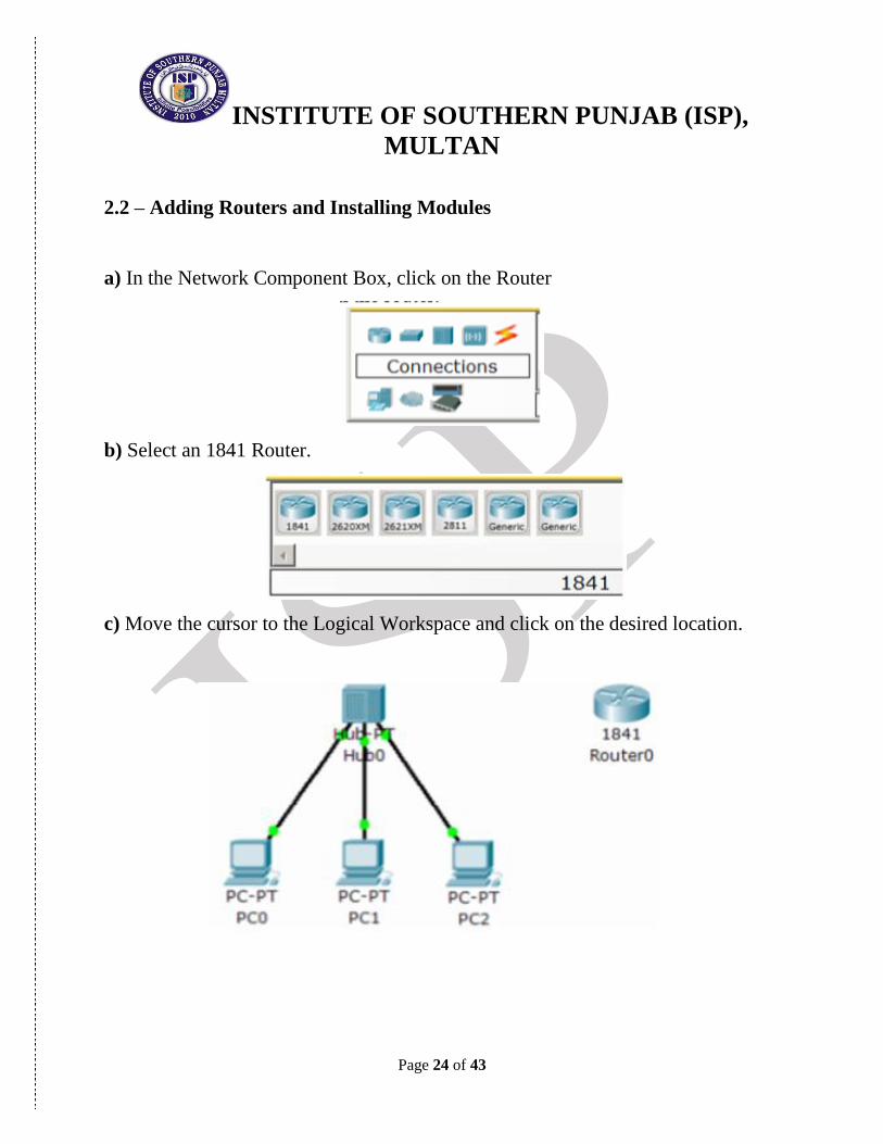
2.2 – Adding Routers and Installing Modules
a) In the Network Component Box, click on the Router
b) Select an 1841 Router.
c) Move the cursor to the Logical Workspace and click on the desired location.

INSTITUTE OF SOUTHERN PUNJAB (ISP),
MULTAN
Page 25 of 43
NOTE: If multiple instances of the same device are needed press and hold the Ctrl
button, click on the desired device, and then release the Ctrl button. A copy of the
device will be created and can now be move to the desired location.
d) Click on the router to bring up the Configuration Window. This window has
three modes: Physical, Config, and CLI (Physical is the default mode).
The Physical mode is used to add modules to a device, such as a WAN Interface
Card (WIC). The Config mode is used for basic configuration. Commands are
entered in a simple GUI format, with actual equivalent IOS commands shown in
the lower part of the window.
The CLI mode allows for advanced configuration of the device. This mode
requires the user to enter the actual IOS commands just as they would on a live
device.
INSTITUTE OF SOUTHERN PUNJAB (ISP),
MULTAN
Page 26 of 43
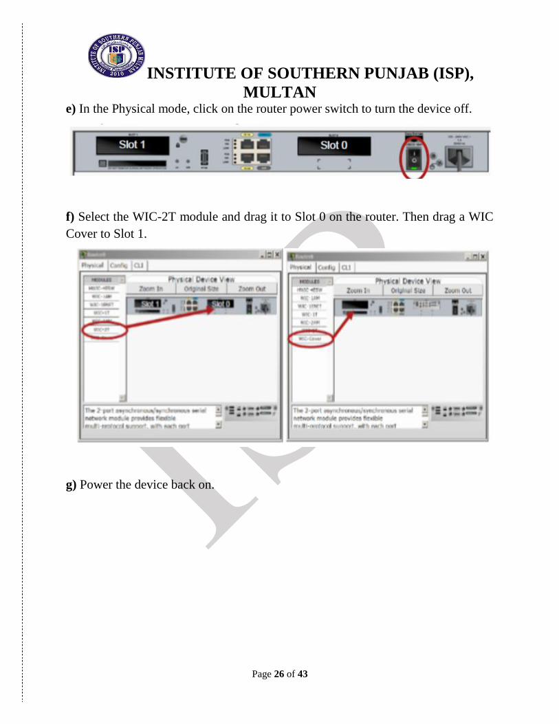
e) In the Physical mode, click on the router power switch to turn the device off.
f) Select the WIC-2T module and drag it to Slot 0 on the router. Then drag a WIC
Cover to Slot 1.
g) Power the device back on.

INSTITUTE OF SOUTHERN PUNJAB (ISP),
MULTAN
Page 27 of 43
h) Click on the Network Component Box and select Connections. Then select a
Copper Straight-through connection to connect the router to the hub.
NOTE: The Smart Connection can be used to automatically select the
appropriate cable type. However, the user will have no choice as to which interface
the connection is assigned to; it will take the first available appropriate interface.
Click on the hub and choose Port 3. Then click on the router and choose interface
FastEthernet 0/0.

INSTITUTE OF SOUTHERN PUNJAB (ISP),
MULTAN
Page 28 of 43
2.3 – Basic Router Configurations using Config Mode
a) Click on the Config mode tab of Router0 to begin configuring the device
b) After the device has finished booting, change the display name of the router to
CISCO_1. Changing the display name does not affect the configuration.
NOTE: If the device hangs up in the booting process, save the activity. Then close
the application and reopen the file
c) Click in the Hostname field and type CISCO_1, then press the TAB key. Note
the equivalent IOS command is entered in the lower portion of the window.
d) Click on interface FastEthernet 0/0 and assign the IP address 192.168.1.1, then
press the TAB key. Enter the subnet mask 255.255.255.0.
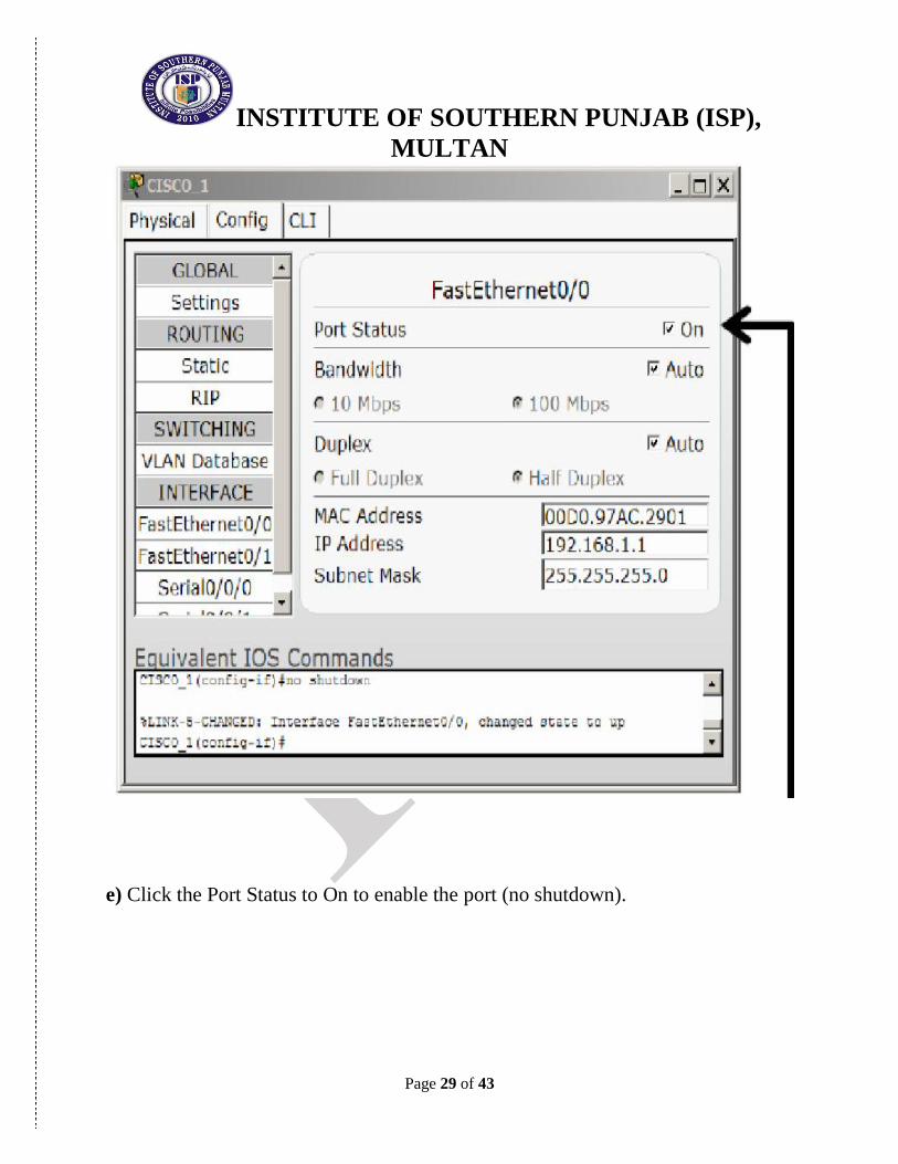
INSTITUTE OF SOUTHERN PUNJAB (ISP),
MULTAN
Page 29 of 43
e) Click the Port Status to On to enable the port (no shutdown).
INSTITUTE OF SOUTHERN PUNJAB (ISP),
MULTAN
Page 30 of 43
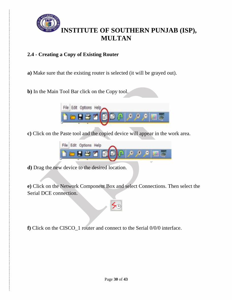
2.4 - Creating a Copy of Existing Router
a) Make sure that the existing router is selected (it will be grayed out).
b) In the Main Tool Bar click on the Copy tool.
c) Click on the Paste tool and the copied device will appear in the work area.
d) Drag the new device to the desired location.
e) Click on the Network Component Box and select Connections. Then select the
Serial DCE connection.
f) Click on the CISCO_1 router and connect to the Serial 0/0/0 interface.

INSTITUTE OF SOUTHERN PUNJAB (ISP),
MULTAN
Page 31 of 43
g) Click on the new router (copy CISCO_1) and connect to the Serial 0/0/0
interface.

INSTITUTE OF SOUTHERN PUNJAB (ISP),
MULTAN
Page 32 of 43
2.5 - Configuring the Wide Area Network (WAN) Link
a) Click on the CISCO_1 router and select the Config mode
b) Select interface Serial 0/0/0
c) Configure the interface Serial 0/0/0 with the IP address 192.168.2.1, then press
the TAB key and enter the subnet mask 255.255.255.0 on the interface.
d) Set the clock rate to 56000
e) Click the Port Status to On to enable the port (no shutdown).
f) Click on the new router and select the Config mode.
g) Change the Display Name and Hostname to CISCO_2.
h) Configure the interface Serial 0/0/0 with the IP address 192.168.2.2, then press
the TAB key and enter the subnet mask 255.255.255.0 on the interface.
i) Click the Port Status to On to enable the port (no shutdown).
NOTE: The link lights on the serial link should change from red to green to
indicate the link is active.

INSTITUTE OF SOUTHERN PUNJAB (ISP),
MULTAN
Page 33 of 43
2.6 - Configuring the Routing Protocol: Routing Information Protocol (RIP)
a) Click on the CISCO_1 router and select the Config tab. Then click on RIP and
add the network address 192.168.1.0 and 192.168.2.0.
b) Click on the CISCO_2 router and select the Config tab. Then click on RIP and
add the network address 192.168.2.0.
c) Go to each PC and set the Default Gateway to 192.168.1.1

INSTITUTE OF SOUTHERN PUNJAB (ISP),
MULTAN
Page 34 of 43
2.7 - Setting the default Gateway on the Personal Computers (PCs)
a) Click on PC0 and select the Config tab. Enter the default gateway address
192.168.1.1.
b) Click on PC1 and select the Config tab. Enter the default gateway address
192.168.1.1.
c) Click on PC2 and select the Config tab. Enter the default gateway address
192.168.1.1.

INSTITUTE OF SOUTHERN PUNJAB (ISP),
MULTAN
Page 35 of 43
2.8 Testing the Connectivity of the Build Network
a) Click on the Simulation mode.
b) Select a Simple PDU and click on PC-A as the source, then click on
Cisco_2 as the destination. The ping should be successful.
2.9 – Saving the Packet Tracer File
a) Save the Packet Tracer file with the name:
Your Name-Class-Semester-Section-lab2
END OF LAB 2

INSTITUTE OF SOUTHERN PUNJAB (ISP),
MULTAN
Page 36 of 43
Lab 3- Configuring DHCP & DNS & Web Server
1. Start Packet Tracer using Realtime mode.
Options -> Preferences o Enable “Show Link Lights” o Disable “Hide Device Label”
2. Configuring the DHCP Server
Add a server.
Global Settings:
Change the Display Name to “DHCP Server”
Set the Gateway to 172.16.0.1 FastEthernet:
Set the IP address to 172.16.0.10
Set the Subnet Mask to 255.255.0.0 HTTP:
Set HTTP Service and HTTPS Service to Off DHCP:
Set the Default Gateway to 172.16.0.1
Set the DNS Server to 172.16.0.11
Set the Start IP Address to 172.16.0.100 DNS:
Set the Service to Off
INSTITUTE OF SOUTHERN PUNJAB (ISP),
MULTAN
Page 37 of 43
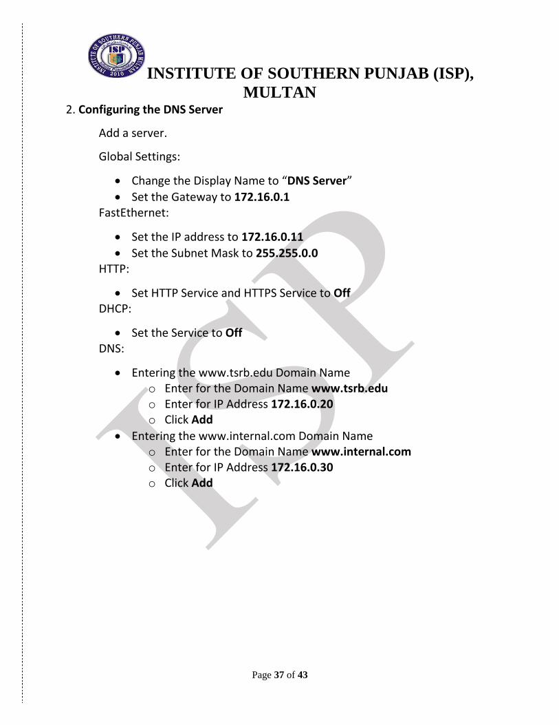
2. Configuring the DNS Server
Add a server.
Global Settings:
Change the Display Name to “DNS Server”
Set the Gateway to 172.16.0.1 FastEthernet:
Set the IP address to 172.16.0.11
Set the Subnet Mask to 255.255.0.0 HTTP:
Set HTTP Service and HTTPS Service to Off DHCP:
Set the Service to Off DNS:
Entering the www.tsrb.edu Domain Name o Enter for the Domain Name www.tsrb.edu o Enter for IP Address 172.16.0.20 o Click Add
Entering the www.internal.com Domain Name o Enter for the Domain Name www.internal.com o Enter for IP Address 172.16.0.30 o Click Add

INSTITUTE OF SOUTHERN PUNJAB (ISP),
MULTAN
Page 38 of 43
3. Configuring the www.tsrb.edu Web Server
Add a server.
Global Settings:
Change the Display Name to “Web Server: www.tsrb.edu”
Set the Gateway to 172.16.0.1 FastEthernet:
Set the IP address to 172.16.0.20
Set the Subnet Mask to 255.255.0.0 DHCP:
Set the Service to Off DNS:
Set the Service to Off HTTP
Change the sentence, “<hr>Welcome to Packet Tracer 5.0, the best thing since..... Packet Tracer 4.0.” to “<hr> Welcome to Tsrb's public web page!” You may add other information as well.

INSTITUTE OF SOUTHERN PUNJAB (ISP),
MULTAN
Page 39 of 43
4. Configuring the www.internal.com Web Server
Add a server.
Global Settings:
Change the Display Name to “Web Server: www.internal.com”
Set the Gateway to 172.16.0.1 FastEthernet:
Set the IP address to 172.16.0.30
Set the Subnet Mask to 255.255.0.0 DHCP:
Set the Service to Off DNS:
Set the Service to Off

INSTITUTE OF SOUTHERN PUNJAB (ISP),
MULTAN
Page 40 of 43
HTTP
Change the sentence, “<hr>Welcome to Packet Tracer 5.0, the best thing since..... Packet Tracer 4.0.” to “<hr> This is the corporate internal network!” You may add other information as well.
5. Configure Two Client Computers using DHCP
Add two client computers.
Global Settings:
Change the Display Names to “Dynamic 1” and to “Dynamic 2” respectively
Set the Gateway/DNS to DHCP FastEthernet:
Set the IP Configuration to DHCP
6. Configure One Client Computers using Static IP Addressing
Add two client computers.
Global Settings:
Change the Display Name to “Static”
Set the Gateway/DNS to Static Set Gateway to 172.16.0.1 Set the DNS Server to 172.16.0.11
FastEthernet:
Be sure the configuration is set to Static
Set the IP address to 172.16.0.90
Set the Subnet Mask to 255.255.0.0
INSTITUTE OF SOUTHERN PUNJAB (ISP),
MULTAN
Page 41 of 43
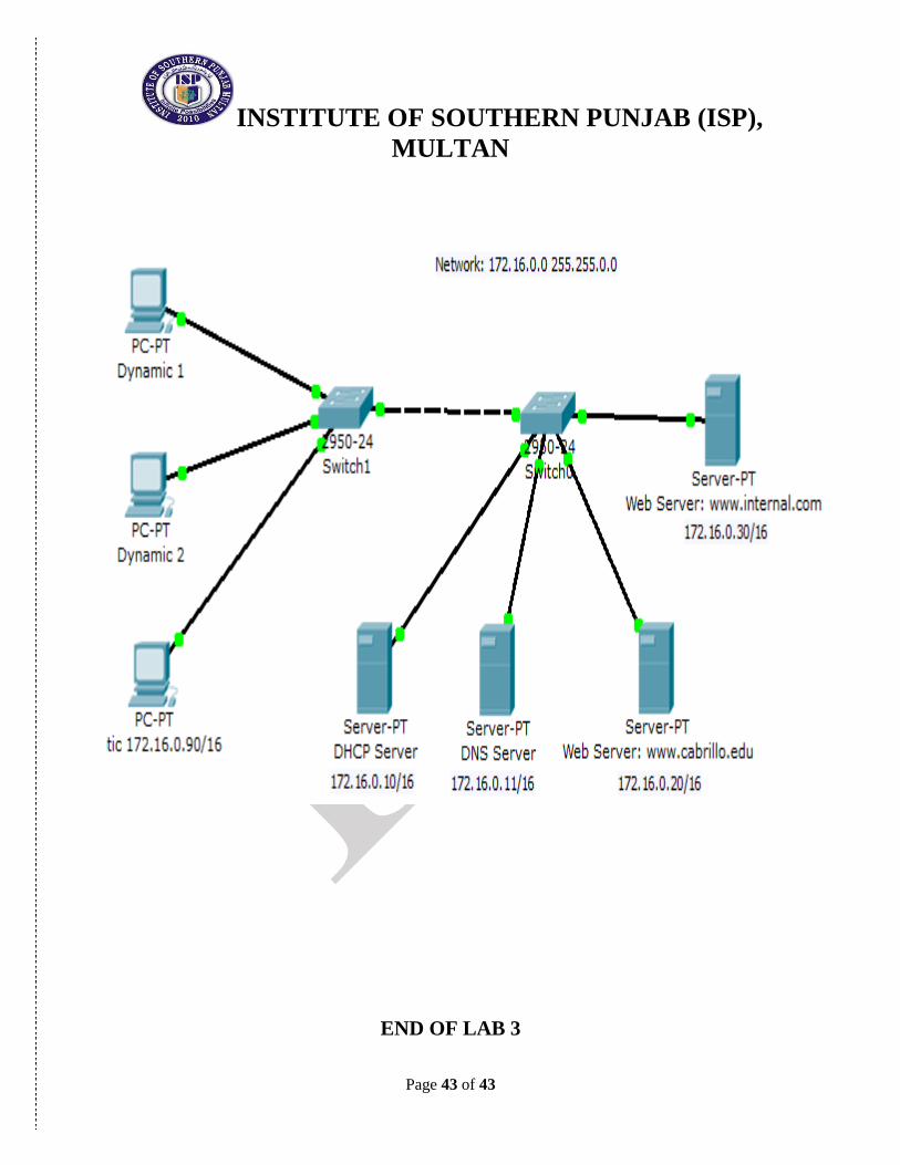
7. Adding switches
Add two switches.
Connect the servers to one switch using a straight-through cable.
Connect the client computers to the other switch using a straight-through cable.
Interconnect the two switches using a crossover cable.
8. Verify connectivity
Ping (ICMP) o From a client computer use the Desktop Command prompt to ping
the other client computers and the servers. o Example: From the Dynamic 1 client, C> ping 172.16.0.20 o The first one or two pings may fail, but you should receive a reply on
the later pings. This is due to the ping timing out while the ARP process takes place (later).
Web Browser (HTTP) o On the client computers use the Desktop Web Browser, enter the
URLs of the Web Servers www.tsrb.edu and www.internal.com. o You should see the web pages that you created on these servers.

INSTITUTE OF SOUTHERN PUNJAB (ISP),
MULTAN
Page 42 of 43
9. Using Simulation Mode
Click on Simulation.
Note: To reset a simulation, click on “Reset Simulation”
Click on Edit Filters
Choose Show All/None so that all the boxes (protocols) are unchecked.
Select (check) the following protocols: DHCP, ICMP, HTTP, DNS.
Web Browser (HTTP)
On the client computers use the Desktop Web Browser, enter the URLs of the Web Servers www.tsrb.edu or www.internal.com.
Click on Auto Capture/Play (automatically forwards the packets) or Capture Forward (must keep clicking to advance the packets)
DHCP
Reset the simulation by clicking on “Reset Simulation”
To view DHCP, on one of the “Dynamic “client computers using DHCP go to the Desktop Command prompt.
To have the client computer ask for new IP address and other information from the DHCP server, enter the command:
C> ipconfig /renew
INSTITUTE OF SOUTHERN PUNJAB (ISP),
MULTAN
Page 43 of 43
END OF LAB 3