department of computer science institute for system ... · department of computer science institute...
TRANSCRIPT
Mobile Communication andMobile Computing
Prof. Dr. Alexander Schillhttp://www.rn.inf.tu-dresden.de
Department of Computer Science Institute for System Architecture, Chair for Computer Networks
Structure of the Lecture
Part I: Mobile Communication- Introduction and Principles- GSM and Extensions- UMTS- LTE and beyond- WLAN- Satellite and Broadcast Systems
Part II: Mobile Computing- Mobile Internet Protocols- Web-based Mobile Applications- Mobile Platforms and Middleware- Context Awareness and Adaptation
Reference:- Jochen Schiller: Mobile Communications, Addison-Wesley
2

Introduction and Principles
3

Application Example: Civil Engineering, Field Service
4
Building site
Architect
Enterprise A(main office)
Enterprise B
Construction supervisor
GigabitEthernet
UMTS, LTE GSM, UMTS
Selected drafts,Videoconferences
Material data,status data,dates
Large archives,Videoconferences
Drafts,urgent modification
Enterprise A(branch office)
Gigabit Ethernet Fast Ethernet
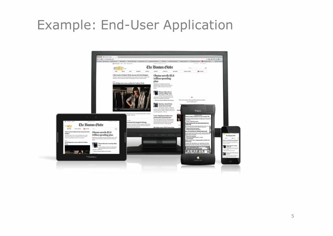
Example: End-User Application
5

Mobile Multimedia
6
Product Data ClientLAN-AccessMaintenance
technician
Very different performances and costs: radio networks versus fixed networks
Software-controlled, automatic adaptation to concrete system environmentsExample: Access to picture data / compressed
picture data / graphics / text
Mobile Access
Local Resources,Test Protocols
Main officeCaching
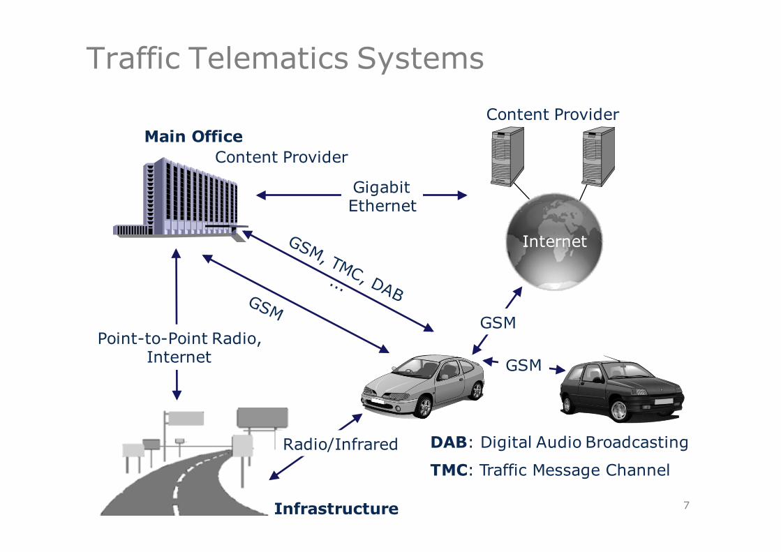
Traffic Telematics Systems
7
Internet
Content ProviderMain Office
Infrastructure
GSM
Radio/Infrared
GigabitEthernet
Point-to-Point Radio,Internet
Content Provider
DAB: Digital Audio Broadcasting
TMC: Traffic Message Channel

Mobile Communication: Development
8
200019951990
Mobile Phone Networks
Packet Networks
CircuitSwitchedNetworks
Satellite Networks
Local Networks
2005
D (GSM900)C
Modacom
MobitexTetra
Inmarsat
IR-LAN
3G/UMTS
IEEE 802.11Bluetooth
Radio-LAN
Iridium/Globalstar
E (GSM1800)
HSCSD
GPRS
Cordless Telephony
CT DECT
2010
5G(beyondLTE)
EDGE
4G/LTEadvanced
2015 2020
802.11n, acWiMAX

Used Acronyms
9
C: Analog “C” Network (1st Generation)CT: Cordless TelephoneDECT: Digital Enhanced Cordless TelecommunicationsGSM: Global System for Mobile Communications (2nd Generation)GPRS: General Packet Radio ServiceHSCSD:High Speed Downlink Packet Access (advanced)
High Speed Uplink Packet Access (advanced)High Speed Circuit Switched Data
EDGE: Enhanced Data Rates for GSM EvolutionLTE: Long Term EvolutionTETRA: Terrestrial Trunked Radio (Multicast Communication System)UMTS: Universal Mobile Telecommunications System (3rd Generation)4G: 4th Generation NetworksWiMAX Worldwide Interoperability for Microwave Access
C:CT:
DECT: GSM:
GPRS:HSDPA+:HSUPA+:
HSCSD:EDGE:
LTE:TETRA:UMTS:
4G: WiMAX:

Correspondent data rates
101995 2000 2005 2010
10Mbit/s UMTS(pico cell)
10kbit/s GSM
HSCSD/GPRS
EDGE
100kbit/s
1 Mbit/s
UMTS(macro cell)
Satellites
DECT
100 Mbit/s
300Mbit/s
2015
LTE (uplink) / HSDPA+
LTE (downlink)
WLAN
50Mbit/s
200 Mbit/s
HSUPA+
2020
1Gbit/s
5G
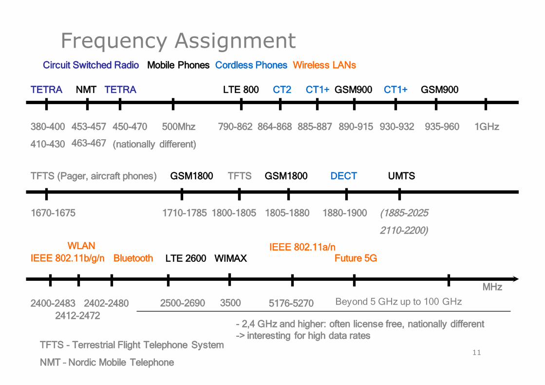
Frequency Assignment
11
TETRA
380-400
410-430
NMT
453-457
463-467
CT2
864-868
CT1+
885-887 890-915
GSM900 CT1+
930-932
GSM900
935-960
TFTS (Pager, aircraft phones) GSM1800
1670-1675 1710-1785 1800-1805
TFTS
1805-1880
GSM1800 DECT
1880-1900 (1885-2025
2110-2200)
TETRA
450-470
(nationally different)
UMTS
IEEE 802.11b/g/n
2400-2483 5176-5270
MHz
Bluetooth
2402-2480
Future 5G
Beyond 5 GHz up to 100 GHz
WLAN
2412-2472
Circuit Switched Radio Mobile Phones Cordless Phones Wireless LANs
- 2,4 GHz and higher: often license free, nationally different-> interesting for high data rates
1GHz500Mhz
TFTS - Terrestrial Flight Telephone System
NMT – Nordic Mobile Telephone
IEEE 802.11a/n
790-862
LTE 800
2500-2690
LTE 2600 WIMAX
3500

Principles of Mobile Communication
12
Based on electro-magnetic radio transmission
radio transmission
terrestrial orbital (satellite)
point-to-point Broadcast radio equatorial orbit
non-equatorialorbit
cellular non-cellular
Principles:– Propagation and reception of electro-magnetic waves– Modulation and multiplex methods; focusing on cellular networks
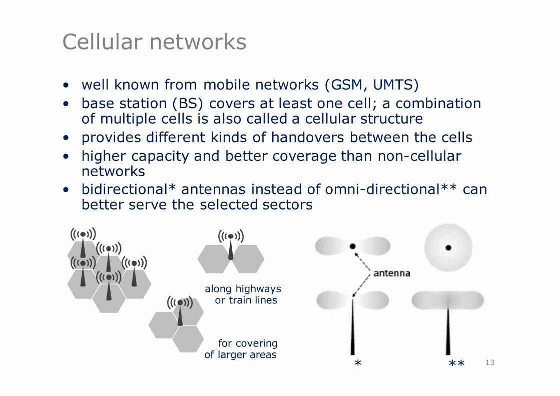
Cellular networks
• well known from mobile networks (GSM, UMTS)• base station (BS) covers at least one cell; a combination
of multiple cells is also called a cellular structure • provides different kinds of handovers between the cells• higher capacity and better coverage than non-cellular
networks• bidirectional* antennas instead of omni-directional** can
better serve the selected sectors
13
along highwaysor train lines
for coveringof larger areas
* **
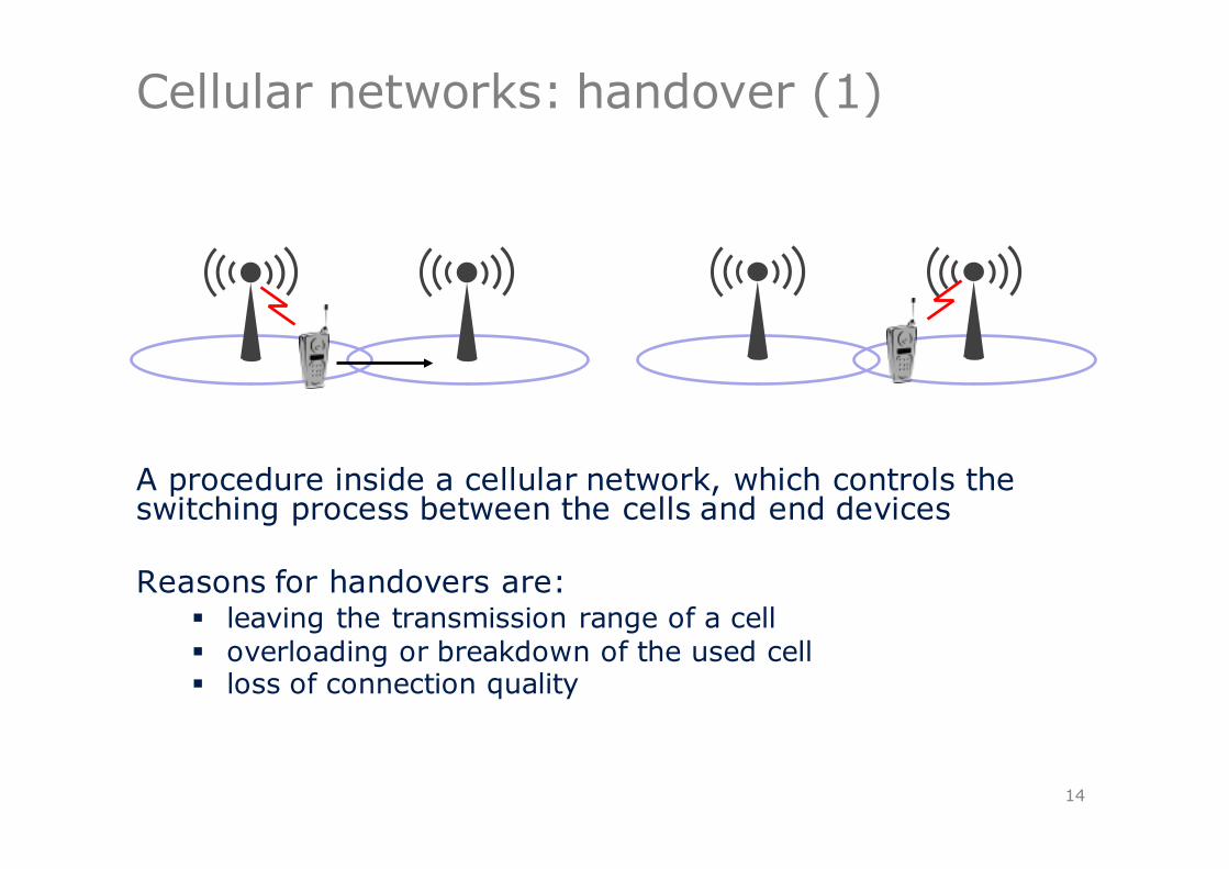
A procedure inside a cellular network, which controls the switching process between the cells and end devices
Reasons for handovers are:§ leaving the transmission range of a cell§ overloading or breakdown of the used cell § loss of connection quality
Cellular networks: handover (1)
14
Cellular networks: handover (2)
Handover classes§ Intra-cell: switch-over inside the cell onto other
frequency or other timeslot§ Inter-cell: switch-over to a neighboring cell§ Inter-system: switch-over between different
technologies (e.g. UMTS and LTE); roaming
Handover types§ Hard handover: active connection gets disconnected
before the connection to a new cell is established§ Soft handover: active connection gets disconnected
after the connection to a new cell is established
15

Structure of a cellular network
• Major problems:§ limited frequency
resources§ interference
• Therefore: reuse of frequency channels in remote cells
• Recommended reuse distance D:
where:N is the number of different cell types, andR is the cell radius
16
RND ⋅= 3
1
1
1
1
2
23
3
4
4
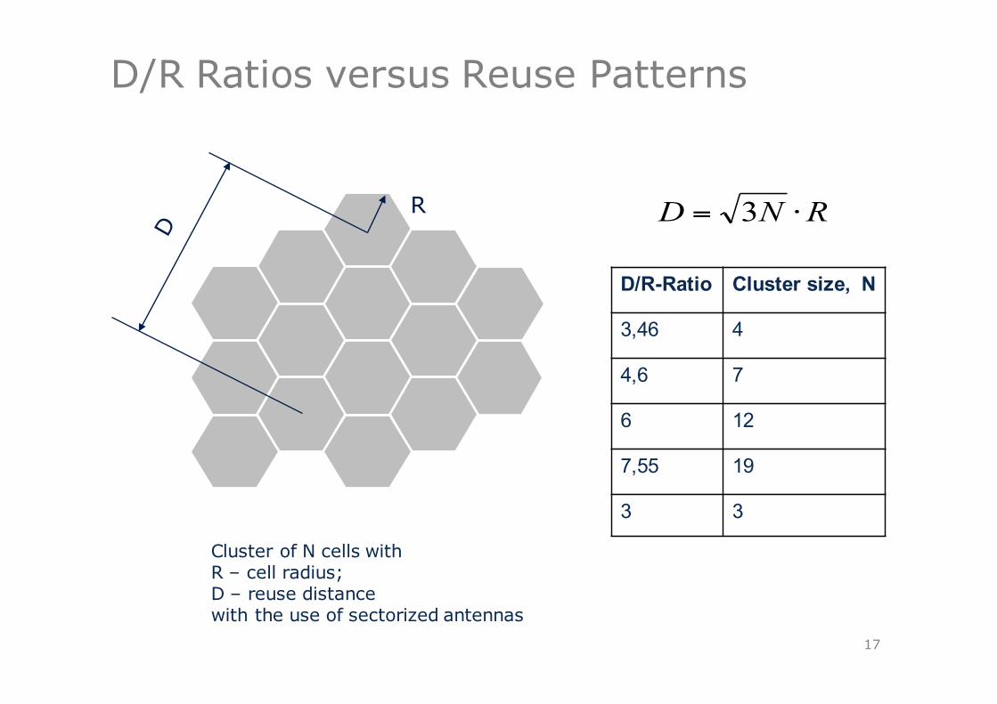
D/R Ratios versus Reuse Patterns
17
R
D/R-Ratio Cluster size, N
3,46 4
4,6 7
6 12
7,55 19
3 3
RND ⋅= 3
Cluster of N cells withR – cell radius; D – reuse distancewith the use of sectorized antennas
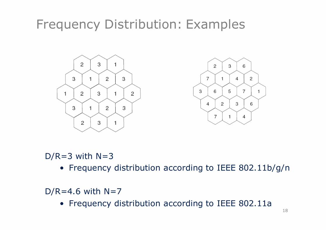
Frequency Distribution: Examples
18
D/R=3 with N=3 • Frequency distribution according to IEEE 802.11b/g/n
D/R=4.6 with N=7• Frequency distribution according to IEEE 802.11a

Multiplex Methods: Principles
Multiplex§ Concurrent usage of the medium without interference§ 4 multiplex methods:
− Space− Time− Frequency− Code
Medium Access§ controls user access to medium§ implemented by combining and exploiting multiplex
methods
19

SDMA (Space Division Multiple Access)
Communication channel relates to definite regional area or physical infrastructure
Space Multiplex for instance in the Analog Phone Systems (for each participant one line), for Broadcasting Stations, and in Cellular Networks
Problem: secure distance (interferences) between transmitting stations is required (using one frequency), and by pure Space Multiplex each communication channel would require an own transmitting station
Therefore space Multiplex is only reasonable in combination with other multiplex methods
20

SDMA: Example
21
k1 k2
s
s – secure distance
k3 k4 k5 k6
SDMA selects cell
f1

FDMA (Frequency Division Multiple Access)
• frequencies are permanently assigned to transmission channels (known from broadcast radio)
22
k1 k2 k3 k4 k5 k6
f1f2f3
f4f5f6
s – secure distance
s
FDMA selectsfrequency
t
f
k1
k2
k3
k4
k5
k6
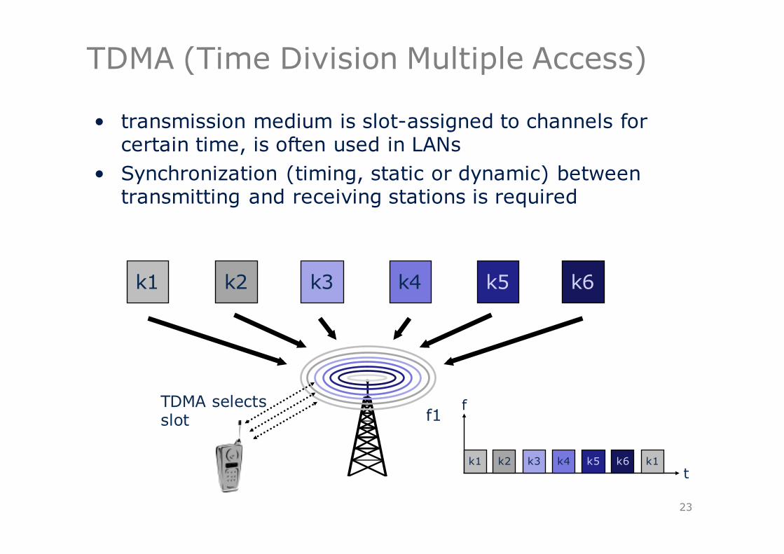
TDMA (Time Division Multiple Access)
• transmission medium is slot-assigned to channels for certain time, is often used in LANs
• Synchronization (timing, static or dynamic) between transmitting and receiving stations is required
23
k1 k2 k3 k4 k5 k6
f1
t
f
k1 k2 k3 k4 k5 k6 k1
TDMA selectsslot
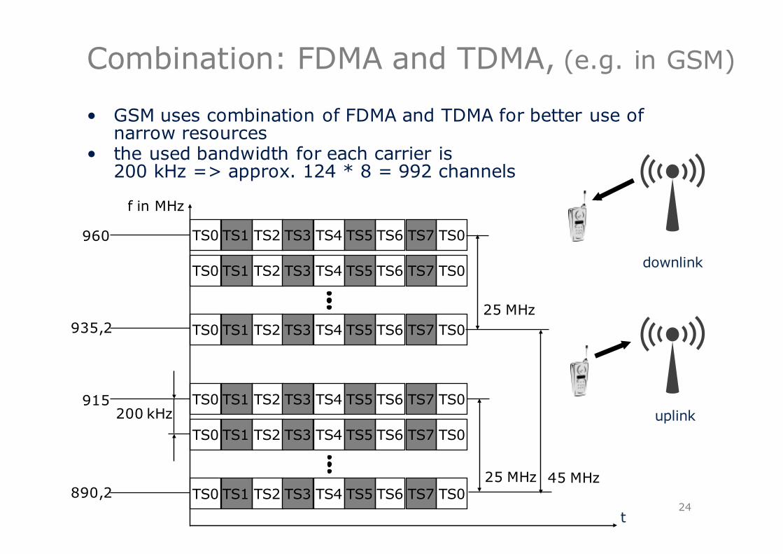
Combination: FDMA and TDMA, (e.g. in GSM)
• GSM uses combination of FDMA and TDMA for better use of narrow resources
• the used bandwidth for each carrier is 200 kHz => approx. 124 * 8 = 992 channels
24t
f in MHz
TS0 TS1 TS2 TS3 TS4 TS5 TS6 TS7 TS0
TS0 TS1 TS2 TS3 TS4 TS5 TS6 TS7 TS0
TS0 TS1 TS2 TS3 TS4 TS5 TS6 TS7 TS0
TS0 TS1 TS2 TS3 TS4 TS5 TS6 TS7 TS0
TS0 TS1 TS2 TS3 TS4 TS5 TS6 TS7 TS0
TS0 TS1 TS2 TS3 TS4 TS5 TS6 TS7 TS0
890,2
915200 kHz
935,2
960
25 MHz 45 MHz
25 MHz
uplink
downlink

CDMA (Code Division Multiple Access)
25
k1 k2 k3 k4 k5 k6
f1CDMA
decoded
• definite Codes are assigned to transmission channels, these can be on the same Frequency for the same Time
• Implemented efficiently in hardware• but: exact synchronization is required, code of transmitting
station must be known to receiving station, complex receivers for signal separation are required; noise should not be very high
CDMA illustrated by example
• The principle of CDMA can be illustrated by the example of some party:
• communication partners stand close to each other, each transmission station (Sender) is only so loud that it does not interfere to neighbored groups
• transmission stations (Senders) use certain Codes (for instance, just different languages)
• receiving station (Listener) tunes to a specific language (Code) in order to decode the content
• if other receiving station (Listener) cannot understand this language (Code), then it can recognize the data (as a kind of background noise), but it cannot do anything with them
• if two communication partners would like to have some secure communication line, then they should simply use a secret language (Code)
Potential Problems:§ security distance is sometimes too small: interferences
(i.e. Polish und Russian)
26

CDMA example technically
Sender A• Sends Ad =1, Key Ak = 010011 (set: „0“= -1, „1“= +1)• Transmit signal As =Ad *Ak = (-1, +1, -1, -1, +1, +1)Sender B• sends Bd =0, Key Bk = 110101 (set: „0“= -1, „1“= +1)• Transmit signal Bs =Bd *Bk = (-1, -1, +1, -1, +1, -1)
Both signals overlay on the air• Faults are ignored here (noises etc.)• C = As+ Bs =(-2,0,0,-2,+2,0)
Receiver will listen to Sender A• uses Key Ak bitwise (internal product)
− Ae = C * Ak =2 +0+0 +2 +2+0 = 6− Result is greater than 0, so sent bit was „1“
• likewise B− Be = C * Bk =-2 +0 +0 -2 -2 +0 = -6, i.e. „0“
27
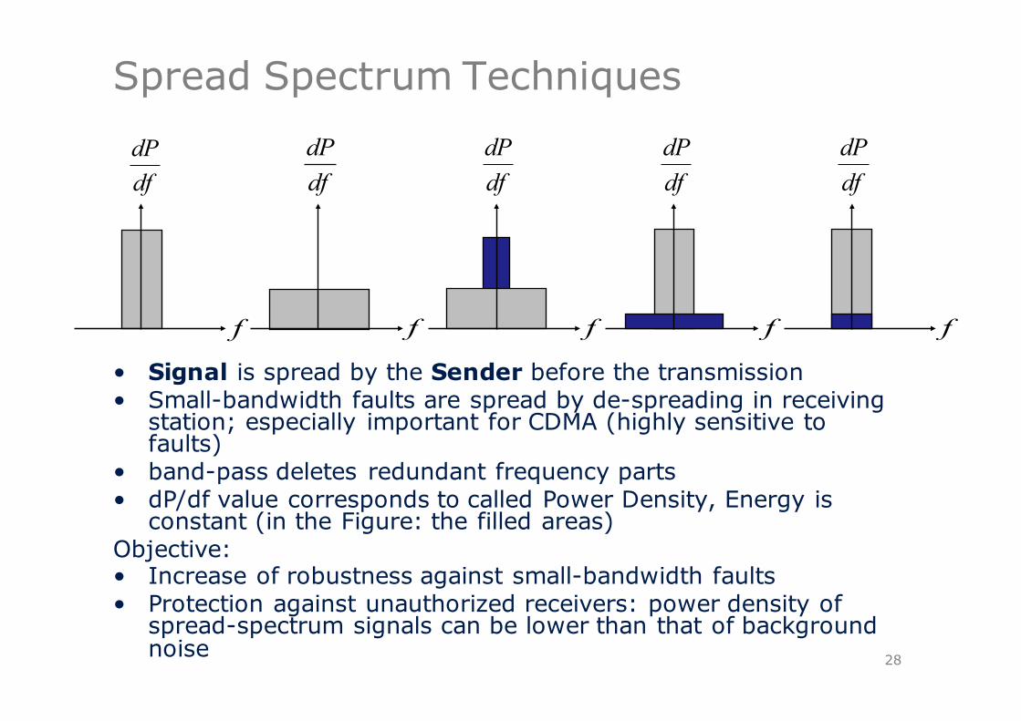
Spread Spectrum Techniques
• Signal is spread by the Sender before the transmission• Small-bandwidth faults are spread by de-spreading in receiving
station; especially important for CDMA (highly sensitive to faults)
• band-pass deletes redundant frequency parts• dP/df value corresponds to called Power Density, Energy is
constant (in the Figure: the filled areas)Objective:• Increase of robustness against small-bandwidth faults• Protection against unauthorized receivers: power density of
spread-spectrum signals can be lower than that of background noise 28
dfdP
f
dfdP
f
dfdP
f
dfdP
f
dfdP
f