department of electrical & electronics engineering files/iii-i mc lab cf.pdf · k. ability to...
TRANSCRIPT

Department of Electrical & Electronics Engineering
Course Title: MICROCONTROLLERS LAB
Following documents are available in Course File.
S.No. Points Yes No
1 Institute and Department Vision and Mission Statements Y
2 PEO & PO Mapping Y
3 Academic Calendar Y
4 Subject Allocation Sheet Y
5 Class Time Table, Individual Timetable (Single Sheet) Y
6 Syllabus Copy Y
7 Course Handout N
8 CO-PO Mapping Y
9 CO-Cognitive Level Mapping Y
10 Lecture Notes N
11 Tutorial Sheets With Solution N
12 Soft Copy of Notes/PPT/Slides Y
13 Sessional Question Paper and Scheme of Evaluation N
14 Best, Average and Weak Answer Scripts for Each Sessional Exam. (Photocopies)
N
15 Assignment Questions and Solutions N
16 Previous University Question Papers N
17 Result Analysis Y
18 Feedback From Students Y
19 Course Exit Survey N
20 CO Attainment for All Mids. N
21 Remedial Action. N
Course Instructor / Course Coordinator Course Instructor / Course Coordinator
(Name) (Signature)

Vision of the Institute
To be among the best of the institutions for engineers and technologists
with attitudes, skills and knowledge and to become an epicenter of creative
solutions.
Mission of the Institute
To achieve and impart quality education with an emphasis on practical skills
and social relevance.
Vision of the Department
To impart technical knowledge and skills required to succeed in life,
career and help society to achieve self-sufficiency.
Mission of the Department
To become an internationally leading department for higher learning.
To build upon the culture and values of universal science and contemporary
education.
To be a center of research and education generating knowledge and
technologies which lay groundwork in shaping the future in the fields of
electrical and electronics engineering.
To develop partnership with industrial, R&D and government agencies and
actively participate in conferences, technical and community activities.

Program Educational Objectives (B.Tech-EEE)
This programme is meant to prepare our students to professionally thrive and to lead.
During their progression:
PEO 1: Graduates will have a successful technical or professional careers, including supportive and
leadership roles on multidisciplinary teams.
PEO 2: Graduates will be able to acquire, use and develop skills as required for effective professional
practices.
PEO 3: Graduates will be able to attain holistic education that is an essential prerequisite for being a
responsible member of society.
PEO 4: Graduates will be engaged in life-long learning, to remain abreast in their profession and be leaders
in our technologically vibrant society.
Program Outcomes (B.Tech-EEE)
a. Ability to apply knowledge of mathematics, science, and engineering.
b. Ability to design and conduct experiments, as well as to analyze and interpret data.
c. Ability to design a system, component, or process to meet desired needs within realistic
constraints such as economic, environmental, social, political, ethical, health and safety,
manufacturability, and sustainability.
d. Ability to function on multi-disciplinary teams.
e. Ability to identify, formulates, and solves engineering problems.
f. Understanding of professional and ethical responsibility.
g. Ability to communicate effectively.
h. Broad education necessary to understand the impact of engineering solutions in a global,
economic, environmental, and societal context.
i. Recognition of the need for, and an ability to engage in life-long learning.
j. Knowledge of contemporary issues.
k. Ability to utilize experimental, statistical and computational methods and tools necessary for
engineering practice.
l. Graduates will demonstrate an ability to design electrical and electronic circuits, power
electronics, power systems; electrical machines analyze and interpret data and also an ability
to design digital and analog systems and programming them.

Name of the Course: MICROCONTROLLERS-LAB
Program Objectives:
S.No Course Objectives
1 To explain the concepts of 8086 instruction sets and architectures
2 To compare architectures of microprocessors and microcontrollers
3 To apply the instruction set of 8051 microcontrollers
4 To analyze assembly language programming concepts
5 To describe the various interrupt delays for microprocessors and microcontrollers
6 To interface various devices with 8051 microcontrollers
7 To create various programs to run several applications
Program Outcomes:
S.No Course Outcomes
1 Compare the functionally and architectures of microprocessors and microcontrollers
2 Analyze assembly language programming techniques
3 Explain the implementation of 8051 instruction set
4 Analyze assembly language programming concepts
5 Acquainted with design of microcontrollers
6 Interface various devices with microcontrollers
7 Design various programs to run several applications
Assessment methods:
1. Regular attendance to classes.
2. Written tests clearly linked to learning objectives
3. Classroom assessment techniques like tutorial sheets and assignments.
4. Seminars.
GUIDELINES TO STUDY THE COURSE/SUBJECT
Academic Year : 2018-2019
Semester : I
Name of the Program: B.Tech …EEE… Year: ……III……….. Section: A, B.
Course/Subject: ..............MICROCONTROLLERS-LAB................ Course Code: GR15A2059
Name of the Faculty: …PRASANTH KUMAR P....... Dept.: …EEE……
Designation: ASSISTANT PROFESSOR.
Guidelines to study the Course/ Subject: ……………MICROCONTROLLERS-LAB……………..
Course Design and Delivery System (CDD):
The Course syllabus is written into number of learning objectives and outcomes. These learning objectives and outcomes will be achieved through lectures, assessments,
assignments, seminars, presentations. Every student will be given an assessment plan, criteria for assessment, scheme of
evaluation and grading method. The Learning Process will be carried out through assessments of Knowledge, Skills and
Attitude by various methods and the students will be given guidance to refer to the text books, reference books.
The faculty be able to –
Understand the principles of Learning
Develop instructional objectives for a given topic
Prepare course, unit and lesson plans
Use appropriate teaching and learning aids like Slides and Paper Presentation.
Plan and deliver lectures effectively.
Provide the students of availability of the content in the textbooks and Internet.
Provide feedback to students using various methods of Assessments and tools of Evaluation
Act as a guide, advisor, counselor, facilitator, and motivator and not just as a teacher alone.
Signature of HOD Signature of faculty
Date: Date:

COURSE SCHEDULE
Academic Year : 2018-2019
Semester : I
Name of the Program: B.Tech …EEE… Year: ……III……….. Section: A, B.
Course/Subject: ............MICROCONTROLLERS-LAB................ Course Code: GR15A2059
Name of the Faculty: …PRASANTH KUMAR P....... Dept.: …EEE……
Designation: ASSISTANT PROFESSOR.
The Schedule for the whole Course / Subject is:
S. No. Description Total number of
Periods
1 Introduction to Arduino 4
2 Arduino Programming 4
3 LEDs and Switches 4
4 LCD 4
5 Serial Communication 4
6 Reading Sensors using Internal ADC 4
7 Device Control 4
8 Motor Control 4
9 Bluetooth 4
10 ZigBee 4
11 Real Time Clock (RTC) 4
Total No. of Instructional periods available for the course: ……44……. Periods
Signature of HOD Signature of faculty
Date: Date:

ILLUSTRATIVE VERBS FOR STATING
INSTRUCTIONAL OBJECTIVES
These verbs can also be used while framing questions for Continuous Assessment Examinations as well as for End –
Semester (final) Examinations
ILLUSTRATIVE VERBS FOR STATING GENERAL OBJECTIVES/OUTCOMES
ILLUSTRATIVE VERBS FOR STATING SPECIFIC OBJECTIVES/OUTCOMES:
A. COGNITIVE DOMAIN (KNOWLEDGE)
1 2 3 4 5 6
Knowledge Comprehension
Understanding Application
of knowledge &
comprehension
Analysis
Of whole w.r.t. its
constituents
Synthesis Evaluation
Judgment
Define
Identify
Label
List
Select
State
Convert
Describe (a
Procedure)
Distinguish
Estimate
Explain why/how
Generalize
Give examples
Illustrate
Summarize
Program
Deduce
Modify
Predict
Prepare
Relate
Show
Solve
Differentiate
Distinguish
Separate
Design
Generate
Reconstruct
Revise
Appraise
Compare
Conclude
Contrast
Criticize
Justify
Interpret
Support
B. AFFECTIVE DOMAIN (ATTITUDE) C. PSYCHOMOTOR DOMAIN (SKILLS)
Adhere
Assist
Attend
Change
Develop
Help
Influence
Resolve
Select
Serve
Share
Bend
Calibrate
Compress
Conduct
Connect
Convert
Decrease
Dissect
Draw
Extend
Feed
File
Grow
Increase
Insert
Keep
Elongate
Limit
Manipulate
Reset
Paint
Perform
Prepare
Remove
Replace
Report
Weigh
Set
Straighten
Strengthen
Time
Transfer
Type
Generate
Evaluate
Analyze
Design
Understand
Apply
Know
Comprehend
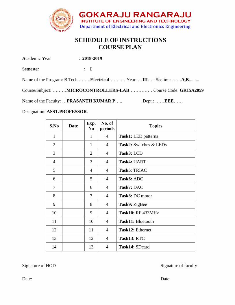
SCHEDULE OF INSTRUCTIONS
COURSE PLAN
Academic Year : 2018-2019
Semester : I
Name of the Program: B.Tech ……..Electrical……..… Year: …III….. Section: ……A,B.........
Course/Subject: ………MICROCONTROLLERS-LAB…………… Course Code: GR15A2059
Name of the Faculty: …PRASANTH KUMAR P….. Dept.: ……EEE……
Designation: ASST.PROFESSOR.
S.No Date Exp.
No
No. of
periods Topics
1 1 4 Task1: LED patterns
2 1 4 Task2: Switches & LEDs
3 2 4 Task3: LCD
4 3 4 Task4: UART
5 4 4 Task5: TRIAC
6 5 4 Task6: ADC
7 6 4 Task7: DAC
8 7 4 Task8: DC motor
9 8 4 Task9: ZigBee
10 9 4 Task10: RF 433MHz
11 10 4 Task11: Bluetooth
12 11 4 Task12: Ethernet
13 12 4 Task13: RTC
14 13 4 Task14: SDcard
Signature of HOD Signature of faculty
Date: Date:
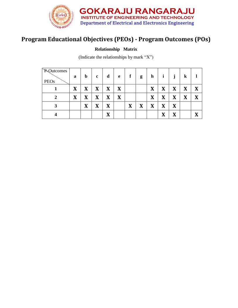
Program Educational Objectives (PEOs) - Program Outcomes (POs)
Relationship Matrix
(Indicate the relationships by mark “X”)
P-Outcomes
PEOs
a
b
c
d
e
f
g
h
i
j
k
l
1 X X X X X X X X X X
2 X X X X X X X X X X
3 X X X X X X X X
4 X X X X

Gokaraju Rangaraju Institute of Engineering and Technology (Autonomous)
Bachupally, Kukatpally, Hyderabad – 500 090, India.
GRIET/DAA/1H/G/18-19 05 May 2018
ACADEMIC CALENDAR Academic Year 2018-19
III & IV B.TECH – FIRST SEMESTER
S. No. EVENT PERIOD DURATION1 1st Spell of Instructions 02-07-2018 to 01-09-2018 9 Weeks 2 1st Mid-term Examinations 03-09-2018 to 05-09-2018 3 Days3 2nd Spell of Instructions 06-09-2018 to 24-10-2018 7 Weeks4 2nd Mid-term Examinations 25-10-2018 to 27-10-2018 3 Days5 Preparation 29-10-2018 to 06-11-2018 1 Week 3 Days6 End Semester Examinations (Theory/
Practicals) Regular/Supplementary08-11-2018 to 08-12-2018 4 Weeks 3 Days
7 Commencement of Second Semester,A.Y 2018-19
10-12-2018
III & IV B.TECH – SECOND SEMESTER
S. No. EVENT PERIOD DURATION1 1st Spell of Instruction 10-12-2018 to 02-02-2019 8 Weeks 2 1st Mid-term Examinations 04-02-2019 to 06-02-2019 3 Days3 2nd Spell of Instruction 07-02-2019 to 06-04-2019 8 Weeks 3 Days4 2nd Mid-term Examinations 08-04-2019 to 10-04-2019 3 Days5 Preparation 11-04-2019 to 17-04-2019 1 Week6 End Semester Examinations (Theory/
Practicals) Regular18-04-2019 to 08-05-2019 3 Weeks
7 Supplementary and Summer Vacation 09-05-2019 to 22-06-2019 6 Weeks 3 Days8 Commencement of First Semester, A.Y
2019-2024-06-2019
Copy to Director, Principal, Vice Principal, DOA, DOE, Balaji Kumar, DCGC, All HODs
(Dr. K. Anuradha) Dean of Academic Affairs
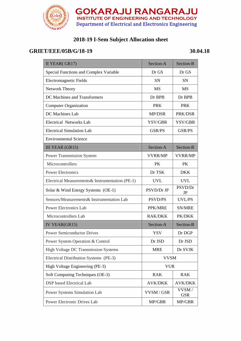
2018-19 I-Sem Subject Allocation sheet
GRIET/EEE/05B/G/18-19 30.04.18
II YEAR( GR17) Section-A Section-B
Special Functions and Complex Variable Dr GS Dr GS
Electromagnetic Fields SN SN
Network Theory MS MS
DC Machines and Transformers Dr BPB Dr BPB
Computer Organization PRK PRK
DC Machines Lab MP/DSR PRK/DSR
Electrical Networks Lab YSV/GBR YSV/GBR
Electrical Simulation Lab GSR/PS GSR/PS
Environmental Science
III YEAR (GR15) Section-A Section-B
Power Transmission System VVRR/MP VVRR/MP
Microcontrollers PK PK
Power Electronics Dr TSK DKK
Electrical Measurements& Instrumentation (PE-1) UVL UVL
Solar & Wind Energy Systems (OE-1) PSVD/Dr JP PSVD/Dr
JP
Sensors/Measurements& Instrumentation Lab PSVD/PS UVL/PS
Power Electronics Lab PPK/MRE SN/MRE
Microcontrollers Lab RAK/DKK PK/DKK
IV YEAR(GR15) Section-A Section-B
Power Semiconductor Drives YSV Dr DGP
Power System Operation & Control Dr JSD Dr JSD
High Voltage DC Transmission Systems MRE Dr SVJK
Electrical Distribution Systems (PE-3) VVSM
High Voltage Engineering (PE-3) VUR
Soft Computing Techniques (OE-3) RAK RAK
DSP based Electrical Lab AVK/DKK AVK/DKK
Power Systems Simulation Lab VVSM / GSR VVSM /
GSR
Power Electronic Drives Lab MP/GBR MP/GBR

I/I BEE(AICTE) A/B C/D/E
BEE ML
BEE KS
BEE MK
BEE MVK
BEE MNSR
Civil II/I (GR15) A B
ET PPK PPK
M.Tech (PE)(AICTE) A
Electric Drives System Dr DGP
Power Electronic Converters Dr TSK
Power Quality AVK
Electric and Hybrid Vehicles Dr BPB
Electrical Drives Laboratory AVK/GBR
Power Electronics Lab SN/MS
M.Tech (PS)(AICTE) A
Power System Analysis Dr JSD
Power System Dynamics Dr SVJK
Power Quality AVK
Electric and Hybrid Vehicles Dr BPB
Power System Steady State Analysis Lab VVSM/VVRR
Power System Dynamics Lab Dr
SVJK/YSV

COURSE TIME-TABLE
Academic Year : 2018-2019
Semester : I
Name of the Program: B.Tech …EEE… Year: ……III……….. Section: B.
Course/Subject: ................MICROCONTROLLERS-LAB................. Course Code: GR15A2059
Name of the Faculty: …PRASANTH KUMAR P....... Dept.: EEE
Designation: ASSISTANT PROFESSOR.
2018-19 Semester-I Time-Table
9
10
11
12
13
14
15
Monday
Tuesday MC-LAB
III-B1
12:00-03:00
Wednesday
Thursday
Friday
Saturday MC-LAB
III-B2
12:00-03:00
Signature of HOD Signature of faculty
Date: Date:


SYLLABUS
Academic Year : 2018-2019
Semester : I
Name of the Program: B.Tech …EEE… Year: ……III……….. Section: A, B.
Course/Subject: ................MICROCONTROLLERS-LAB...............Course Code: GR15A2059
Name of the Faculty: …PRASANTH KUMAR P.......Dept.: …EEE……
Designation: ASSISTANT PROFESSOR.
MICROCONTROLLERS-LAB
Course Code: GR15A2059 L-0 T-0 P-2 C-2 III Year I-Sem
List of experiments on 2G kit
Task1. LED patterns.
a) Blinking LEDs
b) Serial lights
c) Half on/Half off
d) Alternate on/off
Task2.Switches & LEDs
a) Press switch to make corresponding LED on
b) Press switch to make corresponding LED off
c) First switch press, last LED on
d) First switch press, last LED off
Task3.LCD
a) Character &string display on LCD,
b) SW1-Display strring1 on first line of LCD,
c) SW2-Display strring1 on first line of LCD, SW2
Task4.UART
a) Echo Program,
b) Take command from PC & glow corresponding LED,
c) Press Switch & display switch number on PC,
d) Display data received by UART on LCD
Task5. TRIAC
a) 220V AC bulb switch on/off
b) 220V AC fan speed control with fixed step size

Task6.ADC
a) Raw ADC value display on LCE
b) Raw ADC value display on Hyper Terminal
c) Engineering unit conversion and display on LCD
d) Engineering unit conversion and display on Hyper Terminal
e) Limit checking for temperature value and switching on fan using triac
f) Limit checking for ambient light value and switching on light using triac.
Task7.DAC
a) Fixed step incremented DAC, output seen on multi-meter
b) DAC input value received from Hyper Terminal
c) DAC input value taken from switches
Task8.DC motor
a) DC motor control-CW, CCW and stop using switches
b) DC motor control- CW, CCW and stop using commands received from Hyper Terminal
Task9. ZigBee
a) Receive data on ZigBee from PC ZigBee dongle and display data on LEDs
b) Receive data on ZigBee from PC ZigBee dongle and display data on LCD
c) Read ADC and transmit data using ZigBee
d) TRIAC based control of fan and light using data received on ZigBee
Task10. RF 433MHz
a) Receive data on RF from another kit with RF transmitter. Connect PCs to both kits. Type in data in
Hyper Terminal of Transmitter kit & see on Hyper Terminal of Receiver kit.
b) Read switches on transmitter kit, send their status on RF to receiver kit and control motor using
switch status.
Task11.Bluetooth
a) Transfer data to PC using Bluelink.
b) Receive data from PC using Bluelink & display on LCD
c) Transfer data from mobile phone (using a J2ME app) and receive using Blue link and control motor
operation.
d) Transfer data from mobile phone (using a J2ME app) and receive using Bluelink and control electrical
appliance operation.
Task12. Ethernet
a) Transfer data to PC using WIZI05SR and display on Hyper Terminal.
b) Implement an embedded web server.
c) Task13. RTC
d) Read and display RTC data on LCD.
e) Read and display RTC data on Hyper Terminal.
f) Set RTC using Hyper terminal and display data on Hyper Terminal.

g) Implement an Event Logger with Time Stamp display.
Task14. SD card
a) Transfer data to PC, store on SD-card and retrieve it back (block transfer)
b) Implement FAT file system on SD card.
c) Implement data acquisition system and store data in a CSV file on SD card with time stamp.
Note: A minimum of 10 (Ten) experiments must be performed and recorded by the candidate to attain
eligibility for Practical Examination.
Lab methodologies:
Assignments
Lab experiments with Arduino software
Signature of HOD Signature of faculty
Date: Date:

COURSE OUTCOME AND PROGRAM OUTCOME MAPPING
P-Outcomes
C-Outcomes
a
b
c
d
e
f
g
h
i
j
k
l
1 X X X X X
2 X X X X X X
3 X X X X X X
4 X X X X X X
5 X X X X X
6 X X X X X X
7 X X X X X

MICROCONTROLLERS
CO – Cognitive Level Mapping
C 1 2 3 4 5 6
CO-1 X X
CO-2 X X
CO-3 X X
CO-4 X X
CO-5 X X
CO-6 X X X
CO-7 X X
1-REMEMBER
2-UNDERSTAND
3-APPLY
4-ANALYSE
5-EVALUATE
6-CREATE

EVALUATION STRATEGY
Academic Year : 2018-19
Semester : I
Name of the Program : B. Tech Year: III Section: A
Course/Subject : MICROCONTROLLERS Course Code: GR15A2055
Name of the Faculty : P Prasanth Kumar Dept.: ……EEE…………
Designation : ASST PROFESSOR
1. TARGET:
a) Percentage for pass: 100%
b) Percentage of class: 100%
2. COURSE PLAN & CONTENT DELIVERY
PPT presentation of the Lectures
Solving exercise programs
Model questions
3. METHOD OF EVALUATION
1. Continuous Assessment Examinations (CAE-I, CAE-II)
2. Assignments
3. Quiz
4. Class tests
5. Semester/End Examination
Signature of HOD Signature of faculty
Date: Date:

B.Tech EEE IIIYEAR I SEM RESULT ANALYSIS OF 2016-2020 BATCH
ACADEMIC YEAR 2018-2019 TOTAL. NO. OF STUDENTS REGISTERED = 142
Subj
ect
Total
No. of
students
appeared
No. of
students
passed
No. of
students
failed
Grade Points
< 5
5
6
7
8
9
10
Pass
percentag
e
MC 142 116 26 07 13 15 20 32 27 02 81.69%
MC
Lab 142 141 01 00 01 00 00 09 26 105 99.29%
PTS 142 128 14 01 12 12 14 30 34 25 90.14%
EMI 142 128 14 08 11 08 12 32 31 26 90.14%
PE 142 135 07 03 08 11 08 27 37 41 95.07%
SMI
Lab 142 140 02 06 10 02 04 12 17 89 98.59%
PE
Lab 142 140 02 00 01 02 07 27 31 72 98.59%
SW
E 142 125 17 06 11 16 09 44 29 10 88.02%
Overall pass (passed in all subjects) = 107/142 (75.35%)
Faculty
Power Transmission System V Vijaya Rama Raju, M Prashanth
Microcontrollers P Prashanth Kumar
Electrical Measurements&
Instrumentation U Vijaya Lakshmi
Power Electronics Dr T Suresh Kumar,D Karuna Kumar
Solar and Wind Energy Systems P Sri Vidya Devi /Dr J Praveen
Sensors/Measurements&
Instrumentation Lab P Srividya Devi/U Vijaya Lakshmi/P Sirisha
Power Electronics Lab Dr T Suresh Kumar/Syed Sarfaraz Nawaz/M Rekha
Microcontrollers Lab R Anil Kumar/MN Sandhya Rani
ARREARS POSITION – CURRENT YEAR
Descript
ion All pass
One
Arrear
Two
Arrears
Three
Arrears
More than Three
Arrears % of pass
142 107 10 16 03 06 75.35%
Performance overall Class Three Toppers
ROLL NO. NAME PERCENTAGE(SGPA) 16241A0259
VIPPARTHI SOWMYA 10
16241A0274
16241A0290
17245A0205
17245A0214
17245A0221
INDURI PAVANI
MANGANAPALLY ROOPA
CHILUKA PRANAVI
K VAISHNAVI
P SWATHI
9.84
16241A0257
UNDETY MOUNIKA 9.72
HOD,EEE

Name of the Instructor P Prasanth Kumar
Faculty ID 1055
Branch EEE
Class and Semester/Section III / I / B
Academic Year 2018 19
Subject Title MC Lab
Total No. of Responses/class strength 52/71
3.1956521739130435
3.1956521739130435
3.2826086956521738
3.152173913043478
3.1956521739130435
3.2173913043478262
3.2391304347826089
3.1956521739130435
3.152173913043478
3.2173913043478262

GOKARAJU RANGARAJU Institute of Engineering and Technology
(Autonomous)
MICROCONTROLLERS LABORATORY
Manual
Name
Reg No
Branch
Year and Section


GOKARAJU RANGARAJU
Institute of Engineering and Technology
(Autonomous)
CERTIFICATE
This is to certify that it is a bonafide record of practical work done by Mr./Ms.
___________________________, Reg No. __________________ in the
“MICROCONTROLLERS LABORATORY” in I-Semester of III-year during
20__ to 20__.
Internal Examiner
Signature
External Examiner
Signature
Head of the Department
Signature


MICROCONTROLLERS LABORATORY
Index
Exp
No. Experiment Name
Page
No. Date Signature
1 Introduction to Arduino 1
2 Arduino Programming 11
3 LEDs and Switches 21
4 LCD 25
5 Serial Communication 31
6 Reading Sensors using Internal ADC 33
7 Device Control 37
8 Motor Control 41
9 Bluetooth 45
10 ZigBee 47
11 Real Time Clock (RTC) 49
12 Color LCD 57
Additional Experiments
13 AVR Programming 61
14 Digital I/O 62
15 Programs 64
16 Serial Communication 66
17 Internal ADC 71
18 Interrupts 74
19 Timers 77


Microcontrollers Lab
GRIET-EEE
Introduction to Arduino
The lab will be based on the Arduino Uno. The Arduino Uno is a microcontroller board
based on the ATmega328. It has 14 digital input/output pins (of which 6 can be used as PWM
outputs), 6 analog inputs, a 16 MHz ceramic resonator, a USB connection, a power jack, an ICSP
header, and a reset button. It contains everything needed to support the microcontroller; simply
connect it to a computer with a USB cable or power it with a AC-to-DC adapter or battery to get
started.
Digital pins
(0 to 13)
USB
Connector
Pin 0 – RX
Pin 1 - TX
Power jack
Power supplies Analog pins
(A0 to A5)
1

Microcontrollers Lab
GRIET-EEE
Features of Uno board
Microcontroller ATmega328
Operating Voltage 5V
Input Voltage (recommended) 7-12V
Input Voltage (limits) 6-20V
Digital I/O Pins 14 (of which 6 provide PWM output)
Analog Input Pins 6
DC Current per I/O Pin 40 mA
DC Current for 3.3V Pin 50 mA
Flash Memory 32 KB (ATmega328) of which 0.5 KB used by boot loader
SRAM 2 KB (ATmega328)
EEPROM 1 KB (ATmega328)
Clock Speed 16 MHz
Power
The Arduino Uno can be powered via the USB connection or with an external power
supply. The power source is selected automatically.
External (non-USB) power can come either from an AC-to-DC adapter (wall-wart) or
battery. The adapter can be connected by plugging a 2.1mm center-positive plug into the board's
power jack. Leads from a battery can be inserted in the Gnd and Vin pin headers of the POWER
connector.
The board can operate on an external supply of 6 to 20 volts. If supplied with less than
7V, however, the 5V pin may supply less than five volts and the board may be unstable. If using
more than 12V, the voltage regulator may overheat and damage the board. The recommended
range is 7 to 12 volts.
2

Microcontrollers Lab
GRIET-EEE
The power pins are as follows:
• VIN. The input voltage to the Arduino board when it's using an external power source (as
opposed to 5 volts from the USB connection or other regulated power source). You can supply
voltage through this pin, or, if supplying voltage via the power jack, access it through this pin.
• 5V.This pin outputs a regulated 5V from the regulator on the board. The board can be supplied
with power either from the DC power jack (7 - 12V), the USB connector (5V), or the VIN pin of
the board (7-12V).
• 3V3. A 3.3 volt supply generated by the on-board regulator. Maximum current draw is 50 mA.
• GND. Ground pins.
Each of the 14 digital pins (pins 0 to 13) on the Uno can be used as an input or output, using
pinMode(), digitalWrite(), and digitalRead() functions. They operate at 5 volts. Each pin can
provide or receive a maximum of 40 mA and has an internal pull-up resistor (disconnected by
default) . In addition, some pins have specialized functions:
• Serial: 0 (RX) and 1 (TX). Used to receive (RX) and transmit (TX) TTL serial data.
These pins are connected to the corresponding pins of the ATmega8U2 USB-to-TTL
Serial chip.
• External Interrupts: 2 and 3. These pins can be configured to trigger an interrupt on a
low value, a rising or falling edge, or a change in value.
• PWM: 3, 5, 6, 9, 10, and 11. Provide 8-bit PWM output with the analogWrite() function.
• SPI: 10 (SS), 11 (MOSI), 12 (MISO), 13 (SCK). These pins support SPI
communication using the SPI library.
• LED: 13. There is a built-in LED connected to digital pin 13. When the pin is HIGH
value, the LED is on, when the pin is LOW, it's off.
The Uno has 6 analog inputs, labeled A0 through A5, each of which provide 10 bits of
resolution (i.e. 1024 different values). By default they measure from ground to 5 volts, though it
is possible to change the upper end of their range using the AREF pin and the analogReference()
function.
Additionally, some pins have specialized functionality:
• TWI: A4 or SDA pin and A5 or SCL pin. Support TWI communication using the Wire
library.
3

Microcontrollers Lab
GRIET-EEE
ATmega168/328-Arduino Pin Mapping
4

Microcontrollers Lab
GRIET-EEE
Arduino Programming
Click on the Arduino executable which has the Arduino logo
The following screen comes up:
The programs written for Arduino are called sketches. For the sketch to work on the Arduino
Uno, there are two hardware related settings need to be done in the Arduino IDE –
• Board
• Serial Port
5

Microcontrollers Lab
GRIET-EEE
For selecting the board, go to the Tools tab and select Board. From the menu select Uno.
When you connect your Arduino Uno to the USB port of your laptop, it will be mapped
as a serial port.
6

Microcontrollers Lab
GRIET-EEE
To know the serial port to which your Arduino is mapped, follow the following procedure:
Right click on My Computer
Select the Manage option
In the pop up screen for Computer Management, select the Device Manager
Expand the Ports item; the Arduino Uno will appear as one of the drop down items
7
Microcontrollers Lab
GRIET-EEE
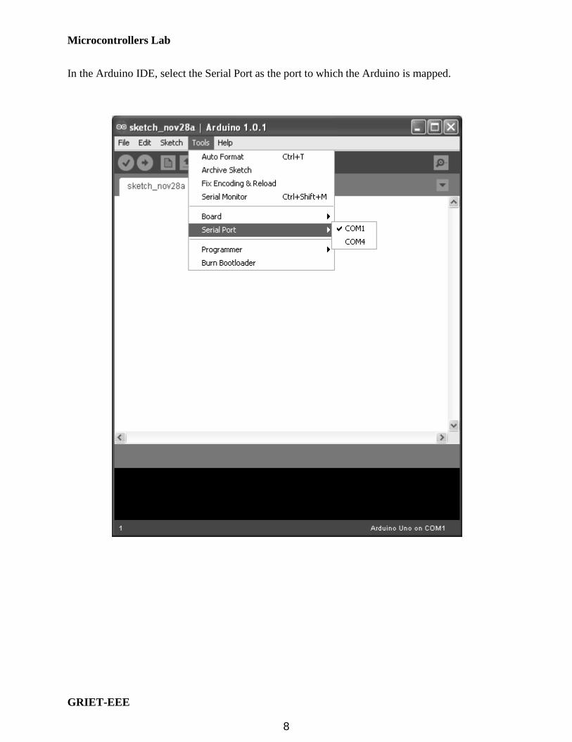
In the Arduino IDE, select the Serial Port as the port to which the Arduino is mapped.
8

Microcontrollers Lab
GRIET-EEE
The basic structure of the Arduino sketch is fairly simple and has two required functions:
void setup()
statements;
void loop()
statements;
Where setup() is the preparation, loop() is the execution. Both functions are required for
the program to work. The setup function should follow the declaration of any variables at the
very beginning of the program. It is the first function to run in the program, is run only once, and
is used to set pin Mode or initialize serial communication.
The loop function follows next and includes the code to be executed continuously –
reading inputs, triggering outputs, etc. This function is the core of all Arduino programs and does
the bulk of the work.
setup() The setup() function is called once when your program starts. Use it to initialize pin
modes, or begin serial. It must be included in a program even if there are no statements to run.
void setup()
pinMode(pin, OUTPUT); // sets the 'pin' as output
loop()
After calling the setup() function, the loop() function does precisely what its name suggests, and
loops consecutively, allowing the program to change, respond, and control the Arduino board.
9

Microcontrollers Lab
GRIET-EEE
void loop()
digitalWrite(pin, HIGH); // turns 'pin' on
delay(1000); // pauses for one second
digitalWrite(pin, LOW); // turns 'pin' off
delay(1000); // pauses for one second
pinMode(pin, mode)
Used in void setup() to configure a specified pin to behave either as an INPUT or an
OUTPUT.
pinMode(pin, OUTPUT); // sets ‘pin’ to output
There are also convenient pullup resistors built into the Atmega chip that can be accessed from
software. These built-in pullup resistors are accessed in the following manner:
pinMode(pin, INPUT); // set ‘pin’ to input
digitalWrite(pin, HIGH); // turn on pullup resistors
Pullup resistors would normally be used for connecting inputs like switches. Notice in the above
example it does not convert pin to an output, it is merely a method for activating the internal
pull-ups.
Pins configured as OUTPUT can provide 40 mA (milliamps) of current to other
devices/circuits. This is enough current to brightly light up an LED (don't forget the series
resistor), but not enough current to run most relays, solenoids, or motors.
Short circuits on Arduino pins and excessive current can damage or destroy the output
pin, or damage the entire Atmega chip. It is often a good idea to connect an OUTPUT pin to an
external device in series with a 470Ω or 1KΩ resistor.
digitalRead(pin)
Reads the value from a specified digital pin with the result either HIGH or LOW. The pin can be
specified as either a variable or constant (0-13).
value = digitalRead(Pin); // sets 'value' equal to the input pin
10
Microcontrollers Lab
GRIET-EEE
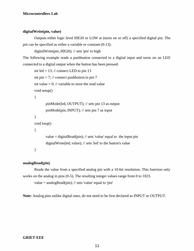
digitalWrite(pin, value)
Outputs either logic level HIGH or LOW at (turns on or off) a specified digital pin. The
pin can be specified as either a variable or constant (0-13).
digitalWrite(pin, HIGH); // sets 'pin' to high
The following example reads a pushbutton connected to a digital input and turns on an LED
connected to a digital output when the button has been pressed:
int led = 13; // connect LED to pin 13
int pin = 7; // connect pushbutton to pin 7
int value = 0; // variable to store the read value
void setup()
pinMode(led, OUTPUT); // sets pin 13 as output
pinMode(pin, INPUT); // sets pin 7 as input
void loop()
value = digitalRead(pin); // sets 'value' equal to the input pin
digitalWrite(led, value); // sets 'led' to the button's value
analogRead(pin)
Reads the value from a specified analog pin with a 10-bit resolution. This function only
works on the analog in pins (0-5). The resulting integer values range from 0 to 1023.
value = analogRead(pin); // sets 'value' equal to 'pin'
Note: Analog pins unlike digital ones, do not need to be first declared as INPUT or OUTPUT.
11

Microcontrollers Lab
GRIET-EEE
analogWrite(pin, value)
Writes a pseudo-analog value using hardware enabled pulse width modulation (PWM) to
an output pin marked PWM. On Uno, this function works on pins 3, 5, 6, 9, 10, and 11. The
value can be specified as a variable or constant with a value from 0-255.
analogWrite(pin, value); // writes 'value' to analog 'pin'
A value of 0 generates a steady 0 volts output at the specified pin; a value of 255
generates a steady 5 volts output at the specified pin. For values in between 0 and 255, the pin
rapidly alternates between 0 and 5 volts - the higher the value, the more often the pin is HIGH (5
volts). For example, a value of 64 will be 0 volts three-quarters of the time, and 5 volts one
quarter of the time; a value of 128 will be at 0 half the time and 255 half the time; and a value of
192 will be 0 volts one quarter of the time and 5 volts three-quarters of the time.
Because this is a hardware function, the pin will generate a steady wave after a call to
analogWrite in the background until the next call to analogWrite (or a call to digitalRead or
digitalWrite on the same pin).
Note: Analog pins unlike digital ones do not need to be first declared as INPUT or OUTPUT.
The following example reads an analog value from an analog input pin, converts the
value by dividing by 4, and outputs a PWM signal on a PWM pin:
int led = 10; // LED with 220 resistor on pin 10
int pin = A0; // potentiometer on analog pin 0
int value; // value for reading
void setup() // no setup needed
void loop()
value = analogRead(pin); // sets 'value' equal to 'pin'
value /= 4; // converts 0-1023 to 0-255
analogWrite(led, value); // outputs PWM signal to led
12

Microcontrollers Lab
GRIET-EEE
delay(ms)
Pauses a program for the amount of time as specified in milliseconds, where 1000 equals
1 second.
delay(1000); // waits for one second
millis()
Returns the number of milliseconds since the Arduino board began running the current program
as an unsigned long value.
value = millis(); // sets ‘value’ equal to millis()
Note: This number will overflow (reset back to zero), after approximately 9 hours.
Serial.begin(rate)
Opens serial port and sets the baud rate for serial data transmission. The typical baud rate for
communicating with the computer is 9600 although other speeds are supported.
void setup()
Serial.begin(9600); // opens serial port
// sets data rate to 9600 bps
Note: When using serial communication, digital pins 0 (RX) and 1 (TX) cannot be used at the
same time.
Serial.println(data)
Prints data to the serial port, followed by an automatic carriage return and line feed. This
command takes the same form as Serial.print(), but is easier for reading data on the Serial
Monitor.
Serial.println(analogValue); // sends the value of
// 'analogValue'
Note: For more information on the various permutations of the Serial.println() and Serial.print()
functions please refer to the Arduino website.
13

Microcontrollers Lab
GRIET-EEE
The following simple example takes a reading from analog pin0 and sends this data to the
computer every 1 second.
void setup()
Serial.begin(9600); // sets serial to 9600bps
void loop()
Serial.println(analogRead(A0)); // sends analog value
delay(1000); // pauses for 1 second
Verify button Upload button Serial Monitor
After entering your program, click on the Verify button for compilation. If there are
errors, the line numbers of the errors are shown in the bottom window. Correct the errors. After
successful verification, upload your program to the Arduino using the Upload button. A common
cause for failure in uploading is that your Arduino is not connected to a different COM port than
the one shown in the Arduino IDE.
14

Microcontrollers Lab
GRIET-EEE
Introduction
LEDs and Switches
The GRIET LED and switches shield has 6 LEDs and 6 switches. The cathodes of the
LEDs are grounded and the anodes are connected to Arduino Uno pins through resistors. The
switches when pressed will ground the connected Uno pins. The Uno pins connected to the
switches should be made inputs with pull-ups enabled. The required 5V supply and ground for
the shield are transferred from the Arduino Uno base board
Pin-out
LEDs and switches Arduino Uno pins ATmega328 pin
LED1 8 PB0
LED2 9 PB1
LED3 10 PB2
LED4 11 PB3
LED5 12 PB4
LED6 13 PB5
S1 2 PD2
S2 3 PD3
S3 4 PD4
S4 5 PD5
S5 6 PD6
S6 7 PD7
15

Microcontrollers Lab
GRIET-EEE
Schematic
16

Microcontrollers Lab
GRIET-EEE
Bill of Materials
Part Value Device Package Library Sheet
IC1 Arduino Shield
ARDUINO2009_PIN_22 ARDUINO2009_2 arduino01 1
LED1 LEDCHIPLED_1206 CHIPLED_1206 led 1
LED2 LEDCHIPLED_1206 CHIPLED_1206 led 1
LED3 LEDCHIPLED_1206 CHIPLED_1206 led 1
LED4 LEDCHIPLED_1206 CHIPLED_1206 led 1
LED5 LEDCHIPLED_1206 CHIPLED_1206 led 1
LED6 LEDCHIPLED_1206 CHIPLED_1206 led 1
R1 330R R-US_R1206 R1206 rcl 1
R2 330R R-US_R1206 R1206 rcl 1
R3 330R R-US_R1206 R1206 rcl 1
R4 330R R-US_R1206 R1206 rcl 1
R5 330R R-US_R1206 R1206 rcl 1
R6 330R R-US_R1206 R1206 rcl 1
S1 10XX Tactile
10-XX B3F-10XX switch- omron
1
S1 10XX Tactile
10-XX B3F-10XX switch- omron
1
S1 10XX Tactile
10-XX B3F-10XX switch- omron
1
S1 10XX Tactile
10-XX B3F-10XX switch- omron
1
S1 10XX Tactile
10-XX B3F-10XX switch- omron
1
S1 10XX Tactile
10-XX B3F-10XX switch- omron
1
17

Microcontrollers Lab
GRIET-EEE
Arduino program
The program will read the status of one switch and use it to control an LED – LED is on
when the switch is pressed and off when the switch is not pressed. LED1 and SW1 are used in
the program
int LED1 = 8;
int S1 = 2;
void setup( )
pinMode(LED1,OUTPUT);
pinMode(S1,INPUT_PULLUP);
void loop( )
Exercises
int status;
status = digitalRead(S1);
if(status == LOW)
digitalWrite(LED1,HIGH);
else
digitalWrite(LED1,LOW);
1. Write an Arduino program to control LED6 using switch SW6
2. Write an Arduino program to control the six LEDs using the six corresponding switches
18

Microcontrollers Lab
GRIET-EEE
Introduction
LCD
The GRIET LCD shield has the following resources
• 2x16 LCD
• LM35 temperature sensor
• LDR(Light Dependent Resistor)
• 2 LEDs
The 2x16 LCD uses the 4-bit interface. The RD/WR pin of the LCD is grounded so that write
is permanently enabled. There is a potentiometer for adjusting the contrast. Adjust the pot till
you see a strip of dark blocks in the first line of the LCD. The LM35 is connected to the A5
analog input pin of Uno. The LDR forms part of a potential divider circuit whose output is given
to A4 analog input pin of Uno.
Pin-out
LCD, sensors & LEDs Arduino Uno pins ATmega328 pin
LCD Enable 11 PB3
LCD Register Select(RS) 12 PB4
DB4 4 PD4
DB5 5 PD5
DB6 6 PD6
DB7 7 PD7
LM35 A5 PC5
LDR A4 PC4
LED1 8 PB0
LED2 10 PB2
19

Microcontrollers Lab
GRIET-EEE
W
0
Schematic
Bill of Materials
Part Value Device Package Library Sheet
IC1 Arduino Shield ARDUINO2009_PIN_22 ARDUINO2 09_2 arduino01 1
LCD LCD-16X2
LCD-16X2
LCD-16X2 SparkFun 1
LDR LDR LDR LDR BHolder 1
LED1
LEDCHIPLED_1206
CHIPLED_1206 led 1
LED2 LEDCHIPLED_1206 CHIPLED_1206 led 1
LM35 LM35CZ
LM35CZ
TO127P254X495-3P LM35 1
R1 5K R-TRIMM3296 RTRIM3296W rcl 1
R2
R-US_0204/7
0204/7 rcl 1
R3 330R R-US_R1204/7 R1204/7 rcl 1
R4 330R
R-US_R1204/7
R1204/7 rcl 1
20

Microcontrollers Lab
GRIET-EEE
Arduino program The program is to write “Hello World” in the first line of the LCD. We use the LiquidCrystal.h
library in the program.
#include <LiquidCrystal.h>
/* RS 12
E 11
D4 4
D5 5
D6 6
D7 7 */
LiquidCrystal lcd(12,11,4,5,6,7);
void setup()
lcd.begin(16,2);
lcd.print(" hello, world");
void loop()
21

Microcontrollers Lab
GRIET-EEE
LCD library functions LiquidCrystal()
Description
Creates a variable of type LiquidCrystal. The display can be controlled using 4 or 8 data lines. If
the former, omit the pin numbers for d0 to d3 and leave those lines unconnected. The RW pin
can be tied to ground instead of connected to a pin on the Arduino; if so, omit it from this
function's parameters.
Syntax
LiquidCrystal(rs, enable, d4, d5, d6, d7) LiquidCrystal(rs,
rw, enable, d4, d5, d6, d7) LiquidCrystal(rs, enable, d0, d1,
d2, d3, d4, d5, d6, d7) LiquidCrystal(rs, rw, enable, d0, d1,
d2, d3, d4, d5, d6, d7)
Parameters
rs: the number of the Arduino pin that is connected to the RS pin on the LCD
rw: the number of the Arduino pin that is connected to the RW pin on the LCD (optional)
enable: the number of the Arduino pin that is connected to the enable pin on the LCD
d0, d1, d2, d3, d4, d5, d6, d7: the numbers of the Arduino pins that are connected to the
corresponding data pins on the LCD. d0, d1, d2, and d3 are optional; if omitted, the LCD will be
controlled using only the four data lines (d4, d5, d6, d7).
22

Microcontrollers Lab
GRIET-EEE
begin()
Description
Specifies the dimensions (width and height) of the display.
Syntax
lcd.begin(cols, rows)
Parameters
lcd: a variable of type LiquidCrystal
cols: the number of columns that the display has
rows: the number of rows that the display has
setCursor()
Description
Position the LCD cursor; that is, set the location at which subsequent text written to the LCD will
be displayed.
Syntax
lcd.setCursor(col, row)
Parameters
lcd: a variable of type LiquidCrystal
col: the column at which to position the cursor (with 0 being the first column)
row: the row at which to position the cursor (with 0 being the first row)
Exercise
1. Write an Arduino program to write your name in the first line of the LCD
2. Write an Arduino program to write your name in the first line of the LCD and your roll
number in the second line
23

Microcontrollers Lab
GRIET-EEE
24

Microcontrollers Lab
GRIET-EEE
Introduction
Serial communication
The Arduino Uno board is capable of serial communication used for communication
between the Arduino board and a computer or other devices. The Uno has a single serial port
(also known as a UART or USART): Serial. It communicates on digital pins 0 (RX) and 1 (TX)
as well as with the computer via USB. Thus, if you use these functions, you cannot also use pins
0 and 1 for digital input or output.
You can use the Arduino environment's built-in serial monitor to communicate with an
Arduino board. Click the serial monitor button in the toolbar and select the same baud rate used
in the call to begin().
Functions
begin()
Description
Sets the data rate in bits per second (baud) for serial data transmission. For communicating with
the computer, use one of these rates: 300, 1200, 2400, 4800, 9600, 14400, 19200, 28800, 38400,
57600, or 115200. Syntax
Serial.begin(speed) println()
Description
Prints data to the serial port as human-readable ASCII text followed by a carriage return
character (ASCII 13, or '\r') and a newline character (ASCII 10, or '\n'). This command takes the
same forms as Serial.print().
25

Microcontrollers Lab
GRIET-EEE
Syntax
Serial.println(val)
Serial.println(val, format)
Parameters
val: the value to print - any data type
format: specifies the number base (for integral data types) or number of decimal places (for
floating point types)
Returns
byte
println() will return the number of bytes written, though reading that number is optional Example:
void setup()
// open the serial port at 9600 bps
Serial.begin(9600);
void loop()
println(“Hello World”);
delay(1000);
Exercises
1. Write an Arduino program to write your name
2. Write an Arduino program to write your name in the first line and your roll number in the
second line
3. Write an echo program to echo whatever is sent from the computer back to the computer
26

Microcontrollers Lab
GRIET-EEE
Introduction
Reading sensors using internal ADC
The GRIET LCD shield which has a temperature sensor and an ambient light sensor is
used in this experiment. The temperature sensor is connected to pin A5 and the ambient light
sensor is connected to pin A4 of Uno. To use the internal ADC, the function AnalogRead() is
used.
Functions analogRead()
Description
Reads the value from the specified analog pin. The Arduino Uno board contains a 6
channel, 10-bit analog to digital converter. This means that it will map input voltages between 0
and 5 volts into integer values between 0 and 1023. This yields a resolution between readings of:
5 volts / 1024 units or, .0049 volts (4.9 mV) per unit.
It takes about 100 microseconds (0.0001 s) to read an analog input, so the maximum
reading rate is about 10,000 times a second.
Syntax
analogRead(pin) Parameters
pin: the number of the analog input pin to read from (A0 to A5 on Uno) Returns
int (0 to 1023)
27

Microcontrollers Lab
GRIET-EEE
W
0
Schematic
Part Value Device Package Library Sheet
IC1 Arduino Shield ARDUINO2009_PIN_22 ARDUINO2 09_2 arduino01 1
LCD LCD-16X2
LCD-16X2
LCD-16X2 SparkFun 1
LDR LDR LDR LDR BHolder 1
LED1
LEDCHIPLED_1206
CHIPLED_1206 led 1
LED2 LEDCHIPLED_1206 CHIPLED_1206 led 1
LM35 LM35CZ
LM35CZ
TO127P254X495-3P LM35 1
R1 5K R-TRIMM3296 RTRIM3296W rcl 1
R2
R-US_0204/7
0204/7 rcl 1
R3 330R R-US_R1204/7 R1204/7 rcl 1
R4 330R
R-US_R1204/7
R1204/7 rcl 1
28

Microcontrollers Lab
GRIET-EEE
Arduino program
int val = 0; // variable to store the value read
void setup()
Serial.begin(9600); // setup serial
void loop()
val = analogRead(A5); // read the input pin
Serial.println(val); // debug value
Exercise
1. Write an Arduino program to read the LM35 sensor, convert the value into temperature
and display it on the serial monitor
2. Write an Arduino program to read the LM35 sensor, convert the value into temperature
and display it on the LCD
3. Write an Arduino program to read the LDR sensor and display it on the serial monitor.
Switch on LED1 when light is high and switch off the LED when light is low
29

Microcontrollers Lab
GRIET-EEE
30

Microcontrollers Lab
GRIET-EEE
1 A
m e
A
m
c
o
Introduction
Device Control
The GRIET Triac shield is used for device control. Two devices can be controlled by the
Triac shield. Each channel will have an Arduino pin connected to an opto-isolator and a triac.
The main purpose of an opto-isolator is to prevent high voltages on one side of the circuit from
damaging components on the other side.
Schematic diagram of an opto-isolator showing sour e
of light (LED) on the left, dielectric barrier in the center,
and sensor (phototransistor) on the right.
The triac is a three-terminal semiconductor device for controlling current. It is an ideal
device to use for AC switching applications because it can control the current flow over both
halves of an alternating cycle.
On the TRIAC sy bol there are three ter inals . These
are the Gate and two other terminals. These other
TRIAC terminals are often ref rred to as an "Anode" r
"Main Terminal". As the TRI C has two of these they
are labelled either Anode 1 and Anode 2 or Main
Terminal, MT1 and MT2.
Pin-out
Device Arduino Uno pins ATmega328 pin
Device 4 PC4
Device2 A5 PC5
31

Microcontrollers Lab
GRIET-EEE
Schematic
Phase and neutral of 220V AC mains are connected to terminals X1-1 and X1-2 Two AC
operated devices are connected to X2-1, X2-2 and X3-1,X3-2 respectively
32

Microcontrollers Lab
GRIET-EEE
Bill of Materials
Part Value Device Package Library Sheet
IC1 Arduino Shield ARDUINO2009_PIN_22 ARDUINO2009_2 arduino01 1
OK1 MOC3032M MOC3032M DIL06 optocoupler 1
OK2 MOC3032M MOC3032M DIL06 optocoupler 1
R1 10K R-US_0204/7 0204/7 rcl 1
R2 10K R-US_0204/7 0204/7 rcl 1
R3 10K R-US_R1204/7 0204/7 rcl 1
R4 10K R-US_R1204/7 0204/7 rcl 1
T1 BT138-V BT138-V TO220BV triac 1
T2 BT138-V BT138-V TO220BV triac 1
X1 AK500/2 AK500/2 con-ptr500 1
X2 AK500/2 AK500/2 con-ptr500 1
X3 AK500/2 AK500/2 con-ptr500 1
33

Microcontrollers Lab
GRIET-EEE
Arduino program
void setup()
pinMode(A4,OUTPUT);
pinMode(A5,OUTPUT);
void setup()
Exercises
digitalWrite(A4,LOW);
digitalWrite(A5,LOW);
delay(1000);
digitalWrite(A4,HIGH);
digitalWrite(A5,HIGH);
delay(1000);
1. Write an Arduino program to take input from the serial port and perform the following:
Input character from serial port Control
action
‘A’ Device 1 ON
‘B’ Device 1 OFF
‘C’ Device 2 ON
‘D’ Device 2 OFF
2. Write an Arduino program to read the LDR sensor in the LCD shield, apply a threshold
and switch on an AC operated bulb using the Triac shield when the ambient light is low
and turn off the bulb when the ambient light is high.
34
Microcontrollers Lab
GRIET-EEE
w
a
D
d
w
Introduction
Motor control
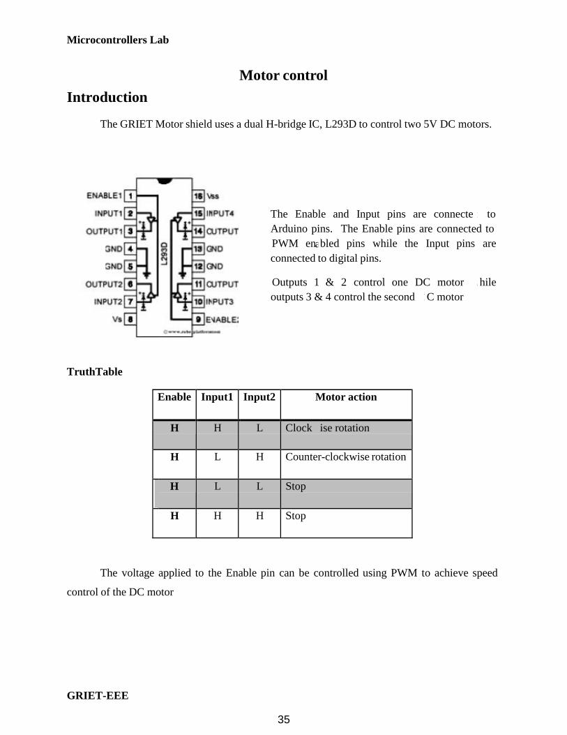
The GRIET Motor shield uses a dual H-bridge IC, L293D to control two 5V DC motors.
The Enable and Input pins are connecte to
Arduino pins. The Enable pins are connected to
PWM en bled pins while the Input pins are
connected to digital pins.
Outputs 1 & 2 control one DC motor hile
TruthTable
outputs 3 & 4 control the second C motor
Enable Input1 Input2 Motor action
H H L Clock ise rotation
H L H Counter-clockwise rotation
H L L Stop
H H H Stop
The voltage applied to the Enable pin can be controlled using PWM to achieve speed
control of the DC motor
35

Microcontrollers Lab
GRIET-EEE
Pin-out
L293D pins Arduino Uno pins ATmega328 pin
IN1 8 PB0
IN2 9 PB1
EN1,2 5 PD5
IN3 10 PB2
IN4 11 PB3
EN3,4 6 PD6
Schematic
Power supply
The power supply for the motor is derived from a DC-DC module. The input for the module can
be 2 AA batteries in series, the output will be 5V. The module can supply up to 300mA of
current.
36

Microcontrollers Lab
GRIET-EEE
Bill of Materials
Part Value Device Package Library Sheet
BAT 2AAPCB 2AAPCB 2AAPCB BHolder 1
DC-DC MAX756MODULE MAX756MODULE MAX756MODULE BHolder 1
IC1 Arduino Shield ARDUINO2009_PIN_22 ARDUINO2009_2 arduino01 1
LED1 1206Red LEDCHIPLED_1206 CHIPLED_1206 led 1
LED2 1206Red LEDCHIPLED_1206 CHIPLED_1206 led 1
R1 330R R-US_R1206 R1206 rcl 1
R2 330R R-US_R1206 R1206 rcl 1
S1 255SB 255SB switch 1
X1 AK500/2 AK500/2 con-
ptr500
1
X2 AK500/2 AK500/2 con-
ptr500
1
Arduino program
void setup()
pinMode(5,OUTPUT);
pinMode(6,OUTPUT);
pinMode(8,OUTPUT);
pinMode(9,OUTPUT);
pinMode(10,OUTPUT);
pinMode(11,OUTPUT);
digitalWrite(5,HIGH);// Make EN1,2 HIGH
digitalWrite (6,HIGH);// Make EN3,4 HIGH
void loop()
// Clockwise rotation
37
Microcontrollers Lab
GRIET-EEE
// Stop
digitalWrite (8,HIGH);
digitalWrite (9,LOW);
delay(3000);
digitalWrite (8,LOW);
digitalWrite (9,LOW);
delay(1000);
// Anti-Clockwise rotation
digitalWrite (8,LOW);
digitalWrite (9,HIGH);
delay(3000);
// Stop
Exercises
digitalWrite (8,LOW);
digitalWrite (9,LOW);
delay(1000);
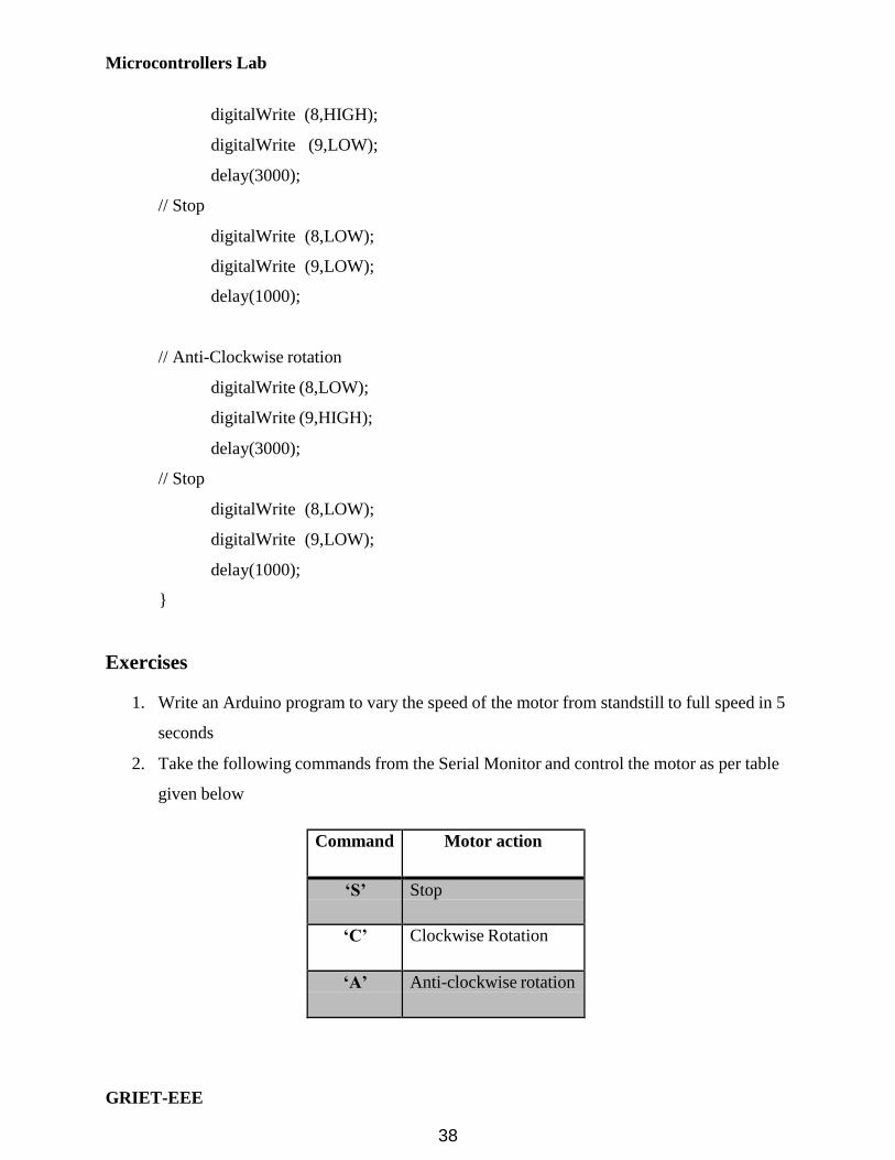
1. Write an Arduino program to vary the speed of the motor from standstill to full speed in 5
seconds
2. Take the following commands from the Serial Monitor and control the motor as per table
given below
Command Motor action
‘S’ Stop
‘C’ Clockwise Rotation
‘A’ Anti-clockwise rotation
38

Microcontrollers Lab
GRIET-EEE
Introduction
Bluetooth
The GRIET BlueTooth shield uses the BlueLink BlueTooth module which has
BlueTooth on one side and serial interface on the other. It has five pins : VCC, GND, TX, RX
and RESET. The TX pin of BlueLink is connected to RX of Arduino and RX connected to TX of
Arduino. Data received on BlueTooth is transferred to Arduino serial port and data sent from the
Arduino serial port is sent over BlueTooth. These data transfers between the Arduino and
BlueLink take place at a baud rate of 9600.
Device discovery & Pairing
Enable BlueTooth on your laptop. Discover the BlueTooth devices in your vicinity.
BlueLink will appear in that list. When you try to connect to BlueLink you will be prompted to
give the passkey. The passkey for BlueLink is 8888. When BlueLink is connected, it will get
mapped as a COM port in the PC. Open the COM port in a terminal program such as
Hyperterminal.
Pin-out
BlueLink pins Arduino Uno pins ATmega328 pin
TX 0(RX) PD0
RX 1(TX) PD1
39

Microcontrollers Lab
GRIET-EEE
B
C
H
U
E
Bill of Materials
Part Value Device Package Library Sheet
LUETOOT MODULE RLBTMODULE RLBTMODULE RLBTMODUL BHolder 1
C1 10uF CPOL-USE2.5-5 E2,5-5 rcl 1
2 1uF C-US 025-025X05 0 C- S025- rcl 1
025 X050
IC1 Arduino Shield ARDUINO2009_PIN_22 ARDUINO2009_2 arduino01 1
Arduino program
void setup()
Serial.begin(9600);
void loop()
Serial.println(“A”);
delay(1000);
40

Microcontrollers Lab
GRIET-EEE
Introduction
ZigBee
The GRIET ZigBee shield allows the Arduino board to communicate wirelessly using
the XBee module. The XBee Series 2 module from Digi has a range of 100 feet indoors and
works at 2.4GHz. For establishing wireless networking using the Series 2 modules, there should
be a ZigBee co-ordinator module and one or more ZigBee router/end-point modules.
The GRIET ZigBee dongle is made the co-ordinator by loading the co-ordinator
firmware in its XBee. Router firmware is loaded in the XBee of the ZigBee shield. X-CTU
software from Digi is used for loading the firmware as well as for setting module parameters.
The Pan ID of both modules should be the same. Note down the SH and SL parameters of the
XBee co-ordinator module and set the DH and DL of the router module equal to SH and SL
respectively.
Pin-out
XBee pins Arduino Uno pins ATmega328 pin
Dout 0(RX) PD0
Din 1(TX) PD1
Schematic
41

Microcontrollers Lab
GRIET-EEE
Bill of Materials
Part Value Device Package Library Sheet
BAT 2AAPCB 2AAPCB 2AAPCB BHolder 1
DC-DC MAX756MODULE MAX756MODULE MAX756MODULE BHolder 1
IC1 Arduino Shield ARDUINO2009_PIN_22 ARDUINO2009_2 arduino01 1
JP1 1x2 Pin Head PINHD-1X2 1X2 pinhead 1
LED1 1206Red LEDCHIPLED_1206 CHIPLED_1206 led 1
R1 330R R-US_R1206 R1206 rcl 1
S1 255SB 255SB switch 1
XBEE XBEE-1B1 XBEE-1B1 XBEE-1 SparkFun 1
Power supply
The ZigBee shield has a DC-DC converter module. 2 AA batteries can provide the input
for the module, the output will be 5V. The module can supply upto 300mA. The 5V of the DC-DC
module is given to the Vin of the Arduino board, so that a battery powered wireless node can be
built. The Xbee is powered by 3.3V supply generated on the Arduino board .
Arduino program
void setup()
Serial.begin(9600);
void loop()
Serial.println(“A”);
delay(1000);
Connect the GRIET ZigBee dongle to your laptop. Load the FTDI drivers and the
dongle will get mapped as a COM port in your laptop. The data transferred from the Arduino
ZigBee shield can be seen in your laptop by using a Terminal program such as Hyperterminal.
You can also use Hyperterminal to transmit data from your laptop via ZigBee to the Arduino.
42

Microcontrollers Lab
GRIET-EEE
Introduction
Real-Time Clock (RTC)
The GRIET RTC shield has the DS1307 RTC chip from Dallas Semiconductor. The
clock/calendar on the chip provides seconds, minutes, hours, day, date, month and year
information. Address and data are transferred serially via a 2-wire bi-directional bus, the I2C
bus. Arduino has a library called Wire.h that handles the details of the I2C protocol. The Wire
library assumes that the SDA and SCL pins of the Arduino (A4 and A5) are used for the I2C
communication. The RTC shield uses these two pins for the interface between Arduino and the
DS1307 RTC chip. The DS1307 uses an external 32.768KHz crystal. The power to the chip is
backed up by an external battery that ensures that the clock keeps running even when the shield
is powered off.
DS1307 registers
Pin-out
DS1307 pins Arduino Uno pins ATmega328 pin
SDA A4 PC4
SCL A5 PD5
43

Microcontrollers Lab
GRIET-EEE
C
D
C
2
2 U
L
0
d
Schematic
Bill of Materials
Part Value Device Package Library Sheet
BAT R2032 CR203 CR 2032 BHol er 1
C1 10uF CPOL-USE2.5-5 E2,5-5 rcl 1
C2 1 uF C-US0 5-025X050 C- S025-025X 050 rcl 1
IC1 Arduino Shield ARDUINO2009_PIN_22 ARDUINO2009_2 arduino01 1
IC2 S1307 DS1307 DI 08 ds1307_pcf8583 1
LED1 1206Red LEDCHIPLED_1206 CHIPLED_1206 led 1
Q1 rystal CRYSTALT C26H TC2 6H crystal 1
R1 10K R-US_R0204/7 0204/7 rcl 1
R2 1 0K R-US_R0204/7 02 4/7 rcl 1
R3 330R R-US_R0204/7 0204/7 rcl 1
44

Microcontrollers Lab
GRIET-EEE
Arduino program
#include "Wire.h"
#define DS1307_I2C_ADDRESS 0x68
// Convert normal decimal numbers to binary coded decimal
byte decToBcd(byte val)
return ( (val/10*16) + (val%10) );
// Convert binary coded decimal to normal decimal numbers
byte bcdToDec(byte val)
return ( (val/16*10) + (val%16) );
// 1) Sets the date and time on the ds1307
// 2) Starts the clock
// 3) Sets hour mode to 24 hour clock
// Assumes you're passing in valid numbers
void setDateDs1307( byte second, // 0-59
byte minute, // 0-59
byte hour, // 1-23
byte dayOfWeek, // 1-7
byte dayOfMonth, // 1-28/29/30/31
byte month, // 1-12
byte year) // 0-99
Wire.beginTransmission(DS1307_I2C_ADDRESS);
Wire.write(0);
Wire.write(decToBcd(second)); // 0 to bit 7 starts the clock
Wire.write(decToBcd(minute));
Wire.write(decToBcd(hour));
45

Microcontrollers Lab
GRIET-EEE
Wire.write(decToBcd(dayOfWeek));
Wire.write(decToBcd(dayOfMonth));
Wire.write(decToBcd(month));
Wire.write(decToBcd(year));
Wire.write(0x10);//sends 0x10 (hex) 00010000 (binary) to control register-turns on
square wave
Wire.endTransmission();
// Gets the date and time from the ds1307
void getDateDs1307( byte *second,
byte *minute,
byte *hour,
byte *dayOfWeek,
byte *dayOfMonth,
byte *month,
byte *year)
// Reset the register pointer
Wire.beginTransmission(DS1307_I2C_ADDRESS);
Wire.write(0);
Wire.endTransmission();
Wire.requestFrom(DS1307_I2C_ADDRESS, 7);
*second = bcdToDec(Wire.read() & 0x7f);
*minute = bcdToDec(Wire.read());
*hour = bcdToDec(Wire.read() & 0x3f); // Need to change this if 12 hour am/pm
*dayOfWeek = bcdToDec(Wire.read());
*dayOfMonth = bcdToDec(Wire.read());
*month = bcdToDec(Wire.read());
*year = bcdToDec(Wire.read());
46

Microcontrollers Lab
GRIET-EEE
void setup()
byte second, minute, hour, dayOfWeek, dayOfMonth, month, year;
Wire.begin();
Serial.begin(9600);
//Change these values to what you want to set your clock to
// You probably only want to set your clock once and then remove
// the setDateDs1307 call.
second = 0;
minute = 02; hour
= 10; dayOfWeek
= 7; dayOfMonth
= 22; month = 5;
year = 12;
setDateDs1307(second, minute, hour, dayOfWeek, dayOfMonth, month, year);
void loop()
byte second, minute, hour, dayOfWeek, dayOfMonth, month, year;
getDateDs1307(&second, &minute, &hour, &dayOfWeek, &dayOfMonth, &month,
&year);
Serial.print(hour, DEC);// convert the byte variable to a decimal number when being
displayed
Serial.print(":");
47

Microcontrollers Lab
GRIET-EEE
if (minute<10)
Serial.print("0");
Serial.print(minute, DEC);
Serial.print(":");
if (second<10)
Serial.print("0");
Serial.print(second, DEC);
Serial.print(" ");
Serial.print(dayOfMonth, DEC);
Serial.print("/");
Serial.print(month, DEC);
Serial.print("/");
Serial.print(year, DEC);
Serial.print(" Day of week:");
switch(dayOfWeek)
case 1:
Serial.println("Sunday");
break;
case 2:
Serial.println("Monday");
break;
case 3:
Serial.println("Tuesday");
break;
case 4:
Serial.println("Wednesday");
break;
48

Microcontrollers Lab
GRIET-EEE
case 5:
Serial.println("Thursday");
break;
case 6:
Serial.println("Friday");
break;
case 7:
Serial.println("Saturday");
break;
//Serial.println(dayOfWeek, DEC);
delay(1000);
void setup()
byte second, minute, hour, dayOfWeek, dayOfMonth, month, year;
Wire.begin();
Serial.begin(9600);
second = 45;
minute = 9;
hour = 10;
dayOfWeek = 1;
dayOfMonth = 2;
month = 12;
year = 12;
//setRTC(second, minute, hour, dayOfWeek, dayOfMonth, month, year);
49

Microcontrollers Lab
GRIET-EEE
void loop()
byte second, minute, hour, dayOfWeek, dayOfMonth, month, year;
getRTC(&second, &minute, &hour, &dayOfWeek, &dayOfMonth,& month, &year);
Serial.print(hour,DEC);
Serial.print(“:”);
Serial.print(minute,DEC);
Serial.print(“:”);
Serial.print(second,DEC);
Serial.print(“ ”);
Serial.print(dayOfMonth,DEC);
Serial.print(“/”);
Serial.print(month,DEC);
Serial.print(“/”);
Serial.print(year,DEC);
Delay(1000);
50

Microcontrollers Lab
GRIET-EEE
Introduction
Color LCD
The Color LCD shield from Sparkfun provides an easy way of interfacing the popular
Nokia6100 graphic color LCD to Arduino. The shield comes with a 132x132 mini color LCD, as
well as a backlight driver circuit. The Nokia 6100 LCD is controlled through a 9-bit SPI(Serial
Peripheral Interface). The Arduino IDE has a ColorLCD library that will help in using the LCD
Pin-out
LCD pins Arduino Uno pins ATmega328 pin
Reset(RES) 8 PB0
Chip Select 9 PB1
Data in/out(DIO) 11 PB3
Serial Clock(SCK) 13 PB5
51

Microcontrollers Lab
GRIET-EEE
Arduino programs
#include <ColorLCDShield.h>
LCDShield lcd;
void setup()
lcd.init(PHILLIPS);
lcd.contrast(40);
lcd.clear(WHITE);
lcd.setStr("Just say no", 2, 20, SLATE, WHITE);
lcd.setStr("to addition", 110, 20, SLATE, WHITE);
lcd.setCircle(66, 66,45, BLUE);
lcd.setCircle(66, 66, 44, BLUE); // Circle in the mid, 54 radius
lcd.setRect(55, 34, 77, 98, 1, BLACK);
lcd.setRect(34, 55, 98, 77, 1, BLACK);
lcd.setLine(27, 27, 105, 105, BLUE);
lcd.setLine(26, 27, 104, 105, BLUE);
lcd.setLine(28, 27, 106, 105, BLUE);
void loop()
The predefined colors are:
BLACK, NAVY, BLUE, TEAL, EMERALD, GREEN, CYAN, SLATE, INDIGO,
TURQUOISE, OLIVE, MAROON, PURPLE, GRAY, SKYBLUE, BROWN, CRIMSON,
ORCHID, RED, MAGENTA, ORANGE, PINK, CORAL, SALMON, ORANGE, GOLD,
YELLOW, WHITE
There are two chipsets:
52

Microcontrollers Lab
GRIET-EEE
EPSON and PHILLIPS. The init function is called with the name of one of the
chipsets(depending on which chipset your shield has).
The Nokia 6100 LCD is a 132x132 pixel screen. The origin (0, 0 point) of the screen is as shown
in the diagram.. There's an x-axis and a y-axis, to pinpoint any of the 17424 pixels. The setCircle function only takes one set of x/y coordinates, and centers a circle of a specified
radius around that point. setLine and setRect both require two sets of x/y coordinates. The line
function draws a straight line from coordinate 0 to coordinate 1, while the setRect draws a box
with opposite corners at the two coordinate pairs.
One final feature of the library allows you to add text to the LCD. There's the setChar function,
which allows you to place one, and only one, character at specified coordinates. Then there's
the setStr function,
which will
place a string of characters on the screen.
When you
use
the setStr or setChar functions, you get to pick two colors: a foreground and background.
53

Microcontrollers Lab
GRIET-EEE
54

Microcontrollers Lab
GRIET-EEE
Introduction
AVR programming
In the Arduino programming we have done till now, we were not required to know
anything about the actual microcontroller on which the Arduino UNO was based. The Arduino
platform was designed so that students with no prior knowledge of microcontrollers could
program and use the boards. Now, we move on to the next stage where we learn about the
microcontroller used in Arduino , its internal resources such as number of ports, internal serial
port, internal ADC and do programming based on the internal registers of the microcontroller.
The Arduino UNO is based on the 8-bit AVR ATmega328 microcontroller. The features of this
microcontroller are:
• 32KB Flash memory
• 1KB EEPROM
• 2KB RAM
• UART
• 6 channel 10 bit ADC
• SPI interface
• I2C interface
• 6 PWM channels
• Two 8-bit timers
• One 16-bit timer
The UNO board works on a 16 MHz external crystal oscillator
55

Microcontrollers Lab
GRIET-EEE
Pin-out of ATmega328
We will be using the Arduino IDE for AVR programming and hence we will still be
using the setup() and loop() functions. The compilation and download process will remain the
same, except that we will now be using the internal registers of the ATmega328 microcontroller
instead of the Arduino functions such as PinMode(), DigitalRead() and DigitalWrite().
Digital I/O
The ATmega328 has three ports: PORTB, PORTC and PORTD. For using the lines of
these ports as general purpose digital I/Os, there are three 8-bit registers associated with each of
these ports:
DDRX: (Data Direction Register)
If a 0 is put in the bit position corresponding to a port line, that port line is made as input.
If a 1 is put in the bit position corresponding to a port line, that port line is made as
output.
PORTX:
If a bit in this register is written logic one, when the pin is configured as an output pin, the port
pin will be drawn high.
56

Microcontrollers Lab
GRIET-EEE
If a bit in this register is written logic zero, when the pin is configured as an output pin,
the port pin will be drawn low.
If a bit in this register is written logic one, when the pin is configured as an input pin,
the internal pull-ups for the port pin are enabled
PINX: The status of the port pins of a port can be read using the PINX register
LEDs and switches Arduino Uno pins ATmega328 pin
LED1 8 PB0
LED2 9 PB1
LED3 10 PB2
LED4 11 PB3
LED5 12 PB4
LED6 13 PB5
S1 2 PD2
S2 3 PD3
S3 4 PD4
S4 5 PD5
S5 6 PD6
S6 7 PD7
57

Microcontrollers Lab
GRIET-EEE
Programs
In the GRIET LED shield, 6 LEDs are connected from PB0 to PB5. For configuring
port B as output and blinking them the code will be:
void setup()
DDRB = 0xff;
PORTB = 0xff;
void loop()
PORTB = ~PORTB;
delay(1000);
1. Program to read the status of switches and control the corresponding LEDs
void setup()
DDRB = 0xff; //making PORTB as output for driving LEDs
PORTB = 0x00;// all LEDs switched off DDRD=0x00;
// making PORTD as input PORTD=0xff; // enabling
the pull-ups for PORTD pins
void loop()
if((PIND & 0x04) == 0) PORTB=0x01;
if((PIND & 0x08) == 0) PORTB=0x02;
if((PIND & 0x10) == 0) PORTB=0x04;
if((PIND & 0x20) == 0) PORTB=0x08;
if((PIND & 0x40) == 0) PORTB=0x10;
if((PIND & 0x80) == 0) PORTB=0x20;
if((PIND==0xff) PORTB=0x00;
58
Microcontrollers Lab
GRIET-EEE
2. Program to set, clear and toggle individual port lines
It will be useful to be able to control individual port lines without affecting the other
lines. For this we define the following macros:
#define setbit(reg,bit) reg = reg|(1<<bit)
#define clearbit(reg,bit) reg=reg&~(1<<bit)
#define togglebit(reg,bit) reg=reg^(1<<bit)
void setup()
DDRB=0xff;//PORTB made as output
PORTB=0x00;//all LEDs off
void loop()
setbit(PORTB,0);
clearbit(PORTB,5);
delay(1000);
clearbit(PORTB,0);
setbit(PORTB,5);
delay(1000);
Excersice
Use the above macros to write code for displaying data on the 2x16 LCD
59

Microcontrollers Lab
GRIET-EEE
Serial Communication
The ATmega328 has an internal USART (Universal Synchronous Asynchronous
Receive/Transmit) for serial transmission. Two pins named RX and TX provide the serial
communication capability to ATmega328. These are alternate functions for the PD0 and PD1
pins respectively.
Initialization
For using the USART for serial communication, the following parameters need to be set:
o Baud Rate
o Enabling receive or transmit or both
o Character width
Setting the baud rate
The baud rate gives the number of bits transmitted/received per second. A 16-bit value called
UBRR0(USART Baud Rate Register) needs to be set for setting the required baud rate.The value
that will be put in UBRR0 will depend on:
o The baud rate required(BAUD)
o The frequency at which the board is working(fosc)
UBRR0 =( fosc/16*BAUD) – 1
This 16 bit value has to be split into two 8 bit registers : UBRR0H and UBRR0L
Procedure for getting the values to be put in UBRR0L and UBRR0H
1.Calculate the UBRR0 for the baud rate required. For the Arduino UNO board, the fosc
frequency is 16MHz
2.Divide the UBRR0 value by 256
3.Put the quotient in UBRR0H
4.Put the remainder in UBRR0L
Sample calculation for 9600 baud
fosc =16000000Hz
BAUD =9600
Substituting these values in the equation, we get
UBRR0=103
Following the procedure for getting the values for UBRRL0 and UBRRH0 we get
UBRR0L=103;
UBRR0H=0;
60

Microcontrollers Lab
GRIET-EEE
Enabling receive, transmit
The above figure gives the bits in the register UCSR0B (USASRT Control & Status Register B)
Bit 3: Transmit Enable
Bit 4: Receive Enable
These two bits should be made 1 in order to enable transmit and receive
The line of code to do this will be:
UCSR0B=0x18;
Setting character width
The above figure gives the bits in the register UCSR0C (USASRT Control & Status Register C)
The UCSZ00 and UCSZ01 bits along with the UCSZ02 in UCSR0B register will be used for
setting the character size as per the table given below
For setting 8-bit character size, the line of code will be
UCSR0C=0x06;
61
Microcontrollers Lab
GRIET-EEE
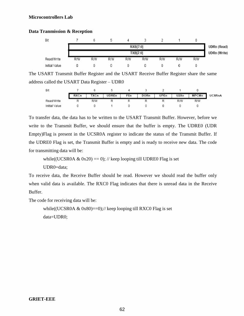
Data Tranmission & Reception
The USART Transmit Buffer Register and the USART Receive Buffer Register share the same
address called the USART Data Register – UDR0
To transfer data, the data has to be written to the USART Transmit Buffer. However, before we
write to the Transmit Buffer, we should ensure that the buffer is empty. The UDRE0 (UDR
Empty)Flag is present in the UCSR0A register to indicate the status of the Transmit Buffer. If
the UDRE0 Flag is set, the Transmit Buffer is empty and is ready to receive new data. The code
for transmitting data will be:
while((UCSR0A & 0x20) == 0); // keep looping till UDRE0 Flag is set
UDR0=data;
To receive data, the Receive Buffer should be read. However we should read the buffer only
when valid data is available. The RXC0 Flag indicates that there is unread data in the Receive
Buffer.
The code for receiving data will be:
while((UCSR0A & 0x80)==0);// keep looping till RXC0 Flag is set
data=UDR0;
62

Microcontrollers Lab
GRIET-EEE
Programs
The program will send a fixed character ‘A’ every second. This can be received in the
Serial Monitor
void setup()
UBRR0L=103;
UBRR0H=0;
UCSR0B=0x18;
UCSR0C=0x06;
void loop()
while((UCSR0A&0x20)==0);
UDR0=’A’;
delay(1000);
The program will receive a character and transmit it back
void setup()
uart_init();
void loop()
unsigned char c;
c=rxchar();
txchar(c);
63

Microcontrollers Lab
GRIET-EEE
void uart_init()
UBRR0L=103;
UBRR0H=0;
UCSR0B=0x18;
UCSR0C=0x06;
void txchar(unsigned char t)
while((UCSR0A&0x20)==0);
UDR0=t;
unsigned char rxchar()
unsigned char r;
while((UCSR0A&0x80)==0);
r = UDR0;
return r;
64

Microcontrollers Lab
GRIET-EEE
Internal ADC
The ATmega328 has a10-bit ADC. The ADC is connected to a 6-channel multiplexer.
For ADC operation, the parameters that need to be considered are:
o ADC voltage reference
o ADC clock
o ADC channel
ADC initialization
The ADC voltage reference can be set by the REFS0 and REFS1 bits in the ADMUX register
The AVcc option is selected by the line of code:
ADMUX = 0x40;
The ADC requires an input clock between 50KHz – 200KHz. The ADC contains a pre-scaler
which generates an acceptable clock frequency. The prescaler bits are to be set in the ADCSRA
register
65

Microcontrollers Lab
GRIET-EEE
The prescaler selections
Since the Arduino UNO operates at 16MHz, a division factor of 128 will generate a clock of
125Khz which is in the acceptable range.
The ADEN bit has to be set for the ADC to be enabled. The line of code for enabling the ADC
and setting a prescaler of 128 will be:
ADCSRA=0x87;
ADC operation
First channel should be selected, before starting conversion. The ADSC bit is set to start the
conversion. After the conversion is over, the ADSC bit becomes zero. The converted value will
be available in ADCH and ADCL. The ADC read code will be:
int adcval;
ADMUX = ADMUX | channel;//where channel can be 0 to 5
ADCSRA = ADCSRA | 0x40;
while((ADCSRA & 0x40)==0);
adcval = (ADCH<<8)|ADCL;
66

Microcontrollers Lab
GRIET-EEE
AVR programs
The program uses the LDR and tempearature sensor(LM35) on the LCD shield, reads the sensor
values and throws the values on the serial port
void setup()
ADMUX=0x40;
ADCSRA=0x87;
Serial.begin(9600);
void loop()
ADMUX=0x44;
Serial.print("Light = ");
Serial.println(adcRead());
delay(1000);
ADMUX=0x45;
Serial.print("Temperature = ");
Serial.println(adcRead()/2);
delay(1000);
int adcRead()
int adcVal;
unsigned char high,low;
ADCSRA=ADCSRA|0x40;
while((ADCSRA&0x40)==0x40);
low=ADCL;
high=ADCH;
adcVal=(high<<8)|low;
return adcVal;
67

Microcontrollers Lab
GRIET-EEE
Interrupts
On a very basic level, an interrupt is an signal that interrupts the current processor
activity. It may be triggered by an external event (change in pin state) or an internal event (a
timer or a software signal). Once triggered, an interrupt pauses the current activity and causes
the program to execute a different function. This function is called an interrupt handler or an
interrupt service routine (ISR). Once the function is completed, the program returns to what it
was doing before the interrupt was triggered.
To illustrate the concept of interrupts let us use a real-world example. Imagine you’re
sitting on your couch, enjoying a nice hot coffee and watching a movie after a long day. Life is
good. There’s only one problem: you’re waiting for an incredibly important package to arrive,
and you need it as soon as possible. If you were a normal AVR program or Arduino sketch,
you’d have to repeatedly stop your movie, get up, and go check the mailbox every 5 minutes to
make sure you knew when the package was there.
Instead, imagine if the package was sent by courier with delivery confirmation. Now, the
delivery man will go to your front door and ring the doorbell as soon as he arrives. That’s your
interrupt trigger. Once you get the trigger, you can pause your movie and go deal with the
package. That’s your interrupt service routine. As soon as you’re done, you can pick up the film
where you left off, with no extra time wasted. That’s the power of interrupts.
The AVR chips used in most Arduinos are not capable of parallel processing, i.e. they
can’t do multiple things at once. Using asynchronous processing via interrupts enables us to
maximize the efficiency of our code, so we don’t waste any precious clock cycles on polling
loops or waiting for things to occur. Interrupts are also good for applications that require precise
timing, because we know we’ll catch our event the moment it occurs, and won’t accidentally
miss anything.
68
Microcontrollers Lab
GRIET-EEE
Every AVR processor has a list of interrupt sources, or vectors, which include the type of events
that can trigger an interrupt. When interrupts are enabled and one of these events occur, the code
will jump to a specific location in program memory – the interrupt vector.
By writing an ISR and then placing a link to it at the interrupt vector’s memory location,
we can tell our code to do something specific when an interrupt is triggered. In order to
successfully use an interrupt, we’ll need to do three things:
1. Set the AVR’s Global Enable Interrupts bit in Status Register
2. Set the interrupt enable bit for our specific interrupt vector (each vector has it’s own
on/off switch)
3. Write an ISR and attach it to our target interrupt vector
Starting with the first step, we’ll include the interrupt library from avr-libc, then use an avr-
libc function to set our global interrupt enable bit. Next, we need to enable the interrupt we
want. Most 8-bit AVR’s like the ATMega328 have 2 hardware interrupts, INT0 and INT1. If
you’re using a standard Arduino board, these are tied to digital pins 2 and 3, respectively. Let’s
enable INT0 so we can detect an input change on pin 2 from a button or switch. We can use our
LEDs and switches shield for this purpose.
AVR program #include <avr/interrupt.h>
void setup(void)
pinMode(2, INPUT); digitalWrite(2, HIGH); // Enable pullup resistor
sei(); // Enable global interrupts
EIMSK |= (1 << INT0); // Enable external interrupt INT0
EICRA |= (1 << ISC01); // Trigger INT0 on falling edge
void loop(void)
69

Microcontrollers Lab
GRIET-EEE
// Interrupt Service Routine attached to INT0 vector
ISR(EXT_INT0_vect)
digitalWrite(13, !digitalRead(13));// Toggle LED on pin 13
70

Microcontrollers Lab
GRIET-EEE
Timers
You’re probably familiar with the general concept of a timer: something used to measure
a given time interval. In microcontrollers, the idea is the same. You can set a timer to trigger an
interrupt at a certain point in the future. When that point arrives, you can use the interrupt as an
alert, run different code, or change a pin output. Think of it as an alarm clock for your processor.
The beauty of timers is that just like external interrupts, they run asynchronously, or
independently from your main program. Rather than running a loop or repeatedly calling millis(),
you can let a timer do that work for you while your code does other things.
For example, say you’re building a security robot. As it roams the halls, you want it to
blink an LED every two seconds to let potential intruders know they’ll be vaporized if they make
a wrong move. Using normal code techniques, you’d have to set a variable with the next time the
LED should blink, then check constantly to see if that time had arrived. With a timer interrupt,
you can set up the interrupt, then turn on the timer. Your LED will blink perfectly on cue, even
while your main program executes its complicated terminateVillian() routine.
Timers work by incrementing a counter variable, also known as a counter register. The
counter register can count to a certain value, depending on its size. The timer increments this
counter one step at a time until it reaches its maximum value, at which point the counter
overflows, and resets back to zero. The timer normally sets a flag bit to let you know an overflow
has occurred. You can check this flag manually, or you can also have the timer trigger an
interrupt as soon as the flag is set. Like any other interrupt, you can specify an Interrupt Service
Routine (ISR) to run code of your choice when the timer overflows. The ISR will reset the
overflow flag behind the scenes, so using interrupts is usually your best option for simplicity and
speed.
In order to increment the counter value at regular intervals, the timer must have access to a clock
source. The clock source generates a consistent repeating signal. Every time the timer detects
this signal, it increases its counter by one.
71
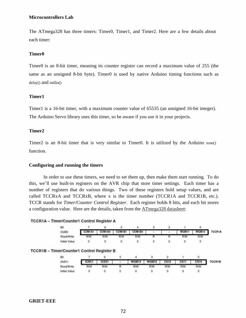
Microcontrollers Lab
GRIET-EEE
The ATmega328 has three timers: Timer0, Timer1, and Timer2. Here are a few details about
each timer:
Timer0
Timer0 is an 8-bit timer, meaning its counter register can record a maximum value of 255 (the
same as an unsigned 8-bit byte). Timer0 is used by native Arduino timing functions such as
delay() and millis()
Timer1
Timer1 is a 16-bit timer, with a maximum counter value of 65535 (an unsigned 16-bit integer).
The Arduino Servo library uses this timer, so be aware if you use it in your projects.
Timer2
Timer2 is an 8-bit timer that is very similar to Timer0. It is utilized by the Arduino tone()
function. Configuring and running the timers
In order to use these timers, we need to set them up, then make them start running. To do
this, we’ll use built-in registers on the AVR chip that store timer settings. Each timer has a
number of registers that do various things. Two of these registers hold setup values, and are
called TCCRxA and TCCRxB, where x is the timer number (TCCR1A and TCCR1B, etc.).
TCCR stands for Timer/Counter Control Register. Each register holds 8 bits, and each bit stores
a configuration value. Here are the details, taken from the ATmega328 datasheet:
72

Microcontrollers Lab
GRIET-EEE
To start using our timer, the most important settings are the last three bits in TCCR1B,
CS12, CS11, and CS10. These dictate the timer clock setting. By setting these bits in various
combinations, we can tell the timer to run at different speeds. Here’s the relevant table from the
datasheet:
By default, these bits are set to zero. Let’s use a simple example, and say that we want to
have Timer1 run at clock speed, with one count per clock cycle. The pre-scaler is set to 1024.
Since the Arduino runs at 16Mhz, this pre-scaler setting gives a clock of 16000000/1024, a timer
resolution of 0.000064secs. The number of such counts that will occur in 1 second will be
1/0.000064 = 15625counts. AVR micros support a mode called CTC,Clear Timer On Compare
Match where the timer gets reset when the cont matches a preset value loaded in a register and
an interrupt is generated. This is the mode we will be using in our example to get a timing of 1
second.
73

Microcontrollers Lab
GRIET-EEE
AVR Program
// Arduino timer CTC interrupt example
#include<avr/io.h>
#include<avr/interrupt.h>
#define LEDPIN 13
void setup()
pinMode(LEDPIN, OUTPUT);
// initialize Timer1
cli(); // disable global interrupts
TCCR1A = 0; // set entire TCCR1A register to 0
TCCR1B = 0; // same for TCCR1B
// set compare match register to desired timer count:
OCR1A = 15625;
// turn on CTC mode:
TCCR1B |= (1 << WGM12);
// Set CS10 and CS12 bits for 1024 prescaler:
TCCR1B |= (1 << CS10);
TCCR1B |= (1 << CS12);
// enable timer compare interrupt:
TIMSK1 |= (1 << OCIE1A);
// enable global interrupts:
sei();
void loop()
ISR(TIMER1_COMPA_vect)
digitalWrite(LEDPIN, !digitalRead(LEDPIN));
74

Microcontrollers Lab
Use this space for writing Exercise Programs

Microcontrollers Lab
Use this space for writing Exercise Programs

Microcontrollers Lab
Use this space for writing Exercise Programs

Microcontrollers Lab
Use this space for writing Exercise Programs

Microcontrollers Lab
Use this space for writing Exercise Programs

Microcontrollers Lab
Use this space for writing Exercise Programs

Microcontrollers Lab
Use this space for writing Exercise Programs

Microcontrollers Lab
Use this space for writing Exercise Programs

Microcontrollers Lab
Use this space for writing Exercise Programs

Microcontrollers Lab
Use this space for writing Exercise Programs