department of electrical & electronics engineering files/iv-i hvdct cf.pdfdepartment of...
TRANSCRIPT

Department of Electrical & Electronics Engineering
Course Title: ______HVDC Transmission___________
Following documents are available in Course File.
S.No. Points Yes No
1 Institute and Department Vision and Mission Statements √
2 PEO & PO Mapping √
3 Academic Calendar √
4 Subject Allocation Sheet √
5 Class Time Table, Individual Timetable (Single Sheet) √
6 Syllabus Copy √
7 Course Handout √
8 CO-PO Mapping √
9 CO-Cognitive Level Mapping √
10 Lecture Notes √
11 Tutorial Sheets With Solution √
12 Soft Copy of Notes/Ppt/Slides √
13 Sessional Question Paper and Scheme of Evaluation √
14 Best, Average and Weak Answer Scripts for Each Sessional Exam. (Photocopies)
√
15 Assignment Questions and Solutions √
16 Previous University Question Papers √
17 Result Analysis √
18 Feedback From Students √
19 Course Exit Survey √
20 CO Attainment for All Mids. √
21 Remedial Action. √
Course Instructor / Course Coordinator Course Instructor / Course Coordinator
(Name) (Signature)

Department of Electrical & Electronics Engineering
Department/Program-EEE
VISION OF THE INSTITUTE:
To be among the best of the institutions for engineers and technologists with attitudes, skills and knowledge and to become an epicenter of creative solutions. MISSION OF THE INSTITUTE:
To achieve and impart quality education with an emphasis on practical skills and social relevance.
MISSION OF THE PROGRAM:
• To become an internationally leading department for higher learning.
• To build upon the culture and values of universal science and contemporary education. • To be a center of research and education generating knowledge and technologies which lay
groundwork in shaping the future in the fields of electrical and electronics engineering.
• To develop partnership with industrial, R&D and government agencies and actively participate in conferences, technical and community activities.

Department of Electrical & Electronics Engineering
Programme Educational Objectives (B.Tech. – EEE)
This programme is meant to prepare our students to professionally thrive and to lead. During their
progression:
Graduates will be able to
PEO 1: Have a successful technical or professional careers, including supportive and leadership roles on
multidisciplinary teams.
PEO 2: Acquire, use and develop skills as required for effective professional practices.
PEO 3: Able to attain holistic education that is an essential prerequisite for being a responsible member
of society.
PEO 4: Engage in life-long learning, to remain abreast in their profession and be leaders in our
technologically vibrant society.
Programme Outcomes (B.Tech. – EEE)
At the end of the Programme, a graduate will have the ability to
PO 1: Apply knowledge of mathematics, science, and engineering. PO 2: Design and conduct experiments, as well as to analyze and interpret data. PO 3: Design a system, component, or process to meet desired needs within realistic
constraints such as economic, environmental, social, political, ethical, health and safety, manufacturability, and sustainability.
PO 4: Function on multi-disciplinary teams. PO 5: Identify, formulates, and solves engineering problems. PO 6: Understanding of professional and ethical responsibility. PO 7: Communicate effectively. PO 8: Broad education necessary to understand the impact of engineering solutions in a global,
economic, environmental, and societal context. PO 9: Recognition of the need for, and an ability to engage in life-long learning. PO 10: Knowledge of contemporary issues. PO 11: Utilize experimental, statistical and computational methods and tools necessary for
engineering practice. PO 12: Demonstrate an ability to design electrical and electronic circuits, power electronics,
power systems; electrical machines analyze and interpret data and also an ability to design digital and analog systems and programming them.
PEOs & POs Mapping
Programme Educational Objectives (PEOs)
Programme Outcomes (POs) 1 2 3 4 5 6 7 8 9 10 11 12
1 M M - - H - - H H - H H 2 - - M M H H H - - - - H 3 - - - - H H M M M M H H 4 - - - M M H M H H - M H
* H: Strongly Correlating (3); M: Moderately Correlating (2)& L: Weakly Correlating (1)

Department of Electrical & Electronics Engineering
ACADEMIC CALENDAR
Academic Year 2018-19
S. No. EVENT PERIOD DURATION
1 1st Spell of Instructions 02-07-2018 to 01-09-2018 9 Weeks
2 1st Mid-term Examinations 03-09-2018 to 05-09-2018 3 Days 3 2nd Spell of Instructions 06-09-2018 to 24-10-2018 7 Weeks
4 2nd Mid-term Examinations 25-10-2018 to 27-10-2018 3 Days
5 Preparation 29-10-2018 to 06-11-2018 1 Week 3 Days
6 End Semester Examinations (Theory/
Practicals) Regular/Supplementary 08-11-2018 to 08-12-2018 4 Weeks 3 Days
7 Commencement of Second Semester, A.Y 2018-19
10-12-2018
Dean of Academic Affairs

Department of Electrical & Electronics Engineering
SUBJECT ALLOCATION SHEET
II YEAR( GR17) Section-A Section-B
Special Functions and Complex Variable Dr GS Dr GS
Electromagnetic Fields SN SN
Network Theory MS MS
DC Machines and Transformers Dr BPB Dr BPB
Computer Organization PRK PRK
DC Machines Lab MP/DSR PRK/DSR
Electrical Networks Lab YSV/GBR YSV/GBR
Electrical Simulation Lab GSR/PS GSR/PS
Environmental Science
III YEAR (GR15) Section-A Section-B
Power Transmission System VVRR/MP VVRR/MP
Microcontrollers PK PK
Power Electronics Dr TSK DKK
Electrical Measurements& Instrumentation (PE-1) UVL UVL
Solar & Wind Energy Systems (OE-1) PSVD/Dr JP PSVD/Dr JP
Sensors/Measurements& Instrumentation Lab PSVD/PS UVL/PS
Power Electronics Lab PPK/MRE SN/MRE
Microcontrollers Lab RAK/DKK PK/DKK
IV YEAR(GR15) Section-A Section-B
Power Semiconductor Drives YSV Dr DGP
Power System Operation & Control Dr JSD Dr JSD
High Voltage DC Transmission Systems MRE Dr SVJK
Electrical Distribution Systems (PE-3) VVSM
High Voltage Engineering (PE-3) VUR
Soft Computing Techniques (OE-3) RAK RAK
DSP based Electrical Lab AVK/DKK AVK/DKK
Power Systems Simulation Lab VVSM / GSR VVSM /
GSR
Power Electronic Drives Lab MP/GBR MP/GBR
I/I BEE(AICTE) A/B C/D/E
BEE ML
BEE KS
BEE MK
BEE MVK
BEE MNSR
Civil II/I (GR15) A B
ET PPK PPK

Department of Electrical & Electronics Engineering
AY: 2018-2019
TIME TABLE
GRIET/PRIN/06/G/01/18-19
wef: 02 July 2018
B.Tech - EEE - A
IV Year - I Semester
Day/Hour 10:00-10:50
10:50-11:40
11:40-12:30
12:30-1:00
1:00-1:45
1:45-2:30
2:30-3:15 3:15-4:00
Room No.
MONDAY HVDCT PSD PSD
BR
EA
K
PSS Lab / DSP Lab A1 /A2
Theory 4502
TUESDAY SCT SCT EDS/HV
E PED Lab / PSS Lab
A1 /A2 Lab
DSP Lab-4508 PSS Lab- 4504 PED Lab- 4407
WEDNESDAY EDS/HVE SCT SCT DSP Lab / PED Lab
A1 /A2
THURSDAY EDS/HVE PSOC PSOC PSD PSD HVDCT HVDCT
FRIDAY HVDCT HVDC
T EDS/HV
E PSOC PSOC SCT SCT
Class Incharge:
P Praveen Kumar
SATURDAY HVDCT EDS/H
VE EDS/HV
E PSOC PSOC PSD PSD
Subject Code Subject Name Faculty Code
Faculty name Almanac
GR15A4022 Power Semiconductor Drives YSV Y Satya Vani 1st Spell of Instructions 02-07-2018 to
01-09-2018
GR15A4023 Power System Operation &
Control Dr JSD Dr J Sridevi 1st Mid-term Examinations
03-09-2018 to 05-09-2018
GR15A4024 High Voltage DC Transmission
Systems MRE M Rekha 2nd Spell of Instructions
06-09-2018 to
24-10-2018
GR15A4026 Electrical Distribution Systems VVSM VVS Madhuri 2nd Mid-term Examinations 25-10-2018 to
27-10-2018
GR15A4147 High Voltage Engineering VUR V Usharani Preparation
29-10-2018 to
06-11-2018
GR15A4148 Soft Computing Techniques
(OE-3)
RAK R Anil Kumar End Semester Examinations (Theory/ Practicals) Regular / Supplementary
08-11-2018 to
08-12-2018
GR15A4027 DSP based Electrical Lab AVK/DK
K A Vinay Kumar / D Karuna Kumar
Commencement of Second Semester, A.Y
10/12/2018
GR15A4028 Power Systems Simulation Lab GSR/VV
SM G Sandhya Rani/ VVS Madhuri
GR15A4029 Power Electronic Drives Lab MP/GBR M Prashanth/ G Bhaskar Rao
HOD Co-ordinator DAA

Department of Electrical & Electronics Engineering
DEPARTMENT OF ELECTRICAL AND ELECTRONICS ENGINEERING
GRIET/PRIN/06/G/01/18-19
wef: 02 July 2018
B.Tech - EEE - B
IV Year - I Semester
Day/Hour 10:00-10:50
10:50-11:40
11:40-12:30
12:30-1:00
1:00-1:45
1:45-2:30
2:30-3:15 3:15-4:00
Room No.
MONDAY SCT SCT PSOC
BR
EA
K
HVDCT HVDCT PSD PSD
Theory 4512
TUESDAY PSD PSD EDS/HV
E SCT SCT PSD PSD
Lab DSP Lab-4508 PSS Lab- 4504 PED Lab- 4407
WEDNESDAY EDS/HVE HVDC
T HVDCT PSOC PSOC SCT SCT
THURSDAY EDS/HVE HVDC
T HVDCT
PSS Lab / DSP Lab B1 /B2
FRIDAY
PSOC PSOC EDS/HV
E DSP Lab / PED Lab
B1 /B2
Class Incharge:
P Praveen Kumar
SATURDAY PSOC EDS/H
VE EDS/HV
E PED Lab / PSS Lab
B1 /B2
Subject Code Subject Name Faculty Code
Faculty name Almanac
GR15A4022 Power Semiconductor Drives Dr DGP Dr D G Padhan 1st Spell of Instructions 02-07-2018 to
01-09-2018
GR15A4023 Power System Operation &
Control Dr JSD Dr J Sridevi 1st Mid-term Examinations
03-09-2018 to
05-09-2018
GR15A4024 High Voltage DC Transmission
Systems Dr SVJK Dr S V Jayaram Kumar 2nd Spell of Instructions
06-09-2018 to
24-10-2018
GR15A4026 Electrical Distribution Systems
(PE) VVSM VVS Madhuri 2nd Mid-term Examinations
25-10-2018 to
27-10-2018
GR15A4147 High Voltage Engineering (PE) VUR V Usharani Preparation
29-10-2018 to
06-11-2018
GR15A4148 Soft Computing Techniques
(OE-3) RAK R Anil Kumar End Semester Examinations
(Theory/ Practicals) Regular / Supplementary
08-11-2018 to
08-12-2018 GR15A4027 DSP based Electrical Lab
AVK/DKK
A Vinay Kumar / D Karuna Kumar
GR15A4028 Power Systems Simulation Lab GSR/VV
SM G Sandhya Rani/ VVS Madhuri
Commencement of Second Semester, A.Y
10/12/2018
GR15A4029 Power Electronic Drives Lab MP/GBR M Prashanth/ G Bhaskar Rao
HOD Co-ordinator DAA
Department of Electrical & Electronics Engineering
Syllabus – HVDC TRANSMISSION
UNIT-I
HVDC TRANSMISSION: Introduction, equipment required for HVDC systems, Comparison of AC
and DC Transmission, Limitations of HVDC transmission lines, reliability of HVDC systems,
comparison of HVDC link with EHVAC link, HVDC convertors, HVDC –VSC transmission System:
VSC system components, Control of Active and reactive power, Applications of VSC systems.
UNIT-II
HVDC CONVERTER OPERATION AND ANALYSIS: Thyristors and their characteristics, silicon
rectifier, 6 pulse convertor configuration, ideal communication process without gate control, DC
output voltage , gate control of valves, analysis of voltage wave forms with overlap angle, analysis of
communication circuits , equivalent circuit of rectifier, Inverter operation with overlap, Equivalent
circuit of inverter , complete equivalent circuit of HVDC link, power factor and reactive power of
converters
UNIT-III
HVDC CONVERTER CONTROL :AC transmission and its control , necessary of dc link control,
rectifier control , inverter control , constant beta control, constant gamma control, compounding of
rectifiers, current compounding of inverter , complete HVDC system characteristics , power reversal
in DC link, voltage dependent current order limit(VDCOL), system control hierarchy ,individual
phase control, cosine control of phase delay, linear control phase delay , equidistance pulse control,
pulse frequency control , constant current control
UNIT-IV
HARMONICS IN HVDC SYSTEM: Harmonics due to converter , characteristic current harmonics
in the 12 pulse converter , harmonic model and equivalent circuit ,design of AC filters , single tune
and double tuned high pass filters , second order filters and C-Type filter, Reactive power
considerations of AC filters
UNIT-V
FAULTS ON AC SIDE OF CONVERTER STATION: 3-phase symmetrical fault and asymmetrical
faults, commutation failure, DC circuit breaker, Ground Electrodes for HVDC system: Advantage and
problems with ground return, HVDC system grounding , Resistance of electrodes- Electric current
field, resistance of electrodes in uniform earth and non-uniform earth,distribution of current field
between electrodes.
TEXT BOOKS:
1. HVDC transmission by S Kamakshaiah and V Kamaraju, Tata McGraw Hills Publications.
REFERENCE BOOKS:
1. K.R.Padiyar., HVDC Power Transmission System(English) 2nd edition. 2. Arillaga., High
Voltage Direct Transmission,(London)Peter Peregrinus, 1981.

Department of Electrical & Electronics Engineering
GUIDELINES TO STUDY THE COURSE/SUBJECT
Academic Year : 2018-2019
Semester : I
Name of the Program:….EEE…… B.Tech……………..… Section:A/B
Course/Subject: …… HVDC……………… Code…GR15A4024……
Name of the Faculty: Dr.S.V.JAYARAM KUMAR,
M.REKHA Dept.: ……EEE…………
Designation: Professor, Asst.Professor
Guidelines to study the Course/ Subject: HVDC TRANSMISSION
Course Design and Delivery System (CDD):
• The Course syllabus is written into number of learning objectives and outcomes.
• These learning objectives and outcomes will be achieved through lectures, assessments, assignments, experiments in the laboratory, projects, seminars, presentations, etc.
• Every student will be given an assessment plan, criteria for assessment, scheme
of evaluation and grading method. • The Learning Process will be carried out through assessments of Knowledge,
Skills and Attitude by various methods and the students will be given guidance to refer to the text books, reference books, journals, etc.
The faculty be able to –
• Understand the principles of Learning • Understand the psychology of students • Develop instructional objectives for a given topic • Prepare course, unit and lesson plans • Understand different methods of teaching and learning • Use appropriate teaching and learning aids • Plan and deliver lectures effectively
• Provide feedback to students using various methods of Assessments and
tools of Evaluation • Act as a guide, advisor, counselor, facilitator, motivator and not just as a teacher alone
Signature of HOD Signature of faculty
Date: Date:

Department of Electrical & Electronics Engineering
COURSE SCHEDULE
Academic Year : 2018-2019
Semester : I
Name of the Program:……EEE…… B.Tech……...… Section:A/B
Course/Subject: …HVDC TRANSMISSION……… ..Code:…GR15A4024………
Name of the Faculty: Dr.S.V.JAYARAM KUMAR
M.REKHA
Designation: Professor, Professor, Asst.Professor
The Schedule for the whole Course / Subject is:
UNIT Description
Total No. of
periods
1. HVDC TRANSMISSION
10
HVDC CONVERTER OPERATION AND
ANALYSIS.
8
2.
HVDC CONVERTER CONTROL
8
3.
HARMONICS IN HVDC SYSTEM:
8
4.
FAULTS ON AC SIDE OF CONVERTER
STATION.
10
5.
Total No. of Instructional periods available for the course: ….42…….Hours / Periods

Department of Electrical & Electronics Engineering
SCHEDULE OF INSTRUCTIONS
COURSEPLAN
Academic Year : 2018-2019
Semester : I
Name of the program :……EEE…… B.Tech….…… Section: A/B
Course/Subject: ……HVDC TRANSMISSION Code:…GR15A4024 Dept: EEE
TEXT BOOKS:
1. HVDC transmission by S Kamakshaiah and V Kamaraju, Tata McGraw Hills Publications.
REFERENCE BOOKS:
1. K.R.Padiyar., HVDC Power Transmission System(English) 2nd edition. 2. Arillaga., High
Voltage Direct Transmission,(London)Peter Peregrinus, 1981.
No. of Objectives & References
Unit Lesson Periods Topics / Sub-Topics Outcomes (Text Book,
No. No.
Nos.
Journal…)
Page Nos.: ____to ____
1 1. 1
Introduction 1&1 T1:1
1 2. 1
Equipment required for HVDC systems 1&1 T1:13
1 3. 1
Comparison of AC and DC Transmission 1&1 T1:17
1 4. 1
Limitations of HVDC transmission lines 1&1 T1:28
1 5. 1
Reliability of HVDC systems 1&1 T1:28
1 6 1
comparison of HVDC link with EHVAC link
T1:31 1&2
1 7. 1
HVDC convertors, HVDC –VSC transmission 1&2 T1:31
1 8. 1
System: VSC system components 2&2 T1:31
1 9. 1
Control of Active and reactive
power, Applications of VSC systems 2&3 T1:34
2 10 2
Thyristors and their characteristics 2&3
T1:40
2 11. 1
Silicon rectifiers IGBT’s ,HVDC
voltage source converters principle
and operation 2&3 T1:42
Department of Electrical & Electronics Engineering
2 12. 1
6 pulse convertor configuration, ideal
communication process without gate control 3&1
T1:62
2 13. 1 DC output voltage , gate control of valves
3&2
T1:71
2 15. 1 analysis of voltage wave forms with overlap angle, analysis of communication circuits 3&3
T1:81
2 16. 1
equivalent circuit of rectifier, Inverter
operation with overlap 3&2
T1:94
2 17. 1 Equivalent circuit of inverter , complete equivalent circuit of HVDC link 1&3
T1:94
2 18. 1
power factor and reactive power of converters, analysis of 12 pulse converter 1&3
T1:97
2 19. 1 power flow in HVDC links, Power flow and current control , power loss in DC systems 1&3
T1:103
2 20 1
operation and analysis of VSC converters, VSC inverter operation , power flow in VSC-DC transmission 1&3
T1:106
2 21 2 comparison between CSC(classical HVDC) and NSC-HVDC system 2&3
T1:112
3 22 2 AC transmission and its control , necessary of dc link control, 2&3
T1:129
3 23 1 rectifier control , inverter control , constant beta control 2&3
T1:131
3 24 1 constant gamma control, compounding of rectifiers, current compounding of inverter 3&4
T1:134
3 25 1
complete HVDC system characteristics , power reversal in DC link, voltage dependent current order limit(VDCOL) 3&4
T1:135
3 26
system control hierarchy ,individual phase control, cosine control of phase delay, linear control phase delay
3 & 4
T1:142
3 27
2
equidistance pulse control, pulse frequency control , constant current control, inverter exhibition angle control 4&5
T1:147
3 28
2 Constant power control, control system for HVDC converter, inverter operation problem, control of VSC converters. 4&5
T1:152
4 29 2
Harmonics due to converter , characteristic current harmonics in the 12 pulse converter , 4&4 T1:174

Department of Electrical & Electronics Engineering
4 30 1
harmonics in VSC converter , harmonic model and equivalent circuit 4&5 T1:177
4 31 2
design of AC filters , single tuned and double tuned high pass filters , second order filters and C-Type filter 5&5 T1:200
4
32
1
Reactive power considerations of AC filters
, Active filters and their applications, filters
with VSC-HVDC schemes
5&5 T1:210
5
33
2
3-phase symmetrical fault and asymmetrical
faults, commutation failure, DC circuit
breaker
6&5
T1:263
5
34
3
Multi Terminal HVDC system: series and
parallel MTDC systems and their operation
and control, AC-DC system interaction short
circuit rates and its effects
7&5 T1:306
Signature of
HOD Signature of faculty
Department of Electrical & Electronics Engineering
SCHEDULE OF INSTRUCTIONS
UNIT PLAN
Academic Year : 2018-2019
Semester : II UNIT NO.: ………I………….
Name of the Program: B.Tech ……..…Electrical……..… Year: ……IV………. Section: A&B
Course/Subject: …HVDC Transmission Course Code: ..GR15A4024.
Name of the Faculty: …Dr.S.V.Jayaram Kumar, M.Rekha………….Dept.: …EEE………
Designation: PROFESSOR, ASST.PROFESSOR
No. of Objectives & References Unit Lesson Periods Topics / Sub-Topics Outcomes (Text Book, No. No.
Nos. Journal…)
Page Nos.: ____to ____
1 1. 1
Introduction 1&1 1: Pg.No1
1 2. 1 Equipment required for HVDC systems 1&1 1: Pg.No.13
1 3. 1 Comparison of AC and DC Transmission 1&1 1: Pg.No17
1 4. 1 Limitations of HVDC transmission lines 1&1 1: Pg.No28
1 5. 1
Reliability of HVDC systems 1&1 1: Pg.No28
1 6 1 comparison of HVDC link with EHVAC link
1: Pg.No31 1&2
1 7. 1 HVDC convertors, HVDC –VSC transmission 1&2 1: Pg.No31
1 8. 1
System: VSC system components 2&2 1: Pg.No131

Department of Electrical & Electronics Engineering
SCHEDULE OF INSTRUCTIONS
UNIT PLAN
Academic Year : 2018-2019
Semester : II UNIT NO.: ………II………….
Name of the Program: B.Tech ……..…Electrical……..… Year: ……IV………. Section: A&B
Course/Subject: …HVDC Transmission Course Code: .. GR15A4024.
Name of the Faculty: …Dr.S.V.Jayaram Kumar, M.Rekha………….Dept.: …EEE………
Designation: PROFESSOR, ASST.PROFESSOR
Unit No
Lesson No
Periods Topics/Subtopics Objectives &Outcome Nos
(Text Book,Jouranal…) Page No.s
2 9 2 Choice Of Converter Configuration 1,2 2.Pg.no: 43-46
2 10
2 Analysis Of 6 pulse Graetz Circuit 1,2 1.Pg no. 84-97
2.Pg.no.46-61
2 11 2 Analysis Of 6 pulse Graetz Circuit 1,2
1.Pg no. 84-97
2.Pg.no.46-61 2 12 2 Analysis Of 6 pulse Graetz Circuit 1,2 1.Pg no. 84-97
2.Pg.no.46-61 2 13 2 Analysis Of 12 pulse Graetz Circuit 1,2 2.Pg.no.61-65
2 14 2
Principle Of DC link Control
1,2,3 2,3,4
1.Pg no. 66-68
2.Pg.no.76-79
2 15 2 Converter Control Characteristics 1,2,3 2,3,4
1.Pg no. 68-75
2.Pg.no.79-84
2 1
6 2 Converter Control Characteristics 1,2,3
2,3,4
1.Pg no. 68-75
2.Pg.no.79-84
2 17 2 Firing Angle Control 1,2,3 2,3,4
1.Pg no. 341-
346
2.Pg.no.84-89 2 18 2 Current and extinction angle control 1,2,3
2,3,4
1.Pg no.346-
350
2.Pg.no.8-90 2 19 2 Effect Of Source Inductance on the
system,starting and stopping of DC
link
1,2,3 2,3,4
2.Pg.no.90-94

Department of Electrical & Electronics Engineering
SCHEDULE OF INSTRUCTIONS
UNIT PLAN
Academic Year : 2018-2019
Semester : II UNIT NO.: ………III………….
Name of the Program: B.Tech ……..…Electrical……..… Year: ……IV………. Section: A&B
Course/Subject: …HVDC Transmission Course Code: .. GR15A4024.
Name of the Faculty: …Dr.S.V.Jayaram Kumar, M.Rekha………….Dept.: …EEE………
Designation: PROFESSOR, ASST.PROFESSOR
Unit No
Lesson No
Periods
Topics/Subtopics Objectives &Outcome Nos
(Text Book,Jouranal…) Page No.s
3 20 2 AC transmission and its control , necessary of dc link control,
2&3 1: Pg.no.129
3 21 2 AC transmission and its control , necessary of dc link control,
2&3 1: Pg.no.129
3 22 2 rectifier control , inverter control , constant beta control
2&3 1: Pg.no.131
3 23 2 constant gamma control, compounding of rectifiers, current compounding of inverter
3&4 1: Pg.no.134
3
24
2 complete HVDC system characteristics , power reversal in DC link, voltage dependent current order limit(VDCOL)
3&4 1: Pg.no.135
3
25
2 system control hierarchy ,individual phase control, cosine control of phase delay, linear control phase delay
3&4 1: Pg.no.135
3
26 2
equidistance pulse control, pulse frequency control , constant current control, inverter exhibition angle control 4&5
1: Pg.no.147
3 27
2
Constant power control, control system for HVDC converter, inverter operation problem, control of VSC converters. 4&5
1:Pg.no.152

Department of Electrical & Electronics Engineering
SCHEDULE OF INSTRUCTIONS
UNIT PLAN
Academic Year : 2018-2019
Semester : II UNIT NO.: ………IV………….
Name of the Program: B.Tech ……..…Electrical……..… Year: ……IV………. Section: A&B
Course/Subject: …HVDC Transmission Course Code: .. GR15A4024.
Name of the Faculty: …Dr.S.V.Jayaram Kumar, M.Rekha………….Dept.: …EEE………
Designation: Professor, Asst.Professor
Unit No
Lesson
No Period
s Topics/Subtopics
Objectives &Outcome Nos
(Text Book,Jouranal…)
Page No.s
4 28 2
Harmonics due to converter , characteristic current harmonics in the 12 pulse converter , 3&4
1:Pg.No.17
4
4 29 1
harmonics in VSC converter , harmonic model and equivalent circuit 3&5 1: Pg.No 177
4 30 2
design of AC filters , single tuned and double tuned high pass filters , second order filters and C-Type filter 3&5
1: Pg.No
200
4
31
1
Reactive power considerations of AC filters
,Active filters and their applications, filters
with VSC-HVDC schemes
3&5
1: Pg.No
210

Department of Electrical & Electronics Engineering
SCHEDULE OF INSTRUCTIONS
UNIT PLAN
Academic Year : 2018-2019
Semester : II UNIT NO.: ………V………….
Name of the Program: B.Tech ……..…Electrical……..… Year: ……IV………. Section: A&B
Course/Subject: …HVDC Transmission Course Code: .. GR15A4024.
Name of the Faculty: …Dr.S.V.Jayaram Kumar, M.Rekha………….Dept.: …EEE………
Designation: PROFESSOR, ASST.PROFESSOR
Unit
No
Lesson
No
Periods Topics/Subtopics Objectiv
es
&Outco
me Nos
(Text Book,Jouran
al…) Page No.s
5
32
2
3-phase symmetrical fault and
asymmetrical faults, commutation
failure, DC circuit breaker
3&5
1:Pg.No263
5
33
2
Multi Terminal HVDC system: series
and parallel MTDC systems and their
operation and control, AC-DC system
interaction short circuit rates and its
effects
2&5
1:Pg.No306
5
34
2
3-phase symmetrical fault and
asymmetrical faults, commutation
failure, DC circuit breaker
3&5
1:Pg.No.263
5
35
2
Multi Terminal HVDC system: series
and parallel MTDC systems and their
operation and control, AC-DC system
interaction short circuit rates and its
effects
2&5
1:Pg No306

Department of Electrical & Electronics Engineering
LESSON PLAN
Academic Year : 2018-19
Semester : I
Name of the Program: B.Tech IV Year: ……………….. Section:A&B
Course/Subject: HVDC Transmission Course Code: GR15A4024
Name of the Faculty: DR.S.V.JAYARAM KUMAR,
M.REKHA Dept.: EEE
Designation: Professor, Assistant professor.
Lesson No: 1 Duration of Lesson: 1hr 30 Minutes
Lesson Title: Types of DC links
INSTRUCTIONAL/LESSON OBJECTIVES:
On completion of this lesson the student shall be able to:
1. To deal with the importance of HVDC Transmission and HVDC Converters
2. To deal with power conversion between Ac to DC and DC to AC.
TEACHING AIDS : PPTs, White Board, LCD Projector, Marker
TEACHING POINTS :
• 5 min.: Taking attendance
• 10 min.: Re collecting the contents of previous class.
• 70 min.: Explain in detail about DC Links.
• 5 min.: Doubts clarification and Review of the class.
Assignment / Questions: Explain briefly about different types of HVDC links. (Obj:1,2/Out:1,2)
Signature of faculty

Department of Electrical & Electronics Engineering
LESSON PLAN
Academic Year : 2018-19
Semester : I
Name of the Program: B.Tech IV Year: ……………….. Section:A&B
Course/Subject: HVDC Transmission Course Code: GR15A4024
Name of the Faculty: Dr.S.V.Jayaram Kumar,
M.Rekha Dept.: EEE
Designation: Professor, Assistant professor..
Lesson No: 2 Duration of Lesson: 1hr 30 Minutes
Lesson Title: Apparatus required for HVDC systems
INSTRUCTIONAL/LESSON OBJECTIVES:
On completion of this lesson the student shall be able to:
1. To deal with the importance of HVDC Transmission and HVDC Converters
2. To deal with power conversion between Ac to DC and DC to AC.
TEACHING AIDS : PPTs, White Board, LCD Projector, Marker
TEACHING POINTS :
• 5 min.: Taking attendance
• 10 min.: Re collecting the contents of previous class.
• 70 min.: Explain in detail about the apparatus required for HVDC systems.
• 5 min.: Doubts clarification and Review of the class.
Assignment / Questions: Draw a schematic diagram of typical HVDC converter station and describe the various components of the station. (Obj:1,2/Out:1,2)
Signature of faculty

Department of Electrical & Electronics Engineering
LESSON PLAN
Academic Year : 2018-19
Semester : I
Name of the Program: B.Tech IV Year: ……………….. Section:A&B
Course/Subject: HVDC Transmission Course Code: GR15A4024
Name of the Faculty: DR.S.V.JAYARAM
KUMAR, M.REKHA Dept.: EEE
Designation Professor, Assistant professor.
Lesson No: 3 Duration of Lesson: 1hr 30 Minutes
Lesson Title: Comparison of AC and DC Transmission
INSTRUCTIONAL/LESSON OBJECTIVES:
On completion of this lesson the student shall be able to:
1. To deal with the importance of HVDC Transmission and HVDC Converters
2. To deal with power conversion between Ac to DC and DC to AC.
TEACHING AIDS : PPTs, White Board, LCD Projector, Marker
TEACHING POINTS :
• 5 min.: Taking attendance
• 10 min.: Re collecting the contents of previous class.
• 70 min.: Explain in detail about comparision of AC and DC Transmission.
• 5 min.: Doubts clarification and Review of the class.
Assignment / Questions: What is the need for interconnection of systems? Explain the merits of connecting HVAC systems by HVDC tie -lines (Obj:1,2/Out:1,2)
Signature of faculty

Department of Electrical & Electronics Engineering
LESSON PLAN
Academic Year : 2018-19
Semester : I
Name of the Program: B.Tech IV Year: ……………….. Section: A& B
Course/Subject: HVDC Transmission Course Code: GR15A4024
Name of the Faculty: DR.S.V.JAYARAM KUMAR,
M.REKHA Dept.: EEE
Designation: Professor, Assistant Professor.
Lesson No: 4 Duration of Lesson: 1hr 30 Minutes
Lesson Title: Applications of DC Transmission System
INSTRUCTIONAL/LESSON OBJECTIVES:
On completion of this lesson the student shall be able to:
1. To deal with the importance of HVDC Transmission and HVDC Converters
2. To deal with power conversion between Ac to DC and DC to AC.
TEACHING AIDS : PPTs, White Board, LCD Projector, Marker
TEACHING POINTS :
• 5 min.: Taking attendance
• 10 min.: Re collecting the contents of previous class.
• 70 min.: Explain in detail about the applications of HVDC systems.
• 5 min.: Doubts clarification and Review of the class.
Assignment / Questions: Explain the economic advantages of HVDC system. (Obj:1,2/Out:1,2)
Signature of faculty

Department of Electrical & Electronics Engineering
LESSON PLAN
Academic Year : 2018-19
Semester : I
Name of the Program: B.Tech IV Year: ……………….. Section: A&B
Course/Subject: HVDC Transmission Course Code: GR15A4024
Name of the Faculty: DR.S.V.JAYARAM KUMAR,
M.REKHA Dept.: EEE
Designation: Professor, Assistant professor..
Lesson No: 5 Duration of Lesson: 1hr 30 Minutes
Lesson Title: Choice of Converter Configuration
INSTRUCTIONAL/LESSON OBJECTIVES:
On completion of this lesson the student shall be able to:
1. To deal with the importance of HVDC Transmission and HVDC Converters
2. To deal with power conversion between Ac to DC and DC to AC.
TEACHING AIDS : PPTs, White Board, LCD Projector, Marker
TEACHING POINTS :
• 5 min.: Taking attendance
• 10 min.: Re collecting the contents of previous class.
• 70 min.: Explain in detail about Choice of Converter Configuration.
• 5 min.: Doubts clarification and Review of the class.
Assignment / Questions: What are the factors which help in deciding the number of pulse converters used
in a systems. Classify them as economic, technical and describe. (Obj: 1, 2/Out: 1, 2)
Signature of faculty

Department of Electrical & Electronics Engineering
LESSON PLAN
Academic Year : 2018-19
Semester : I
Name of the Program: B.Tech IV Year: ……………….. Section:A&B
Course/Subject: HVDC Transmission Course Code: GR15A4024
Name of the Faculty: DR.S.V.JAYARAM KUMAR,
M.REKHA Dept.: EEE
Designation: Professor, Assistant professor..
Lesson No: 6 Duration of Lesson: 1hr 30 Minutes
Lesson Title: Analysis of 6 pulse Graetz Circuit
INSTRUCTIONAL/LESSON OBJECTIVES:
On completion of this lesson the student shall be able to:
1. To deal with the importance of HVDC Transmission and HVDC Converters
2. To deal with power conversion between Ac to DC and DC to AC.
TEACHING AIDS : PPTs, White Board, LCD Projector, Marker
TEACHING POINTS :
• 5 min.: Taking attendance
• 10 min.: Re collecting the contents of previous class.
• 70 min.: Explain in detail about Analysis of 6 pulse Graetz Circuit.
• 5 min.: Doubts clarification and Review of the class.
Assignment / Questions: Obtain expression for the output voltage and direct current of a converter
working as a rectifier with delay angle `α' and commutation angle `γ'. (Obj:1,2/Out:1,2)
Signature of faculty
Department of Electrical & Electronics Engineering
LESSON PLAN
Academic Year : 2018-19
Semester : I
Name of the Program: B.Tech IV Year: ……………….. Section: A&B
Course/Subject: HVDC Transmission Course Code: GR15A4024
Name of the Faculty: DR.S.V.JAYARAM KUMAR,
M.REKHA Dept.: EEE
Designation: Professor, Assistant professor.
Lesson No: 7 Duration of Lesson: 1hr 30 Minutes
Lesson Title: Analysis of 6 pulse Graetz Circuit
INSTRUCTIONAL/LESSON OBJECTIVES:
On completion of this lesson the student shall be able to:
1. To deal with the importance of HVDC Transmission and HVDC Converters
2. To deal with power conversion between Ac to DC and DC to AC.
TEACHING AIDS : PPTs, White Board, LCD Projector, Marker
TEACHING POINTS :
• 5 min.: Taking attendance
• 10 min.: Re collecting the contents of previous class.
• 70 min.: Explain in detail about Analysis of 6 pulse Graetz Circuit.
• 5 min.: Doubts clarification and Review of the class.
Assignment / Questions: With the help of neat sketches, analyze a six pulse rectifier bridge circuit
with an overlap angle greater than 600. Deduce the relevant equations and draw the necessary graphs.
(Obj:1,2/Out:1,2)
Signature of faculty

Department of Electrical & Electronics Engineering
LESSON PLAN
Academic Year : 2018-19
Semester : I
Name of the Program: B.Tech IV Year: ……………….. Section:A&B
Course/Subject: HVDC Transmission Course Code: GR15A4024
Name of the Faculty: DR.S.V.JAYARAM KUMAR,
M.REKHA Dept.: EEE
Designation: Professor, Assistant professor.
Lesson No: 8 Duration of Lesson: 1hr 30 Minutes
Lesson Title: Analysis of 6 pulse Graetz Circuit
INSTRUCTIONAL/LESSON OBJECTIVES:
On completion of this lesson the student shall be able to:
1. To deal with the importance of HVDC Transmission and HVDC Converters
2. To deal with power conversion between Ac to DC and DC to AC.
TEACHING AIDS : PPTs, White Board, LCD Projector, Marker
TEACHING POINTS :
• 5 min.: Taking attendance
• 10 min.: Re collecting the contents of previous class.
• 70 min.: Explain in detail about Analysis of 6 pulse Graetz Circuit.
• 5 min.: Doubts clarification and Review of the class.
Assignment / Questions: Sketch a timing diagram for a 3phase Graetz's circuit considering with and
without overlap angle less than 600. (Obj:1,2/Out:1,2)
Signature of faculty

Department of Electrical & Electronics Engineering
LESSON PLAN
Academic Year : 2018-19
Semester : I
Name of the Program: B.Tech IV Year: ……………….. Section:
A&B
Course/Subject: HVDC Transmission Course Code: GR15A4024
Name of the Faculty: DR.S.V.JAYARAM KUMAR,
M.REKHA Dept.: EEE
Designation: Professor, Assistant professor.
Lesson No: 9 Duration of Lesson: 1hr 30 Minutes
Lesson Title: Analysis of 12 pulse Graetz Circuit
INSTRUCTIONAL/LESSON OBJECTIVES:
On completion of this lesson the student shall be able to:
1. To deal with the importance of HVDC Transmission and HVDC Converters
2. To deal with power conversion between Ac to DC and DC to AC.
TEACHING AIDS : PPTs, White Board, LCD Projector, Marker
TEACHING POINTS :
• 5 min.: Taking attendance
• 10 min.: Re collecting the contents of previous class.
• 70 min.: Explain in detail about Analysis of 12 pulse Graetz Circuit.
• 5 min.: Doubts clarification and Review of the class.
Assignment / Questions: What is the reason for using star-star and star-delta transformer configurations for
12 pulse converter. Derive an equation for primary current using fourier analysis. (Obj:1,2/Out:1,2)
Signature of faculty

Department of Electrical & Electronics Engineering
LESSON PLAN
Academic Year : 2018-19
Semester : I
Name of the Program: B.Tech IV Year: ……………….. Section:A& B
Course/Subject: HVDC Transmission Course Code: GR15A4024
Name of the Faculty: DR.S.V.JAYARAM KUMAR,
M.REKHA Dept.: EEE
Designation: Professor, Assistant professor.
Lesson No: 10 Duration of Lesson: 1hr 30 Minutes
Lesson Title: Principle of DC link Control
INSTRUCTIONAL/LESSON OBJECTIVES:
On completion of this lesson the student shall be able to:
1. To deal with the importance of HVDC Transmission and HVDC Converters
2. To deal with power conversion between Ac to DC and DC to AC.
3. To deal with firing angle of HVDC System
TEACHING AIDS : PPTs, White Board, LCD Projector, Marker
TEACHING POINTS :
• 5 min.: Taking attendance
• 10 min.: Re collecting the contents of previous class.
• 70 min.: Explain in detail about Principle of DC link Control.
• 5 min.: Doubts clarification and Review of the class.
Assignment / Questions: Derive the mathematical model of d.c. link controllers of a d.c. link. (Obj:1,2,3/Out:2,3,4)
Signature of faculty

Department of Electrical & Electronics Engineering
LESSON PLAN
Academic Year : 2018-19
Semester : I
Name of the Program: B.Tech IV Year: ……………….. Section:A&B
Course/Subject: HVDC Transmission Course Code: GR15A4024
Name of the Faculty: DR.S.V.JAYARAM KUMAR,
M.REKHA Dept.: EEE
Designation: Professor, Assistant professor.
Lesson No: 11 Duration of Lesson: 1hr 30 Minutes
Lesson Title: Converter control characteristics
INSTRUCTIONAL/LESSON OBJECTIVES:
On completion of this lesson the student shall be able to:
1. To deal with the importance of HVDC Transmission and HVDC Converters
2. To deal with power conversion between Ac to DC and DC to AC.
3. To deal with firing angle of HVDC System
TEACHING AIDS : PPTs, White Board, LCD Projector, Marker
TEACHING POINTS :
• 5 min.: Taking attendance
• 10 min.: Re collecting the contents of previous class.
• 70 min.: Explain in detail about Converter control characteristics.
• 5 min.: Doubts clarification and Review of the class.
Assignment / Questions: What are the basic characteristics of converter control? With the aid of V-I characteristics, explain how power ow control is achieved? (Obj:1,2,3/Out:2,3,4)
Signature of faculty

Department of Electrical & Electronics Engineering
LESSON PLAN
Academic Year : 2018-19
Semester : I
Name of the Program: B.Tech IV Year: ……………….. Section:A&B
Course/Subject: HVDC Transmission Course Code: GR15A4024
Name of the Faculty: DR.S.V.JAYARAM KUMAR,
M.REKHA Dept.: EEE
Designation: Professor, Assistant professor.
Lesson No: 12 Duration of Lesson: 1hr 30 Minutes
Lesson Title: Converter control characteristics
INSTRUCTIONAL/LESSON OBJECTIVES:
On completion of this lesson the student shall be able to:
1. To deal with the importance of HVDC Transmission and HVDC Converters
2. To deal with power conversion between Ac to DC and DC to AC.
3. To deal with firing angle of HVDC System
TEACHING AIDS : PPTs, White Board, LCD Projector, Marker
TEACHING POINTS :
• 5 min.: Taking attendance
• 10 min.: Re collecting the contents of previous class.
• 70 min.: Explain in detail about Principle of Converter control characteristics.
• 5 min.: Doubts clarification and Review of the class.
Assignment / Questions: What are the desired features of control? Explain in detail. (Obj:1,2,3/Out:2,3,4)
Signature of faculty

Department of Electrical & Electronics Engineering
LESSON PLAN
Academic Year : 2018-19
Semester : I
Name of the Program: B.Tech IV Year: ……………….. Section:A&B
Course/Subject: HVDC Transmission Course Code: GR15A4024
Name of the Faculty: DR.S.V.JAYARAM KUMAR,
M.REKHA Dept.: EEE
Designation: Professor, Assistant professor.
Lesson No: 13 Duration of Lesson: 1hr 30 Minutes
Lesson Title: Firing angle control
INSTRUCTIONAL/LESSON OBJECTIVES:
On completion of this lesson the student shall be able to:
1. To deal with the importance of HVDC Transmission and HVDC Converters
2. To deal with power conversion between Ac to DC and DC to AC.
3. To deal with firing angle of HVDC System
TEACHING AIDS : PPTs, White Board, LCD Projector, Marker
TEACHING POINTS :
• 5 min.: Taking attendance
• 10 min.: Re collecting the contents of previous class.
• 70 min.: Explain in detail about Firing angle control.
• 5 min.: Doubts clarification and Review of the class.
Assignment / Questions: What is equivalent pulse control? What are the advantages of equivalent pulse contur over individual phase control? (Obj:1,2,3/Out:2,3,4)
Signature of faculty

Department of Electrical & Electronics Engineering
LESSON PLAN
Academic Year : 2018-19
Semester : I
Name of the Program: B.Tech IV Year: ……………….. Section:A&B
Course/Subject: HVDC Transmission Course Code: GR15A4024
Name of the Faculty: DR.S.V.JAYARAM KUMAR,
M.REKHA Dept.: EEE
Designation: Professor, Assistant professor.
Lesson No: 14 Duration of Lesson: 1hr 30 Minutes
Lesson Title: Current and extinction angle control
INSTRUCTIONAL/LESSON OBJECTIVES:
On completion of this lesson the student shall be able to:
1. To deal with the importance of HVDC Transmission and HVDC Converters
2. To deal with power conversion between Ac to DC and DC to AC.
3. To deal with firing angle of HVDC System
TEACHING AIDS : PPTs, White Board, LCD Projector, Marker
TEACHING POINTS :
• 5 min.: Taking attendance
• 10 min.: Re collecting the contents of previous class.
• 70 min.: Explain in detail about Current and extinction angle control.
• 5 min.: Doubts clarification and Review of the class.
Assignment / Questions: What is the necessity of having constant ignition angle, constant current and constant extinction angle controllers at each converter station? (Obj:1,2,3/Out:2,3,4)
Signature of faculty

Department of Electrical & Electronics Engineering
LESSON PLAN
Academic Year : 2018-19
Semester : I
Name of the Program: B.Tech IV Year: ……………….. Section:A&B
Course/Subject: HVDC Transmission Course Code: GR15A4024
Name of the Faculty: DR.S.V.JAYARAM KUMAR, M.REKHA
Dept.: EEE Designation: Professor, Assistant professor..
Lesson No: 15 Duration of Lesson: 1hr 30 Minutes
Lesson Title: Effect of source inductance on the system, Starting and stopping of DC link
INSTRUCTIONAL/LESSON OBJECTIVES:
On completion of this lesson the student shall be able to:
1. To deal with the importance of HVDC Transmission and HVDC Converters
2. To deal with power conversion between Ac to DC and DC to AC.
3. To deal with firing angle of HVDC System
TEACHING AIDS : PPTs, White Board, LCD Projector, Marker
TEACHING POINTS :
• 5 min.: Taking attendance
• 10 min.: Re collecting the contents of previous class.
• 70 min.: Explain in detail about Effect of source inductance on the system, Starting and
•
stopping of DC link.
5 min.: Doubts clarification and Review of the class.
Assignment / Questions: Explain the working of working basic power controller using VDCOL (Voltage Dependent Current Order Limiter). (Obj:1,2,3/Out:2,3,4)
Signature of faculty

Department of Electrical & Electronics Engineering
LESSON PLAN
Academic Year : 2018-19
Semester : I
Name of the Program: B.Tech IV Year: ……………….. Section:A&B
Course/Subject: HVDC Transmission Course Code: GR15A4024
Name of the Faculty: DR.S.V.JAYARAM KUMAR, M.REKHA
Dept.: EEE Designation: Professor, Assistant professor.
Lesson No: 16 Duration of Lesson: 1hr 30 Minutes
Lesson Title: Reactive power requirements in steady state, Conventional Control Strategies
INSTRUCTIONAL/LESSON OBJECTIVES:
On completion of this lesson the student shall be able to:
1. To deal with firing angle of HVDC System.
2. To deal with Reactive power control of HVDC system
TEACHING AIDS : PPTs, White Board, LCD Projector, Marker
TEACHING POINTS :
• 5 min.: Taking attendance
• 10 min.: Re collecting the contents of previous class.
• 70 min.: Explain in detail about Reactive power requirements in steady state, Conventional
•
Control Strategies.
5 min.: Doubts clarification and Review of the class.
Assignment / Questions: What is meant by Reactive power control and also give different sources of reactive power. (Obj:3,4/Out:4,5)
Signature of faculty

Department of Electrical & Electronics Engineering
LESSON PLAN
Academic Year : 2018-19
Semester : I
Name of the Program: B.Tech IV Year: ……………….. Section:A&B
Course/Subject: HVDC Transmission Course Code: GR15A4024
Name of the Faculty: DR.S.V.JAYARAM KUMAR,
M.REKHA Dept.: EEE
Designation: Professor, Assistant professor.
Lesson No: 17 Duration of Lesson: 1hr 30 Minutes
Lesson Title: Alternate Control Strategies
INSTRUCTIONAL/LESSON OBJECTIVES:
On completion of this lesson the student shall be able to:
1. To deal with firing angle of HVDC System.
2. To deal with Reactive power control of HVDC system
TEACHING AIDS : PPTs, White Board, LCD Projector, Marker
TEACHING POINTS :
• 5 min.: Taking attendance
• 10 min.: Re collecting the contents of previous class.
• 70 min.: Explain in detail about Alternate Control Strategies
• 5 min.: Doubts clarification and Review of the class.
Assignment / Questions: Write a note on Alternate control strategies. (Obj:3,4/Out:4,5)
Signature of faculty

Department of Electrical & Electronics Engineering
LESSON PLAN
Academic Year : 2018-19
Semester : I
Name of the Program: B.Tech IV Year: ……………….. Section:A&B
Course/Subject: HVDC Transmission Course Code: GR15A4024
Name of the Faculty: DR.S.V.JAYARAM KUMAR,
M.REKHA Dept.: EEE
Designation: Professor, Assistant professor..
Lesson No: 18 Duration of Lesson: 1hr 30 Minutes
Lesson Title: Sources of Reactive power
INSTRUCTIONAL/LESSON OBJECTIVES:
On completion of this lesson the student shall be able to:
1. To deal with firing angle of HVDC System.
2. To deal with Reactive power control of HVDC system
TEACHING AIDS : PPTs, White Board, LCD Projector, Marker
TEACHING POINTS :
• 5 min.: Taking attendance
• 10 min.: Re collecting the contents of previous class.
• 70 min.: Explain in detail about Sources of Reactive power
• 5 min.: Doubts clarification and Review of the class.
Assignment / Questions: Give different sources of reactive power. (Obj:3,4/Out:4,5)
Signature of faculty

Department of Electrical & Electronics Engineering
LESSON PLAN
Academic Year : 2018-19
Semester : I
Name of the Program: B.Tech IV Year: ……………….. Section:A&B
Course/Subject: HVDC Transmission Course Code: GR15A4024
Name of the Faculty: DR.S.V.JAYARAM KUMAR,
M.REKHA Dept.: EEE
Designation: Professor, Assistant professor.
Lesson No: 19 Duration of Lesson: 1hr 30 Minutes
Lesson Title: Modelling of DC link
INSTRUCTIONAL/LESSON OBJECTIVES:
On completion of this lesson the student shall be able to:
1. To deal with firing angle of HVDC System.
2. To deal with Reactive power control of HVDC system
TEACHING AIDS : PPTs, White Board, LCD Projector, Marker
TEACHING POINTS :
• 5 min.: Taking attendance
• 10 min.: Re collecting the contents of previous class.
• 70 min.: Explain in detail about Modelling of DC link.
• 5 min.: Doubts clarification and Review of the class.
Assignment / Questions: Explain by means of a schematic diagram and with theortical expression, how power ow through HVDC link, is controlled? (Obj:3,4/Out:4,5)
Signature of faculty

Department of Electrical & Electronics Engineering
LESSON PLAN
Academic Year : 2018-19
Semester : I
Name of the Program: B.Tech IV Year: ……………….. Section:A&B
Course/Subject: HVDC Transmission Course Code: GR15A4024
Name of the Faculty: DR.S.V.JAYARAM KUMAR,
M.REKHA Dept.: EEE
Designation: Professor, Assistant professor.
Lesson No: 20 Duration of Lesson: 1hr 30 Minutes
Lesson Title: P.U system for d.c quantities
INSTRUCTIONAL/LESSON OBJECTIVES:
On completion of this lesson the student shall be able to:
1. To deal with firing angle of HVDC System.
2. To deal with Reactive power control of HVDC system
TEACHING AIDS : PPTs, White Board, LCD Projector, Marker
TEACHING POINTS :
• 5 min.: Taking attendance
• 10 min.: Re collecting the contents of previous class.
• 70 min.: Explain in detail about P.U system for d.c quantities.
• 5 min.: Doubts clarification and Review of the class.
Assignment / Questions: Write a short notes on:
(a) Modeling of H.V.D.C. links
(b) P.U. system for d.c. quantities. (Obj:3,4/Out:4,5)
Signature of faculty

Department of Electrical & Electronics Engineering
LESSON PLAN
Academic Year : 2018-19
Semester : I
Name of the Program: B.Tech IV Year: ……………….. Section:A&B
Course/Subject: HVDC Transmission Course Code: GR15A4024
Name of the Faculty: DR.S.V.JAYARAM KUMAR,
M.REKHA Dept.: EEE
Designation: Professor, Assistant professor.
Lesson No: 21 Duration of Lesson: 1hr 30 Minutes
Lesson Title: Solution of AC- DC load flow
INSTRUCTIONAL/LESSON OBJECTIVES:
On completion of this lesson the student shall be able to:
1. To deal with firing angle of HVDC System.
2. To deal with Reactive power control of HVDC system
TEACHING AIDS : PPTs, White Board, LCD Projector, Marker
TEACHING POINTS :
• 5 min.: Taking attendance
• 10 min.: Re collecting the contents of previous class.
• 70 min.: Explain in detail about Solution of AC- DC load flow.
• 5 min.: Doubts clarification and Review of the class.
Assignment / Questions: What do you understand by a load flow? Is the load flow chart different for a DC Load flow as compared to AC load flow? (Obj:3,4/Out:4,5)
Signature of faculty

Department of Electrical & Electronics Engineering
LESSON PLAN
Academic Year : 2018-19
Semester : I
Name of the Program: B.Tech IV Year: ……………….. Section:A&B
Course/Subject: HVDC Transmission Course Code: GR15A4024
Name of the Faculty: DR.S.V.JAYARAM
KUMAR, M.REKHA Dept.: EEE
Designation: Professor, Assistant professor.
Lesson No: 22 Duration of Lesson: 1hr 30 Minutes
Lesson Title: Protection against over current and overvoltage in converter station
INSTRUCTIONAL/LESSON OBJECTIVES:
On completion of this lesson the student shall be able to:
1. To deal with the protection of HVDC system
TEACHING AIDS : White Board, Marker
TEACHING POINTS :
• 5 min.: Taking attendance
• 10 min.: Re collecting the contents of previous class.
• 70 min.: Explain in detail about Protection against over current and overvoltage in converter
•
station.
5 min.: Doubts clarification and Review of the class.
Assignment / Questions: What are the basic principles of over current protection. (Obj:6/Out:7)
Signature of faculty
Department of Electrical & Electronics Engineering
LESSON PLAN
Academic Year : 2018-19
Semester : I
Name of the Program: B.Tech IV Year: ……………….. Section:A&B
Course/Subject: HVDC Transmission Course Code: GR15A4024
Name of the Faculty: DR.S.V.JAYARAM
KUMAR, M.REKHA Dept.: EEE
Designation: Professor, Assistant professor.
Lesson No: 23 Duration of Lesson: 1hr 30 Minutes
Lesson Title: Surge arrestors, Smoothing Reactors
INSTRUCTIONAL/LESSON OBJECTIVES:
On completion of this lesson the student shall be able to:
1. To deal with the protection of HVDC system
TEACHING AIDS : White Board, Marker
TEACHING POINTS :
• 5 min.: Taking attendance
• 10 min.: Re collecting the contents of previous class.
• 70 min.: Explain in detail about Surge arrestors, Smoothing Reactors.
• 5 min.: Doubts clarification and Review of the class.
Assignment / Questions: Give the necessity of smoothing reactor in a HVDC system and list out main functions of it. (Obj:6/Out:7)
Signature of faculty
Department of Electrical & Electronics Engineering
LESSON PLAN
Academic Year : 2018-19
Semester : I
Name of the Program: B.Tech IV Year: ……………….. Section:A&B
Course/Subject: HVDC Transmission Course Code: GR15A4024
Name of the Faculty: DR.S.V.JAYARAM
KUMAR, M.REKHA Dept.: EEE
Designation: Professor, Assistant professor.
Lesson No: 24 Duration of Lesson: 1hr 30 Minutes
Lesson Title: DC Breakers, Corona effects on DC lines
INSTRUCTIONAL/LESSON OBJECTIVES:
On completion of this lesson the student shall be able to:
1. To deal with the protection of HVDC system
TEACHING AIDS : White Board, Marker
TEACHING POINTS :
• 5 min.: Taking attendance
• 10 min.: Re collecting the contents of previous class.
• 70 min.: Explain in detail about DC Breakers, Corona effects on DC lines
• 5 min.: Doubts clarification and Review of the class.
Assignment / Questions: How is the effect of corona neglected in a HVDC system? Compare this with corona effect of a HVDC system. (Obj:6/Out:7)
Signature of faculty

Department of Electrical & Electronics Engineering
LESSON PLAN
Academic Year : 2018-19
Semester : I
Name of the Program: B.Tech IV Year: ……………….. Section:A&B
Course/Subject: HVDC Transmission Course Code: GR15A4024
Name of the Faculty:
DR.S.V.JAYARAM KUMAR,
M.REKHA Dept.: EEE
Designation: Professor,
Assistant professor.
PROFESSOR. Lesson No: 25 Duration of Lesson: 1hr 30 Minutes
Lesson Title: Generation of Harmonics, Characteristic harmonics
INSTRUCTIONAL/LESSON OBJECTIVES:
On completion of this lesson the student shall be able to:
1. To deal with Power factor improvement of HVDC system
TEACHING AIDS : White Board, Marker
TEACHING POINTS :
• 5 min.: Taking attendance
• 10 min.: Re collecting the contents of previous class.
• 70 min.: Explain in detail about Generation of Harmonics, Characteristic harmonics
• 5 min.: Doubts clarification and Review of the class.
Assignment / Questions: Why are harmonics generated in HVDC converter and what are the problems as-sociated with the harmonics. Suggest some remedial measures. (Obj:5/Out:6, 7)
Signature of faculty

Department of Electrical & Electronics Engineering
LESSON PLAN
Academic Year : 2018-19
Semester : I
Name of the Program: B.Tech IV Year : ……………….. Section:A&B
Course/Subject: HVDC Transmission Course Code: GR15A4024
Name of the Faculty: DR.S.V.JAYARAM
KUMAR, M.REKHA Dept.: EEE
Designation: Professor, Assistant professor..
Lesson No: 26 Duration of Lesson: 1hr 30 Minutes
Lesson Title: Calculation of AC Harmonics, Non Characteristics harmonics
INSTRUCTIONAL/LESSON OBJECTIVES:
On completion of this lesson the student shall be able to:
1. To deal with Power factor improvement of HVDC system
TEACHING AIDS : White Board, Marker
TEACHING POINTS :
• 5 min.: Taking attendance
• 10 min.: Re collecting the contents of previous class.
• 70 min.: Explain in detail about Calculation of AC Harmonics, Non Characteristics harmonics
• 5 min.: Doubts clarification and Review of the class.
Assignment / Questions: How is Total Harmonic Distortion estimated in a circuit? Explain the relevance of THD to a HVDC system. (Obj:5/Out:6, 7)
Signature of faculty
Department of Electrical & Electronics Engineering
LESSON PLAN
Academic Year : 2018-19
Semester : I
Name of the Program: B.Tech IV Year: ……………….. Section:A&B
Course/Subject: HVDC Transmission Course Code: GR15A4024
Name of the Faculty: DR.S.V.JAYARAM KUMAR,
M.REKHA Dept.: EEE
Designation: Professor, Assistant professor.
Lesson No: 27 Duration of Lesson: 1hr 30 Minutes
Lesson Title: Types of AC filters
INSTRUCTIONAL/LESSON OBJECTIVES:
On completion of this lesson the student shall be able to:
1. To deal with Power factor improvement of HVDC system
TEACHING AIDS : White Board, Marker
TEACHING POINTS :
• 5 min.: Taking attendance
• 10 min.: Re collecting the contents of previous class.
• 70 min.: Explain in detail about Types of AC filters
• 5 min.: Doubts clarification and Review of the class.
Assignment / Questions: What are the various types of _lters that are employed in HVDC converter station? Discuss them in detail. (Obj:5/Out:6, 7)
Signature of faculty

Department of Electrical & Electronics Engineering
LESSON PLAN
Academic Year : 2018-19
Semester : I
Name of the Program: B.Tech IV Year: ……………….. Section:A&B
Course/Subject: HVDC Transmission Course Code: GR15A4024
Name of the Faculty: DR.S.V.JAYARAM KUMAR,
M.REKHA Dept.: EEE
Designation: Professor, Assistant professor..
Lesson No: 28 Duration of Lesson: 1hr 30 Minutes
Lesson Title: Design of Single tuned filters, High pass filters
INSTRUCTIONAL/LESSON OBJECTIVES:
On completion of this lesson the student shall be able to:
1. To deal with Power factor improvement of HVDC system
TEACHING AIDS : White Board, Marker
TEACHING POINTS :
• 5 min.: Taking attendance
• 10 min.: Re collecting the contents of previous class.
• 70 min.: Explain in detail about Design of Single tuned filters, High pass filters
• 5 min.: Doubts clarification and Review of the class.
Assignment / Questions: Compare the schematics of a low pass filter and a high pass filter. What are the key elements common features and the dissimilarities. (Obj:5/Out:6, 7)
Signature of faculty

Department of Electrical & Electronics Engineering
ASSIGNMENT SHEET – 1
Academic Year
: 2018-19
Semester : I
Name of the Program: B.Tech IV Year Section:A&B
Course/Subject: HVDC TRANSMISSION
Name of the Faculty: DR.S.V.JAYARAM KUMAR, M.REKHA Dept.: EEE
Designation : Professor, Assistant professor.
This Assignment corresponds to Unit No. I
Q1. Explain briefly about different types of HVDC links
Q2. What is the need for interconnection of systems? Explain the merits of connecting HVAC systems by HVDC tie -lines
Q3. Explain the economic advantages of HVDC system
Please write the Questions / Problems / Exercises which you would like to give to the students and also mention the Objectives/Outcomes to which these Questions / Problems / Exercises are related.
Objective Nos.: 1,2
Outcome Nos.: 1,2
Signature of HOD
Signature of faculty
Date:
Date:
Department of Electrical & Electronics Engineering
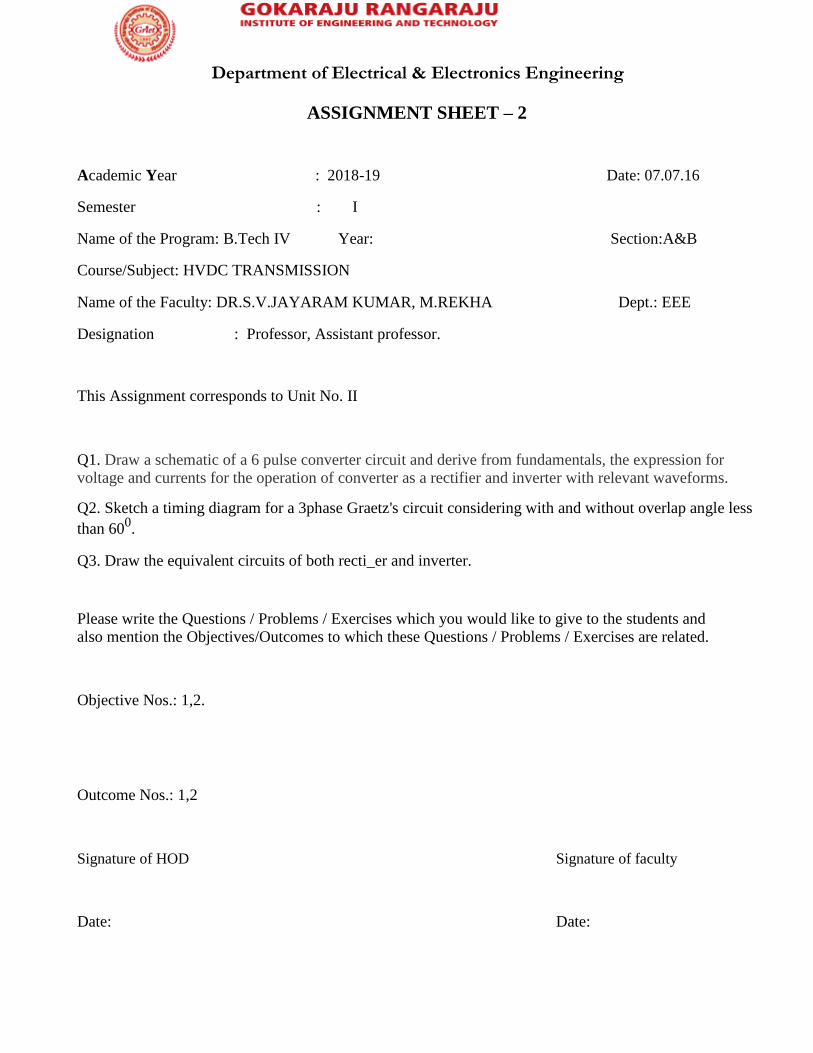
ASSIGNMENT SHEET – 2
Academic Year : 2018-19 Date: 07.07.16
Semester : I
Name of the Program: B.Tech IV Year: Section:A&B
Course/Subject: HVDC TRANSMISSION
Name of the Faculty: DR.S.V.JAYARAM KUMAR, M.REKHA Dept.: EEE
Designation : Professor, Assistant professor.
This Assignment corresponds to Unit No. II
Q1. Draw a schematic of a 6 pulse converter circuit and derive from fundamentals, the expression for voltage and currents for the operation of converter as a rectifier and inverter with relevant waveforms.
Q2. Sketch a timing diagram for a 3phase Graetz's circuit considering with and without overlap angle less
than 600.
Q3. Draw the equivalent circuits of both recti_er and inverter.
Please write the Questions / Problems / Exercises which you would like to give to the students and also mention the Objectives/Outcomes to which these Questions / Problems / Exercises are related.
Objective Nos.: 1,2.
Outcome Nos.: 1,2
Signature of HOD
Signature of faculty
Date:
Date:
Department of Electrical & Electronics Engineering
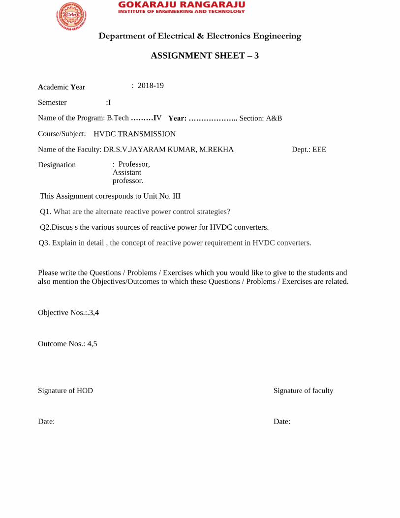
ASSIGNMENT SHEET – 3
Academic Year
: 2018-19
Semester :I
Name of the Program: B.Tech ………IV Year: ……………….. Section: A&B
Course/Subject: HVDC TRANSMISSION
Name of the Faculty: DR.S.V.JAYARAM KUMAR, M.REKHA Dept.: EEE
Designation : Professor, Assistant professor.
This Assignment corresponds to Unit No. III
Q1. What are the alternate reactive power control strategies?
Q2.Discus s the various sources of reactive power for HVDC converters.
Q3. Explain in detail , the concept of reactive power requirement in HVDC converters.
Please write the Questions / Problems / Exercises which you would like to give to the students and also mention the Objectives/Outcomes to which these Questions / Problems / Exercises are related.
Objective Nos.:.3,4
Outcome Nos.: 4,5
Signature of HOD
Signature of faculty
Date:
Date:

Department of Electrical & Electronics Engineering
ASSIGNMENT SHEET – 4
Academic Year : 2018-19 Date: 22.09.16.
Semester : I
Name of the Program: B.Tech ………IV Year: ……………….. Section:A&B
Course/Subject: HVDC TRANSMISSION
Name of the Faculty: DR.S.V.JAYARAM KUMAR,
M.REKHA Dept.:EEE
Designation : Professor, Assistant professor.
This Assignment corresponds to Unit No. IV
Q1. Classify the faults on a converter
Q2. Write a brief note on short circuits in a converter.
Q3. Explain the difference between the A.C. circuit breaker and H.V.D.C. circuit breaker.
Q4. Explain the causes of over voltages on D.C. side of H.V.D.C converter.
Please write the Questions / Problems / Exercises which you would like to give to the students and also mention the Objectives/Outcomes to which these Questions / Problems / Exercises are related.
Objective Nos.: 5
Outcome Nos.: 7
Signature of HOD
Date:
Signature of faculty
Date:

Department of Electrical & Electronics Engineering
ASSIGNMENT SHEET – 5
Academic Year
: 2018-19
Semester :I
Name of the Program: B.Tech IV Year: ………IV……….. Section:A&B
Course/Subject: HVDC TRANSMISSION
Name of the Faculty: DR.S.V.JAYARAM KUMAR, M.REKHA Dept.:EEE.
Designation :Professor, Assistant professor.
This Assignment corresponds to Unit No. V
Q1. Derive the expression for a total harmonic distortion in a 12 pulse converter.
Q2. How the voltage and current harmonics are calculated.
Q3. Explain in detail the non characteristic harmonics
Please write the Questions / Problems / Exercises which you would like to give to the students and also mention the Objectives/Outcomes to which these Questions / Problems / Exercises are related.
Objective Nos.: 5
Outcome Nos.: 6,7
Signature of HOD
Signature of faculty
Date:
Date:

Department of Electrical & Electronics Engineering
TUTORIAL SHEET - 1
Academic Year
: 2018-19
Date: 30.06.16.
Semester : I
Name ofthe Program: B.Tech IV Year: Section:A
&B
Course/Subject: HVDC TRANSMISSION
Name of the Faculty: DR.S.V.JAYARAM KUMAR, M.REKHA Dept.: EEE
Designation : Professor, Assistant professor.
This Tutorial corresponds to Unit No. I
Q1. What is the need of interconnection of systems?
Q2. Explain the merits of connecting HVAC systems by HVDC tie-lines?
Q3. Discuss the relative merits and demerits of using E.H.V.A.C transmission and HVDC transmission for bulk power transmission over long distances.
Please write the Questions / Problems / Exercises which you would like to give to the students and also mention the Objectives/Outcomes to which these Questions / Problems / Exercises are related.
Objective Nos.: 1,2
Outcome Nos.: 1,2
Signature of HOD
Signature of faculty
Date:
Date:

Department of Electrical & Electronics Engineering
TUTORIAL SHEET - 2
Academic Year
: 2018-19
Semester :I
Name of the Program : B.Tech IV Year Section:A&B
Course/Subject: HVDC TRANSMISSION
Name of the Faculty: DR.S.V.JAYARAM KUMAR, M.REKHA Dept.: EEE
Designation : Professor, Assistant professor.
This Tutorial corresponds to Unit No. II
Q1. With the help of neat sketches, analyze a six pulse recti_er bridge circuit with
an overlap angle greater than 600. Deduce the relevant equations and draw the necessary graphs.
Q2 . With the help of neat sketches, analyze a six pulse recti_er bridge circuit with
an overlap angle less than 600. Deduce the relevant equations and draw the
necessary graphs.
Please write the Questions / Problems / Exercises which you would like to give to the students and also mention the Objectives/Outcomes to which these Questions / Problems / Exercises are related.
Objective Nos.: 1,2
Outcome Nos.: 1,2
Signature of HOD
Signature of faculty
Date:
Date:

Department of Electrical & Electronics Engineering
TUTORIAL SHEET - 3
Academic Year
: 2018-19
Semester : I
Name of the Program: B.Tech IV Year: Section:A
&B
Course/Subject: HVDC TRANSMISSION
Name of the Faculty: DR.S.V.JAYARAM KUMAR, M.REKHA
Dept.: EEE
Designation : Professor, Assistant professor.
This Tutorial corresponds to Unit No. III
Q1. Write a short notes on:
(a) Modeling of H.V.D.C. links
(b) P.U. system for d.c. quantities.
Q2. Compare simultaneous and sequential methods of power flow analysis.
Please write the Questions / Problems / Exercises which you would like to give to the students and also mention the Objectives/Outcomes to which these Questions / Problems / Exercises are related.
Objective Nos.:.3,4
Outcome Nos.: 4,5
Signature of HOD
Signature of faculty

Department of Electrical & Electronics Engineering
TUTORIAL SHEET - 4
Academic Year
: 2018-19
Date: 22.09.16.
Semester : I
Name of the Program: B.Tech IV Year: Section:A
&B
Course/Subject: HVDC TRANSMISSION
Name of the Faculty: DR.S.V.JAYARAM KUMAR, M.REKHA Dept.: EEE
Designation : Professor, Assistant professor.
This Tutorial corresponds to Unit No. IV
Q1. Explain the effects of single commutation failure in converter.
Q2. Explain briefly the factors on which recovery from a commutation failure depends.
Q3. Explain the fault clearing process in H.V.D.C. poles. Explain how are the H.V.D.C.equipment protected against prolonged short circuit currents
though there is no H.V.D.C. circuit breaker on H.V.D.C. pole side.
Please write the Questions / Problems / Exercises which you would like to give to the students and also mention the Objectives/Outcomes to which these Questions / Problems / Exercises are related.
Objective Nos.: 6
Outcome Nos.: 7
Signature of HOD
Signature of faculty
Date:
Date:
Department of Electrical & Electronics Engineering
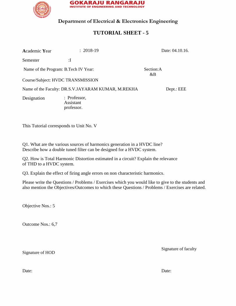
TUTORIAL SHEET - 5
Academic Year
: 2018-19
Date: 04.10.16.
Semester :I
Name of the Program: B.Tech IV Year: Section:A
&B
Course/Subject: HVDC TRANSMISSION
Name of the Faculty: DR.S.V.JAYARAM KUMAR, M.REKHA Dept.: EEE
Designation : Professor, Assistant professor.
This Tutorial corresponds to Unit No. V
Q1. What are the various sources of harmonics generation in a HVDC line? Describe how a double tuned filter can be designed for a HVDC system.
Q2. How is Total Harmonic Distortion estimated in a circuit? Explain the relevance of THD to a HVDC system.
Q3. Explain the effect of firing angle errors on non characteristic harmonics.
Please write the Questions / Problems / Exercises which you would like to give to the students and also mention the Objectives/Outcomes to which these Questions / Problems / Exercises are related.
Objective Nos.: 5
Outcome Nos.: 6,7
Signature of HOD
Signature of faculty
Date:
Date:
Department of Electrical & Electronics Engineering
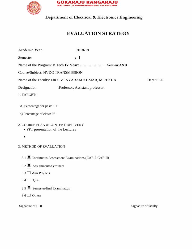
EVALUATION STRATEGY
Academic Year : 2018-19
Semester : I
Name of the Program: B.Tech IV Year: ……………….. Section:A&B
Course/Subject: HVDC TRANSMISSION
Name of the Faculty: DR.S.V.JAYARAM KUMAR, M.REKHA Dept.:EEE
Designation :Professor, Assistant professor.
1. TARGET:
A) Percentage for pass: 100
b) Percentage of class: 95
2. COURSE PLAN & CONTENT DELIVERY
• PPT presentation of the Lectures
•
3. METHOD OF EVALUATION
3.1 Continuous Assessment Examinations (CAE-I, CAE-II)
3.2 Assignments/Seminars
3.3 Mini Projects
3.4 Quiz
3.5 Semester/End Examination
3.6 Others
Signature of HOD
Signature of faculty
Department of Electrical & Electronics Engineering
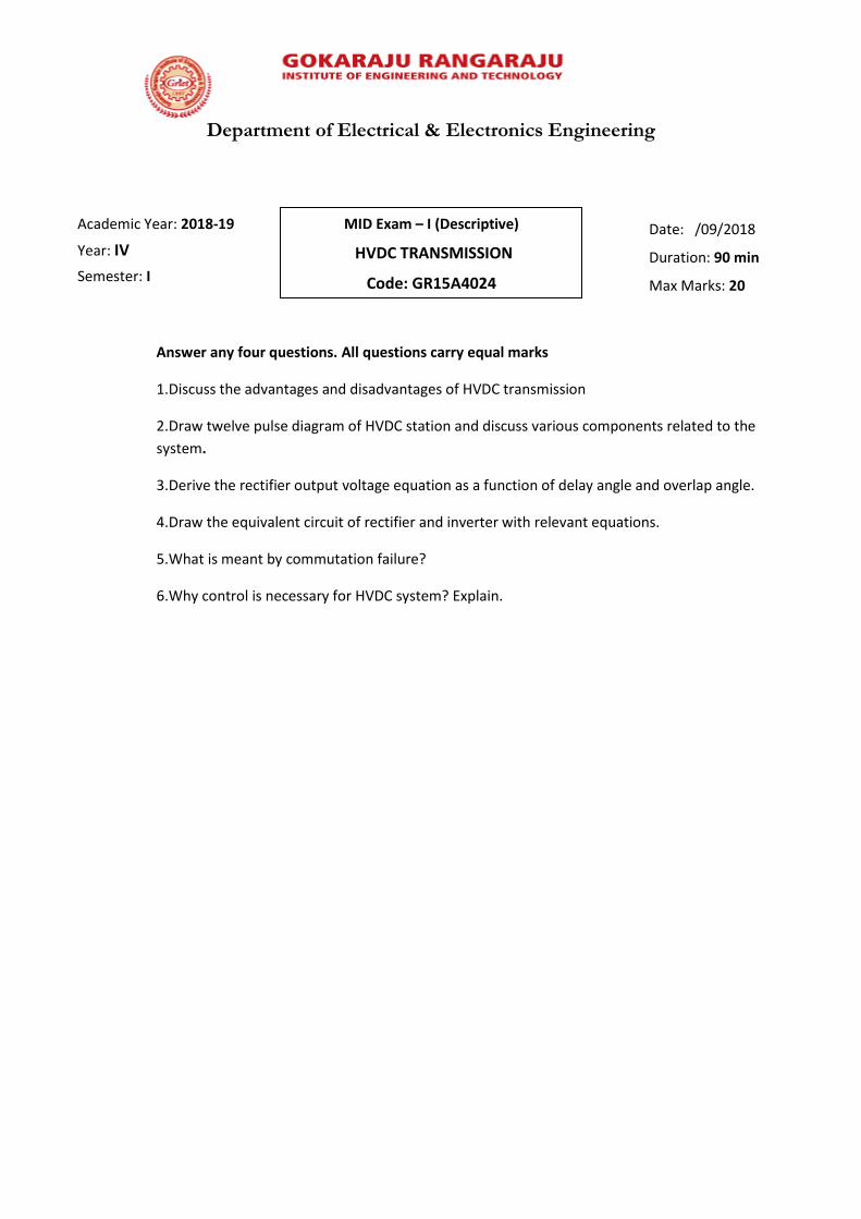
Answer any four questions. All questions carry equal marks
1.Discuss the advantages and disadvantages of HVDC transmission
2.Draw twelve pulse diagram of HVDC station and discuss various components related to the
system.
3.Derive the rectifier output voltage equation as a function of delay angle and overlap angle.
4.Draw the equivalent circuit of rectifier and inverter with relevant equations.
5.What is meant by commutation failure?
6.Why control is necessary for HVDC system? Explain.
Academic Year: 2018-19
Year: IV
Semester: I
MID Exam – I (Descriptive)
HVDC TRANSMISSION
Code: GR15A4024
Date: /09/2018
Duration: 90 min
Max Marks: 20

Department of Electrical & Electronics Engineering
Roll No.
Note: Answer all the questions. All questions carry equal marks.
1.In a monopolar system usually the pole is
(a)Positive and Negative (b)Positive (c)Negative (d)Alternatively positive and negative
2.The break-even distance is the distance beyond which
(a)DC transmission is economical (b)AC transmission is economical (c) cost of both
systems are the same (d) both(b) and (c).
3.The first HVDC scheme in India is
(a)Vidhyachal back-to-back system (b)Delhi-Rihand 500kV system(c)Chandrapur-Padghe
scheme(d)Sileru-Barsoor system.
4.12-pulse converters are used in modern converters because of
(a)reduced current (b)reduced ripple (c)increased voltage and reduced harmonics
(d)both(b) and (c)
5.The output voltage of a converter is changed by varying
(a) α (b)µ (c) ɣ (d)any one α,µ,ɣ
Fill in the blanks
1.HVDC transmission line commercially began in the year-------------------.
2.Modern HVDC system are all----------pulse converters.
3.Coolant used in thyristor/IGBT valves is-------------------.
4.In a bipolar system one conductor is----------------and the other is ------------------.
5.IGBT converters operate on the principle of ------------------ source converter.
Academic Year: 2018-19
Year: IV
Semester: I
MID Exam – I (Objective)
HVDC Transmission
Code: GR15A4024
Date: /09/2018
Duration: 30 min
Max Marks: 05

Department of Electrical & Electronics Engineering
Answer any three questions. All questions carry equal marks
1.Obtain the equation for harmonics for 12-pulse converter. Also discuss the impact of harmonics on
the system. (CO5)
2.What is meant by individual phase control used for firing the HVDC valves. Explain with neat
diagram. (CO4)
3. Explain the significance of earthing in HVDC system. (CO6)
4.Discuss the various faults exist in Converter Station. (CO7)
Academic Year: 2018-19
Year: IV
Semester: I
MID Exam – II (Descriptive)
HVDC TRANSMISSION
Code: GR15A4024
Date: /10/2018
Duration: 90 min
Max Marks: 15

Department of Electrical & Electronics Engineering
Roll No.
Note: Answer all the questions. All questions carry equal marks.
1.Commutation failure occurs usually in [ ]
(a)Rectifiers (b)Inverters (c)Both inverters and rectifiers (d)controllers
2.In HVDC-VSC schemes filters are used [ ]
(a)only on the AC side (b) only on the DC side (c)both AC and DC side (d)no filter is needed.
3.During commutation in a converter [ ]
(a)voltage is exchanged (b)current is transformed from one valve to the other(c)DC voltage is
blocked(d)none of the above.
4. Power transfer in DC line depends on [ ]
(a)sending and receiving end voltages (b)number of pulses in the rectifier(c)line
resistance(d)none of the above
5. VDCOL controlling is done and is necessary when [ ]
(a)low voltage due to faults (b) to regulate DC current depending on DC voltage due to fault
on AC side (c)to regulate DC current when DC voltage dips (d) to regulate AC current under
fault
6.In a 12-pulse converter, the phase difference between the two 6-pulse bridges is-------------
7. If pulse number =p and k is an integer, voltage harmonic generated on the DC side is------
8. Most frequent type of faults in DC system is -----------------------------
9. Increase in pulse number has the effect of increasing the lowest harmonic number
(True/False)
10. Advantage of DC link for power transfer is more economical(True/False)
Academic Year: 2018-19
Year: IV
Semester: I
MID Exam – II(Objective)
HVDC Transmission
Code: GR15A4024
Date: /10/2018
Duration: 30 min
Max Marks: 05

Department of Electrical & Electronics Engineering
IV B.Tech-(HVDC) I Sem I Mid Marks(2018-19)
S.NO 1 (CO1)
2 (CO3)
3 (CO2) 4 ( CO1)
15241A0261 4 3 5
15241A0262
15241A0263 3
15241A0264 4 2 2
15241A0265 4 4 4
15241A0266 5 1 4
15241A0267 5 2 4
15241A0268 5 2 3
15241A0269 2 4 1
15241A0270 4 2
15241A0271 5 5 5
15241A0272 5 5 5
15241A0273 5 2 5
15241A0274 0 0 0 0
15241A0275 5 2 4
15241A0276 3 2
15241A0277 5 5 4
15241A0278 3 1 2
15241A0279 3 3 2
15241A0280 4 4
15241A0281 4 3 3
15241A0282 4 3 5 4
15241A0283 3 2
15241A0284 4 2 5
15241A0285 5 2 4
15241A0286 4 3
15241A0287 4 4
15241A0288 3 1 2
15241A0289 4 2 5
15241A0290
15241A0291 3 2
15241A0292 5 5 5
15241A0293 5 4 2
15241A0294 3 3
15241A0295 5 2 5
15241A0296 2 4
15241A0297 5 2 4
15241A0298 4 2
15241A0299 2 3 3
15241A02A0 2 1

Department of Electrical & Electronics Engineering
15241A02A1 2 2 2
15241A02A2 3
15241A02A3 3 2 3
15241A02A5 3 3 3
15241A02A6 3 2
15241A02A7 3 3 4
15241A02A8
15241A02A9 4 2 3
15241A02B0 3 2 1
15241A02B1 5 2 4
15241A02B2 3
15241A02B3 5 5 5
15241A02B4 5 2
15241A02B5 3 2 4
15241A02B6 5 5 5
15241A02B7 5 2 5
15241A02B8 5 5 4
15241A02B9 5 5
15241A02C0 4 2 5
16245A0213 5 1 5
16245A0214 3 5 3
16245A0215 2 2 1
16245A0216 4 2
16245A0217 5 5 5
16245A0218 3 2
16245A0219 4 2 3
16245A0220 2 2 1
16245A0221 5 4 2
16245A0222 4 2 2
16245A0223 2 3
16245A0224 4 2 1
Total 245 148 44 165
No of students attempted(NSA) 64 58 13 48
Attempt %=(NSA/Total no of students)*100 90.14 81.69 18.31 67.61
Average (attainment)= Total/NSA 3.83 2.55 3.38 3.44
Attainment % = (Total/no.of max marks*no.of
students attempted)*100 76.56 51.03 67.69 68.75
1 2 3 4
1 (CO1)
2 (CO3)
3 (CO2) 4 ( CO1)
CO1 72.65
CO2 67.69
CO3 51.03
CO4
CO5
CO6
CO7

Department of Electrical & Electronics Engineering
IV B.Tech-(HVDC) I Sem II Mid Marks(2018-19)
S.NO 1 (CO5)
2 (CO4)
3 (CO6) 4 ( CO7)
15241A0261 5 2
15241A0262
15241A0263
15241A0264 5 2
15241A0265 4 3 1
15241A0266 5 1 2
15241A0267 5 5 5
15241A0268 4 5 3
15241A0269 2 1 1
15241A0270 5 5 1
15241A0271 1 3
15241A0272 5 5 1
15241A0273 5 5 3
15241A0274 5 1
15241A0275 5 5 5
15241A0276 1 5 3
15241A0277 5 1 5
15241A0278 2 1 1
15241A0279 5 1
15241A0280 5 1 3
15241A0281 5 5 4
15241A0282 5 5 5
15241A0283 5 1 3
15241A0284 5 5 5
15241A0285 5 5 5
15241A0286 2 1 1
15241A0287 1 1 2
15241A0288 1 2
15241A0289 5 1 2
15241A0290 2 2
15241A0291 3 1
15241A0292 5 5 5
15241A0293 3 5 5
15241A0294 1 3
15241A0295 4 5
15241A0296 1 5
15241A0297 5 5 5
15241A0298 3 5 4
15241A0299 2 2
15241A02A0 1 3
15241A02A1 5 5 3
15241A02A2 5 4

Department of Electrical & Electronics Engineering
15241A02A4 5 3 4
15241A02A5 3 1
15241A02A6 5 2
15241A02A7 5 5 4
15241A02A8 5 5 4
15241A02A9 5 3
15241A02B0 3 2 3
15241A02B1 5 5 2
15241A02B2 5 5
15241A02B3 5 5 5
15241A02B4 5 5 3
15241A02B5 5 5 4
15241A02B6 5 5 5
15241A02B7 5 5 5
15241A02B8 5 5 3
15241A02B9 5 3
16245A02C0 5 4
16245A0213 1 4
16245A0214 5 5 3
16245A0215 5 5 1
16245A0216 5 4
16245A0217 5 5 3
16245A0218 2 1
16245A0219 5 5 4
16245A0220 1 4
16245A0221 5 4 1
16245A0222 2 1 3
16245A0223 4 1 4
16245A0224 5 1 4
Total 216 212 55 175
No of students attempted(NSA) 52 46 30 55
Attempt %=(NSA/Total no of students)*100 73.24 64.79 42.25 77.46
Average (attainment)= Total/NSA 4.15 4.61 1.83 3.18
Attainment % = (Total/no.of max marks*no.of
students attempted)*100
83.08 92.17 36.67 63.64
1 2 3 4
1 (CO5)
2 (CO4)
3 (CO6) 4 ( CO7)
CO1
CO2
CO3
CO4 92.17
CO5 83.08
CO6 36.67
CO7 63.64

Department of Electrical & Electronics Engineering
Cognitive Level Mapping
Co’s Cognitive level learning 1 2 3 4 5 6
1 √ 2 √ 3 √ 4 √ 5 √ 6 √ 7 √
Cognitive Learning Levels
CLL 1: Remembering
CLL 2: Understanding
CLL 3: Applying
CLL 4: Analyzing
CLL 5: Evaluating
CLL 6: Creating

Department of Electrical & Electronics Engineering

Department of Electrical & Electronics Engineering

Department of Electrical & Electronics Engineering
FEEDBACK FROM STUDENTS

Department of Electrical & Electronics Engineering

Department of Electrical & Electronics Engineering
RESULT ANALYSIS
Year
Total
No.
Of
Studen
ts
appear
ed
Total
No. of
Stude
nts
Passe
d
No. of
Stude
nts
Failed
GRA
DE
=10
GRADE
=9
GR
AD
E=
8
GRA
DE=
7
GRA
DE=
6
GRA
DE=
5
GRA
DE=
4
PASS
PERCE
NTAG
E(%)
2018-19 140 132 08 16 18 16 17 38 22 05 94.28
2017-18
124 121 03 35
(<60
%)
32
(60-
70%)
54
(>7
0%
)
97.58
2016-17
140 130 10 31
(<60
%)
42
(60-
70%)
57
(>7
0%
)
92.85

• The network of transmission and distribution lines is formed by three phase alternating current system. • For longer lines and higher power transfer, higher transmission voltages are necessary. • The Electrical Power System (Network) is formed by a 3 phase, 50 Hz, AC System with several AC voltage levels for
generation, transmission, distribution and utilisation. • Choice of transmission voltage depends on power and distance. •AC power transformers are installed in various transmission and distribution substations and near load points to step-up or
step down AC Voltages to required levels.
•The entire AC Network operates synchronously at common prevailing frequency (50 Hz, ± 3%). •3 Phase AC System has a tendency to operate naturally in synchronism and the operation and control is very easy.
•Power transfer through an AC transmission link is given by In an AC Network AC Power transfer through a particular AC line cannot be controlled easily, quickly and accurately. • The sin δ causes transient stability limit which is almost 50% of steady state limit. • Reactive power flow causes additional (I2 Rt) transmission losses and voltage regulation problems. •For very long, high power transmission lines (> 800km;> 1000 MW), for System Interconnections between two or
more independently controlled AC Networks (Regional Grids) and for long submarine cables. •

•High Voltage Direct Current Transmission (HVDC) links are preferred due to technical and economic superiority over equivalent EHV AC transmission links for same power/distance. •Nominal Power transfer through an HVDC Link is given by: •The H VDC power transfer can be controlled quickly and accurately by thyristor control and tap changer control. •There are no problems of reactive power flow, voltage fluctuations and high transmission losses.
•However HVDC voltages cannot be easily stepped up or stepped down. • HVDC requires costly and complex substations, high technology, complex controls. •The Modern TransmissionNetwork continues to be of3 phase 50 Hz, AC System with a few specific HVDC
links integrated with the 3 phase AC Network. •HVDC links are considered only for specific projects such as :
• A few long high power, point to point, 2 terminal HVDC Transmission Systems. (e.g. ± 500 kV, 1500
MW, 820 km, Rihand-Deihi Bipolar 2T HVDC System (UP, India, 1992): ± 500 MW 1500 MW, 850 km Chandrapur-Padaghe Bipolar 2T HVPC System (Maharashtra, India, 1997)
• Back to Back Interconnecting HVDC Coupling Systems between Regional Grids (e.g. Vindhyachal sack-to-Back, 500 MW Link between Western Region and Northern Region, India (1989); Chandrapur Back-to-Back, 1000 MW Link between Western Region and Southern Region, India, 1996) • Multi-terminal HVDC Interconnecting Systems (e.g. 5-Terminal Hydro-Quebeck : New England, USA/Canada, 1987-96) • High Voltage long high power Cable transmission. (e.g. UK? France submarine Link, 2000 MW, 65 km).

•First commercial High Voltage Direct Current transmission system (HVDC) was introduced during 1953. • With the successfully development of high power thyristor valves in early 1970’s, the HVDC transmission systems have become a technically and commercially viable alternative to EHVAC transmission particularly for (1) long distance bulk power transmission; (2) Submarine cable transmission and (3) system interconnection. • For these three applications HVDC transmission systems have a distinct superiority over EHVAC and are being increasingly preferred. Choice of a Transmission System • The choice of the voltage is made from HVAC, EHV-AC, HVDC on the basis of the following economical and technical
considerations.
Economic Considerations
• Capital cost of transmission systems:
• Cost of line conductors, towers, insulators, installation land/right of way.
• Capital cost of substations, intermediate substations, compensating substations, conversion substations, substation equipment like transformers, switchgear; substation area, buildings.
• Cost of energy losses, maintenance.
• Needs of future expansion and associated cost.
• Economic aspects telated with availability, reliability. • Economic strategy for Energy Transmission. Technical Considerations
• Length of the transmission line and total power to be transferred

• Control over Power Transfer, magnitude, rate of change. • Existing network and long term plans. • Choice of voltage considering power flow.
• Stability considerations related with power flow and frequency disturbances.
• Reliability and security of power flew. Availability of transmission link.
• Reactive power compensation and voltage control. • Switching requirement. • Right of way for transmission lines. • Radial or Mesh. • 21’ or 31’ or MT. • Type of line :
Overhead/underground/submarjne cables. • Network configuration, parallel lines, T-offs, multi-terminals etc. Application of EHV-AC Transmission • Voltage can be stepped-up or stepped-down in transformer substations to have economical transmission voltage. • Lines can be tapped easily, extended easily. • Parallel lines can be easily added. • Control of Power flow in the Network is simple and natural. • Power flow in a particular line cannot be controlled easily and quickly. • Equipments are simple and reliable without need of high- tech. • Operation is simple and adopts naturally to the synchronously operating AC systems. • Generation and distribution is by AC. Special Features and Technical Consideration for EHVAC Lines • The most important requirement of an EHV-AC transmission line is power transfer ability based on transient stability limit.

at δ = 30°, sin δ = 0.5. Hence AC line can transfer only 50% of its steady state power limit. • EHV-AC line needs compensation of reactive power. This is provided by SVS ; shunt reactors, Shunt capacitors, etc. installed in sub-stations. Intermediate substations are necessary at interval of 250 km to 400 km. • Power transfer ability of EHV lines may be increased by using series capacitors or adding a parallel line. For high power lines several parallel circuits may be necessary. • The line design is based on limits of corona, radio interference, TV interference, electrical field at ground level, etc. • For EHV-AC lines the voltage stress at conductor surface should be kept below critical voltage. For achieving this, the use of bundled conductors is essential. Bundle conductors reduce the corona losses, Radio Interference, TV Interference. • Switching surges occur during opening and closing f unloaded lines. Line insulation is designed on the basis of switching overvoltages. Appropriate circuit-breakers and compensation is necessary to limit switching surges. Insulation co-ordination is achieved with the use of suitable surge arresters. • EHV-AC lines and Network have high short-circuit levels and associated protection problems. HVDC interconnection limits the short-circuit levels of both the AC networks. • EHV-AC lines experience power swings during system disturbances, switching and faults. Protection of EHV-AC lines is designed to block during low power swings. • EHV-AC lines transmit bulk power. Outage of a line causes stability problems in the network. Hence alternative transmission paths should be plannèd along with the protection system design. For each radial line, at least two three phase circuits are, necessary. • In large interconnected networks, the effect of a major fault in one of the networks can result in cascade tripping and a large scale blackout To prevent this the Network Segregation is carried out. HVDC interconnection eliminates the problem of cascade tripping.
Applications of HVDC transmission
• Long distance high Power transmission by overhead lines. • Medium and long high power submarine or underground cables. • System interconnection by means of overhead lines or underground/submarine cables or back to back HVDC coupling stations. • Multi-Terminal HVDC System for interconnecting three or more 3 phase AC systems. • Frequency conversion (6O Hz —50 Hz ; 50 Hz —25
‘Hz) • Incoming lines in megacities.

Schematic diagram of an HVDC Transmission System
• An HVDC link has an AC system at each end. • The AC power is converted by thyristor-convertor valves into DC power. • The energy is transmitted in HVDC form to the other end. •At the other end the DC power is inverted in thyristor-convertor valves and fed into the receiving system. •An 2-Terminal HVDC transmission system has an HVDC convertor substation at each end and an HVDC transmission line in
between. • In case of back-to-back coupling station, the rectifier and inverter are at the same place and there is no HVDC line. •A back-to-back HVDC station provides an asynchronous tie between two adjacent AC Networks.

Choice of HVDC Transmission System
• Long, high power transmission
• For long distance, high power transmission lines HVDC transmission systems are preferred due to their economic advantage and exact, fast and easy control of power flow from generating station to load centre.
• Though HVDC system needs costly terminal substations, the line cost is lower than that of equivalent AC line.
• Power flow can be controlled.
• Line losses are low.
• The per km cost of HVDC line is lesser than that of an equivalent 3 phase double circuit AC line.
• For equal power transfer, the number of conductors for 3 phase AC line is 6 to 24 as against only 2 numbers required for Bipolar HVDC line.

•System Interconnections
• Neighbouring independently controlled AC Networks are interconnected by system interconnections.
• System interconnection is either by EHV-AC/HVAC or HVDC.
• The basic function of an interconnection is to transfer energy from surplus zone to deficit zone.
• When neighbouring AC Networks are connected by and AC interconnection they start operate synchronously at the same frequency. AC interconnection is called synchronous tie.
• When neighbouring AC Networks are interconnected by HVDC interconnection, they can continue to have their independent load frequency control.(Asynchronous tie)
•System interconnection has following major
Lesser overall installed capacity to meet the peak demand. Lesser spinning reserves.
Overall economic generation by optimum use of high capacity economical generating plants.
Better use of energy reserves such as hydro, thermal, nuclear. Better system support to week network.
Better system support to network having emergency due to outage of a plant or a line. Stronger grid with stable frequency.advantages.
EHV-AC interconnection: It is simple. Power flow adapts naturally to the needs and prevailing surplus deficit between interconnected networks. Voltages and connections can be made suitably by using transformer connection.
The limitations of EHV-AC interconnections include: It is synchronous tie. Frequency disturbance in one zone is quickly transferred to the other. Power swings in one network affect the other network. A weak tie link gets tripped due to such power swings. Large interconnected networks suffer from cascade tripping. and overall black-outs in the event of major faults in any
of the network.

HVDC interconnections: It is an asynchronous tie. Frequency disturbance from one AC Network is not transferred to the other. Direction and magnitude of power flow can be changed quickly and accurately by controlling the characteristics of
rectifier/ inverter. Power swings and frequency disturbances in connected AC Network can be quickly dampened by modulating the
power flow through the HVDC interconnection. HVDC link can be used for interconnecting
HVDC link can be used for interconnection between two networks separated by sea or lake by using submarine
cables.systemshavingdifferentfrequencies. • Back-to-back asynchronous tie sub-stations
• In back-to- back HVDC coupling stations the interconnection is by a converter- substation without any transmission line. • The HVDC inverter and rectifier are installed in the same station. •Such a tie-link gives an asynchronous interconnection between two adjacent independently controlled AC networks.
• Multi-terminal HVDC Interconnection •Three or more AC networks can be interconnected asynchronously by means of a multi-terminal HVDC system. •Power flow from each connected AC Network can be controlled suitably. •Large power can be transferred. •Overall stability can be improved.
• Cable Transmission
• HVDC is preferred for underground or submarine-cable transmission over long distance at high voltage.
• The submarine cables are necessary to transfer power across oceans, lakes etc.
• In case of AC cables, the temperature rise due to charging currents forms a limit for loading.
• For each voltage rating there is a limit of length beyond which an AC cable cannot be used to transfer load current due to thermal limit.

• HVDC cables have no continuous charging currents and can transfer bulk power over long distances. Types of HVDC Systems
Monopolar HVDC system • This system has, only one pole and the return path is provided by permanent earth or sea. • The pole generally has negative polarity with respect to the earth. • In monopolar HVDC system the full power and current is transmitted through a line conductor with earth or sea as a return conductor. • The earth electrodes are designed for continuous full- current operation and for any overload capacity required in the specific case. • The sea or ground return is permanent and of continuous rating. • Monopolar HVDC systems are used only for low power rated links and mainly for cable transmission. Bipolar HVDC Transmission •This is most widely used of overhead long distance HVDC systems, for point-to-point power transfer.
•The HVDC substation and HVDC line has two poles, one positive and the other negative with respect to earth.
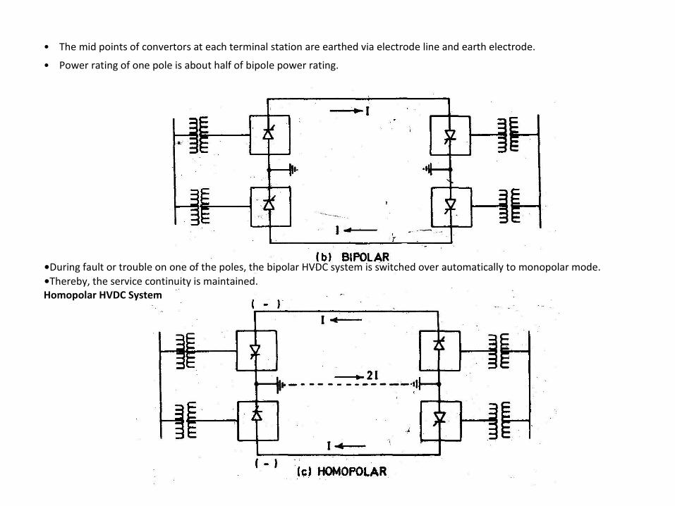
• The mid points of convertors at each terminal station are earthed via electrode line and earth electrode. • Power rating of one pole is about half of bipole power rating.
•During fault or trouble on one of the poles, the bipolar HVDC system is switched over automatically to monopolar mode. •Thereby, the service continuity is maintained. Homopolar HVDC System

•In such a system two transmission poles are of the same polarity and the return is through permanent earth. •Two homopolar overhead lines feeding to a common monopolar cable termination. • One overhead transmission tower carrying insulator strings supporting two homopolar transmission line conductors. •Applications of homopolar transmission are limited.
Limitations of HVDC Transmission Systems
• HVDC system does not have step-up and step-down transformers. • HVDC system does not have suitable HVDC circuit breakers. • HVDC Transmission cannot be used economically for main transmission, subtransmission, distribution. It is used only for
specific long distance/cable/interconnection projects. • Cost of HVDC terminal substations is very high. • Operation of HVDC transmission required continuous firing of thyristor valves. Controls of HVDC are complex. Several
additional abnormal conditions are possible on DC side and in controls. • HVDC substation require additional harmonic filters and shunt capacitors.
Converter station •The major components of a HVDC transmission system are converter stations where conversions from AC to DC (Rectifier
station) and from DC to AC (Inverter station) are performed. •A point to point transmission requires two converter stations. •The role of rectifier and inverter stations can be reyersed (resulting in power reversals) by suitable converter control. •The various components of a converter station are discussed below.


Converter unit •Each valve is used to switch in a segment of an AC voltage waveform. •The converter is fed by converter transformers connected in star/star and star/delta arrangements. •The valves are cooled by air, oil, water or freon. •Liquid cooling using deionized water is more efficient and results in the reduction
of station losses.
The ratings of a valve group are limited more by the permissible short circuit currents than steady state load requirements. •The design of valves is based on the modular concept where each module contains a limited number of sedes connected thyristor levels. • Valve firing signals are generated in the converter control at ground potential and are transmitted to each thyristor in the valve through a fiber optic light guide system. •The light signal received at the thyristor level is converted to an electrical signal using gate drive

amplifiers with pulse transformers. •The valves are protected using snubber circuits, protectiye firing and gapless surge arresters.
Converter Transformer • The converter transformer can have different configurations - (i) three phase, two winding,
(ii) single phase,three winding, (iii) single phase, two winding.
• The valve side windings are connected in star and delta with neutral point ungrounded. • On the AC side, the transformers are connected in parallel with neutral grounded . • The leakage reactance of the transformer is chosen to limit the short circuit currents through any valve. • The converter transformers are designed to withstand DC voltage stresses and increased eddy current losses due to harmonic currents. •One problem that can arise is due to the DC magnetization of the core due to unsymmetric firing of valves •In back to back links, which are designed for low DC voltage levels an extended delta configuration can result in identical
transformers being used in twelve pulse converter units.
Filters There are three types of filters used: AC filters : These are passive circuits used to provide low impedance, shunt paths for AC harmonic currents. Both tuned and damped filter arrangements are used. DC filters : These are similar to AC filters and are used for the filtering of DC harmonics. High frequency (RFIPLC) filters: These are connected between the converter transformer and the station AC bus to suppress any high frequency currents. Sometimes such filters are provided on high-voltage DC bus connected between the DC filter and DC line and also on the neutral side Reactive power source • Converter stations require reactive power supply that is dependent on the active power loading. • Fortunately, part of this reactive power requirement is provided by AC filters.
•In addition, shunt (switched) capacitors. synchronous condensors and static var systems are used depending on the speed of
control desired.
Smoothing reactor •A sufficiently large series reactor is used on DC side to smooth DC current and also for protection. •The reactor is designed as a linear reactor and is connected on the line side, neutral side or at intermediate location. DC switchgear •This is usually a modified AC equipment used to interrupt small DC currents. •DC breakers or metallic return transfer breakers (MRTB) are used, if required for interruption of rated load currents. •In addition to the equipment described above, AC switchgear and associated equipment for protection and measurement are also
part of the converter station.
EHV-AC Versus HVDC Transmission • For backbone network.
Voltage can be easily stepped-up, stepped-down. The network has natural tendency to maintain synchronism. Load-frequency control is easy and simple. Network can be tapped at intermediate points to feed underlying subtransmission network.
• Bulk power long distance transmission lines. HVDC proves economical above breakeven point. Number of lines are less. No
need of intermediate substations for compensation. •Stability of transmission system.
HVDC gives asynchronous tie and transient stability does not pose any limit. Line can be loaded upto thermal limit of the line or valves (whichever is lower).
•Line loading.
The permissible loading of an EHV-AC line is limited by transient stability limit and line reactance to almost one third of thermal rating of conductors. No such limit exists in case of HVDC lines.
•Surge impedance loading. Long ERV-AC lines are loaded to less than 0.8 Pn. No such condition is imposed on HVDC line.
•Voltage along the line.
Long EHV lines have varying voltage along the line due to absorption of reactive power. This voltage fluctuates with load. Such a problem does not arise in HVDC line. EHV-AC line remains loaded below its thermal limit due to the transient stability limit. Conductors are not utilized fully.

Number of lines.
EHVAC needs at least two three phase lines and generally more for higher power. HVDC needs only one bipole line for majority of application.
Intermediate substations.
EHV-AC transmission needs intermediate substations at an interval of 300 km for compensation.
HVDC line does not need intermediate compensating substation. Asynchronous tie.
System having different prevailing frequencies or different rated frequencies can be interconnected. HVDC link provides asynchronous tie. Frequency disturbance does not get tranferred large blackouts are avoided.
Better control. Power flow through HVDC tie line can be controlled more rapidly and accurately than that of EHV-AC interconnector. HVDC-Power flow can be increased at a rate of 30 MW per minute. This is not possible with EHV-AC line. Corona loss and radio interference. For the same power transfer and same distance, the corona losses and radio interference of DC systems is less than that of AC systems, as the required d.c. insulation level is lower than corresponding a.c. insulation. Power Transfer and Reactive Power. The main difference between EHV-AC and HVDC transmission systems is in control of Real Power flow and Reactive Power Flow. The AC line can be loaded upto transient stability limit which occurs at δ=300 and is given by AC line power cannot be changed easily, quickly and accurately as |V1 | and |V2| should be kept around rated voltage levels and angle δ cannot be changed easily. Secondly, the series reactance and shunt reactance of AC line result in reactive power flow, voltage regulation problems and additional transmission losses due to reactive component of current.

Power flow through HVDC link is given by By varying (Ud1 — Ud2) by means of thyristor converter control and tap-changer control; the power flow Pdc can be changed quickly, accurately and easily.
Secondly, HVDC transmission does not have series reactance and shunt reactance; reactive power flow. Hence voltage regulation problems and stability problems transmission losses etc. due to the flow of reactive power flow are absent in HVDC transmission systems. Transmission losses are low. Skin effect.
This is absent in d.c. current. Hence current density is uniformly distributed across the cross-section of the conductor.
Charging current.
Continuous line charging currents are absent in HVDC lines. Reactive Power (MVAr) does not flow continuously. Hence transmission losses are low.
Tower size.
The phase-to-phase clearance, phase to ground clearances and tower size is smaller for d.c. transmission as compared to equivalent AC transmission for same power and distance. Tower is simpler, easy to install and cheaper.
Number of conductors.
Bipolar HVDC transmission lines require two-pole conductors to carry DC power. Hence HVDC transmission becomes economical over AC transmission at long distance when the saving in overall conductors cost, losses, towers etc. compensates the additional cost of the terminal apparatus such as rectifiers and converters.
Earth return.
HVDC transmission can utilize earth return and therefore does not need a double circuit. EHV-AC always needs a double circuit.
Reactive power compensation.
HVDC line does not need intermediate reactive power compensation like EHV-AC line. Flexibility of operation.

Bipolar line may be operated in a monopolar mode by earth as a return path when the other pole develops a permanent fault.
Staging facility.
DC valves may be connected in series and parallel to get desired DC voltage and current. Multiterminal schemes are now possible.
Short-circuit level.
In AC transmission, additional parallel lines result in higher fault level at receiving end due to reduced equivalent reactance. When an exiting AC system is interconnected with another AC system by AC transmission line, the fault level of both he system increases. However, when both are interconnected by DC transmission, the fault level of each system remain unchanged.
Rapid power transfer.
The control of convertor valves permit rapid changes in magnitude and direction of power flow. Limitation is imposed by power generation and AC system conditions.
Static Power Conversion Adopted in HVDC Transmission
• A Bipolar HVDC transmission system has an HVDC terminal substation at each end. Each terminal substation has AC/DC convertor. The convertors change AC to DC or DC to AC.
• The convertor terminal operating in rectifier mode
changes AC power to DC power. Delay angle α is held at 15 to 18°.
• The convertor terminal operating in inverter mode
changes DC power to AC power. Extinction angle γ is held at 15 to 18°.
• The complete HVDC Tansmission transfers electric
power from one AC Network to another AC Network in the form of high voltage direct current.

The convertor has two types of circuits:
• Main circuit through which high power flows. This comprises convertor transformers, thyristor valves, busbars, series reactor etc. •Control and protection circuits for firing/blocking
the valves in desired sequence, monitoring etc.
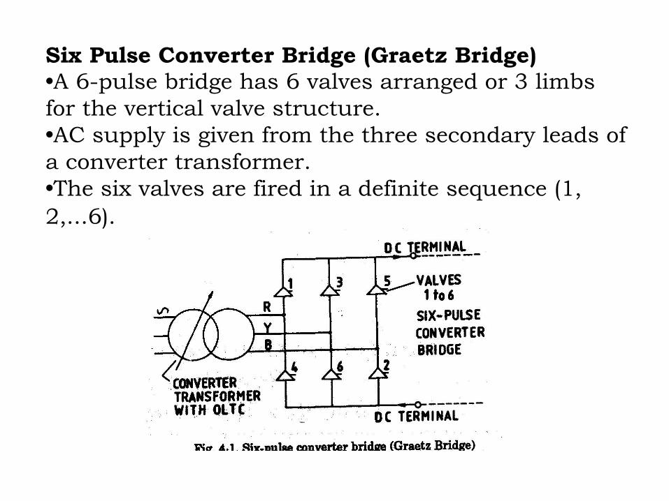
Six Pulse Converter Bridge (Graetz Bridge)
•A 6-pulse bridge has 6 valves arranged or 3 limbs
for the vertical valve structure.
•AC supply is given from the three secondary leads of
a converter transformer.
•The six valves are fired in a definite sequence (1,
2,...6).
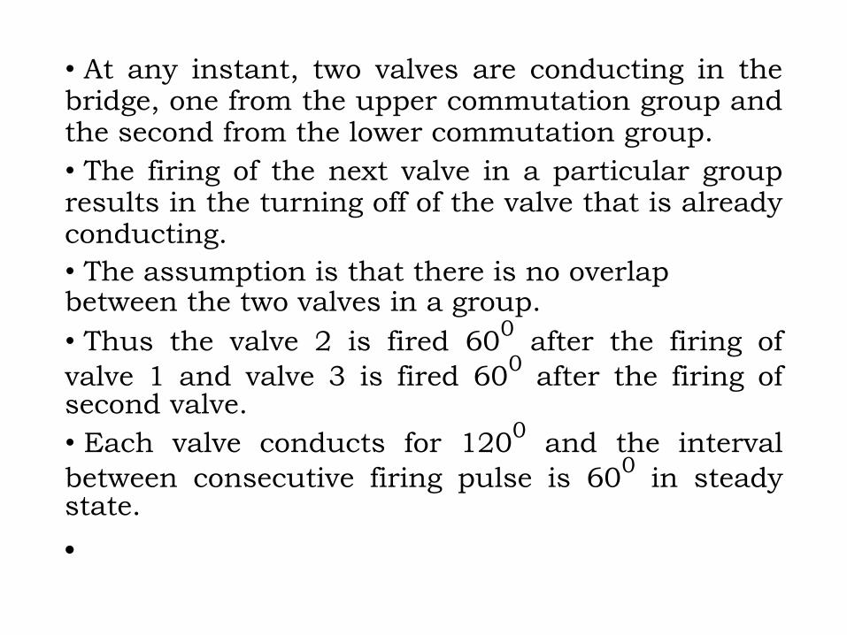
• At any instant, two valves are conducting in the bridge, one from the upper commutation group and the second from the lower commutation group. • The firing of the next valve in a particular group results in the turning off of the valve that is already conducting. • The assumption is that there is no overlap between the two valves in a group. • Thus the valve 2 is fired 60
0 after the firing of
valve 1 and valve 3 is fired 600 after the firing of
second valve. • Each valve conducts for 120
0 and the interval
between consecutive firing pulse is 600 in steady
state.
•
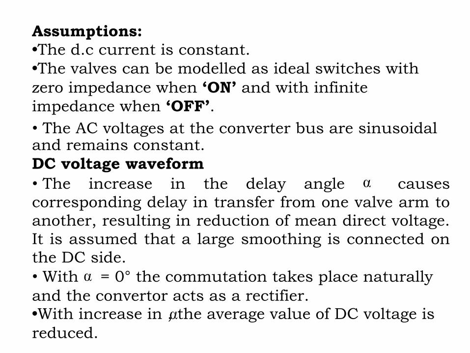
Assumptions:
•The d.c current is constant.
•The valves can be modelled as ideal switches with
zero impedance when ‘ON’ and with infinite
impedance when ‘OFF’.
• The AC voltages at the converter bus are sinusoidal and remains constant. DC voltage waveform • The increase in the delay angle causes corresponding delay in transfer from one valve arm to another, resulting in reduction of mean direct voltage. It is assumed that a large smoothing is connected on the DC side. • With = 0° the commutation takes place naturally and the convertor acts as a rectifier. •With increase in , the average value of DC voltage is
reduced.

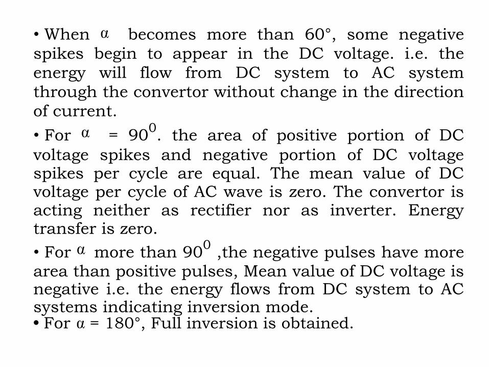
• When becomes more than 60°, some negative spikes begin to appear in the DC voltage. i.e. the energy will flow from DC system to AC system through the convertor without change in the direction of current.
• For = 900. the area of positive portion of DC
voltage spikes and negative portion of DC voltage spikes per cycle are equal. The mean value of DC voltage per cycle of AC wave is zero. The convertor is acting neither as rectifier nor as inverter. Energy transfer is zero.
• For more than 900 ,the negative pulses have more
area than positive pulses, Mean value of DC voltage is negative i.e. the energy flows from DC system to AC systems indicating inversion mode. • For = 180°, Full inversion is obtained.

Valve Voltage
• When the valve is conducting, this voltage is zero. • When valve is not conducting, and the other valve arm of the same group is conducting, the voltage across the non-conducting valve arm corresponds to phase to phase voltage of transformer secondary terminals. • Definition of Delay Angle . Delay angle is the time
expressed in electrical angle from the zero crossing(s)
of the idealised sinusoidal commutating voltage and starting of forward current conduction(s). •It can be conveniently understood as the angle
between the Instant of natural commutaton (zero
crossing) and instant of delayed commutation, (C).

•By delaying the triggering pulses, the duration of
conduction a cycle is reduced, thereby the average
value of DC voltage is reduced.
•By varying from zero to 90° elec., the no load
direct voltage changes from maximum(at = 0)
to zero (at = 90°).
•The following are noted: -
• = 00 Rectifier mode maximum DC voltage
• = 15° Rectifier mode reduced DC voltage • = 90° Rectifier mode No power transfer, Zero DC voltage • > 90° Inverter mode
• = 1800 Full inverter mode.

• The limits of delay angle are 0 to 450
• In practice, for normal rectifier operating mode, the delay angle is held between 50 to 15°. • The choice of has two opposite constraints.
(1) The reactive power demand of convertor valves reduces with reduction in delay angle . Hence smaller value of is preferred with respect to reactive power requirements (AC shunt compensation)
(2) But with smaller value of a the possibility of further increase in DC voltage on rectifier side is reduced.
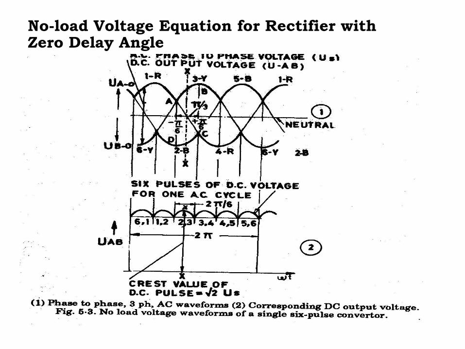
No-load Voltage Equation for Rectifier with Zero Delay Angle

•Secondary phase-to-phase voltage between
terminals A and B of a six-pulse convertor bridge .
•It is a sinusoidal voltage with an equation
•RMS value of the wave us, is equal to Us, which corresponds to phase-to-phase secondary voltage of a convertor transformer which feeds a six-pulse convertor. The crest value (peak value) of the voltage
waveform Usm occurs at XX and is given by

•Integrating u s over segment ABCD between — π/6
and + π/6 as shown is Fig. and dividing by
period π/3

where Us = secondary, rms, phase to phase voltage
• This fundamental, important equation co-relates DC voltage with phase-to-phase secondary AC voltage for a six-pulse-bridge. • For a six-pulse bridge
where Udo = No-load direct voltage with zero phase control, for a six pulse bridge
Us = Phase to phase rms voltage for secondary.

Rectifier Voltage Equations with No-Load and Delay Angle
• The average value of DC voltage of a six-pulse convertor unit can be determined by finding average value of one segment between (-π /6+ ) and ( +π /6+ ) with respect to peak phase to phase voltage at XX.

• Each segment covers π/3 duration. Hence
Where Usm = Crest value of phase to phase AC secondary voltage
=√2 Us
Us = Secondary phase to phase rms voltage
Ud = Direct voltage between terminals of one six-pulse unit operating at no load with delay angle .
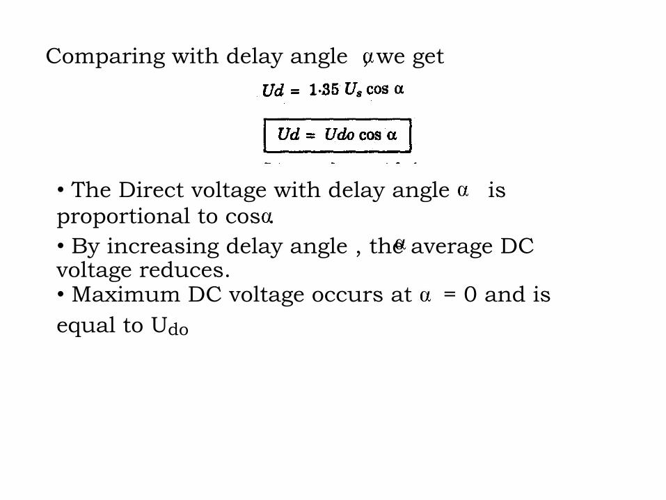
Comparing with delay angle , we get
• The Direct voltage with delay angle is proportional to cos . • By increasing delay angle , the average DC voltage reduces. • Maximum DC voltage occurs at = 0 and is
equal to Udo

Analysis of Graetz circuit with
overlap
• Due to the leakage inductance of the converter transformers and the impedance in the supply network, the current in a valve cannot change suddenly.
• Thus commutation from one valve to the next
cannot be instantaneous. • For example, when valve 3 is fired, the current
transfer from valve 1 to valve 3 takes a finite period during which both valves are conducting.
• This is called overlap and its duration is measured
by the overlap (commutation) angle ‘μ’.

•Each interval of the period of supply can be divided
into two subintervals
•In the first subinterval, three valves are conducting
and in the second subinterval, two valves are
conducting. This is based on the assumption that the
overlap angle is less than 60°.
•As the overlap angle increases to 60°, there is no
instant when only two valves are conducting.

• As the overlap angle increases beyond 600,there is a
finite period during an interval, when four valves conduct and the rest of the interval during which three valves conduct. Commutation
•The process of transfer of direct current from one
path to another with both paths carrying currents
simultaneously is called commutation. •The commutation process takes place sequentially
between two consecutive valve arms of group A
connected to positive terminal. • In forced commutation process, the commutating reactance of the load circuit of two valves undergoing commutaion causes the delay in the transfer from one path to another.
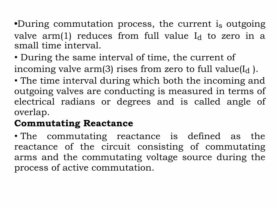
•During commutation process, the current is outgoing
valve arm(1) reduces from full value Id to zero in a small time interval.
• During the same interval of time, the current of
incoming valve arm(3) rises from zero to full value(Id ). • The time interval during which both the incoming and outgoing valves are conducting is measured in terms of electrical radians or degrees and is called angle of overlap. Commutating Reactance • The commutating reactance is defined as the reactance of the circuit consisting of commutating arms and the commutating voltage source during the process of active commutation.
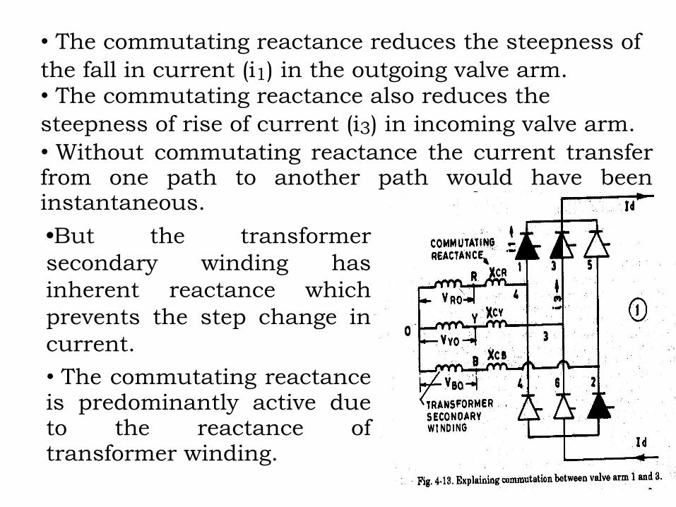
• The commutating reactance reduces the steepness of
the fall in current (i1) in the outgoing valve arm. • The commutating reactance also reduces the
steepness of rise of current (i3) in incoming valve arm. • Without commutating reactance the current transfer from one path to another path would have been instantaneous.
•But the transformer
secondary winding has
inherent reactance which
prevents the step change in
current.
• The commutating reactance is predominantly active due to the reactance of transformer winding.

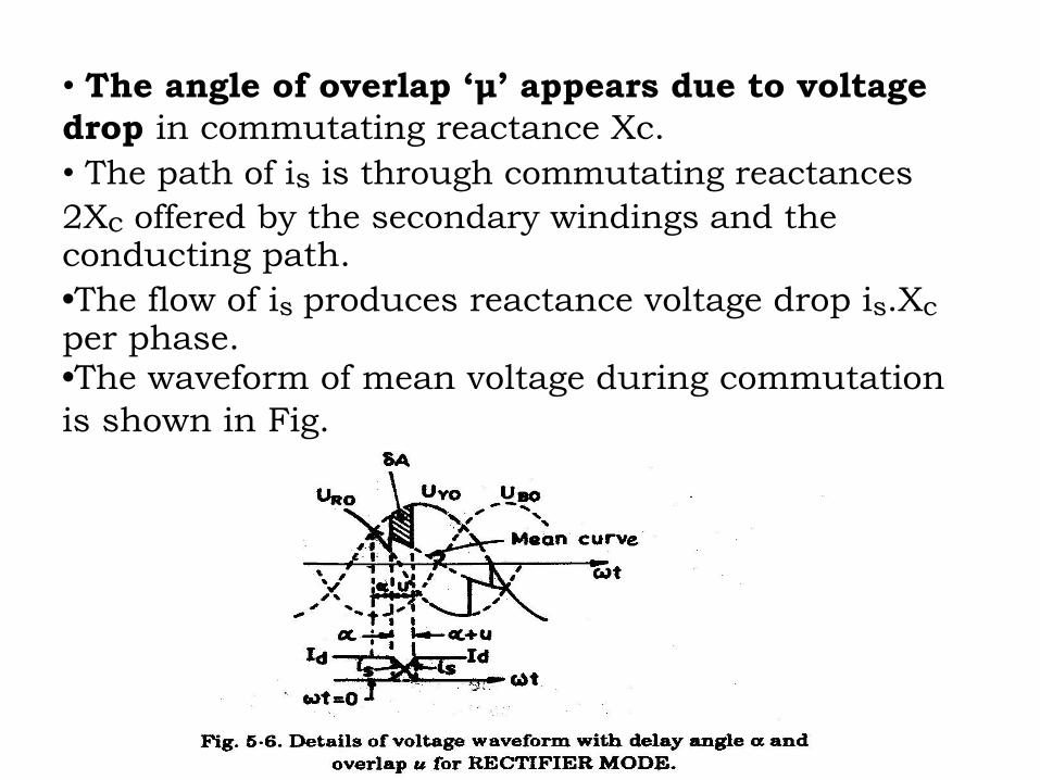
• The angle of overlap ‘μ’ appears due to voltage
drop in commutating reactance Xc. • The path of is is through commutating reactances
2Xc offered by the secondary windings and the conducting path. •The flow of is produces reactance voltage drop is.Xc per phase. •The waveform of mean voltage during commutation
is shown in Fig.

Voltage Equation.
Let vs be the voltage between secondary phases
which is responsible for commutating current is.
Where Usm = peak secondary ph. to ph. voltage
Us = rms, ph. to. ph. secondary voltage
From basic circuit fundamentals, we know
In the local circuit of current is total inductance is
2Lc and current is.
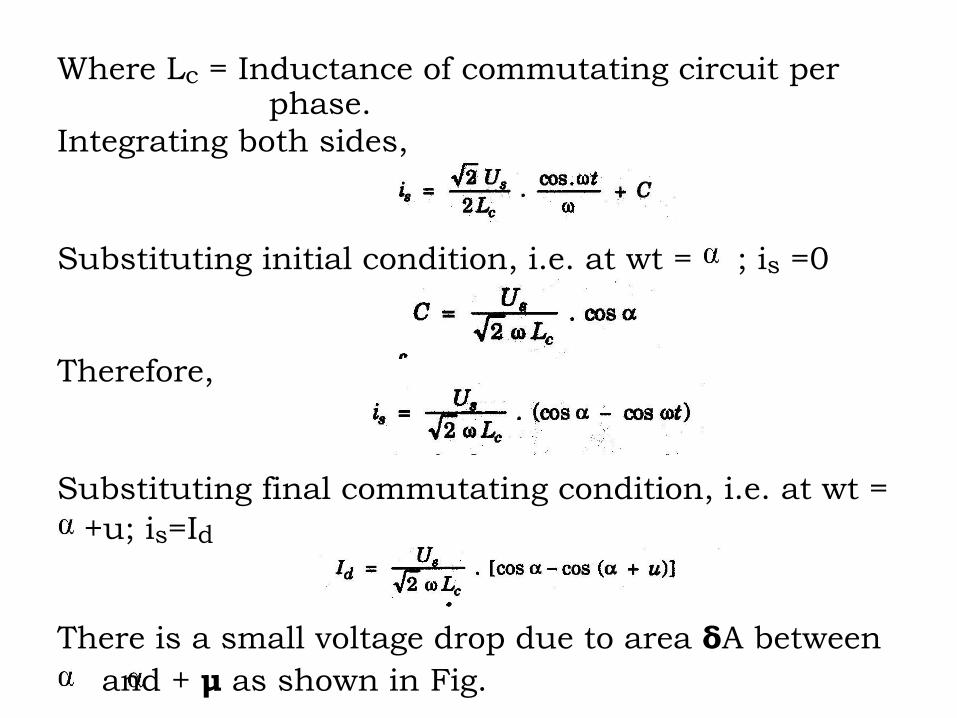
Where Lc = Inductance of commutating circuit per phase.
Integrating both sides,
Substituting initial condition, i.e. at wt = ; is =0
Therefore,
Substituting final commutating condition, i.e. at wt =
+u; is=Id
There is a small voltage drop due to area δA between
and + μ as shown in Fig.

Average value of voltage drop during the period π/3 is

where Udo = No load direct voltage
Ud = Direct voltage on load with delay angle ‘ ’ and overlap angle ‘μ’.
Therefore,

Equivalent Circuit of Rectifier
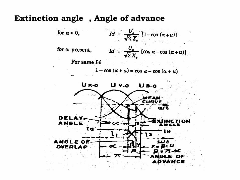
Extinction angle , Angle of advance

Definitions
1. Delay angle . The time expressed in electrical angular measure from zero crossing of idealised sinusoidal commutating voltage to starting instant of forward current. 2. Angle of Advance . Time expressed in electrical angular measure from starting of current to zero crossing of idealised sinusoldal commutating voltage. 3.Relation between and .
4. Angle of overlap u. Time during which two consecutive convertor arms carry current simultaneously. 5. Extinction angle (Margin angle). Time from end of current conduction to zero crossing of idealized commutating sinusoidal voltage. 6. Relationship between , μ, .