department of electrical engineering chalmers university...
TRANSCRIPT
Department of Electrical EngineeringChalmers University of Technology
Subtransmission of electric power to medium sized citiesusing HVDC Light technology
Robert RobinssonArtem Rodionov
Anders Sandström
Technical Report Group A7
Technical Communication FSP025
December 2010

Department of Electrical EngineeringChalmers University of Technology
Subtransmission of electric power to medium sized citiesusing HVDC Light technology
Robert RobinssonArtem Rodionov
Anders Sandström
Department of Electrical EngineeringChalmers University of Technology
Gothenburg, Sweden
Technical Report Group A7
Technical Communication FSP025
December 2010

AbstractElectric power plays an important part in today’s society. To design an electric power system, many things needto be taken into account, such as cost, climate, transmission capacity and environmental issues.
This study examined how a power transmission system for an isolated island with five medium sized citiesmight be designed. After consideration it was found that using HVDC Light power system would be a beneficialsolution in this case. A thoughtful investigation of the fundamental aspects like environmental impact as well ashealth hazards has been carried out to ensure that the solution would be viable in such, or similar environments.A financial aspect was taken into account to ensure that losses of power when transmitting were kept down at areasonable price, without letting the economic aspect gaining too much dominance of the decisions made.
Much of the information regarding the HVDC Light technology was gathered from the manufacturer ABB.This was made because of the technology is still new and only limited amount of information is available fromother sources. IEEE Xplore was used to search for alternative scientific reports to ABB’s database.
i
ContentsAbstract i
1 Introduction 11.1 Problem description . . . . . . . . . . . . . . . . . . . . . . . . . . . . . . . . . . . . . . . . . . 11.2 Background . . . . . . . . . . . . . . . . . . . . . . . . . . . . . . . . . . . . . . . . . . . . . . 11.3 Methods . . . . . . . . . . . . . . . . . . . . . . . . . . . . . . . . . . . . . . . . . . . . . . . . 2
2 Transmission components 32.1 AC or DC . . . . . . . . . . . . . . . . . . . . . . . . . . . . . . . . . . . . . . . . . . . . . . . 32.2 HVDC lines . . . . . . . . . . . . . . . . . . . . . . . . . . . . . . . . . . . . . . . . . . . . . . 3
2.2.1 HVDC Light / HVDC PLUS . . . . . . . . . . . . . . . . . . . . . . . . . . . . . . . . . 32.3 AC lines . . . . . . . . . . . . . . . . . . . . . . . . . . . . . . . . . . . . . . . . . . . . . . . . 42.4 Smart grids . . . . . . . . . . . . . . . . . . . . . . . . . . . . . . . . . . . . . . . . . . . . . . 42.5 Reactive power . . . . . . . . . . . . . . . . . . . . . . . . . . . . . . . . . . . . . . . . . . . . 42.6 The corona effect . . . . . . . . . . . . . . . . . . . . . . . . . . . . . . . . . . . . . . . . . . . 52.7 Circuit Breakers and Lightning protectors . . . . . . . . . . . . . . . . . . . . . . . . . . . . . . 52.8 Transformers . . . . . . . . . . . . . . . . . . . . . . . . . . . . . . . . . . . . . . . . . . . . . 62.9 Overhead transmission/underground transmission . . . . . . . . . . . . . . . . . . . . . . . . . . 72.10 Tower design . . . . . . . . . . . . . . . . . . . . . . . . . . . . . . . . . . . . . . . . . . . . . 72.11 Conductor dimensions . . . . . . . . . . . . . . . . . . . . . . . . . . . . . . . . . . . . . . . . 7
2.11.1 Conductors . . . . . . . . . . . . . . . . . . . . . . . . . . . . . . . . . . . . . . . . . . 82.12 Insulators . . . . . . . . . . . . . . . . . . . . . . . . . . . . . . . . . . . . . . . . . . . . . . . 102.13 Submarine stretching . . . . . . . . . . . . . . . . . . . . . . . . . . . . . . . . . . . . . . . . . 10
2.13.1 Transition section . . . . . . . . . . . . . . . . . . . . . . . . . . . . . . . . . . . . . . . 102.14 Electric and electromagnetic fields . . . . . . . . . . . . . . . . . . . . . . . . . . . . . . . . . . 112.15 Future expansion . . . . . . . . . . . . . . . . . . . . . . . . . . . . . . . . . . . . . . . . . . . 112.16 Line corridors . . . . . . . . . . . . . . . . . . . . . . . . . . . . . . . . . . . . . . . . . . . . . 11
2.16.1 Maintenance . . . . . . . . . . . . . . . . . . . . . . . . . . . . . . . . . . . . . . . . . 11
3 Conclusion 13
A Appended Chapter 16A.1 Cables . . . . . . . . . . . . . . . . . . . . . . . . . . . . . . . . . . . . . . . . . . . . . . . . . 16
List of Figures1 Map of the island . . . . . . . . . . . . . . . . . . . . . . . . . . . . . . . . . . . . . . . . . . . 12 A schematic of a bipolar HVDC-system (Wikipedia) . . . . . . . . . . . . . . . . . . . . . . . . 33 Suggested design of a HVDC tower (Minnesota Electric Transmission Planning) . . . . . . . . . 74 Map of the study’s focus area (Explanation is given in section 2.15) . . . . . . . . . . . . . . . . 95 The electric field around cable bundle with three cables . . . . . . . . . . . . . . . . . . . . . . . 96 Line 6 . . . . . . . . . . . . . . . . . . . . . . . . . . . . . . . . . . . . . . . . . . . . . . . . . 10
List of Tables1 Table of cables . . . . . . . . . . . . . . . . . . . . . . . . . . . . . . . . . . . . . . . . . . . . 82 Cables . . . . . . . . . . . . . . . . . . . . . . . . . . . . . . . . . . . . . . . . . . . . . . . . . 16
ii
1 Introduction
1.1 Problem descriptionWhen designing a power transmission system, many natural phenomena and technical solutions need to be con-sidered. Aspects such as economy, environmental issues, efficiency, health and safety are highly prioritized, andpartly contradict each other, thus making such a project a series of complex decision making and consideration.
1.2 BackgroundThe task is to design a functional power system with all its components. Every component in the system has tobe dimensioned after the demand and possible growth of demand. Environmental issues should also be taken intoaccount, as well as economy.
On an island there are a couple of cities that need a new power transmission designed for their needs, such asindustrial and commercial use of electric power. The island has two main power sources - one fossil power plant,that is supposed to supply about 25 percent of the total energy, and one power plant that is fueled by renewablesources that are supposed to supply the remaining 75 percent of the total demand.
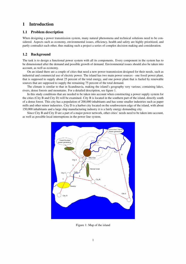
The climate is similar to that in Scandinavia, making the island’s geography very various; containing lakes,rivers, dense forests and mountains. For a detailed description, see figure 1.
In this study conditions that are needed to be taken into account when constructing a power supply system forthe cities (City B and City D) will be examined. City B is located in the southern part of the island, directly southof a dense forest. This city has a population of 200,000 inhabitants and has some smaller industries such as papermills and other minor industries. City D is a harbor city located on the southwestern edge of the island, with about150,000 inhabitants and a large ship manufacturing industry it is a fairly energy demanding city.
Since City B and City D are a part of a major power network, other cities’ needs need to be taken into account,as well as possible local interruptions in the power line system.
Figure 1: Map of the island
1
1.3 MethodsTo solve this kind of problem a literature study has been undertaken to ensure that the methods are modern,efficient, environmentally friendly and realistic.
A market study has been performed too, to see that there are products on the market that are useable for suchan energy system, within reasonable cost margins.
These kinds of investigations are very case specific and there is no universal solution that could be applied inany case, therefore a case study is required, to ensure the best solution in every case.
2
2 Transmission components
2.1 AC or DCThe first and main question that is to be solved is whether AC or DC should be used when transmitting power inthis case. AC is traditionally used for long distance transmission but new DC transmission technologies (HVDC)are now available on the market and have their benefits and drawbacks.
High voltages are used in power transmission because it makes the losses lower. Since the current for a givenamount of power is in inverse proportion to the voltage, losses will be reduced to 1/4 each time the voltage isdoubled, as can be deduced from the formula:
P = RI2
2.2 HVDC linesHVDC is a fairly new technology. Over long distances, HVDC has lower losses than AC, and the cost of the lineitself is reduced because it needs less conductors. It is advantageous for long undersea cables, where AC can notbe used because of high capacitance of the cable. Another common application of HVDC is interconnection ofunsynchronized AC grids, sometimes even grids with different frequencies. This can not be directly accomplishedwith AC. However, since DC cannot be used in traditional transformers, expensive converter stations are neededthat uses modern power electronics to change voltage levels and convert it back into AC for commercial use. Thecost of converter stations is high, and they also introduce losses, which mean that for short to medium distances,the total cost and losses for a HVDC line may be higher than an equivalent AC line. (High voltage direct current,archived version 24/9/2010)
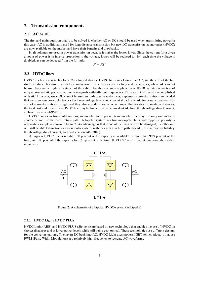
HVDC comes in two configurations, monopolar and bipolar. A monopolar line may use only one metallicconductor and use the earth return path. A bipolar system has two monopolar lines with opposite polarity, aschematic example is shown in figure 2. An advantage is that if one of the lines were to be damaged, the other onewill still be able to function as a monopolar system, with the earth as return path instead. This increases reliability.(High voltage direct current, archived version 24/9/2010)
A bi-polar HVDC line is reliable. 50 percent of the capacity is available for more than 99.9 percent of thetime, and 100 percent of the capacity for 97.0 percent of the time. (HVDC Classic reliability and availability, dateunknown)
Figure 2: A schematic of a bipolar HVDC-system (Wikipedia)
2.2.1 HVDC Light / HVDC PLUS
HVDC Light (ABB) and HVDC PLUS (Siemens) are based on new technology that enables the use of HVDC onshorter distances and at lower power levels while still being economical. These technologies use different designsfor the converter stations. To convert DC back into AC, HVDC Light uses modern IGBT semiconductors that usePWM (Pulse Width Modulation) at a relatively high frequency to recreate AC waveforms.
3

2.3 AC linesAC transmission is on the other hand an old technology that is widely spread in the world. Its benefits are that thevoltages can be more easily transformed up, for long distance transmission. Thus making AC more beneficial onshort to medium distances.
In this specific case, there are no long range-distances that would be especially suitable for the use of HVDCpower lines as City B is located around 150 km from City C and City D is approximately 160 km from City C.HVDC is usually used when there are only two connections between which a current is transported because fortaking out power from a HVDC power line, an electronic converter station is needed. For being able to connectmore cities with HVDC lines, such a station will be needed in each city where power is taken.
However, modern research states that more and more of the conventional power in the future will be suppliedby DC. For example when making smart grids stable, it is easier to control using DC power than AC power, sincewhen using AC power frequency and voltage need to be considered, while in a DC line the main concern is voltage.(Smart grid thinking, date unknown) The voltage for this case should be ±320 kV in a bipolar configuration (320kV between a live conductor and ground). This is the highest currently available voltage for HVDC systems basedon VSC technology. Because of the high voltage, large clearance distances are needed but the transmission losseswill be lower. The total land area needed for the line is still smaller than an AC system with the same voltage andpower. (It’s time to connect - Technical description of HVDC Light technology, March 2008)
Typical losses for electricity transmission and distribution are 6-8 percent. (Energy efficiency in the powergrid, 2007)
2.4 Smart gridsPeople and industries all around the world consume a great deal of energy. This has created a demand for steadyand safe power sources. Smart grids have been developed to solve this problem. Smart grids are transmissionsystems where the energy can be monitored and regulated to suit the actual energy need.
The energy available from renewable sources for example: wind, solar and tidal power, is intermittent. Becauseof the difficulties in storing large amounts of electricity, this makes it necessary to have backup capacity available,which is often fueled by fossil fuels. If consumers, both residential and industrial, had a way of knowing thecondition of the power grid in near real-time, devices could be made to switch on and off automatically dependingon how much available energy there is. For example, the thermostat in a heating or cooling system could be madeslightly less or more likely to turn on and off. Advanced electric meters can encourage consumers to use lessenergy during high load periods by charging a premium price for electricity consumed during those hours.
According to a guide "What is a smart grid", a large number of such devices, they would all work together inmatching the load on the grid to the amount of power available momentarily; meaning that less backup capacityis needed when using intermittent power sources, resulting in more efficient use of energy and lower emissions.Additionally, unlike traditional grids where power generation is centralized and the grid is designed to transmitpower in only one direction, smart grids have better ability to integrate local small-scale generation. (What is asmart grid 9th October 2010)
2.5 Reactive powerReactive power is something that is needed to be taken into account when building a power grid. Some loads areinductive or capacitive, for example electric motors. The inductive or capacitive part (known as the reactive part)of a load does not consume real power, but still draw current. This is caused by the phase shift between the voltageand current waveforms. When a curve for the power (P=U*I) is plotted, part of the curve will be therefore be onthe negative side. This is because in the power (for the reactive part) is not actually consumed, it is only absorbedand then returned to the grid every for every half-cycle. The current for a reactive load that flows through thecables and transformers however is real, and should be minimized since it does not actually transfer real powerbut would uncorrected take up a significant part of the transmission capacity of the infrastructure as well as causeresistive loss of power. (Lessons In Electric Circuits – Volume II Chapter 11 POWER FACTOR, unknown date).
In practice, most reactive loads are inductive. The phase shift caused by them can be corrected by connectingcapacitors to the power grid. This will cause a phase shift in the other direction, thereby reducing the currentdrawn. For capacitive loads, equivalent correction can be achieved by the use of inductors. The amount of com-pensation needed varies because the total load varies. Compensation capacitors are therefore often switchable. Itis common that the compensation takes place close to the consumers (devices still need reactive power), so that
4
the reactive power flow further up in the distribution and transmission network is minimized. Without compensa-tion, the voltage the consumer will vary if the reactive load varies. (Grisby, L (2007), Electric Power Generation,transmission and distribution).
For example, if a factory consumes 150 kW, with a lagging power factor of 0.75, the apparent power neededto be supplied is 200 kVA (150/0.75), which would need a current of 20 A if fed by 10,000 V (single phase). Byadding capacitance in parallel with the supply lines close to the factory, generating the reactive power on site, thecurrent can be lowered. The reactance of the capacitor bank should be:
Xc =V 2
Q=
100002 V
132000 V AR= 758 Ω
Giving a value of:
C =1
2Π ∗ fXc=
1
2Π ∗ 50 Hz ∗ 758 Ω= 4.2 µF
This would result in a PF close to 1, which would make the line resonant which is unwanted. Therefore aslightly lower capacitance value should be used. If the power factor were to be corrected to 0.9, the current thatwould need to be transmitted is only 16.7 A (167 kVA/10 kV), meaning smaller distribution transformers andthinner wire can be used, or that the same equipment is able to transmit more useful power.
A common type of compensator is an SVC, Static VAR Compensators. This type uses (fixed, switchable ora combination of) capacitors and inductors connected in parallel with the power grid. (It’s time to connect withoffshore wind supplement, April 2010)
For HVDC Light, each converter station also functions as an SVC at the same time. The system gives goodand fast control over reactive power flow, with the ability to control active and reactive power independently. Ittherefore also gives good control over the voltage variations caused by reactive power. (It’s time to connect withoffshore wind supplement, April 2010).
2.6 The corona effectLonger stretches of transmission lines demand higher voltages to function efficiently. The high voltage may causecorona discharges along the line. A corona discharge is a natural phenomenon caused by the ionization of the fluidor gas around the conductor. When this occurs conductive plasma is formed at the area around the discharge.
It is important to avoid corona discharges, otherwise the efficiency of the power line will drop because of elec-tric current leaking out into the conductive plasma created by the corona discharge. The risk of corona dischargeincreases during certain environmental conditions. Rain for example will make it easier for the corona dischargeto form.
Corona discharges can create sounds, electromagnetic interference and ozone production around itself thatcan disturb the surrounding area. The discharge may also damage the line and its components. There are waysto prevent corona discharges to occur, for example with special conductors. But these modifications are veryexpensive. The power line is for that reason constructed to be fairly corona free during normal weather. Thebest way to prevent discharges is to choose a conductor were the electric field is minimal on the surface of theconductor.
Corona discharges occur when the electric field strength exceeds 3kV/mm along a power line suspended in theair and 20kV/mm if an XLPE insulated underground cable is used. Since electric field strength is a vector, thuswhen placing three cables in a triangle with a common radius, some parts of the electric fields will be cancelledout making the total area of where a corona discharge may occur smaller. For an illustration, see figure 5.
2.7 Circuit Breakers and Lightning protectorsTo prevent damage from overload or short circuit, automatically-operated switches are normally used to cut thepower. The circuit breakers are made to switch off the power when some sort of problem is detected along thepower line. The advantage of using circuit breakers instead of fuses is that fuses only function once and then haveto be replaced. Unlike the circuit breaker which can be reset manually or automatically.
A lightning protection system is used to protect the power lines from damage caused by lightning. The deviceshould safely lead the high voltage strike pass all critical components to the ground.
5
If lighting were to strike a phase conductor on an overhead power line, the high voltage will cause arcingbetween the wire and ground or another wire. The arc will not extinguish itself because the voltage and currentavailable from the power line is high enough to keep it alive. To stop the arc, the voltage needs to be removedfrom the line by a circuit breaker.
The number of lightning strikes to a conductor can be greatly reduced by adding one or more grounded shieldwires over the other wires. This can reduce the number of flashovers by over 95 percent. The number of wiresdepends on how frequent lighting strikes are in the area (the number of strikes per unit of area varies a lot aroundthe world) and the required reliability. More than necessary shield wires should not be used because it adds to thecost of the line.
In this specific case, because of the climate of the island is similar to that of Sweden, a low to moderate lightingstrike frequency is assumed. Under these conditions, a single shield wire above the conductors provides adequateprotection. (Grisby, L (2007), Electric Power Generation, transmission and distribution).
2.8 TransformersTransformers are used in high-voltage power lines to increase the voltage when transmitting electrical energy overlonger distances. They are also used to decrease the voltage so the power can be delivered to the households.Transformers require AC power. If DC power is used, special converter stations that use power electronics tochange voltage levels must be used.
Transformers transform electric energy from one circuit to another circuit with a different voltage level. Thisis accomplished magnetically by induction. The transformer itself consists of a magnetic core with two or morewindings. Different kind of windings will generate different voltage transformation ratios. Smaller transformerscan be air cooled, but bigger transformers will be warmer during operation and will therefore require better coolingmethods. The transformer can be immersed in mineral oil in order to cool and insulate the transformer.
6
2.9 Overhead transmission/underground transmissionEconomy is one important factor when planning a power grid. The investment cost is the largest part in thebudget. Overhead transmission cables are a lot cheaper then underground transmission cables. The work costis lower when building overhead transmission lines, the construction of the tower is the only complex structureneeded. The conductor can be installed in a few hours. Underground cables on the other side have to be dug downinto the ground. The work is very time consuming when done over longer distances.
The conclusion is that overhead power lines, although exposed to lighting and other environmental factors, area good alternative when constructing longer stretches of transmission lines. For example, if a corona dischargeappears in an XLPE-isolated underground cable, eventually, the cable will fail, unlike a suspended equivalent.
Underground cables can be an alternative in urban areas and where environmental conditions are difficult, suchas under lakes, rivers and where the risk of disturbance is great.
Maintenance will be needed to keep the line functioning. Different types of transmission systems requiredifferent levels of maintenance. Overhead power lines are significantly easier to maintain. Work can even bedone when the power is on, which will drastically decrease the risk of power outages. Underground cables aremore difficult to maintain. The cable need to be dug up in order to perform repairs, often with power outage as aconsequence.
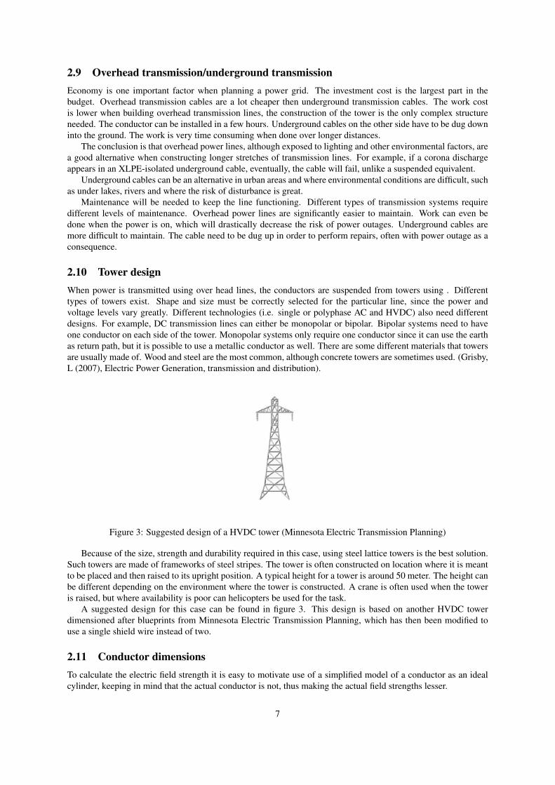
2.10 Tower designWhen power is transmitted using over head lines, the conductors are suspended from towers using . Differenttypes of towers exist. Shape and size must be correctly selected for the particular line, since the power andvoltage levels vary greatly. Different technologies (i.e. single or polyphase AC and HVDC) also need differentdesigns. For example, DC transmission lines can either be monopolar or bipolar. Bipolar systems need to haveone conductor on each side of the tower. Monopolar systems only require one conductor since it can use the earthas return path, but it is possible to use a metallic conductor as well. There are some different materials that towersare usually made of. Wood and steel are the most common, although concrete towers are sometimes used. (Grisby,L (2007), Electric Power Generation, transmission and distribution).
Figure 3: Suggested design of a HVDC tower (Minnesota Electric Transmission Planning)
Because of the size, strength and durability required in this case, using steel lattice towers is the best solution.Such towers are made of frameworks of steel stripes. The tower is often constructed on location where it is meantto be placed and then raised to its upright position. A typical height for a tower is around 50 meter. The height canbe different depending on the environment where the tower is constructed. A crane is often used when the toweris raised, but where availability is poor can helicopters be used for the task.
A suggested design for this case can be found in figure 3. This design is based on another HVDC towerdimensioned after blueprints from Minnesota Electric Transmission Planning, which has then been modified touse a single shield wire instead of two.
2.11 Conductor dimensionsTo calculate the electric field strength it is easy to motivate use of a simplified model of a conductor as an idealcylinder, keeping in mind that the actual conductor is not, thus making the actual field strengths lesser.
7
The formula for calculating the electric field strength of an ideal cylinder is:
E =U
R ∗ Ln(Ry
Ri)
Where U is the voltage of the cable, Ri is the radius of the cable, Ry is the distance to the nearest possiblepoint of discharge and R is the point where E is measured.
In this case:
3 kV/mm =320 kV
Riln( 1800 mmRi
)
Resulting in:Ri = 25 mm
320 kV is the maximum voltage on the cable with respect to ground, and 1800 mm is half the distance to thenearest grounded point (i.e. half the length of the insulators).
2.11.1 Conductors
A conductor is a material in which electrical charges can move. Most conductors are made of metal. The mostused conductor type is made of copper. Silver is a very good conductor, but it is also very impractical to usebecause of its cost.
Aluminum is the most used material when making conductors for high-voltage power lines. It is more con-ductive than copper when it is compared per weight unit. The use of aluminum in household applications hasproven problematic. Thin wires will heat up and expand, frequent expansions can cause a short circuit to occurand increase the risk of potential fires in the application. In heavy duty applications, such as high voltage powertransmission aluminum conductors can be used with good result.
It is easier and thereby more preferable to use overhead transmission lines over underground lines, more aboutthis in section 2.9. The conductor of an overhead line can be made without a protective insulator layer. This willreduce the building and maintenance cost.
The most used conductor is called ACSR (aluminum-conductor-steel-reinforced). It is made of layers ofstranded aluminum; steel is also used in the core to reinforce the conductor further. There are different factors totake into account when choosing conductors. AC or DC transmission systems require different setups of conduc-tors.
AC power transmission requires three conductors to function efficiently. Installation of the extra conductorwill increase the cost. Additional insulators and different towers will be needed.
Two conductors are required to transmit the power in a DC power system. This will decrease the cost of theactual conductor length needed for the line. Two conductors can be hung in smaller towers with fewer insulators.
The size of the conductor is determined by the current going through it. The electric field is proportional tothe conductor diameter. Transmission lines below 230 kV are dimensioned mainly after heat development, theconductor size of lines above 230 kV are mainly defined by the electric field.
Since this system relies on DC power, and the voltage ideally does not vary, inductance and capacitance is notan issue that has to be dealt with, apart from when switching on and off the power, which should in theory nothappen that often.
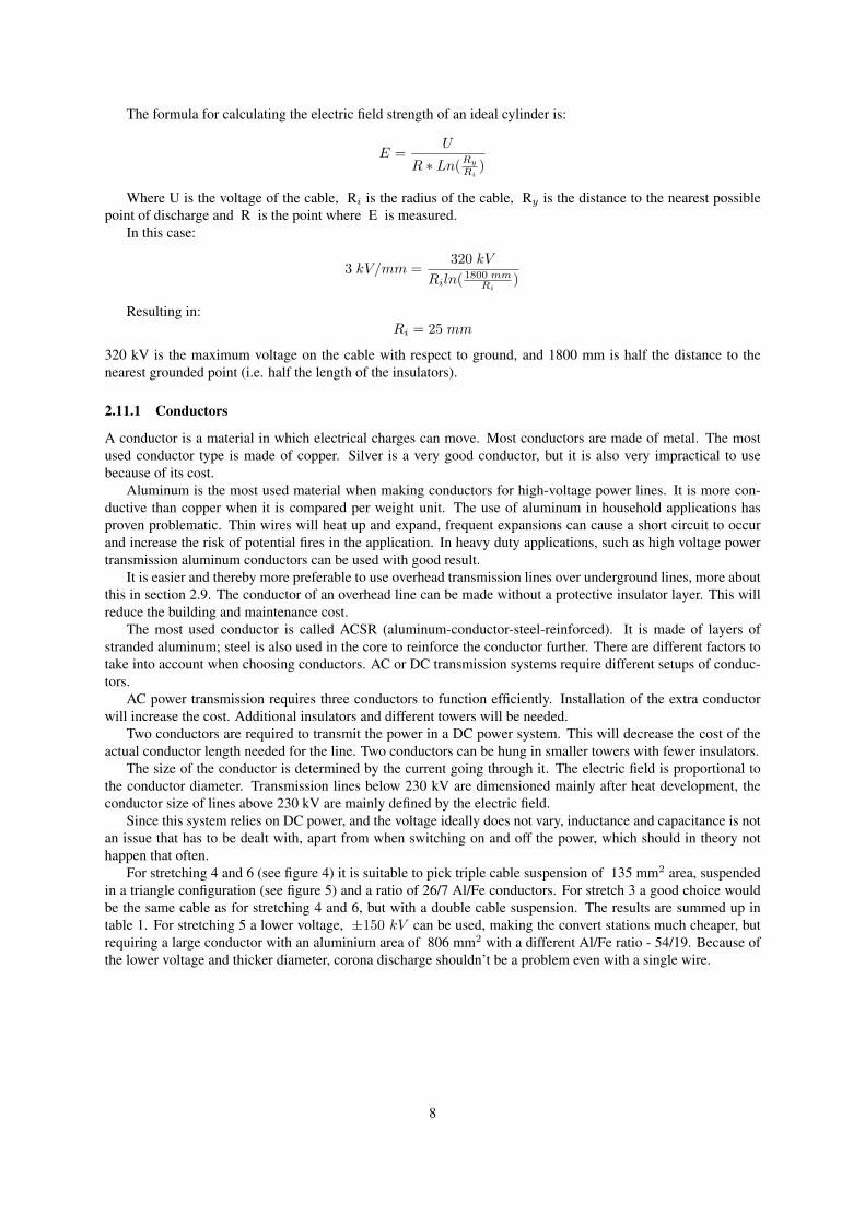
For stretching 4 and 6 (see figure 4) it is suitable to pick triple cable suspension of 135 mm2 area, suspendedin a triangle configuration (see figure 5) and a ratio of 26/7 Al/Fe conductors. For stretch 3 a good choice wouldbe the same cable as for stretching 4 and 6, but with a double cable suspension. The results are summed up intable 1. For stretching 5 a lower voltage, ±150 kV can be used, making the convert stations much cheaper, butrequiring a large conductor with an aluminium area of 806 mm2 with a different Al/Fe ratio - 54/19. Because ofthe lower voltage and thicker diameter, corona discharge shouldn’t be a problem even with a single wire.
8
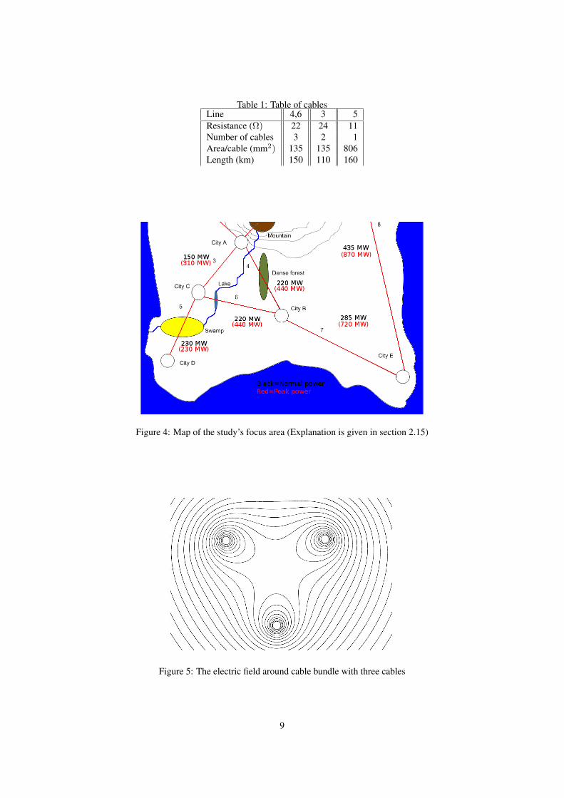
Table 1: Table of cablesLine 4,6 3 5Resistance (Ω) 22 24 11Number of cables 3 2 1Area/cable (mm2) 135 135 806Length (km) 150 110 160
Figure 4: Map of the study’s focus area (Explanation is given in section 2.15)
Figure 5: The electric field around cable bundle with three cables
9
2.12 InsulatorsCommon types of insulators used for insulating power lines are glass, porcelain and composite materials. Glass isa better insulator then the porcelain equivalent, but it is much harder to make glass insulators. It is very difficultto cast glass insulators because of the irregular shape. Glass attracts a lot of condensation to its surface. This willcause current to "leak" into the ground.
A new type of insulator is made of polymer composite materials. They are lightweight and not that costly tomake. Because they are new, they have not been fully tested over longer periods, leaving long term usability inquestion.
According to Grisby’s book Electric Power Generation, it is important that the insulator is dimensioned tosuit the voltage level. The insulator must withstand temporary overvoltage, lightning etc. The weather and en-vironment can reduce the effectiveness of the insulator. Rain and pollution can form a conductive layer on thesurface of the conductor, which may cause current loss and mechanical stresses on the insulator. Wind is anothermajor factor one has to keep in mind when designing the insulator. (Grisby, L (2007), Electric Power Generation,transmission and distribution).
The insulators that high voltage power lines use are made up of several smaller units put together in a string,which is known as a cap and pin insulator. Higher voltages need more units. (Overvoltage and Flashovers, dateunknown).
For a voltage of 320 kV, 24 units are to be used. The total string length is then 3.6 m for a unit length of 15cm.
2.13 Submarine stretching
Figure 6: Line 6
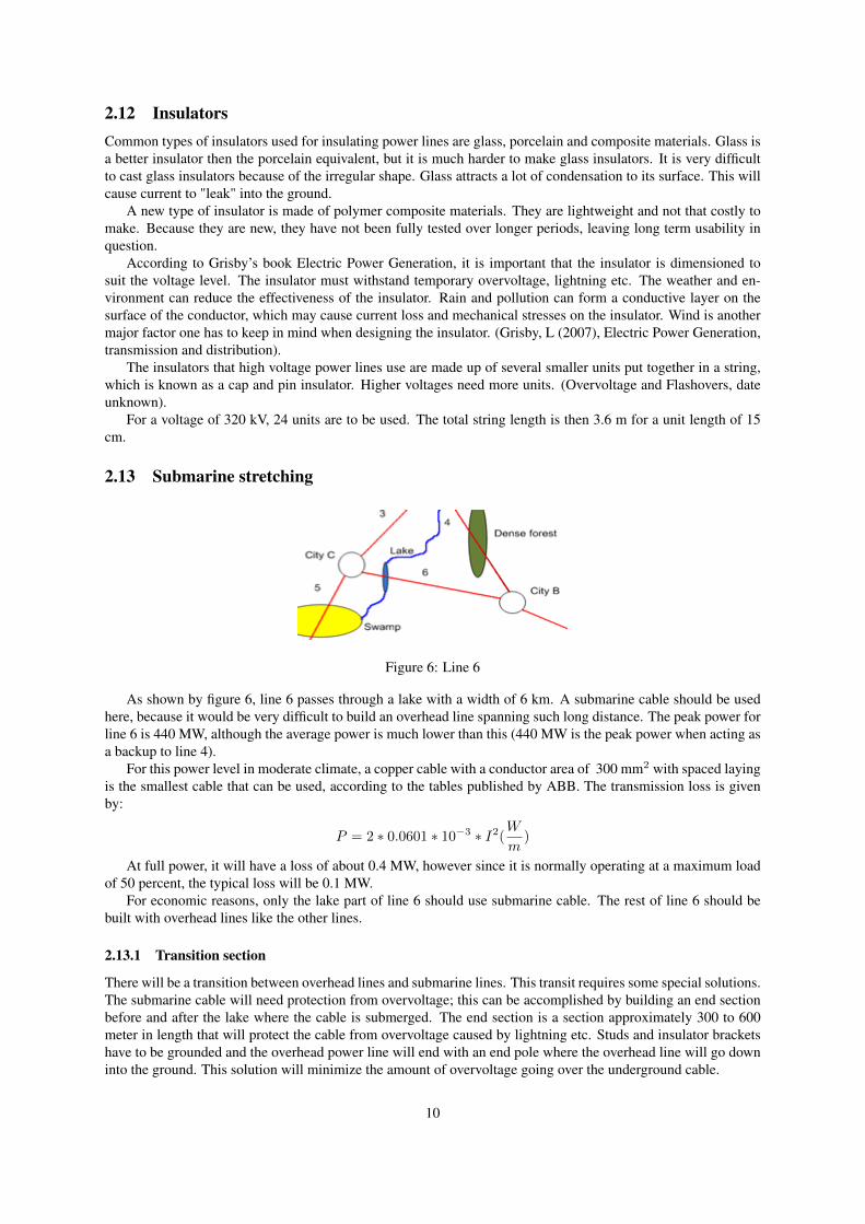
As shown by figure 6, line 6 passes through a lake with a width of 6 km. A submarine cable should be usedhere, because it would be very difficult to build an overhead line spanning such long distance. The peak power forline 6 is 440 MW, although the average power is much lower than this (440 MW is the peak power when acting asa backup to line 4).
For this power level in moderate climate, a copper cable with a conductor area of 300 mm2 with spaced layingis the smallest cable that can be used, according to the tables published by ABB. The transmission loss is givenby:
P = 2 ∗ 0.0601 ∗ 10−3 ∗ I2(W
m)
At full power, it will have a loss of about 0.4 MW, however since it is normally operating at a maximum loadof 50 percent, the typical loss will be 0.1 MW.
For economic reasons, only the lake part of line 6 should use submarine cable. The rest of line 6 should bebuilt with overhead lines like the other lines.
2.13.1 Transition section
There will be a transition between overhead lines and submarine lines. This transit requires some special solutions.The submarine cable will need protection from overvoltage; this can be accomplished by building an end sectionbefore and after the lake where the cable is submerged. The end section is a section approximately 300 to 600meter in length that will protect the cable from overvoltage caused by lightning etc. Studs and insulator bracketshave to be grounded and the overhead power line will end with an end pole where the overhead line will go downinto the ground. This solution will minimize the amount of overvoltage going over the underground cable.
10
2.14 Electric and electromagnetic fieldsThere are limits to the magnetic and electric field strength that must be taken into account, because such fieldsmight have negative health effects. For DC, the magnetic field strength should not exceed 21 200 µT and theelectric field should be no stronger than 20 kV/m. For safety reasons, these limits are conservative (Dr. MichaelHausler, 1997). The limits are much higher for DC than for AC, because the field is static and not alternating it isassumed to be safer than the fields generated from AC transmission lines.
In similar cases using the about same tower dimensions and voltage levels, electric field strengths are at mostabout 20 kV/m (Dr. Michael Hausler, 1997).
The strength of the magnetic field around a conductor is given by:
B = µ0I
2Πr
Where µ0 is a constant that equals to 4Π ∗ 10−7 , and r is the distance from the center of the conductor. Thisequation gives a magnetic field strength of 60 µT around a conductor carrying 1500 A at a radius of 5 m. Thisvalue doesn’t take into account that it will partly be cancelled by the opposite current flow in the other conductor,but it is still several orders of magnitude lower than the limit value.
2.15 Future expansionThe capacity of the power line is over dimensioned to handle possible power failures along the transmission line.The cities will probably expand their power consumption in the future, because of population growth. Sweden canbe seen as a good comparison to the island in question with similar social structures and development index. Ac-cording to Statistics Sweden, Sweden’s annual population growth is expected to be about 1.03 percent. (Sverigesbefolkningsutveckling - från 1.7 till 9 miljoner, 19th February 2008).
It is very important when building a new line to estimate the future expansion of the cities, so the line can bedimensioned after that. It will otherwise be very costly to upgrade or totally rebuild the transmission line in thefuture. It is better to invest heavily now rather than doing smaller investments over longer time.
The numbers in red in figure 4 show the estimates of expected power transmitted during a power outage.Because over dimensioning is needed to ensure the possibility of backup power in case of transmission failure ofone line, this also will ensure that there is sufficient transmission capacity during normal circumstances for futuredemand growth. The conductor dimensions satisfying these requirements are presented in the appended chapterA.1.
2.16 Line corridorsWhen building an overhead transmission line, a line corridor through areas with dense vegetation is needed. TheSwedish standards for such line corridors are 34 to 44 meters, since the environment on the island is similar tothe Nordic climate, it would be suitable to use this standard. Because the island has a climate similar to that ofSweden, it is justified to assume that the major parts of the stretch of the power line will be through forest.
2.16.1 Maintenance
A line corridor is easier to maintain the closer it is to an urban area. This is due to the possibility of makingbuilding restrictions around power lines and the fact that the landowners in those areas tend to maintain their trees.The infrastructure around urban areas is also denser making 12-24-month inspections economically efficient.
According to the study "Evaluation of Areal Remote Sensing Techniques", the problems with maintenanceincrease with the distance to the urban areas. The access is limited because of the distance and the inspectionshave to be extended as far as once every five years apart. The maintenance consists of two visits; the first visit isfor spotting problem areas and the second being the actual maintenance. When doing so, there are two possibleways of spotting the problem areas - either through driving or walking through the terrain or by flying with ahelicopter above it. Neither of these methods is economically efficient - the first method taking many man hoursthat need to be paid and the second being faster, but the equipment, the helicopter and the operator being thehigh costs instead. (Evaluation of Aerial Remote Sensing Techniques for Vegetation Management in Power-LineCorridors September 2010)
11
Some of the main problems using airborne technologies for detecting vegetation that is threatening the powerline are the detection of trees, and the algorithm that analyzes the image data should not respond on tree’s shadows.Another problem that needs be taken into the account is the measurement of the tree’s position with the respectto the power line, both the height of the tree is needed to be measured and the tree’s position perpendicular tothe power line’s stretching. In the study mentioned above (Evaluation of Aerial Remote Sensing Techniques forVegetation Management in Power-Line Corridors September 2010); as a complement to the image processingtechnology, a radar technology, LiDAR is used.
The equipment of the aircraft performing these measurements needs to be precise enough to detect tree limbsthat could threaten the power line, not only tree crowns. There is an automatic detection technology that has beendeveloped for measuring and detecting trees from an aircraft, using image processing. Its successful detectionrate is about 96 percent. The main concern of this measurement algorithm is not the multiple trees that might beidentified as one single, but rather the trees that are missed by the algorithm and are interpreted as ground. Thismaking the correct detection rate to yield about 75 percent. While the geographic measurements with help of GPSand other optical instruments yield and accuracy rate of 95 percent, making this not a concern.
The height detection is made by using the radar and the image processing technology placed on the airplaneat the same time, making these technologies overlap each other. The detection rate of each of the systems amountto over 95 percent, with the image technology being inferior to the radar system, when estimating the height, butmaking it a good complement for detecting trees, to ensure a lower percentage of not found trees. The averageerror of the radar system when measuring height was less than 1 meter. (Evaluation of Aerial Remote SensingTechniques for Vegetation Management in Power-Line Corridors September 2010)
All in all, the tree detection systems are reliable when detecting trees and, to some point, when it comes todetermination of their heights. One major disadvantage is that the radar analysis is manually performed, makingthis time consuming. However, there are already existing algorithms that could be developed for the automation ofthis process. It should be kept in mind that when mentioning a success rate of 98 percent in this case, could meanhundreds or thousands of missing potential threats when scanning a forest. However, if considering the possibilityof making the controls, for example two times a year along each power line, this could intensify the control rateup to 10 times, compared to once every five years, making such an investigation more up to date than a manuallymade control.
12
3 Conclusion• A possible power transmission system for an island with a few cities has been presented in this study. It was
found that a bipolar HVDC Light-based system using ±320 kV with overhead lines is a viable option, withmany advantages over an equivalent AC system, such as smaller towers and line corridors, better controlover power flow, safer electromagnetic fields and perhaps most importantly, better integration of intermittentpower sources. However, it does need a larger initial investment.
• The use of overhead lines have been chosen rather than underground cables to reduce the cost, as well asmaking maintenance easier compared to underground power lines. It is, although the problems with over-head line maintenance in distant areas, cheaper to maintain and repair an overhead line than an undergroundequivalent.
• The lake in the path of line 6 is too wide for a conventional overhead line, making a submarine cablerequired. Since it is a submarine cable it is dug in the lakebed to avoid damage from anchors and vegetation.
• Dimensioning of the different system components (insulators, conductors, etc) has been presented. Calcu-lations were done to keep losses at low levels, avoiding problems caused by corona discharge and makingsure that the power lines do not have the potential to cause health problems for nearby people and animals,and do not put vegetation at risk.
• To make a power efficient power network a smart grid should be implemented, that has smart meters wherethe power is consumed and has the ability to enable local small-scale generation to be integrated efficiently.
13
References
Chen, W-K : The Electrical Engineering Handbook, Elsevier Academic Press, 2005.
Dr. Michael Hausler, Gernot Schlayer : Converting AC power lines to DC for higher transmissionratings. , ABB, 1997.
Grisby, L : Electric Power Generation, transmission and distribution, CRC Press, 2007.
Henrik Stomberg, Jan Lundquist : Summary of costs for overhead lines and cables in the region, STRI, 2008.
http://www.pa.msu.edu/courses/1997spring/phy232/lectures/ampereslaw/wire.html : Elementary Physics, Michigan State University, 20/10/2010.
http://www.antonine-education.co.uk/physics_a2/module_4/topic_9/topic_9.htm : Electric Fields, Antonine Education, 20/10/2010.
http://www.iea.lth.se/et/G4_05.pdf : Kraftledningar, LTH, 24/9/2010.
http://www05.abb.com/global/scot/scot271.nsf/veritydisplay/8345ed00181dda7bc1256ecc0034c069/File/04-1120ENG209703.pdf : PDF, ABB,10/9/2010.
http://en.wikipedia.org/w/index.php?title=High-voltage_direct_current&oldid=386623544 : High-voltage direct current, Wikipedia, 24/9/2010.
http://www.abb.com/industries/ap/db0003db004333/eb8b4075fb41252ec12574aa00409424.aspx : Unknown, ABB, 9/24/2010.
http://en.wikipedia.org/wiki/File:Hvdc_bipolar_schematic.svg : Hvdc bipolarschematic, Wikipedia, 24/9/2010.
http://www.abb.com/cawp/seitp202/3e22c0f632c49999c125755800491d81.aspx :Smart grid thinking, ABB, 9/24/2010.
http://search-ext.abb.com/library/Download.aspx?DocumentID=1JNL100105-122&LanguageCode=en&DocumentPartID=&Action=Launch : It’s time toconnect, ABB, 01/10/2010.
http://www02.abb.com/global/seitp/seitp202.nsf/c71c66c1f02e6575c125711f004660e6/64cee3203250d1b7c12572c8003b2b48/FILE/Energy+efficiency+in+the+power+grid.pdf : Unknown, ABB, 01/10/2010.
http://ieeexplore.ieee.org/stamp/stamp.jsp?tp=&arnumber=5466249 : Evalu-ation of Aerial Remote Sensing Techniques for Vegetation Management in Power-Line Corridors, IEEE,27/10/2010.
http://www.ibiblio.org/kuphaldt/electricCircuits/AC/AC_11.html : LessonsIn Electric Circuits – Volume II Chapter 11 POWER FACTOR,Ibiblio, 08/10/2010.
http://www05.abb.com/global/scot/scot221.nsf/veritydisplay/fb4d15b402dc68c7c12577210040f853/Filje/Pow003820R620LR.pdf : Unknown, ABB,11/10/2010.
http://www.minnelectrans.com/transmission-system.html : How the electric trans-
14

mission system works, Minnesota Electric Transmission Planning, 11/10/2010.
http://www.smartmeters.com/faqs/56-smartmeters-101/1245-what-is-a-smart-grid.html : What is a smart grid?, Smartmeters, 03/11/2010.
http://www05.abb.com/global/scot/scot245.nsf/veritydisplay/1591f139098f62e5c1257154002f9801/File/HVDC20Light20power20cables.pdf :HVDC Light cables, ABB, 20/10/2010.
http://ieeexplore.ieee.org/stamp/stamp.jsp?tp=&arnumber=5466249 : Evalu-ation of Aerial Remote Sensing Techniques for Vegetation Management in Power-Line Corridors, IEEE,27/10/2010.
http://www.myinsulators.com/acw/bookref/overvoltage/index.html : Over-voltage and Flashovers, MyInsulators, 09/11/2010.
http://www.scb.se/Pages/TableAndChart____224772.aspx : Sveriges befolkning-sutveckling - från 1,7 till 9 miljoner, Statistics Sweden, 23/11/2010.
15

A Appended Chapter
A.1 Cables
Table 2: CablesLine Peak power (MW) Peak current (A) Area (mm2)1 300 500 3002 870 1440 8003 310 514 1854 440 730 4055 230 813 5006 440 730 4057 720 1195 6308 870 1440 1000
Current calculated by Ohm’s law + 6 percent.
16