department of electronics and communication engineering...
TRANSCRIPT

Department of Electronics and Communication Engineering
National Institute of Technology, Rourkela
Odisha, India- 769008
Final Year Thesis on
“QUADROTOR”
A detailed Analysis on Construction and Operation
(Under the supervision of
Prof S.K Patra, Dept of ECE)
Submitted by:
Prannoy Ray- 110EI0252
Moti Prakash Panda- 110EI0247

A Thesis submitted in partial fulfillment of the requirements for the degree of
Bachelor of Technology
In
Electronics and Instrumantation Engineering
By
Prannoy Ray
Roll No.: 110EI0252
Moti Prakash Panda
Roll No.: 110EI0247
Under the Guidance of
Prof. S. K. Patra
Department of Electronics and Communication Engineering
National Institute of Technology
Rourkela-769008 (ODISHA)
MAY 2014
DEPARTMENT OF ELECTRONICS AND COMMUNICATION ENGG,
NATIONAL INSTITUTE OF TECHNOLOGY, ROURKELA- 769 008
ODISHA, INDIA
This is to certify that the thesis entitled “Quadrotor: A detailed Analysis”, submitted to
the National Institute of Technology, Rourkela by Prannoy Ray, Roll No. 110EI0252 and
Moti Prakash Panda, Roll No. 110EI02 for the award of the degree of Bachelor of
Technology in Department of Electronics and Communication Engineering, is a bonafide
record of research work carried out by them under my supervision and guidance.
The candidate has fulfilled all the prescribed requirements. The thesis is based on candidate’s
own work, is not submitted elsewhere for the award of degree/diploma.
In my opinion, the thesis is in standard fulfilling all the requirements for the award of the degree
of Bachelor of Technology in Electronics and Communication Engineering.
Prof. S K Patra
Supervisor
Department of Electronics and Communication Engineering
National Institute of Technology-Rourkela,
Odisha– 769008 (INDIA)
CERTIFICATE

01. ACKNOWLEDGEMENT
We would like to convey our deepest gratitude towards our supervisor, Professor S. K. Patra for
his support and supervision, and for the valuable knowledge that he shared with us.
We would like to thank Mr. Pallav Majhi, our friends and seniors who have helped us to
complete the thesis work successfully.
We would like to convey appreciation to our family members, for their encouragement and
support.
We thank God for being on our side.
Prannoy Ray
Moti Prakash Panda
02. Abstract
It is a type of an unmanned air vehicle (UAV) which by its name suggests that consists of 4
engines to drive it. Usually we use BLDC motors and propellers as the engines of a quad. Its
motion and dynamics can be compared with that of a helicopter in regards to its transverse and
longitudinal motion. It has various uses in various fields of military, business, rescue mission,
modern warfare etc. They have a vertical take-off and landing system. Unlike a helicopter the
propellers or blades of a “Quadrotor” have fixed pitch.
Control of vehicle motion is achieved by altering the pitch and/or rotation rate of one or more
rotor discs, thereby changing its torque load and thrust/lift characteristics. This will be explained
in details in course of the following discussion. If we look into history of the “Quadrotor”, we
get to know that it was the first step towards vertical take-off and landing vehicle. At first it was
a manned vehicle but now mainly the research is focused upon a unmanned “Quadrotor” which
is controlled with the help of electronic signals and various other mechanisms.
03. Keywords
Quad-Rotor
Aerodynamics
Propellers Design and Payload
Arduino Due- Microcontroller
X-Bee wireless Module
Stable Flight
Air Density
Implementation

04. TABLE OF CONTENTS
Sl. No. Topic
1. Acknowledgement
2. Abstract
3. Keyword
4. Table of Contents
5. Problem statement
6. Introduction
7. Concept design and details
8. Design details
9. List of components required
10. Working and specification
11. Programming and controlling
12. Analysis and Optimization of time of flight
13. Areas of Implementation
14. Conclusion
15. Reference

06 .PROBLEM STATEMENT:
To design and manufacture a “Quadrotor” which can be used for aerial surveillance.
To study the various areas of implementation of “Quadrotor” and its development.
Mechanical Design Implementation target:
It should be cheap and should be light weight
It should be able to carry a load i.e. Payload of around 2kgs
Maximum time of flight
Automated Design Implementation target:
Should be controlled by laptop/computer so that Quadrotor could receive
movement orders from a ground station wirelessly.
Fitted with camera(for still images and video), should transfer snapped data to
the laptop/computer on ground for “LIVE telemetry data”
Should balance on its own in case of turbulence.
6.1 Thesis Contribution
The thesis would focus on the design details of the Quadrotor and then slowly move on to the
programming details of the Arduino and XBEE pair and their required configuration. Apart from
that, the thesis would also involve optimisation of Flight time by taking into consideration air
density, temperature and humidity of the environment and the altitude of the place. Effective
design of propellers is also dealt minutely for more efficient power utilisation by minimising
speed of motor. Thus the thesis would be better described as an overall view of how a Quadrotor
works and its potential in the near future, construction details and areas of research for
commercial production and use. The Thesis in total would cover all the possible and potential
areas of Quadrotor construction and its engineering beauty.

07. INTRODUCTION
7.1 Definition and purpose of a Quadrotor
A “Quadrotor”, also called a quadrotor helicopter, It is a multicopter that is lifted and
propelled by four rotors.
“Quadrotors” are classified as rotorcraft, as opposed to fixed-wing aircraft, because
their lift is generated by a set of revolving narrow-chord airfoils. Unlike most helicopters,
“Quadrotors” generally use symmetrically pitched blades; these can be adjusted as a group, a
property known as 'collective', but not individually based upon the blade's position in the rotor
disc, which is called 'cyclic' Control of vehicle. Motion is achieved by altering the pitch and/or
rotation rate of one or more rotor discs, thereby changing its torque load and thrust/lift
characteristics.
7.2 Quadrotor Operation
(More recently “Quadrotor” designs have become popular in unmanned aerial vehicle (UAV)
research. These vehicles use an electronic control system and electronic sensors to stabilize
the aircraft. With their small size and agile manoeuvrability, these “Quadrotors” can be flown
indoors as well as outdoors.)There are several advantages to “Quadrotor”s over comparably-
scaled helicopters. First, “Quadrotors” do not require mechanical linkages to vary the rotor
blade pitch angle as they spin. This simplifies the design and maintenance of the vehicle.
Second, the use of four rotors allows each individual rotor to have a smaller diameter than the
equivalent helicopter rotor, allowing them to possess less kinetic energy during flight. This
reduces the damage caused should the rotors hit anything. For small-scale UAVs, this makes
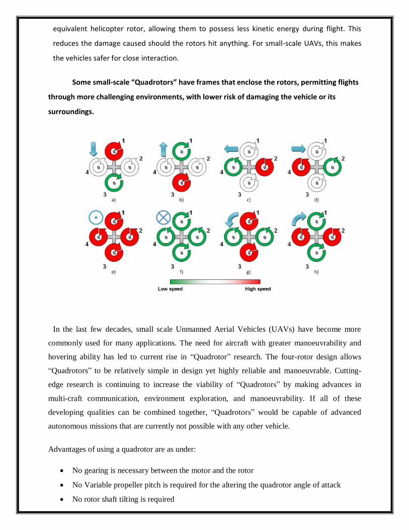
the vehicles safer for close interaction.
Some small-scale “Quadrotors” have frames that enclose the rotors, permitting flights
through more challenging environments, with lower risk of damaging the vehicle or its
surroundings.
In the last few decades, small scale Unmanned Aerial Vehicles (UAVs) have become more
commonly used for many applications. The need for aircraft with greater manoeuvrability and
hovering ability has led to current rise in “Quadrotor” research. The four-rotor design allows
“Quadrotors” to be relatively simple in design yet highly reliable and manoeuvrable. Cutting-
edge research is continuing to increase the viability of “Quadrotors” by making advances in
multi-craft communication, environment exploration, and manoeuvrability. If all of these
developing qualities can be combined together, “Quadrotors” would be capable of advanced
autonomous missions that are currently not possible with any other vehicle.
Advantages of using a quadrotor are as under:
No gearing is necessary between the motor and the rotor
No Variable propeller pitch is required for the altering the quadrotor angle of attack
No rotor shaft tilting is required

4 small motors instead of one big rotor resulting in less stored kinetic energy and thus
less damage in case of accidents
Minimal mechanical complexity
Quadrotors require less maintenance compared to both helicopters and planes
Rotor Mechanics simplification
Payload augmentation
Gyroscopic effects reduction
Using GPS for waypoint tracking and altitude, on-board camera and a dual processor
capable of autonomous path navigation and data exchange with the ground station. PID
controllers each to control pitch, roll, yaw and throttle and their respective gains, can be used to
stabilize the system.
Although there are the drawbacks of weight augmentation and high energy consumption,
these can be reduced using efficient energy sources and materials engineering research.

08. CONCEPT DESIGN AND DETAILS
8.1 Mechanical Mechanism:-
The torque produced in the adjacent motors rotate in different configurations for example if
motor 1 and 3 rotate clockwise than motor 2 and 4 will rotate anticlockwise but producing the
same thrust and torque due to equal angular velocity. We use pusher and puller propellers
which have configurations so as to produce an upward thrust rotating in clockwise and
anticlockwise directions respectively.
Since a quadrotor has a fixed pitch and so it moves forward by change in the angular
velocity of its motors. Differential thrust between opposite motors provides roll and pitch
torques. Differential thrust between the two pairs of counter-rotating motors provides yaw
torque.
The modelling of quadrotor can be done with the help of non linear dynamics.. Let {eN, eE,
eD} denote unit vectors along the respective inertial axes, and {xB, yB, zB} denote unit vectors
along the respective body axes, as defined in Figure (Free body diagram of a quadrotor). The
roll, pitch and yaw angles are controlled by differential thrust. Position control, with respect to
the frame is accomplished by controlling the magnitude and direction of the total thrust. A drag
force, Db, also acts on the vehicle, opposite the velocity direction, eV.
Below is given the free body diagram which explains the inertial system clearly and
different forces on the quad rotor.
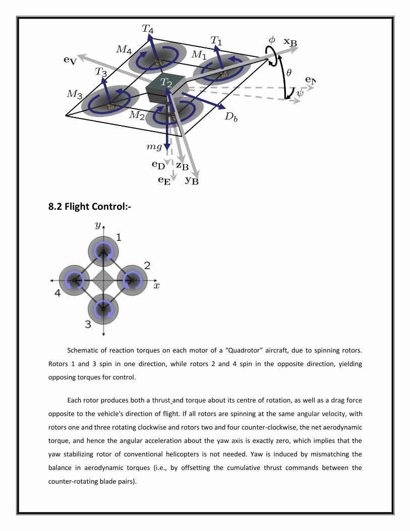
8.2 Flight Control:-
Schematic of reaction torques on each motor of a “Quadrotor” aircraft, due to spinning rotors.
Rotors 1 and 3 spin in one direction, while rotors 2 and 4 spin in the opposite direction, yielding
opposing torques for control.
Each rotor produces both a thrust and torque about its centre of rotation, as well as a drag force
opposite to the vehicle's direction of flight. If all rotors are spinning at the same angular velocity, with
rotors one and three rotating clockwise and rotors two and four counter-clockwise, the net aerodynamic
torque, and hence the angular acceleration about the yaw axis is exactly zero, which implies that the
yaw stabilizing rotor of conventional helicopters is not needed. Yaw is induced by mismatching the
balance in aerodynamic torques (i.e., by offsetting the cumulative thrust commands between the
counter-rotating blade pairs).

Angular accelerations about the pitch and roll axes can be caused separately without affecting the
yaw axis. Each pair of blades rotating in the same direction controls one axis, either roll or pitch, and
increasing thrust for one rotor while decreasing thrust for the other will maintain the torque balance
needed for yaw stability and induce a net torque about the roll or pitch axes. This way, fixed rotor
blades can be made to manoeuvre the quadrotor in all dimensions. Translational acceleration is
achieved by maintaining a non-zero pitch or roll angle.
Four rotors are used, rather than three, six or some other number, because four offers two
convenient axes of symmetry. With four rotors it is easy to imbalance side-to-side thrust, thus giving a
roll movement. As this pair of side rotors rotate in the same direction, and one is increased whilst the
other is decreased, the overall torque reaction and yawing force remains zero. A similar geometry
applies to controlling pitch, using the fore-and-aft rotor pair. The “Quadrotor” design remains inherently
in balance for yaw, even as the primary control inputs are changed, thus is easier to learn to fly. In
practice, high-end “Quadrotors” today also use on-board gyroscopes to stabilize yaw more precisely.
“Quadrotors” may use either the 'diamond' or 'square' layouts of their rotors. The diamond
pattern is slightly easier to understand, as each control axis relies on a single pair of rotors and the
others are unaffected. With the addition of a simple control mixer though, the square pattern operates
just as easily. Like the V Tail of some fixed-wing aircraft, movements of pure pitch or pure roll then rely
on a combined input to the two diagonal axes.
Although quadrotor vehicle dynamics are often assumed to be accurately modelled as linear for
attitude and altitude control, this assumption is only reasonable at slow velocities. Even at moderate
velocities, the impact of the aerodynamic effects resulting from variation in air speed is significant.
There are mainly three effects known as total thrust, blade flapping and airflow disruptions. Firstly the
total thrust varies not only with the power input but also with the free stream velocity but also
the angle of attack with respect to the free stream. The second effect results from differing
inflow velocities experienced by the advancing and retreating blades. This leads to “blade
flapping” which induces roll and pitch moments on the rotor hub as well as deflection of the
thrust vector. The third effect is the interference caused by the vehicle body in slip stream of
the rotor. It results in unsteady thrust behaviour rendering attitude control difficult.
The dynamic analysis becomes more complex when we calculate different parameters
affecting the motion of a quadrotor. We are here focusing on the fabrication of an
automated Quadrotor used for surveillance so we haven’t included other complex analysis
and have thus avoided the details.

(The above figures indicate rotational and transitional motion of the quadrotor, respectively based on
differential torques exerted by the rotation of motors.)
09. DESIGN DETAILS
The main mechanical components needed for construction are the frame, propellers (either fixed-
pitch or variable-pitch), and the electric motors. For best performance and simplest control algorithms,
the motors and propellers should be placed equidistant. Recently, carbon fibre composites have become
popular due to their light weight and structural stiffness.
The electrical components needed to construct a working “Quadrotor” are similar to those
needed for a modern RC helicopter. They are the Electronic Speed Control module, on-board computer
or controller board, and battery. Typically, a hobby remote control is also used to allow for human input.
“Quadrotors” and other multicopters also often have the ability of autonomous flight. Many modern
Flight Controllers use software that allows the user to mark "way-points" on a map and then have their
“Quadrotor” fly to those locations and perform tasks such as landing or gaining altitude.
09.1 Design selection:
Concept 1- This design has 4 arms made up of pvc pipes. These are light weight materials and
are cheap and easily available.
Concept 2- This design has 4 pair of thin arms made up of carbon fibre/polyamide nylon(with
brass lining) which is very light and strong to crashes but is costly.
Concept 3- This design has rotating bldc motors for manoeuvring the “Quadrotor”. But its
skeleton has flat shaped rods, which leads to air drag.
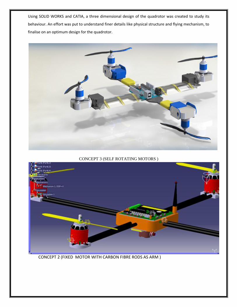
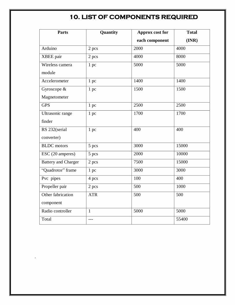
Using SOLID WORKS and CATIA, a three dimensional design of the quadrotor was created to study its
behaviour. An effort was put to understand finer details like physical structure and flying mechanism, to
finalise on an optimum design for the quadrotor.
CONCEPT 3 (SELF ROTATING MOTORS )
CONCEPT 2 (FIXED MOTOR WITH CARBON FIBRE RODS AS ARM )

CONCEPT 1 (FIXED MOTOR WITH PVC PIPE AS ARM)
We would design our model using Concept-1 or Concept-2.
Concept 2 would be a better option since the construction of the base frame would be hefty
and yet not as strong and light as carbon fibre rod.
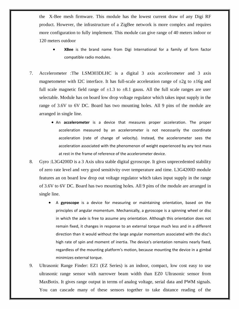
10. LIST OF COMPONENTS REQUIRED
Parts Quantity Approx cost for
each component
Total
(INR)
Arduino 2 pcs 2000 4000
XBEE pair 2 pcs 4000 8000
Wireless camera
module
1 pc 5000 5000
Accelerometer 1 pc 1400 1400
Gyroscope &
Magnetometer
1 pc 1500 1500
GPS 1 pc 2500 2500
Ultrasonic range
finder
1 pc 1700 1700
RS 232(serial
converter)
1 pc 400 400
BLDC motors 5 pcs 3000 15000
ESC (20 amperes) 5 pcs 2000 10000
Battery and Charger 2 pcs 7500 15000
“Quadrotor” frame 1 pc 3000 3000
Pvc pipes 4 pcs 100 400
Propeller pair 2 pcs 500 1000
Other fabrication
component
ATR 500
500
Radio controller 1 5000 5000
Total --- 55400
.

11. WORKING AND SPECIFICATIONS:
1. N2836, 1500Kv Brushless DC Out runner Motor: - This sturdy size 2836, 1500kv BLDC
motor gives maximum thrust of 1200gms and weights only 78gms. It comes with propeller
mount with 5mm diameter.
(The term outrunner refers to a type of brushless motor primarily used in electrically
propelled, radio-controlled model aircraft. Outrunners spin much slower than their
inrunner counterparts with their more traditional layout (though still considerably faster
than ferrite motors) while producing far more torque. This makes an outrunner an excellent
choice for directly driving electric aircraft propellers since they eliminate the extra weight,
complexity, inefficiency and noise of a gearbox.)
2. 20Amp BLDC ESC: -This is fully programmable 20A BLDC ESC with 5V, 2A BEC. Can
drive motors with continuous 20Amp load current. It has sturdy construction with heatsank
on the MOSFETs for better heat dissipation. Its weight is 22 gms and size is 47mm x
27mm x 12mm.Max Speed: 2 Pole: 210,000rpm; 6 Pole: 70,000rpm; 12 Pole: 35,000rpm.
An electronic speed control or ESC is an electronic circuit with the purpose to vary an
electric motor's speed, its direction and possibly also to act as a dynamic brake. ESCs are
often used on electrically powered radio controlled models, with the variety most often
used for brushless motors essentially providing an electronically-generated three phase
electric power low voltage source of energy for the motor.
Output: 20A continuous; 25Amps for 10 seconds
Input voltage: 2-4 cells Lithium Polymer / Lithium Ion battery or 5-12 cells NiMH
/ NiCd
BEC: 5V, 2Amp for external receiver and servos
3. Propeller :-10inch (25cm) diameter 4.5inch (11cm) pitch matched pair of pusher and puller
propellers. Comes with adaptor for 3mm, 3.2mm, 4mm, 5mm, 6mm, 6.35mm, 7.95mm
diameter shaft. It is most suitable for Quadrotors.
A propeller is a type of fan that transmits power by converting rotational motion into
thrust. A pressure difference is produced between the forward and rear surfaces of the
airfoil-shaped blade, and a fluid (such as air or water) is accelerated behind the blade.
4. Frame:- This is a 49.5cm diameter Quadrotor frame with power tracks on PCB for directly
connecting ESCs to Battery. Arms are made up of ultra durable polyamide nylon. Arms

have brass inserts with M3 screw threads. Arms can survive repeated crashes without
breaking.
5. Arduino – AVR 328 Series of microcontroller which has several features of PWM, Timers,
USART, I2C enabling a secure communication to the laptops and other devices. These are
reliable, ultra lightweight and low power consumption devices. Atmega series of
controllers offer onboard programming facility through which instantaneously programs
can be erased and rewritten.
Arduino is a single-board microcontroller to make using electronics in multidisciplinary
projects more accessible. The hardware consists of a simple open-source hardware board
designed around an 8-bit Atmel AVR microcontroller, or a 32-bit Atmel ARM. The software
consists of a standard programming language compiler and a boot loader that executes on
the microcontroller.
6. X-bee: XBee (S2) 2mw XBee ZB (a.k.a. Series 2) module is used for embedded solutions
providing wireless end-point connectivity to devices. This module incorporates the ZigBee
PRO Feature with Set mesh networking protocol. Series 2 modules allow you to create
complex mesh networks, it does not offer any 802.15.4-only firmware; it is always running
the X-Bee mesh firmware. This module has the lowest current draw of any Digi RF
product. However, the infrastructure of a ZigBee network is more complex and requires
more configuration to fully implement. This module can give range of 40 meters indoor or
120 meters outdoor
XBee is the brand name from Digi International for a family of form factor
compatible radio modules.
7. Accelerometer :The LSM303DLHC is a digital 3 axis accelerometer and 3 axis
magnetometer with I2C interface. It has full-scale acceleration range of ±2g to ±16g and
full scale magnetic field range of ±1.3 to ±8.1 gauss. All the full scale ranges are user
selectable. Module has on board low drop voltage regulator which takes input supply in the
range of 3.6V to 6V DC. Board has two mounting holes. All 9 pins of the module are
arranged in single line.
An accelerometer is a device that measures proper acceleration. The proper
acceleration measured by an accelerometer is not necessarily the coordinate
acceleration (rate of change of velocity). Instead, the accelerometer sees the
acceleration associated with the phenomenon of weight experienced by any test mass
at rest in the frame of reference of the accelerometer device.
8. Gyro :L3G4200D is a 3 Axis ultra stable digital gyroscope. It gives unprecedented stability
of zero rate level and very good sensitivity over temperature and time. L3G4200D module
features an on board low drop out voltage regulator which takes input supply in the range
of 3.6V to 6V DC. Board has two mounting holes. All 9 pins of the module are arranged in
single line.
A gyroscope is a device for measuring or maintaining orientation, based on the
principles of angular momentum. Mechanically, a gyroscope is a spinning wheel or disc
in which the axle is free to assume any orientation. Although this orientation does not
remain fixed, it changes in response to an external torque much less and in a different
direction than it would without the large angular momentum associated with the disc's
high rate of spin and moment of inertia. The device's orientation remains nearly fixed,
regardless of the mounting platform's motion, because mounting the device in a gimbal
minimizes external torque.
9. Ultrasonic Range Finder: EZ1 (EZ Series) is an indoor, compact, low cost easy to use
ultrasonic range sensor with narrower beam width than EZ0 Ultrasonic sensor from
MaxBotix. It gives range output in terms of analog voltage, serial data and PWM signals.
You can cascade many of these sensors together to take distance reading of the
surrounding area without any interference from the adjacent sensor.It detects objects from
15cm to 645 cm (6 inches to 254 inches) with the resolution of 2.5cm (1 inch). It gives
range output in the Analog, Pulse Width Modulation (PWM) and in the serial format which
makes it very convenient for interfacing.
Ultrasonic sensors (also known as transceivers when they both send and receive, but
more generally called transducers) work on a principle similar to radar or sonar which
evaluate attributes of a target by interpreting the echoes from radio or sound waves
respectively. Ultrasonic sensors generate high frequency sound waves and evaluate the
echo which is received back by the sensor. Sensors calculate the time interval between
sending the signal and receiving the echo to determine the distance to an object.
10. GPS: -GPS Receiver MT3318 Module from NEX Robotics is based on the SiRF Star III
technology. GPS module has on-board compact Ceramic GPS patch antenna. The receiver
module can track 20 satellites simultaneously. GPS receiver updates navigation data every
second. It gives data output is in standard NMEA information format at the baud rate of
9600bps.
The Global Positioning System (GPS) is a space-based satellite navigation system that
provides location and time information in all weather conditions, anywhere on or near
the Earth where there is an unobstructed line of sight to four or more GPS satellites.
11. Camera: -Wireless Small size spy camera for Surveillance and robotics. The very small
size and low power operation makes it useful for mounting on wireless robots to transmit
the video to receiver. The received signal can then be directly seen in to tv or in pc through
TV Tuner or Video Capture Card. For Laptops USB TV Tuners can be used.
12. Battery: -This is high performance 3 Cell, 11.1V, 5000mAh, 30C Battery. It can give
discharge current of 150000Amps. It has ‘T’ type Power connector and 4 pin JS connector.

12. PROGRAMMING AND CONTROLLING
How is wireless communication realised in a quadrotor? Starting from controlling of quadrotor
to data transfer, telemetry transfer, plotting graphs etc. To answer that we must go in a sequence
to cover all the minute details of the communication.
A C++ running in a laptop accessing the open CV library files takes the input from the keyboard
as character datatype. Character is converted to binary data type and serial port of the laptop is
enabled. 8 bit data is converted to 10 bit data and a start bit is sent to the microcontroller. The
micro controller after receiving start bit sends back the feedback bit after which the data is
transferred. The various sensor data sent from the microcontroller to the laptop using open CV
source can plot data using images sent by the camera using a different protocol.
An FTI RS232 chip is connected to the USB port of microcontroller which converts the CMOS
level to TTL level. The serial data is then sent to X-BEE wireless module which is 128 bit
encrypted and uses a secure 8 channel connection with the host station.
The data is received by a mobile X-BEE module which decodes the data, converts it to TTL level
and sends to the microcontroller. Depending upon the key strokes given, the RPM of BLDC
motor is controlled by generating PWM. Timers and interrupters enable an 8 bit pulse which is
sent to the ESC controlling the BLDC motor electronically at a constant RPM. The
microcontroller has 328 kb of memory on which a pre-programmed path can be saved and the
quadrotor can be automated.
GPS device installed gives the global coordinates at 9600 band rate which help in tracking as
well as guiding the “Quadrotor” on a planned mission. The “Quadrotor” is gyro stabilized by use
of a gyro sensor using I2C interfacing. With this it gives the exact angular acceleration in 3 axes
which helps in stabilizing the “Quadrotor” in mid-air. An accelerometer and magnetometer help
in finding the direction as well as guiding the quad rotor when GPS is not working. Autopilot
feature can also be enabled by use of different codes after the fabrication of the basic model.

The Above mentioned data is jotted down to the flow diagram below for better reference.
The quadrotor can be controlled via a romote comtroller using RF techniques or via Laptop
attached to a XBEE Wireless Module via a Serial Converter.
Now going into details of each of the component, we start with XBEE Wireless Module.
12.1 Our Model used for the project is “XBEE Pro” wireless module. The system data flow
diagram is as below:
The Laptop here acts as the microcontroller (as in the above diagram), thus receiving all the data
and can frame the data into a graph when required. In order to connect the XBEE to the laptop
we need a USB to Serial Converter i.e RS232. The RS232 formally defines the signals
connecting between a DTE(Data Terminal Equipment) and a DCE (data circuit-terminating
equipment) such as a modem. Commonly used in computer serial ports, this is used here in order
to connect the XBEE module to the Laptop via USB.
12.1.1 XBEE Design Notes:
Minimum connections: VCC, GND, DOUT & DIN Minimum connections to support serial firmware upgrades: VCC, GND, DIN, DOUT, RTS
& DTR Signal Direction is specified with respect to the module Module includes a 30k Ohm resistor attached to RESET
Several of the input pull-ups can be configured using the PR command Unused pins should be left disconnected Pin 20 can be connected to a push button (pin grounded when closed) to support the
commissioning push button functionality.
12.1.2 Modes of Operation :
Idle Mode (When not receiving or transmitting data, the RF module is in Idle Mode)
Transmit Mode (Serial data in the serial receive buffer is ready to be packetized)
Receive Mode (Valid RF data is received through the antenna)
Sleep Mode (End Devices only)
Command Mode (Command Mode Sequence is issued)
12.1.3 The XBEE internal Design :

12.1.4 Specifications of XBEE pins:
12.1.5 Electrical Characterstics of XBEE:
Apart from that, in order to use XBEE with any microcontroller, we need to reconfigure the
default settings in order to match with the type of micro-controller used. The Reconfiguration
programme for XBEE is dumped into it via the RS232 USB to Serial Converter using the
“CODE BLOCKS software” which is a open C++ platform for programming.
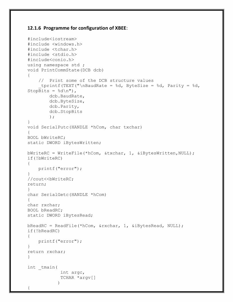
12.1.6 Programme for configuration of XBEE:
#include<iostream>
#include <windows.h>
#include <tchar.h>
#include <stdio.h>
#include<conio.h>
using namespace std ;
void PrintCommState(DCB dcb)
{
// Print some of the DCB structure values
_tprintf(TEXT("\nBaudRate = %d, ByteSize = %d, Parity = %d,
StopBits = %d\n"),
dcb.BaudRate,
dcb.ByteSize,
dcb.Parity,
dcb.StopBits
);
}
void SerialPutc(HANDLE *hCom, char txchar)
{
BOOL bWriteRC;
static DWORD iBytesWritten;
bWriteRC = WriteFile(*hCom, &txchar, 1, &iBytesWritten,NULL);
if(!bWriteRC)
{
printf("error");
}
//cout<<bWriteRC;
return;
}
char SerialGetc(HANDLE *hCom)
{
char rxchar;
BOOL bReadRC;
static DWORD iBytesRead;
bReadRC = ReadFile(*hCom, &rxchar, 1, &iBytesRead, NULL);
if(!bReadRC)
{
printf("error");
}
return rxchar;
}
int _tmain(
int argc,
TCHAR *argv[]
)
{
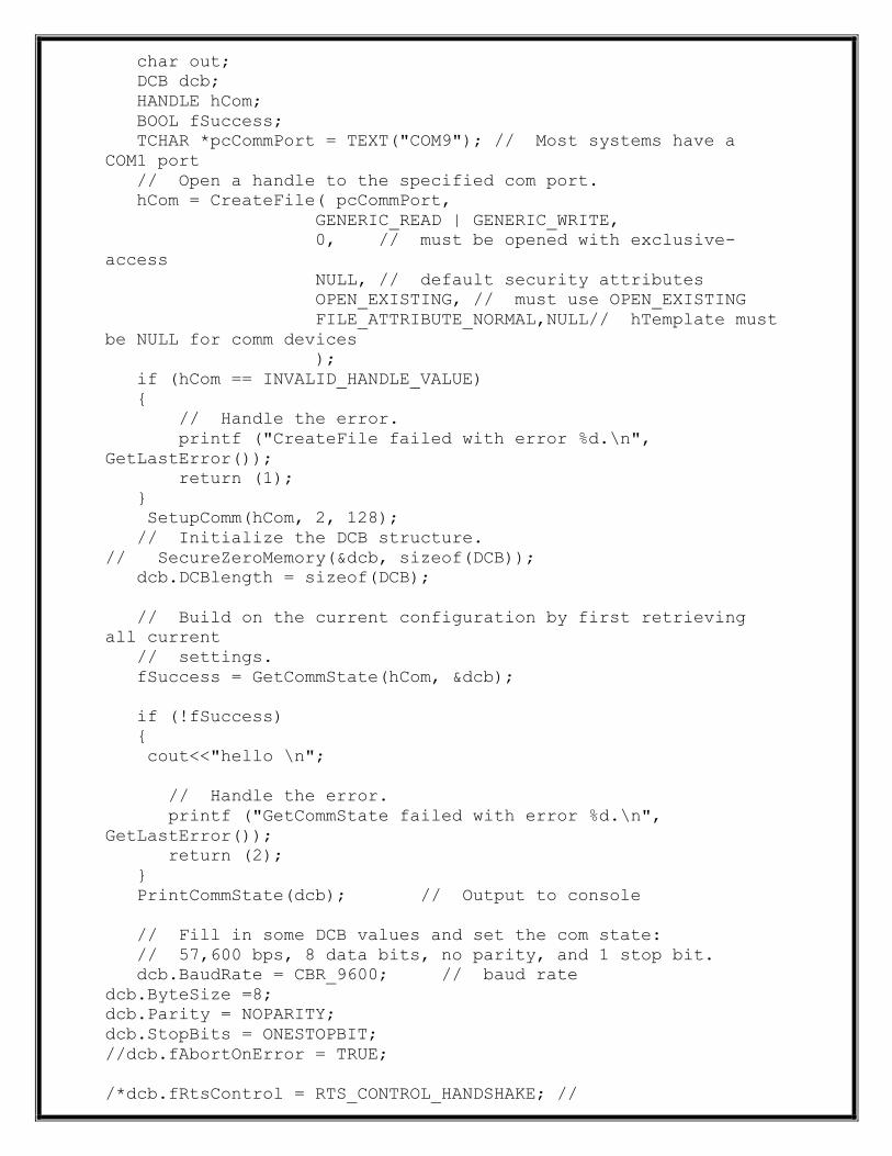
char out;
DCB dcb;
HANDLE hCom;
BOOL fSuccess;
TCHAR *pcCommPort = TEXT("COM9"); // Most systems have a
COM1 port
// Open a handle to the specified com port.
hCom = CreateFile( pcCommPort,
GENERIC_READ | GENERIC_WRITE,
0, // must be opened with exclusive-
access
NULL, // default security attributes
OPEN_EXISTING, // must use OPEN_EXISTING
FILE_ATTRIBUTE_NORMAL,NULL// hTemplate must
be NULL for comm devices
);
if (hCom == INVALID_HANDLE_VALUE)
{
// Handle the error.
printf ("CreateFile failed with error %d.\n",
GetLastError());
return (1);
}
SetupComm(hCom, 2, 128);
// Initialize the DCB structure.
// SecureZeroMemory(&dcb, sizeof(DCB));
dcb.DCBlength = sizeof(DCB);
// Build on the current configuration by first retrieving
all current
// settings.
fSuccess = GetCommState(hCom, &dcb);
if (!fSuccess)
{
cout<<"hello \n";
// Handle the error.
printf ("GetCommState failed with error %d.\n",
GetLastError());
return (2);
}
PrintCommState(dcb); // Output to console
// Fill in some DCB values and set the com state:
// 57,600 bps, 8 data bits, no parity, and 1 stop bit.
dcb.BaudRate = CBR_9600; // baud rate
dcb.ByteSize =8;
dcb.Parity = NOPARITY;
dcb.StopBits = ONESTOPBIT;
//dcb.fAbortOnError = TRUE;
/*dcb.fRtsControl = RTS_CONTROL_HANDSHAKE; //

// set DSRDTR
dcb.fOutxDsrFlow = FALSE; // turn on DSR flow control
dcb.fDtrControl = DTR_CONTROL_ENABLE; //*/
fSuccess = SetCommState(hCom, &dcb);
if (!fSuccess)
{
// Handle the error.
printf ("SetCommState failed with error %d.\n",
GetLastError());
return (3);
}
// Get the comm config again.
fSuccess = GetCommState(hCom, &dcb);
if (!fSuccess)
{
// Handle the error.
printf ("GetCommState failed with error %d.\n",
GetLastError());
return (2);
}
PrintCommState(dcb); // Output to console
/*COMMTIMEOUTS CommTimeouts;
GetCommTimeouts (hCom, &CommTimeouts);
CommTimeouts.ReadIntervalTimeout = 5000;
CommTimeouts.ReadTotalTimeoutConstant = 5000;
CommTimeouts.ReadTotalTimeoutMultiplier = 1000;
CommTimeouts.WriteTotalTimeoutConstant = 5000;
CommTimeouts.WriteTotalTimeoutMultiplier = 1000;
SetCommTimeouts (hCom, &CommTimeouts);
PrintCommState(dcb);*/
char txchar;
int x;
HANDLE *ptr=&hCom;
while(1)
{Sleep(10);
printf("hello \n ");
x=SerialGetc(ptr);
// scanf("%c",&out);
//txchar=getch();
//txchar=SerialGetc(ptr);
SerialPutc(ptr,'u');
//printf("%c",txchar);
//if(!bWriteRC)
printf ("%d \n ",x);
//cout<<iBytesWritten;
}
_tprintf (TEXT("Serial port %s successfully
reconfigured.\n"), pcCommPort);

return (0);
}
12.2 ARDUINO: Model Used is “ARDUINO DUE”
The Arduino Due is a microcontroller board based on the Atmel SAM3X8E ARM Cortex-M3
CPU. It is the first Arduino board based on a 32-bit ARM core microcontroller. It has 54 digital
input/output pins (of which 12 can be used as PWM outputs), 12 analog inputs, 4 UARTs
(hardware serial ports), a 84 MHz clock, an USB OTG capable connection, 2 DAC (digital to
analog), 2 TWI, a power jack, an SPI header, a JTAG header, a reset button and an erase button.
Unlike other Arduino boards, the Arduino Due board runs at 3.3V. The maximum voltage that
the I/O pins can tolerate is 3.3V. Providing higher voltages, like 5V to an I/O pin could damage
the board.
The board contains everything needed to support the microcontroller; simply connect it to a
computer with a micro-USB cable or power it with a AC-to-DC adapter or battery to get started.
The Due is compatible with all Arduino shields that work at 3.3V and are compliant with the 1.0
Arduino pinout.
The Due follows the 1.0 pinout:
TWI: SDA and SCL pins that are near to the AREF pin.
The IOREF pin which allows an attached shield with the proper configuration to adapt to
the voltage provided by the board. This enables shield compatibility with a 3.3V board
like the Due and AVR-based boards which operate at 5V.
An unconnected pin, reserved for future use.

12.2.1 Pin Configuration on Arduino Due Board is as under:

After successful completion of the wiring of the Arduino Board and the XBEE module with
the laptop and RS232 Serial converter, the Controlling of quadrotor via the arrow
switches, is done by the following program.
09.2.2 Program
#include "opencv/cv.h"
#include "opencv/highgui.h"
#include<iostream>
#include <windows.h>
#include <tchar.h>
#include <stdio.h>
#include<conio.h>
using namespace std;
void PrintCommState(DCB dcb)
{
// Print some of the DCB structure values
_tprintf(TEXT("\nBaudRate = %d, ByteSize = %d, Parity = %d,
StopBits = %d\n"),
dcb.BaudRate,
dcb.ByteSize,
dcb.Parity,
dcb.StopBits
);
}
void SerialPutc(HANDLE *hCom, char txchar)
{
BOOL bWriteRC;
static DWORD iBytesWritten;
bWriteRC = WriteFile(*hCom, &txchar, 1, &iBytesWritten,NULL);
if(!bWriteRC)
{
printf("error");
}
//cout<<bWriteRC;
return;
}
char SerialGetc(HANDLE *hCom)
{
char rxchar;
BOOL bReadRC;
static DWORD iBytesRead;
bReadRC = ReadFile(*hCom, &rxchar, 1, &iBytesRead, NULL);
if(!bReadRC)
{
printf("error");
}
return rxchar;

}
int _tmain(
int argc,
TCHAR *argv[]
)
{
char out, x;
DCB dcb;
HANDLE hCom;
BOOL fSuccess;
TCHAR *pcCommPort = TEXT("COM9"); // Most systems have a
COM1 port
// Open a handle to the specified com port.
hCom = CreateFile( pcCommPort,
GENERIC_READ | GENERIC_WRITE,
0, // must be opened with exclusive-
access
NULL, // default security attributes
OPEN_EXISTING, // must use OPEN_EXISTING
FILE_ATTRIBUTE_NORMAL,NULL// hTemplate must
be NULL for comm devices
);
if (hCom == INVALID_HANDLE_VALUE)
{
// Handle the error.
printf ("CreateFile failed with error %d.\n",
GetLastError());
return (1);
}
SetupComm(hCom, 2, 128);
// Initialize the DCB structure.
// SecureZeroMemory(&dcb, sizeof(DCB));
dcb.DCBlength = sizeof(DCB);
// Build on the current configuration by first retrieving
all current
// settings.
fSuccess = GetCommState(hCom, &dcb);
PrintCommState(dcb); // Output to console
// Fill in some DCB values and set the com state:
// 57,600 bps, 8 data bits, no parity, and 1 stop bit.
dcb.BaudRate = CBR_9600; // baud rate
dcb.ByteSize =8;
dcb.Parity = NOPARITY;
// dcb.Parity = EVENPARITY;
dcb.StopBits = ONESTOPBIT;
//dcb.fAbortOnError = TRUE;

//dcb.fOutxCtsFlow = TRUE; // turn on CTS flow control
/*dcb.fRtsControl = RTS_CONTROL_HANDSHAKE; //
// set DSRDTR
dcb.fOutxDsrFlow = FALSE; // turn on DSR flow control
dcb.fDtrControl = DTR_CONTROL_ENABLE; //*/
fSuccess = SetCommState(hCom, &dcb);
if (!fSuccess)
{
// Handle the error.
printf ("SetCommState failed with error %d.\n",
GetLastError());
return (3);
}
// Get the comm config again.
fSuccess = GetCommState(hCom, &dcb);
if (!fSuccess)
{
// Handle the error.
printf ("GetCommState failed with error %d.\n",
GetLastError());
return (2);
}
PrintCommState(dcb); // Output to console
/*COMMTIMEOUTS CommTimeouts;
GetCommTimeouts (hCom, &CommTimeouts);
CommTimeouts.ReadIntervalTimeout = 5000;
CommTimeouts.ReadTotalTimeoutConstant = 5000;
CommTimeouts.ReadTotalTimeoutMultiplier = 1000;
CommTimeouts.WriteTotalTimeoutConstant = 5000;
CommTimeouts.WriteTotalTimeoutMultiplier = 1000;
SetCommTimeouts (hCom, &CommTimeouts);
PrintCommState(dcb);*/
IplImage *src=cvCreateImage(cvSize(640,480), 8, 3);
CvCapture* capture =cvCaptureFromCAM(CV_CAP_ANY);
char txchar;
HANDLE *ptr=&hCom;
while(1)
{
int key,y,z,k;
src = cvRetrieveFrame( capture );
cvNamedWindow( "out", CV_WINDOW_AUTOSIZE );
cvShowImage( "out", src );
key = cvWaitKey(1);
// cout<<" "<<key<<"\n";
switch(key)
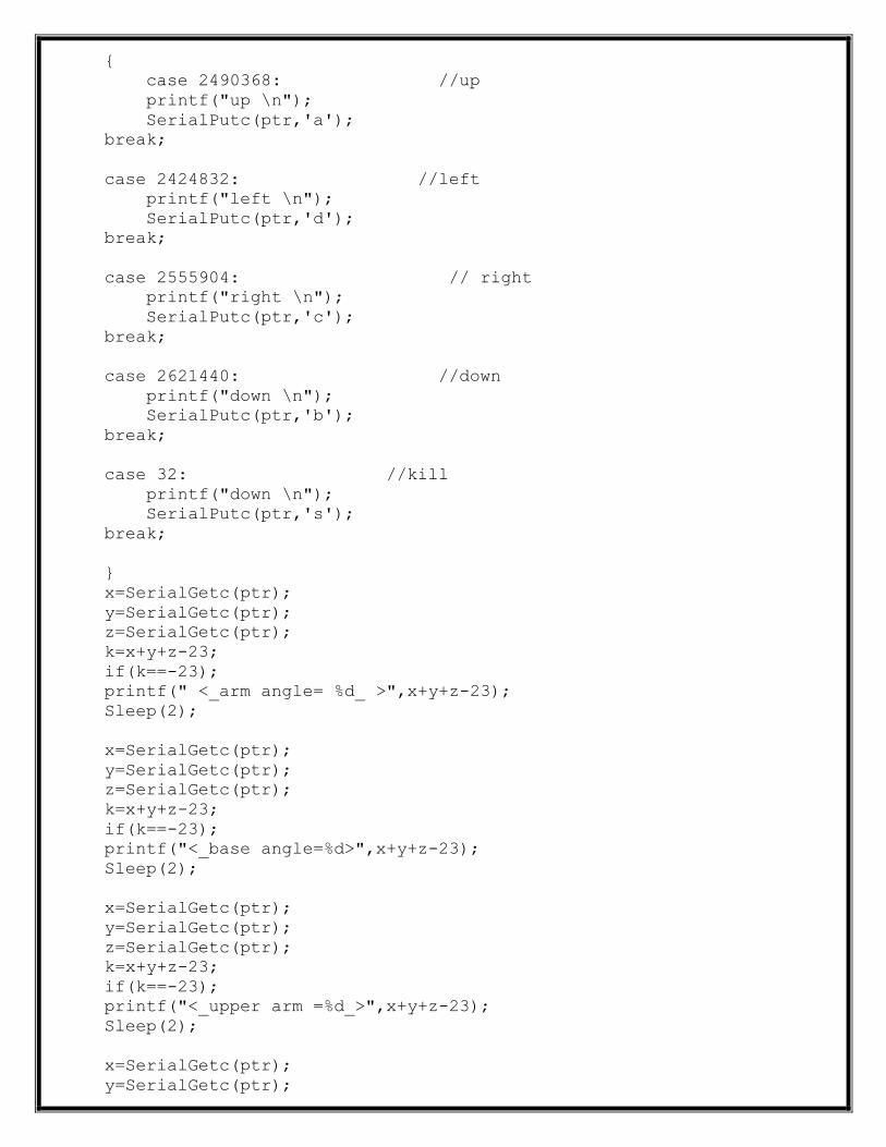
{
case 2490368: //up
printf("up \n");
SerialPutc(ptr,'a');
break;
case 2424832: //left
printf("left \n");
SerialPutc(ptr,'d');
break;
case 2555904: // right
printf("right \n");
SerialPutc(ptr,'c');
break;
case 2621440: //down
printf("down \n");
SerialPutc(ptr,'b');
break;
case 32: //kill
printf("down \n");
SerialPutc(ptr,'s');
break;
}
x=SerialGetc(ptr);
y=SerialGetc(ptr);
z=SerialGetc(ptr);
k=x+y+z-23;
if(k==-23);
printf(" <_arm angle= %d_ >",x+y+z-23);
Sleep(2);
x=SerialGetc(ptr);
y=SerialGetc(ptr);
z=SerialGetc(ptr);
k=x+y+z-23;
if(k==-23);
printf("<_base angle=%d>",x+y+z-23);
Sleep(2);
x=SerialGetc(ptr);
y=SerialGetc(ptr);
z=SerialGetc(ptr);
k=x+y+z-23;
if(k==-23);
printf("<_upper arm =%d_>",x+y+z-23);
Sleep(2);
x=SerialGetc(ptr);
y=SerialGetc(ptr);
z=SerialGetc(ptr);
k=x+y+z-23;
if(k!=-23);
printf("<_hand angle =%d_ >",x+y+z-23);
Sleep(2);
x=SerialGetc(ptr);
y=SerialGetc(ptr);
z=SerialGetc(ptr);
k=x+y+z-23;
if(k!=-23);
printf("<_finger1=%d_>",x+y+z-23);
Sleep(2);
x=SerialGetc(ptr);
y=SerialGetc(ptr);
z=SerialGetc(ptr);
k=x+y+z-23;
if(k!=-23);
printf("<accleratometer =%d_>",x+y+z-23);
Sleep(2);
x=SerialGetc(ptr);
y=SerialGetc(ptr);
z=SerialGetc(ptr);
k=x+y+z-23;
if(k!=-23);
printf("pressure sensor=%d_ >\n ",x+y+z-23);
Sleep(2);
cvGrabFrame( capture );
}
_tprintf (TEXT("Serial port %s successfully
reconfigured.\n"), pcCommPort);
cvDestroyAllWindows();
cvReleaseCapture( &capture );
}
12.2.3 The Arduino on the quadrotor controls the servo motor
using the following Code. The Signals to the servo motor is sent
with an attempt to minimise the turbulence. The signal is sent
to the BLDC ESC which in turn provides power to the servo motor.
#include <Servo.h>
Servo servof; //declaration of servo
Servo servob;
Servo servor;
Servo servol;
void setup() {
// initialize serial communication:
servof.attach(6); // pin declartion of servo
servob.attach(9);
servor.attach(10);
servol.attach(11);
Serial.begin(9600);
// initialize the LED pins:
}
void loop() {
// read the sensor:
int f=1000,b=1000,r=1000,l=1000, res=10,x=0, y=0,g=0;
char fc, bc, rc, lc, xc,yc,gc, input=100;
fc=f/10;
bc=b/10;
rc=r/10;
lc=l/10;
xc=x/5;
yc=y/5;
gc=g/10;
{
// input = Serial.read();
Serial.println(fc);
Serial.println(bc);
Serial.println(rc);
Serial.println(lc);
Serial.println(xc);
Serial.println(yc);
Serial.println(gc);
// do something different depending on the character
received.
// The switch statement expects single number values for
each case;
// in this exmaple, though, you're using single quotes to tell
// the controller to get the ASCII value for the character.
For
// example 'a' = 97, 'b' = 98, and so forth:
{
servof.writeMicroseconds(f); // initialise
servob.writeMicroseconds(b);
servor.writeMicroseconds(r);
servol.writeMicroseconds(l);
while(1)
{delay(200);
input = Serial.read();
x=analogRead(A0); delay(5);
y=analogRead(A1); delay(5);
g=analogRead(A2); delay(5);
Serial.println(fc=f/10); delay(5);
Serial.println(bc=b/10); delay(5);
Serial.println(rc=r/10); delay(5);
Serial.println(lc=l/10); delay(5);
Serial.println(xc=x/5); delay(5);
Serial.println(yc=y/5); delay(5);
Serial.println(gc=g/10); delay(5);
switch (input)
{
case 'a': //up
servof.writeMicroseconds(f=f+res);
servob.writeMicroseconds(b=b+res);
servor.writeMicroseconds(r=r+res);
servol.writeMicroseconds(l=l+res);
// Serial.println('a');
break;
case 'b':
if (f>0) // down
{
servof.writeMicroseconds(f=f-res);
if(b>0)
servob.writeMicroseconds(b=b-res);
if(r>0)
servor.writeMicroseconds(r=r-res);
if(l>0)
servol.writeMicroseconds(l=l-res);
// Serial.println('b');
}
break;
case 'c':
//forward
servof.writeMicroseconds(f=f+res);
servob.writeMicroseconds(b=b+res);
// Serial.println('c');
break;

case 'd': //backwrd
servor.writeMicroseconds(f=f+res);
if(b>0)
servol.writeMicroseconds(b=b+res);
// Serial.println('d');
break;
case 'e':
if(r>0)// right
servor.writeMicroseconds(r=r-res);
servol.writeMicroseconds(l=l+res);
// Serial.println('e');
break;
case 'f': // right
servor.writeMicroseconds(r=r+res);
if(l>0)
servol.writeMicroseconds(l=l-res);
// Serial.println('f');
break;
case 's': // left
servof.writeMicroseconds(f=1000);
servob.writeMicroseconds(b=1000);
servor.writeMicroseconds(r=1000);
servol.writeMicroseconds(l=1000);
// Serial.println('s');
break;
} }
} } }
PIN Configuration of a RS232: USB to Serial Converter
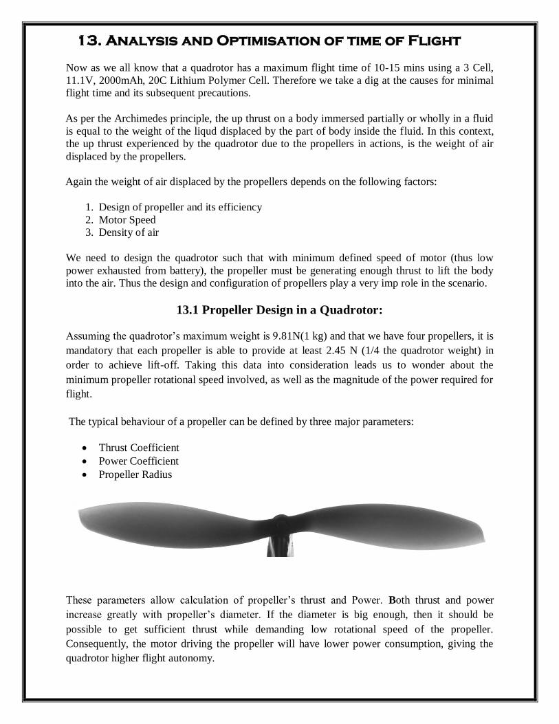
13. Analysis and Optimisation of time of Flight
Now as we all know that a quadrotor has a maximum flight time of 10-15 mins using a 3 Cell,
11.1V, 2000mAh, 20C Lithium Polymer Cell. Therefore we take a dig at the causes for minimal
flight time and its subsequent precautions.
As per the Archimedes principle, the up thrust on a body immersed partially or wholly in a fluid
is equal to the weight of the liqud displaced by the part of body inside the fluid. In this context,
the up thrust experienced by the quadrotor due to the propellers in actions, is the weight of air
displaced by the propellers.
Again the weight of air displaced by the propellers depends on the following factors:
1. Design of propeller and its efficiency
2. Motor Speed
3. Density of air
We need to design the quadrotor such that with minimum defined speed of motor (thus low
power exhausted from battery), the propeller must be generating enough thrust to lift the body
into the air. Thus the design and configuration of propellers play a very imp role in the scenario.
13.1 Propeller Design in a Quadrotor:
Assuming the quadrotor’s maximum weight is 9.81N(1 kg) and that we have four propellers, it is
mandatory that each propeller is able to provide at least 2.45 N (1/4 the quadrotor weight) in
order to achieve lift-off. Taking this data into consideration leads us to wonder about the
minimum propeller rotational speed involved, as well as the magnitude of the power required for
flight.
The typical behaviour of a propeller can be defined by three major parameters:
Thrust Coefficient
Power Coefficient
Propeller Radius
These parameters allow calculation of propeller’s thrust and Power. Both thrust and power
increase greatly with propeller’s diameter. If the diameter is big enough, then it should be
possible to get sufficient thrust while demanding low rotational speed of the propeller.
Consequently, the motor driving the propeller will have lower power consumption, giving the
quadrotor higher flight autonomy.
The propellers used in the rotors are fixed pitch, signifying that the pitch angle β, sometimes
referred to as the blade angle, remains fixed. However, this should not be confused with constant
pitch, as the pitch can vary along the length of the propeller blade but cannot be adjusted.
Propeller geometry can be complex, where the chord length c and airfoil profiles vary along the
length of the blade. The pitch angle determines the pitch of the propeller p, which is the distance
that the propeller moves through the air for each revolution, much like a screw. This is why
propellers are sometimes referred to as ‘air screws’. This relationship can be described as,
Where r is the distance along the blade where the specificpitch angle exists. Because of the
variation that exists, a ratio is commonly used known as the pitch diameter ratio,
Where D is the diameter of the propeller and x is therelative radios of the blade section and may
be represented as,
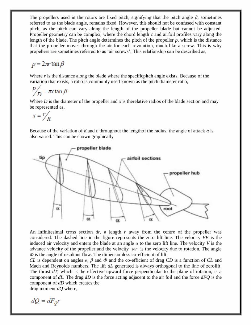
Because of the variation of β and c throughout the lengthof the radius, the angle of attack α is
also varied. This can be shown graphically
An infinitesimal cross section dr, a length r away from the centre of the propeller was
considered. The dashed line in the figure represents the zero lift line. The velocity VE is the
induced air velocity and enters the blade at an angle α to the zero lift line. The velocity V is the
advance velocity of the propeller and the velocity ωr is the velocity due to rotation. The angle
Ф is the angle of resultant flow. The dimensionless co-efficient of lift
CL is dependent on angles α, β and Ф and the co-efficient of drag CD is a function of CL and
Mach and Reynolds numbers. The lift dL generated is always orthogonal to the line of zerolift.
The thrust dT, which is the effective upward force perpendicular to the plane of rotation, is a
component of dL. The drag dD is the force acting adjacent to the air foil and the force dFQ is the
component of dD which creates the
drag moment dQ where,

The local lift and drag may be expressed as,
Where, ρ is the density of air. Vortex theory was analysed to determine the thrust and drag
moment. In the same manner in which a wing works, the aerodynamic lift on a propeller blade
can be related to a bound circulation Г around the blade,
This bound circulation may be expressed as,
Using the change in bound circulation, the local thrust and drag moments are,
Where, P and V are the global rotational and advance velocities respectively. From this, the local
efficiency of the propeller can be found,
To determine the overall efficiency of the propeller, a ratio of the product of the thrust and advance
velocity and the power P must be found.
However, the thrust and power may be represented as

It must be noted that D here refers to the rotor diameterand not drag. From this, the efficiency may be represented as
The velocity ratio in this expression is known as the advance ratio J,
And again to thrust, we have the following formulae:
FT(RPS)=CTρn2D4,
Where: FT = Thrust, ρ[slugsft3]=0.00238 - air density, n[RPS] - prop angular speed,
D[ft]=1012 - prop diameter. For calculating torque, the below formula must be used:
τ(RPS)=CPρn2D52π.
Now the following virtual simulation is done in order to improve flight time by making optimal
changes in propeller design.
Snapshot is attached below.
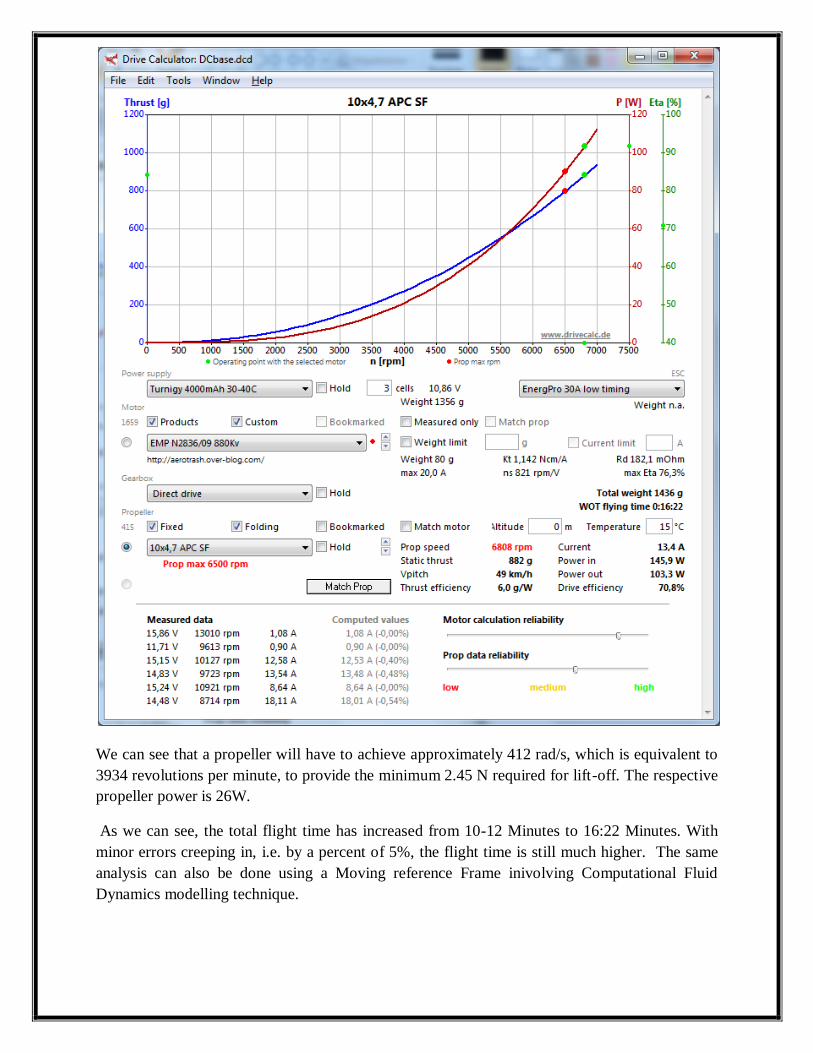
We can see that a propeller will have to achieve approximately 412 rad/s, which is equivalent to
3934 revolutions per minute, to provide the minimum 2.45 N required for lift-off. The respective
propeller power is 26W.
As we can see, the total flight time has increased from 10-12 Minutes to 16:22 Minutes. With
minor errors creeping in, i.e. by a percent of 5%, the flight time is still much higher. The same
analysis can also be done using a Moving reference Frame inivolving Computational Fluid
Dynamics modelling technique.

The quadrotor (symmetrical half model) geometry was created in Caedium Professional. The
CFD simulation was performed using the incompressible, steady-state RANS solver, with
multiple MRF, and the k-omega SST turbulence model
13.2 Optimal Environment Conditions for enhanced flight time:
Apart from that, the density of air also very important as more the density of air, more will be the
weight of air displaced and thus the power consumption will decrease. The density of air depends
on the following factors again:
1. Temperature of the air
2. Humidity
3. Altitude
4. Wind Flow
We have done a little research into the above mentioned factors to finally obtain the optimum
environment conditions and propeller design in order to enhance the flight time.
Density Of Air and other factors affecting it:
The density of air, is the mass per unit volume of Earth's atmosphere. Air density, like air
pressure, decreases with increasing altitude. It also changes with variation in temperature or
humidity.
We look into each of the factors one after another.
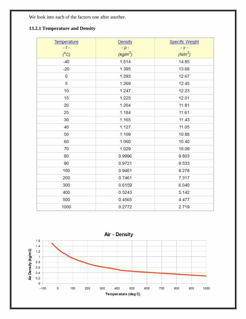
13.2.1 Temperature and Density

The density of dry air can be calculated using the ideal gas law, expressed as a function of
temperature and pressure:
where:
air density
absolute pressure
absolute temperature
specific gas constant for dry air
The specific gas constant for dry air is 287.058 J/(kg·K) in SI units. This quantity may vary
slightly depending on the molecular composition of air at a particular location.
At IUPAC standard temperature and pressure (0 °C and 100 kPa), dry air has a density of 1.2754
kg/m3. (At 20 °C and 101.325 kPa, dry air has a density of 1.2041 kg/m
3.)
13.2.2 Humidity (Water Vapor)
The addition of water vapor to air (making the air humid) reduces the density of the air, which
may at first appear counter-intuitive. This occurs because the molar mass of water (18 g/mol) is
less than the molar mass of dry air[note 1]
(around 29 g/mol). For any gas, at a given temperature
and pressure, the number of molecules present is constant for a particular volume (see
Avogadro's Law). So when water molecules (water vapor) are added to a given volume of air, the
dry air molecules must decrease by the same number, to keep the pressure or temperature from
increasing. Hence the mass per unit volume of the gas (its density) decreases.
The density of humid air may be calculated as a mixture of ideal gases. In this case, the partial
pressure of water vapor is known as the vapor pressure. Using this method, error in the density
calculation is less than 0.2% in the range of −10 °C to 50 °C. The density of humid air is found
by:
where:
Density of the humid air (kg/m³)
Partial pressure of dry air (Pa)
Specific gas constant for dry air, 287.058 J/(kg·K)
Temperature (K)
Pressure of water vapor (Pa)
Specific gas constant for water vapor, 461.495 J/(kg·K)
Molar mass of dry air, 0.028964 kg/mol
Molar mass of water vapor, 0.018016 kg/mol
Universal gas constant, 8.314 J/(K·mol)

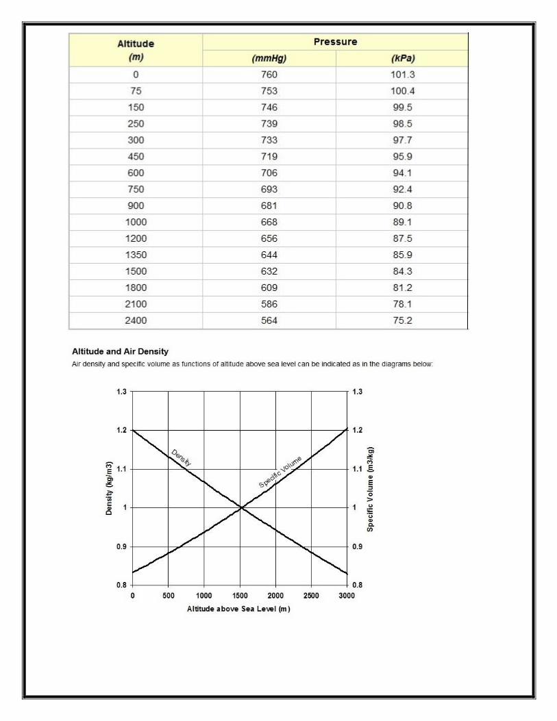
13.2.3 Altitude
Standard Atmosphere: p0=101.325 kPa, T0=288.15 K, =1.225 [[kg/m3]]
To calculate the density of air as a function of altitude, one requires additional parameters. They
are listed below, along with their values according to the International Standard Atmosphere,
using for calculation the universal gas constant instead of the air specific constant:
sea level standard atmospheric pressure, 101.325 kPa
sea level standard temperature, 288.15 K
earth-surface gravitational acceleration, 9.80665 m/s2
temperature lapse rate, 0.0065 K/m
ideal (universal) gas constant, 8.31447 J/(mol·K)
molar mass of dry air, 0.0289644 kg/mol
Temperature at altitude meters above sea level is approximated by the following formula (only
valid inside the troposphere):
The pressure at altitude is given by:
Density can then be calculated according to a molar form of the ideal gas law:
where:
molar mass
ideal gas constant
absolute temperature
absolute pressure must be in Pa and not the kPa above.
13.2.4 Wind Flow
Wind Flow is a very important aspect that must be taken into consideration before flying a
quadrotor. Even a minimal wind velocity can cause severe turbulence in the flight of the
Quadrotor. The Quadrotor is known for its non stability and yet is used as research purposes
taking into consideration its mechanical simplicity and other advantages. And in order to
balance the Quadrotor and get it stable even in the presence of medium/high wind velocity, 4
PID controllers have to be used for each of the following disturbances and their gain
simultaneously.
Pitch
Roll
Yaw
throttle
But that would have additional disadvantages in the system such as High power loss, Low flight
time, Low payload. Apart from that, the chances of crash increases rapidly in case of high wind
velocity.
13.3 ANALYSIS REPORT
For a Quadrotor with constant RPM of Servomotor, the height of Quadrotor differs
widely in different weather. With, Maximum height in winter due to high air density and
low temperature, and minimum height in summer, the difference in the height of the
Quadrotor is directly dependent on the temperature and specific weight of air.
It is advised not to fly the Quadrotor in Autumn season or any weather involving medium
or high wind velocity i.e V>25 Miles /Hr. The Quadrotor might crash or go out of control
due to excessive unwanted turbulence.
The design of propellers plays a most important part for deciding the time of flight. The
larger the diameter of propeller, the more is the upthrust and so less is the power
exhausted from battery for motor RPM.
In humid conditions or for the Quadrotor to fly above water bodies, the flight time
decreases by 30-40% keeping in account the low density of air.
The higher the Quadrotor flies, the less is the time of flight.
The propellers must be surrounded with a protective ring in order to avoid disturbances
caused due to change in direction of wind flow abruptly.
So in total, for maximum time of flight, the height of the flight of the Quadrotor should be kept
as low as possible with maximum diameter of propellers, keeping in mind the total size of the
vehicle. It should be avoided to fly the Quadrotor above water bodies and in humid or windy
weather. Since the range of XBEE Pro wireless module is within 1.6Km in line of sight RF
technique, the Quadrotor must be operated within the said range.

14. AREAS OF IMPLEMENTATION
14.1 Research platform:
Quadrotors are a useful tool for university researchers to test and evaluate new ideas in a number
of different fields, including flight control theory, navigation, real time systems and robotics. In
recent years many universities have shown “Quadrotors” performing increasingly complex
aerial manoeuvres. Swarms of “Quadrotors” can hover in mid-air, in formation, autonomously
perform complex flying routines such as flips, darting through hula-hoops and organise
themselves to fly through windows as a group. There are numerous advantages for using
“Quadrotor”s as versatile test platforms. They are relatively cheap, available in a variety of sizes
and their simple mechanical design means that they can be built and maintained by amateurs.
Due to the multi-disciplinary nature of operating a “Quadrotor”, academics from a number of
fields need to work together in order to make significant improvements to the way Quadrotor’s
perform. “Quadrotor” projects are typically collaborations between computer science, electronics
engineering and mechanical engineering specialists.
Because they are so manoeuvrable, “Quadrotors” could be useful in all kinds of situations
and environments. “Quadrotors” capable of autonomous flight could help remove the need for
people to put themselves in any number of dangerous positions. This is a prime reason that
research interest has been increasing over the years.
14.2 Military and law enforcement:
“Quadrotor” unmanned aerial vehicles are used for surveillance and reconnaissance by military
and law enforcement agencies, as well as search and rescue missions in urban environments.
One such example is the Aeryon Scout, created by Canadian company Aeryon Labs, which is a
small UAV that can quietly hover in place and use a camera to observe people and objects on the
ground.

(The RQ-7 Shadow is capable of delivering a 20 lb (9.1 kg) "Quick-MEDS" canister to front-line
troops.)
Beyond the military applications of UAVs with which "drones" became most associated,
numerous civil aviation uses have been developed, including aerial surveying of crops, acrobatic
aerial footage in filmmaking, search and rescue operations, inspecting power lines and pipelines,
and counting wildlife, with manufacturers rebranding the technology as "unmanned aerial
systems" (UASs) in preference over "drones."
14.3 Commercial:
The largest use of “Quadrotor” has been in the field of aerial imagery although, In the USA, it is
currently illegal to use remote controlled vehicles for commercial purposes. “Quadrotor” UAVs
are suitable for this job because of their autonomous nature and huge cost savings. Capturing
aerial imagery with a “Quadrotor” is as simple as programming GPS coordinates and hitting the
go button. Using on-board cameras, users have the option of being streamed live to the ground.
Many companies have used this for real estate photography to industrial systems inspection.
Various organizations are taking advantage of the Quadrotor’s closed-circuit television
capabilities and ability to provide an eye in the sky to the action below. Recently Amazon has
come up with an idea to drop parcels using multi Rotor aircraft thus decreasing manpower and
saving a lot of expenditure.
14.4 Remote sensing:
UAV remote sensing functions include electromagnetic spectrum sensors, gamma ray sensors,
biological sensors, and chemical sensors. A UAV's electromagnetic sensors typically include
visual spectrum, infrared, or near infrared cameras as well as radar systems. Other
electromagnetic wave detectors such as microwave and ultraviolet spectrum sensors may also be
used but are uncommon. Biological sensors are sensors capable of detecting the airborne
presence of various microorganisms and other biological factors. Chemical sensors use laser
spectroscopy to analyze the concentrations of each element in the air.
14.5 Commercial aerial surveillance:
Aerial surveillance of large areas is made possible with low cost UAV systems. Surveillance
applications include livestock monitoring, wildfire mapping, pipeline security, home security,
road patrol, and anti-piracy. The trend for the use of UAV technology in commercial aerial

surveillance is expanding rapidly with increased development of automated object detection
approaches.
14.6 Domestic policing:
UAVs are increasingly used for domestic police work in Canada and the United States: a dozen
US police forces had applied for UAV permits by March 2013. Texas politician and
commentator Jim Hightower has warned about potential privacy abuses from aerial surveillance.
In February 2013, Seattle Mayor Michael McGinn responded to protests by scrapping the Seattle
Police Department’s plan to deploy UAVs.
14.7 Oil, gas and mineral exploration and production:
UAVs can be used to perform geophysical surveys, in particular geomagnetic surveys where the
processed measurements of the Earth's differential magnetic field strength are used to calculate
the nature of the underlying magnetic rock structure. A knowledge of the underlying rock
structure helps trained geophysicists to predict the location of mineral deposits. The production
side of oil and gas exploration and production entails the monitoring of the integrity of oil and
gas pipelines and related installations. For above-ground pipelines, this monitoring activity could
be performed using digital cameras mounted on one or more UAVs. The InView Unmanned
Aircraft System is an example of a UAV developed for use in oil, gas, and mineral exploration
and production activities.
14.8 Transport:
UAVs can transport goods using various means based on the configuration of the UAV itself.
Most payloads are stored in an internal payload bay somewhere in the airframe. For many
helicopter configurations, external payloads can be tethered to the bottom of the airframe. With
fixed-wing UAVs, payloads can also be attached to the airframe, but aerodynamics of the aircraft
with the payload must be assessed. For such situations, payloads are often enclosed in
aerodynamic pods for transport.
14.9 Scientific Research:
Unmanned aircraft are especially useful in penetrating areas that may be too dangerous for
manned aircraft. The National Oceanic and Atmospheric Administration (NOAA) began
utilizing the Aerosonde unmanned aircraft system in 2006 as a hurricane hunter. AAI
Corporation subsidiary Aerosonde Pty Ltd. of Victoria, Australia, designs and manufactures the
35-pound system, which can fly into a hurricane and communicate near-real-time data directly to
the National Hurricane Center in Florida. Beyond the standard barometric pressure and
temperature data typically culled from manned hurricane hunters, the Aerosonde system provides
measurements far closer to the water’s surface than previously captured. Further applications for
unmanned aircraft can be explored once solutions have been developed for their accommodation
within national airspace, an issue currently under discussion by the Federal Aviation
Administration. UAVSI, the UK manufacturer, also produces a variant of their Vigilant light
UAS (20 kg) designed specifically for scientific research in severe climates, such as the
AntarctiC.
There have also been experiments with using UAVs as a construction and artwork tool at
locations such as the ETH Zurich.
14.10 Armed attacks:
MQ-1 Predator UAVs armed with Hellfire missiles are increasingly used by the U.S. as
platforms for hitting ground targets. The advantage of using an unmanned vehicle rather than a
manned aircraft in such cases is to avoid a diplomatic embarrassment should the aircraft be shot
down and the pilots captured, since the bombings take place in countries deemed friendly and
without the official permission of those countries. A Predator based in a neighboring Arab
country was used to kill suspected al-Qaeda terrorists in Yemen on November 3, 2002. This
marked the first use of an armed Predator as an attack aircraft outside of a theatre of war such as
Afghanistan.
In 2012, the USAF trained more UAV pilots than ordinary jet fighter pilots for the first
time.
One issue with using armed drones to attack human targets is the size of the bombs being used
and the relative lack of discrimination of the 100 lb (45 kg) Hellfire, which was designed to
eliminate tanks and attack bunkers. Smaller weapons such as the Raytheon Griffin and Small
Tactical Munition are being developed as a less indiscriminate alternative, and development is
underway on the still smaller US Navy-developed Spike missile. The payload-limited Predator A
can also be armed with six Griffin missiles, as opposed to only two of the much-heavier
Hellfires.

UAVs will likely play an increased role in search and rescue in the United States. This was
demonstrated by the use of UAVs during the 2008 hurricanes that struck Louisiana and Texas.
Micro UAVs, such as the Aeryon Scout, have been used to perform Search and Rescue activities
on a smaller scale, such as the search for missing persons. For example, Predators, operating
between 18,000–29,000 feet above sea level, performed search and rescue and damage
assessment. Payloads carried were an optical sensor, which is a daytime and infrared camera in
particular, and a synthetic aperture radar (SAR). The Predator's SAR is a sophisticated all-
weather sensor capable of providing photographic-like images through clouds, rain or fog, and in
daytime or nighttime conditions, all in real-time. A concept of coherent change detection in SAR
images allows for exceptional search and rescue ability: photos taken before and after the storm
hits are compared, and a computer highlights areas of damage.
14.11 Conservation:
In June 2012, WWF announced it will begin using UAVs in Nepal to aid conservation efforts
following a successful trial of two aircraft in Chitwan National Park, with ambitions to expand to
other countries, such as Tanzania and Malaysia. The global wildlife organization plans to train
ten personnel to use the UAVs, with operational use beginning in the fall. In August 2012, UAVs
were used by members of the Sea Shepherd Conservation Society in Namibia to document the
annual seal cull. In March 2013, the Times published a controversial story that UAV
conservation non-profit ShadowView, founded by former members of Sea Shepherd
Conservation Society, had been working for several months with anti-hunting charity The
League Against Cruel Sports to expose illegal fox hunting in the UK, hunt supporters have
argued that using UAVs to film hunting is an invasion of privacy.
14.12 Forest fire detection:
Another application of civil UAVs is the prevention and early detection of forest fires. The chief
exponent of this type is the FT-ALTEA, developed by Flightech Systems. The possibility of
constant flight, both day and night, makes the methods used until now (helicopters, watchtowers,
etc.) become obsolete. Its payload consists of numerous cameras (HD, thermal, hyperspectral,
etc.) and multiple sensors that provide real-time emergency services, including information about
the location of the outbreak of fire as well as many factors (wind speed, temperature, humidity,
etc.) that are helpful for fire crews to conduct fire suppression.
14.13 Archaeology:
In Peru archaeologists use drones to speed up survey work and protect sites from squatters,
builders and miners. Small drones helped researchers produce three-dimensional models of
Peruvian sites instead of the usual flat maps—and in days and weeks instead of months and
years.
Drones have replaced expensive and clumsy small planes, kites and helium balloons. Drones
costing as little as£650 have proven useful. In 2013 drones have flown over at least six Peruvian
archaeological sites, including the colonial Andean town Machu Llacta 4,000 metres (13,000 ft)
above sea level. The drones continue to have altitude problems in the Andes, leading to plans to
make a drone blimp, employing open source software.
Jeffrey Quilter, an archaeologist with Harvard University said, "You can go up three metres and
photograph a room, 300 metres and photograph a site, or you can go up 3,000 metres and
photograph the entire valley."
14.14 Future potential:
In the future, UAVs may be able to perform a variety of unique tasks apart from what they are
capable of today. Engineers are currently working to produce remotely piloted UAVs that are
capable of air to air combat, aerial refueling, combat search and rescue with facial recognition,
and resupply to agents on the ground.
Autonomy technology that is important to UAV development falls under the following
categories:
Sensor fusion: Combining information from different sensors for use on board the vehicle
Communications: Handling communication and coordination between multiple agents in
the presence of incomplete and imperfect information
Path planning: Determining an optimal path for vehicle to follow while meeting certain
objectives and mission constraints, such as obstacles or fuel requirements
Trajectory Generation (sometimes called Motion planning): Determining an optimal
control manoeuvre to take in order to follow a given path or to go from one location to
another
Trajectory Regulation: The specific control strategies required to constrain a vehicle
within some tolerance to a trajectory
Task Allocation and Scheduling: Determining the optimal distribution of tasks amongst a
group of agents within time and equipment constraints
Cooperative Tactics: Formulating an optimal sequence and spatial distribution of
activities between agents in order to maximize the chance of success in any given mission
scenario
To some extent, the ultimate goal in the development of autonomy technology is to replace
the human pilot. It remains to be seen whether future developments of autonomy technology, the
perception of the technology, and, most importantly, the political climate surrounding the use of
such technology will limit the development and utility of autonomy for UAV applications. Also
as a result of this, synthetic vision for piloting has not caught on in the UAV arena as it did with
manned aircraft. NASA utilized synthetic vision for test pilots on the HiMAT program in the
early 1980s, but the advent of more autonomous UAV autopilots greatly reduced the need for
this technology.
Solar-electric UAVs hold potential for unlimited flight, a concept originally championed
by the AstroFlight Sunrise in 1974 and the much later Aerovironment Helios Prototype,
which was destroyed in a 2003 crash.
14.15 Endurance:
Because UAVs are not burdened with the physiological limitations of human pilots, they can be
designed for maximized on-station times. The maximum flight duration of unmanned aerial
vehicles varies widely. Internal combustion engine aircraft endurance depends strongly on the
percentage of fuel burned as a fraction of total weight (the Breguet endurance equation) and so is
largely independent of aircraft size.
One of the uses for a high endurance UAV would be to "stare" at the battlefield for a long period
of time to produce a record of events that could then be played backwards to track where
improvised explosive devices (IEDs) came.
15. CONCLUSION
1. An unmanned vehicle like “Quadrotor” has many applications.
2. It can be used to decrease man hours and man power, as in it can be used by guards of our
own institute campus to survey the campus by the use of camera installed on it.
3. Various other telemetric sensors can also be installed on it like sensors to detect toxic gases
or various pressure and temperature sensors, and it can be used where the condition is
hazardous for men.
4. It can also be used for carrying pay loads from one place to another which can decrease use
of man power and in turn can result into economic profit.
5. The eye i.e. the camera installed on the “Quadrotor” can be used for ethical spying and
patrol.
6. There can be innumerable uses of a UAV like “Quadrotor” in coming future mostly in the
field of military. The Russian military force has a “Quadrotor” in which a machine gun is
installed and is so designed that it can handle recoil from gun firing also.

16. Reference
“Quadrotor Prototype” by Jorge Miguel Brito Domingues, Instituto Superior Tecnico,
Universidade Technica De Lisboa
Arduino.cc/en/Guide/
WWW.Engineeringtoolbox.com
http:// Wikipedia.en
https://fenix.tecnico.ulisboa.pt/downloadFile/2589867767331/Tese_de_Mestrado.pdf
http://phet.colorado.edu/en/simulation/buoyancy
http://www.symscape.com/computational-fluid-dynamics
http://droneflyers.com/2013/06/new-ebook-for-quadrotor-beginners/
http://physics.stackexchange.com/questions/31811/calculate-quadrotor-propeller-torque-
due-to-aerodynamic-drag
http://www.usconverters.com/usb-rs232-adapter-xs8801
http://www.irisa.fr/lagadic/pdf/2013_icra_ryll.pdf
http://www.academia.edu/705572/Aerodynamics_and_control_of_autonomous_quadroto
r_helicopters_in_aggressive_maneuvering by Steven Waslender
XBEE Manual
Arduino Manual and Software
Google Image Search
X-CTU Software
Code Blocks Software
RS 232 USB to Serial Converter and related drivers