department of mechanical engineering lab manual (2018-19)
TRANSCRIPT
QMP 7.1 D/F
Channabasaveshwara Institute of Technology (Affiliated to VTU, Belgaum & Approved by AICTE, New Delhi)
(NAAC Accredited & ISO 9001:2015 Certified Institution)
NH 206 (B.H. Road), Gubbi, Tumkur – 572 216. Karnataka.
Department of Mechanical Engineering
LAB MANUAL
(2018-19)
MATERIAL TESTING LABORATORY
(17MEL37A/47A)
III/IV Semester
Name:__________________________________________
U.S.N:__________________________________________
Batch:________________ Section:________________
QMP 7.1 D/F
Channabasaveshwara Institute of Technology (Affiliated to VTU, Belgaum & Approved by AICTE, New Delhi)
(NAAC Accredited & ISO 9001:2015 Certified Institution)
NH 206 (B.H. Road), Gubbi, Tumkur – 572 216. Karnataka.
Department of Mechanical Engineering
MATERIAL TESTING LABORATORY
2018-19
Prepared by: Approved by:
Dr. Sridhar S /Mr. Kiran Kumar M Y Mr. Giridhar S Kulkarni
Professor/Assistant Professor Associate Professor and Head,
Dept. of Mechanical Engineering Dept. of Mechanical Engineering
QMP 7.1 D/F
Channabasaveshwara Institute of Technology (Affiliated to VTU, Belgaum & Approved by AICTE, New Delhi)
(NAAC Accredited & ISO 9001:2015 Certified Institution)
NH 206 (B.H. Road), Gubbi, Tumkur – 572 216. Karnataka.
CONTENTS
SL.NO Subject Page No
01 Vision and Mission of college and department i
02 Syllabus ii
03 Objectives and Outcomes of the lab iv
04 Safety measures v
05 Material Testing Lab Layout vi
06 List of Experiments vii
07 Lab Lesson Plan viii
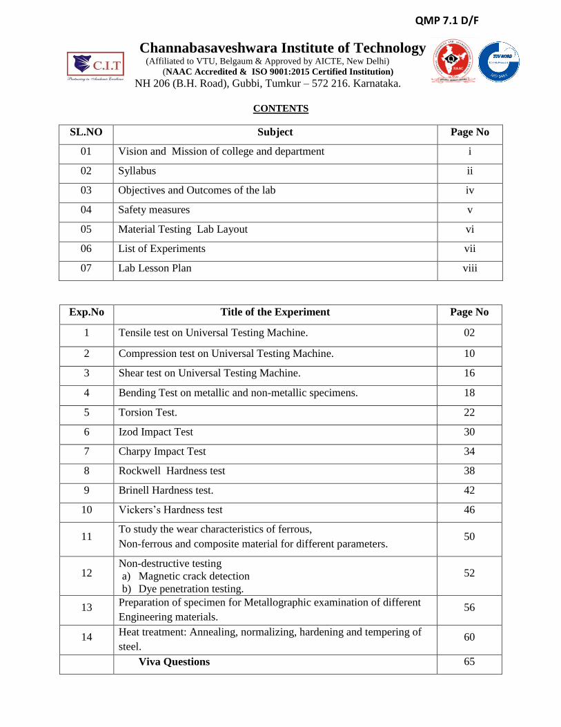
Exp.No Title of the Experiment Page No
1 Tensile test on Universal Testing Machine. 02
2 Compression test on Universal Testing Machine. 10
3 Shear test on Universal Testing Machine. 16
4 Bending Test on metallic and non-metallic specimens. 18
5 Torsion Test. 22
6 Izod Impact Test 30
7 Charpy Impact Test 34
8 Rockwell Hardness test 38
9 Brinell Hardness test. 42
10 Vickers’s Hardness test 46
11 To study the wear characteristics of ferrous,
Non-ferrous and composite material for different parameters. 50
12 Non-destructive testing
a) Magnetic crack detection
b) Dye penetration testing.
52
13 Preparation of specimen for Metallographic examination of different
Engineering materials. 56
14 Heat treatment: Annealing, normalizing, hardening and tempering of
steel. 60
Viva Questions 65

Channabasaveshwara Institute of Technology (Affiliated to VTU, Belgaum & Approved by AICTE, New Delhi)
(NAAC Accredited & ISO 9001:2015 Certified Institution)
NH 206 (B.H. Road), Gubbi, Tumkur – 572 216. Karnataka.
College Vision
To create centres of excellence in education and to serve the society by enhancing the quality
of life through value based professional leadership.
College Mission To provide high quality technical and professionally relevant education in a diverse learning
environment.
To provide the values that prepare students to lead their lives with personal integrity,
professional ethics and civic responsibility in a global society.
To prepare the next generation of skilled professionals to successfully compete in the
diverse global market.
To promote a campus environment that welcomes and honors women and men of all races,
creeds and cultures, values and intellectual curiosity, pursuit of knowledge and academic
integrity and freedom.
To offer a wide variety of off-campus education and training programmes to individuals
and groups.
To stimulate collaborative efforts with industry, universities, government and professional
societies.
To facilitate public understanding of technical issues and achieve excellence in the
operations of the institute.
Vision of the Department
To create state of the art learning environment to nurture the learning, blending human
values, academic professionalism and research process in the field of mechanical engineering
for the betterment of society.
Mission of the Department
The mission of the department is to provide requisite foundation to our students in
Mechanical Engineering provide cutting edge laboratory resources to bridge the gap between
theoretical and practical concepts provide exposure to various mechanical industries through
periodic industrial visits enhance our students skill set and to make them industry ready by
systematic skill development program.
i
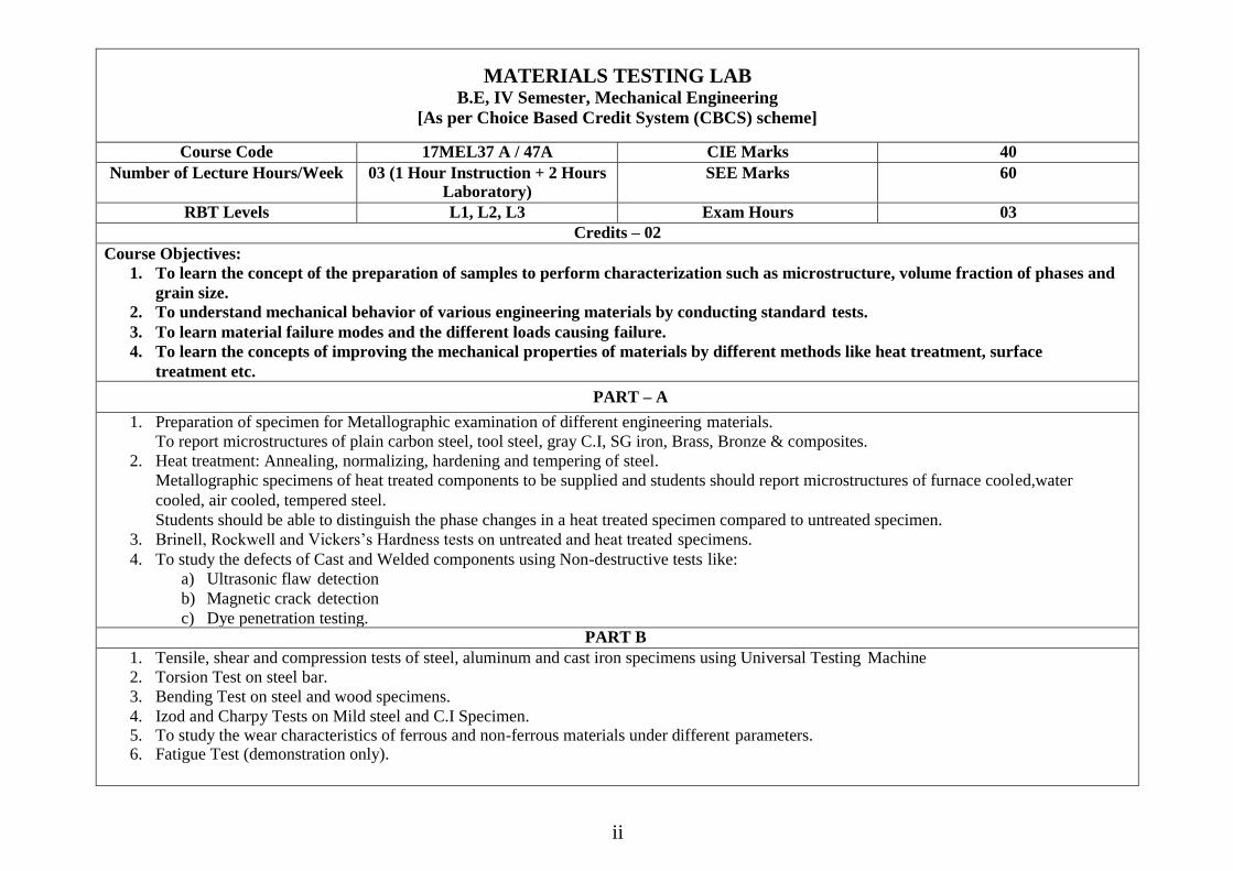
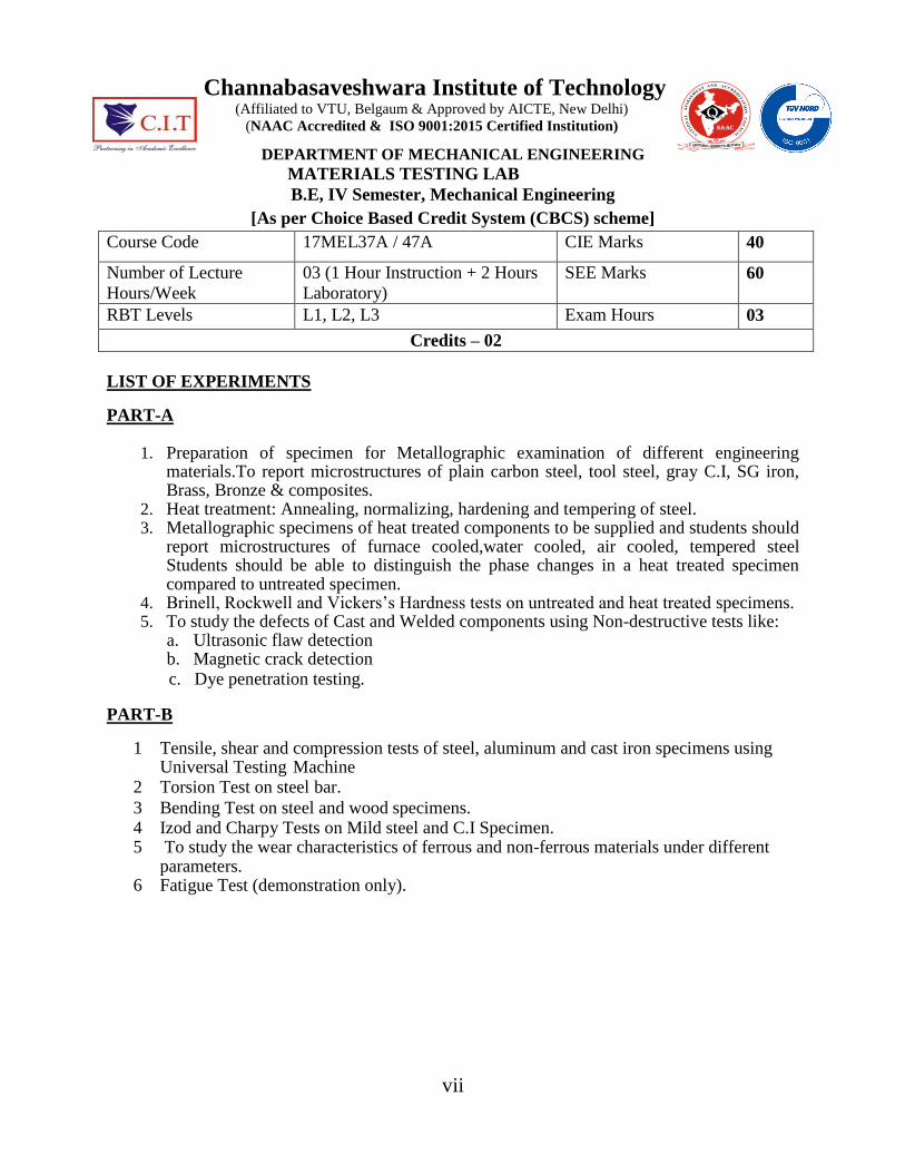
MATERIALS TESTING LAB B.E, IV Semester, Mechanical Engineering
[As per Choice Based Credit System (CBCS) scheme]
Course Code 17MEL37 A / 47A CIE Marks 40
Number of Lecture Hours/Week 03 (1 Hour Instruction + 2 Hours Laboratory)
SEE Marks 60
RBT Levels L1, L2, L3 Exam Hours 03
Credits – 02
Course Objectives:
1. To learn the concept of the preparation of samples to perform characterization such as microstructure, volume fraction of phases and
grain size.
2. To understand mechanical behavior of various engineering materials by conducting standard tests.
3. To learn material failure modes and the different loads causing failure.
4. To learn the concepts of improving the mechanical properties of materials by different methods like heat treatment, surface
treatment etc.
PART – A
1. Preparation of specimen for Metallographic examination of different engineering materials.
To report microstructures of plain carbon steel, tool steel, gray C.I, SG iron, Brass, Bronze & composites.
2. Heat treatment: Annealing, normalizing, hardening and tempering of steel.
Metallographic specimens of heat treated components to be supplied and students should report microstructures of furnace cooled,water
cooled, air cooled, tempered steel.
Students should be able to distinguish the phase changes in a heat treated specimen compared to untreated specimen.
3. Brinell, Rockwell and Vickers’s Hardness tests on untreated and heat treated specimens.
4. To study the defects of Cast and Welded components using Non-destructive tests like:
a) Ultrasonic flaw detection
b) Magnetic crack detection
c) Dye penetration testing. PART B
1. Tensile, shear and compression tests of steel, aluminum and cast iron specimens using Universal Testing Machine
2. Torsion Test on steel bar.
3. Bending Test on steel and wood specimens.
4. Izod and Charpy Tests on Mild steel and C.I Specimen. 5. To study the wear characteristics of ferrous and non-ferrous materials under different parameters. 6. Fatigue Test (demonstration only).
ii
iii
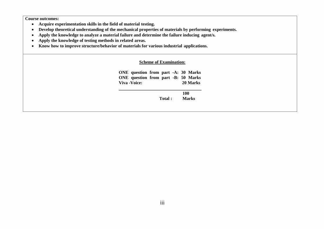
Course outcomes:
Acquire experimentation skills in the field of material testing.
Develop theoretical understanding of the mechanical properties of materials by performing experiments.
Apply the knowledge to analyze a material failure and determine the failure inducing agent/s.
Apply the knowledge of testing methods in related areas.
Know how to improve structure/behavior of materials for various industrial applications.
Scheme of Examination:
ONE question from part -A: 30 Marks
ONE question from part -B: 50 Marks
Viva -Voice: 20 Marks
100
Total : Marks
Channabasaveshwara Institute of Technology (Affiliated to VTU, Belgaum & Approved by AICTE, New Delhi)
(NAAC Accredited & ISO 9001:2015 Certified Institution)
NH 206 (B.H. Road), Gubbi, Tumkur – 572 216. Karnataka.
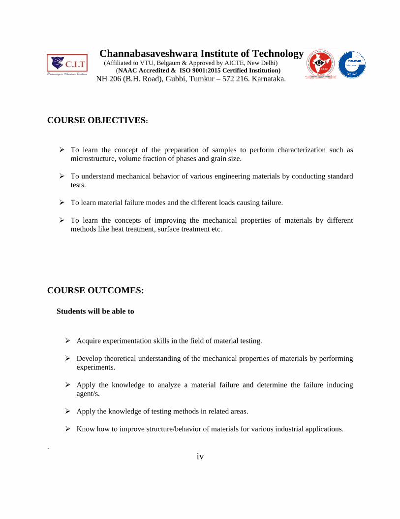
COURSE OBJECTIVES:
To learn the concept of the preparation of samples to perform characterization such as
microstructure, volume fraction of phases and grain size.
To understand mechanical behavior of various engineering materials by conducting standard
tests.
To learn material failure modes and the different loads causing failure.
To learn the concepts of improving the mechanical properties of materials by different
methods like heat treatment, surface treatment etc.
COURSE OUTCOMES:
Students will be able to
Acquire experimentation skills in the field of material testing.
Develop theoretical understanding of the mechanical properties of materials by performing
experiments.
Apply the knowledge to analyze a material failure and determine the failure inducing
agent/s.
Apply the knowledge of testing methods in related areas.
Know how to improve structure/behavior of materials for various industrial applications.
.
iv
Channabasaveshwara Institute of Technology (Affiliated to VTU, Belgaum & Approved by AICTE, New Delhi)
(NAAC Accredited & ISO 9001:2015 Certified Institution)
NH 206 (B.H. Road), Gubbi, Tumkur – 572 216. Karnataka.
Department of Mechanical Engineering
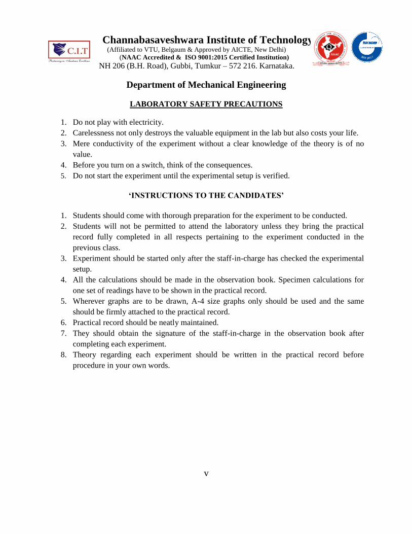
LABORATORY SAFETY PRECAUTIONS
1. Do not play with electricity.
2. Carelessness not only destroys the valuable equipment in the lab but also costs your life.
3. Mere conductivity of the experiment without a clear knowledge of the theory is of no
value.
4. Before you turn on a switch, think of the consequences.
5. Do not start the experiment until the experimental setup is verified.
‘INSTRUCTIONS TO THE CANDIDATES’
1. Students should come with thorough preparation for the experiment to be conducted.
2. Students will not be permitted to attend the laboratory unless they bring the practical
record fully completed in all respects pertaining to the experiment conducted in the
previous class.
3. Experiment should be started only after the staff-in-charge has checked the experimental
setup.
4. All the calculations should be made in the observation book. Specimen calculations for
one set of readings have to be shown in the practical record.
5. Wherever graphs are to be drawn, A-4 size graphs only should be used and the same
should be firmly attached to the practical record.
6. Practical record should be neatly maintained.
7. They should obtain the signature of the staff-in-charge in the observation book after
completing each experiment.
8. Theory regarding each experiment should be written in the practical record before
procedure in your own words.
v
Channabasaveshwara Institute of Technology (Affiliated to VTU, Belgaum & Approved by AICTE, New Delhi)
(NAAC Accredited & ISO 9001:2015 Certified Institution)
DEPARTMENT OF MECHANICAL ENGINEERING
MATERIALS TESTING LAB
B.E, IV Semester, Mechanical Engineering
[As per Choice Based Credit System (CBCS) scheme]
Course Code 17MEL37A / 47A CIE Marks 40
Number of Lecture
Hours/Week
03 (1 Hour Instruction + 2 Hours
Laboratory)
SEE Marks 60
RBT Levels L1, L2, L3 Exam Hours 03
Credits – 02
LIST OF EXPERIMENTS
PART-A 1. Preparation of specimen for Metallographic examination of different engineering
materials.To report microstructures of plain carbon steel, tool steel, gray C.I, SG iron, Brass, Bronze & composites.
2. Heat treatment: Annealing, normalizing, hardening and tempering of steel. 3. Metallographic specimens of heat treated components to be supplied and students should
report microstructures of furnace cooled,water cooled, air cooled, tempered steel Students should be able to distinguish the phase changes in a heat treated specimen compared to untreated specimen.
4. Brinell, Rockwell and Vickers’s Hardness tests on untreated and heat treated specimens. 5. To study the defects of Cast and Welded components using Non-destructive tests like:
a. Ultrasonic flaw detection b. Magnetic crack detection
c. Dye penetration testing.
PART-B
1 Tensile, shear and compression tests of steel, aluminum and cast iron specimens using Universal Testing Machine
2 Torsion Test on steel bar.
3 Bending Test on steel and wood specimens. 4 Izod and Charpy Tests on Mild steel and C.I Specimen. 5 To study the wear characteristics of ferrous and non-ferrous materials under different
parameters. 6 Fatigue Test (demonstration only).
vii
Channabasaveshwara Institute of Technology (Affiliated to VTU, Belgaum & Approved by AICTE, New Delhi)
(NAAC Accredited & ISO 9001:2015 Certified Institution)
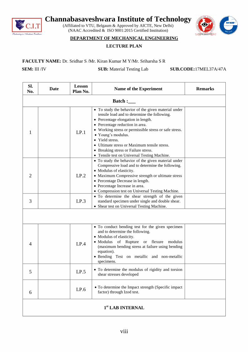
DEPARTMENT OF MECHANICAL ENGINEERING
LECTURE PLAN
FACULTY NAME: Dr. Sridhar S /Mr. Kiran Kumar M Y/Mr. Sriharsha S R
SEM: III /IV SUB: Material Testing Lab SUB.CODE:17MEL37A/47A
Sl. No.
Date Lesson
Plan No. Name of the Experiment Remarks
Batch :___
1 LP.1
To study the behavior of the given material under
tensile load and to determine the following.
Percentage elongation in length.
Percentage reduction in area.
Working stress or permissible stress or safe stress.
Young’s modulus.
Yield stress.
Ultimate stress or Maximum tensile stress.
Breaking stress or Failure stress.
Tensile test on Universal Testing Machine.
2 LP.2
To study the behavior of the given material under
Compressive load and to determine the following.
Modulus of elasticity.
Maximum Compressive strength or ultimate stress
Percentage Decrease in length.
Percentage Increase in area.
Compression test on Universal Testing Machine.
3 LP.3 To determine the shear strength of the given
standard specimen under single and double shear.
Shear test on Universal Testing Machine.
4 LP.4
To conduct bending test for the given specimen
and to determine the following.
Modulus of elasticity.
Modulus of Rupture or flexure modulus
(maximum bending stress at failure using bending
equation).
Bending Test on metallic and non-metallic
specimens.
5 LP.5 To determine the modulus of rigidity and torsion
shear stresses developed
6 LP.6
To determine the Impact strength (Specific impact
factor) through Izod test.
1
st LAB INTERNAL
viii
7 LP.7 To determine the Impact strength (Specific impact
factor) through Charpy test
8 LP.8 To determine the Rockwell hardness number of
the given Specimen using “Rockwell Hardness
tester”.
9.
LP.9
To determine the Brinell hardness number of the
given Specimen using Brinell hardness tester.
10. LP.10 To determine the hardness of the given Specimen
using Vicker’s hardness test
11. LP.11 To determine wear and co-efficient of friction of a
standard specimen using pin-on-disk wear testing
machine
12. LP.12
Introduction to MMT Lab & Non-destructive test
experiments like ultrasonic flaw detection,
magnetic crack detection and die penetration
testing.[ To study the defects of cast weld od
welded specimen ]
2
nd LAB INTERNAL
13. LP.13
Introduction: Preparation of specimen for
Metallography examination of different
engineering materials. Identification of
microstructures of Plane carbon steel, brass,
bronze and composites Wear test
14. LP.14 Heat Treatment: Annealing, Normalizing,
Hardening and Tempering of Steel. Hardness
study of heat treated samples.
3
rd LAB INTERNAL
EXTRA LABS
Month DATE
February
March
April
May
Signature of staff H.O.D
ix
Material Testing Lab 17MEL37A/47A III/IV
Dept. of ME, CIT, Gubbi- 572216 Page 1
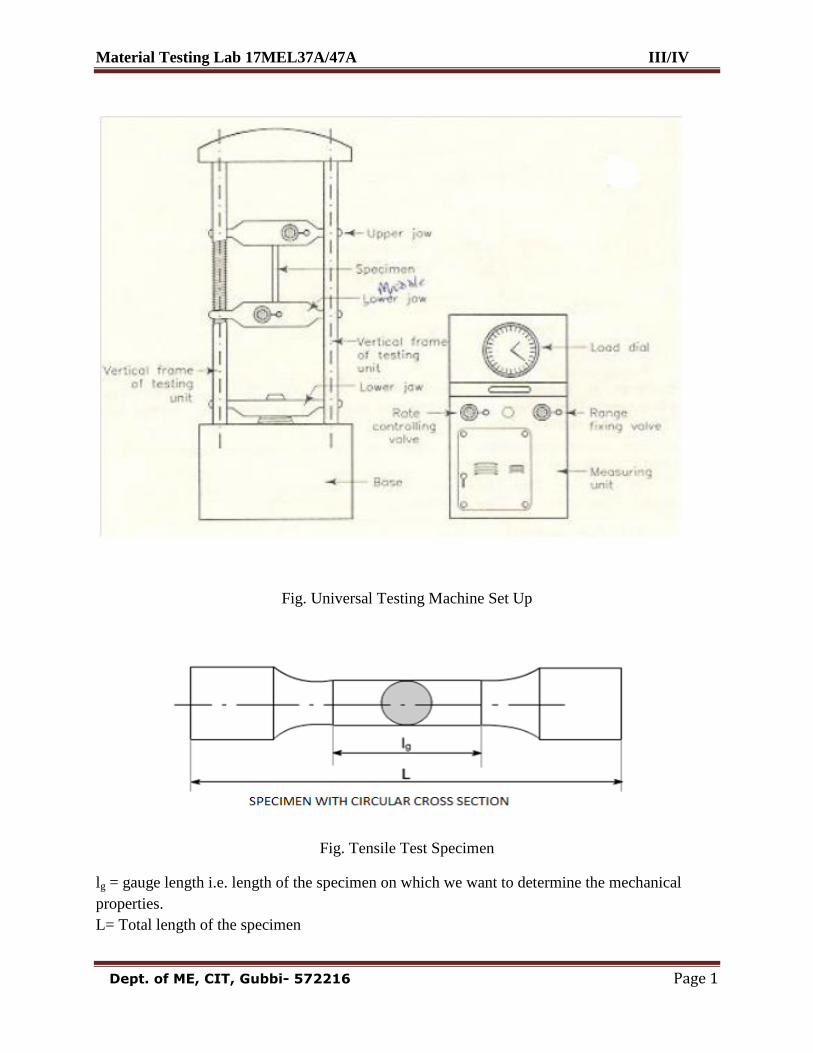
Fig. Universal Testing Machine Set Up
Fig. Tensile Test Specimen
lg = gauge length i.e. length of the specimen on which we want to determine the mechanical
properties.
L= Total length of the specimen
Material Testing Lab 17MEL37A/47A III/IV
Dept. of ME, CIT, Gubbi- 572216 Page 2
Experiment 1: Date: __ /__ / _____
TENSION TEST
AIM: To study the behavior of the given material under tensile load and to determine the
followings:
Percentage elongation in length
Percentage reduction in area
Working stress or permissible stress or safe stress
Young‟s modulus
Yield stress
Ultimate stress or Maximum tensile stress
Breaking stress or Failure stress
Practical importance: while designing a component, selection of metals for different
applications is based on salient points such as limit of proportionality or elastic limit, yield
strength, ultimate strength, and breaking strength. Therefore, from this tension test above said
salient points can be calculated.
Apparatus Required:
Universal Testing machine, Dial gauge, Vernier caliper and scale.
Theory:
In engineering, tension test is widely used to provide basic design information on the
strength of the materials. In the tension test a specimen is subjected to a continually increasing
uniaxial tensile force while simultaneous observations are made of the elongation of the
specimen. A stress-strain curve is plotted from the load-elongation measurements.
The parameters which are used to describe the stress-strain curve of a material are the
tensile strength, yield strength or yield point, percent elongation and reduction of area. The first
two are strength parameters; the last two indicate ductility.
Definitions:
Limit of proportionality (A): It is the limiting value of the stress up to which stress is
proportional to strain.
Elastic limit: This is the limiting value of stress up to which if the material is stressed and then
released (unloaded), Strain disappears completely and the original length is regained.
Upper Yield Point (B): This is the stress at which, the load starts reducing and the extension
increases. This phenomenon is called yielding of material.
Material Testing Lab 17MEL37A/47A III/IV
Dept. of ME, CIT, Gubbi- 572216 Page 3
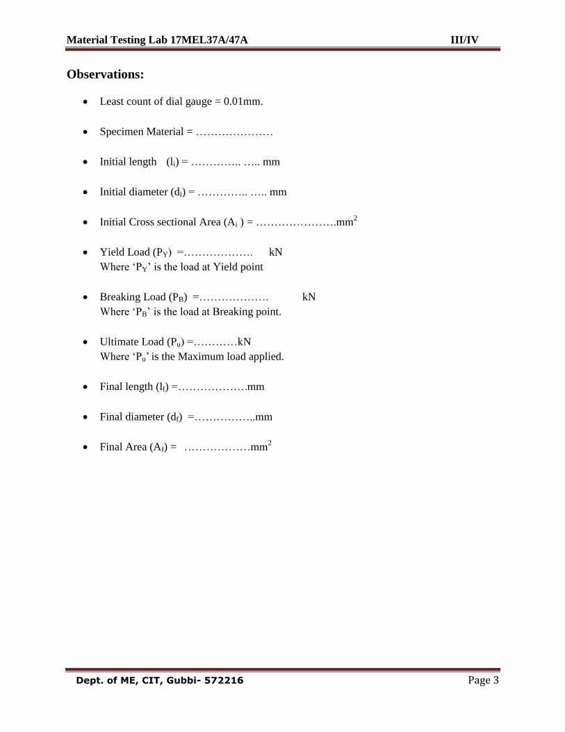
Observations:
Least count of dial gauge = 0.01mm.
Specimen Material = …………………
Initial length (li) = ………….. ….. mm
Initial diameter (di) = ………….. ….. mm
Initial Cross sectional Area (Ai ) = ………………….mm2
Yield Load (PY) =………………. kN
Where „PY‟ is the load at Yield point
Breaking Load (PB) =………………. kN
Where „PB‟ is the load at Breaking point.
Ultimate Load (Pu) =…………kN
Where „Pu‟ is the Maximum load applied.
Final length (lf) =……………….mm
Final diameter (df) =……………..mm
Final Area (Af) = ………………mm
2
Material Testing Lab 17MEL37A/47A III/IV
Dept. of ME, CIT, Gubbi- 572216 Page 4
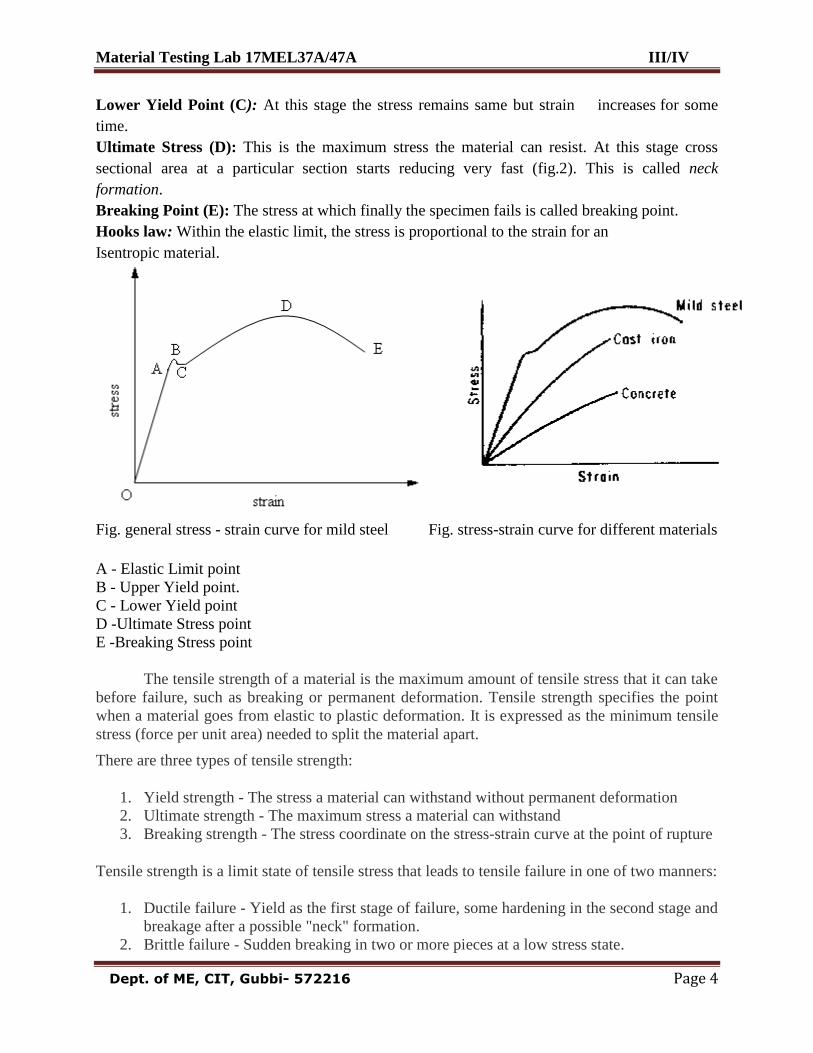
Lower Yield Point (C): At this stage the stress remains same but strain increases for some
time.
Ultimate Stress (D): This is the maximum stress the material can resist. At this stage cross
sectional area at a particular section starts reducing very fast (fig.2). This is called neck
formation.
Breaking Point (E): The stress at which finally the specimen fails is called breaking point.
Hooks law: Within the elastic limit, the stress is proportional to the strain for an
Isentropic material.
Fig. general stress - strain curve for mild steel Fig. stress-strain curve for different materials
A - Elastic Limit point
B - Upper Yield point.
C - Lower Yield point
D -Ultimate Stress point
E -Breaking Stress point
The tensile strength of a material is the maximum amount of tensile stress that it can take
before failure, such as breaking or permanent deformation. Tensile strength specifies the point
when a material goes from elastic to plastic deformation. It is expressed as the minimum tensile
stress (force per unit area) needed to split the material apart.
There are three types of tensile strength:
1. Yield strength - The stress a material can withstand without permanent deformation
2. Ultimate strength - The maximum stress a material can withstand
3. Breaking strength - The stress coordinate on the stress-strain curve at the point of rupture
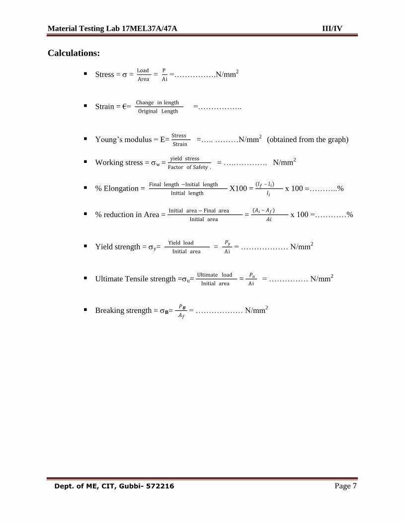
Tensile strength is a limit state of tensile stress that leads to tensile failure in one of two manners:
1. Ductile failure - Yield as the first stage of failure, some hardening in the second stage and
breakage after a possible "neck" formation.
2. Brittle failure - Sudden breaking in two or more pieces at a low stress state.
Material Testing Lab 17MEL37A/47A III/IV
Dept. of ME, CIT, Gubbi- 572216 Page 5
Tabular Column:
Sl.
No.
Load
(kN) Load (N)
Extension (δl )
In mm
Stress in
N/mm2
Strain
Young’s
modulus
(N/mm2)
1
E = Stress
Strain
Result
from
the graph
2
3
4
5
6
7
8
9
10
11
12
13
14
15
Material Testing Lab 17MEL37A/47A III/IV
Dept. of ME, CIT, Gubbi- 572216 Page 6
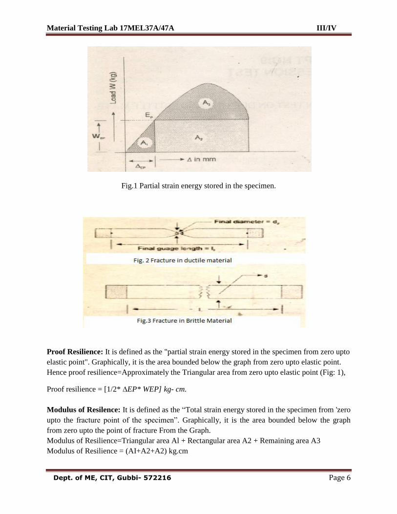
Fig.1 Partial strain energy stored in the specimen.
Proof Resilience: It is defined as the "partial strain energy stored in the specimen from zero upto
elastic point". Graphically, it is the area bounded below the graph from zero upto elastic point.
Hence proof resilience=Approximately the Triangular area from zero upto elastic point (Fig: 1),
Proof resilience = [1/2* ∆EP* WEP] kg- cm.
Modulus of Resilence: It is defined as the “Total strain energy stored in the specimen from 'zero
upto the fracture point of the specimen”. Graphically, it is the area bounded below the graph
from zero upto the point of fracture From the Graph.
Modulus of Resilience=Triangular area Al + Rectangular area A2 + Remaining area A3
Modulus of Resilience = (AI+A2+A2) kg.cm
Material Testing Lab 17MEL37A/47A III/IV
Dept. of ME, CIT, Gubbi- 572216 Page 7
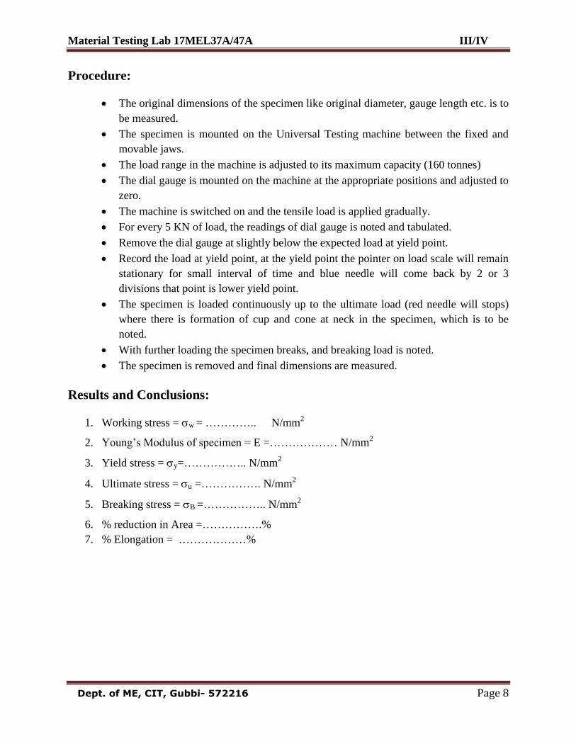
Calculations:
Stress = = Load
Area =
P
Ai =…………….N/mm
2
Strain = €= Change in length
Original Length =……………..
Young‟s modulus = E= Stress
Strain =….. ………N/mm
2 (obtained from the graph)
Working stress = w = yield stress
Factor of Safety . = ….…………. N/mm
2
% Elongation = Final length −Initial length
Initial length X100 =
(𝑙𝑓 – 𝑙𝑖)
𝑙𝑖 x 100 ………..%
% reduction in Area = Initial area − Final area
Initial area =
(𝐴𝑖 – 𝐴𝑓)
𝐴𝑖 x 100 =…………%
Yield strength = y= Yield load
Initial area =
𝑃𝑦
Ai = ……………… N/mm
2
Ultimate Tensile strength =u= Ultimate load
Initial area =
𝑃𝑢
Ai = …………… N/mm
2
Breaking strength = B= 𝑃𝑩
𝐴𝑓 = ……………… N/mm
2
Material Testing Lab 17MEL37A/47A III/IV
Dept. of ME, CIT, Gubbi- 572216 Page 8
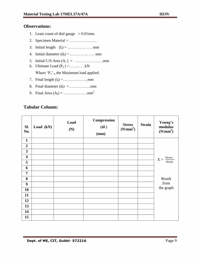
Procedure:
The original dimensions of the specimen like original diameter, gauge length etc. is to
be measured.
The specimen is mounted on the Universal Testing machine between the fixed and
movable jaws.
The load range in the machine is adjusted to its maximum capacity (160 tonnes)
The dial gauge is mounted on the machine at the appropriate positions and adjusted to
zero.
The machine is switched on and the tensile load is applied gradually.
For every 5 KN of load, the readings of dial gauge is noted and tabulated.
Remove the dial gauge at slightly below the expected load at yield point.
Record the load at yield point, at the yield point the pointer on load scale will remain
stationary for small interval of time and blue needle will come back by 2 or 3
divisions that point is lower yield point.
The specimen is loaded continuously up to the ultimate load (red needle will stops)
where there is formation of cup and cone at neck in the specimen, which is to be
noted.
With further loading the specimen breaks, and breaking load is noted.
The specimen is removed and final dimensions are measured.
Results and Conclusions:
1. Working stress = w = ………….. N/mm2
2. Young‟s Modulus of specimen = E =……………… N/mm2
3. Yield stress = y=…………….. N/mm2
4. Ultimate stress = u =……………. N/mm2
5. Breaking stress = B =…………….. N/mm2
6. % reduction in Area =…………….%
7. % Elongation = ………………%
Material Testing Lab 17MEL37A/47A III/IV
Dept. of ME, CIT, Gubbi- 572216 Page 9
Observations:
1. Least count of dial gauge = 0.01mm.
2. Specimen Material = …………………
3. Initial length (li) = ………….. ….. mm
4. Initial diameter (di) = ………….. ….. mm
5. Initial C/S Area (Ai ) = ………………….mm
6. Ultimate Load (Pu ) =…………kN
Where „Pu‟ is the Maximum load applied.
7. Final length (lf) =……………….mm
8. Final diameter (df) =……………..mm
9. Final Area (Af) = ………………mm2
Tabular Column:
Sl.
No.
Load (kN)
Load
(N)
Compression
(δl )
(mm)
Stress
(N/mm2)
Strain
Young’s
modulus
(N/mm2)
1
E = Stress
Strain
Result
from
the graph
2
3
4
5
6
7
8
9
10
11
12
13
14
15
Material Testing Lab 17MEL37A/47A III/IV
Dept. of ME, CIT, Gubbi- 572216 Page 10
Experiment 2: Date: __ /__ / _____
COMPRESSION TEST
AIM: To study the behavior of the given material under Compressive load and to determine the
following:
Modulus of elasticity
Maximum Compressive strength or ultimate stress
Percentage Decrease in length
Percentage Increase in area
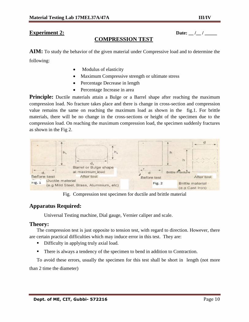
Principle: Ductile materials attain a Bulge or a Barrel shape after reaching the maximum
compression load. No fracture takes place and there is change in cross-section and compression
value remains the same on reaching the maximum load as shown in the fig.1. For brittle
materials, there will be no change in the cross-sections or height of the specimen due to the
compression load. On reaching the maximum compression load, the specimen suddenly fractures
as shown in the Fig 2.
Fig. Compression test specimen for ductile and brittle material
Apparatus Required:
Universal Testing machine, Dial gauge, Vernier caliper and scale.
Theory: The compression test is just opposite to tension test, with regard to direction. However, there
are certain practical difficulties which may induce error in this test. They are:
Difficulty in applying truly axial load.
There is always a tendency of the specimen to bend in addition to Contraction.
To avoid these errors, usually the specimen for this test shall be short in length (not more
than 2 time the diameter)
Material Testing Lab 17MEL37A/47A III/IV
Dept. of ME, CIT, Gubbi- 572216 Page 11
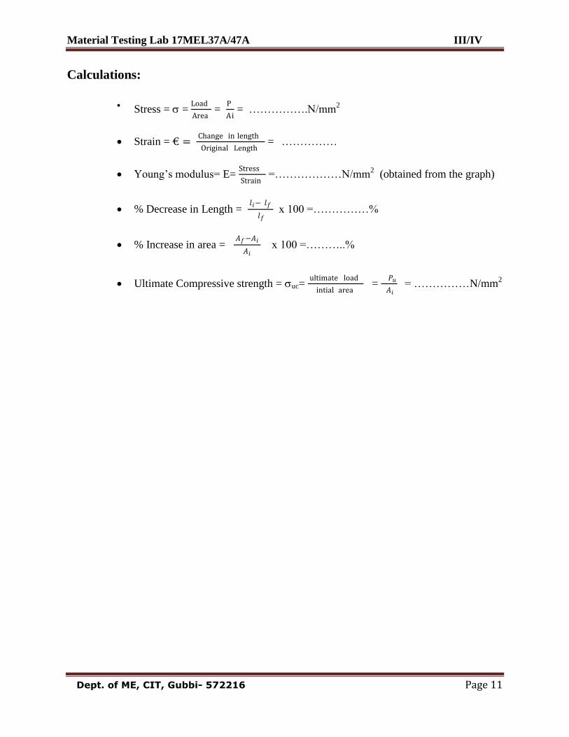
Calculations:
Stress = =
Load
Area =
P
Ai = …………….N/mm
2
Strain = € = Change in length
Original Length = ……………
Young‟s modulus= E= Stress
Strain =………………N/mm
2 (obtained from the graph)
% Decrease in Length = 𝑙𝑖− 𝑙𝑓
𝑙𝑓 x 100 =……………%
% Increase in area = 𝐴𝑓−𝐴𝑖
𝐴𝑖 x 100 =………..%
Ultimate Compressive strength = uc= ultimate load
intial area =
𝑃𝑢
𝐴𝑖 = ……………N/mm
2
Material Testing Lab 17MEL37A/47A III/IV
Dept. of ME, CIT, Gubbi- 572216 Page 12
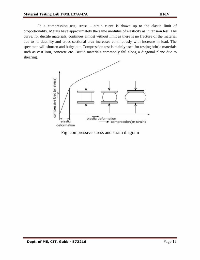
In a compression test, stress – strain curve is drawn up to the elastic limit of
proportionality. Metals have approximately the same modulus of elasticity as in tension test. The
curve, for ductile materials, continues almost without limit as there is no fracture of the material
due to its ductility and cross sectional area increases continuously with increase in load. The
specimen will shorten and bulge out. Compression test is mainly used for testing brittle materials
such as cast iron, concrete etc. Brittle materials commonly fail along a diagonal plane due to
shearing.
Fig. compressive stress and strain diagram

Material Testing Lab 17MEL37A/47A III/IV
Dept. of ME, CIT, Gubbi- 572216 Page 13
Material Testing Lab 17MEL37A/47A III/IV
Dept. of ME, CIT, Gubbi- 572216 Page 14
Procedure:
The original dimensions of the specimen like original dia., gauge length etc. is to be
measured.
The specimen is mounted on the Universal Testing machine between the fixed and
movable jaws.
The load range in the machine is adjusted to its maximum capacity (300 kN)
The dial gauge is mounted on the machine at the appropriate positions and adjusted to
zero.
The machine is switched on and the compressive load is applied gradually.
For every 10 kN of load, the readings of dial gauge is noted and tabulated.
Remove the dial gauge at slightly below the expected load at yield point.
Record the load at yield point, at the yield point the pointer on load scale will remain
stationary for small interval of time and blue needle will come back by 1 or 2
divisions that point is lower yield point.
The specimen is loaded continuously up to the ultimate load (red needle will stops)
which is to be noted.
The specimen is removed and final dimensions are measured.
Results and Conclusions:
1. Modulus of elasticity = E =……………N/mm2
2. Maximum Compressive strength or ultimate stress = uc=…………….N/mm2
3. Percentage Decrease in length =………..%
4. Percentage Increase in area =……………….%
Material Testing Lab 17MEL37A/47A III/IV
Dept. of ME, CIT, Gubbi- 572216 Page 15
Observations
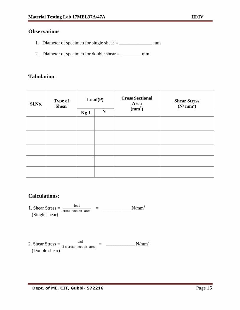
1. Diameter of specimen for single shear = ______________ mm
2. Diameter of specimen for double shear = _________mm
Tabulation:
Sl.No. Type of
Shear
Load(P) Cross Sectional
Area
(mm2)
Shear Stress
(N/ mm2)
Kg-f N
Calculations:
1. Shear Stress = load
cross section area = ________ ____N/mm
2
(Single shear)
2. Shear Stress = load
2 x cross section area = ____________ N/mm
2
(Double shear)
Material Testing Lab 17MEL37A/47A III/IV
Dept. of ME, CIT, Gubbi- 572216 Page 16
Experiment 3: Date: __ /__ / _____
SHEAR TEST
AIM: To determine the shear strength of the given standard specimen under
single and double shear.
Apparatus: UTM, Vernier Calipers, Standard MS Specimen
Theory:
A shear stress acts parallel to a C/S plane where as tensile and compressive stresses act at
normal to the C/S plane. For direct shear test of metals, a bar is usually sheared in the same
device that changes the position of the specimen while the remaining position is subject to load
by suitable dies.
Procedure:
1. Measure the diameter of the specimen
2. Fix the shear Specimen in the Single/Double Shear fixture.
3. Keep the shear equipment on the fixed jaw of UTM and apply the load slowly at right angles
to the axis of piece through the central block.
4. Note the load at fracture.
Results and Conclusions:
1. Shear stress in single shear = ………………N/mm2
2. Shear stress in double shear =……………… N/mm2
Material Testing Lab 17MEL37A/47A III/IV
Dept. of ME, CIT, Gubbi- 572216 Page 17
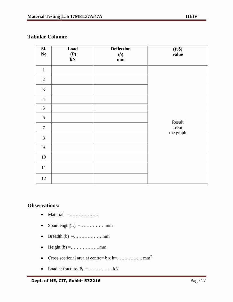
Tabular Column:
Sl.
No
Load
(P)
kN
Deflection
()
mm
(P/)
value
1
Result
from
the graph
2
3
4
5
6
7
8
9
10
11
12
Observations:
Material =……………….
Span length(L) =……………..mm
Breadth (b) =……………….mm
Height (h) =……………….mm
Cross sectional area at centre= b x h=…………….. mm2
Load at fracture, Pf =……………..kN
Material Testing Lab 17MEL37A/47A III/IV
Dept. of ME, CIT, Gubbi- 572216 Page 18
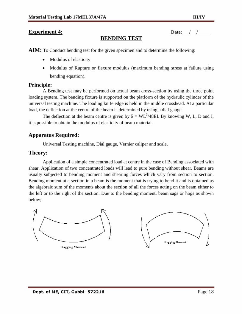
Experiment 4: Date: __ /__ / _____
BENDING TEST
AIM: To Conduct bending test for the given specimen and to determine the following:
Modulus of elasticity
Modulus of Rupture or flexure modulus (maximum bending stress at failure using
bending equation).
Principle: A Bending test may be performed on actual beam cross-section by using the three point
loading system. The bending fixture is supported on the platform of the hydraulic cylinder of the
universal testing machine. The loading knife edge is held in the middle crosshead. At a particular
load, the deflection at the centre of the beam is determined by using a dial gauge.
The deflection at the beam centre is given by = WL3/48EI. By knowing W, L, D and I,
it is possible to obtain the modulus of elasticity of beam material.
Apparatus Required:
Universal Testing machine, Dial gauge, Vernier caliper and scale.
Theory:
Application of a simple concentrated load at centre in the case of Bending associated with
shear. Application of two concentrated loads will lead to pure bending without shear. Beams are
usually subjected to bending moment and shearing forces which vary from section to section.
Bending moment at a section in a beam is the moment that is trying to bend it and is obtained as
the algebraic sum of the moments about the section of all the forces acting on the beam either to
the left or to the right of the section. Due to the bending moment, beam sags or hogs as shown
below;
Material Testing Lab 17MEL37A/47A III/IV
Dept. of ME, CIT, Gubbi- 572216 Page 19
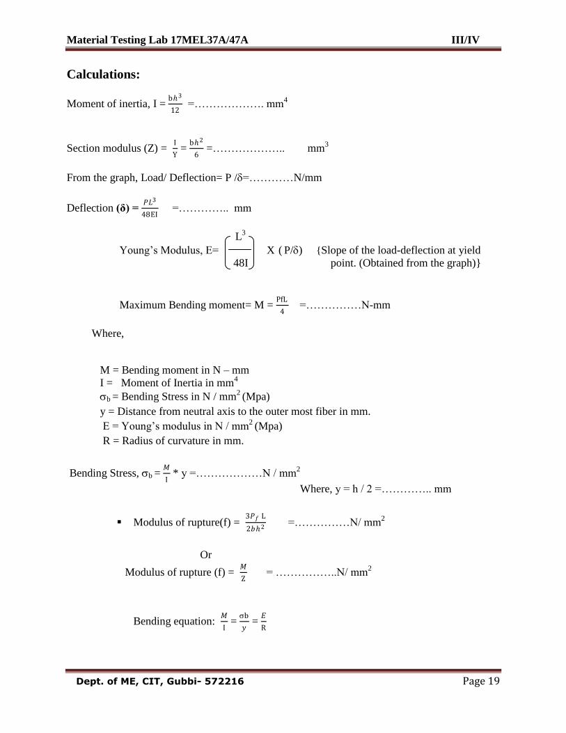
Calculations:
Moment of inertia, I = bℎ3
12 =………………. mm
4
Section modulus (Z) = I
Y =
bℎ2
6 =………………..
mm
3
From the graph, Load/ Deflection= P /=…………N/mm
Deflection (δ) = 𝑃𝐿3
48EI =………….. mm
L3
Young‟s Modulus, E=
X ( P/) {Slope of the load-deflection at yield
48I point. (Obtained from the graph)}
Maximum Bending moment= M = PfL
4 =……………N-mm
Where,
M = Bending moment in N – mm I = Moment of Inertia in mm
4
b = Bending Stress in N / mm
2 (Mpa)
y = Distance from neutral axis to the outer most fiber in mm.
E = Young‟s modulus in N / mm2
(Mpa)
R = Radius of curvature in mm.
Bending Stress, b = 𝑀
I * y =………………N / mm
2
Where, y = h / 2 =………….. mm
Modulus of rupture(f) = 3𝑃𝑓 L
2𝑏ℎ2 =……………N/ mm2
Or
Modulus of rupture (f) = 𝑀
Z = ……………..N/ mm
2
Bending equation: 𝑀
I =
b
𝑦 =
𝐸
R
Material Testing Lab 17MEL37A/47A III/IV
Dept. of ME, CIT, Gubbi- 572216 Page 20
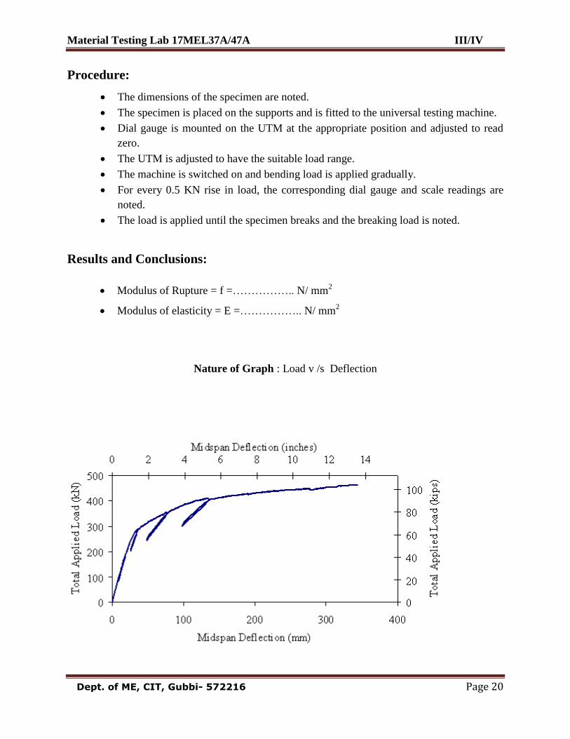
Procedure:
The dimensions of the specimen are noted.
The specimen is placed on the supports and is fitted to the universal testing machine.
Dial gauge is mounted on the UTM at the appropriate position and adjusted to read
zero.
The UTM is adjusted to have the suitable load range.
The machine is switched on and bending load is applied gradually.
For every 0.5 KN rise in load, the corresponding dial gauge and scale readings are
noted.
The load is applied until the specimen breaks and the breaking load is noted.
Results and Conclusions:
Modulus of Rupture = f =…………….. N/ mm2
Modulus of elasticity = E =…………….. N/ mm2
Nature of Graph : Load v /s Deflection
Material Testing Lab 17MEL37A/47A III/IV
Dept. of ME, CIT, Gubbi- 572216 Page 21
Material Testing Lab 17MEL37A/47A III/IV
Dept. of ME, CIT, Gubbi- 572216 Page 22
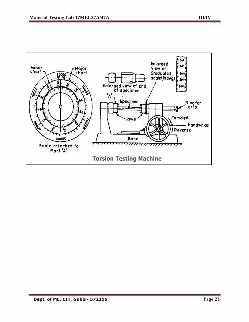
Experiment 5: Date: __ /__ / _____
TORSION TEST
AIM: To determine the modulus of rigidity and torsional shear stresses developed
Apparatus: Torsion Testing machine, Vernier Calipers, Measuring scale, Specimen etc.
Theory: Torsion of circular shafts
Definition of Torsion: Consider a shaft rigidly clamped at one end and twisted at the other end
by a torque T = F.d applied in a plane perpendicular to the axis of the bar such a shaft is said to
be in torsion.
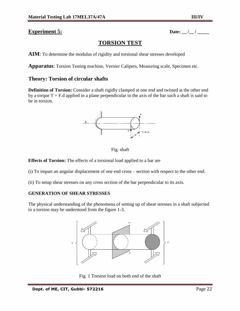
Fig. shaft
Effects of Torsion: The effects of a torsional load applied to a bar are
(i) To impart an angular displacement of one end cross – section with respect to the other end.
(ii) To setup shear stresses on any cross section of the bar perpendicular to its axis.
GENERATION OF SHEAR STRESSES
The physical understanding of the phenomena of setting up of shear stresses in a shaft subjected
to a torsion may be understood from the figure 1-3.
Fig. 1 Torsion load on both end of the shaft
Material Testing Lab 17MEL37A/47A III/IV
Dept. of ME, CIT, Gubbi- 572216 Page 23
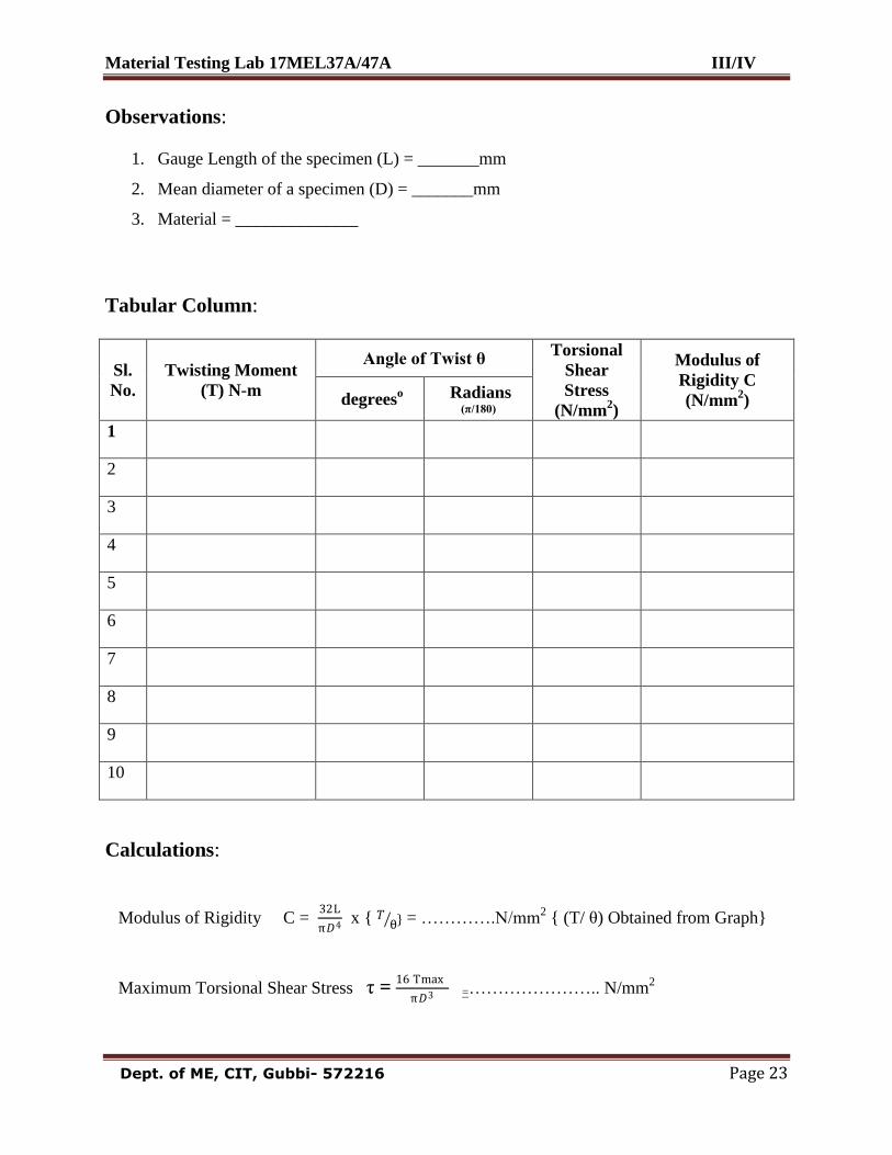
Observations:
1. Gauge Length of the specimen (L) = _______mm
2. Mean diameter of a specimen (D) = _______mm
3. Material = ______________
Tabular Column:
Sl.
No.
Twisting Moment
(T) N-m
Angle of Twist θ Torsional
Shear
Stress
(N/mm2)
Modulus of
Rigidity C
(N/mm2) degrees
o Radians (π/180)
1
2
3
4
5
6
7
8
9
10
Calculations:
Modulus of Rigidity C = 32L
π𝐷4 x { 𝑇 θ } = ………….N/mm
2 { (T/ θ) Obtained from Graph}
Maximum Torsional Shear Stress τ = 16 Tmax
π𝐷3 =………………….. N/mm
2
Material Testing Lab 17MEL37A/47A III/IV
Dept. of ME, CIT, Gubbi- 572216 Page 24
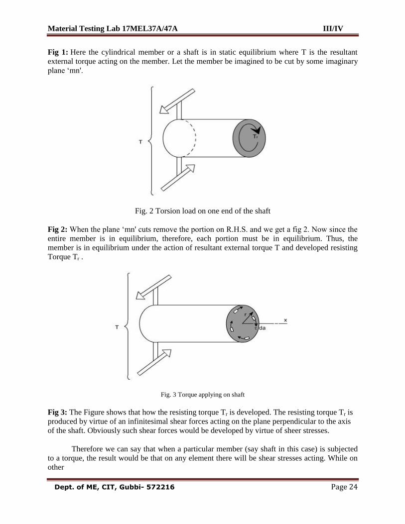
Fig 1: Here the cylindrical member or a shaft is in static equilibrium where T is the resultant
external torque acting on the member. Let the member be imagined to be cut by some imaginary
plane „mn'.
Fig. 2 Torsion load on one end of the shaft
Fig 2: When the plane „mn' cuts remove the portion on R.H.S. and we get a fig 2. Now since the
entire member is in equilibrium, therefore, each portion must be in equilibrium. Thus, the
member is in equilibrium under the action of resultant external torque T and developed resisting
Torque Tr .
Fig. 3 Torque applying on shaft
Fig 3: The Figure shows that how the resisting torque Tr is developed. The resisting torque Tr is
produced by virtue of an infinitesimal shear forces acting on the plane perpendicular to the axis
of the shaft. Obviously such shear forces would be developed by virtue of sheer stresses.
Therefore we can say that when a particular member (say shaft in this case) is subjected
to a torque, the result would be that on any element there will be shear stresses acting. While on
other

Material Testing Lab 17MEL37A/47A III/IV
Dept. of ME, CIT, Gubbi- 572216 Page 25
Material Testing Lab 17MEL37A/47A III/IV
Dept. of ME, CIT, Gubbi- 572216 Page 26
faces the complementary sheer forces come into picture. Thus, we can say that when a member is
subjected to torque, an element of this member will be subjected to a state of pure shear.
Shaft: The shafts are the machine elements which are used to transmit power in machines.
Twisting Moment: The twisting moment for any section along the bar / shaft is defined to be the
algebraic sum of the moments of the applied couples that lie to one side of the section under
consideration. The choice of the side in any case is of course arbitrary.
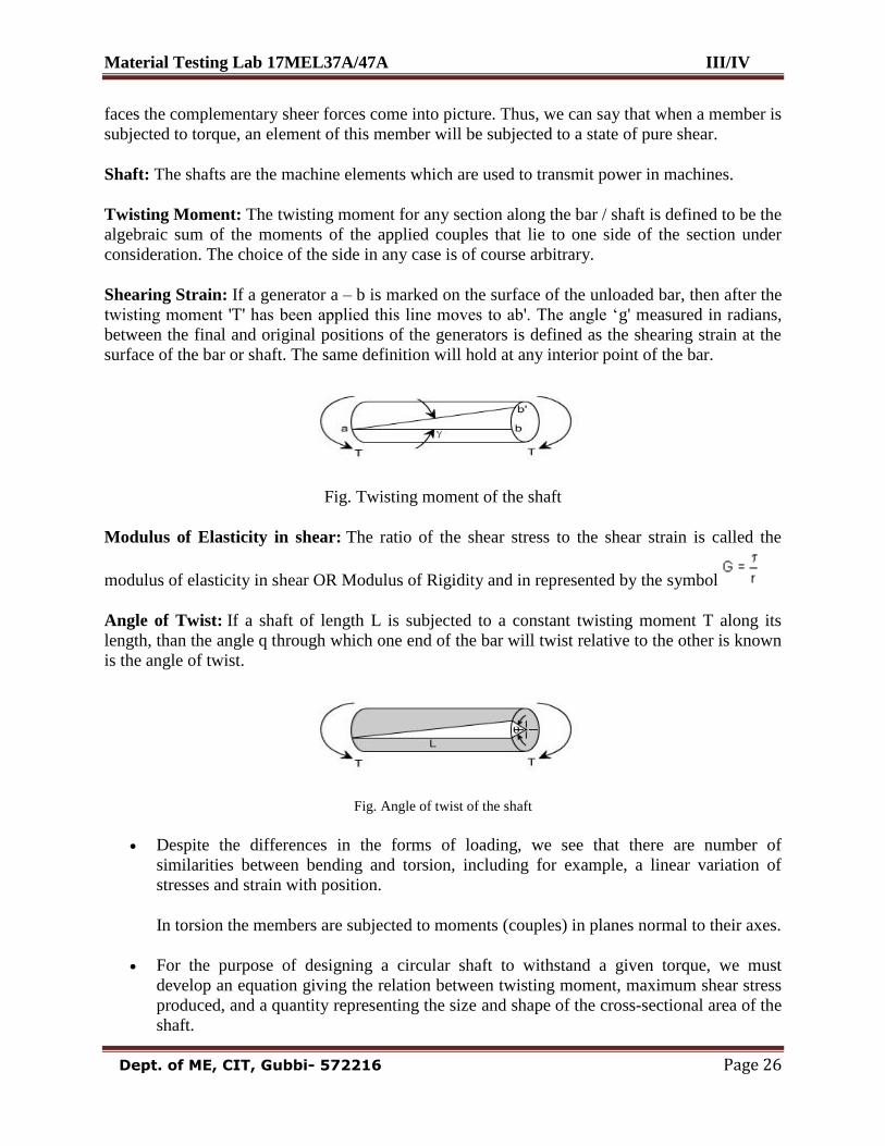
Shearing Strain: If a generator a – b is marked on the surface of the unloaded bar, then after the
twisting moment 'T' has been applied this line moves to ab'. The angle „g' measured in radians,
between the final and original positions of the generators is defined as the shearing strain at the
surface of the bar or shaft. The same definition will hold at any interior point of the bar.
Fig. Twisting moment of the shaft
Modulus of Elasticity in shear: The ratio of the shear stress to the shear strain is called the
modulus of elasticity in shear OR Modulus of Rigidity and in represented by the symbol
Angle of Twist: If a shaft of length L is subjected to a constant twisting moment T along its
length, than the angle q through which one end of the bar will twist relative to the other is known
is the angle of twist.
Fig. Angle of twist of the shaft
Despite the differences in the forms of loading, we see that there are number of
similarities between bending and torsion, including for example, a linear variation of
stresses and strain with position.
In torsion the members are subjected to moments (couples) in planes normal to their axes.
For the purpose of designing a circular shaft to withstand a given torque, we must
develop an equation giving the relation between twisting moment, maximum shear stress
produced, and a quantity representing the size and shape of the cross-sectional area of the
shaft.
Material Testing Lab 17MEL37A/47A III/IV
Dept. of ME, CIT, Gubbi- 572216 Page 27
Material Testing Lab 17MEL37A/47A III/IV
Dept. of ME, CIT, Gubbi- 572216 Page 28
Procedure:
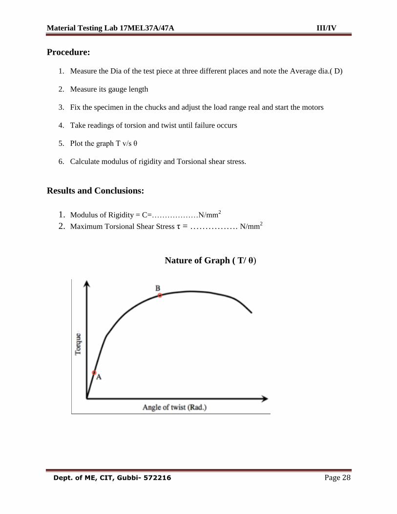
1. Measure the Dia of the test piece at three different places and note the Average dia.( D)
2. Measure its gauge length
3. Fix the specimen in the chucks and adjust the load range real and start the motors
4. Take readings of torsion and twist until failure occurs
5. Plot the graph T v/s θ
6. Calculate modulus of rigidity and Torsional shear stress.
Results and Conclusions:
1. Modulus of Rigidity = C=………………N/mm2
2. Maximum Torsional Shear Stress τ = ……………. N/mm2
Nature of Graph ( T/ θ)
Material Testing Lab 17MEL37A/47A III/IV
Dept. of ME, CIT, Gubbi- 572216 Page 29
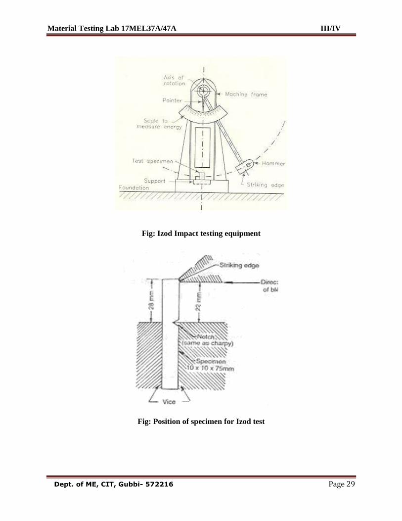
Fig: Izod Impact testing equipment
Fig: Position of specimen for Izod test
Material Testing Lab 17MEL37A/47A III/IV
Dept. of ME, CIT, Gubbi- 572216 Page 30
Experiment 6: Date: __ /__ / _____ IZOD IMPACT TEST
AIM: To determine the Impact strength (Specific impact factor) through Izod test.
Principle: Static tests are not satisfactory in determining the resistance to shock or impact
loads such as automobile parts are subjected to shock loads, and in the impact test a notched
specimen of the material is fractured by a single blow from a heavy hammer, the energy required
being a measure of the resistance to impact.
Materials and Equipments Required:
Impact testing machine, MS Specimen
Theory:
Izod Impact Test:
A pendulum type single blow impact test in which the specimen, usually notched, is fixed
at one end and free at other end as a cantilever beam. Specimen is broken by a falling pendulum.
The energy absorbed as measured by the subsequent rise of the pendulum is a measure of impact
strength or notch toughness.
Notch: A slot or groove of specified characteristics intentionally cut in a test piece so as to
concentrate the stress localizing the rupture.
Notch Toughness: The high resistance of the material to fracture under suddenly applied loads
at any Stress raiser such as notch.
Toughness: The ability of the material to absorb energy and deform plastically before fracture. It
is usually measured by the energy absorbed in a notched impact test like Charpy and Izod tests.
The area under the stress -strain curve in a tensile test is also a measure of toughness and as such
is proportional to the combined effects of tensile strength and ductility.
The Izod impact energy (I) i.e., the energy required to break the specimen is obtained
directly from the test. The depth below the notch and the breadth of the specimen is measured
(i.e. d and b). The effective cross-sectional area below the notch is obtained (A=bd mm2) hence,
specific Impact factor=If=I/A Joules /mm2
Material Testing Lab 17MEL37A/47A III/IV
Dept. of ME, CIT, Gubbi- 572216 Page 31
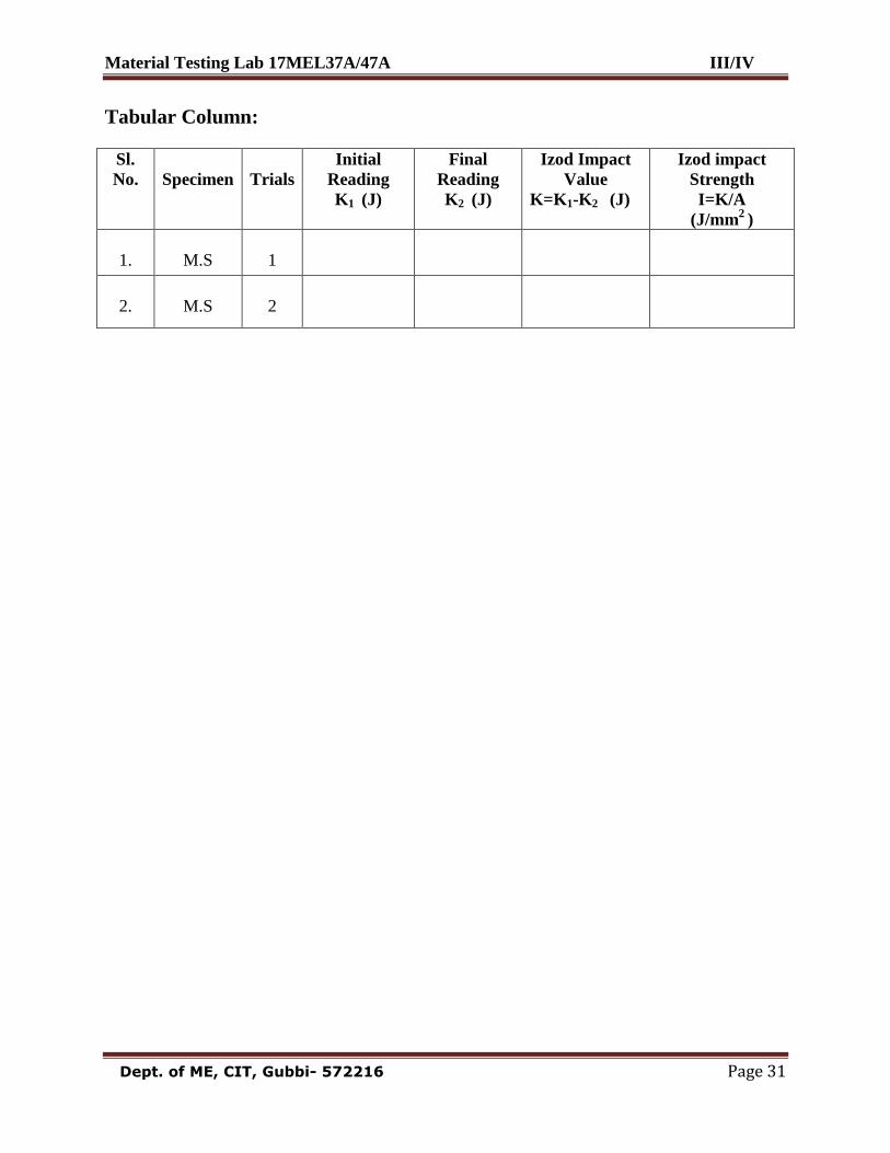
Tabular Column:
Sl.
No.
Specimen
Trials
Initial
Reading
K1 (J)
Final
Reading
K2 (J)
Izod Impact
Value
K=K1-K2 (J)
Izod impact
Strength
I=K/A
(J/mm2
)
1.
M.S
1
2.
M.S
2
Material Testing Lab 17MEL37A/47A III/IV
Dept. of ME, CIT, Gubbi- 572216 Page 32
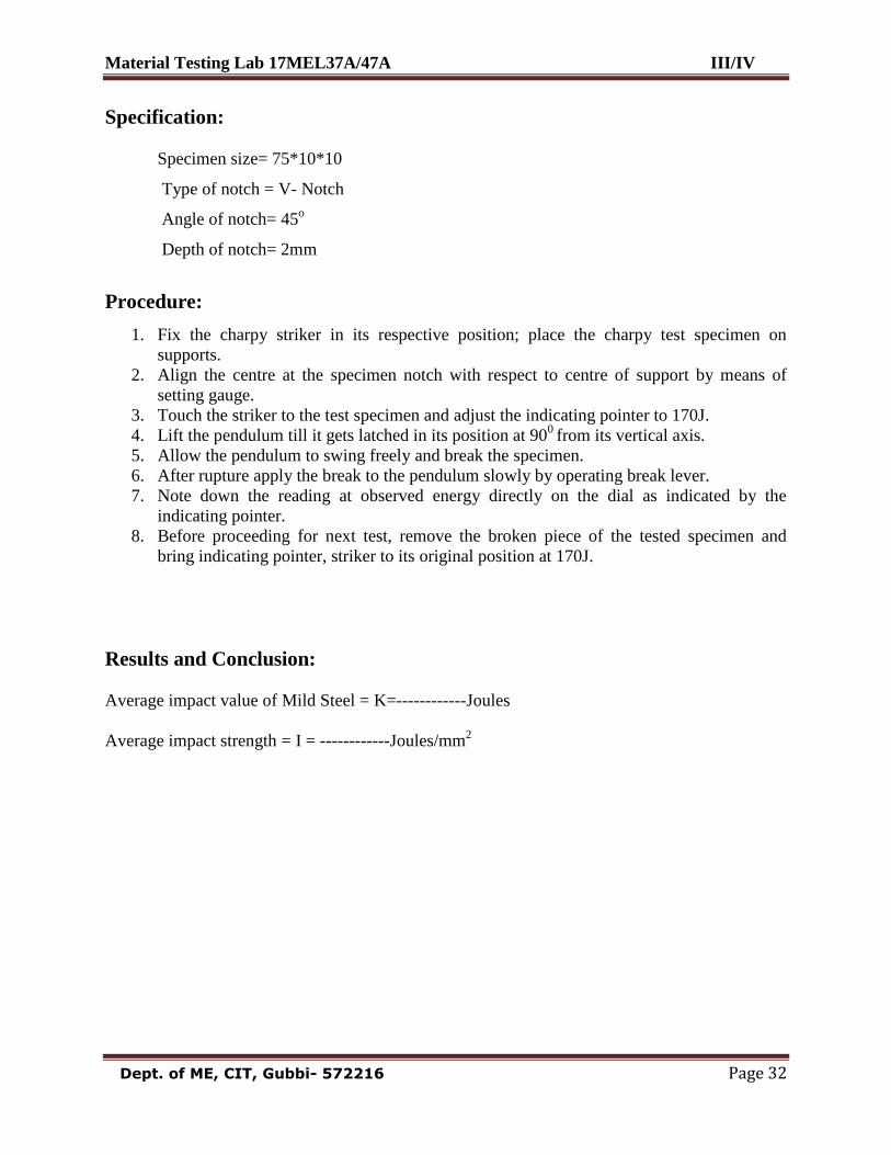
Specification:
Specimen size= 75*10*10
Type of notch = V- Notch
Angle of notch= 45o
Depth of notch= 2mm
Procedure:
1. Fix the charpy striker in its respective position; place the charpy test specimen on
supports.
2. Align the centre at the specimen notch with respect to centre of support by means of
setting gauge.
3. Touch the striker to the test specimen and adjust the indicating pointer to 170J.
4. Lift the pendulum till it gets latched in its position at 900
from its vertical axis.
5. Allow the pendulum to swing freely and break the specimen.
6. After rupture apply the break to the pendulum slowly by operating break lever.
7. Note down the reading at observed energy directly on the dial as indicated by the
indicating pointer.
8. Before proceeding for next test, remove the broken piece of the tested specimen and
bring indicating pointer, striker to its original position at 170J.
Results and Conclusion:
Average impact value of Mild Steel = K=------------Joules
Average impact strength = I = ------------Joules/mm2
Material Testing Lab 17MEL37A/47A III/IV
Dept. of ME, CIT, Gubbi- 572216 Page 33
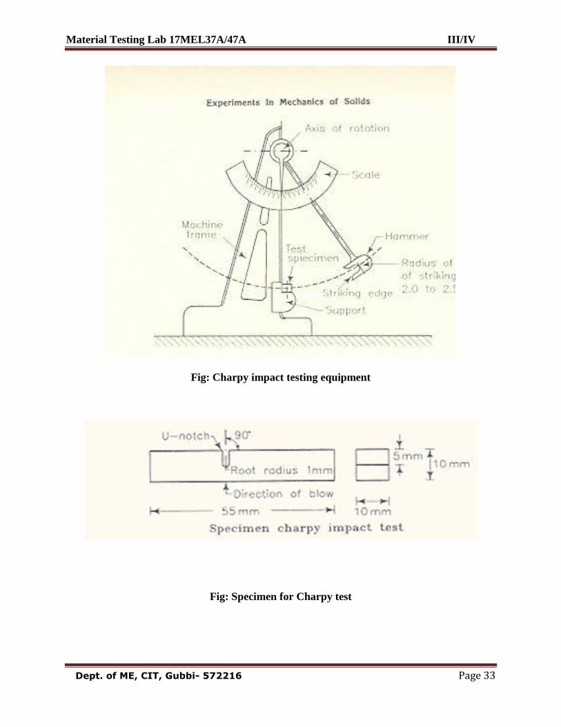
Fig: Charpy impact testing equipment
Fig: Specimen for Charpy test
Material Testing Lab 17MEL37A/47A III/IV
Dept. of ME, CIT, Gubbi- 572216 Page 34
Experiment 7: Date: __ /__ / _____ CHARPY TEST
AIM: To determine the Impact strength (Specific impact factor) through Charpy test.
Principle:
The Charpy Impact Test is similar in principle to the Izod, but the notched specimen is
supported at each end as a simply supported beam and struck by the hammer in the centre.
Materials and equipments required:
Impact testing machine, MS Specimen
Theory:
In an impact test a specially prepared notched specimen is fractured by a single blow
from a heavy hammer and energy required being a measure of resistance to Impact. Impact load
is produced by a swinging of an impact weight (hammer) from a height. Release of the weight
from the height swings the weight through the arc of a circle, which strikes the specimen to
fracture at the notch. Here it is interesting to note that height through which hammer drops
determines the velocity and height and mass of a hammer combined determine the energy.
Energy used can be measured from the scale given. The difference between potential energies is
the fracture energy. In test machine this value indicated by the pointer on the scale. This energy
value called impact toughness or impact value, which will be measured, per unit area at the
notch.
Specification:
Specimen size= 55*10*10
Type of notch = U – Notch
Angle of notch= 45o
Depth of notch= 2mm
Material Testing Lab 17MEL37A/47A III/IV
Dept. of ME, CIT, Gubbi- 572216 Page 35
Tabular Column:
Sl.
No.
Specimen
Trials
Initial
Reading
K1 (J)
Final
Reading
K2 (J)
Charpy
Impact
Value
K=K1-K2
(J)
Charpy
impact
Strength
I=K/A
(J/Cm2
)
1.
M.S
1
2.
M.S
2
Material Testing Lab 17MEL37A/47A III/IV
Dept. of ME, CIT, Gubbi- 572216 Page 36
Procedure:
1. Fix the charpy striker in its respective position; place the charpy test specimen on
supports.
2. Align the centre at the specimen notch with respect to centre of support by means of
setting gauge.
3. Touch the striker to the test specimen and adjust the indicating pointer to 300J.
4. Lift the pendulum till it gets latched in its position at 1400
from its vertical axis.
5. Allow the pendulum to swing freely and break the specimen.
6. After rupture apply the break to the pendulum slowly by operating break lever.
7. Note down the reading at observed energy directly on the dial as indicated by the
indicating pointer.
8. Before proceeding for next test, remove the broken piece of the tested specimen and
bring indicating pointer, striker to its original position at 300J.
Results and Conclusion:
Average impact value of Mild Steel = K= ------------Joules Average impact strength = I =------------Joules/cm
2
Material Testing Lab 17MEL37A/47A III/IV
Dept. of ME, CIT, Gubbi- 572216 Page 37
Observation:
Type of specimen Type of Indenter Scale Total load(P)
Kg-F
Hard Metals Diamond cone C (Black graduations) 150
Soft Metals Ball (1/16”) B (Red graduations ) 100
Tabular Column:
Sl.No Specimen Type of
Indenter
RHN Average
RHN 1 2 3
01 Hardened steel Diamond
cone
02 Mild steel Ball (1/16”)
03 Brass Ball (1/16”)
04 Copper Ball (1/16”)
05 Aluminium Ball (1/16”)
Material Testing Lab 17MEL37A/47A III/IV
Dept. of ME, CIT, Gubbi- 572216 Page 38
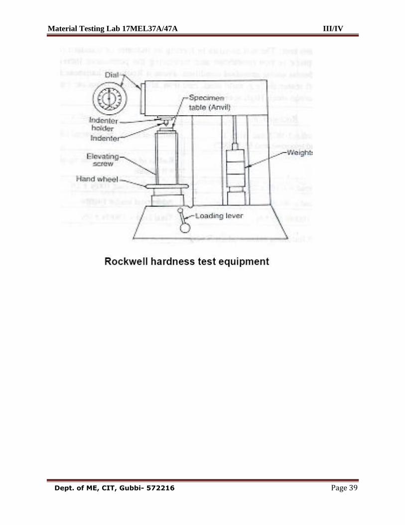
Experiment 8: Date: __ /__ / _____ ROCKWELL HARDNESS TEST
AIM: To determine the Rockwell hardness number of the given Specimen using “Rockwell
Hardness tester”.
Principle: A standard load (Based on type of material) is applied through a standard indentor
(cone or ball indenter) for a standard duration of time. The hardness number is directly obtained
in the experiment.
Practical importance: Hardness is the property of the material by which it offers resistance
to scratch or indentation. It is the most important property, as the material is subjected to friction
and scratch. By this experiment we can determine the Hardness of the given material.
Materials and equipments required:
Rockwell hardness testing machine.
Diamond cone indentor, ball indentor.
Specimens (Hardened steel, Mild steel, Brass, Copper, Aluminium )
Theory:
Hardness of a material is generally defined as Resistance to the permanent indentation
under static and dynamic load. When a material is required to use under direct static or dynamic
loads, only indentation hardness test will be useful to find out resistance to indentation.
Rockwell test is developed by the Wilson instrument co U.S.A in 1920. This test is an
indentation test used for smaller specimens and harder materials. In this test indentor is forced
into the surface of a test piece in two operations, measuring the permanent increase in depth of
an indentation from the depth increased from the depth reached under a datum load due to an
additional load.
Measurement of indentation is made after removing the additional load. Indentor used is
the cone having an angle of 120 degrees made of black diamond.
Material Testing Lab 17MEL37A/47A III/IV
Dept. of ME, CIT, Gubbi- 572216 Page 39
Material Testing Lab 17MEL37A/47A III/IV
Dept. of ME, CIT, Gubbi- 572216 Page 40
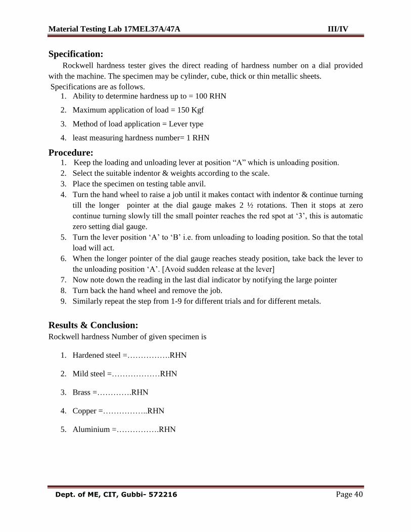
Specification:
Rockwell hardness tester gives the direct reading of hardness number on a dial provided
with the machine. The specimen may be cylinder, cube, thick or thin metallic sheets.
Specifications are as follows.
1. Ability to determine hardness up to = 100 RHN
2. Maximum application of load = 150 Kgf
3. Method of load application = Lever type
4. least measuring hardness number= 1 RHN
Procedure: 1. Keep the loading and unloading lever at position “A” which is unloading position.
2. Select the suitable indentor & weights according to the scale.
3. Place the specimen on testing table anvil.
4. Turn the hand wheel to raise a job until it makes contact with indentor & continue turning
till the longer pointer at the dial gauge makes 2 ½ rotations. Then it stops at zero
continue turning slowly till the small pointer reaches the red spot at „3‟, this is automatic
zero setting dial gauge.
5. Turn the lever position „A‟ to „B‟ i.e. from unloading to loading position. So that the total
load will act.
6. When the longer pointer of the dial gauge reaches steady position, take back the lever to
the unloading position „A‟. [Avoid sudden release at the lever]
7. Now note down the reading in the last dial indicator by notifying the large pointer
8. Turn back the hand wheel and remove the job.
9. Similarly repeat the step from 1-9 for different trials and for different metals.
Results & Conclusion:
Rockwell hardness Number of given specimen is
1. Hardened steel =…………….RHN
2. Mild steel =………………RHN
3. Brass =………….RHN
4. Copper =……………..RHN
5. Aluminium =…………….RHN
Material Testing Lab 17MEL37A/47A III/IV
Dept. of ME, CIT, Gubbi- 572216 Page 41
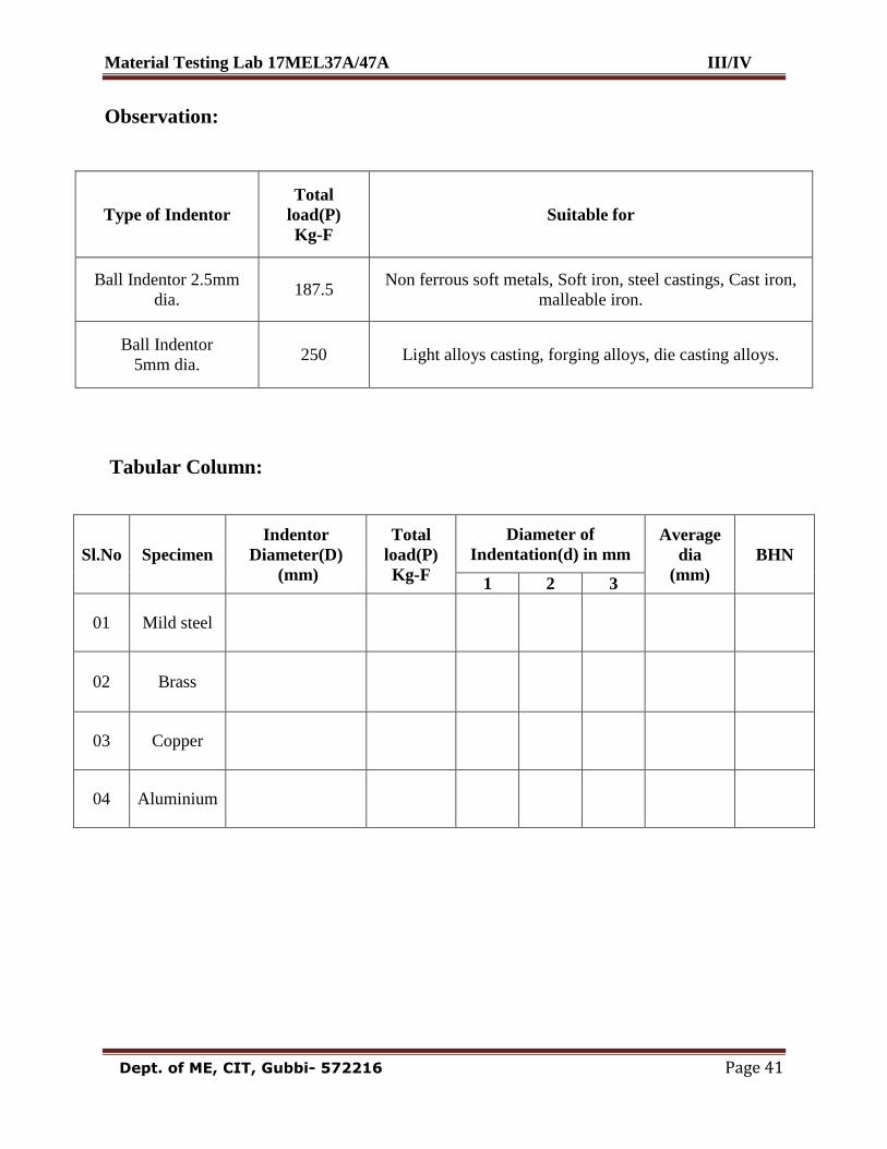
Observation:
Type of Indentor
Total
load(P)
Kg-F
Suitable for
Ball Indentor 2.5mm
dia. 187.5
Non ferrous soft metals, Soft iron, steel castings, Cast iron,
malleable iron.
Ball Indentor
5mm dia. 250 Light alloys casting, forging alloys, die casting alloys.
Tabular Column:
Sl.No Specimen
Indentor
Diameter(D)
(mm)
Total
load(P)
Kg-F
Diameter of
Indentation(d) in mm
Average
dia
(mm)
BHN
1 2 3
01 Mild steel
02 Brass
03 Copper
04 Aluminium
Material Testing Lab 17MEL37A/47A III/IV
Dept. of ME, CIT, Gubbi- 572216 Page 42
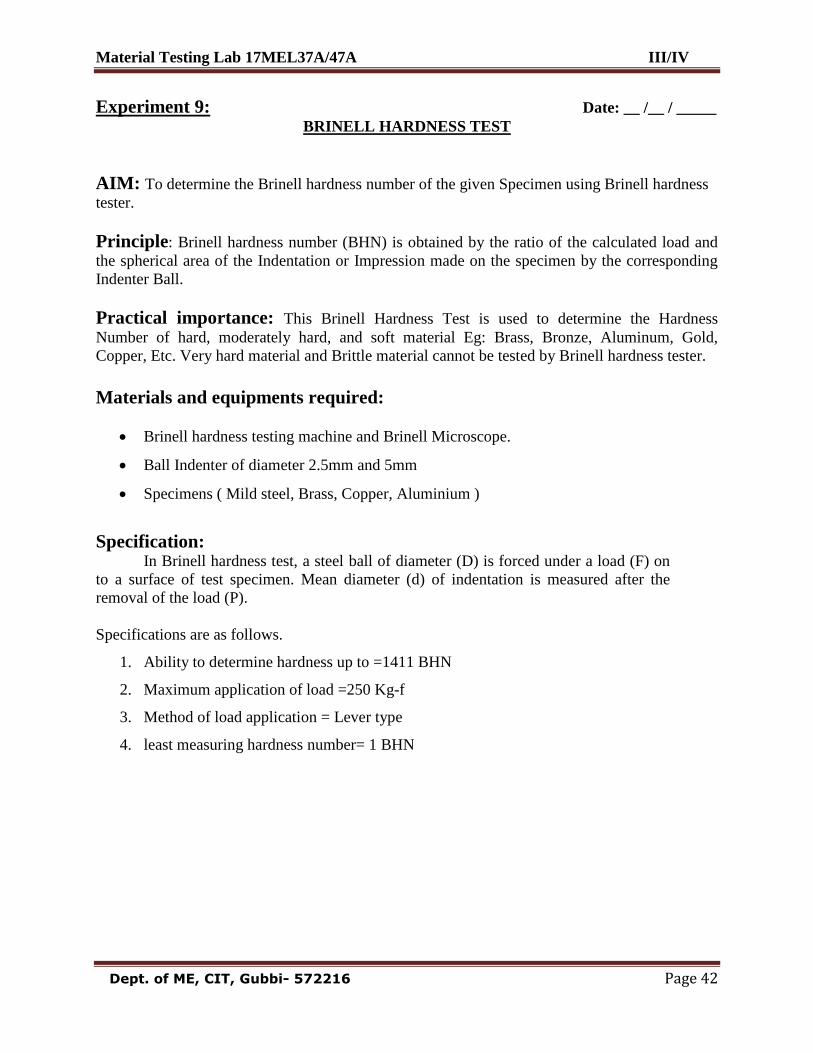
Experiment 9: Date: __ /__ / _____
BRINELL HARDNESS TEST
AIM: To determine the Brinell hardness number of the given Specimen using Brinell hardness
tester.
Principle: Brinell hardness number (BHN) is obtained by the ratio of the calculated load and
the spherical area of the Indentation or Impression made on the specimen by the corresponding
Indenter Ball.
Practical importance: This Brinell Hardness Test is used to determine the Hardness
Number of hard, moderately hard, and soft material Eg: Brass, Bronze, Aluminum, Gold,
Copper, Etc. Very hard material and Brittle material cannot be tested by Brinell hardness tester.
Materials and equipments required:
Brinell hardness testing machine and Brinell Microscope.
Ball Indenter of diameter 2.5mm and 5mm
Specimens ( Mild steel, Brass, Copper, Aluminium )
Specification: In Brinell hardness test, a steel ball of diameter (D) is forced under a load (F) on
to a surface of test specimen. Mean diameter (d) of indentation is measured after the
removal of the load (P).
Specifications are as follows.
1. Ability to determine hardness up to =1411 BHN
2. Maximum application of load =250 Kg-f
3. Method of load application = Lever type
4. least measuring hardness number= 1 BHN
Material Testing Lab 17MEL37A/47A III/IV
Dept. of ME, CIT, Gubbi- 572216 Page 43
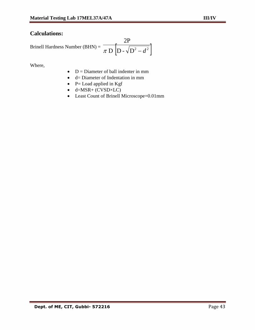
Calculations:
Brinell Hardness Number (BHN) = 22D-D D
2P
d
Where,
D = Diameter of ball indenter in mm
d= Diameter of Indentation in mm
P= Load applied in Kgf
d=MSR+ (CVSD×LC)
Least Count of Brinell Microscope=0.01mm
Material Testing Lab 17MEL37A/47A III/IV
Dept. of ME, CIT, Gubbi- 572216 Page 44
Procedure:
1. Keep the loading and unloading lever at position “A” which is unloading position.
2. Select the suitable indenter & weights according to the scale.
3. Place the specimen on testing table anvil.
4. Turn the hand wheel to raise a job until it makes contact with indenter & continue turning
till the longer pointer at the dial gauge makes 2 ½ rotations. Then it stops at zero
continue turning slowly till the small pointer reaches the red spot at „3‟, this is automatic
zero setting dial gauge.
5. Turn the lever position „A‟ to „B‟ i.e. from unloading to loading position. So that the total
load will act.
6. When the longer pointer of the dial gauge reaches steady position, take back the lever to
the unloading position „A‟. [Avoid sudden release at the lever]
7. Remove the job from the platform and note down the diameter of the indentation using
Brinell microscope.
8. Using appropriate formula calculate BHN.
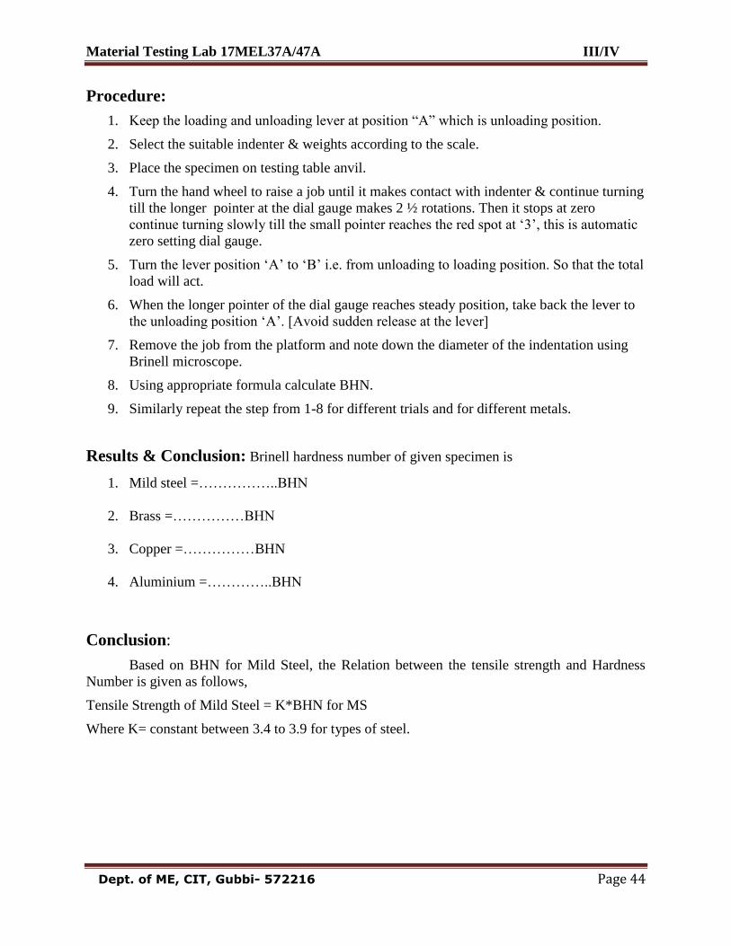
9. Similarly repeat the step from 1-8 for different trials and for different metals.
Results & Conclusion: Brinell hardness number of given specimen is
1. Mild steel =……………..BHN
2. Brass =……………BHN
3. Copper =……………BHN
4. Aluminium =…………..BHN
Conclusion:
Based on BHN for Mild Steel, the Relation between the tensile strength and Hardness
Number is given as follows,
Tensile Strength of Mild Steel = K*BHN for MS
Where K= constant between 3.4 to 3.9 for types of steel.
Material Testing Lab 17MEL37A/47A III/IV
Dept. of ME, CIT, Gubbi- 572216 Page 45
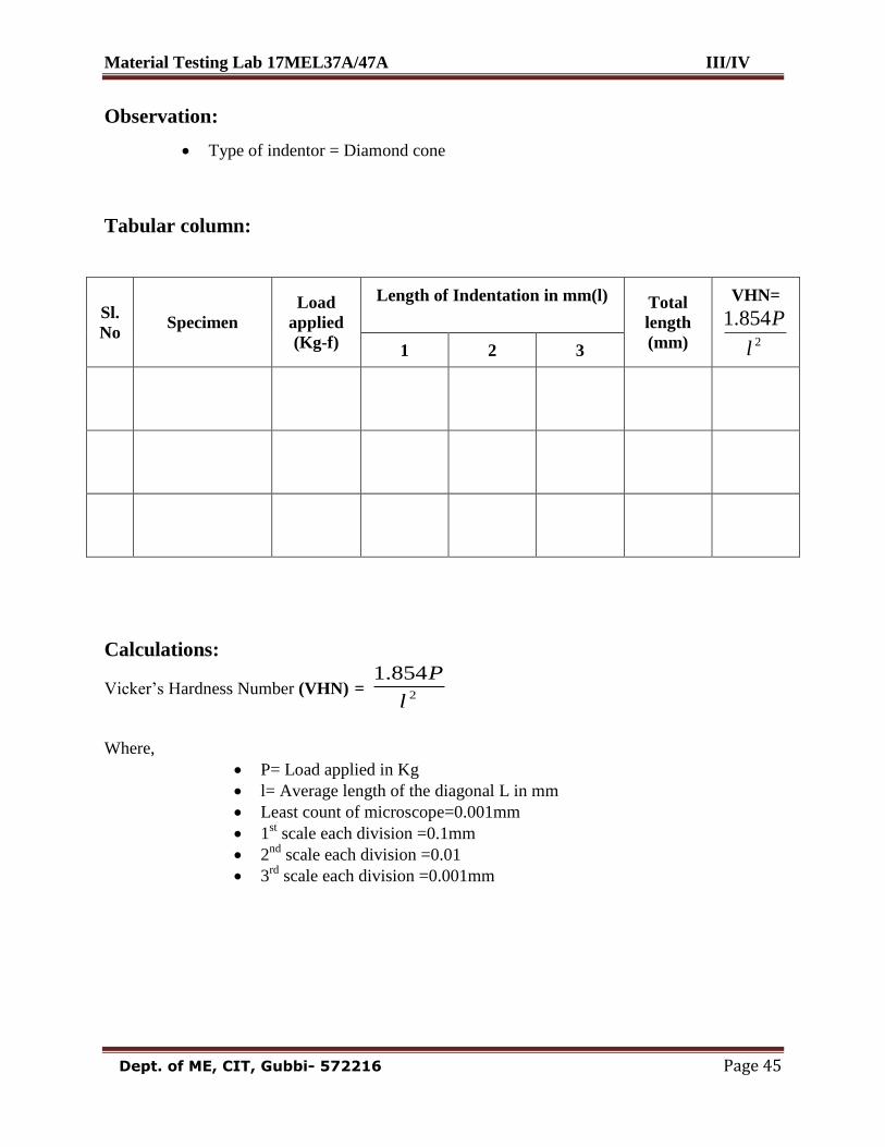
Observation:
Type of indentor = Diamond cone
Tabular column:
Sl.
No Specimen
Load
applied
(Kg-f)
Length of Indentation in mm(l)
Total
length
(mm)
VHN=
2
854.1
l
P
1 2 3
Calculations:
Vicker‟s Hardness Number (VHN) = 2
854.1
l
P
Where,
P= Load applied in Kg
l= Average length of the diagonal L in mm
Least count of microscope=0.001mm
1st scale each division =0.1mm
2nd
scale each division =0.01
3rd
scale each division =0.001mm
Material Testing Lab 17MEL37A/47A III/IV
Dept. of ME, CIT, Gubbi- 572216 Page 46
Experiment 10: Date: __ /__ / _____
VICKER’S HARDNESS TEST
AIM: To determine the hardness of the given Specimen using Vicker‟s hardness test.
Principle: The required load as calculated by P/D2 ratio is applied on the specimen for a
standard time of 8-10 Sec‟s and BHN is calculated by the ratio of load and the spherical area of
indentation. The diameter of the indentation is measured on the focusing screen of the machine.
Practical Importance :
Hardness is the property of the material by which it offers resistance to scratch or
indentation. It is the most important property, as the material is subjected to friction and scratch.
By this experiment we can determine the Hardness of the given material.
Materials And Equipments Required: Vicker‟s Hardness Testing Machine.
Diamond cone indentor,
Specimen.
Theory: Very Hard materials (e.g. Mild steel, case hardened steel, etc,) can be tested by the
Vickers‟s method. If the moderately hard materials like Brass, Copper and Aluminium are tested
in this machine, the indentor makes a deep impression. Hence, a proper indentation cannot be
made on the specimen and a correct value of the hardness cannot be obtained for these materials
by V. H. Test.
VHN = Load Sloping or pyramidal area of indentation
This test is similar to Brinell hardness test similar relationship and eliminates most of the
errors. A regular pyramid having a square base and smoothened off diamond point is pressed in
the material to be tested under a load „F‟. The produced impression is projected onto a focusing
screen and the diagonals of the impression are measured by means of the measuring equipment.
Due to small impressions, it is very suitable for testing polished and hardened material surfaces.
This test is rapid, accurate.

Material Testing Lab 17MEL37A/47A III/IV
Dept. of ME, CIT, Gubbi- 572216 Page 47
Material Testing Lab 17MEL37A/47A III/IV
Dept. of ME, CIT, Gubbi- 572216 Page 48
Specification:
1 Maximum application of load = 50 kg-f
2 Method of load application = Push button
3 Least measuring indentation length= 0.001mm
Procedure:
1. Clean the surface at the specimen
2. Fix the indenter in the hardness tester and switch on the power supply.
3. Place the specimen with cleaned surface facing the indenter on the anvil at work table.
4. Focus the work piece surface for clean visibility by rotating the hand wheel at the work
table upwards and downwards.
5. Select the load specified (P) push button available on the right side at the hardness tester.
6. Actuate the electric push button (Green Button) at the front for loading, the loading lever
starts moving up words and reaches the study position.
7. Now release the loading lever slowly and bring it to the downward position.
8. For major reading adjust the display at the indentation made by the indenter to coincide
with the micrometer on the display screen.
9. For major (minor) reading adjust the movable side at the micrometer and note down the
total reading.
10. The measurement is to be made for two opposite corners of the diagonal
indentation denoted as (l).
11. Repeat the above procedure for different material.
Results and Conclusion: Vicker‟s hardness Number of given specimen is
1. Mild steel =………………VHN
2. Hardened mild steel =……………..VHN
Material Testing Lab 17MEL37A/47A III/IV
Dept. of ME, CIT, Gubbi- 572216 Page 49
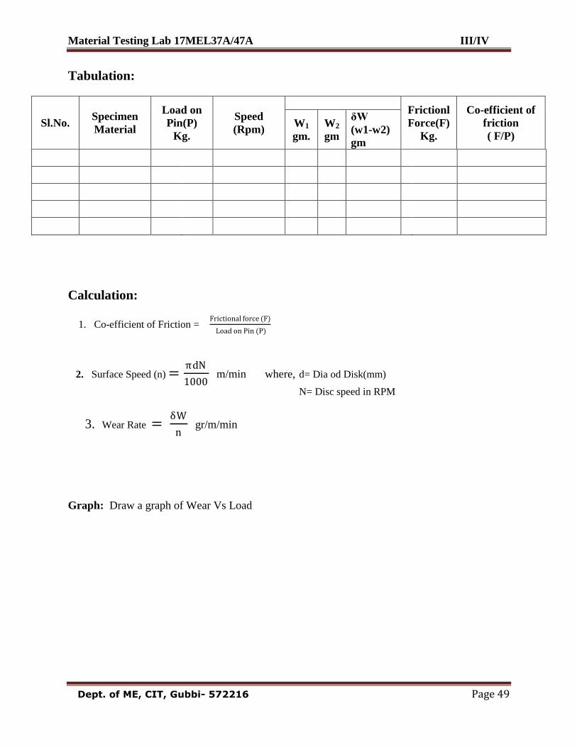
Tabulation:
Sl.No. Specimen
Material
Load on
Pin(P)
Kg.
Speed
(Rpm)
Frictionl
Force(F)
Kg.
Co-efficient of
friction
( F/P)
W1
gm.
W2
gm
δW
(w1-w2)
gm
Calculation:
1. Co-efficient of Friction = Frictional force (F)
Load on Pin (P)
2. Surface Speed (n) =πdN
1000 m/min where, d= Dia od Disk(mm)
N= Disc speed in RPM
3. Wear Rate = δW
n gr/m/min
Graph: Draw a graph of Wear Vs Load
Material Testing Lab 17MEL37A/47A III/IV
Dept. of ME, CIT, Gubbi- 572216 Page 50
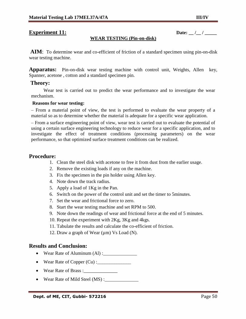
Experiment 11: Date: __ /__ / _____ WEAR TESTING (Pin-on-disk)
AIM: To determine wear and co-efficient of friction of a standard specimen using pin-on-disk
wear testing machine.
Apparatus: Pin-on-disk wear testing machine with control unit, Weights, Allen key,
Spanner, acetone , cotton and a standard specimen pin.
Theory:
Wear test is carried out to predict the wear performance and to investigate the wear
mechanism.
Reasons for wear testing:
– From a material point of view, the test is performed to evaluate the wear property of a
material so as to determine whether the material is adequate for a specific wear application.
– From a surface engineering point of view, wear test is carried out to evaluate the potential of
using a certain surface engineering technology to reduce wear for a specific application, and to
investigate the effect of treatment conditions (processing parameters) on the wear
performance, so that optimized surface treatment conditions can be realized.
Procedure: 1. Clean the steel disk with acetone to free it from dust from the earlier usage.
2. Remove the existing loads if any on the machine.
3. Fix the specimen in the pin holder using Allen key.
4. Note down the track radius.
5. Apply a load of 1Kg in the Pan.
6. Switch on the power of the control unit and set the timer to 5minutes.
7. Set the wear and frictional force to zero.
8. Start the wear testing machine and set RPM to 500.
9. Note down the readings of wear and frictional force at the end of 5 minutes.
10. Repeat the experiment with 2Kg, 3Kg and 4kgs.
11. Tabulate the results and calculate the co-efficient of friction.
12. Draw a graph of Wear (µm) Vs Load (N).
Results and Conclusion:
Wear Rate of Aluminum (Al) :______________
Wear Rate of Copper (Cu) :______________
Wear Rate of Brass :______________
Wear Rate of Mild Steel (MS) :______________
Material Testing Lab 17MEL37A/47A III/IV
Dept. of ME, CIT, Gubbi- 572216 Page 51
Material Testing Lab 17MEL37A/47A III/IV
Dept. of ME, CIT, Gubbi- 572216 Page 52
Experiment 12: Date: __ /__ / _____
NON – DESTRUCTIVE TESTING
A non- destructive test is an examination of a component in any manner which will not
impair its future use. These tests are conducted on various castings and welded joints, to find the
defects inside the castings and the welded joints, without breaking them. Defects like hair – line
crack, sub – surface defect, flaws, internal blow holes etc., can be determined using these
techniques. Some of the non-destructive testing techniques available are:
Magnetic Particle Inspection.
Liquid (Dye) Penetrate Test. Etc.,
Ultrasonic Inspection.
Magnetic Particle Inspection:
Principle of Operation:
When a piece of metal is placed in a magnetic field and the lines of magnetic flux get
intersected by a discontinuity, such as a crack or slag inclusion in a casting, magnetic poles are
induced on either side of the discontinuity. A surface crack is indicated by a line of fine particles
following the crack outline and a subsurface defect by a fuzzy collection of the magnetic
particles on the surface near the discontinuity.
Technique:
Procedural steps involved are:
Magnetizing the component part.
Applying magnetic particles on the component part.
Locating the defects.
Advantages:
Magnetic particle inspection is a relatively simple and easy technique.
It is almost free from any restriction as to size, shape, composition and heat-treatment of
a ferromagnetic specimen.
Limitations:
Suitable only for testing magnetic materials.
Deeper subsurface defects are not satisfactorily detected by this method of
testing.

Material Testing Lab 17MEL37A/47A III/IV
Dept. of ME, CIT, Gubbi- 572216 Page 53
Material Testing Lab 17MEL37A/47A III/IV
Dept. of ME, CIT, Gubbi- 572216 Page 54
Liquid (Dye) Penetrate Test:
Principle of Operation:
The principle of liquid penetrate test is that the liquid used enter the small openings such as
cracks or porosities by Capillary action. The rate and extent of this action are dependent
upon such properties as surface tension, cohesion, adhesion and viscosity.
For the liquid to penetrate effectively, the surface of the material must be thoroughly cleaned
of all material that would obstruct the entrance of the liquid into the defect.
After cleaning, the liquid penetrate is applied evenly over the surface and allowed to remain
long enough to permit penetration into possible discontinuities.
The liquid is then completely removed from the surface and either a wet or dry developer is
applied. The liquid that has penetrated the defect will bleed out onto the surface, and the
developer will help delineate them.
This will show the location and general nature and magnitude of any defect present.
Material Testing Lab 17MEL37A/47A III/IV
Dept. of ME, CIT, Gubbi- 572216 Page 55
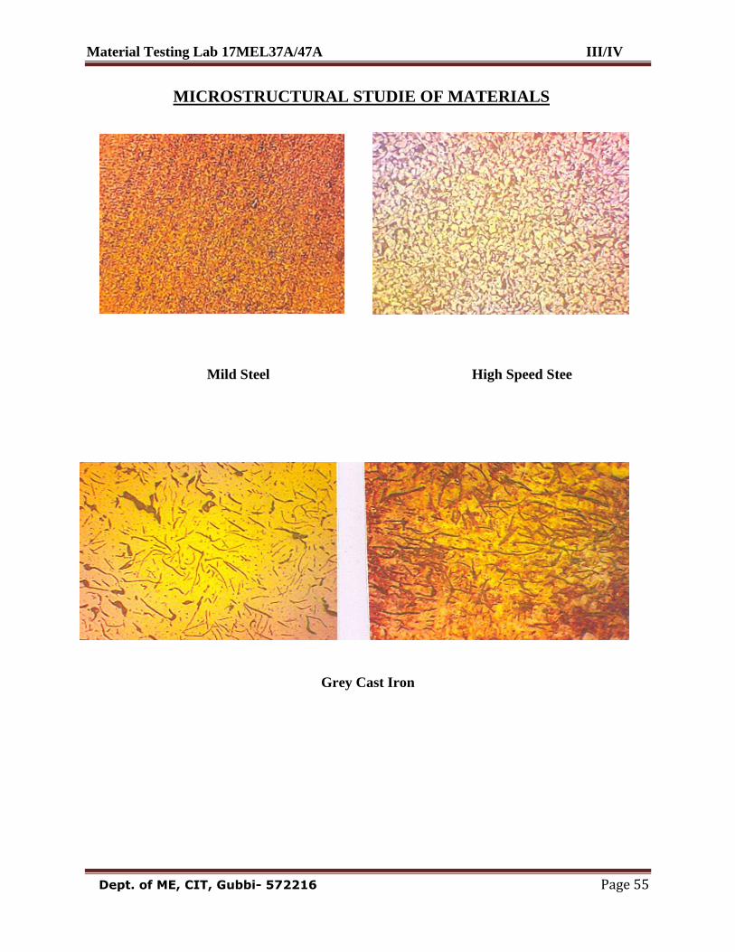
MICROSTRUCTURAL STUDIE OF MATERIALS
Mild Steel High Speed Stee
Grey Cast Iron
Material Testing Lab 17MEL37A/47A III/IV
Dept. of ME, CIT, Gubbi- 572216 Page 56
Experiment 13: Date: __ /__ / _____
PREPARATION OF THE SPECIMEN TO STUDY UNDER
METALLURGICAL MICROSCOPE
Introduction:
The credit for originating Metallographic examination goes to Alloys Beck Von
Widmanstatten (between 1808 & 1840).
Microscope was employed for the purpose in 1841, when Paul Annosow used the
instrument to examine the etched surfaces of oriental steel blades.
It was around 1890 when metallographic technique received general recognition, largely
as a result of the work of Professor Henry C. Sorby in England.
Metallographic is the general study of metals and their behavior, with particular
reference to their microstructure and macrostructure.
Microstructure is the characteristic appearance and physical arrangement of metal
molecules as observed with a microscope.
Macrostructure is the appearance and physical arrangement as observed with the naked
eye.
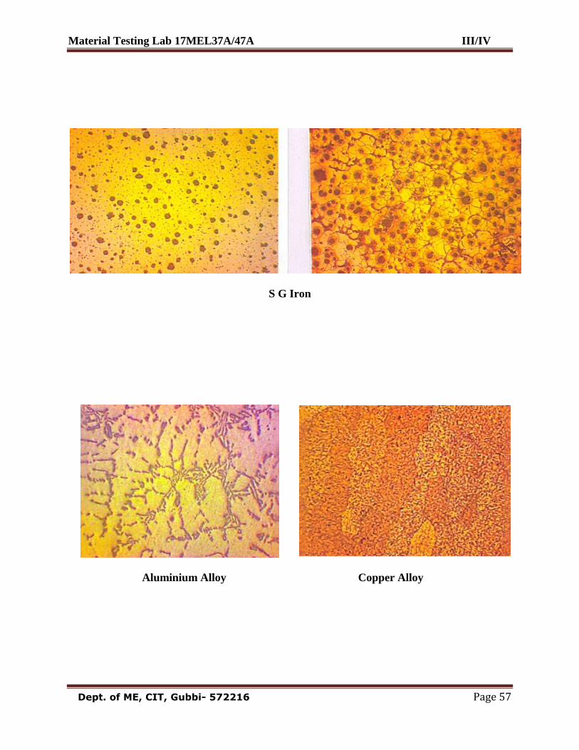
Metallurgical Microscope is by far the most important tool of the metallurgist from both
the scientific and technical stand point. It helps determining:
a) Grain size and shape.
b) Size, shape and distribution of various phases and inclusion.
c) Mechanical and thermal treatment of the alloys.
Preparation of Specimen:
Preparation of specimen is necessary to study its microstructure, because the
metallurgical microscope discussed earlier makes use of the principle of reflection of light from
the specimen to obtain the final image of the metal structure. Following are the steps involved in
the preparation of specimen:
1) Selection of specimen: When investigating the properties of a metal or alloy, it is essential
that the specimen should be selected from that area (of the alloy plate or casting) which can be
taken as representative of the whole mass.
2) Cutting of the specimen: After selecting a particular area in the whole mass, the specimen
may be removed with the help of appropriate cutting tools.
3) Mounting the specimen: If the specimen is too small to be held in hand for further
processing, it should be mounted on a thermoplastic resin disc or some other low melting point
alloy.
4) Obtaining flat specimen surface: It is first necessary to obtain a reasonably flat surface on
the specimen. This is achieved by using a fairly coarse file or machining or grinding.
5) Intermediate and Fine Grinding: Intermediate and fine grinding is carried out using emery
papers of progressively finer grade.
Material Testing Lab 17MEL37A/47A III/IV
Dept. of ME, CIT, Gubbi- 572216 Page 57
S G Iron
Aluminium Alloy Copper Alloy
Material Testing Lab 17MEL37A/47A III/IV
Dept. of ME, CIT, Gubbi- 572216 Page 58
6) Rough polishing: A very small quantity of diamond powder (particle size about 6 microns)
carried in a paste that is oil-soluble is placed on the nylon cloth-covered surface of a rotating
polishing wheel. The specimen is pressed against the cloth of the rotating wheel with
considerable pressure and is moved around the wheel in the direction opposite to rotation of the
wheel to ensure a more uniform action.
7) Fine polishing: The polishing compound used is alumina (Al2O3) powder placed on a cloth
covered rotating wheel. Distilled water is used as a lubricant. Fine polishing removes fine
scratches and very thin distorted layer remaining from the rough polishing stage.
8) Etching: Even after fine polishing, the granular structure in a specimen usually cannot be seen
under the microscope; because grain boundaries in a metal have a thickness of the order of a few
atom diameters at best, and the resolving power of a microscope is much too low to reveal their
presence.
In order to make the grain boundaries visible, after polishing the metal specimens are
usually etched. Etching imparts unlike appearances to the metal constituents and thus makes
metal structure apparent under the microscope.
Method- Before etching, the polished specimen is thoroughly washed in running water. Then,
the etching is done either by,
(i) Immersing the polished surface of the specimen in the etching reagent or by
(ii) Rubbing the polished surface gently with a cotton swab wetted with the
etching reagent.
After etching, the specimen is again washed thoroughly and dried. Now, the specimen
can be studied under the microscope.

Material Testing Lab 17MEL37A/47A III/IV
Dept. of ME, CIT, Gubbi- 572216 Page 59
Material Testing Lab 17MEL37A/47A III/IV
Dept. of ME, CIT, Gubbi- 572216 Page 60
Experiment 14: Date: __ /__ / _____
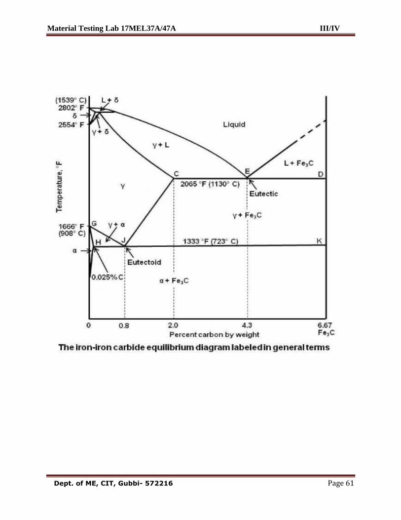
HEAT TREATMENT PROCESSES
In general, heat treatment can be defined as an operation, or the combination of
operations that involve heating and cooling of a metal in solid phase to obtain certain required
properties.
The ferrous materials can be heated to above transformation temperature and can be heat
– treated to obtain different structure.
The different heat treatment processes are based on heating the material to certain
temperature and employing different cooling rates.
In this process, heating temperature and rate of cooling adopted plays an important role.
The different processes are:
Annealing
Stress-relief annealing.
Process annealing.
Spheroidising.
Full annealing.
Normalizing
Hardening
Tempering
Annealing:
Annealing primarily is the process of heating a metal which is in a metastable or distorted
structural state, to a temperature which will remove the instability or distortion and then cooling
it to the room temperature so that the structure is stable and/or strain free.
Purpose of Annealing:
1. Removal of residual stress.
2. Refining and homogenizing the structure and to give a coarse pearlite structure.
3. Improving machinability.
4. Improving cold working characteristics for facilitating further cold work.
5. Producing desired microstructure.
6. Removing residual stresses.
7. Improving mechanical, physical, electrical and magnetic properties.
8. Reducing hardness.
Material Testing Lab 17MEL37A/47A III/IV
Dept. of ME, CIT, Gubbi- 572216 Page 61
Material Testing Lab 17MEL37A/47A III/IV
Dept. of ME, CIT, Gubbi- 572216 Page 62
Normalizing:
This process involves heating the metal above the transformation temperature up to 900º C
and cooling from that temperature adopting the required rate of cooling. This process involves:
Heating the metal to around 900º C so that the metal transforms completely into
austenite.
Holding at that temperature for some times (3minutes / mm of thickness)
Cooling at a rate of 80º C to 90
º C per hour up to 700
ºC
Then air – cooled from 700º C to room temperature.
Purpose of Normalizing:
Refining the grain structure and giving a fine pearlite structure.
Producing a uniform structure.
Achieving the required strength and ductility in a steel that is too soft and ductile for
machining.
Improving structures in welds.
In general, improving engineering properties of steels.
Hardening: (By Quenching)
Hardening is performed on metals to obtain desired hardness and structure. It involves:
Heating the metal above transformation temperature, around 900ºC
Holding at that temperature for 15 to 30 minutes per 25mm of cross-section.
Quenching it immediately in a suitable cold medium (brine solution,
Water, oil etc.)
Hardness obtained will depend upon the Composition of the material, nature and
properties of quenching medium and quenching temperature.
Properties obtained by hardening are:
Desired hardness can be obtained.
Strength of material is increased.
Wear resistance is increased.
Martensite structure is obtained.

Material Testing Lab 17MEL37A/47A III/IV
Dept. of ME, CIT, Gubbi- 572216 Page 63
Material Testing Lab 17MEL37A/47A III/IV
Dept. of ME, CIT, Gubbi- 572216 Page 64
Tempering:
Hardening of metal produces Martensite structure with some retained austenite. The
martensite structure makes the metal very hard and brittle. The retained austenite is unstable and
it will change with time. This transformation of retained austenite even at room temperature
leads to distortion of metal. Due to these factors the hardened metal cannot be used as it is.
Hence tempering is carried out on the metals.
Tempering treatment involves:
Heating the metal just above Martensite structure temperature (50 O
C),
Holding it at that temperature for some time and then cooling either rapidly or slowly. The
purpose of tempering is to remove brittleness and improve ductility in the material.
The Properties obtained after Tempering are:
Improvement in ductility and toughness.
Slight reduction in hardness.
Increase in tensile strength.
Reduction in internal stress.
Material Testing Lab 17MEL37A/47A III/IV
Dept. of ME, CIT, Gubbi- 572216 Page 65
TYPICAL VIVA QUESTION WITH ANSWERS
1) Homogeneity: Material should be of same type and uniformly distributed throughout the
body.
2) Orthotropic: Materials have different properties in different directions, e.g.orthotropic Plates.
3) Isotropy: Properties is same or identical at all points in the body of the material.
4) Anisotropy: Properties will not be identical at all points in the body of the material.
5) Elasticity: It is the property by which the deformations caused in a body by external force
disappears on removal of the forces. The resulting forces are within the elastic limit.
6) Plasticity: It is the property by which the deformation caused in a body by external forces
does not disappear on removal of forces. We say there is permanent set in material. In a tension
test, the material enters the plastic region after the elastic region is passed .
7) Ductility: Property by with the materials can be drawn into thin wires. The percentage
elongation or contraction gives a measure of Ductility. In this case, large deformations occur
before rupture.
8) Brittleness: If the Fracture in a material occurs when the stress exceeds the elastic limit.
Tendency to break under Impact loads. It is opposite to ductility.
9) Tenacity: The property of a material to resist tension or tensile stress is called Tenacity.
10) Malleability: It is the property by which the material can be beaten into sheets. E.g. Gold.
Gold is the most malleable metal.
11) Rigidity: Sometimes, some materials are rigid against shear deformation. i e. they resist the
deformations caused due to shear. Such property of the materials is termed as rigidity.
12) Toughness: The property of a material to-resist fracture under suddenly applied loads is
termed as Toughness. To some extent, toughness is related to impact resistance.
13) Modulus of Toughness: It is the work-done on the body in loading up to rupture point per
unit volume or it is the area enclosed between stress-strain diagram up to rupture point (see.
Graph 2)
14) Resilience: It is the work done on the body in loading it up to elastic limit per unit volume or
it is the strain energy stored at elastic limit per unit volume. It is given by the area of the stress-
strain diagram up to elastic limit (ref Graph 2). It is also termed as "Modulus of Resilience".
Modulus of resilience = shaded area in graph 2.
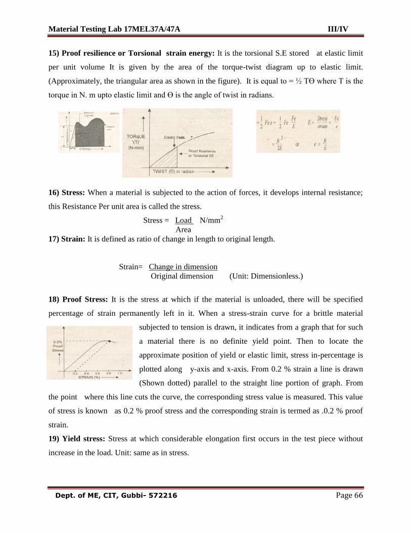
Material Testing Lab 17MEL37A/47A III/IV
Dept. of ME, CIT, Gubbi- 572216 Page 66
15) Proof resilience or Torsional strain energy: It is the torsional S.E stored at elastic limit
per unit volume It is given by the area of the torque-twist diagram up to elastic limit.
(Approximately, the triangular area as shown in the figure). It is equal to = ½ TӨ where T is the
torque in N. m upto elastic limit and Ө is the angle of twist in radians.
16) Stress: When a material is subjected to the action of forces, it develops internal resistance;
this Resistance Per unit area is called the stress.
Stress = Load N/mm2
Area
17) Strain: It is defined as ratio of change in length to original length.
Strain= Change in dimension
Original dimension (Unit: Dimensionless.)
18) Proof Stress: It is the stress at which if the material is unloaded, there will be specified
percentage of strain permanently left in it. When a stress-strain curve for a brittle material
subjected to tension is drawn, it indicates from a graph that for such
a material there is no definite yield point. Then to locate the
approximate position of yield or elastic limit, stress in-percentage is
plotted along y-axis and x-axis. From 0.2 % strain a line is drawn
(Shown dotted) parallel to the straight line portion of graph. From
the point where this line cuts the curve, the corresponding stress value is measured. This value
of stress is known as 0.2 % proof stress and the corresponding strain is termed as .0.2 % proof
strain.
19) Yield stress: Stress at which considerable elongation first occurs in the test piece without
increase in the load. Unit: same as in stress.
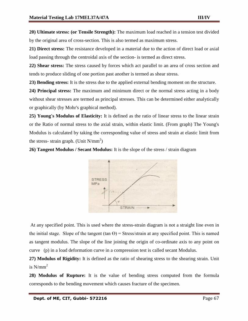
Material Testing Lab 17MEL37A/47A III/IV
Dept. of ME, CIT, Gubbi- 572216 Page 67
20) Ultimate stress: (or Tensile Strength): The maximum load reached in a tension test divided
by the original area of cross-section. This is also termed as maximum stress.
21) Direct stress: The resistance developed in a material due to the action of direct load or axial
load passing through the centroidal axis of the section- is termed as direct stress.
22) Shear stress: The stress caused by forces which act parallel to an area of cross section and
tends to produce sliding of one portion past another is termed as shear stress.
23) Bending stress: It is the stress due to the applied external bending moment on the structure.
24) Principal stress: The maximum and minimum direct or the normal stress acting in a body
without shear stresses are termed as principal stresses. This can be determined either analytically
or graphically (by Mohr's graphical method).
25) Young's Modulus of Elasticity: It is defined as the ratio of linear stress to the linear strain
or the Ratio of normal stress to the axial strain, within elastic limit. (From graph) The Young's
Modulus is calculated by taking the corresponding value of stress and strain at elastic limit from
the stress- strain graph. (Unit N/mm2)
26) Tangent Modulus / Secant Modulus: It is the slope of the stress / strain diagram
At any specified point. This is used where the stress-strain diagram is not a straight line even in
the initial stage. Slope of the tangent (tan Ө) = Stress/strain at any specified point. This is named
as tangent modulus. The slope of the line joining the origin of co-ordinate axis to any point on
curve (p) in a load deformation curve in a compression test is called secant Modulus.
27) Modulus of Rigidity: It is defined as the ratio of shearing stress to the shearing strain. Unit
is N/mm2
28) Modulus of Rupture: It is the value of bending stress computed from the formula
corresponds to the bending movement which causes fracture of the specimen.
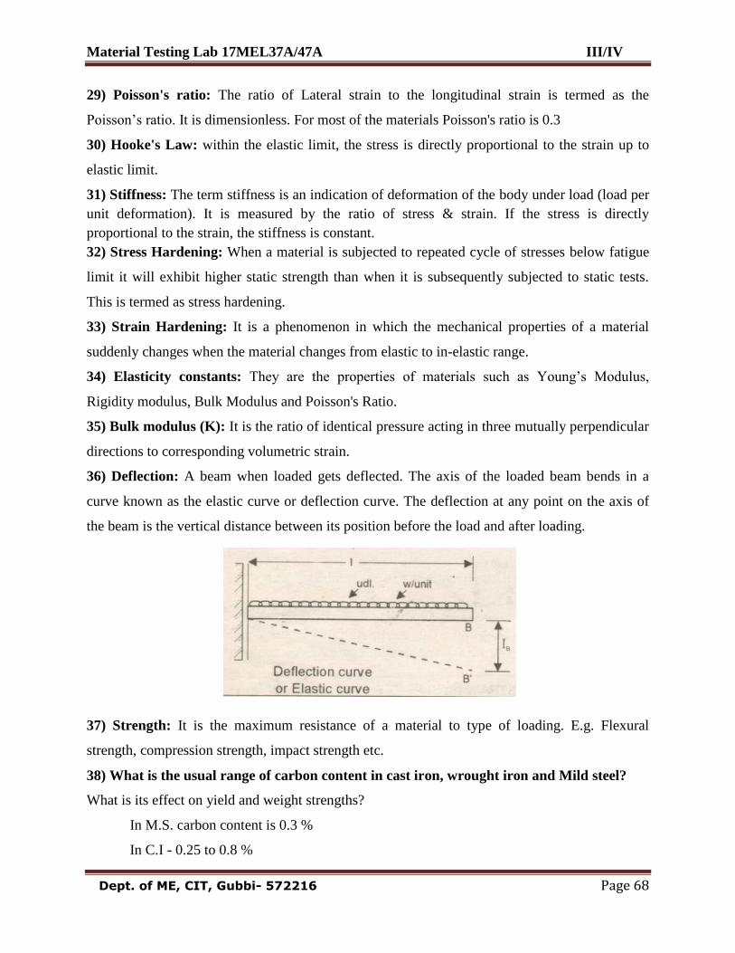
Material Testing Lab 17MEL37A/47A III/IV
Dept. of ME, CIT, Gubbi- 572216 Page 68
29) Poisson's ratio: The ratio of Lateral strain to the longitudinal strain is termed as the
Poisson‟s ratio. It is dimensionless. For most of the materials Poisson's ratio is 0.3
30) Hooke's Law: within the elastic limit, the stress is directly proportional to the strain up to
elastic limit.
31) Stiffness: The term stiffness is an indication of deformation of the body under load (load per
unit deformation). It is measured by the ratio of stress & strain. If the stress is directly
proportional to the strain, the stiffness is constant.
32) Stress Hardening: When a material is subjected to repeated cycle of stresses below fatigue
limit it will exhibit higher static strength than when it is subsequently subjected to static tests.
This is termed as stress hardening.
33) Strain Hardening: It is a phenomenon in which the mechanical properties of a material
suddenly changes when the material changes from elastic to in-elastic range.
34) Elasticity constants: They are the properties of materials such as Young‟s Modulus,
Rigidity modulus, Bulk Modulus and Poisson's Ratio.
35) Bulk modulus (K): It is the ratio of identical pressure acting in three mutually perpendicular
directions to corresponding volumetric strain.
36) Deflection: A beam when loaded gets deflected. The axis of the loaded beam bends in a
curve known as the elastic curve or deflection curve. The deflection at any point on the axis of
the beam is the vertical distance between its position before the load and after loading.
37) Strength: It is the maximum resistance of a material to type of loading. E.g. Flexural
strength, compression strength, impact strength etc.
38) What is the usual range of carbon content in cast iron, wrought iron and Mild steel?
What is its effect on yield and weight strengths?
In M.S. carbon content is 0.3 %
In C.I - 0.25 to 0.8 %
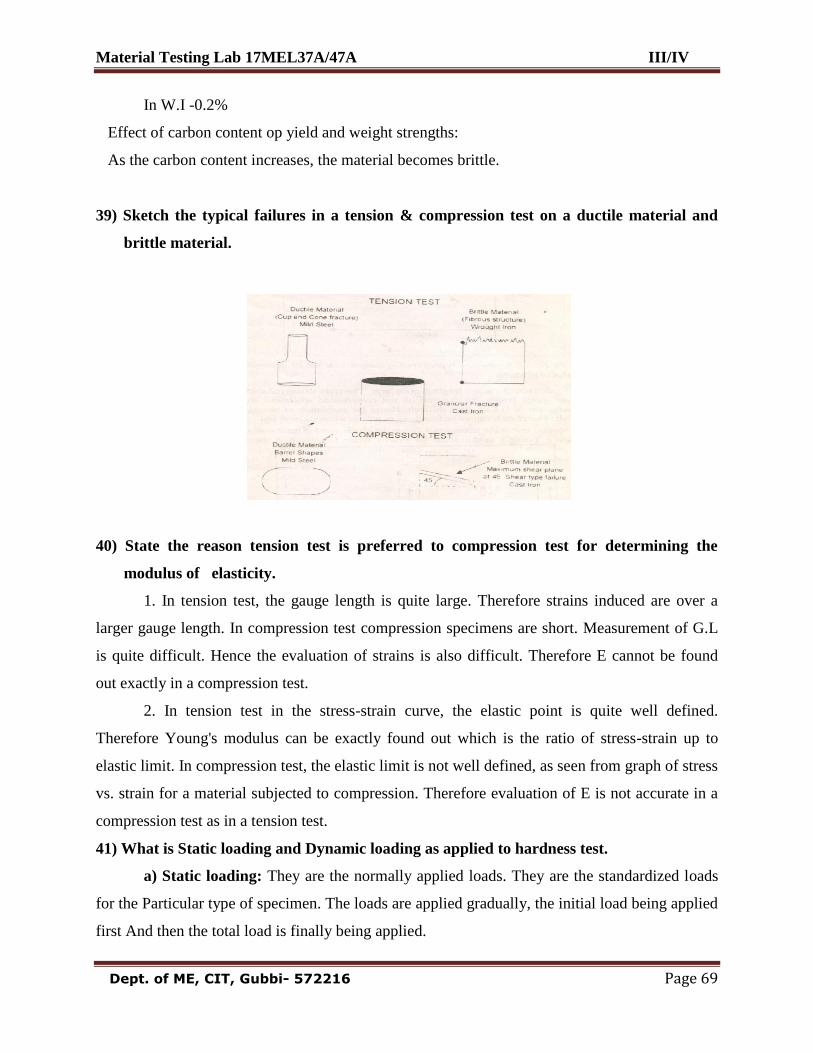
Material Testing Lab 17MEL37A/47A III/IV
Dept. of ME, CIT, Gubbi- 572216 Page 69
In W.I -0.2%
Effect of carbon content op yield and weight strengths:
As the carbon content increases, the material becomes brittle.
39) Sketch the typical failures in a tension & compression test on a ductile material and
brittle material.
40) State the reason tension test is preferred to compression test for determining the
modulus of elasticity.
1. In tension test, the gauge length is quite large. Therefore strains induced are over a
larger gauge length. In compression test compression specimens are short. Measurement of G.L
is quite difficult. Hence the evaluation of strains is also difficult. Therefore E cannot be found
out exactly in a compression test.
2. In tension test in the stress-strain curve, the elastic point is quite well defined.
Therefore Young's modulus can be exactly found out which is the ratio of stress-strain up to
elastic limit. In compression test, the elastic limit is not well defined, as seen from graph of stress
vs. strain for a material subjected to compression. Therefore evaluation of E is not accurate in a
compression test as in a tension test.
41) What is Static loading and Dynamic loading as applied to hardness test.
a) Static loading: They are the normally applied loads. They are the standardized loads
for the Particular type of specimen. The loads are applied gradually, the initial load being applied
first And then the total load is finally being applied.
Material Testing Lab 17MEL37A/47A III/IV
Dept. of ME, CIT, Gubbi- 572216 Page 70
b) Dynamic loading: Application of suddenly applied loads on the surface of specimen
to determine the hardness of metals is called dynamic loading.
42) Very hard materials cannot be tested in Brinell Hardness testing machine. State the
reason.
For very hard materials like case hardened steel, spring steel, etc., the indentation made on
the specimen in B.H. test is very small, because the standard ball diameter is small equal to
2.5mm and intensity of load applied is very small. As the B.H. number is a function of the
spherical area of indentation and load, if the indentation area is small, it greatly affects the
hardness value of the material. Hence, for very hard material B.H. test is not suitable.
43) What is the purpose of applying the minor load in case of Rockwell Hardness test?
We should have a datum load (or a reference load) before applying the major load on the
surface of specimen so that a proper and clear indentation is made on the surface of specimen.
The datum or the reference load that is applied on specimen is called the minor load which is
normally 10 Kg in Rockwell Hardness test. After the application of minor load the total major
load is applied on the specimen.
44) What physical property is determined from impact test? What is its significance?
The physical property determined from impact test is the resistance of a material due to
suddenly applied loads or prepared clutches. Ex. Helipad, i.e. a helicopter landing suddenly on
the Landing pad causing sudden impact, impact of a drop hammer, etc.,
45) What are the types of impact tests?
a) Izod impact test: Specimen is placed as a cantilever. The type of notch will be „V‟
type. The notch is facing the direction of striker of hammer.
b) Charpy Impact test: Specimen is placed as a simply supported beam. The type of
notch is „U‟ type. The notch will be facing on the opposite direction of striker of hammer.
46) What is meant by Notch Sensitivity? Or what is the effect of notching on test specimens.
In order to induce a fracture to occur in a ductile material under a single blow in a impact
test, the specimen is generally notched. The use of notch tends to reduce the ductility causing a
brittle type of fracture or the tendency of a ductile material to act like a brittle material, when
broken in the form of a notched specimen is called Notch Sensitivity.
Material Testing Lab 17MEL37A/47A III/IV
Dept. of ME, CIT, Gubbi- 572216 Page 71
VIVA QUESTIONS ON MT LAB
Tensile test:
1. Differentiate between Engineering Stress/Strain and True Stress/Strain.
2. What is meant by Plastic & Elastic Deformation?
3. Define Upper Yield Point; Lower Yield Point; Ultimate Strength; Fracture Strength.
4. What is meant by Gauge Length?
5. What are the various types of fractures?
6. Differentiate between Brittleness and ductility?
7. Define the term Malleability?
8. What is Strain hardening?
9. How the micro structural defect like slip effects the deformation?
Compressive strength test:
1. Differentiate between Compressive strength and tensile strength.
2. Describe the fracture mechanism of a material under compressive loading.
3. Theoretically compressive strength should be same as the tensile strength of a material,
but practically it is not. Why?
4. What is anisotropy? How does it effect the mechanical properties?
Modulus of rigidity:
1. What is meant by modulus of rigidity?
2. Define torsion strength.
3. What are the factors which may affect the angle of twist?
4. What will be the effect on strength if a solid circular shaft is replaced by a hallow shaft of
same dimension.
5. What is meant by strain energy? Give its expression in torsion for solid and hollow
circular shaft.
6. What is Poisson‟s Ratio?
Impact test:
1. What is meant by toughness?
2. What is the purpose of V-notch in impact testing and what is its dimension?
3. What is resilience?
4. How does tempering changes the toughness of a material?
5. Define Notch Impact Strength & Modulus of Rupture.
6. Differentiate between Izod & Charpy impact testing techniques?
Young’s modulus:
1. What is Young‟s Modulus?
Material Testing Lab 17MEL37A/47A III/IV
Dept. of ME, CIT, Gubbi- 572216 Page 72
2. What is meant by Moment of Inertia?
3. How to find out the least count of vernier caliper.
4. What is the effect of temperature on Young‟s Modulus?
5. How will you define a „beam‟?
6. What is the difference between a simple supported beam & cantilever beam?
7. What is the formula used to calculate the Moment of Inertia of a Square section beam;
Rectangular section beam and a circular beam about the axis.
8. What is meant by Polar Moment of Inertia & how is it calculated?
9. Derive the relationship between Young‟s Modulus, Modulus of Rigidity & Bulk
Modulus.
10. Describe different types of loads on beam with the help of sketches
Heat Treatment:
1. What is meant by heat treatment?
2. What are the different types of heat treatment?
3. Enumerate the need for heat treatment of steel?
4. List different types of hardness testing methods?
5. What is meant by BHN?
6. Differentiate between hardenability and hardness?
7. What are the different types of indenters used in hardness testing?
8. What are the factors which effect the hardness of steels?
9. Why is the minor load applied before applying the major load?
10. Derive the formula to calculate BHN.
Microstructures:
1. Why the microstructures of metals are different from each other?
2. What are the effects of microstructure of steel and CI on their mechanical properties?
3. In which way is the microstructure of copper different from the microstructure of brass?
4. Define Pearlite, Austenite, Ferrite, Cementite, Martensite, Bainite, and Ledeburite.
5. What is the purpose of alloying? Describe few alloys of Copper and Aluminium.
6. How are steels classified based on their alloying (carbon) content?
7. What is Cast Iron? What are its types?
8. What are stainless steels? Give its composition.
9. Discuss in brief, the steel manufacturing process.
10. Discuss the properties and manufacturing process of the following: Composites;
Ceramics; Plastics and Glass.
11. What are the specifications of grinding and polishing machines?
12. What is lapping? Which degree of accuracy can be achieved in metals by Polishing?
Material Testing Lab 17MEL37A/47A III/IV
Dept. of ME, CIT, Gubbi- 572216 Page 73
13. Why is grinding performed before polishing?
14. What is the need of polishing on four grades of emery paper?
15. Why is the specimen rotated by 90°, while changing from one grade of emery Paper to
another?
16. Why is dry polishing done before wet polishing?
17. What is the purpose of wet polishing after dry polishing?
18. Why is alumina powder used in wet polishing?
19. What is the purpose of etching?
20. Which etchant is used for etching MS; aluminum; copper?
21. What is the principle of working of metallurgical microscope?