department of mechanical engineering - … lab.docx · web viewdepatment of mechanical engineering...
TRANSCRIPT

SRI VENKATESWARA COLLEGE OF ENGINEERING AND TECH
(AUTONOMOUS)
RVS NAGAR, CHITTOOR-517127
DEPATMENT OF MECHANICAL ENGINEERING
I M.Tech II SemDOM (2015-16)
MACHINE DESIGNLABORATORY MANUAL
Prepared by
DEPATMENT OF MECHANICAL ENGINEERING
SRI VENKATESWARA COLLEGE OF ENGINEERING AND TECHNOLOGY
RVS NAGAR, CHITTOOR-51712
Department of Mechanical Engineering, SVCET, CHITTOOR

PORTER GOVERNORExperiment No.
Date:
AIM: To prepare the performance characteristic curves on porter governor
APPARATUS: Universal governor apparatus
EXPERIMENTAL PROCEDURE:
The porter Governor mechanism is fitted with chosen weights to the spindle shaft. Ensure that the
nut & bolts of all the moving parts and of the spindle shaft are properly tightened. Then following
simple procedure is to be followed.
1. Keep the knob of the dimmer-stat in zero position before switching on the main supply.
2. Switch on the main supply and gradually go on increasing the speed of the motor. Due to this the
center sleeve rises from the lower stop aligning with the marking on the scale. This is initial lift of
the sleeve.
3. Note down the readings of the sleeve position and speed for this initial lift. Speed of the motor is
to be measured by hand tachometer, from the counter hole provided on the spindle.
4. Then increase the speed in steps to give suitable sleeve movement and note down the readings of
sleeve displacement and the corresponding speed. All the readings are to be entered in a tabular
observation table.
5. After completing the experiment bring the knob of the dimmer-stat to its original position i.e.
zero slowly and gradually. Then switch off the main supply.
Dimensions
a) Length of each link - L = 0.125 m.
b) Initial height of Governor – ho = 0.105 m.
Department of Mechanical Engineering, SVCET, CHITTOOR

c) Initial radius of rotation – ro = 0.120 m.
d) Weight of each ball - W = 0.6 kg.
e) Weight of Sleeve weight = 0.5 kg.
Radius of rotation `r` at any position could be found as follows
a) Find height h = ho – X/2 m. ho = 0.10 m
b) Find “ “ by using = Cos –1 (h/L) in Degrees
c) Then r = 0.05 + L Sin m.
d) Angular Velocity ‘’ = 2N/60 rad/s
OBSERVATION TABLE
Sl. No. Speed
N rpm
Sleeve Displacement
X in meter
Height
h in m
Radius of rotation
r in m
Force
F = m 2 r
in N
Following graphs to be plotted:
a) Force Vs Radius of rotation.
b) Speed Vs Sleeve Displacement.
PRECAUTIONS:
Department of Mechanical Engineering, SVCET, CHITTOOR
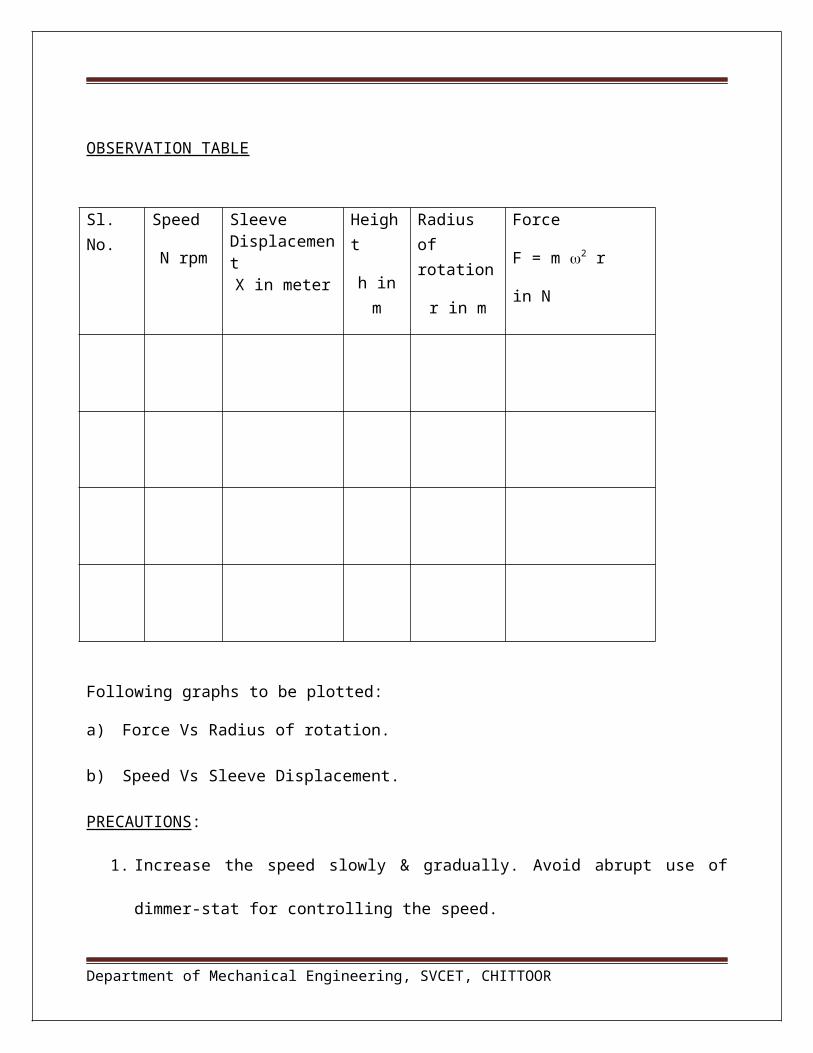
1. Increase the speed slowly & gradually. Avoid abrupt use of dimmer-stat for controlling the
speed.
2. Take the sleeve displacement reading when the pointer is steady.
3. See that at higher speed the load on sleeve does not hit the upper sleeve of the Governor.
4. While closing the test bring the dimmer to zero position and then switch OFF the motor.
RESULT
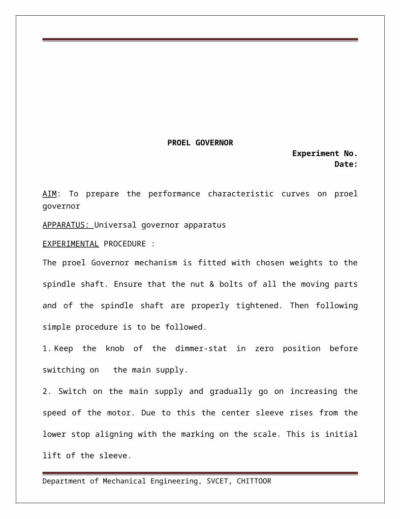
PROEL GOVERNOR
Department of Mechanical Engineering, SVCET, CHITTOOR

Experiment No. Date:
AIM: To prepare the performance characteristic curves on proel governor
APPARATUS: Universal governor apparatus
EXPERIMENTAL PROCEDURE :
The proel Governor mechanism is fitted with chosen weights to the spindle shaft. Ensure that the
nut & bolts of all the moving parts and of the spindle shaft are properly tightened. Then following
simple procedure is to be followed.
1. Keep the knob of the dimmer-stat in zero position before switching on the main supply.
2. Switch on the main supply and gradually go on increasing the speed of the motor. Due to this the
center sleeve rises from the lower stop aligning with the marking on the scale. This is initial lift of
the sleeve.
3. Note down the readings of the sleeve position and speed for this initial lift. Speed of the motor is
to be measured by hand tachometer, from the counter hole provided on the spindle.
4. Then increase the speed in steps to give suitable sleeve movement and note down the readings of
sleeve displacement and the corresponding speed. All the readings are to be entered in a tabular
observation table.
5. After completing the experiment bring the knob of the dimmerstat to its original position i.e.
zero slowly and gradually. Then switch off the main supply.
Dimensions
a) Length of each link - L = 0.125 m.
b) Initial height of Governor – ho = 0.100 m.
Department of Mechanical Engineering, SVCET, CHITTOOR
c) Initial radius of rotation – ro = 0.127 m.
d) Mass of ball - m = 0.6 kg.
e) Extension of length BG = 0.075 m.
Go on increasing the speed gradually and take the readings of speed of rotation ‘N’ and corresponding sleeve displacement ‘X’. Complete the following observation table.
Sl. No. Speed
N rpm
Sleeve Displacement
X in meter
Radius of rotation
r in m
Force
F = m 2 r
in N
a) Find height h = ho – ( x/2 )
b) Find r in static condition for different sleeve displacementc) Angular Velocity ‘’ = 2N/60 rad/sec
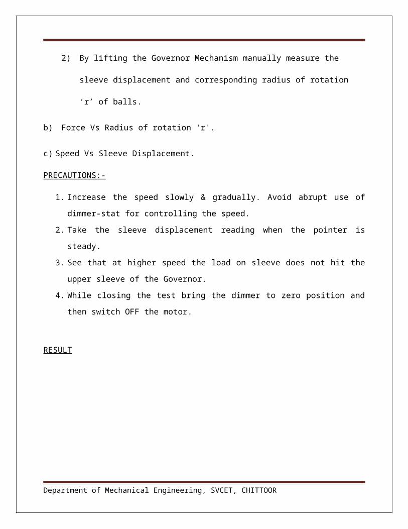
Following graphs to be plotted:
a) Sleeve Disp. 'X' Vs 'r' Radius of rotation.
To draw this graph proceeds as follows:
1) Keep the Governor in static position.
2) By lifting the Governor Mechanism manually measure the sleeve displacement and
corresponding radius of rotation ‘r’ of balls.
Department of Mechanical Engineering, SVCET, CHITTOOR

b) Force Vs Radius of rotation 'r'.
c) Speed Vs Sleeve Displacement.
PRECAUTIONS:-
1. Increase the speed slowly & gradually. Avoid abrupt use of dimmer-stat for controlling the
speed.
2. Take the sleeve displacement reading when the pointer is steady.
3. See that at higher speed the load on sleeve does not hit the upper sleeve of the Governor.
4. While closing the test bring the dimmer to zero position and then switch OFF the motor.
RESULT
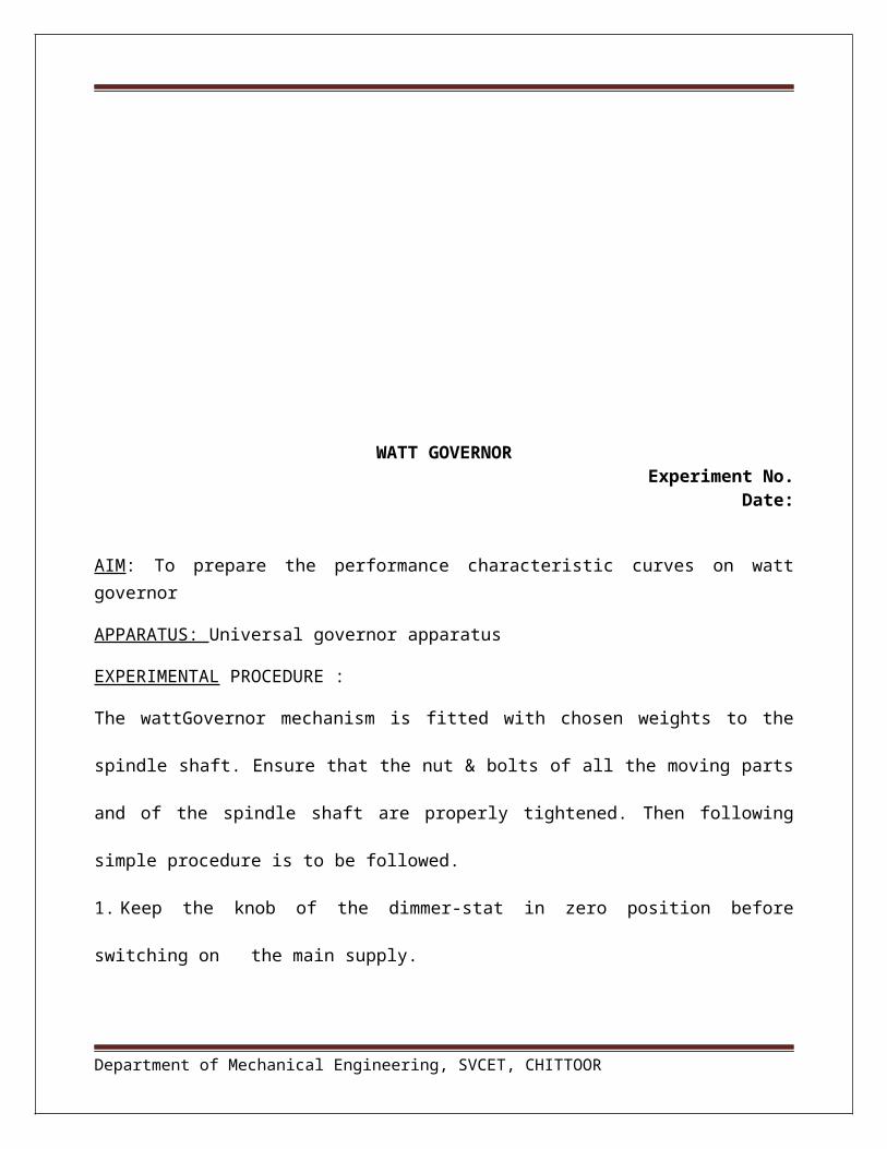
WATT GOVERNOR Experiment No.
Date:
Department of Mechanical Engineering, SVCET, CHITTOOR
B

AIM: To prepare the performance characteristic curves on watt governor
APPARATUS: Universal governor apparatus
EXPERIMENTAL PROCEDURE :
The wattGovernor mechanism is fitted with chosen weights to the spindle shaft. Ensure that the nut
& bolts of all the moving parts and of the spindle shaft are properly tightened. Then following
simple procedure is to be followed.
1. Keep the knob of the dimmer-stat in zero position before switching on the main supply.
2. Switch on the main supply and gradually go on increasing the speed of the motor. Due to this the
center sleeve rises from the lower stop aligning with the marking on the scale. This is initial lift of
the sleeve.
3. Note down the readings of the sleeve position and speed for this initial lift. Speed of the motor is
to be measured by hand tachometer, from the counter hole provided on the spindle.
4. Then increase the speed in steps to give suitable sleeve movement and note down the readings of
sleeve displacement and the corresponding speed. All the readings are to be entered in a tabular
observation table.
5. After completing the experiment bring the knob of the dimmerstat to its original position i.e.
zero slowly and gradually. Then switch off the main supply.
Dimensions
a) Length of each link - L = 0.125 m.
b) Initial height of Governor – ho = 0.100 m.
c) Initial radius of rotation – ro = 0.127 m.
d) Mass of ball - m = 0.6 kg.
Department of Mechanical Engineering, SVCET, CHITTOOR
e) Extension of length BG = 0.075 m.
Go on increasing the speed gradually and take the readings of speed of rotation ‘N’ and corresponding sleeve displacement ‘X’. Complete the following observation table.
Sl. No. Speed
N rpm
Sleeve Displacement
X in meter
Radius of rotation
r in m
Force
F = m 2 r
in N
a) Find height h = ho – ( x/2 )
b) Find r in static condition for different sleeve displacementc) Angular Velocity ‘’ = 2N/60 rad/sec
Following graphs to be plotted:
a) Sleeve Disp. 'X' Vs 'r' Radius of rotation.
To draw this graph proceeds as follows:
1) Keep the Governor in static position.
2) By lifting the Governor Mechanism manually measure the sleeve displacement and
corresponding radius of rotation ‘r’ of balls.
b) Force Vs Radius of rotation 'r'.
c) Speed Vs Sleeve Displacement.
Department of Mechanical Engineering, SVCET, CHITTOOR
PRECAUTIONS:-
1. Increase the speed slowly & gradually. Avoid abrupt use of dimmer-stat for controlling the
speed.
2. Take the sleeve displacement reading when the pointer is steady.
3. See that at higher speed the load on sleeve does not hit the upper sleeve of the Governor.
4. While closing the test bring the dimmer to zero position and then switch OFF the motor.
RESULT
MOTORISED GYROSCOPEExperiment No.
Date:
AIM: To find the gyroscopic couple acting on a rotating disc
Department of Mechanical Engineering, SVCET, CHITTOOR
B
ro

Apparatus: MOTORISED GYROSCOPEProcedure:
DESCRIPTION AND WORKING INSTRUCTIONS
The motor is coupled to the disc rotor, which is balanced. The disc shaft rotates about ‘X-X’ axis in
two-ball bearing housed in the frame No.1. This frame can swing about ‘Y-Y’ axis in bearings
provided in the yoke type frame No.2. While in a steady position, Frame No.1 is balanced. The yoke
frame is free to rotate about vertical axis ‘Z-Z’. Thus freedom of rotation about three perpendicular axis
is given to the rotor.
TECHNICAL DATA
1) Mass of Rotor (m) : 5.3 Kg.
2) Rotor Diameter (D) : 285 mm
3) Rotor Thickness : 10mm
Department of Mechanical Engineering, SVCET, CHITTOOR

4) Moment of inertia of the : m x D2/8
disc, coupling and motor : 0.538 kg.cm.sec2
rotor about central axis (I)
5) Distance of bolt of : 20.1cm.
weight pan from disc
center (L)
6) Motor : AC/DC, Fractional HP, Single Phase, 6000 rpm.
RULE NO.1
“The spinning body exerts a torque or couple in such a direction which tends to make the axis of
spin coincides with that of the precession.”
To study the rule of gyroscopic behavior following procedure may be adopted.
a) Balance the initial horizontal position of the rotor.
b) Start the motor by increasing the voltage with the dimmer, and wait until it attains constant speed.
c) Process the yoke frame No.2 about vertical axis by applying necessary force by hand to the same
( in the clockwise sense seen from above).
d) It will be observed that the rotor frame swings about the horizontal axis ‘YY’. Motor side is seen
coming upward and the weight pan side going downwards.
e) Rotate the vertical yoke axis in the anti-clockwise direction seen from above and observe that the
rotor frame swing in opposite sense (as compared to that in previous case following the above rule).
Department of Mechanical Engineering, SVCET, CHITTOOR

RULE NO.2
“The spinning body precise in such a way as to make the axis of spin coincide with that of the couple
applied, through 90o turn axis.”
a) Balance the rotor position on the horizontal frame.
b)Start the motor by increasing the voltage with the dimmer and wait till the disc attains constant speed.
c) Put weight ( 0.5 kg, 1 Kg. or 1.5 Kg.) in the weight pan, and start the stop watch to note the time in
seconds required for precession, through 30o or 90o etc.
d) The vertical yoke precise about OZ axis as per the rule No.2.
e) Speed may be measured by the tachometer
f) Enter the observation in the table.
OBSERVATION TABLE
Sr.No.
Speed N (RPM)
Load (w ) Kgs
Time (dt) sec
Degrees(d
p(rad/sec)
Tact
(Kg.cm)Tth
(Kg.cm)
Department of Mechanical Engineering, SVCET, CHITTOOR

GYROSCOPIC RELATION
Tactual = I x x p, where (Kg.cm) Tact = Gyroscopic Couple
I = M.I. of disc Kg.cm.sec.2
= Angular velocity of precession of disc in radians per second
=2 x π x N
=π x N
rad/sec60 30
Where N = RPM of disc
p = Angular velocity of precession of yoke about vertical axis - radians per second.
=d
xπ
rad/sec.dt 180
From above find
Tactual = I . . p Kg.cm
L = Distance of weight
Tth = w.L (Kg.cm.) w = weight applied in kgs.
=
p is to be calculated for short duration of time, as the balance of rotation of disc about the
horizontal axis YY is due to application of torque, and because of which p goes on reducing
gradually.
Department of Mechanical Engineering, SVCET, CHITTOOR

PRECAUTIONS
1.While measuring the speed with tachometer do not exert pressure on rotor shaft. Use of Non-
contact type tachometer or stroboscope for measurement of motor speed will give better results.
2.When the speed of rotor spin is changed, it takes some time to attain the constant speed due to
rotor inertia. Hence, it is advised to wait until the rotor spin reaches constant speed.
RESULT:
Department of Mechanical Engineering, SVCET, CHITTOOR

COMPOUND PENDULUM
Experiment No. Date:
AIM :
1. To determine the radius of gyration ‘k’ of given compound pendulum.
2. To verify the relation T = 2K2 + (OG)2
g (OG)
Where, T = Periodic time in sec.
K = Radius of gyration about C.G. ... cm.
OG= Distance of the C.G. of rod from support.
L = Free Length of suspended pendulum - cm.
g = 981 cm/sec2
DESCRIPTION
The compound pendulum consists of steel bar. The bar is supported in the hole by the knife edge.
PROCEDURE
1. Support the rod on knife edge.
2. Note the length of suspended pendulum and determine OG..
3. Allow the bar to oscillate and determine T by knowing the time for say 10 oscillations.
4. Complete the observation table given below.
Department of Mechanical Engineering, SVCET, CHITTOOR

OBSERVATION TABLE.
Sr.
No.
L
CmsOG
No. of
Oscn
Time for
‘n’ Osc.
Secs.
T sec
(Expt)
t/n
K
Expt.
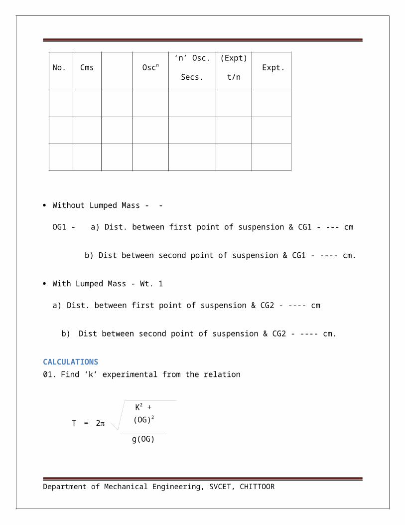
Without Lumped Mass - -
OG1 - a) Dist. between first point of suspension & CG1 - --- cm
b) Dist between second point of suspension & CG1 - ---- cm.
With Lumped Mass - Wt. 1
a) Dist. between first point of suspension & CG2 - ---- cm
b) Dist between second point of suspension & CG2 - ---- cm.
CALCULATIONS01. Find ‘k’ experimental from the relation
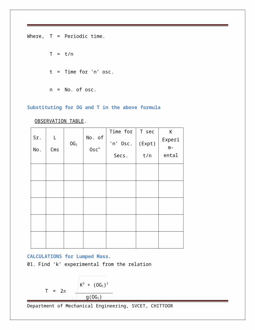
Where, T = Periodic time.
Department of Mechanical Engineering, SVCET, CHITTOOR
T = 2K2 + (OG)2
g(OG)

T = t/n
t = Time for ‘n’ osc.
n = No. of osc.
Substituting for OG and T in the above formula
OBSERVATION TABLE.
Sr.
No.
L
CmsOG1
No. of
Oscn
Time for
‘n’ Osc.
Secs.
T sec
(Expt)
t/n
K Experim-
ental
CALCULATIONS for Lumped Mass.01. Find ‘k’ experimental from the relation
Where, T = Periodic time.
K theo = L / 23
Department of Mechanical Engineering, SVCET, CHITTOOR
T = 2K2 + (OG1)2
g(OG1)

TRI-FILAR SUSPENSION(For Determination of Moment of Inertia)
Experiment No. Date:
AIM :
To determine the moment of Inertia of given specimen by using Tri-Filar suspension..
DESCRIPTION
A uniform circular disc is suspended from the pendulum support frame by three parallel cords. Top
ends of the cords are gripped by the drill chucks fixed links. The three links are joined to each other at
1200 angle and this assembly is fitted by stud to the top end of the frame.. It is possible to change the
length of the cord.
The suspension may also be used to determine the moment of Inertia of any body. In this case the body
under investigation is kept in the centre.
PROCEDURE
1. Suspend the disc by the hook. The suspension length of each cord must be the same. Keep any
one specimen on the bottom disc in the centre.
2.Allow the disc to oscillate about the vertical axis passing through the centre and measure the periodic time ‘t’ by knowing the time for say 10 oscillations.
3. Repeat the experiment by mounting the weights at equal distance from the centre.
4. Complete the observation table given below.
Department of Mechanical Engineering, SVCET, CHITTOOR
OBSERVATION TABLE.
Sr.
No.
L -
mtr.
a -
mtr.
No. of
Oscn
Time for
‘n’ Osc.
- ‘t’ Secs.
Periodic Time – T- ‘t/n’
MI of Disc
MI
of Ring.
Exp Theo. Exp. Theo.
CALCULATIONSFor Tri-Filar suspension
Mass Moment of Inertia of Disc - M.ITh. = Kg.m.s2
Where ‘W’ = Weight of Disc = _____ kgs.
‘D’ = Dia. of Disc = m
‘g’ = 9.81 m/s2
Mass Moment of Inertia of Ring = M.I.Th = ½ x W/g x (R12 + R2
2)
Where ‘W’ = Weight of Ring = ______ kgs.
‘R1’ = D/2 = ______/2 = ______ m : Outer Ring Radius.
‘R2’ = D/2 = ______/2 = ______m : Inner ring Radius.
Department of Mechanical Engineering, SVCET, CHITTOOR
W x D2
g x 8

Mass Moment of Inertia M.I.Exp. =
= = =
Where, ‘a’ = distance of wire from centre of Disc - m.
‘W’ = Weight of Disc or Ring.
‘T’ = Periodic Time = t/n
‘L’ = Length of Suspension.
RESULT:
Department of Mechanical Engineering, SVCET, CHITTOOR
W/g x g x a2 x T2 4 x 2 x L
W x a2 x T2
4 x 2 x L

STATIC & DYNAMIC BALANCING MACHINE
Experiment No. Date:
Aim: To study the dynamic balancing of rotating masses.
Apparatus: Dynamic balancing machine, weights, tachometer
Procedure:
1. Select weights for balancing.
2. Take a specimen weight which is having maximum weight in horizontal position i.e. in second position from reference weight say weight no.2.
3. Assume distance between 4 weights as shown in figure below
5 1 2 3
3cm 3cm 3cm
4. Now with reference to weight no.1 as ref. plane prepare following table
Wt. No. Spe. Weights in ‘gms’
Distance from Wt.No.4
Couple Angular Position
5 224 0 0 1920
1 232 3 696 00
2 230 6 1380 230
3 226 9 2034 1950
5. Now draw couple polygon with Weight No.2 in horizontal position.
a) Draw horizontal line of scale (Wt.No.2).
Department of Mechanical Engineering, SVCET, CHITTOOR
b) Take (Wt. No. ) distance in compass and draw an arc.
c) Take (Wt. No. ) distance in compass and draw an arc from another end.
d) Connect horizontal line with intersection point to form a triangle.
e) Measure the external angle as shown in figure.
6. Now draw force polygon as follows :
a) Draw a horizontal line C1 scale at 232 (Actual weight).
b) Draw a parallel line to C2 scale at 230.
c) Draw a parallel line to C3 scale at 226.
d) Join the line to form a polygon as shown in figure.
Department of Mechanical Engineering, SVCET, CHITTOOR
F1(232) )
F5 (222 )
F 3(226)
F 2 (230)
C2
C1
C3
230 1950
Couple Polygon 1
192 0
Force Polygon 2
7. As per the angles obtained from Force and Couple Polygons fix the weights accordingly in the main shaft.
8. Suspend total main frame by chains.
9. Attach belt to main frame and shaft the motor at low speed and observe vibrations on the frame. It is necessary to suspend the machine before the experiments. Using the values of ‘Wr’ obtained as above, and if the angular positions and planes of rotation of three of four blocks are known, the student can calculate the positions of other blocks for balancing of the complete system. From the calculations, the student finally clamps all the blocks on the shaft in there appropriate positions. Replace the motor belt; transfer the main frame to its hanging position and then by running the motor, one can verify that these calculations are correct and the blocks are perfectly balanced.
Precautions:
1. Before starting the experiment see that dimmer-stat at zero position.
2. Increase the speed slowly & gradually. Avoid abrupt use of dimmer-stat.
RESULT:
Department of Mechanical Engineering, SVCET, CHITTOOR
ROPE BRAKE DYNAMOMETER EXPERIMENTAL SET-UP
Experiment No. Date:
Aim : To determine the Force, Torque & Power of a Rope Brake Dynamometer.
Introduction : Dynamometer is a device for determining the Force, Torque and Power. It is simple
to fabricate and inexpensive type dynamometer. It is extensively used for testing of I.C. Engines.
There are two types of Dynamometers as given below.
a) Absorption Type :
i) Mechanical Type :
a) Prony Brake Type.
b) Rope Brake Type.
c) Band Brake Type.
ii) Hydraulic Type.
b) Transmission type. :
i) Mechanical Type :
a) Belt Transmission Type
ii) Electrical Type.
Department of Mechanical Engineering, SVCET, CHITTOOR

Description :
This dynamometer is designed and developed for the students undergoing Engineering courses, with
a view to make them understand the design features, construction, calculation of power, torque etc.
It consists of a base frame fabricated of MS Angle. A PMDC Motor is fitted on this frame. A small
drum is coupled to the motor directly to which a rope is wound. Loading frame having loading
screw with two spring balances are provided to measure load applied on the drum. One end of the
spring is hooked to the rope on the drum. Voltmeter & Ammeter is used to measure the input power
of the motor. A variable closed type dimmerstat is used to vary the speed of the motor.
Scope of Supply :
01. Base frame made from MS angle.
02. PMDC Motor : 1500 rpm, 0.5HP, 180 VDC.
03. Rope brake Dynamometer assembly coupled to the Motor shaft.
04. Loading screw with spring balances for applying load on the drum.
05. Dimmerstat : Closed Type, 0 – 2 amps, 230VAC.
06. Digital Voltmeter & Ammeter for measuring power input of the motor.
Procedure to conduct the experiment.
01. Before starting the experiment please ensure that there is no load on the drum. The both the
spring balance position should be at zero.
02. Switch on the power supply.
Department of Mechanical Engineering, SVCET, CHITTOOR

03. Slowly go on increasing the motor speed say 300 rpm or 450rpm. Let it run for few minutes as
there should be a constant speed. Speed can be measured by a Tachometer (Not in Scope of supply
).
04. Apply some load on the drum with the help of loading screw, be 0.25 kg or 0.4 kg
on the spring balance ( difference of the spring balance ).
05. Note down this load – S1& S2, speed in the observation table. For this load, measure
the V & I readings and fill the observation table.
06. Apply some more load on the drum with the help of loading screw. Ensure that
the load is not much on the motor, as it will stop. After completing the
experiment for the particular load and speed, unload the motor and bring the dimmer
position to zero position.
06. Repeat the above procedure for different loads and speeds.
07. The motor should be switched off only after the dimmer knob is brought to zero
position.
Observation Table.
Sr. No Speed Load on the Drum in N. Voltmeter Ammeter Torque
‘rpm’ S1
Kg.
S2
Kg.
Net
Load
‘W’ x
9.81..
‘N’
‘Volts’ ‘amps’ ‘Nm’
Department of Mechanical Engineering, SVCET, CHITTOOR

2 x x N x T
60
‘N’ S1 - S2 ‘V’ ‘I’ ‘T’
Calculations :
Constants / Data :
01. Drum Radius ‘R1’ : 150 mm.
02. Rope Diameter ‘D’ : 6 mm.
03. Speed ‘N’ : rpm.
Input Power ‘IP’ = V x I watts
Let ‘W’ = Net Load applied on the drum
= ( S1 - S2 ) x 9.81 ..... N
‘R’ = Effective Brake Drum Radius
= R1 + R2 ... mtr. = 0.075 + 0.006 = 0.081mtr.
Torque ‘T’ = W x R .. Nm
Now, Output Power ‘OP’ = …. Watt.
OP = …….. Watt.
Precaution :
Department of Mechanical Engineering, SVCET, CHITTOOR

01. Apply load on the drum gradually. Do not exceed load above _______Kgs.
02. Ensure ‘Zero’ position of the dimmer before starting the experiment.
03. Before stopping the unit, unload the applied load on the drum and bring
dimmer knob to zero position.
RESULT:
Department of Mechanical Engineering, SVCET, CHITTOOR