department of mechanical engineering m.tech...
TRANSCRIPT
9
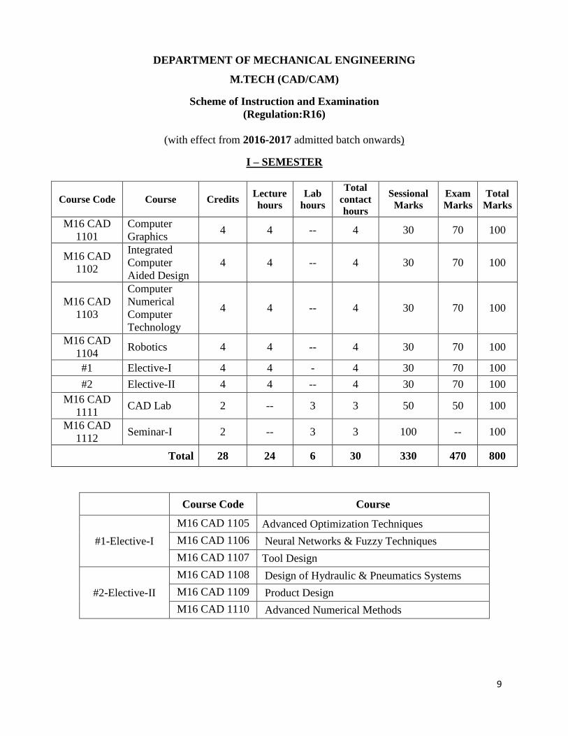
DEPARTMENT OF MECHANICAL ENGINEERING
M.TECH (CAD/CAM)
Scheme of Instruction and Examination
(Regulation:R16)
(with effect from 2016-2017 admitted batch onwards)
I – SEMESTER
Course Code Course Credits Lecture
hours
Lab
hours
Total
contact
hours
Sessional
Marks
Exam
Marks
Total
Marks
M16 CAD
1101
Computer
Graphics 4 4 -- 4 30 70 100
M16 CAD
1102
Integrated
Computer
Aided Design
4 4 -- 4 30 70 100
M16 CAD
1103
Computer
Numerical
Computer
Technology
4 4 -- 4 30 70 100
M16 CAD
1104 Robotics 4 4 -- 4 30 70 100
#1 Elective-I 4 4 - 4 30 70 100
#2 Elective-II 4 4 -- 4 30 70 100
M16 CAD
1111 CAD Lab 2 -- 3 3 50 50 100
M16 CAD
1112 Seminar-I 2 -- 3 3 100 -- 100
Total 28 24 6 30 330 470 800
Course Code Course
#1-Elective-I
M16 CAD 1105 Advanced Optimization Techniques
M16 CAD 1106 Neural Networks & Fuzzy Techniques
M16 CAD 1107 Tool Design
#2-Elective-II
M16 CAD 1108 Design of Hydraulic & Pneumatics Systems
M16 CAD 1109 Product Design
M16 CAD 1110 Advanced Numerical Methods

10
Code: M16 CAD 1101
COMPUTER GRAPHICS Theory : 4 Periods Sessionals : 30
Exam : 3 Hrs. Ext. Marks: 70
Credits : 4
COURSE OBJECTIVES:
1. This course is designed to provide a comprehensive introduction to computer graphics
leading to the ability to understand contemporary terminology, progress, issues, and trends.
2. A thorough introduction to computer graphics techniques, focusing on geometric
transformations, geometric algorithms, 3D object models (surface, volume and implicit),
visible surface algorithms, Shading and curve generation.
3. The interdisciplinary nature of computer graphics is emphasized in the wide variety of
examples and applications.
COURSE OUTCOMES
Upon completion of the subject, students will be able to
1. Understand the contemporary graphics hardware and terminology.
2. Implement graphics primitives, geometrical transformations and visibility detection.
3. Design and implement an application which illustrates the use of output primitives and 3D
viewing model.
4. Implement a method for the computer representation of objects.
SYLLABUS
Geometry and line generation: Line segments, Pixels and frame buffers, Bresenham's
algorithms: line, circle, ellipse generation. Graphics primitives: Primitive operations, The display-file interpreter, Display-file structure,
Display-file algorithms. Polygons: Polygons representation, An inside test, Filling polygons, Filling with a pattern.
Transformations: Scaling transformations, Reflection and zooming, Rotation, Homogeneous
coordinates and translation, Rotation about an arbitrary point. Segments: The segment table, Segment creation, Closing a segment, Deleting a segment.
Windowing and clipping: The viewing transformation, Clipping, The clipping of polygons,
Generalized clipping. Three dimensions: 3D geometry, 3D primitives, 3D transformations, Parallel projection,
Perspective projection, Isometric projections, Viewing parameters, Special projections. Hidden surfaces and lines: Back-face removal, Back -face algorithms, The Painter's algorithm,
Warnock's algorithm, Franklin algorithm, Hidden-line methods.
11
Light, color and shading: Point-source illumination, Shading algorithms, Shadows, Color
models. Curves and fractals: Curve generation, Interpolation, B splines, Curved surface patches, Bezier
curves, Fractals, Fractal lines, Fractal surfaces.
TEXT BOOK:
1. Computer Graphics - A Programming Approach by Steven Harrington, McGraw-Hill
International Edition, 1987.
REFERENCE BOOKS:
1. Schaum's Outline of Theory and Problems of Computer Graphics by Roy A. Plastock and
Gordon Kalley, McGraw-Hill Companies, Inc., 1986.
2. Mathematical Elements for Computer Graphics by David F. Rogersadn Adams.

12
Code: M16 CAD 1102
INTEGRATED COMPUTER AIDED DESIGN
Theory : 4 Periods Sessionals : 30
Exam : 3 Hrs. Ext. Marks: 70
Credits : 4
COURSE OBJECTIVES:
1. To understand the basic parametric fundamentals that is used to create and manipulate
geometric models.
2. To learn about the concepts of Geometric modelling and to acquire knowledge for generating
high quality images.
3. To learn about different tolerance methods, mass property calculations and animation
techniques used in designing.
COURSE OUTCOMES:
At the end of the course, the student shall be able to:
1. Understand geometric transformation techniques in CAD.
2. Develop mathematical models to represent lines, curves and surfaces used for engineering
applications.
3. Model engineering components using solid modelling techniques.
4. Design and analysis of engineering components.
SYLLABUS
Fundamentals of CAD: Introduction, Design process, Application of computer for design,
creating the manufacturing database, Benefits of CAD, Design work station, CAD hardware. Geometric modeling: Geometric modeling techniques - Multiple view 2D input, Wire frame
geometry, Surface models, Geometric entities - Curves and Surfaces, Solid modelers, Feature
recognition. Computer aided drafting: AutoCAD tools, 3D model building using solid primitives and
boolean operations, 3D model building using extrusion, Editing tools, Multiple views:
Orthogonal, Isometric. Visual realism: Shading solids, Coloring, Color models, Using interface for shading and
coloring. Graphic aids: Geometric modifiers, Naming scheme, Layers, Grids, Groups, Dragging and
rubber banding.
Computer animation: Conventional animation, Computer animation - Entertainment animation,
Engineering animation, Animation types, Animation techniques. Mechanical assembly: Assembly modeling, Part modeling, Mating conditions, Generation of
assembling sequences, Precedence diagram, Liaison-sequence analysis.
13
Mechanical tolerancing: Tolerance concepts, Geometric tolerancing, Types of geometric
tolerances, Location tolerances, Drafting practices in dimensioning and tolerancing, Tolerance
analysis. Mass property calculations: Geometrical property formulation - Curve length, Cross-sectional
area, Surface area, Mass property formulation - Mass, Centroid, Moments of inertia, Property
mapping. Properties of composite objects.
TEXT BOOK:
1. CAD/CAM Theory and Practice by Ibrahim Zeid.
REFERENCE BOOKS:
1. CAD/CAM Principles and Applications by P.N. Rao, Tata McGraw Hill Publishing
Company Ltd.
2. CAD/CAM Computer Aided Design and Manufacturing by Mikell P. Groover and Emory W.
Zimmer, Jr.
3. Computer Integrated Design and Manufacturing by David D. Bedworth, Mark R. Henderson,
Philip M. Wolfe.
14
Code: M16 CAD 1103
COMPUTER NUMERICAL CONTROL TECHNOLOGY
Theory : 4 Periods Sessionals : 30
Exam : 3 Hrs. Ext. Marks: 70
Credits : 4
COURSE OBJECTIVES:
1. To understand the importance of NC and CNC technology in manufacturing industry.
2. To understand the application of CAD/CAM systems in generating Part Programmes, in
particular for complex models.
3. To understand and apply the use of various transducers, encoders and feedback devices.
4. Identify and select proper NC tooling’s.
COURSE OUTCOMES:
Students will be able to
1. Understand the principles of Numerical Control (NC) technology and describe the range of
machine tools to which it is applied.
2. Outline the various routs for part programming in NC and CNC.
3. Explain the application of CNC for Machining & Turning Centers
SYLLABUS
Introduction: NC, DNC, CNC, Programmed Automations, Machine control unit, Part program,
NC tooling. NC machine tools: Nomenclature of NC machine axes, Types of NC machine tools, Machining
centres, Automatic tool changes (ATC), Turning centres. Machine control unit & tooling: Functions of MCU, NC actuation systems, Part program to
command signal, MCU organization, Computerized numerical control, Transducers for NC
machine tools, Tooling for NC machining centres and NC turning machines, Tool presetting. Manual part programming: Part program instruction formats, Information codes: Preparatory
function, Miscellaneous functions, Tool code and tool length offset, Interpolations, Canned
cycles. Manual part programming for milling operations, Turning operations, Parametric
subroutines. Computer aided part programming: NC languages: APT, NELAPT, EXAPT, GNC, VNC,
Pre-processor, Post processor. APT programming: APT language structure, APT geometry: Definition of point, time, vector,
circle, plane, patterns and matrices. APT motion commands: setup commands, point-to-point
motion commands, continuous path motion commands. Post processor commands, complication
control commands. Macro subroutines. Part programming preparation for typical examples.
15
TEXT BOOK:
1. Numerical Control and Computer Aided Manufacturing by T.K. Kundra, P.N. Rao and N.K.
Tewari, Tata McGraw-Hill Company Limited, New Delhi.
REFERENCE BOOKS:
1. Numerical Control of Machine Tools by Yoram Koren and Joseph Ben-Uri, Khanna
Publishers, Delhi.
2. CAD/CAM Principles and Applications by P.N. Rao, Tata McGraw Hill Publishing
Company Ltd.
16
Code: M16 CAD 1104
ROBOTICS
Theory : 4 Periods Sessionals : 30
Exam : 3 Hrs. Ext. Marks: 70
Credits : 4
COURSE OBJECTIVES:
1. To familiarize the students with anatomy, kinematics, sensors and dynamics of a
programmable machine of a robot.
COURSE OUTCOMES:
Students will be able to
1. Distinguish between fixed automation and programmable automation.
2. Identify various components of robot.
3. Select appropriate type of actuator for a joint.
4. Illustrate robot applications in manufacturing.
5. Analyze kinematics of a robot.
6. Derive equations of motion of a manipulator for a particular application.
SYLLABUS
Introduction: Basic concepts-Robot anatomy-robot configurations-Basic Robot motions-Types
of drives-Applications-Material Handling-Processing-Assembly and Inspection -Safety
considerations
Transformations and Kinematics: Vector operations-Translational transformations and
Rotational transformations-Properties of transformation matrices-Homogeneous transformations
and Manipulator-Forward solution-Inverse solution.
Controls and End Effectors: Control system concepts-Analysis-control of joints-Adaptive and
optimal control-End effectors-Classification- Mechanical-Magnetic-Vacuum-Adhesive-Drive
systems-Force analysis and Gripper design.
Robot Programming Methods: Languages-Computer control and Robot Software-VAL system
and Language.
Sensory Devices: Non optical and optical position sensors-Velocity and Acceleration-Range-
Proximity touch-Slip-Force-Torque- Machine vision-Image components-Representation -
Hardware Picture coding-Object recognition and categorization-Software consideration
TEXT BOOK:
1. Fu K.S.,Gonzalez R.C.., Lee C.S.G., "Robotics control,sensing,vision,and Intelligence",
McGraw Hill Book Co.,,1987.

17
REFERENCE BOOKS:
1. Klafter R.D., Cmielewski T.A. and Negin M , "Robot Engineering An Intergrated approach",
Prentice Hall of India,New Delhi.2,1994.
2. Deb S.R., "Robotics Technology and Flexible Automation", Tata McGraw Hill Publishing
Co., Ltd.,1994.
3. Craig J.J., "Introduction to Robotics Mechanics and Control", Addison Wesley,1999 5.
Groover M.P., "Industrial robotics Technology,programming and applications", McGraw
Hill Book Co.,1995.
18
Code: M16 CAD 1105
ADVANCED OPTIMIZATION TECHNIQUES
Theory : 4 Periods Sessionals : 30
Exam : 3 Hrs. Ext. Marks: 70
Credits : 4
COURSE OBJECTIVES:
1. To understand the theory of optimization methods and algorithms developed for solving
various types of optimization problems.
2. To apply the mathematical results and numerical techniques of optimization theory to
concrete Engineering problems.
3. To develop and promote research interest in applying optimization techniques in problems of
Engineering and Technology.
COURSE OUTCOMES:
1. Have a basic understanding of conventional and unconventional optimization algorithms.
2. Formulate engineering design problems as mathematical optimization problems and solve
them by using suitable optimization technique(s).
3. Use mathematical software for the solution of engineering problems.
4. Several homework assignments delving on core concepts and reinforcing analytical skills
learned in class.
SYLLABUS
Introduction: Statement of an optimization problem, Engineering Applications, Classification
of optimization problems
Geometric programming (G.P): Solution of an unconstrained geometric programming,
differential calculus method and arithmetic method. Primal dual relationship and sufficiency
conditions. Solution of a constrained geometric programming problem (G.P.P). Complementary
geometric programming (C.G.P), Simple applications of G.P
Dynamic programming (D.P): Multistage decision processes. Concepts of sub optimization,
computational procedure in dynamic programming calculus method and tabular methods. Linear
programming as a case of D.P. Continuous D.P, simple applications of D.P
Integer programming (I.P): Graphical representation. Gomory's cutting plane method. Bala's
algorithm for zero-one programming problem. Branch-and-bound method.
Stochastic programming (S.P): Basics concepts of probability theory, stochastic linear
programming
Unconventional optimization techniques: Multi-objective optimization - Lexicographic
method, Goal programming method, Genetic algorithms, A.N.N, Simulated Annealing
TEXT BOOK:
1. Engineering Optimization - Theory and Practice by Rao, S.S., New Age International (P)
Ltd. Publishers.

19
REFERENCE BOOKS:
1. Operations Research- Principles and Practice, Ravindran, Phillips and Solberg, John Wiely.
2. Introduction to Operations Research, Hiller and Lieberman, Mc Graw Hill.
3. Goal Programming and Extensions by James P. Ignizio, Lexigton Books.
4. Genetic Algorithms - In Search, Optimization and Machine Learning by David E. Goldberg,
Addison-Wesley Longman (Singapore) Pvt. Ltd.

20
Code: M16 CAD 1106
NEURAL NETWORKS AND FUZZY TECHNIQUES
Theory : 4 Periods Sessionals : 30
Exam : 3 Hrs. Ext. Marks: 70
Credits : 4
COURSE OBJECTIVES:
1. To conceptualize the working of human brain using Artificial Neural Network.
2. To become familiar with neural networks that can learn from available examples and
generalize to form appropriate rules for inference systems.
3. To introduce the ideas of fuzzy sets, fuzzy logic and use of heuristics based on human
experience.
COURSE OUTCOMES:
Students will be able to
1. Analyze and appreciate the applications which can use Neural Network and fuzzy logic.
2. Identify and describe NNFL techniques and their roles in building intelligent machines.
3. Design inference systems for decision making in manufacturing industries.
4. Realize the difference between learning and programming and explore practical applications
of Neural networks (NN).
5. Demonstrate the use of Neuro-fuzzy network for various industry applications.
SYLLABUS
Neural networks and fuzzy systems: Neural and fuzzy machine intelligence, Fuzzy as
multivalence, The dynamical - Systems approach to machine intelligence, Intelligent behaviour
as adaptive model - Free estimation.
Neural dynamics-I: Activations and signals, Neurons as functions, Signal monotonicity,
Biological activations and signals, Neuron fields, Neuronal dynamical systems, Common signal
functions, Pulse-coded signal functions.
Neuronal dynamics -II: Activation models, Neuronal dynamical systems, Additive neuronal
dynamics, Additive neuronal feedback, Additive bivalent models, BAM connection matrices,
Additive dynamic and the noise - Saturation dilemma, General neuronal Activations: Cohen-
Grossberg and multiplicative models. Synaptic Dynamics I: Unsupervised learning, Learning as
encoding, change, and quantization, Four unsupervised learning laws, Probability spaces and
random processes, Stochastic unsupervised learning and stochastic equilibrium, Signal Hebbian
learning, Competitive learning, Differential Hebbian learning, Differential competitive leering.
Synaptic Dynamics II: Supervised learning, Supervised function estimation, Supervised
learning as operant conditioning, Supervised learning as stochastic pattern learning with known
class memberships, Supervised learning as stochastic approximation, The back propagation
algorithm. Fuzziness Versus: Probability fuzzy sets and systems, Fuzziness in a probabilistic
world, Randomness vs. ambiguity: Whether vs. how much, The universe as a fuzzy set, The
geometry of fuzzy set, The geometry of fuzzy sets: Sets as points. The fuzzy entropy theorem,
Thesubsethood theorem. The entropy-subsethood theorem.
21
Fuzzy associative memories: Fuzzy systems as between-cube mappings, Fuzzy and neural
function estimators, Fuzzy Hebb FAMs, Adaptive FAMs: Product-space clustering in FAM cells.
Applications in design and structural analysis.
TEXT BOOK:
1. Neural Networks & Fuzzy Systems by Bark Kosko, PHI Published in 1994.
REFERENCE BOOKS:
1. Neural Network Fundamentals with Graphs, Algorithms and Applications by B.K. Bose,
Tata- McGraw Hill.
2. Neural network Design by Hagan, Demuth and Beale, Vikas Publishing House.
3. Fundamentals of Artificial Neural Networks by Mohamad H Hassoum. PHI.
4. Fuzzy Set Theory & its Application by .J. Zimmerman Allied Published Ltd.
5. Algorithms and Applications of Neural Networks in Mechanical Engineering by M.
AnandaRao and J. Srinivas, Narosa Publishing House
22
Course Code: M16 CAD 1107
TOOL DESIGN
Theory : 4 Periods Sessionals : 30
Exam : 3 Hrs. Ext. Marks: 70
Credits : 4
COURSE OBJECTIVES:
1. To impart knowledge on tool engineering, mechanics of metal cutting and importance of tool
design in manufacturing.
2. To become familiarize with Design of Jigs and Fixtures, press tool dies and CNC machine
tools.
COURSE OUTCOMES:
After completion of the course student will be able to,
1. Classify different types of tools used for different manufacturing processes.
2. Design of Jigs and Fixtures, Press tool dies and tool design for CNC machines.
3. Design different machine tools considering static and dynamic loads.
SYLLABUS
Introduction to tool design Introduction –Tool Engineering – Tool Classifications– Tool Design
Objectives – Tool Design in manufacturing- Challenges and requirements- Standards in tool
design-Tool drawings -Surface finish – Fits and Tolerances - Tooling Materials- Ferrous and
Non ferrous Tooling Materials- Carbides, Ceramics and Diamond -Non metallic tool materials-
Designing with relation to heat treatment Design of cutting tools Mechanics of Metal cutting –Oblique and orthogonal cutting- Chip
formation and shear angle - Single-point cutting tools – Milling cutters – Hole making cutting
tools- Broaching Tools - Design of Form relieved and profile relieved cutters-Design of gear and
thread milling cutters Design of jigs and fixtures Introduction – Fixed Gages – Gage Tolerances –selection of material
for Gages – Indicating Gages – Automatic gages – Principles of location – Locating methods and
devices – Principles of clamping – Drill jigs – Chip formation in drilling – General
considerations in the design of drill jigs – Drill bushings – Methods of construction –Thrust and
Turning Moments in drilling - Drill jigs and modern manufacturing- Types of Fixtures – Vise
Fixtures – Milling Fixtures – Boring Fixtures – Broaching Fixtures – Lathe Fixtures – Grinding
Fixtures – Modular Fixtures – Cutting Force Calculations. Design of press tool dies Types of Dies –Method of Die operation–Clearance and cutting force
calculations- Blanking and Piercing die design – Pilots – Strippers and pressure pads- Presswork
materials – Strip layout – Short-run tooling for Piercing – Bending dies – Forming dies –
Drawing dies-Design and drafting.
23
Tool design for CNC machine tools Introduction –Tooling requirements for Numerical control
systems – Fixture design for CNC machine tools- Sub plate and tombstone fixtures-Universal
fixtures– Cutting tools– Tool holding methods– Automatic tool changers and tool positioners –
Tool presetting– General explanation of the Brown and Sharp machine.
TEXT BOOK:
1. Cyrll Donaldson, George H.LeCain, V.C. Goold, ―Tool Design‖, Tata McGraw Hill
Publishing Company Ltd., 2000.
REFERENCE BOOKS:
1. E.G.Hoffman,‖ Jig and Fixture Design‖, Thomson Asia Pvt Ltd, Singapore, 2004.
2. PrakashHiralal Joshi, ―Tooling data‖, Wheeler Publishing, 2000.
3. Venkataraman K., ―Design of Jigs, Fixtures and Press tools‖, TMH, 2005.
4. Haslehurst M., ―Manufacturing Technology‖, the ELBS, 1978
24
Code: M16 CAD 1108
DESIGN OF HYDRAULIC AND PNEUMATIC SYSTEMS
Theory : 4 Periods Sessionals : 30
Exam : 3 Hrs. Ext. Marks: 70
Credits : 4
COURSE OBJECTIVES:
1. To introduce the industrial hydraulics and pneumatics, their parts, functions and their
structure.
2. To give the required information about hydraulics and pneumatics and to teach the
fundamentals of hydraulic and pneumatic circuit design.
3. To teach the hydraulic and pneumatic automation and basics of PLC controls.
COURSE OUTCOMES:
The students who attend to this course
1. Can explain the similarities and differences of the electrical, pneumatic and hydraulic
systems
2. Can decide which system is better for a specific application.
3. Can explain the basic parts of the industrial hydraulic and pneumatic systems and their
functions.
4. Can design a hydraulic or pneumatic system circuit by using related software and make
simulations
5. Can design a hydraulic or pneumatic system and outline PLC control algorithm for a
predefined automation process
SYLLABUS
Oil hydraulic systems and hydraulic actuators specification of pumps, pump characteristics.
specification and characteristics. Hydraulic Power Generators – Selection and Linear and Rotary
Actuators – selection
Control and regulation elements Pressure - direction and flow control valves - relief valves, non-
return and safety valves - actuation systems. Hydraulic circuits Reciprocation, quick return, sequencing, synchronizing circuits - accumulator
circuits - industrial circuits - press circuits - hydraulic milling machine - grinding, planning,
copying, - forklift, earth mover circuits- design and selection of components - safety and
emergency mandrels.
Pneumatic systems and circuits Pneumatic fundamentals - control elements, position and
pressure sensing - logic circuits - switching circuits - fringe conditions modules and these
integration - sequential circuits - cascade methods - mapping methods - step counter method -
compound circuit design - combination circuit design.
Installation, maintenance and special circuits Pneumatic equipments- selection of components -
design calculations – application -fault finding - hydro pneumatic circuits - use of
microprocessors for sequencing - PLC, Low cost automation - Robotic circuits.

25
TEXT BOOK:
1. Antony Espossito, ―Fluid Power with Applications‖, Prentice Hall, 1980.
REFERENCE BOOKS:
1. Dudleyt, A. Pease and John J. Pippenger, ―Basic fluid power‖, Prentice Hall, 1987.
2. Andrew Parr, ―Hydraulic and Pneumatics‖ (HB), Jaico Publishing House, 1999.
3. Bolton. W., ―Pneumatic and Hydraulic Systems ―, Butterworth –Heinemann, 1997.
4. K.ShanmugaSundaram, ―Hydraulic and Pneumatic Controls: Understanding made Easy"
S.Chand& Co Book publishers, New Delhi, 2006 (Reprint 2009).
26
Code: M16 CAD 1109
PRODUCT DESIGN Theory : 4 Periods Sessionals : 30
Exam : 3 Hrs. Ext. Marks: 70
Credits : 4
COURSE OBJECTIVES:
1. To impart the process of product design.
2. To expose the various factors influencing product design.
COURSE OUTCOMES:
Students will be able to
1. Apply various tools of problem solving to arrive at a fruitful design.
2. Analyse the factors influencing the design.
3. Determine the risk and reliability aspects associated with product design.
4. Select appropriate manufacturing processes to realize the product design.
5. design an eco-friendly product.
SYLLABUS
Design philosophy: Design process, Problem formation, Introduction to product design, various
design models-Shigley model, Asimov model and Norton model, Need analysis, Strength
considerations -standardization. Creativity, Creative techniques, Material selections, Notches and
stress concentration, design for safety and Reliability Failure theories: Static failure theories, Distortion energy theory, Maximum shear stress theory,
Coulomb-Mohr’s theory, Modified Mohr’s theory, Fracture mechanics theory. Fatigue failure
theories, Fatigue mechanisms, Fatigue failure models, Fatigue failure criteria, Methods to reduce
fatigue, Design for fatigue, Modified Goodman Diagram, Gerber method, Soderberg line,
Surface failure models. Lubrication, friction and wear Product Design: Product strategies, Product value, Product planning, product specifications,
concept generation, concept selection, concept testing. Design for manufacturing: Forging design, Casting design, Design process for non metallic
parts, Plastics, Rubber, Ceramic, Wood, Glass parts.
Economic factors influencing design: Economic analysis, Break-even analysis, Human
engineering considerations, Ergonomics, Design of controls, Design of displays. Value
engineering, Material and process selection in value engineering, Modern approaches in design.
TEXT BOOK:
1. Product Design and Manufacturing by A.K. Chitale and R.C. Gupta, Prentice Hall.

27
REFERENCE BOOKS: 1. Mechanical Engineering Design by Joseph Shigley and Mischke. Sixth edition, Tata
McGraw Hill
2. Machine Design - An Integrated Approach by R.L. Norton, Prentice Hall.
3. Product design and development by Karl T. Ulrich and Steven D. Eppinger. Third edition,
Tata McGraw Hill.
28
Code: M16 CAD 1110
ADVANCED NUMERICAL METHODS
Theory : 4 Periods Sessionals : 30
Exam : 3 Hrs. Ext. Marks: 70
Credits : 4
COURSE OBJECTIVES:
1. To know how to solve system of equations, ordinary differential equations and partial
differential equations numerically
2. To impart the knowledge on finite difference and finite element methods used for
approximation.
COURSE OUTCOMES:
Students will be able to
1. Find the solutions of system of linear and non linear equations.
2. Solve ordinary and partial differential equations numerically.
3. Find a approximation solution for engineering problems using finite difference and finite
element methods.
SYLLABUS
Algebraic equations: Systems of linear equations: Gauss Elimination method, pivoting
techniques, Thomas algorithm for tridiagonal system – Jacobi, Gauss Seidel, SOR iteration
methods - Systems of nonlinear equations: Fixed point iterations, Newton Method, Eigenvalue
problems: power method, inverse power method, Faddeev – Leverrier Method. Ordinary differential equations: RungeKutta Methods for system of IVPs, numerical stability,
Adams-Bashforth multistep method, solution of stiff ODEs, shooting method, BVP: Finite
difference method, orthogonal collocation method, orthogonal collocation with finite element
method, Galerkin finite element method. Finite difference method for time dependent partial differential equation parabolic
equations: explicit and implicit finite difference methods, weighted average approximation -
Dirichlet and Neumann conditions – Two dimensional parabolic equations – ADI method; First
order hyperbolic equations – method of characteristics, different explicit and implicit methods;
numerical stability analysis, method of lines – Wave equation: Explicit scheme- Stability of
above schemes. Finite difference methods for elliptic equations laplace and poisson’s equations in a
rectangular region: Five point finite difference schemes, Leibmann’s iterative methods,
Dirichlet and Neumann conditions – Laplace equation in polar coordinates: finite difference
schemes – approximation of derivatives near a curved boundary while using a square mesh. Finite element method partial differential equations – Finite element method - orthogonal
collocation method, orthogonal collocation with finite element method, Galerkin finite element
method.
29
TEXT BOOK:
1. Saumyen Guha and Rajesh Srivastava, ―Numerical methods for Engineering and Science‖,
Oxford Higher Education, New Delhi, 2010.
REFERENCE BOOKS:
1. Gupta S.K., ―Numerical Methods for Engineers‖, New Age Publishers, 1995.
2. Burden, R.L., and Faires, J.D., ―Numerical Analysis – Theory and Applications‖, Cengage
Learning, India Edition, New Delhi, 2009.
3. Jain M. K., Iyengar S. R., Kanchi M. B., Jain , ―Computational Methods for Partial
Differential Equations‖, New Age Publishers,1993.
4. Morton K.W. and Mayers D.F., ―Numerical solution of partial differential equations‖,
Cambridge University press, Cambridge, 2002.
30
Code: M16 CAD 1111
CAD LAB Lab : 3 Periods Sessionals : 50
Exam : 3 Hrs. Ext. Marks: 50
Credits : 2
COURSE OBJECTIVES:
1. To impart training on SOLID WORKS for modelling of engine and automobile parts.
2. To impart training on ANSYS software for analyzing engineering problems.
COURSE OUTCOMES:
Students will be able to
1. Model the automobile parts using modelling package like SOLID WORKS
2. Analyze different engineering problems using ANSYS software
SYLLABUS
2D and 3D modelling and assembly modelling using modelling packages like AutoCAD, Auto
Desk Mechanical desktop, Pro-Engineer, IDEAS.
Linear and non-linear static and dynamic analysis using any FEA package ANSYS / CAEFEM
/ NASTRAN.
REFERENCE BOOKS:
1. Solid Works Reference Guide by CADD Centre.
2. CAD/CAM Theory and Practice by Ibrahim Zeid.
3. CAD/CAM Principles and Applications by P.N. Rao, Tata McGraw Hill Publishing
Company Ltd.
4. CAD/CAM Computer Aided Design and Manufacturing by Mikell P. Groover and Emory W.
Zimmer, Jr.
5. Computer Integrated Design and Manufacturing by David D. Bedworth, Mark R. Henderson,
Philip M. Wolfe.

31
Code: M16 CAD 1112
SEMINAR-I
Lab : 3 Periods Sessionals : 100
Exam : 3 Hrs. Credits : 2
The viva-voce for the seminar shall be held with the faculty member, PG coordinator, and Head
of the Department. The marks shall be awarded in the ratio of 40, 20 and 40 percent by the
members respectively.

32
DEPARTMENT OF MECHANICAL ENGINEERING
M.TECH (CAD/CAM)
Scheme of Instruction and Examination
(Regulation:R16)
(with effect from 2016-2017 admitted batch onwards)
II – SEMESTER
Course Code Course Credits Lecture
hours
Lab
hours
Total
contact
hours
Sessional
Marks
Exam
Marks
Total
Marks
M16 CAD
1201
Computer
Integrated
Manufacturing
4 4 -- 4 30 70 100
M16 CAD
1202 Mechatronics 4 4 -- 4 30 70 100
M16 CAD
1203
Flexible
Manufacturing
Systems
4 4 -- 4 30 70 100
M16 CAD
1204
Finite Element
Analysis 4 4 -- 4 30 70 100
#3 Elective-III 4 4 - 4 30 70 100
#4 Elective-IV 4 4 -- 4 30 70 100
M16 CAD
1211 CAM Lab 2 -- 3 3 50 50 100
M16 CAD
1212 Seminar-II 2 -- 3 3 100 -- 100
Total 28 24 6 30 330 470 800
Course Code Course
#3-Elective-III
M16 CAD 1205 Vision Systems & Image Processing
M16 CAD 1206 Intelligent Manufacturing Systems
M16 CAD 1207 Concurrent Engineering
#4-Elective-IV
M16 CAD 1208 Signal Analysis & Condition Monitoring
M16 CAD 1209 Additive Manufacturing
M16 CAD 1210 Metrology and Non Destructive Testing

33
Code: M16 CAD 1201
COMPUTER INTEGRATED MANUFACTURING
Theory : 4 Periods Sessionals : 30
Exam : 3 Hrs. Ext. Marks: 70
Credits : 4
COURSE OBJECTIVES:
1. To impart the students the basic knowledge of automated production process.
2. To provide the knowledge of automated assembly operations.
3. To provide the knowledge of automated inspection, material handling operations.
4. To provide the knowledge of flexible manufacturing.
COURSE OUTCOMES:
At the end of the course, the student shall be able to:
1. Understand the effect of manufacturing automation strategies and derive production metrics.
2. Analyze automated flow lines and assembly systems, and balance the line.
3. Design automated material handling and storage systems for a typical production system.
4. Design a manufacturing cell and cellular manufacturing system.
5. Develop CAPP systems for rotational and prismatic parts.
SYLLABUS
Introduction: Scope of computer integrated manufacturing, Product cycle, Production
automation. Group technology: Role of group technology in CAD/CAM integration, Methods for
developing part families, Classification and coding, Examples of coding systems, Facility design
using group technology, Economics of group technology. Computer aided process planning: Approaches to process planning - Manual, Variant,
Generative approach, Process planning systems - CAPP, DCLASS, CMPP, Criteria for selecting
a CAPP system, Part feature recognition, Artificial intelligence in process planning. Integrative manufacturing planning and control: Role of integrative manufacturing in
CAD/CAM integration, Over view of production control - Forecasting, Master production
schedule, Capacity planning, M.R.P., Order release, Shop-floor control, Quality assurance,
Planning and control systems, Cellular manufacturing, JIT manufacturing philosophy. Computer aided quality control: Terminology in quality control, Contact inspection methods,
Noncontact inspection methods, Computer aided testing, Integration of CAQC with CAD/CAM. Computer integrated manufacturing systems: Types of manufacturing systems, Machine tools
and related equipment, Material handling systems, Computer control systems, FMS.
34
TEXT BOOK:
1. Automation, Production Systems and Computer Integrated Manufacturing by Mikell P.
Groover, Prentice Hall of India Pvt. Ltd.
REFERENCE BOOKS:
1. CAD/CAM Principles and Applications by P.N. Rao, Tata McGraw Hill Publishing
Company Ltd.
2. CAD/CAM Computer Aided Design and Manufacturing by Mikell P. Groover and Emory W.
Zimmer, Jr.
3. Computer Integrated Design and Manufacturing by David D. Bedworth, Mark R.Henderson,
Philip M. Wolfe.
4. Principles of Computer Integrated Manufacturing by Vajapayee, Prentice Hall of India Pvt.
Ltd.
35
Code: M16 CAD 1202
MECHATRONICS
Theory : 4 Periods Sessionals : 30
Exam : 3 Hrs. Ext. Marks: 70
Credits : 4
COURSE OBJECTIVES:
1. To develop an ability to identify, formulate, and solve engineering problems.
2. To develop an ability to design a system, component, or process to meet desired needs within
realistic constraints.
3. To develop an ability to use the techniques, skills, and modern engineering tools necessary
for engineering practice.
COURSE OUTCOMES:
Upon completion of this course, students should able to:
1. Model and analyze electrical and mechanical systems and their interconnection.
2. Integrate mechanical, electronics, control and computer engineering in the design of
mechatronics systems.
3. Do the complete design building, interfacing and actuation of a mechatronic system for a set
of specifications.
SYLLABUS
Mechatronics system design: Introduction to Mechatronics: What is mechatronics, Integrated
design issues in mechatronics, Mechatronics key elements, the mechatronics design process,
Advanced approaches in mechatronics. Modelling and simulation of physical systems: Simulation and block diagrams, Analogies and
impedance diagrams, Electrical systems, Mechanical translational systems, Mechanical
rotational systems, Electromechanical coupling, Fluid systems. Sensors and transducers: An introduction to sensors and transducers, Sensors for motion and
position measurement, Force, torque and tactile sensors, Flow sensors, Temperature-sensing
devices. Actuating devices: Direct current motor, Permanent magnet stepper motor, Fluid power
actuation. Signals, systems and controls: Introduction to signals, systems and controls, System
representation, Linearization of nonlinear systems, Time delays. Real time interfacing: Introduction, Elements of a data acquisition and control system,
Overview of the I/O process, Installation of the I/O card and software. Advanced applications in mechatronics: Sensors for condition monitoring, Mechatronic
control in automated manufacturing, Artificial intelligence in mechatronics, Microsensors in
mechatronics.

36
TEXT BOOK:
1. Mechatronics System Design by Devdas Shetty and Richard A. Kolk, P.W.S. Publishing
Company, 2001.
REFERENCE BOOKS:
1. Mechatronics by W. Bolton, Pearson Education, Asia, II-Edition, 2001.
2. Introduction to Mechatronics and Measurement Systems by Michael B. Histand and David
G. Alciatore, Tata McGraw Hill Company Ltd.
37
Code: M16 CAD 1203
FLEXIBLE MANUFACTURING SYSTEMS
Theory : 4 Periods Sessionals : 30
Exam : 3 Hrs. Ext. Marks: 70
Credits : 4
COURSE OJECTIVES:
1. To impart the knowledge of flexible manufacturing.
2. To impart the knowledge of high level distributed data processing methods of various
industrial processes like assembly operations, material handling, buffer storage, tool and
fixtures and storage system.
3. To impart the knowledge of Computer Integrated data base and computer integrated
manufacturing.
COURSE OUTCOMES:
At the end of the course, the student shall be able to:
1. Classify and distinguish FMS and other manufacturing systems including job-shop and mass
production systems.
2. Explain processing stations and material handling systems used in FMS environments.
3. Design and analyze FMS using simulation and analytical techniques.
4. Understand tool management in FMS.
5. Analyze the production management problems in planning, loading, scheduling, routing and
breakdown in a typical FMS
SYLLABUS
Introduction: The economic justification of FMS, The basic components of FMS and their
integration in the data processing system, The concept of the 'total system'. Management decisions during FMS project planning, design and implementation:
Designing the FMS, Data processing design, FMS project and software documentation. Artificial intelligence in the design of FMS: LISP, PROLOG, Expert systems, Expert systems
in FMS design and control, Integrative aspects of AI languages. Distributed processing in FMS: Introduction to database management systems (DBMS) and
their application in CAD/CAM and FMS, Distributed systems in FMS. Distributed tool data bases in FMS: The distributed tool data structure with a general purpose
tool description facility, Implementation of the FMS tool data base, Application possibilities of
the FMS tool data base.
38
FMS database for clamping devices and fixtures: The FMS clamping device and fixture data
base, The analysis and calculation of pallet alignment and work mounting errors, Mating surface
description methods for automated design and robotised assembly, Application of industrial
robots in FMS, The application of automated guided vehicle (AGV) systems. Coordinate measuring machines in computer integrated systems: Overview of coordinate
measuring machine, Contact and non-contact inspection principles, Part programming coordinate
measuring machines, In-cycle gauging.
TEXT BOOK:
1. The Design and Operations of FMS by Dr. Paul Ranky, IFS (Publications) Ltd., UK, 1983.
REFERENCE BOOKS:
1. Flexible Manufacturing Systems in Practice by Joseph Talavage and Roger G. Hannam,
Marcel Dekker Inc., New York.
2. Robotics Technology and Flexible Automation by S.R. Deb, Tata McGraw Hill Company
Ltd.
39
Code: M16 CAD 1204
FINITE ELEMENT ANALYSIS
Theory : 4 Periods Sessionals : 30
Exam : 3 Hrs. Ext. Marks: 70
Credits : 4
COURSE OBJECTIVES:
1. To teach students the basic principles and basic implementation method of finite element
methods.
2. To teach students how to perform structural and Thermal analysis using finite element
methods.
COURSE OUTCOMES:
At the end of the course, the student shall be able to:
1. Understand the principles and concepts related to finite element methods.
2. Implement finite element methods for simple analysis of 1 -D problems such as bar, truss,
beam and 1 -D heat conduction either by hand calculation or by programming.
3. Numerically solve for deformation, stresses and strains of a structural component subjected
to axial, torsion, and bending loads.
4. Understand the basic knowledge about finite element methods for solving time- dependent
and/or non- linear problems.
5. Use commercial software package to perform structural and thermal analysis and are able to
conduct engineering design.
SYLLABUS
Introduction to FEM, basic concepts, historical back ground, applications of FEM, general
description, comparison of FEM with other methods, variational approach, Glerkin’s Methods.
Coordinates, basic element shapes, interpolation function, Virtual energy principle, Rayleigh –
Ritz method, properties of stiffness matrix, treatment of boundary conditions, solution of system
of equations, shape functions and characteristics, Basic equations of elasticity, strain-
displacement relations.
1-D Structural Problems: Axial bar element – stiffness matrix, load vector, temperature effects,
Quadratic shape functions and problems. ANALYSIS OF TRUSSES : Plane Trusses and Space
Truss elements and problems. ANALYSIS OF BEAMS : Hermite shape functions – stiffness
matrix – Load vector – Problems.
2-D Problems: CST, LST, force terms, Stiffness matrix and load vectors, boundary conditions,
Isoparametric elements – quadrilateral element, shape functions – Numerical Integration. Finite
element modeling of Axi-symmetric solids subjected to Axi-symmetric loading with triangular
elements. 3-D PROBLEMS: Tetrahedran element – Jacobian matrix – Stiffness matrix.

40
Scalar Field Problems: 1-D Heat conduction-Slabs – fins - 2-D heat conduction problems –
Introduction to Torsional problems.
Dynamic considerations, Dynamic equations – consistent mass matrix – Eigen Values, Eigen
vector, natural frequencies – mode shapes – modal analysis.
TEXT BOOK:
1. Introduction to Finite Elements in Engineering, Chandrupatla, Ashok and Belegundu,
Prentice – Hall.
REFERENCE BOOKS:
1. The Finite Element Method by O.C. Zienkiewicz, Tata McGraw Hill Company Ltd.
2. The Finite Element Methods in Engineering by Rao, S.S.
3. Concepts and Applications of Finite Element Analysis by Cook, R.D.
4. Applied Finite Element Analysis by Segerland, L.J.
41
Code: M16 CAD 1205
VISION SYSTEMS AND IMAGE PROCESSING
Theory : 4 Periods Sessionals : 30
Exam : 3 Hrs. Ext. Marks: 70
Credits : 4
COURSE OBJECTIVES:
1. To acquire the fundamental concepts of a digital image processing system
2. To design and implement algorithms that perform basic image processing
3. To Develop Fourier transform for image processing in frequency domain
4. To Provide mathematical foundations for digital manipulation of images; image acquisition;
pre-processing; segmentation; Fourier domain processing; and compression
5. To Learn and understand the Image Enhancement in the Spatial Domain
6. To Learn and understand the Image Enhancement in the Frequency Domain.
7. To Understand the Image Restoration, Compression, Segmentation, Recognition,
Representation and Description.
COURSE OUTCOMES:
Upon completion of this course, students will be familiar with
1. Basic image processing techniques for solving real problems
2. Analyze general terminology of digital image processing
3. Understand fundamental concepts and theory of Discrete Fourier Series and Discrete Fourier
Transform.
4. Examine various types of images, intensity transformations and spatial filtering.
5. Have a good understanding of the mathematical foundations for digital manipulation of
images; image acquisition; pre-processing; segmentation; Fourier domain processing,
compression and analysis.
SYLLABUS
Machine vision - Vision sensors - Comparison with other types of sensors - Image acquisition
and recognition - Recognition of 3D objects - Lighting techniques - Machine vision applications.
Image representation - Application of image processing - Image sampling, Digitization and
quantization - Image transforms. Spatial domain techniques - Convolution, Correlation. Frequency domain operations - Fast
Fourier transforms, FFT, DFT, Investigation of spectra. Hough transform Image enhancement, Filtering, Restoration, Histogram equalisation, Segmentation, Region
growing. Image compression - Edge detection - Thresholding - Spatial smoothing - Boundary and Region
representation - Shape features - Scene matching and detection - Image classification.

42
TEXT BOOK:
1. Digital Image Processing by Gonzalez, R.C. and Woods, R.E., Addison Wesley Publications.
REFERENCE BOOKS:
1. Robot Vision by Prof. Alan Pugh (Editor), IFS Ltd., U.K.
2. Digital Image Processing by A. Rosenfled and A. Kak, Academic Press.
3. The Psychology of Computer Vision by P. Winstan, McGraw-Hill.
4. Algorithms for Graphics and Image Processing by T. Pavidis, Springer Verlag.
43
Code: M16 CAD 1206
INTELLIGENT MANUFATURING SYSTEMS
Theory : 4 Periods Sessionals : 30
Exam : 3 Hrs. Ext. Marks: 70
Credits : 4
COURSE OBJECTIVE:
1. To teach the student the principles and practices of intelligent product design and
manufacturing
COURSE OUTCOME:
1. At the end of this course the student will be able to apply Internet technology in
manufacturing Industry and use techniques of Knowledge Representation
SYLLABUS
Computer Integrated Manufacturing Systems Structure and functional areas of CIM system, -
CAD, CAPP, CAM, CAQC, ASRS. Advantages of CIM. Manufacturing Communication
Systems - MAP/TOP, OSI Model, Data Redundancy, Top- down and Bottom-up Approach,
Volume of Information. Intelligent Manufacturing System Components, System Architecture
and Data Flow, System Operation.
Components of Knowledge Based Systems - Basic Components of Knowledge Based Systems,
Knowledge Representation, Comparison of Knowledge Representation Schemes, Interference
Engine, Knowledge Acquisition.
Machine Learning - Concept of Artificial Intelligence, Conceptual Learning, Artificial Neural
Networks - Biological Neuron, Artificial Neuron, Types of Neural Networks, Applications in
Manufacturing.
Automated Process Planning - Variant Approach, Generative Approach, Expert Systems for
Process Planning, Feature Recognition, Phases of Process planning. Knowledge Based System
for Equipment Selection (KBSES) - Manufacturing system design. Equipment Selection
Problem, Modeling the Manufacturing Equipment Selection Problem, Problem Solving approach
in KBSES, Structure of the KRSES.
Group Technology: Models and Algorithms Visual Method, Coding Method, Cluster Analysis
Method, Matrix Formation - Similarity Coefficient Method, Sorting-based Algorithms, Bond
Energy Algorithm, Cost Based method, Cluster Identification Method, Extended CI Method.
Knowledge Based Group Technology - Group Technology in Automated Manufacturing System.
Structure of Knowledge based system for group technology (KBSCIT) — Data Base,
Knowledge Base, Clustering Algorithm.

44
TEXT BOOK:
1. Intelligent Manufacturing Systems/ Andrew Kusiak/Prentice Hall.
REFERENCE BOOKS:
1. Artificial Neural Networks/ Yagna Narayana/PHI/2006 .
2. Automation, Production Systems and CIM / Groover M.P./PHI/2007.
3. Neural networks: A comprehensive foundation/ Simon Hhaykin/ PHI.
4. Artificial neural networks/ B.Vegnanarayana/PHI.
5. Neural networks in Computer intelligence/ Li Min Fu/ TMH/2003’
6. Neural networks/ James A Freeman David M S kapura/ Pearson education/2004.
7. Introduction to Artificial Neural Systems/Jacek M. Zurada/JAICO Publishing House Ed.
2006.
45
Code: M16 CAD 1207
CONCURRENT ENGINEERING
Theory : 4 Periods Sessionals : 30
Exam : 3 Hrs. Ext. Marks: 70
Credits : 4
COURSE OBJECTIVES:
1. To study about concurrent engineering.
2. To learn about applications of concurrent engineering in product design and manufacturing.
3. To learn about automation of assembly workstations & fabrication systems.
COURSE OUTCOMES:
Upon completion of this course, students should able to:
1. Understand the concepts of concurrent engineering and its application in design and
manufacturing of a product
2. Know how to solve issues arising during design and manufacturing of a product
3. Understand the importance of tolerances in product design and manufacturing
4. Understand how to automate a work station & fabrication system.
5. Understand the importance of human resource management
SYLLABUS
Introduction: Concurrent design of products and systems - Product design - Fabrication and
assembly system design - designing production systems for robustness and structure.
Strategic approach and technical aspects of product design: Steps in the strategic approach to
product design - Comparison to other product design methods - Assembly sequence generation -
Choosing a good assembly sequence - Tolerances and their relation to assembly - Design for
material handling and part mating - Creation and evaluation of testing strategies.
Basic issues in manufacturing system design: System design procedure - Design factors -
Intangibles - Assembly resource alternatives - Task assignment - Tools and tool changing - Part
feeding alternatives - Material handling alternatives - Floor layout and system architecture
alternatives.
Assembly workstation design: Strategic issues - Technical issues analysis.
Design of automated fabrication systems: Objectives of modern fabrication system design -
System design methodology - Preliminary system feasibility study - Perform detailed work
content analysis - Define alternative fabrication configurations - Configuration design and layout
- Human resource considerations - Evaluate technical performance of solution.
Case studies: Automobile air conditioning module - Robot assembly of automobile rear axles.
TEXT BOOK:
1. Concurrent Design of Product and Processes by James L. Nevins and Daniel E. Whitney,
McGraw-Hill Publishing Company, 1989.
REFERENCE BOOK:
1. Concurrent Engineering: Automation, Tools and Techniques by Andrew Kaushik, John Wilet
& Sons, 1993.
46
Code: M16 CAD 1208
SIGNAL ANALYSIS AND CONDITION MONITORING
Theory : 4 Periods Sessionals : 30
Exam : 3 Hrs. Ext. Marks: 70
Credits : 4
COURSE OBJECTIVES:
1. To acquire basic knowledge on signal analysis of stationary, continuous non-stationary
signals and transient signals.
2. To understand the maintenance scheme, their scope and limitations.
3. To apply the maintenance strategies to various problems in the industrial sectors.
COURSE OUTCOMES:
Students will be able to
1. Understand the concepts of Fourier analysis and practical analysis of various signals.
2. Develop an appreciation for the need of modern technological approach for plant
maintenance to reduce the maintenance expenditure.
3. Analyze for machinery condition monitoring and explain how this compliments monitoring
the condition.
SYLLABUS
Introduction: Basic concepts, Fourier analysis. Bandwidth, Signal types, Convolution.
Signal analysis: Filter response time, Detectors, Recorders, Analog analyzer types.
Practical analysis of stationary signals: Stepped filter analysis, Swept filter analysis, High
speed analysis, Real-time analysis.
Practical analysis of continuous non-stationary signals: Choice of window type, Choice of
window length, Choice of incremental step, Practical details, Scaling of the results.
Practical analysis of transients: Analysis as a periodic signal, Analysis by repeated playback
(constant bandwidth).Analysis by repeated playback (variable bandwidth).
Condition monitoring in real systems: Diagnostic tools, Condition monitoring of two stage
compressor, Cement mill foundation, I.D. fan.Sugar centrifugal, Cooling tower fan, Air
separator, Preheater fan, Field balancing of rotors, ISO standards on vibrations.
TEXT BOOKS:
1. Frequency Analysis by R.B.Randall.
2. Condition Monitoring of Mechanical Systems by Kolacat.
REFERENCE BOOK:
1. Mechanical Vibrations Practice with Basic Theory by V. Ramamurti, Narosa Publishing
House.
47
Code: M16 CAD 1209
ADDITIVE MANUFACTURING
Theory : 4 Periods Sessionals : 30
Exam : 3 Hrs. Ext. Marks: 70
Credits : 4
COURSE OBJECTIVES:
1. To introduce Rapid Prototype tools and techniques and additive manufacturing techniques
for design and Manufacturing.
COURSE OUTCOMES:
Students will be able to
1. Assess the need of RPT in Product development.
2. Judge the correct RP Process for Product/Prototype development.
3. Predict the technical challenges in 3D printing.
4. List the applications of RPT
SYLLABUS
Introduction: Need - Development of AM systems – AM process chain - Impact of AM on
Product Development - Virtual Prototyping- Rapid Tooling – RP to AM -Classification of AM
processes-Benefits- Applications. Reverse engineering and cad modeling: Basic concept- Digitization techniques – Model
reconstruction – Data Processing for Rapid Prototyping: CAD model preparation, Data
requirements – Geometric modeling techniques: Wire frame, surface and solid modeling – data
formats - Data interfacing, Part orientation and support generation, Support structure design,
Model Slicing, Tool path generation-Software for AM- Case studies. Liquid based and solid based additive manufacturing systems: Stereolithography Apparatus
(SLA): Principle, pre-build process, part-building and post-build processes, photo polymerization
of SL resins, part quality and process planning, recoating issues, materials, advantages,
limitations and applications. Solid Ground Curing (SGC): working principle, process, strengths,
weaknesses and applications. Fused deposition Modeling (FDM): Principle, details of processes,
process variables, types, products, materials and applications. Laminated Object Manufacturing
(LOM): Working Principles, details of processes, products, materials, advantages, limitations
and applications - Case studies. Powder based additive manufacturing systems: Selective Laser Sintering (SLS): Principle,
process, Indirect and direct SLS- powder structures, materials, post processing, surface deviation
and accuracy, Applications. Laser Engineered Net Shaping (LENS): Processes, materials,
products, advantages, limitations and applications– Case Studies.

48
Other additive manufacturing systems: Three dimensional Printing (3DP): Principle, basic
process, Physics of 3DP, types of printing, process capabilities, material system. Solid based,
Liquid based and powder based 3DP systems, strength and weakness, Applications and case
studies. Shape Deposition Manufacturing (SDM), Ballastic Particle Manufacturing (BPM),
Selective Laser Melting, Electron Beam Melting.
TEXT BOOK:
1. Gibson, I., Rosen, D.W. and Stucker, B., ―Additive Manufacturing Methodologies: Rapid
Prototyping to Direct Digital Manufacturing‖, Springer, 2010.
REFERENCE BOOKS:
1. Chua, C.K., Leong K.F. and Lim C.S., ―Rapid prototyping: Principles and applications‖,
second edition, World Scientific Publishers, 2010.
2. Gebhardt, A., ―Rapid prototyping‖, Hanser Gardener Publications, 2003.
3. Liou, L.W. and Liou, F.W., ―Rapid Prototyping and Engineering applications : A tool box for
prototype development‖, CRC Press, 2011.
4. Kamrani, A.K. and Nasr, E.A., ―Rapid Prototyping: Theory and practice‖, Springer, 2006.
5. Hilton, P.D. and Jacobs, P.F., Rapid Tooling: Technologies and Industrial Applications, CRC
press, 2005.
49
Code: M16 CAD 1210
METROLOGY AND NON DESTRUCTIVE TESTING
Theory : 4 Periods Sessionals : 30
Exam : 3 Hrs. Ext. Marks: 70
Credits : 4
COURSE OBJECTIVES:
1. To learn about various precision measuring instruments and their applications.
2. To learn about various statistical quality control tools and techniques to improve the quality
of the product
3. To provide understanding on basic NDT techniques and their importance.
COURSE OUTCOMES:
Upon completion of this course, students should able to:
1. Know how to use different measuring instruments.
2. Understand the philosophy and basic concepts of quality improvement
3. Determine basic process capability, evaluate measurement error, and evaluate simple
acceptance sampling plans
4. Select and carryout appropriate NDT techniques in accordance with established procedures.
SYLLABUS
Measuring machines Tool Maker's microscope - Co-ordinate measuring machines - Universal
measuring machine - Laser viewers for production profile checks - Image shearing microscope -
Use of computers - Machine vision technology - Microprocessors in metrology.
Statistical Quality Control Data presentation - Statistical measures and tools - Process capability
- Confidence and tolerance limits - Control charts for variables and for fraction defectives -
Theory of probability - Sampling - ABC standard - Reliability and life testing.
Liquid penetrant and magnetic particle tests Characteristics of liquid Penetrants - different
washable systems - Developers - applications - Methods of production of magnetic fields -
Principles of operation of magnetic particle test - Applications - Advantages and limitations. RADIO GRAPHY Sources of ray-x-ray production - properties of d and x rays - film
characteristics - exposure charts - contrasts - operational characteristics of x ray equipment -
applications. Ultrasonic and acoustic emission techniques Production of ultrasonic waves - different types of
waves - general characteristics of waves - pulse echo method - A, B, C scans - Principles of
acoustic emission techniques - Advantages and limitations - Instrumentation - applications.
TEXT BOOKS:
1. JAIN, R.K. ―Engineering Metrology ", Khanna Publishers, 1997.
2. Barry Hull and Vernon John, " Non Destructive Testing", Mac Millan, 1988.

50
REFERENCE BOOKS:
1. American Society for Metals, ―Metals Hand Book ", Vol. II, 1976.
2. Progress in Acoustic Emission, ―Proceedings of 10th International Acoustic Emission
Symposium ", Japanese Society for NDI, 1990.
51
Code: M16 CAD 1211
CAM LAB
Lab : 3 Periods Sessionals : 50
Exam : 3 Hrs. Ext. Marks: 50
Credits : 2
COURSE OBJECTIVES:
1. To give a job oriented training on the CNC Lathe and CNC Milling Machine.
2. To study programming and machining on CNC Lathe and CNC Milling.
3. To study select/apply/implement tooling, machine setting, work holding techniques etc.
along with basic maintenance.
COURSE OUTCOMES:
Students will be able to
1. Illustrate the importance of NC and CNC technology in manufacturing industry.
2. Generate Part Programming with application of CAD/CAM systems in particular for
complex models.
3. Identify and select proper NC toolings
SYLLABUS
Manual and computer assisted part programming exercises on CNC machine tools.
Surface generation, Tool selection, NC code generation and Tool path simulation for turning
and milling operations using CAM packages like CATIA, Gibbs CAM, Master CAM.
Robot programming off-line and on-line.
REFERENCE BOOKS:
1. Numerical Control and Computer Aided Manufacturing by T.K. Kundra, P.N. Rao and N.K.
Tewari, Tata McGraw-Hill Company Limited, New Delhi.
2. Numerical Control of Machine Tools by Yoram Koren and Joseph Ben-Uri, Khanna
Publishers, Delhi.
3. CAD/CAM Principles and Applications by P.N. Rao, Tata McGraw Hill Publishing
Company Ltd.
52
Code: M16 CAD 1212 SEMINAR-II
Lab : 3 Periods Sessionals : 100
Exam : 3 Hrs. Credits : 2
The viva-voce for the seminar shall be held with the faculty member, PG coordinator, and Head
of the Department. The marks shall be awarded in the ratio of 40, 20 and 40 percent by the
members respectively.

53
DEPARTMENT OF MECHANICAL ENGINEERING
M.TECH (CAD/CAM)
Scheme of Instruction and Examination
(Regulation:R16)
(with effect from 2016-2017 admitted batch onwards)
III – SEMESTER
Course Code Course Title Credits Scheme of Examination Exam
Marks
Total
Marks
M16 CAD
2101
Thesis Work-
Preliminary 10 Review 100 100
1. Candidates can do their thesis work within the department or in any industry/research
organization for two semesters (i.e. 3rd and 4th semesters). In case of thesis done in an
industry/research organization, one advisor (Guide) should be from the department and one
advisor (Co-Guide) should be from the industry/research organization.
2. The Thesis Work -Preliminary should be submitted at the end of 3rd semester and it will be
evaluated through Review by a committee consisting of Head of the Department, External
Examiner, PG coordinator and guide. The marks shall be awarded in the ratio of 20, 40, 20
and 20 percent by the members respectively
54
DEPARTMENT OF MECHANICAL ENGINEERING
M.TECH (CAD/CAM)
Scheme of Instruction and Examination
(Regulation:R16)
(with effect from 2016-2017 admitted batch onwards)
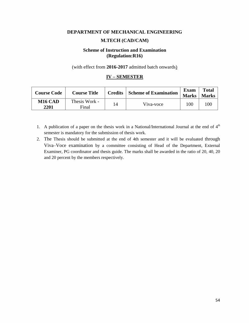
IV – SEMESTER
Course Code Course Title Credits Scheme of Examination Exam
Marks
Total
Marks
M16 CAD
2201
Thesis Work -
Final 14 Viva-voce 100 100
1. A publication of a paper on the thesis work in a National/International Journal at the end of 4th
semester is mandatory for the submission of thesis work.
2. The Thesis should be submitted at the end of 4th semester and it will be evaluated through
Viva–Voce examination by a committee consisting of Head of the Department, External
Examiner, PG coordinator and thesis guide. The marks shall be awarded in the ratio of 20, 40, 20
and 20 percent by the members respectively.