department of the army technical manual - hp...
TRANSCRIPT

DEPARTMENT OF THE ARMY TECHNICAL MANUAL
~~;~
'n
~~----------------'--------
HEADQUAR ]'ERS, DEPAR TMENT OF THE ARMYJANUARY 1959
This manual is correct to 5 J anua1'Y 1959
TM 9":"9505-2-35
TECHNICAL MANUAL}
No. 9-9505-2-35
HEADQUARTERS,
DEPARTMENT OF THE ARMY
WASHINGTON 25, D. C., 26 January 1959
ORDNANCE MAINTENANCE:MEGACYCLE METER
8898466
CHAPTER 1. INTRODUCTIONSection I. General ~ _
II. General description of grid dip meteL .III. Data _
CHAPTER 2. THEORY OF OPERATION _
3. PARTS, SPECIAL TOOLS, AND EQUIPMENT FOR FIELD AND DEPOTMAINTENANCE.
CHAPTER 4. INSPECTIONSection I. General _
II. Inspection of grid dip meteL .
CHAPTER 5. TROUBLESHOOTING _
6. GENERAL MAINTENANCE _
CHAPTER 7. FIELD MAINTENANCESection I. General _
II. Field maintenance procedures _
CHAPTER 8. DEPOTI MAINTENANCESection I. General _
II. Rebuild and rewiring _
CHAPTER 9. FINAL INSPECTION AND REPAIR STANDARDS _
ApPENDIX REFERENCES -------- _
INDEX _
AGO 3863A
Paragraphs Page
1-4 25,6 47,8 5
9-11 612-15 11
16-19 1420,21 15
22-25 1626-29 23
30-33 2434-43 29
44-46 3147-50 31
51-54 38
39
41

CHAPTER 1
INTRODUCTION
Section I. GENERAL
1. Scope
a. This manual is published for the use ofpersonnel responsible for field and depot maintenance of megacycle meter 8898466, hereinafter referred to as the grid dip meter (fig. 1).This manual does not contain informationwhich is intended primarily for the using organization, since such information is availableto ordnance maintenance personnel in the pertinent operator technical manual.
b. This manual contains description andtheory of operation of the grid dip meter. Ital.so describes troubleshooting procedures, disassembly, repair, and assembly instructions forthe grid dip meter. The instructions in thismanual are intended for maintenance specialists who have been trained in electronics maintenance practices and have had previous experience in performance testing and alinementand adjustment procedures on similar types ofequipment.
c. The appendix contains a list of currentreferences, including supply manuals, technicalmanuals, and other available publications applicable to the grid dip meter.
d. Operation, lubrication, and all maintenance operations allocated to using organizations in performing maintenance work withintheir scope for the grid dip meter are containedin the pertinent operation manuals for the system with which the grid dip meter is used.Refer to the appendix.
e. Errors or omissions in this manual will bebrought to the attention of the Commander,U. S. Army Ordnance Missile Command, ArmyRocket and Guided Missile Agency, RedstoneArsenal, Ala., ATTN: ORDXR-FMPT, usingDA Forni. 468 (Unsatisfactory EquipmentReport) .
2
2. Field and Depot Maintenance Allocation
The repair and rebuild instructions for thegrid dip meter have been divided into separatefield maintenance and depot maintenancechapters. In general, field maintenance responsibilities prescribed in this manual are directedby the allocation of maintenance parts listedin the applicable section of Department of theArmy Supply Manual ORD 8 SNL J-739 andtools listed in Type 4 SNL J-29. Depot maintenance prescribed in chapter 8 covers rebuildand rewiring of the grid dip meter. Instructions for depot maintenance are to be used bymaintenance companies in the field only whenthe tactical situation makes the repair functionimperative. Provisions of parts listed in thedepot stock guide column of the applicable section of ORD 8 SNL J-739 will be made to fieldmaintenance personnel only when the emergency nature of the maintenance to be performed has been certified by a responsible officer of the requisitioning organization.
3. Forms, Records, and Reports
a. Generat. Responsibility for the properexecution of forms, records, and reports restsupon the commanding officers of all units maintaining this equipment. However, the valueof accurate records must be fully appreciatedby all persons responsible for their compilation,maintenance, and use. Records, reports, andauthorized forms are normally utilized to indicate the type, quantity, and condition of materiel to be inspected, to be repaired, or to beused in repair. Properly executed forms convey authorization and serve as records for repair or replacement of materiel in the hands ofusing personnel and for delivery of materielrequiring further repair to ordnance shops inarsenals, depots, etc. The forms, records, andreports establish the work required, the prog-
AGO 386M
1

RA PD 406360
Figure 1. lv]egaeye1e meter (g rip clip meter) 8898466.
ress of the work within the shops, and thestatus of the materiel upon completion of itsrepaIr.
b. Authorized POI'ms. The forms generallyapplicable to units maintaining this materielare listed in the appendix. For a current andcomplete listing of all forms, refer to DA Pam310-2. For instructions on the use of theseforms, refer to FM 9-10. Additional formsapplicable to the using personnel are listed inthe operator's manual.
AGO :186:1A
c. Field Report of Accidents. The reportsnecessary to comply with the requirements ofthe Army safety program are prescribed in detail-in AR 385-40. These reports are requiredwhenever accidents involving injury to personnel or damage to materiel occur.
d. Report of Unsatisfactory Equipment 01'
Materials. Any deficiencies detected in theequipment covered in this manual, which occurunder the circumstances indicated in AR 70038, should be immediately reported in accord-
3

+ WIRES CROSSING ~ FIXED RESISTOR
0 0 PLUG AND(NO CONNECTION) JACK
+ POTENTIOMETER (OCTAL)
+ WIRES CROSSING(ARROW ALWAYS DENOTES
(CONNECTION)CLOCKWISE ROTATlON)
-0- AC OUTLET
0 FRONT PANEL CONTROL (MALE)
4:-GROUND CONNECTION (KNOB)OR RETURN
CAPACITOR $ GAS TUBE0-0
J (FEED THROUGH) --0- *INDICATES TYPE OF METEREXAMPLE:lJA - MICROAMMETER
# VARIABLE CAPACITOR
WTRIODE TUBE
-®- PANEL INDICATINGLAMP
-if- FIXED CAPACITOR
SINGLE COIL CHOKE
W~ (MAGNETIC CORE) DUODIODE TUBE
~... SPST TOGGLE SWITCH
]llltIRON CORE TRANSFORMER(CENTER TAPPED)
o..~~WAFER SWITCH 0* 'NDICATES TYPE OF* APPARATUS REPRESENTED
~BY BLOCK
cI~o------v I PHONE JACK
RA PD 236BB6~ RECEPTACLE
Figure 2. Schematic symbols.
ance with the instructions in the cited regulation.
4. Symbols and Reference Designations
A knowledge of schematic symbols, test pointsymbols, functional symbols, and referencedesignations is essential for the full utilizationof diagrams and illustrations in this manual.
a. Schematic Symbols. So far as is practicable, standard electriCal and electronic symbols are used to represent electrical and electronic elements as designated on a schematicdiagram. Figure 2 shows the symbols used inthe schematic diagrams contained in thismanual.
Note. The standard practice of using the Greek letterI" to indicate micro (one-millionth) is followed in thismanual.
b. Reference Designations. Reference designations are not to be confused with schematicor test point symbols. A system of referencedesignations is used for identifying electricalor electronic parts for assemblies or subassemblies. Reference designations are combinationsof letters and numbers and are used in thedrawings, diagrams, parts lists, and text of thismanual. The reference letters indicate thetype of part, such as resistor, amplifier, electrontube, etc. The reference number identifies theparticular part. If, for example, five resistors,either identical or different, are used in an instrument, each is given a different number.The reference designation thus identifies andlocates the part.
Section II. GENERAL DESCRIPTION OF GRID DIP METER
5. Description
a. The grid dip meter is a general purposehigh-frequency measuring device. It consistsof two units, an oscillator unit and a power
4
supply unit. The oscillator unit may be eithera high frequency (2.2 to 400 megacycles) unitor an ultra high frequency (430 to 940 megacycles) unit. Either oscillator unit may beused with the power supply unit.
AGO 3863A
b. The HF oscillator unit consists of avariable frequency oscillator which can also beoperated as a diode detector and is housed in around metal case. One of seven plug-in coilsis attached to the HF oscillator unit duringoperation to provide the desired frequencyrange. The oscillator coils are stored in therear of the power supply unit when not in use(fig. 1). The uhf oscillator unit (fig. 1) ishoused in an octagonal metal case and uses onlyone oscillator coil permanently affixed to theunit. The oscillator and power supply unitsare interconnected by - a short, flexible cable.The pow.er supply unit contains a regulatedpower supply, ammeter circuit, and a source ofmodulation for the oscillator.
c. By following special operating proceduresset forth in TM 9-9505-1-30 and TM 9-95051-45, the grid dip meter can be used withappropriate charts to calculate capacitance,inductance, mutual inductance, and Q factor.
d. The grid dip meter is supplied as an independent item of test equipment, and is also
supplied as a part of the following Type 4electronic shop sets:
Truck-Mounted Electronic Shop AN/MPM-38
Truck-Mounted Guided Missile Test Station AN/MSM-12 (with uhf 'oscillatorunit)
Semitrailer-Mounted Electronic ShopsAN/MSM-21 and AN/MSM-26
Semitrailer-Mounted Electronic ShopsAN/MSM-23 and AN/MSM-24
6. Differences Between Models
Two models of the grid dip meter are beingprocured, one with the HF oscillator unit andone with the uhf oscillator unit. The description and instructions in this manual apply toboth models. Future modifications, if any, willbe covered by DA MWO's. Refer to the current DA Pam 310-4 for any applicable DAMWO's published subsequent to the printing ofthis manual.
Section III. DATA
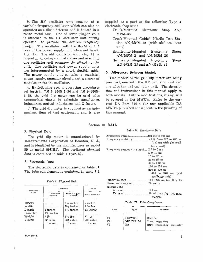
Table II. Electronic Data
Frequency range 2.2 mc to 400 mcFrequency stability ±2% from 2.2 to 400 mc
(940 mc with uhf oscillator unit).
Frequency ranges (in steps) __ 2.2 to 5 mc5 to 10 mc10 to 22 mc22 to 45 mc45 to 100 mc100 to 250 mc200 to 400 mc
430 to 940 mc (uhfoscillator unit).
Supply voltage 117 volts ac, 50/60 cyclesPower consumption 20 wattsModulation:
InternaL 120 cpsExternaL 20-volt rms for 30% mod-
ulation.
Table III. Tube Complement
7. Physical Data
The grid dip meter is manufactured byMeasurements Corporation of Boonton, N. J.,and is identified by the manufacturer as model59 or model 59UHF. The pertinent physicaldata is contained in table I (par. 8).
8. Electronic Data
The electronic data is contained in table II.The tube complement is contained in table III.
Table I. Physical Data
Uncrated CratedCharacter-
istics Oscillator
IPower supply
section section Both sections
I--
Height ------------ 6lh inches 9 inchesWidth ------------ 5lh inches 8 inchesLength 2 inches 7% inches 13 inchesDiameter 3% inches ------------ -----------Weight 1 lb. 6lh lbs. 11 lbs.Volume 89 cubic 234 cubic 1936 cubic
inches. inches. inches.
AGO 3863A
VIV2V3
Tube Type
5Y3WGTOD3/VR150955
Function
RectifierShunt regulatorHigh frequency oscillator
5

CHAPTER 2
THEORY OF OPERATION
B.
B+
WAVE METER
CIRCUITUNDER TEST
RA PD238614
Figure 3. Absorption frequency meter.
A
10. Functional Description of Major Components
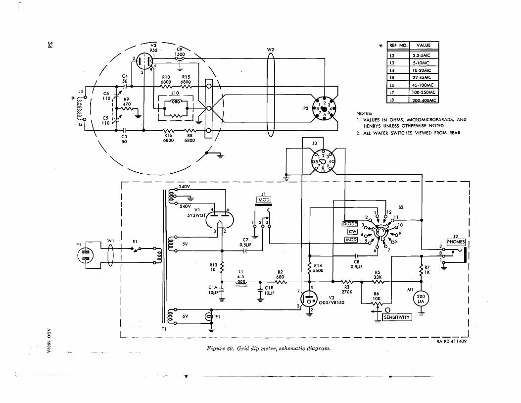
a. The block diagram (fig. 4) illustrates thesimplicity of the grid dip meter. The griddip meter consists of a power supply unit andan oscillator unit. The meter used to indicategrid current is mounted on the power supplyunit case.
b. The power supply (fig. 20) consists of apower transformer, a full-wave rectifier, api-type filter, and a gas-tube voltage regulator.The high-voltage output of the power transformer is rectified by tube VI. The output oftube VI is filtered by a pi-type filter, consisting
quency. The loss of energy from the oscillatorcauses the feedback to decrease, and this inturn produces a decrease in grid current.
9. Measurement Problem
a. Electronic equipment using resonance circuits requires a means of measuring frequency.The simplest frequency measuring device is theabsorption frequency meter (absorption wavemeter) . A, figure 3, i1lustrates a typical absorption wavemeter coupled to a tank circuit.The milliammeter in the plate circuit of theunit under test serves as the indicating device.With the absorption frequency meter looselycoupled to inductor L, the plate current of thetype in the unit under test increases slightlyas the absorption wavemeter is tuned throughthe freqeuncy of the circuit under test.
b. The elementary absorption wavemeter requires close coupling to the oscillating circuitto produce a plate current change sufficient togive visual indication on the milliammeter. Amore sensitive absorption wavemeter is obtained by adding a rectifier and a dc meter tothe elementary circuit as shown in B, figure 3.
c. In both of the absorption wavemeters described, the circuit under test must be operating with normal power applied. However, ifthe wavemeter is connected as a self-poweredoscillator, measurements can be made with nopower being applied to the circuit under test.In fact, only those components which make upthe tuned portion of the circuit are requiredto obtain a resonant measurement. When awavemeter is connected as a self-powered oscillator, it is commonly referred to as a grid dipmeter. A grid dip meter is a simple vacuumtube oscillator to which a low-range milliammeter or microammeter is added to measure theoscillator grid current. The grid dip meteris so called because the grid current will decrease or "dip" as the oscillator is tunedthrough the frequency of the unknown circuit.The "dip" in grid current is observed becausethe circuit under test absorbs energy from theoscillator when both are tuned to the same fre-
6 AGO 3863A
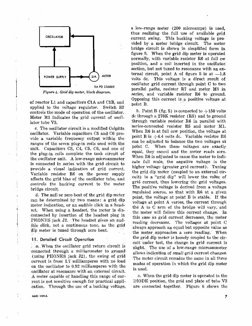
a low-range meter (200 microamps) is usedthus realizing the full use of available gridcurrent swing. This bucking voltage is provided by a meter bridge circuit. The meterbridge circuit is shown in simplified form infigure 5. When the grid dip meter is operatednormally, with variable resistor R6 at full cwposition, and a coil inserted in the oscillator.section, but not tuned to resonance with an external circuit, point A of figure 5 is at -1.8volts dc. This voltage is a direct result ofoscillator grid current through point C to twoparallel paths, resistor R7 and meter M1 inseries, and variable resistor R6 to ground.Opposing this current is a positive voltage atpoint B. '
b. Point B (fig. 5) is connected to +150 voltsdc through a 270K resistor (R3) and to groundthrough variable resistor R6 in parallel withseries-connected resistor R5 and meter M1.When R6 is at full ccw position, the voltage atpoint B is +4.4 volts de. Variable resistor R6can be adjusted to balance the two voltages atpoint C. When these voltages are exactlyequal, they cancel and the meter reads zero.When R6 is adjusted to cause the meter to indicate full scale, the negative voltage is thehigher voltage (greater grid current). Tuningthe grid dip meter (coupled to an external circuit) to a "grid dip" will lower the value ofgrid current, thus lowering the grid voltages.The positive ,voltage is derived from a voltageregulated source, so that with R6 at a givenpoint, the voltage at point B is stable. If thevoltage at point A varies, the current throughthe A to C arm of the bridge will vary, andthe meter will follow this current change. Inthis case as grid current decreases, the meterreading decreases. The voltages at point Calways approach an equal but opposite value asthe meter. approaches a zero reading.' Whenthe grid dip meter is loosely coupled to the circuit under ~est, the change in grid current isslight.. The use of a low-range microammeterallows indication of sIPaUgrid current changes.The meter circuit remains the same in all threemodes of operation in which the grid dip meteris used.
c. When the grid dip meter is operated in theDIODE position, the grid and plate of tube V3are connected together. Figure 6 shows the
METER
OSCILLATOR
~
POWER SUPPLY lJA
RA PO 236885
Figure 4. Grid dip meter, block diagram.
of reactor L1 and capacitors C1A and C1B and. 'apphed to the voltage regulator. Switch 82controls the mode of operation of the oscillator.Meter M1 indicates the grid current of oscillator tube V3.
c. The oscillator circuit is a modified Colpittsoscillator. Variable capacitors C5 and C6 provide a variable frequency output within theranges of the seven plug-in coils used with the
- unit. Capacitors C3, C4, C5, C6, and one ofthe plug-in coils complete the tank circuit ofthe oscillator unit. A low-range microammeteris connected in series with the grid circuit toprovide a visual indication of grid current.Variable resistor R6 on the power supplyaffects the grid bias of the oscillator tube, andcontrols the bucking current to the meterbridge circuit.
d. The null or zero beat of the grid dip metercan be determined by two means: a grid dipmeter indication, or an audible click in a h'eadset. When using a headset, the meter is dis~
connected by insertion of the headset plug inPHONES jack J2. The headset gives an audi~le click, not a continuous tone, as the grid'dlP meter is tuned through zero beat.
101. Detailed' Circuit Operation
;(l.. When the oscillator grid return circuit i~coimected through a milliammeter to gro,uIld(using PHONES jack J2), the swing of gridcurrent is from 1.7 milliamperes with no loadon the oscillator to 0.92 milliamperes with theoscillator at resonance with an external circuit.A meter capable of handling this range of current is not sensitive enough for practical application. Through the use of a bucking voltage,
AOO:38.63A 7

R156800
R610K
=
I SENSITIVITY
~ = ~ P25 3 -J3-
S2 (REF)
11 2
J2
R86800
I PHONES I
~
RA PO 23a554
Figure 6. Diode position, simplified 8c1vematic.
NOTES:
1.SHADED PARTS SHOWN FOR REFERENCE ONLY2.VALUES IN OHMS, MICROMIC.ROFARADS, AND
HENRYS UNLESS OTHERWISE NOTED
3.WAFER SWITCH SHOWN IN POSITION USED ONLY
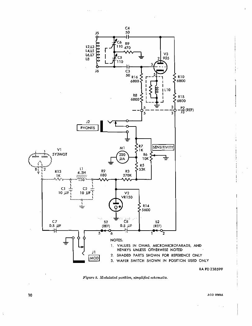
Jl,selector switch 82, and capacitor C8. Anexternal audio signal can be applied to MODjack J1 to modulate the grid dip meter. Theinternal modulating source is disconnected bythe insertion of a plug into closed-circuit :MODjack Jl.
C RA PD 238634Figure 5. Meter bridge circuit, partial schematic.
.simplified schematic with switch 82 in theDIODE position. The circuit in this conditionis that of an absorption wavemeter with diodedetector and meter indicator as described inparagraph 9b. The external circuit under testmust have power applied.
d. In the CW position (fig. 7) selector switch82 connects the plate circuit of tube V3 to theB+ supply. Tube V3 now functions as an rfoscillator, tunable over the ranges selected bythe plug-in coils. The resonant circuit to whichthe grid dip meter is coupled now acts somewhat like an absorption-type wavemeter in thatit absorbs power from the grid dip meter tankcircuit. As power is absorbed from the griddip meter, the plate-to-grid feedback is reduced, and in turn the grid current is decreased. When the grid dip meter and theexternal circuit are tuned to the same frequency, maximum power transfer occurs, andminimum grid current is drawn by tube V3 asindicated on meter Ml.
e. Circuit operation of the grid dip meter inthe MOD position (fig. 8) is identical withoperation in the CW position, except that theoscillator is modulated by the 120 cps ripplevoltage of rectifier tube Vl. The ripple voltage is applied through capacitor C7,MOD jack
·+4.4V R6 C4
10K J5 50MAX
B L2,L3 R9
L4,L5 470
L6,L7 - V3L8 955
J6 C3
50 R16 R106800 6800
8 AGO ll868A

J5C450
R106800
R156800
3 P2
3 J3(REF)
NOTES:
1. VALUES IN OHMS, MICROMICROFARADS, ANDHENRYS UNLESS OTHERWISE NOTED
2. WAFER SWITCH SHOWN IN POSITION USED ONLY
3. SHADED PARTS SHOWN FOR REFERENCE ONLY
RA PO 238600
R7 2S2
1K 12R6
10K "=
R5 ~ENSITIVIT~R3 33K
270K
Figure 7. CW position, simplified schematic.
L2, L3
L4., L5
L6, L7
L8
AGO 3863A9
R156800
-~(REF)J3
S2(REF)
R145600
~~ ISENSITIVITyl
R610K
R533K
,,=.: . .:,", I'."; ~
C80.5 JJF
S2(REF)
I~J2
C4J5 50
L2,L3 rL4,L5L6,L7 I
V3
L8 2 955L
J6
R106800
PHONES
C70.5 )JF
. \ V1,"'\~"''''\'' 5Y3WGTt ",\" .n\n'\
\ ," ,\, \ \ ..'"stTt L1
\' \ R13 4.5H R2 R3\ 1K········· 680 270K\\,........•"'\.·\.....,~•...:;iJ·~R·\···,\:-JV\A~...--J\A/"\r.....-_--I
\ ~C1 ..L C2'"
10 JJFT 10 JJFT\ \......",,,........
\"\\~'
5 6 2
J 1
[MODI
NOTES:
1. VALUES IN OHMS, MICROMICROFARADS, ANDHENRYS UNLESS OTHERWISE NOTED
2. SHADED PARTS SHOWN FOR REFERENCE ONLY
3. WAFER SWITCH SHOWN IN POSITION USED ONLY
RA PO 238599
Figure 8. Modulated position, simplified schematic.
10 AGO;38~A
CHAPTER 3
PARTS, SPECIAL TOOLS, AND EQUIPMENT FOR FIELD ANDDEPOT MAINTENANCE
12. General
Tools, equipment, and maintenance parts aresupplied to ordnance direct support maintenance units and depots for maintaining andrepairing the materiel covered in this manual.
13. Parts
Direct support maintenance parts and depotmaintenance parts are listed in appropriatecolumns of the applicable section of SupplyManual ORD 8 SNL J-739, which is the authority. for requesting replacements. Chassismounted electronic parts, and electronic partsfor which the disassembly procedure is obvious,are identified in this manual on photographicillustrations. These parts are identified on theillustrations by reference designations only.For full descriptions, values, and part numbersfor these parts, refer to the legend to the schematic diagrams (figs. 20 and 21). In each casewhere an ordnance part number is not available, the manufacturer's part number is used(par. 31c).
14. Common Tools and EquipmentStandard and commonly used tools and equip
ment having general application to this materiel are listed in Type 4 SNL J-29, section 3,and are authorized for issue by TA and TOE.
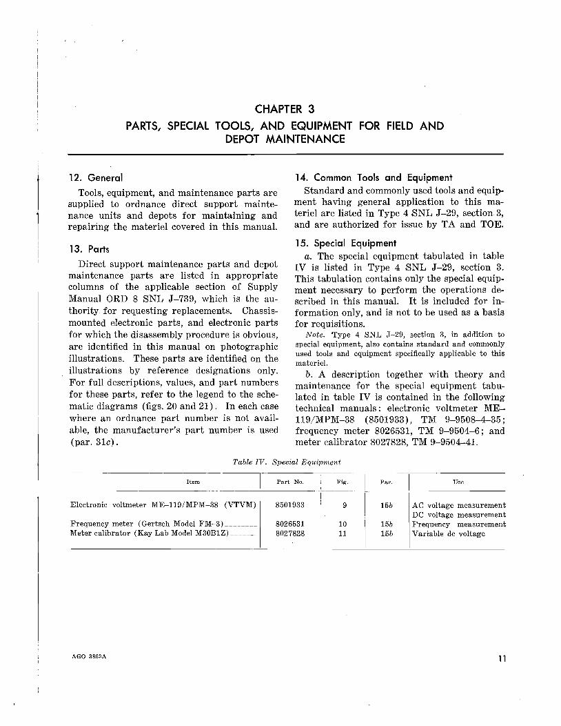
15. Special Equipmenta. The special equipment tabulated in table
IV is listed in Type 4 SNL J-29, section 3.This tabulation contains only the special equipment necessary to perform the operations described in this manual. It is included for information only, and is not to be used as a basisfor requisitions.
Note. 'Type 4 SNL J-29, section 3, in addition tospecial equipment, also contains standard and commonlyused tools and equipment specifically applicable to thismateriel.
b. A description together with theory andmaintenance for the special equipment tabulated in table IV is contained in the followingtechnical manuals: electronic voltmeter ME119/MPM-38 (8501933), TM 9-9508-4-35;frequency meter 8026531, TM 9-9504-6; andmeter calibrator 8027828, TM 9'-9504-41.
Table IV. Special Equip1nent
Par.Item ~-I
Electronic voltmeter M-E---11-9-/-M-P-M-~8 (VTVM) I
Frequency meter (Gertsch Modei FM-3) _Meter calibrator (Kay Lab Model M30B1Z) _
AGO 3863A
Part No.
8501933
80265318027828
, Fig. I
·~~-1-15b
I
10 15b11 15b
Use
AC voltage measurementDC voltage measurementFrequency measurementVariable dc voltage
11
RA PD 236892
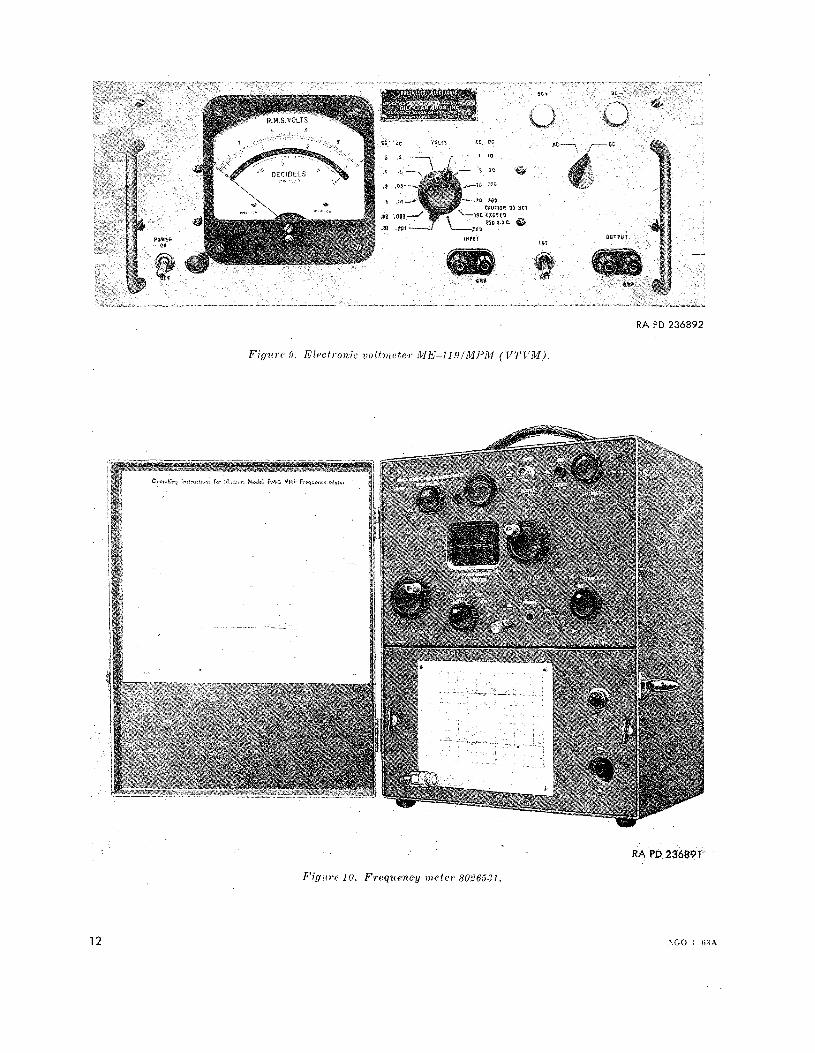
Fig1l1'C.9, E/ectronicvoltmetel' ME-ll,qIMPM (VTFM),
RAl'D236891
Figllre 10. FTequenc-y meter 8026581.
12 .'.GO I)~~A

A.. c.
METER CALIBRATOR. A\ODF.L M$ol:Hl
Figlll'c iI, ]VIefel' (,r/·/ib'/'uto/' 8027828.
0"
RA PD 236894
13
CHAPTER 4
INSPECTION
Section I. GENERAL
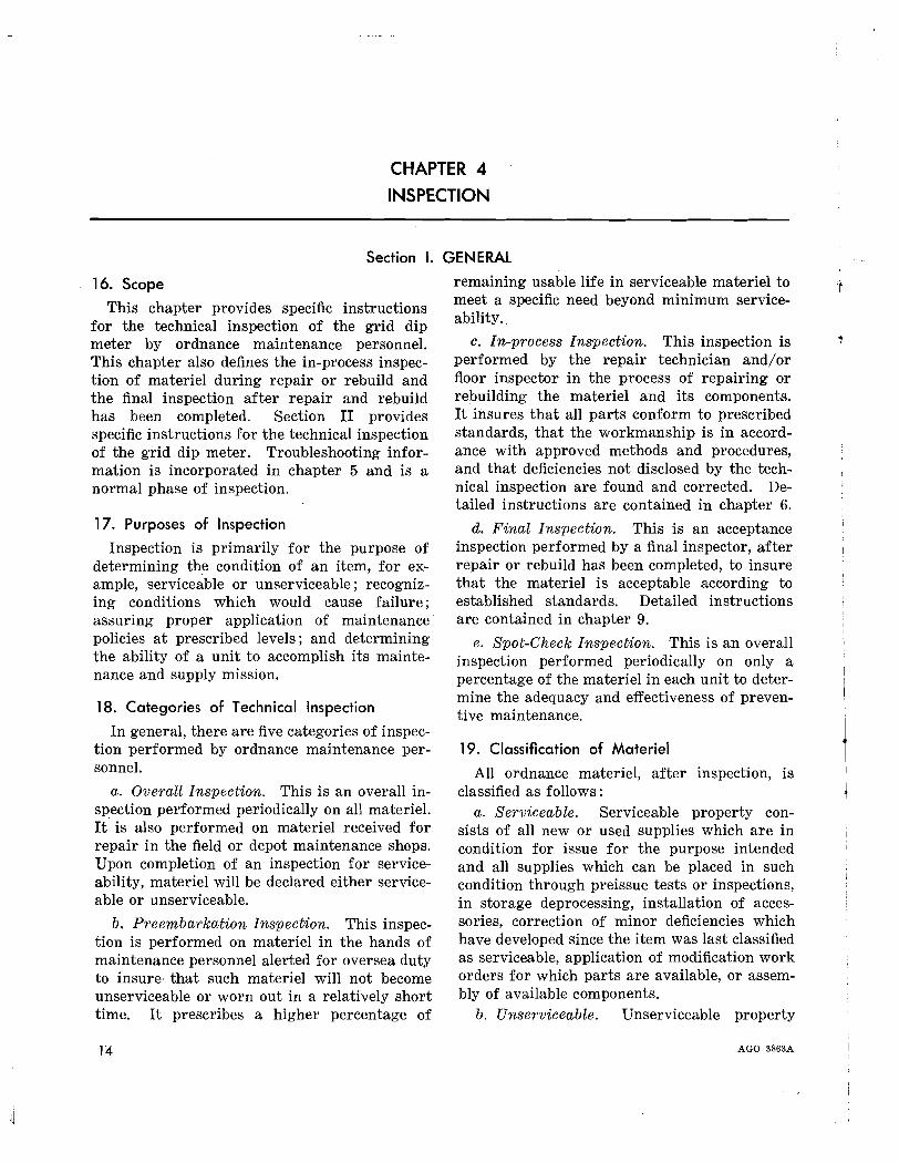
16. Scope
This chapter provides specific instructionsfor the technical inspection of the grid dipmeter by ordnance maintenance personnel.This chapter also defines the in-process inspection of materiel during repair or rebuild andthe final inspection after repair and rebuildhas been completed. Section II providesspecific instructions for the technical inspectionof the grid dip meter. Troubleshooting information is incorporated in chapter 5 and is anormal phase of inspection.
17. Purposes of Inspection
Inspection is primarily for the purpose ofdetermining the condition of an item, for example, serviceable or unserviceable; recognizing conditions which would cause failure;assuring proper application of maintenancepolicies at prescribed levels; and determiningthe ability of a unit to accomplish its maintenance and supply mission.
18. Categories of Technical Inspection
In general, there are five categories of inspection performed by ordnance maintenance per~
sonnel.
a. Overall Inspection. This is an overall inspection performed periodically on all materiel.It is also performed on materiel received forrepair in the field or depot maintenance shops.Upon completion of an inspection for serviceability, materiel will be declared either serviceable or unserviceable.
b. Preembarkation Inspection. This inspection is performed on materiel in the hands ofmaintenance personnel alerted for oversea dutyto insure, that such materiel will not becomeunserviceable or worn out in a relatively shorttime. It prescribes a higher percentage of
remaining usable life in serviceable materiel tomeet a specific need beyond minimum serviceability.
c. In-process Inspection. This inspection isperformed by the repair technician and/orfloor inspector in the process of repairing orrebuilding the materiel and its components.It insures that all parts conform to prescribedstandards, that the workmanship is in accordance with approved methods and procedures,and that deficiencies not disclosed by the technical inspection are found and corrected. Detailed instructions are contained in chapter 6.
d. Final Inspection. This is an acceptanceinspection performed by a final inspector, afterrepair or rebuild has been completed, to insurethat the materiel is acceptable according toestablished standards. Detailed instructionsare contained in chapter 9.
e. Spot-Check Inspection. This is an overallinspection performed periodically on only apercentage of the materiel in each unit to determine the adequacy and effectiveness of preventive maintenance.
19. Classification of Materiel
All ordnance materiel, after inspection, isclassified as follows:
a. Serviceable. Serviceable property consists of all new or used supplies which are incondition for issue for the purpose intendedand all supplies which can be placed in suchcondition through preissue tests or inspections,in storage deprocessing, installation of accessories, correction of minor deficiencies whichhave developed since the item was last classifiedas serviceable, application of modification workorders for which parts are available, or assembly of available components.
b. Unserviceable. Unserviceable property
AGO 3863A
III,

consists of all supplies which are not serviceable (i. e., does not satisfy the definition in aabove). The definition of unserviceable property is further broken down into the following
subclassifications: Property which is unserviceable but economically reparable, and propertywhich is unserviceable and not economicallyreparable.
Section II. INSPECTION OF GRID DIP METER
20. Inspection of the Mechanical Components ofthe Grid Dip Meter
a.. The grid dip meter must be clean and dryinside and out.
b. The painted cases must be in a good stateof preservation.
c. The selector control, sensitivity control,and tuning control must be intact, and functionnormally without binding.
d. The meter scale, frequency indicationscale, and all other essential markings must beclearly defined and easily read.
e. The meter needle must not stick at anypoint.
f. The meter and tuning control windowsmust not be cracked, scored, or discolored.
AGO 3863A
21. Inspection of Electrical Components of theGrid Dip Meter
a. Check resistors for cracks, swelling, ordiscoloration.
b. Check to see that the dual electrolyticcapacitor is not leaking.
c. Check power transformer and choke forindications of overheating, such as blisteredpaint, smoke, or leaking sealing compound;listen for hum which might indicate loose corelaminations.
d. Check the tubes to see that they are notloose in their sockets, and that none of the keysare broken.
e. Check to see that the variable tuningcapacitor supports are not broken.
15

CHAPTER 5
TROUBLESHOOTING
22. Purpose
Troubleshooting is a systematic isolation andremedy of malfunctions and defective components by means of symptoms and tests. Closeadherence to the procedures covered herein willmaterially reduce the time required to locatetrouble and restore the equipment to normaloperation.
23. Scope
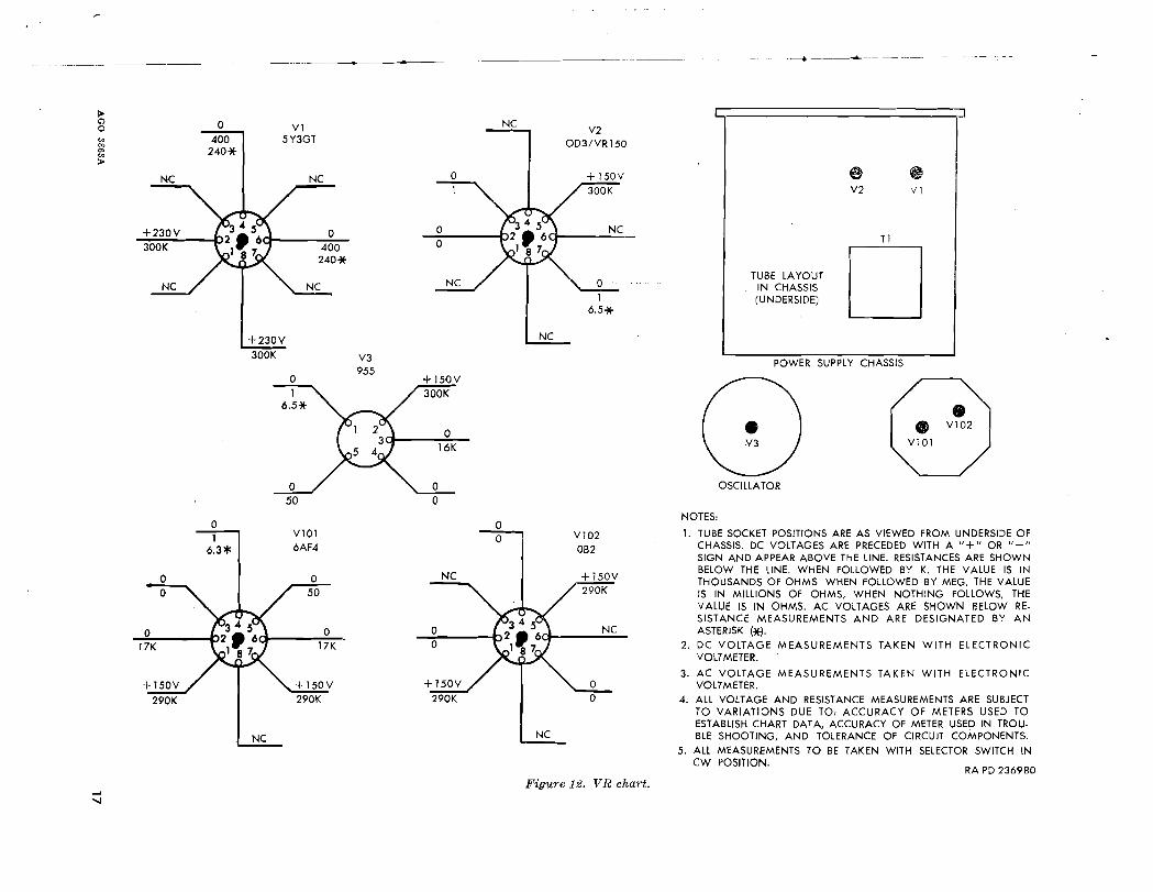
The tests and remedies provided herein aregoverned by the scope of level of ordnancemaintenance. The operational check andtroubleshooting table (table V, par. 24) indicates the step-by-step procedure for locatingdefective components of the grid dip meter.In this table, normal indications are given with
16
the probable cause of malfunction. Methodsfor correcting the trouble are given, exceptwhen the method of correction can be expectedto be obvious to the trained technician. A voltage and resistance chart is shown in figure 12and is used as an aid in troubleshooting procedures.
24. Operational Check and Troubleshooting ofGrid Dip Meter
The operational check and troubleshootingtest chart provides a step-by-step procedure ofoperation necessary to determine what component of the grid dip meter is at fault. Theoperational check and troubleshooting chart ofthe power supply is contained in table V, test 1.The operational check and troubleshooting frequency test are shown in table V, tests 2 and 3.
AGO 3E63A
--------------+- -~----------e. ----~---
>Q 0 Vl0
'" 400 5Y3GT00
240*0>
'">NC NC
T1
DVI
eV2
TUBE LAYOUTIN CHASSIS(UNDERSIDE)
V2OD3/VR150
NC
NC
oo
o
o400240*
300K+230V
+230V
300K
NC
POWER SUPPLY CHASSIS
OSCILLATOR
RA PD 2369BO
oo
o17K
+150V
290K
o
NC
V1016AF4
o50
o17K
+150V290K
NC
oo
aa V102
OB2
+150V290K
NC
NC
NOTES,
,. TUBE SOCKET POSITIONS ARE AS VIEWED FROM UNDERSIDE OFCHASSIS. DC VOLTAGES ARE PRECEDED WITH A "+" OR "-"SIGN AND APPEAR ABOVE THE LINE. RESISTANCES ARE SHOWNBELOW THE LINE. WHEN FOLLOWED BY K, THE VALUE IS INTHOUSANDS OF OHMS. WHEN FOLLOWED BY MEG, THE VALUEIS IN MILLIONS OF OHMS, WHEN NOTHING FOLLOWS, THEVALUE IS IN OHMS. AC VOLTAGES ARE SHOWN BELOW RE.SISTANCE MEASUREMENTS AND ARE DESIGNATED BY ANASTERISK (*J.
2. DC VOLTAGE MEASUREMENTS TAKEN WITH ELECTRONICVOLTMETER.
3. AC VOLTAGE MEASUREMENTS TAKEN WITH ELECTRONICVOLTMETER.
4. ALL VOLTAGE AND RESISTANCE MEASUREMENTS ARE SUBJECTTO VARIATIONS DUE TO, ACCURACY OF METERS USED TOESTABLISH CHART DATA, ACCURACY OF METER USED IN TROU·BLE SHOOTING, AND TOLERANCE OF CIRCUIT COMPONENTS.
5. ALL MEASUREMENTS TO BE TAKEN WITH SELECTOR SWITCH INCW POSITION.
Figure 12. VR chart.

MULTIMETERTS-352B/U
~
V2-5
117V AC _ VARIABLE GRID DIP + + VTVMTRANSFORMER - METER
2352086 POWER SUPPLY CHASSIS GRD8501933
- -
B
MULTIMETER VTVMTS-352B/U 8501933
117V AC~ - +
!CHASSIS GRD
VARIABLE GRID DIP - - METER
TRANSFORMER METER CALIBRATOR
2352086 POWER SUPPLY V2-5 8027828
+ +
c-
MULTIMETERTS- 352B/U
H
CHASSIS GRD
117V AC _ VARIABLE GRID DIP VTVMTRANSFORMER - METER 8501933
2352086 POWER SUPPLY V2-5
tI
18
Figure 13. Power supply test equipment connections.RA PO 236890
AGO 3863A

>.~
o
--~-.~."._-------------
Table V. Operational Check an,d Troubleshooting of Grid Dip Meter
: Test No. 1. Power Supply'"> PRELIMINARY INSTRUCTIONS: Connect variable transformer 2352086 and grip dip meter power supply as shown in A, figure 13.
Plug variable transformer into 117v ac outlet. Set variable transformer at 117 volts. Allow a 15 minute warm upperiod before continuing each test.
StepControl settings and
operation of test equipment Control settings and operation of unit Normal indication Possible cause of abnormal indication
Maximum of 15 millivolts________ Capacitor C1, C2, or tube V2 defective.
VTVM reading varies a maximum Resistor R2 or R13, reactor L1, orof ±5 volts. tube V2 defective.
Place selector switch ,82 to CW 150 volts dc ±7 volts____________ Power transformer T1 or tube V1Place off-on switch Sl to on. defective.
1A
1B
1C
1D
Connect power supply test circuitas shown in figure 13A.
Set VTVM to 300 volt dc range.Connect power supply regulation
test circuit as shown in figure13B.
Set meter calibrator at 5 volts lessthan the reading obtained undernormal indication column of steplA, being sure to observe polarities as shown in figure 13B.
Set VTVM to 10 volt dc range.Vary the variable transformer from
105 to 129 volts.Connect power supply ripple test
circuit as shown in figure 13C.Set VTVM to 1 volt ac range.
Place selector switch S2 to MOD__ 120 cps tons heard in phones _Connect phones to PHONES con-
nector J2.
Capacitor C7 or C8, connector J1or J2, switch S2, tube V1, orpower transformer T1 defective.
Test No.2. Frequency Test (H-F Oscillator Unit)
PRELIMINARY INSTRUCTIONS: ConneCt the grid dip meter and the frequency meter to 117 volts ac. Allow a 15-minute warm up period.Couple the coil used in the grid dip meter to the antenna of the frequency meter. The proper coupling can be obtained by placing the oscillator section of the grid dip meter on top of the frequency meter with the coil about fourinches from the antenna. The coupling should not be any closer than needed to prevent possible errors in readings.
.. Note. The frequency meter measures fundamental frequencies from 20 to 40 me. All frquencies checked outside this range must bear a harmonic relationship to the fundamental frequency used.
~
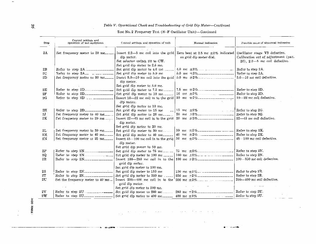
0,Table V. Operational Check and Troubleshooting of Grid Dip Meter-Continued
Test No.2 Frequency Test (H-F Oscillator Unit)-Continued
Step-'control settings and
operation of test equipmen t Control settings and operation of unit Normal indication Possible cause of abnormal indication
2A
2B2C2D
Set frequency meter to 20 mc _
Refer to step 2A_' :.. _Refer to step 2A _Set frequency meter to 30 mc _
Zero beat at 2.5 inc ±2% indicated Oscillator stage V3 defective.on grid dip meter dial. Calibration out of adjustment (par.
26), 2.2-5 mc coil defective.
4.0 mc ±2% Refer to step 2A.5.0 mc ±2%____________________ Refer to step 2A.5.0 mc ±2%____________________ 5.0-10 mc coil defective.
2E2F2G
Refer to step 2D _Refer to step 2D _Refer to step 2D _
7.5 mc10 mc10 mc
±2% _±2% _
±2%------------------7 -
Refer to step 2D.Refer to step 2D.10-22 mc coil defective.
2H2J2K
2L2M2N
Refer to step 2D _1:et frequency meter to 40 mc _E'et frequency meter to 20 mc _
Set frequency meter to 30 mc _1:et frequency meter to 40 mc _Set frequency meter to 25 mc _
mcmcmc
mcmcmc
±2% Refer to step 2G.±2% Refer to step 2G.±2% 22-45 mc coil defective.
±2% Refer to step 2K.±2%____________________ Refer to step 2K.±2%_____________________ 45-100 mc coil defective.
2P Refer to step 2N________________
2Q Refer to step 2N________________
2R Refer to step 2N________________
75 mc ±2%____________________ Refer to step 2N.100 me ±2% .,-_____ Refer to step 2N.100 mc ±2% 100-250 mc coil defective.
>l;'lo
2S2T2U
2V2W
Refer to step 2N _Refer to step 2N _
Set the frequency meter to 40'mc__
150 mc ±2%_____________________ Refer to step 2R.250 mc ±2%____________________ Refer to step 2R.
the 200 mc ±2%______ 200...,.,.400 mc coil defective.

--------------------------......."..,~~
Test No.3. Frequency Test (UHF Oscillator Unit)
PRELIMINARY INSTRUCTIONS: Connect the grid dip meter and the frequency meter to 117 volts ac. Allow a l5-minute warm up period.Couple the coil used in the grid dip meter to the antenna of the frequency meter. The proper coupling can be obtained by placed the oscillator section of the grid dip meter on top of the frequency meter with the coil about fourinches from the antenna. The coupling should not be any closer than needed to prevent possible errors in readings.
Note. The frequency meter measures fundamental frequencies from 20 to 40 mc. All frequencies checked outside this range must beara harmonic relationship to the fundamental frequency used.
Possible cause of abnormal indication
Oscillator stage VlOl defective.Calibration out of adjustment (par.
26), R-F coupling coil defective.Refer to step 3A.Refer to step 3A.
Normal indicationControl settings and operation of unitControl settings and
operation of test equipment
I
Set frequency meter to 40 mc_____ Set selector switch S2 to CW Zero beat at 440 mc ±2% indicatedSet grid dip meter to 440 mc.____ on grid dip meter dial.
Refer to step 3A________________ Set grid dip meter to 680 mc______ 680 mc ±20/0 . _Refer to step 3A________________ Set grid dip meter to 920 mc 920 mc ±20/0 _
3A
3B3C
__~J_-----

25. Alinement and Calibration of the Grid DipMeter
a. HF Oscillator Unit. Whenever the oscillator tube (V3) becomes weak or defective andis replaced, recalibration of the grid dip meteris necessary because of the difference in tubeinterelectrode capacitance. When: replacingthe dial cover leave the three cover retainingscrews slightly loose so that it will be possibleto rotate the cover. Rotate the tuning controlknob as far as it will go clockwise. Loosenthe three dial cover retaining screws and turnthe dial cover so that the hairline is alinedwith the long end mark on the frequency dial.Tighten one of the three cover retaining screwsfirmly. Place the 22 to 45 mc coil into the griddip meter. Set control knob of grid dip meterat 30 mc. Set frequency meter 8026531 (TableIV, par. 15) at 30 mc. Couple grid dip meterto the antenna of the frequency meter.
Note. Refer to preliminary instructions of operational check, Table V, (par. 24) Test 2.Rotate tuning control knob of grid dip meteruntil a null indication is heard. Loosen the retaining screw on the dial cover of the oscillatorsection and rotate the cover until the hairlmeis alined with the 30 mc graduation. Tightenthe three retaining screws firmly. If unable tocalibrate because the cover will not rotate farenough, loosen the three screws retaining thedial, and rotate the dial to compensate.
22
b. UHF Oscillator Unit. When the oscillatortube (V101) in the oscillator unit requires replacement, a slight adjustment may be necessary. First, try several replacement tubes(type 6AF4) and select a tube to match theoriginal dial calibration as nearly as possible. I
Remove the tuning knob and the cover of theoscillator unit as follows: remove the screw inthe cup washer at the center of the cover andremove the screws on the right and left edgesof the top cover. (Do not disturb the screwsabove the name "MEGACYCLE METER".)Lift the cover off. Also remove the side coverby removing the four screws holding the side inplace. Replace the defective tube.
Note. Refer to preliminary instructions of operational check, Table V, (par. 24) Test 3.Set the frequency control shaft (knob has beenremoved) at 600 mc. Set frequency meter usedin performing the alinement at 600 mc. Couplegrid dip meter to the antenna of the frequencymeter. Rotate the tuning control of the griddip meter until a null indication is heard. Ifselection of the tube does not provide an exactmatch, loosen the two screws on the cover abovethe name "MEGACYCLE METER" holdingthe hairline fiducial in position and move thefiducial slightly. Retighten the screws, and replace the side and the cover of the oscillatorunit.
AGO ~86SA
,
CHAPTER 6GENERAL MAINTENANCE
,26. General
General maintenance of the grid dip meterconsists of all standard shop practices and procedures required to repair and maintain theequipment in serviceable condition, plus certainspecial procedures designed to accomplish adequate maintenance where unusual conditionsprevail within the equipment. General maintenance procedures are not intended to includeoperational checks, tests, troubleshooting, orperformance measurements, and do not requirethe use of special· test instruments, as thesepractices are covered in chapter 5. Generalmaintenance does require, however, the use ofcommon and special tools and bulk suppliessuch as abrasives, solvents, sealing compounds,paints, and lubricants.
27. Scope
This general maintenance chapter providesadequate references to appropriate Departmentof the Army Technical Manuals, Technical·Bulletins, or other Army publications for procedures where shop methods and practice havealready been established. Specific maintenanceprocedures peculiar to the grid dip meter arecontained in the repair and rebuild chapters.
28. Use
The repair and rebuild portions of thismanual are divided into separate field (chapter7) and depot (chapter 8) maintenance instructions. In general, the field maintenance responsibilities prescribed are direCted by the allocation of maintenance parts listed in the applicable section of Department of the Army Supply Manual ORD 8 SNL J-739 and tools listedin Type 4 SNL J-29, section 3. The general
AGO 3863A
maintenance shop practices and procedurespertain to either or both field and depot maintenance, as required. Repair and rebuild information in both the field and depot maintenance chapters are based upon the assumption that personnel are familiar with the pertinent general maintenance procedures coveredin this chapter. That is, specific references arenot made to individual general maintenanceprocedures, except where danger to equipmentor personnel is involved. These references areomitted because they would be too numerous.In view of this, it is especially important thatpersonnel using this manual be familiar withthe content of this chapter.
29. Shop Methods and Practices
Established procedures for shop methods andpractices will be found in Department of theArmy Technical Manuals, Technical Bulletins,and other Army publications. General procedures applicable for the repair and maintenance of the grid dip meter will be found inthe following list.Chassis rewiring TB 5-283-2Cold weather maintenance TB ORD 193Desert maintenance TB SIG 75Lubrication TM 9-2835Moisture and fungus-proofing .TB ORD 350Painting TM 9-2851
Repair of meters, switches, and con- TB SIG 24nectors.
Soldering TB SIG 222Tropicalization TB SIG 72Troubleshooting and repair of radio TM 11-4000
equipment.These references are not to be construed asauthority for the performance by field maintenance units of those functions which are restricted to depots and arsenals. Refer to paragraph 28.
23
CHAPTER 7
FIELD MAINTENANCE
Section I. GENERAL
30. ScopeThis chapter contains maintenance informa
tion covering the grid dip meter that is withinthe scope of field maintenance personnel. Thescope of field maintenance is determined by thelisting of field maintenance parts in the applicable section of ORD 8 SNL J-739 and the listing of special tools authorized to field maintenance personnel in Type 4 SNL J-29, section 3.
31. Referencesa. General maintenance procedures are furn
ished in chapter 6. Individual references togeneral maintenance are not made within thischapter. It is, therefore, especially importantthat personnel become familiar with the content of chapter 6.
b. Operation and organizational maintenance of the grid dip meter, as it is used inelectronic shop AN/MPM-38, is covered inTM 9-9505-1-30.
c. Operational check and troubleshootinginformation is contained in chapter 5. Schematic diagrams are included at the end of chapter 8. The legends for the schematic diagramslist all replaceable electronic parts. Thelegends for figures 14, 16, and 18 list the balance of the replaceable parts. At the time ofprinting of this manual, manufacturer's partnumbers were used, as ordnance part numberswere not available for all parts. The H numbers in the legends are reference drawing numbers of the Measurements Corporation. Themanufacturer's code for parts listed in thelegend for the schematic diagram are:Mir's code Manufacturer
H Measurements CorporationDyR Cornell DubilierC . Chicago Transformer CompanyQ , International Resistance CompanyPR Wirt CompanyMC Industrial Transformer Company
24
32. Repair and Maintenance
a. P7'ecautions. Before attempting to replace parts or to repair assemblies, be sure tofollow the troubleshooting procedures (chapter5) in order to isolate the source of trouble correctly. Incorrect replacement of parts and inadequate repair practices can complicate existing trouble. Use the proper tools (pars. 12-15)for each replacement and repair procedure.Fo]owing the completion of repair or replacement, it sometimes is necessary to clean orretropicalizeparts or subassemblies. Refer toparagraph 29 for reference to general instructions on such procedure.
b. Replacement Policies. Most electroniccomponents are not economically reparable andgenerally, when defective, are to be replacedrather than repaired. Capacitors, resistors,and, in general, all sealed or potted components,such as transformers and coils, are to be replaced when defective. Defective unsealedswitches are reparable when the defect consistsof dirty or corroded contacts; otherwise, theymust be replaced. If possible, replace a defective part with an exact duplicate. When aduplicate is unavailable, substitute a part withsimilar electrical characteristics and equivalenttolerance. Be particularly careful in selectingthe replacements for resistors, capacitors, andtubes. In signal circuits, substitute parts withthe same physical sizes to avoid altering circuitinductance and capacitance and affecting highfrequency response. It is permissible to use areplacement with a voltage rating greater, butnever less, than that for the part to be replaced.See the parts identity illustrations (figs. 14-18)when replacing parts in order to locate thepart position and terminal connections. Referto paragraph 33 of this chapter for standardsapplying to handling of disassembled compon-
AGO 38631\
,+I•i

c
R13 II J3
D (NOT SHOWN) \
A-Handle, H-2024B-Bal' knob: IV, inches. H-4133C-AC cord: molded plug, H-704
D-lVIounting foot: felt cushion, H-4204-1E- Cable clampF-Round knob: fluted (no marking') H-27\J1
Figlu'e 14. Power supply unit, parts identifieatiOJI.
ents and to paragraph 29 for references tosoldering and dressing wire.
Note. Parts identity illustrations (figs. 14-18) identify electronic parts by reference designation only.Refer to the legends to the schematic diagrams (figs.20 and 21) for full description, values, and part numbersfor the parts.
c. Replacem,ent Practices. Before unsoldering any connection prior to removing components to be replaced, be sure to remove tropicali-
zation varnish on the connection. Observepolarity markings on such parts as capacitors.Mount electronic components on terminals sothat the color code reads from top to bottom orfrom left to right. Wrap leads clockwisearound the bottom terminals. Avoid obscuringany identification markings on the terminalboard and chassis. In any case, try to mounta replacement in the position formerly occupied by the part being replaced. If any wires
25
WHITE
AC CORD
3
R3
3
R2
2
TSl
RA PD 238635
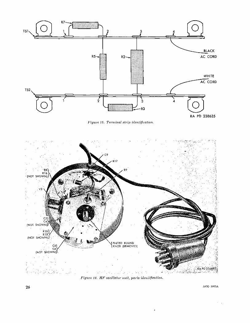
Figure 15. Terminal strip identification.
Figure 16. HF oscillator unit, pa1·ts identification.
26 AGO 3863A

Figw'e 17. G1'id dip meter, plug-in eoils identifieation.
are moved during the process of part replacement, restore them to their original positionswhen replacement is complete. When replacing mechanical parts such as structural members that attach with screws or bolts, place thelockwashers next to the nut or screw whichturns. When necessary, place a flat washerbetween the lockwasher and the stationarysurface.
d. Replacement Definit·ions. Repair of electronic materiel can be accomplished in one offive ways. The first is replacement of a defective part and is preferred when possible. Thesecond is repair of a portion of a part, such asthe reconstruction of a broken socket terminal.The third is rebuild of an entire part, such asthe cutting of a form and the winding of acoil to make a reactor. The fourth is substitution of an equivalent part, such as replacement of a 500-ohm 2-watt resistor by two 1000ohm I-watt resistors connected in parallel.
AGO 3863A
The last is an emergency fix which can be considered temporary only. Parts must be repaired only when replacement is impossible,and rebuilt or improvised only when repair isimpossible. An emergency fix only partiallyrestores defective materiel and must be usedonly when repair is impossible or when theurgency of a tactical situation in the field makesany other method of placing materiel into operation impossible. Emergency measures willbe taken only when the maintenance to be performed has been authorized by a responsibleofficer.
33. Handling of Disassembled Parts
Always assume that materiel disassembledby one person will be assembled by another.Therefore, unless the method of assembly isobvious make a suitable sketch showing theorientation of the components before disassembly. Note the position of components and wir-
27

RA PD 406395
V101
V102
A
B
Cl0l THROUGH Ci04ASSEMBLY L101
,/
V102AB
V10l
'-CJ05R102C106
.....-.::~-......., (INSIDE
CI01-C104SHIELD)
C
C101
R101(NOT SHOWN)
C107C108L1 02L103L104L105
(INSIDEC101-C104
SHIELD)
WlOPP101~
(NOT SHOWN)) I.
E
A-Tube shield. TSI02U03B- Tube socket. H-5374C-Dial scale, H-2788-A
D-Fidt:eial, H-2788-BE- Knob, H-2788
PigU.1'C 78, UHP oscillator unit, jJrLl'ts idcntiji.crttioJl,
ing, and if several leads are involved, tag eachso that it can be connected correctly. As eachmetal component is removed, establish its exactposition in relation to other components bysuitably scribed reference marks. However,never scribe marks on contact surfaces such asthreads and slide rails. Note polarity markings on capacitors and other components somarked. Use a parts tray or other suitablereceptacle so that components, as removed, can
be placed in the positions they are to occupy inrelation to the complete assembly. Alwayskeep each component in its relative positionuntil it is to be installed. When in doubt as towhat position a component or wire is to occupy,refer to the component identity illustrations(figs. 14-18) and to the schematic diagrams(figs. 20 and 21). Keep hardware in a sackattached to the disassembled component if installation is not to be made immediately.
28 AGO 3863A
Section II. FIELD MAINTENANCE PROCEDURES
I
~;
34. Disassembly of Power Supply
The bottom plate and power· supply chassismust be removed from the power supply casebefore any components of the front panel ofthe case can be removed. The bottom plate isremoved by removing four self-tapping screwswhich are located at the base of the sides of thepower supply case. The power supply chassisis removed by removing four self-tappingscrews which are located vertically along thesides of the power supply case. Pull the powersupply chassis down and out of the powersupply case to facilitate further disassemblyprocedures. Tag all wires leading to components that are to be removed, and record theorientation of each component before it is removed to facilitate reassembly.
35. Repair of Power Supply
No special procedures are required to repairthe power supply unit of the grid dip meterother than standard shop procedures as described in chapter 6. All direct support fieldreplaceable parts for the power supply unit areillustrated and identified in figures 14 and 15.All parts are schematically identified in figure20.
36. Assembly of Power Supply
After defective components have been replaced and all wiring completed, the powersupply chassis is installed first. Place thepower supply chassis into the power supplyc;ase and aline the four mounting holes, theninsert the mounting screws and tighten. Placethe bottom plate into the power supply case andaline the mounting holes, then insert the mounting screws and tighten.
37. Disassembly of HF Oscillator and OscillatorCase
The dial cover and calibrated dial must beremoved before any part of the oscillator ismade accessible. Loosen the two set screws onthe tuning control knob and remove the knob.Before removing the dial cover from the case,mark its position with reference to bottom portion of case. Remove the three round headscr~ws from the side of the case, th~n lift off
AGO 3863A
the dial cover. Before removing the calibrateddial, turn the tuning control shaft in a fullclockwise direction, and locate some point onthe dial in relation to some point ort the case.Remove the three screws on the top of the dial,and remove the dial and three fiber washers.
Caution: The dial should be kept face up andcovered during the time it is out of the case.Care should be taken not to smear or mar thecalibrated dial. The components of the oscillator are fragile and easily bent or damaged;therefore, care should be exercised during disassembly procedure.All components of the oscillator assembly areaccessible, and normal repair procedures can beused to repair or replace components of theoscillator assembly. Care must be exercised tokeep the placement of parts and the lead lengththe same as originally installed.
38. Repair of HF Oscillator
No special procedures are required to repairthe HF oscillator unit of the grid dip meterother than standard shop procedures as described in chapter 6. All direct support fieldreplaceable parts for the oscillator are illustrated and identified in figures 16 and 17.Electronic components are schematically identified in figure 20.
39. Assembly of HF Oscillator and OscillatorCase
After components have been installed, thecalibrated dial should be installed as follows.Turn the tuning control shaft in a full clockwiseposition. Place the thin fiber washer on thecalibrated dial mounting plate and aline theholes. Place the calibrated dial on the mounting plate, and orient the dial with the point onthe case in the position described in paragraph37. Place the heavy fiber washer into the calibrated dial and aline the insert with the holesin the mounting plate. Place the remainingfiber washer on top of the dial and aline theholes. Then insert and tighten the threescrews. Place the cover on the oscillator caseand aline the cover to alinement mark as recorded in paragraph 37. Insert and tighten thethree roundhead screws.
29
Note. The grid dip meter must be calibrated whenever the top cover is removed. Refer to the alinementand calibration instructions (par. 25).
40. Disassembly of UHF Oscillator Unit
The tuning knob must be removed first.Then, remove the screw in the sealed cupwasher at the center of the hexagon top cover.Remove the screws located on the right andleft edges of the cover.
Caution: Do not disturb the screws above thename "MEGACYCLE METER" on the cover.
Lift off the cover. Remove the four screws inthe side of the case, and remove the side. Thismakes all replaceable or reparable componentsof the oscillator unit accessible, and normal repair procedure can be used to repair or replacecomponents of the oscillator unit. Extremecare must be exercised to lceep the placementof parts and the lead length the same as originally installed. Disassembly beyond this pointis not recommended, as critical adjustmentsmay be disturbed.
41. 'Repair of UHF Oscillator Unit
No special procedures are specified for the
TUNING CONTROL SHAFT 1OIL AT 6 MONTH INTERVALS I
VARIABLE CAPACITORROTOR BEARING, OIL
'. AT 6 MONTH INTERVALS......,
repair of the uhf oscillator unit other thanstandard shop procedures described in chapter6. All direct support field replaceable partsare illustrated and identified in figure 18.Electronic components are schematically identified in figure 21. Mechanical parts withinthe UHF oscillator unit require precision assembly and are not separately replaceable, except for common hardware.
42. Assembly of UHF Oscillator UnitAssembly of the uhf oscillator unit is the
reverse of the disassembly procedures describedin paragraph 40.
Note. The calibration of the grid dip meter must bechecked as outlined in paragraph 25, after reassemblyof the uhf oscillator unit.
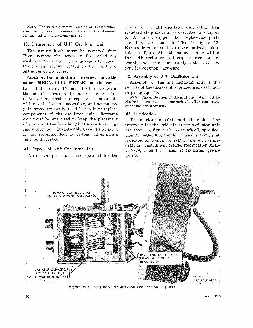
43. LubricationThe lubrication points and lubrication time
intervals for the grid dip meter oscillator unitare shown in figure 19. Aircraft oil, specification MIL-O-6085, should be used sparingly atindicated oil points. A light grease such as aircraft and instrument grease, specification MILG-3278, should be used at indicated greasepoints.
30
Figu?'e 19. Grid dip meter HF oscillator unit, tub?'ication points.
AGO 3863A

CHAPTER 8DEPOT MAINTENANCE
Section I. GENERAL
44. Scope
This chapter contains maintenance information covering the rebuild and rewiring of thegrid dip meter.
45. References
a. General maintenance procedures and shoppractices are discussed in chapter 6. Individual references to general maintenance arenot made within this chapter. It is, therefore,especially important that personnel becomefamiliar with the content of chapter 6.
b. Operation and organizational mainte-
nance of the grid dip meter as it is used inelectronic shop AN/MPM-38, is contained inTM 9-9505-1-30.
c. Theory of operation is contained in chapter 2. Operational check· and troubleshootinginformation is contained in chapter 5. A schematic diagram is contained at the end ofchapter 9.
46. Handling Disassembled Parts
The procedures for handling disassembledparts and the procedures for disassembly arecovered in chapter 7.
Section n. REBUILD AND REWI:RING
locate the reference symbol and terminal number at either wire end, in the To column. TheFrom column will indicate the correct termination of the opposite end. Figure referencesshowing the physical location of each termination are given.
c. To reattach loose wires after replacing acomponent part, locate the reference symbol ofthe replaced part on the list. ,Each terminalon this part is identified with its correct connection or termination point. Connect thewires accordingly.
d. To rewire the power supply chassis, referto the parts identification illustrations (figs. 14and 15) to determine which component partshould be wired first. Then refer to the wirelist for the proper wire to use and for the correct terminations. Third, refer to the partsidentification illustration for the general position and dress of the wire. Place the new wirein the general position of the original wire.Repeat these, steps for each wire installed.
48. Wire List
a. The wire list (table VI) contains information that enables the technician to replace asingle wire, reconnect a wire, trace wiring connections, or perform a complete rewiring. Thelist is in order by electronic part referencedesignation, and gives a description of the wireconnected to each terminal of each part, as wellas the destination or opposite termination ofeach wire. Each wire and each termination appears twice in the list; once in the To columnand once in the From coluITm.
b. To trace a wire or to install a single wire,
47. General
This section contains maintenance instructions for the rebuild and rewiring of the griddip meter. Rewiring instructions, along withthe field maintenance procedures in chapter 7,are sufficient to enable experienced techniciansto rebuild the grid dip meter.
it.
AGO 3863A 31
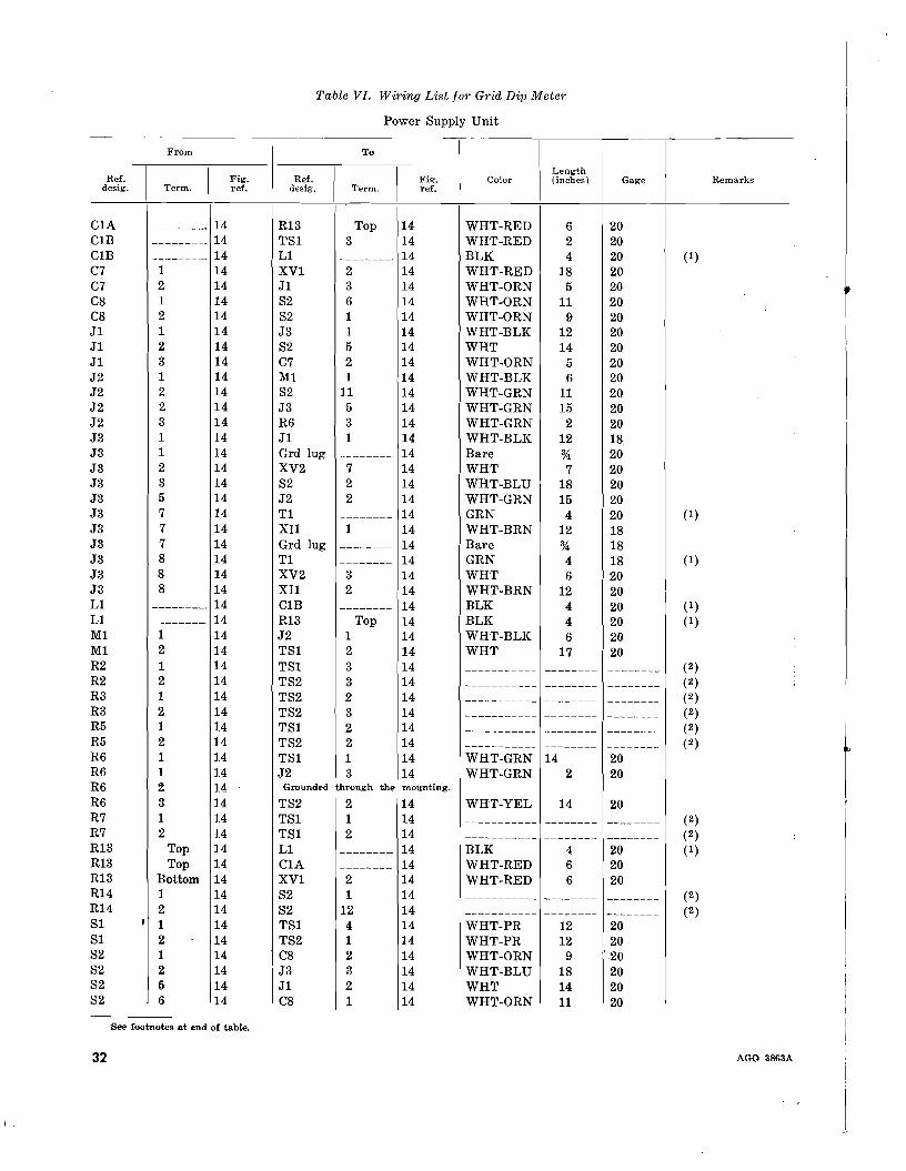
Table VI. Wiring List for Grid Dip Meter
Power Supply Unit
From To
I I I ILength
Ref. Fig. Ref. Fig-. Color (inches) Gagedesig. Term. ref. dESig. Term. ref.
C1A -------_. 14 R13 Top 14 WHT-RED 6 20C1B -------_. 14 TS1 3 14 WHT-RED 2 20ClB --------. 14 L1 _._-----_. 14 BLK 4 20C7 1 14 XV1 2 14 WHT-RED 18 20C7 2 14 J1 3 14 WHT-ORN 5 20C8 1 14 S2 6 14 WHT-ORN 11 20C8 2 14 S2 1 14 WHT-ORN 9 20J1 1 14 J3 1 14 WHT-BLK 12 20J1 2 14 S2 5 14 WHT 14 20J1 3 14 C7 2 14 WHT-ORN 5 20J2 1 14 M1 1 14 WHT-BLK 6 20J2 2 14 S2 11 14 WHT-GRN 11 20J2 2 14 J3 5 14 WHT-GRN 15 20J2 3 14 R6 3 14 WHT-GRN 2 20J3 1 14 J1 1 14 WHT-BLK 12 18J3 1 14 Grd lug ._~-----_. 14 Bare % 20J3 2 14 XV2 7 14 WHT 7 20J3 3 14 S2 2 14 WHT-BLU 18 20J3 5 14 J2 2 14 WHT-GRN 15 20J3 7 14 T1 -------- 14 GRN 4 20J3 7 14 XU 1 14 WHT-BRN 12 18J3 7 14 Grd lug -------- 14 Bare % 18J3 8 14 T1 -------- 14 GRN 4 18J3 8 14 XV2 3 14 WHT 6 20J3 8 14 XU 2 14 WHT-BRN 12 20L1 -------_. 14 ClB -------- 14 BLK 4 20L1 --------" 14 R13 Top 14 BLK 4 20M1 1 14 J2 1 14 WHT-BLK 6 20M1 2 14 TS1 2 14 WHT 17 20R2 1 14 TS1 3 14 ----------- -------- -----R2 2 14 TS2 3 14 ----------- -------- -----R3 1 14 TS2 2 14 ----------- -------- -----R3 2 14 TS2 3 14 ----------- -------- -----R5 1 14 TS1 2 14 ----------- -------- -----R5 2 14 TS2 2 14 ----------- -------- -----R6 1 14 TS1 1 14 WHT-GRN 14 20R6 1 14 J2 3 14 WHT-GRN 2 20R6 2 14 Grounded through the mounting.
R6 3 14 TS2 2 14 WHT-YEL 14 20R7 1 14 TS1 1 14
---~------- -------- -----R7 2 14 TS1 2 14 ----------- --------- -----R13 Top 14 L1 --------" 14 BLK 4 20R13 Top 14 C1A -------_. 14 WHT-RED 6 20R13 Bottom 14 XV1 2 14 WHT-RED 6 20R14 1 14 S2 1 14 ----------- -------_. -----R14 2 14 S2 12 14 ----------- -------- -----S1 , 1 14 TS1 4 14 WHT-PR 12 20S1 2 14 TS2 1 14 WHT-PR 12 20S2 1 14 C8 2 14 WHT-ORN 9 '20S2 2 14 J3 3 14 WHT-BLU 18 20S2 5 14 J1 2 14 WHT 14 20S2 6 14 C8 1 14 WHT-ORN 11 20
See footnotes at end of table.
32
Remarks
(1)
(1 )
(1)
(1)(1)
(2)(2)(2)(2)(2) I
(2)
tt
(2)I(2)
(1)
I!
(2) I
(2)
AGO 3863A

Table VI. Wiring List for Grid Dip Meter-Continued
Power Supply Unit--Continued--
ToI
I IColor Length
IRef. Fig. (inches) Gage Remarksdesig. Term. ref.
J2 2 14 WHT-GRN 11 20XV2 5 14 WHT-RED 18 20TS2 1 14 BLK 5 20 (1)TS2 4 14 BLK-RED 5 20 (1)J3 7 14 GRN 4 20 (1)J3 8 "!.4 GRN 4 20 (1)XVI 2 14 YEL-ORN 4 20XVI , 8 14 YEL-ORN 4 20 (1)XVI 4 14 RED 4 20 (1 )XVI 6 14 RED 4 20 (1)Grd lug
---~---_. 14 BLK-YEL 3 20 (1)Grd lug
-~-----_. 14 RED-YEL 3 20 (1)R7 1 14
----------~- -------- -------- (2)R6 1 14 WHT-GRN 14 20R7 1 14 ----------- -------- -------- (2)Ml 2 14 WHT 17 20R2 1 14 ----------- --------- -------- (2)ClB --------_. 14 WHT-RED 2 20 (2)81 1 14 WHT-PR 12 20WI ------- 14 BLK 6 ft. 1881 2 14 WHT-PR 12 20Tl
-----_._~ 14 BLK 5 20 (1)R3 1 14 ----------- -------- -------- (2)R5 2 14 ----------- -------- -------- (2)R6 3 14 WHT-YEL 14 20R3 2 14 ----------- -------- -------- (2)XV2 5 14 WHT-RED 3 20Tl -------- 14 BLK-RED 5 20WI -------- 14 WHT 6 ft. 18TSI 4 14 BLK 6.ft. 18T82 4 14 WHT 6 ft. 18J3 7 14 WHT-BRN 12 20J3 8 14 WHT-BRN 12 20C7 1 14 WHT-RED 18 20R13 Bottom 14 WHT-RED 6 20Tl -------- 14 YEL-ORN 4 20 (1)
Tl -------- 14 RED 4 20 (1)
Tl -------- 14 RED 4 20 (1)Tl -------- 14 YEL-ORN 4 20 (1)Grd lug -------- 14 Bare 1 20J3 8 14 WHT 6 2082 12 14 WHT-RED 18 20T82 3 14 WHT-RED 3 20J3 2 14 WHT 7 20
--_.
141414141414141414141414141414141414.1414141414141414141414141414141414141414141414141414
1222246823557
141122334411222
334
1112
1 Transformer T1 and reactor L1 are furnished with flexible leads extending from the unit.2 These resistors are mounted with their own axial leads.Note. For oscillator section wiring refer to paragraph 48e.
8282TlTlTlTlTlTlTlTl1'1TlTSITSIT81TSIT81T81T81T81T82T82T82TS2T82T82T82T82T82WIWIXUXUXVIXVIXVIXVIXVIXVIXV2XV2XV2XV2XV2
From
l::;:-I-=-I~--
AGO 3863A33
r
III/
/
J2 IrHONESl/
~::r-vll~I
IIII/
~- - - -RAPD411409
*
MICROFARADS, ANDNOTES, OHMS, MICRO OTEO
1. VAWES I~NlESS OTHERWISE N FROM REARHENRYS CHES" VIEWED
WAFER SWIT2. ALL
W2
T1
- - - t' diagram.chema wGrid dip meter, SFigure 20.
~"" ~'-- --- ---
IIIIII
~
//
\
J5
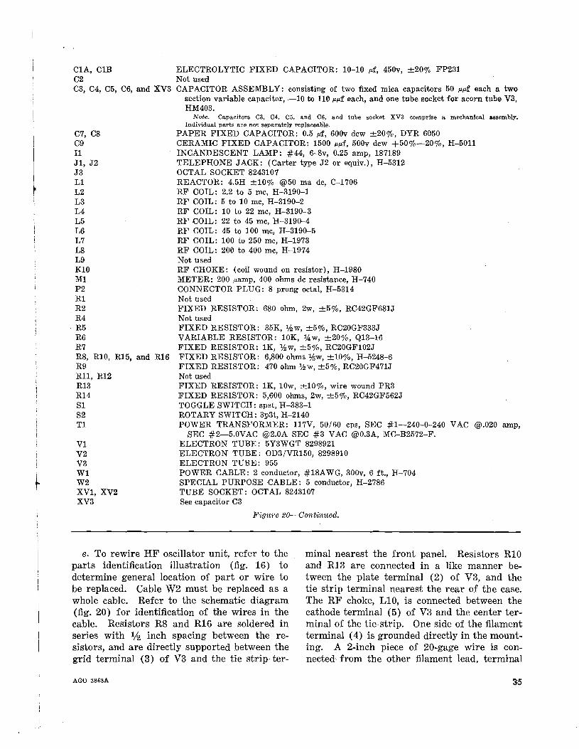
C1A, ClBC2C3, C4, C5, C6, and XV3
C7, C8C911J1, J2J3L1L2L3L4L5L6L7L8L9K10M1P2R1R2R4R5R6R7R8, R10, R15, and R16R9R11, R12R13R14S1S2T1
V1V2V3W1W2XV1, XV2XV3
ELECTROLYTIC FIXED CAPACITOR: 10-10 ",f, 450v, ±200/0 FP231Not usedCAPACITOR ASSEMBLY: consisting of two fixed mica capacitors 50 ",,,,f each a two
section variable capacitor, -10 to 110 ",,,,f each, and one tube socket for acorn tube V3,HM403.
Note. Capacitors C3, C4, C5, and C6, and tube socket XV3 comprise a mechanical assembly.Individual parts are not separately replaceable.
PAPER FIXED CAPACITOR: 0.5 ",f, 600v dcw ±200/0, DYR 6050CERAMIC FIXED CAPACITOR: 1500 ",,,,f, 500v dcw +500/0-200/0, H-5011INCANDESCENT LAMP: #44, 6-8v, 0.25 amp, 187189TELEPHONE JACK: (Carter type 32 or equiv.), H-5312OCTAL SOCKET 8243107REACTOR: 4.5H ±10% @50 rna dc, C-1706RF COIL: 2.2 to 5 mc, H-3190-1RF COIL: 5 to 10 mc, H-3190-2RF COIL: 10 to 22 mc, H-3190-3RF COIL: 22 to 45 mc, H-3190-4RF COIL: 45 to 100 mc, H-3190-5RF COIL: 100 to 250 mc, H-1973RF COIL: 200 to 400 mc, H-1974Not usedRF CHOKE: (coil wound on resistor), H-1980METER: 200 ",amp, 400 ohms dc resistance, H-740CONNECTOR PLUG: 8 prong octal, H-5314Not usedFIXED RESISTOR: 680 ohm, 2w, ±50/0, RC42GF681JNot usedFIXED RESISTOR: 35K, Ihw, ±50/0, RC20GF333JVARIABLE RESISTOR: 10K, 14w, ±200/0, Q13-16FIXED RESISTOR: 1K, Ihw, ±50/0, RC20GF102JFIXED RESISTOR: 6,800 ohms Ye;w, ±100/0, H-5248-6FIXED RESISTOR: 470 ohm Ihw, ±50/0, RC20GF471JNot usedFIXED RESISTOR: 1K, lOw, ±100/0, wire wound PR3FIXED RESISTOR: 5,600 ohms, 2w, ±50/0, RC42GF562JTOGGLE SWITCH: spst, H-383-1ROTARY SWITCH: 3p3t, H-2140POWER TRANSFORMER: 117V, 50/60 cps, SEC #1-240-0-240 VAC @.020 amp,
SEC #2-5.0VAC @2.0A SEC #3 VAC @0.3A, MC-B2572-F.ELECTRON TUBE: 5Y3WGT 8298921ELECTRON TUBE : OD3/VR150, 8298910ELECTRON TUBE: 955POWER CABLE: 2 conductor, #18AWG, 300v, 6 ft., H-704SPECIAL PURPOSE -CABLE: 5 conductor, H-2786TUBE SOCKET: OCTAL 8243107See capacitor C3
Figure 20-Continued.
e. To rewire HF oscillator unit, refer to theparts identification illustration (fig. 16) todetermine general location of part or wire tobe replaced. Cable W2 must be replaced as awhole cable. Refer to the schematic diagram(fig. 20) for identification of the wires in thecable. Resistors R8 and R16 are soldered inseries with 1J2 inch spacing between the resistors, and are directly supported between thegrid terminal (3) of V3 and the tie strip ter-
AGO 3863A
minal nearest the front panel. Resistors R10and R13 are connected in a like manner between the plate terminal (2) of V3, and thetie strip terminal nearest the rear of the case,The RF choke, L10, is connected between thecathode terminal (5) of V3 and the center terminal of the tie strip. One side of the filamentterminal (4) is grounded directly in the mounting. A 2-inch piece of 20-gage wire is connected from the other filament lead, terminal
(1) of V3 and the filament bypass capacitor.Resistor R9 mounts from the terminal near thetuning shaft and the ground lug as shown infigure 16.
Caution: All parts replaced in the oscillatorsection must be installed in the same relativepositions occupied by the original parts.
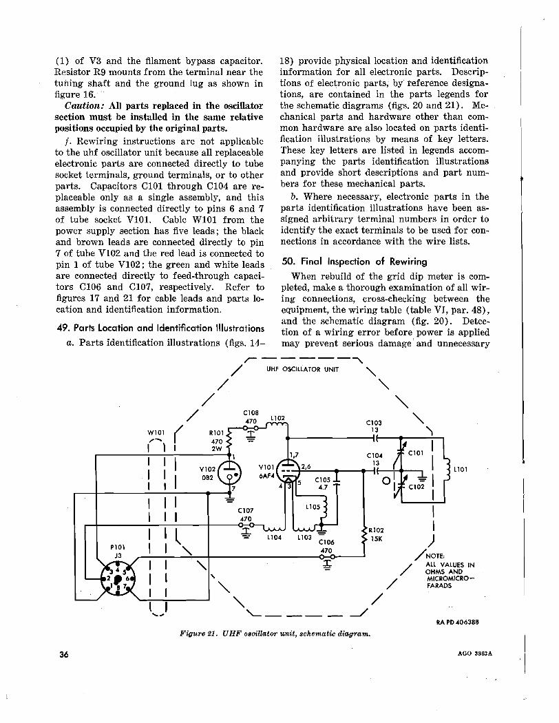
f. Rewiring instructions are not applicableto the uhf oscillator unit because all replaceableelectronic parts are connected directly to tubesocket terminals, ground terminals, or to otherparts. Capacitors C101 through C104 are r:eplaceable only as a single assembly, and thisassembly is connected directly to pins 6 and 7of tube socket V10l. Cable W101 from thepower supply section has five leads; the blackand brown leads are connected directly to pin7 of tube V102 and the red lead is connected topin 1 of tube V102; the green and white leadsare connected directly to feed-through capacitors C106 and C107, respectively. Refer tofigures 17 and 21 for cable leads and parts location and identification information.
49. Parts Location and Identification Illustrations
a. Parts identification illustrations (figs. 14-
18) provide physical location and identificationinformation for all electronic parts. Descriptions of electronic parts, by teference designations, are contained in the parts legends forthe schematic diagrams (figs. 20 and 21). Mechanical parts and hardware other than common hardware are also located on parts identification illustrations by means of key letters.These key letters are listed in legends accompanying the parts identification illustrationsand provide short descriptions and part numbers for these mechanical parts.
b. Where necessary, electronic parts in theparts identification illustrations have been assigned arbitrary terminal numbers in order toidentify the exact terminals to be used for connections in accordance with the wire lists.
50. Final Inspection of Rewiring
When rebuild of the grid dip meter is completed, make a thorough examination of all wir...ing connections, cross-checking between theequipment, the wiring table (table VI, par. 48),and the schematic diagram (fig. 20). Detection of a wiring error before power is appliedmay prevent serious damage' and unnecessary
36
,------""""\./ UHF OSCII.LATOR UNIT "-
/ "/ "-/ Cl08
"470 L102Cl03
W101 ( X.13 ),. .....
I1 I
I IC104
I13
IVl02 Ll01
I 082 II
I I - I
I ICl07 I470
II l -!- Rl02L104 L103 - )Cl06 15K
P101 I "- 470/NOTE:J3
I "- ;. / ALL VALUES IN
I , OHMS AND
"/
MICROMICRO-
IFARADS
"/
J...... '---- --./RA PD4063BB
Figure 21. UHF oscillator unit, schematic diagram.
AGO 3863A

C101, C102, C103,C104, XV101
C105C106, C107, C108L101L102L103, L104L105P101R101Rl02V101V102W101
CAPACITOR ASSEMBLY: consisting of two fixed mica capacitors 13 f.Lf.Lf each, a twosection variable capacitor, and one tube socket for V101 (6AF4) H-4614.Note. Capacitors CIOI, CI02, CI03, and CI04, and tube socket XYlOl comprise a mechanical assembly.
Individual parts are not separately replaceable.
CERAMIC FIXED CAPACITOR: 4.7 f.Lflf, 500v dew, ±100/0, H-5372CERAMIC FIXED CAPACITOR: 470 f.Lf.Lf, 500v dew, ±200/0, H-5373RF COIL: H-4635RF COIL: H-4639RF COIL: H-4636RF COIL: H-4638CONNECTOR PLUG: 8 prong octal, H-5314FIXED RESISTOR: 470 ohm, 2w, ±100/0, RC42GF471KFIXED RESISTOR: 470 ohm, 1h w, ±100/0, RC20GF471KELECTRON TUBE: 6AF4ELECTRON TUBE: OB2, 7599321SPECIAL PURPOSE CABLE: H-886
Figure 21-Continued.
. I
rework. When all Wlrmg has been doublechecked and proven to be satisfactory, installthe tubes in their sockets except for the rectifier tube. Measure the resistance from thecathode pin of the rectifier socket to chassisground. The resistance should be approximately 280K. A deviation of more than ±20percent indicates a defect in the B+ circuitthat must be corrected before power is applied.
AGO 8863A
Apply power with the rectifier tube removedfrom socket and observe that filaments ofother tubes glow. If no malfunctions are apparent, install the rectifier tube and examineall parts of the grid dip meter for evidence ofshort circuits. When this inspection is completed, proceed with the final inspection(chapter 9).
37

CHAPTER 9FINAL INSPECTION AND R'EPAIR STANDARDS
51. General
Final inspection is an acceptance inspectionperformed after repair and rebuild operationshave been completed to insure that the materielis acceptable according to established standards. Final inspection of the grid dip meterconsists of a visual inspection and an operational check.
52. Visual Inspection
.Visually inspect the grid dip meter for completeness of parts. Use the illustrations infigures 14, 15, 16, and 17 for this purpose. Inspect power supply unit and oscillator unit forphysical defects or damage.
53. Soldering
Most electrical connections must be solderedto insure that a good electrical bond is made.The oxidation or corrosion that takes place inan unsoldered or poorly soldered joint will re-
38
suIt in intermittent or faulty operation of thegrid dip meter. Connections must be mechanically secure and contact surfaces clean andbright before solder is applied.
a. When a joint has been soldered, chip orscrape any excess deposit of flux from the joint.
b. Inspect the connection for evidence of coldsoldering. See that an excessive amount ofsolder has not been used and that the solder isnot touching an adjacent terminal or conducting surface of some other part.
c. If the joints have been previol,lsly tropicalized, apply tropicalization varnish according toinstructions given in TB ORD 350.
54. Operational Check
Conduct a complete operational check (tableV, par. 24) after the visual inspection to becertain the grid dip meter meets all electronicspecifications.
AGO 3863A
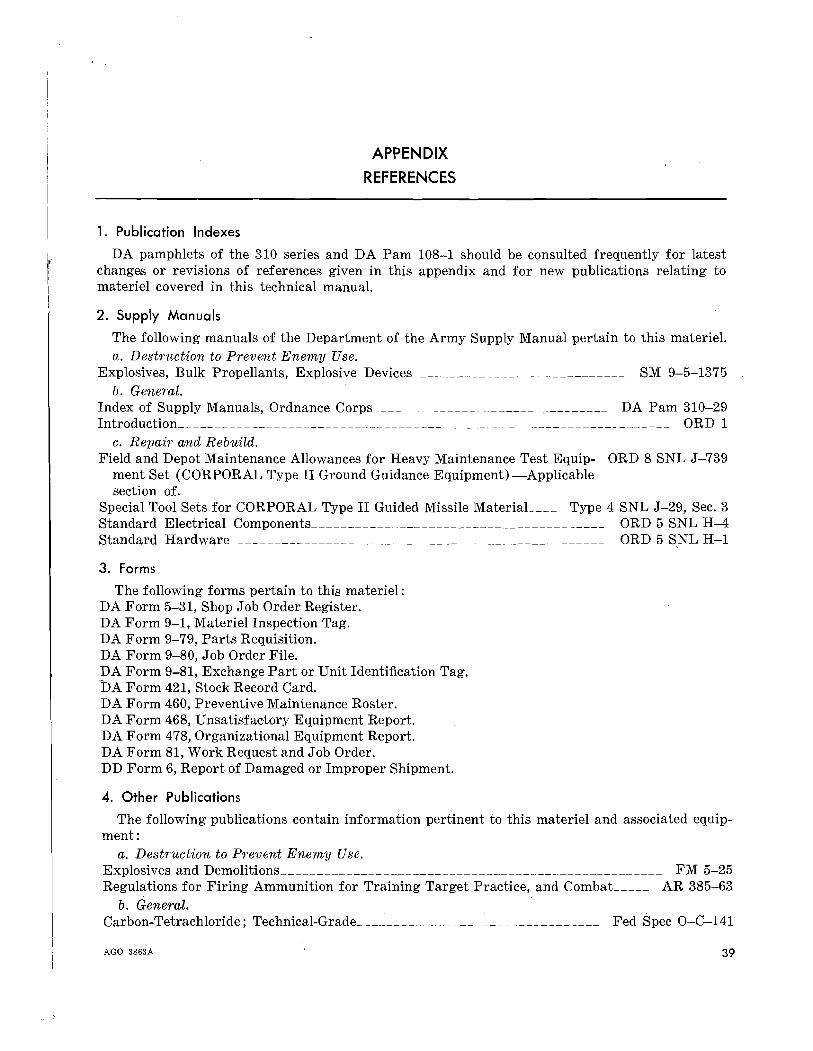
APPENDIX
REFERENCES
1. Publication Indexes
DA pamphlets of the 310 series and DA Pam 108-1 should be consulted frequently for latestchanges or revisions of references given in this appendix and for new publications relating tomateriel covered in this technical manual.
2. Supply Manuals
The following manuals of the Department of the Army Supply Manual pertain to this materiel.a. Destruction to PTevent Enemy Use.
Explosives, Bulk Propellants, Explosive Devices_______________________________ SM 9-5-1375b. GenemL
Index of Supply Manuals, Ordnance Corps_________________________________ DA Pam 310-29Introduction____________________________________________________________________ ORD 1
c. Repair and Rebuild.Field and Depot Maintenance Allowances for Heavy Maintenance Test Equip- ORD 8 SNL J-739
ment Set (CORPORAL Type II Ground Guidance Equipment)-Applicablesection of.
Special Tool Sets for CORPORAL Type II Guided Missile MateriaL___ Type 4 SNL J-29, Sec. 3Standard Electrical Components________________________________________ ORD 5 SNL H-4Standard Hardware ORD 5 SNL H-1
3. Forms
The following forms pertain to this materiel:DA Form 5-31, Shop Job Order Register.DA Form 9-1, Materiel Inspection Tag.DA Form 9-79, Parts Requisition.DA Form 9-80, Job Order File.DA Form 9-81, Exchange Part or Unit Identification Tag.DA Form 421, Stock Record Card.DA Form 460, Preventive Maintenance Roster.DA Form 468, Unsatisfactory Equipment Report.DA Form 478, Organizational Equipment Report.DA Form 81, Work Request and Job Order.DD Form 6, Report of Damaged or Improper Shipment.
4. Other Publications
The following publications contain information pertinent to this materiel and associated equipment:
a. Destruction to Prevent Enemy Use.Explosives and Demolitions_____________________________________________________ FM 5-25Regulations for Firing Ammunition for Training Target Practice, and CombaL____ AR 385-63
b. General.Carbon-Tetrachloride; Technical-Grade_________________________________ Fed Spec O-C-141
AGO 3863A 39
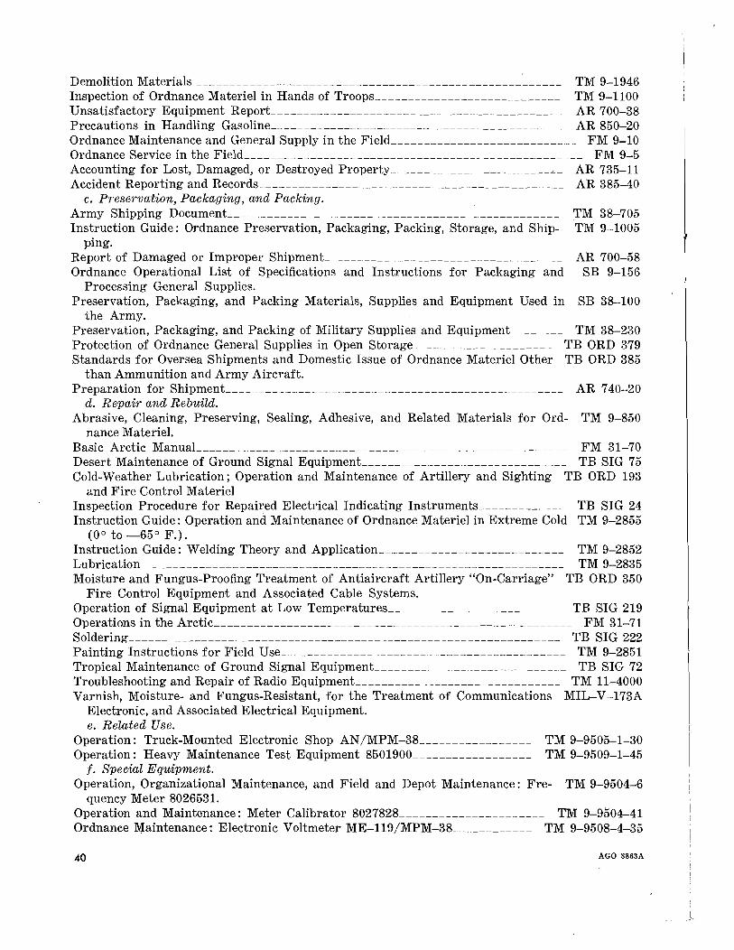
Demolition Materials TM 9-1946Inspection of Ordnance Materiel in Hands of Troops____________________________ TM 9-1100Unsatisfactory Equipment Report____________________________________________ AR 700-38Precautions in Handling Gasoline_____________________________________________ AR 850-20Ordnance Maintenance and General Supply in the Field____________________________ FM 9-10Ordnance Service in the Field___________________________________________________ FM 9-5Accounting for Lost, Damaged, or Destroyed Property -"-_ AR 735-11Accident Reporting and Records______________________________________________ AR 385-40
c. Preservation, Packaging, and Packing.Army Shipping DocumenL_________________________________________________ TM 38-705Instruction Guide: Ordnance Preservation, Packaging, Packing, Storage, and Ship- TM 9-1005
ping.Report of Damaged or Improper ShipmenL___________________________________ AR 700-58Ordnance Operational List of Specifications and Instructions for Packaging and SB 9-156
Processing General Supplies.Preservation, Packaging, and Packing Materials, Supplies and Equipment Used in SB 38-100
the Army.Preservation, Packaging, and Packing of Military Supplies and EquipmenL_______ TM 38-230Protection of Ordnance General Supplies in Open Storage_____________________ TB ORD 379Standards for Oversea Shipments and Domestic Issue of Ordnance Materiel Other TB ORD 385
than Ammunition and Army Aircraft.Preparation for ShipmenL___________________________________________________ AR 740-20
d. Repair and Rebuild.Abrasive, Cleaning, Preserving, Sealing, Adhesive, and Related Materials for Ord- TM 9-850
nance Materiel.Basic Arctic ManuaL_______________________________________________________ FM 31-70Desert Maintenance of Ground Signal EquipmenL______________________________ TB SIG 75Cold-Weather Lubrication; Operation and Maintenance of Artillery and Sighting TB ORD 193
and Fire Control MaterielInspection Procedure for Repaired Electrical Indicating Instruments_____________ TB SIG 24Instruction Guide: Operation and Maintenance of Ordnance Materiel in Extreme Cold TM 9-2855
(00 to _65 0 F.).Instruction Guide: Welding Theory and Application____________________________ TM 9-2852Lubrication TM 9-2835Moisture and Fungus-Proofing Treatment of Antiaircraft Artillery "On-Carriage" TB ORD 350
Fire Control Equipment and Associated Cable Systems.Operation of Signal Equipment at Low Temperatures__________________________ TB SIG 219Operations in the Arctic______________________________________________________ FM 31-71Soldering_________________________________________________________________ TB SIG 222Painting Instructions for Field Use -,-______________ TM 9-2851Tropical Ma.intenance of Ground Signal EquipmenL____________________________ TB SIG 72Troubleshooting and Repair of Radio EquipmenL______________________________ TM 11-4000Varnish, Moisture- and Fungus-Resistant, for the Treatment of Communications MIL-V-173A
Electronic, and Associated Electrical Equipment.e. Related Use.
Operation: Truck-Mounted Electronic Shop AN/MPM-38_________________ TM 9-9505-1-30Operation: Heavy Maintenance Test Equipment 8501900__________________ TM 9-9509-1-45
f. Special Equipment.Operation, Organizational Maintenance, and Field and Depot Maintenance: Fre- TM 9-9504-6
quency Meter 8026531.Operation and Maintenance: Meter Calibrator 8027828______________________ TM 9-9504-41Ordnance Maintenance: Electronic Voltmeter ME-119/MPM-38____________ TM 9-9508-4-35
40 AGO 3863A
!
J

INDEX
ParagraphsAlinement and calibration ~______ 25Application of grid dip meteL__________ 5Assembly:
Oscillator and oscillator case 39,42Power supply_____________________ 36
Authorized forms. (See Forms, records,and reports.)
Description -_ __ 5Difference among models_______________ 6Disassembly:
Oscillator and oscillator case 37,40Power supply 34
Dressing wire__________________________ 32
Soldering_____________________________ 29 23Special tools and equipment (table IV) 15 11Symbols and designations_______________ 4 4
Repair and maintenance 26-50 23-36Report of unsatisfactory equipment or
materiels. (See Forms, records, andreports.)
Electronic data (table II) _
Field and depot maintenance allocation _Field report of accidents. (See Forms,
records, and reports.)Forms, records and reports _
Handling of disassembled parts _
8
2
3
33
Pages
224
29,3029
45
29,302924
5
2
2
27
Paragraphs
Maintenance-ContinuedAssembly of power supply__________ 36Disassembly of oscillator and oscil- 37
lator case.Disassembly of power supply________ 34Lubrication_______________________ 43Operational check and trouble- 24
shooting.
Operational check. (See Maintenance.)
Physical data (table 1) 7
Pages
2929
293016
5
Inspection:Final inspection and repair 51-54
standards.Final inspection of rewiring________ 50Inspection of general components 20-21
of the grid dip meter.In-process________________________ 18Inspection of electrical components 21
of the grid dip meter.Inspection of mechanical components 20
of the grid dip meter.
Lubrication___________ 43
Maintenance:Alinement and calibration__________ 25Assembly of oscillator and oscillator 39
case.
AGO 3863A
38
3615
1415
15
30
2229
Theory:Power supply 10, 11Oscillator section lO, 11
Tropicalization_______________ 29Troubleshooting (table V) 24Tube complement (table III) 8Tables:
Electronic data (table II) 8Operational check and troubleshoot- 24
ing of grid dip meter (table V).Physical data (table I) 7
Special tools and equipment (table 15IV).
Tube complement (table III) 8Wiring list for grid dip meter (table 48
VI).
6,76,7
23165
516
511
531
41
[413.6 (19 Jan 59)]
By Order of Wilber M. Brucker, Secretary of the Army:
Official:R. V. LEE,
Major General, United States Army,The Adjutant General.
MAXWELL D. TAYLOR,General, United States Army,
Chief of Staff.
Distribution:
Active Army:DCSLOG (1)Tech Stf DA (1) except
CofOrd (17)Ord Bd (2)USA Arty Bd (3)USA Armor Bd (3)USA Inf Bd (3)USA AD Bd (3)USA Abn & Elct Bd (3)USA Avn Bd (3)USA Arctic Test Bd (3)USCONARC (3)US ARADCOM (2)US ARADCOM Rgn (2)OS MajComd (5) except
USARCARIB (None)Log Comd (3)MDW (1)Armies (3)
NG: State AG (3).
USAR: None.
For explanation of abbreviations used, see AR 320-50.
42
USAAMC (2)USA AD Cen (2)US ARADSCH (5)USAOGMS (70)Ord Sec, Gen Dep (10)Ord Dep (10)Ord Ammo Comd (1)USAREUR CommZ (6)Ord PG (10)Ord Arsenals (10) except
Raritan Arsenal (100)Army Rkt GM Agcy (30)Fld Comd, AFSWP (16)MAAG (West Germany) (2)MAAG (United Kingdom) (2)Units org under fol TOE:
9-227 (5)9-500 (5)9-510 (3)
{t u. S. GOVERNMENT PRINTING OFFICE: 1959-480507
AGO 3863A
j

, .~
~
r an..~-ICDCD...CCI~CCICCI
, =I~. .....I-.....:::IE...........~
'.-. >-~Ii: ....::cc:.a.....:::IE
f,'
( .