deploy a high-performance standalone oracle database · pdf filedeploy a high-performance...
TRANSCRIPT

White Paper
© 2017 Cisco and/or its affiliates. All rights reserved. This document is Cisco Public. Page 1 of 25
Deploy a High-Performance Standalone Oracle Database Solution
Oracle Database 12c R2 on Cisco UCS C220 M4 Rack Server with HGST Ultrastar
PCIe Solid-State Drive
May 2017

© 2017 Cisco and/or its affiliates. All rights reserved. This document is Cisco Public. Page 2 of 25
Contents
Introduction Objectives Audience Purpose of This Document
Benefits of the Solution
Solution Overview Cisco Unified Computing System Cisco UCS C220 M4 Rack Server HGST Ultrastar PCIe SSD
Solution Design Cisco UCS C220 M4 Server Configuration HGST Ultrastar SN100 and SN150 SSD Configuration Oracle Grid Infrastructure and Database 12c R2 Configuration
Performance and Failover Analysis FIO Results Swingbench Configuration Swingbench Results Performance Impact of Failure of One NVMe Device
Conclusion
For More Information

© 2017 Cisco and/or its affiliates. All rights reserved. This document is Cisco Public. Page 3 of 25
Introduction
Today, data is being stored, managed, and transmitted across a broad mix of IT computing infrastructure. Unique
requirements, priorities, and challenges create continuous pressure for greater performance, reliability,
manageability, and affordability. High-performance storage is essential to make applications run faster, achieve
quicker response times, and analyze more data to extract meaningful information more quickly.
As storage moves closer to the server, new opportunities for data center efficiency are arising. The Cisco Unified
Computing System™
(Cisco UCS®) is a next-generation data center platform that unites computing, networking,
storage, and virtualization resources in a cohesive system designed to reduce total cost of ownership (TCO) and
increase business agility. Ultra-low-latency nonvolatile memory express (NVMe) storage fully integrated into the
Cisco UCS architecture enables servers to provide increased storage reliability and performance compared to
spinning media.
Bringing storage inside the server on a high-performance NVMe tier can also reduce application licensing costs,
making local flash storage a powerful solution for delivering more capabilities on a smaller budget. And all these
benefits are more fully optimized on Cisco UCS than on any other server platform.
Objectives
This document provides a reference architecture that illustrates the benefits of using the Cisco UCS C220 M4 Rack
Server with HGST NVMe solid-state drives (SSDs) for a high-performance transactional standalone Oracle
Database 12c Release 2 (R2) system. The architecture provides a robust, resilient, and efficient infrastructure
solution that can meet the demanding needs of businesses today.
Audience
This document is intended for solution architects, sales engineers, field engineers, and design consultants involved
in planning, designing, and deploying a standalone Oracle Database solution on Cisco UCS and HGST NVMe SSD
infrastructure. This document assumes that the reader has an architecture-level understanding of the base
configuration and implementation of Oracle Database, Cisco UCS, and HGST NVMe-compliant PCI Express
(PCIe) SSDs.
Purpose of This Document
This document discusses how customers can achieve high I/O throughput with very low storage access latency
when using Cisco UCS C-Series Rack Servers with HGST Ultrastar NVMe storage for their enterprise-class
standalone Oracle Database deployments. Cisco UCS rack servers use direct-connect technology, allowing the
use of Cisco UCS service profiles on rack servers managed by Cisco UCS and providing the highest level of
uptime possible by facilitating migration in the event of component or server failure.
This document also demonstrates the scalability and performance of the solution by running Swingbench on an
online transaction processing (OLTP) database as a benchmark. The Swingbench tool was used to populate the
database and generate the I/O workload for this solution. The tests were run with varying numbers of users and a
variety of read and update workload characteristics on the standalone Oracle Database 12c R2 on the Cisco UCS
C220 M4 Rack Server.

© 2017 Cisco and/or its affiliates. All rights reserved. This document is Cisco Public. Page 4 of 25
The testing reported in this document has the following purposes:
● To evaluate the maximum performance of a single instance of Oracle Database 12c R2 on Cisco UCS
C220 M4 Rack Servers with HGST Ultrastar NVMe SSDs
● To illustrate how a single-instance Oracle Database with Cisco UCS and HGST Ultrastar NVMe SSD can
be used as an enterprise-class solution to implement reliable and cost-effective Oracle Database solutions
Benefits of the Solution
NVMe storage can be used to eliminate the need for SANs and network-attached storage (NAS) or to augment
existing shared-array infrastructure. Cisco UCS implements local storage differently for a uniquely powerful
experience. The Cisco UCS platform uses an advanced cooling methodology and zero-oversubscription CPU
mapping to provide a high level of efficiency as well as best-in-class, consistent performance. Teams can manage
hundreds of devices as easily as one with the Cisco® Integrated Management Controller (IMC) or Cisco UCS
Manager. Customers can also choose the amount of storage necessary to meet their application needs: from 400
GB all the way up to 30 TB (for example, for a 2-rack-unit [2RU] server).
Cisco UCS rack servers with the HGST Ultrastar NVMe SSD solution offer following benefits:
● Easily deploy and scale the solution.
● Achieve a high number of I/O operations per seconds (IOPS) with very low latency.
● Reduce business disruption and increase Oracle Database efficiency by deploying a pretested and
validated solution.
● Get a faster response at a lower cost.
● Gain flexibility, increased performance, and compatibility with industry standards.
● Deploy the most efficient methodology for handling thermal control for local storage.
● Through deep integration with Cisco UCS Manager and IMC, manage device performance status, flash-
memory life-left status, and firmware.

© 2017 Cisco and/or its affiliates. All rights reserved. This document is Cisco Public. Page 5 of 25
Solution Overview
The reference architecture discussed in this document uses the Cisco UCS platform, with Cisco UCS 6332-16UP
Fabric Interconnects for system management, Cisco Nexus® 9372PX-E Switches, the Cisco UCS C220 M4 Rack
Server, and HGST Ultrastar NVMe-compliant PCIe SSDs with standalone Oracle Database 12c R2 (Figure 1). This
architecture is specifically designed for high performance on a single physical server for standalone Oracle
Database workloads.
Figure 1. Solution Architecture
LAN
vPC Peer Link 1
Cluster Link
Cisco Nexus 9372PX-E
10-Gbps Uplink Traffic
10-Gbps Network Traffic
Cisco UCS C220 M4 Rack Server
CISCO UCS-FI-6332-16UP
ENV
LS
STS
BCN
1
2
3
4
L1 L2
17 18 19 20 21 22 23 24 25 26 27 28 29 30 31 32 33 34 39 4037 3835 361 2 3 4 5 6 7 8 9 10 11 12 13 14 15 16
CISCO NEXUS N9K-C9372TX
53 5451 5249 501 2 3 4 5 6 7 8 9 10 11 12 13 14 15 16 17 18 19 20 21 22 23 24 25 26 27 28 29 30 31 32 33 34 35 36 37 38 39 40 41 42 43 44 45 46 47 48
Cisco UCS 6332-16UP
CISCO NEXUS N9K-C9372TX
53 5451 5249 501 2 3 4 5 6 7 8 9 10 11 12 13 14 15 16 17 18 19 20 21 22 23 24 25 26 27 28 29 30 31 32 33 34 35 36 37 38 39 40 41 42 43 44 45 46 47 48
CISCO UCS-FI-6332-16UP
ENV
LS
STS
BCN
1
2
3
4
L1 L2
17 18 19 20 21 22 23 24 25 26 27 28 29 30 31 32 33 34 39 4037 3835 361 2 3 4 5 6 7 8 9 10 11 12 13 14 15 16
4
1
5
2
6
3
7 8 UCSC220 M4
Intel
Inside
XEON
Console!
Ultrastar SN100 NVMeUltrastar SN100 NVMe Ultrastar SN150 NVMeUltrastar SN150 NVMe
Cisco Nexus 9372PX-E
Cisco UCS 6332-16UP
Table 1 shows the hardware and software used for this solution.
Table 1. Hardware and Software Used in the Solution
Component Model Software Version
Management 2 Cisco UCS 6332-16UP Fabric Interconnects Cisco UCS Manager Release 3.1 (2b)
Computing 1 Cisco UCS C220 M4 Rack Server Cisco UCS Manager Release 3.1 (2b)
Network 2 Cisco Nexus 9372PX-E Switches with Cisco NX-OS Software Release 6.1(2) I2 (2a)
Storage ● 2 HGST Ultrastar SN150 (3.8 TB) (UCSC-F-H38001)
● 2 HGST Ultrastar SN100 (3.8 TB) (UCS-PCI25-38001)
Version KMCCP105
Software ● Cisco UCS Manager Release 3.1 (2b)
● Oracle Linux Server 7.2 (64-bit) Linux 3.8.13-98.7.1.el7uek.x86_64

© 2017 Cisco and/or its affiliates. All rights reserved. This document is Cisco Public. Page 6 of 25
Component Model Software Version
● Oracle Database 12c R2 for Linux x86-64 Release 12.2.0.1.0
● Oracle Database 12c R2 Grid Infrastructure for Linux x86-64 Release 12.2.0.1.0
● Oracle Database 12c R2 Client for Linux x86-64 Release 12.2.0.1.0
● HGST Device Manager (HDM) Release 3.2
● Oracle Swingbench Release 2.5.971
Cisco Unified Computing System
Cisco UCS is a next-generation solution for blade and rack server computing. The system integrates a low-latency,
lossless 40 Gigabit Ethernet unified network fabric with enterprise-class, x86-architecture servers. The system is
an integrated, scalable, multichassis platform in which all resources participate in a unified management domain.
Cisco UCS accelerates the delivery of new services simply, reliably, and securely through end-to-end provisioning
and migration support for both virtualized and nonvirtualized systems. This high-performance, next-generation
server system provides a data center with a high degree of workload agility and scalability.
Cisco UCS is designed to deliver:
● Reduced TCO and increased business agility
● Increased IT staff productivity through just-in-time provisioning and mobility support
● A cohesive, integrated system that unifies the technology at the data center, with the system managed,
serviced, and tested as a whole
● Scalability through a design for hundreds of discrete servers and thousands of virtual machines and the
capability to scale I/O bandwidth to match demand
● Industry standards supported by a partner ecosystem of industry leaders
Cisco UCS offers wide range of storage options to meet customer application needs: from 800 GB to up to 55 TB,
as shown in Figure 2.
Figure 2. Cisco UCS PCIe and NVMe Storage Options
Cisco UCS C220 M4 Rack Server
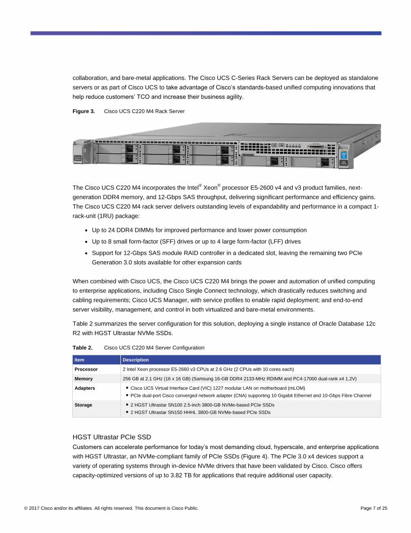
The Cisco UCS C220 M4 Rack Server (Figure 3) is the most versatile general-purpose enterprise infrastructure
and application server in the industry. It is a high-density 2-socket enterprise-class rack server that delivers
industry-leading performance and efficiency for a wide range of enterprise workloads, including virtualization,
© 2017 Cisco and/or its affiliates. All rights reserved. This document is Cisco Public. Page 7 of 25
collaboration, and bare-metal applications. The Cisco UCS C-Series Rack Servers can be deployed as standalone
servers or as part of Cisco UCS to take advantage of Cisco’s standards-based unified computing innovations that
help reduce customers’ TCO and increase their business agility.
Figure 3. Cisco UCS C220 M4 Rack Server
The Cisco UCS C220 M4 incorporates the Intel® Xeon
® processor E5-2600 v4 and v3 product families, next-
generation DDR4 memory, and 12-Gbps SAS throughput, delivering significant performance and efficiency gains.
The Cisco UCS C220 M4 rack server delivers outstanding levels of expandability and performance in a compact 1-
rack-unit (1RU) package:
● Up to 24 DDR4 DIMMs for improved performance and lower power consumption
● Up to 8 small form-factor (SFF) drives or up to 4 large form-factor (LFF) drives
● Support for 12-Gbps SAS module RAID controller in a dedicated slot, leaving the remaining two PCIe
Generation 3.0 slots available for other expansion cards
When combined with Cisco UCS, the Cisco UCS C220 M4 brings the power and automation of unified computing
to enterprise applications, including Cisco Single Connect technology, which drastically reduces switching and
cabling requirements; Cisco UCS Manager, with service profiles to enable rapid deployment; and end-to-end
server visibility, management, and control in both virtualized and bare-metal environments.
Table 2 summarizes the server configuration for this solution, deploying a single instance of Oracle Database 12c
R2 with HGST Ultrastar NVMe SSDs.
Table 2. Cisco UCS C220 M4 Server Configuration
Item Description
Processor 2 Intel Xeon processor E5-2660 v3 CPUs at 2.6 GHz (2 CPUs with 10 cores each)
Memory 256 GB at 2.1 GHz (16 x 16 GB) (Samsung 16-GB DDR4 2133-MHz RDIMM and PC4-17000 dual-rank x4 1.2V)
Adapters ● Cisco UCS Virtual Interface Card (VIC) 1227 modular LAN on motherboard (mLOM)
● PCIe dual-port Cisco converged network adapter (CNA) supporting 10 Gigabit Ethernet and 10-Gbps Fibre Channel
Storage ● 2 HGST Ultrastar SN100 2.5-inch 3800-GB NVMe-based PCIe SSDs
● 2 HGST Ultrastar SN150 HHHL 3800-GB NVMe-based PCIe SSDs
HGST Ultrastar PCIe SSD
Customers can accelerate performance for today’s most demanding cloud, hyperscale, and enterprise applications
with HGST Ultrastar, an NVMe-compliant family of PCIe SSDs (Figure 4). The PCIe 3.0 x4 devices support a
variety of operating systems through in-device NVMe drivers that have been validated by Cisco. Cisco offers
capacity-optimized versions of up to 3.82 TB for applications that require additional user capacity.

© 2017 Cisco and/or its affiliates. All rights reserved. This document is Cisco Public. Page 8 of 25
Figure 4. HGST Ultrastar PCIe SSD
Well suited for mission-critical data center workloads, including scale-out databases powering today’s largest
online and cloud services, the Ultrastar enables businesses to achieve a better return on their data center
infrastructure investments with gains such as more database transactions per second (TPS), lower access latency,
and easier application scaling. The Ultrastar delivers exceptional value by reducing the cost of deploying and
managing high-performance storage in scale-out and cloud environments. The Ultrastar uses standard NVMe
drivers to take advantage of the benefits of PCIe without requiring vendor-unique drivers. This approach makes the
Ultrastar as easy to deploy as traditional storage devices while offering top performance.
The Ultrastar has following main features:
● High density: Up to 3.8 TB in both compact form factors
● High performance: Up to 310,000 mixed sustained random IOPS
● High serviceability: Hot-swappable SFF drive
● NVMe compliance: Support for standard NVMe drivers
PCIe SSDs offer several advantages over storage arrays:
● Performance: The biggest benefit of PCIe SSDs is increased performance. The PCIe interface has low
latency for data transfer, and it bypasses any SAN when storing or retrieving data. It thus provides the
fastest way to access data. It delivers microsecond-level latency, in contrast to the millisecond-level latency
delivered by traditional SAN-based storage.
● Space savings: PCIe SSDs are compact and fit into the PCIe slot of a server. They eliminate the need for
rack space, cooling, and power for storage servers.
● Energy savings: Server-attached PCIe SSDs eliminate the need for additional storage servers, hence
saving on power and cooling. Traditional storage solutions for high-throughput, low-latency, and high-IOPS
workloads need hundreds of hard disk drives (HDDs) and Fibre Channel controllers and significant amounts
of power and cooling.

© 2017 Cisco and/or its affiliates. All rights reserved. This document is Cisco Public. Page 9 of 25
Solution Design
The setup and configuration of the Cisco UCS 6332-16UP Fabric Interconnects, Cisco UCS C220 M4 Rack Server,
and Oracle Database 12c R2 are beyond scope of this document. This section presents the high-level steps for
configuring the system.
Cisco UCS C220 M4 Server Configuration
This section describes the high-level steps for configuring Cisco UCS fabric interconnects and the Cisco UCS
C220 M4 server to deploy a standalone Oracle Database 12c R2.
1. Configure fabric interconnects for a cluster setup.
a. Perform initial setup of fabric interconnects A and B.
b. Open a web browser and navigate to the Cisco UCS fabric interconnect cluster address.
c. Launch Cisco UCS Manager.
2. Configure fabric interconnects server ports to discover the Cisco UCS C220 M4 server.
3. Upgrade Cisco UCS Manager Software to Release 3.1 (2b).
4. Create a block of IP address for keyboard, video, and mouse (KVM) access.
5. Configure the VLAN on Cisco UCS Manager.
6. Configure Ethernet LAN uplink ports on fabric interconnects A and B.
7. Configure unique user ID (UUID), IP address, and MAC address pools.
a. Create the UUID pool.
b. Create IP and MAC address pools in Cisco UCS Manager.
8. Configure virtual network interface card (vNIC) templates.
9. Configure Ethernet uplink port channels.
10. Create server boot policy for local boot.
11. Configure and create the service profile template.
12. Configure and create the service profile from the service profile template.
13. Assign the service profile to the server.
14. Launch the KVM console on the desired server, enable virtual media, map the Oracle Linux 7.2 ISO image,
and reset the server.
During the server boot operation, the server will detect the virtual media connected as the Oracle Linux CD. It
should launch the Oracle Linux installer.
The Cisco UCS C220 M4 server was configured with Oracle Linux 7.2, and all the prerequisites for installing
standalone Oracle Database 12c R2 have been completed.
HGST Ultrastar SN100 and SN150 SSD Configuration
This solution uses two HGST SN100 3800-GB NVMe SSDs and two HGST SN150 3800-GB NVMe PCIe SSDs.
The HDM is designed to efficiently assist in the administration of HGST SSD devices. HDM Release 3.2 is installed
to configure Ultrastar NVMe-compliant PCIe SSDs.
Refer the following link for more information:
http://www.hgst.com/sites/default/files/resources/HGST-Device-Manager-3.2-UserGuide.pdf.

© 2017 Cisco and/or its affiliates. All rights reserved. This document is Cisco Public. Page 10 of 25
Note: We strongly recommend that you use the HDM utility to resize and configure Ultrastar NVMe cards if you
plan to resize and configure the HGST NVMe SSD. For your environment, verify the HDM release to use with your
Cisco UCS Manager release. To download the HDM for a given Cisco UCS Manager release, refer to the following
link:
https://software.cisco.com/download/release.html?mdfid=283862063&flowid=25886&softwareid=283850975&os=Li
nux&release=2.0(9a)&relind=AVAILABLE&rellifecycle=&reltype=latest.
Follow these steps to configure HGST NVMe devices:
1. Log on to the system using root privileges and install HDM 3.2 (RPM packet manager [RPM]) to run the
HDM utility.
[root@oradbapp2 u01]# rpm -ivh hdm-core-3.3.0-8.cb-x86_64.rpm
Preparing... ################################# [100%]
Updating / installing...
1:hdm-core-3.3.0-8.cb ################################# [100%]
2. Scan and verify all the NVMe devices on the server by using hdm scan commands.
[root@oradbapp2 ~]# hdm scan
3. After the HDM package is installed, verify all NVMe devices detected on the OS native path at /dev/*.
[root@oradbapp2 ~]# ls -al /dev/nvme*
crw ------------ 1 root root 248, 0 Mar 23 15:17 nvme0
brw-rw ------- 1 root disk 259, 9 Mar 23 15:17 nvme0n1
crw ------------ 1 root root 248, 1 Mar 23 15:17 nvme1
brw-rw ------- 1 root disk 259, 3 Mar 23 15:17 nvme1n1
crw ------------ 1 root root 248, 2 Mar 23 15:17 nvme2
brw-rw ------- 1 root disk 259, 0 Mar 23 15:17 nvme2n1
crw ------------ 1 root root 248, 3 Mar 23 15:17 nvme3
brw-rw ------- 1 root disk 259, 6 Mar 23 15:17 nvme3n1
4. Verify the size for each NVMe device by using get-info commands.
[root@oradbapp2 ~]# hdm get-info --path /dev/nvme0
[/dev/nvme0]
Device Type = Ultrastar SN150
Device Path = /dev/nvme0
Vendor Name = HGST
Model Name = UCSC-F-H38001
Default Capacity = 3820752101376
Capacity = 3200631791616
Note: HGST recommends that you resize 3.8-TB NVMe cards to 3.2 TB if you want to increase write
performance. If the devices are kept at 3.8 TB, they will have higher capacity, but lower write performance. Read
performance is not affected.
5. For this solution, the NVMe cards are resized from 3.8 TB to 3.2 TB. Resize the NVMe devices to 3.2 TB using
the resize command shown here.
[root@oradbapp2 ~]# hdm resize --size 3200 --path /dev/nvme0

© 2017 Cisco and/or its affiliates. All rights reserved. This document is Cisco Public. Page 11 of 25
Oracle Grid Infrastructure and Database 12c R2 Configuration
Before installing Oracle Database, verify that all the prerequisites are configured for Oracle Linux 7.2. For more
information, refer to the following link: http://docs.oracle.com/database/122/LADBI/configuring-operating-systems-
for-oracle-database-on-linux.htm - LADBI-GUID-563B2067-8E17-4846-A9E1-F7043E70B00E.
For this solution, Oracle Grid Infrastructure and Oracle Database 12c R2 software are installed and configured for
a standalone server on the Cisco UCS C220 M4. The details of Oracle Grid Infrastructure and Oracle Database
installation are beyond the scope of this document. Refer to the Oracle installation documentation for specific
installation instructions for your environment. For more details about installing Oracle Grid Infrastructure 12c R2 for
a standalone cluster, refer to the following link: https://docs.oracle.com/database/122/CWLIN/installing-oracle-
standalone-cluster.htm - CWLIN-GUID-7BAE8D62-4D26-424C-BBB4-B993F248C163.
Here are the some of the high-level steps that may be relevant for configuring standalone Oracle Database 12c R2:
1. Configure /etc/oracleafd.conf for Oracle Automatic Storage Management (ASM) drivers. Edit the
/etc/oracleafd.conf file.
[root@oradbapp2 ~]cat /etc/oracleafd.conf
afd_diskstring='/dev/nvme*'
2. The solution described here has four NVMe cards, each with a 3.2-TB capacity. Configure a partition on each
NVMe device by using the gdisk utility. Each NVMe card has two partitions—partition p1 of 15 GB and partition
p2 of 2965.8 GB—for configuring Oracle ASM Cluster Ready Services (CRS) and Data disk groups, as shown
in Figure 5.
Figure 5. Configure Partitions
Ultrastar SN1003.2 TB
Ultrastar SN1003.2 TB
Ultrastar SN1003.2 TB
Ultrastar SN1003.2 TBUltrastar SN150
3.2 TB
Ultrastar SN1503.2 TB
Ultrastar SN1503.2 TB
Ultrastar SN1503.2 TB
NVME0n1p1CRS1 - 15 GB
NVME0n1p1CRS1 - 15 GB
NVME0n1p2DATA1 – 2.9 TB
NVME0n1p2DATA1 – 2.9 TB
NVME1n1p1CRS2 - 15 GB
NVME1n1p1CRS2 - 15 GB
NVME1n1p2DATA2 – 2.9 TB
NVME1n1p2DATA2 – 2.9 TB
NVME2n1p1CRS3 - 15 GB
NVME2n1p1CRS3 - 15 GB
NVME2n1p2DATA3 – 2.9 TB
NVME2n1p2DATA3 – 2.9 TB
NVME3n1p1CRS4 - 15 GB
NVME3n1p1CRS4 - 15 GB
NVME3n1p2DATA4 – 2.9 TB
NVME3n1p2DATA4 – 2.9 TB
CRS DATA
OLTP DatabaseOLTP Database
Cisco C220 M4 Rack ServerCisco C220 M4 Rack Server

© 2017 Cisco and/or its affiliates. All rights reserved. This document is Cisco Public. Page 12 of 25
3. After creating all the volumes for the NVMe devices, configure UDEV to assign permissions to enable Grid
users to have read and write privileges on these devices. Configure UDEV rules as shown here.
[root@oradbapp2 ~]# cat /etc/udev/rules.d/99-oracleasm.rules
KERNEL=="nvme0n1p1", SUBSYSTEM=="block", PROGRAM=="/usr/lib/udev/scsi_id -g -u -d
/dev/$parent", OWNER="grid", GROUP="oinstall", MODE="0660"
KERNEL=="nvme0n1p2", SUBSYSTEM=="block", PROGRAM=="/usr/lib/udev/scsi_id -g -u -d
/dev/$parent", OWNER="grid", GROUP="oinstall", MODE="0660"
KERNEL=="nvme1n1p1", SUBSYSTEM=="block", PROGRAM=="/usr/lib/udev/scsi_id -g -u -d
/dev/$parent", OWNER="grid", GROUP="oinstall", MODE="0660"
KERNEL=="nvme1n1p2", SUBSYSTEM=="block", PROGRAM=="/usr/lib/udev/scsi_id -g -u -d
/dev/$parent", OWNER="grid", GROUP="oinstall", MODE="0660"
KERNEL=="nvme2n1p1", SUBSYSTEM=="block", PROGRAM=="/usr/lib/udev/scsi_id -g -u -d
/dev/$parent", OWNER="grid", GROUP="oinstall", MODE="0660"
KERNEL=="nvme2n1p2", SUBSYSTEM=="block", PROGRAM=="/usr/lib/udev/scsi_id -g -u -d
/dev/$parent", OWNER="grid", GROUP="oinstall", MODE="0660"
KERNEL=="nvme3n1p1", SUBSYSTEM=="block", PROGRAM=="/usr/lib/udev/scsi_id -g -u -d
/dev/$parent", OWNER="grid", GROUP="oinstall", MODE="0660"
KERNEL=="nvme3n1p2", SUBSYSTEM=="block", PROGRAM=="/usr/lib/udev/scsi_id -g -u -d
/dev/$parent", OWNER="grid", GROUP="oinstall", MODE="0660"
4. Use the Oracle ASM command-line tool (ASMCMD) to provision the NVMe devices for use with the Oracle
ASM Filter Driver (ASMFD).
[oracle@oradbapp2 ~]$ cd $ORACLE_HOME/bin
[oracle@oradbapp2 bin]$ ./asmcmd afd_label CRS1 /dev/nvme0n1p1 --init
[oracle@oradbapp2 bin]$ ./asmcmd afd_label CRS2 /dev/nvme1n1p1 --init
[oracle@oradbapp2 bin]$ ./asmcmd afd_label CRS3 /dev/nvme2n1p1 --init
[oracle@oradbapp2 bin]$ ./asmcmd afd_label CRS4 /dev/nvme3n1p1 --init
[oracle@oradbapp2 bin]$ ./asmcmd afd_label DATA1 /dev/nvme0n1p2 --init
[oracle@oradbapp2 bin]$ ./asmcmd afd_label DATA2 /dev/nvme1n1p2 --init
[oracle@oradbapp2 bin]$ ./asmcmd afd_label DATA3 /dev/nvme2n1p2 --init
[oracle@oradbapp2 bin]$ ./asmcmd afd_label DATA4 /dev/nvme3n1p2 --init
5. Verify that the device has been marked for use with the Oracle ASMFD.
[oracle@oradbapp2 bin]$ ./asmcmd afd_lslbl
---------------------------------------------------------------------------------
Label Duplicate Path
===================================================
CRS1 /dev/nvme0n1p1
CRS2 /dev/nvme1n1p1
CRS3 /dev/nvme2n1p1
CRS4 /dev/nvme3n1p1
DATA1 /dev/nvme0n1p2
DATA2 /dev/nvme1n1p2
DATA3 /dev/nvme2n1p2
DATA4 /dev/nvme3n1p2
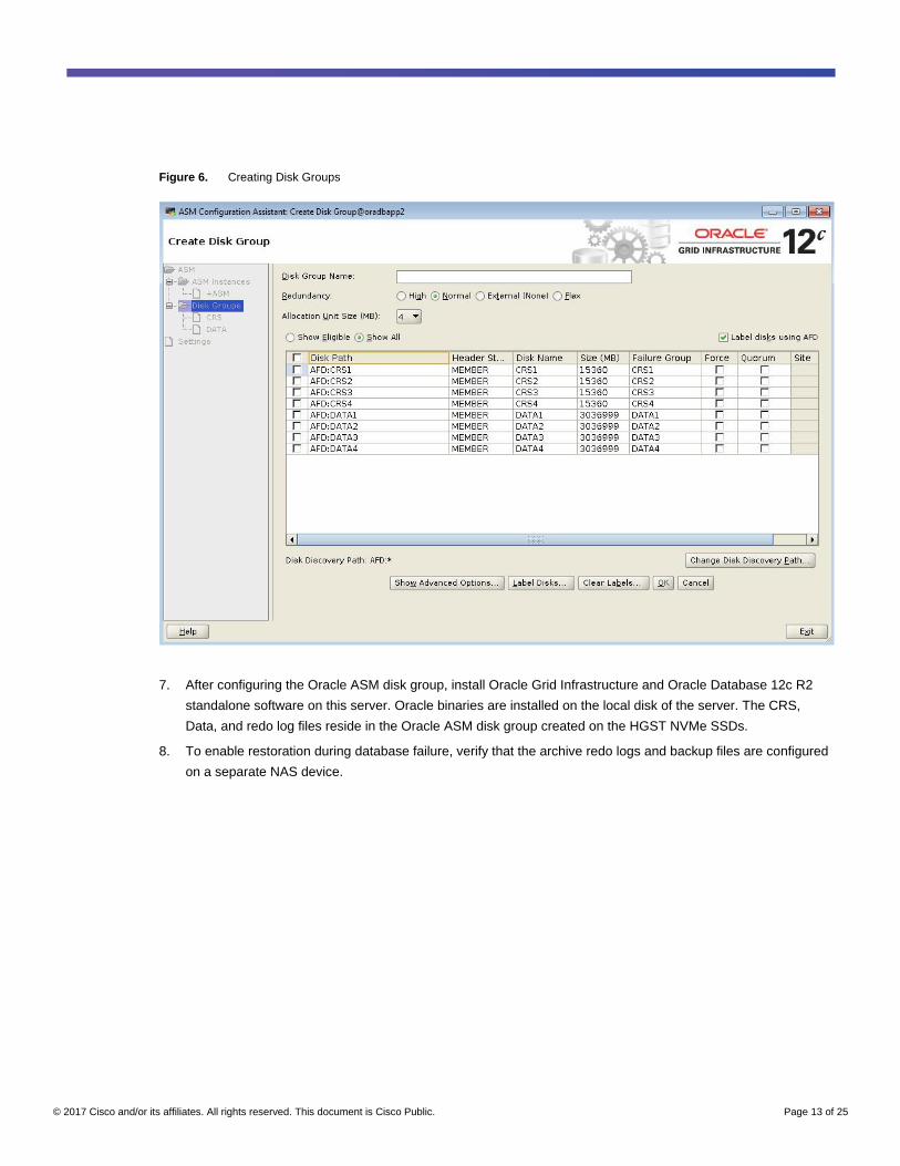
6. Configure Oracle Grid Infrastructure and Oracle Database with normal redundancy on the HGST NVMe SSDs.
Create Oracle ASM disk groups CRS and Data to store database files, as shown in Figure 6.
© 2017 Cisco and/or its affiliates. All rights reserved. This document is Cisco Public. Page 13 of 25
Figure 6. Creating Disk Groups
7. After configuring the Oracle ASM disk group, install Oracle Grid Infrastructure and Oracle Database 12c R2
standalone software on this server. Oracle binaries are installed on the local disk of the server. The CRS,
Data, and redo log files reside in the Oracle ASM disk group created on the HGST NVMe SSDs.
8. To enable restoration during database failure, verify that the archive redo logs and backup files are configured
on a separate NAS device.

© 2017 Cisco and/or its affiliates. All rights reserved. This document is Cisco Public. Page 14 of 25
Performance and Failover Analysis
This section discusses test scenarios that evaluate the performance of the Cisco UCS C220 M4 server with the
Ultrastar SN100 NVMe SSD for running standalone Oracle Database 12c R2.
A common practice is to evaluate system performance before deploying any database application. System
baseline performance testing is performed using common I/O calibration tools such the Linux Flexible I/O (FIO)
tool. The FIO tool can generate I/O patterns that mimic the type of I/O operations performed by Oracle databases.
FIO Results
The testing here used Linux FIO to measure I/O performance before Oracle Database was installed. This test
scenario analyzes FIO performance on a single NVMe SSD and on multiple NVMe SSDs.
Test 1: Performance for Single NVMe SSD
Figure 7 shows I/O tests with different read and write percentages and the corresponding IOPS values. The test
was run using random read and write operations for an 8-KB block size, with operations ranging from 100 to 0
percent read operations on a single NVMe SSD.
Figure 7. IOPS Results for One NVMe SSD
Test 2: Performance for Two NVMe SSDs
Figure 8 shows I/O tests at different read and write percentages and the corresponding IOPS values when the FIO
test is run on two NVMe cards together. The test was run using random read and write operations for an 8-KB
block size, with operations ranging from 100 to 0 percent read operations on two NVMe SSDs. In Figure 8, you can
see that you can achieve a reasonable IOPS value by adding NVMe devices on the same physical server.

© 2017 Cisco and/or its affiliates. All rights reserved. This document is Cisco Public. Page 15 of 25
Figure 8. IOPS Results for Two NVMe SSDs
Swingbench Configuration
This solution uses Swingbench for OLTP workload testing. Swingbench is a simple-to-use, free, Java-based tool
for generating database workloads and performing stress tests using different benchmarks in Oracle database
environments. For the tests described here, the Swingbench Order Entry (SOE) benchmark was used for OLTP
workload testing. The SOE benchmark is based on the SOE schema and is similar to Transaction Processing
Performance Council Benchmark C (TPC-C) in the types of transactions run. The workload uses a balanced read-
to-write ratio of about 60:40 and can be designed to run continuously to test the performance of a typical order-
entry workload against a small set of tables producing contention for database resources.
For this solution, one OLTP database (orcldb2) was created using the Oracle Database Configuration Assistant
(DBCA). In the OLTP database, one Swingbench user tablespace (sbts) with a size of 4 TB was created. The SOE
schema data is loaded into this tablespace. The NVMe Data disk group was used to store all the database files and
redo log files for the database, as shown in Figure 9.

© 2017 Cisco and/or its affiliates. All rights reserved. This document is Cisco Public. Page 16 of 25
Figure 9. Oracle Enterprise Manager Tablespace Layout
For this test, a 96-GB system global area (SGA) was configured, and the test was run for at least 12 hours to help
ensure the consistency of the results over the entire run. For OLTP workloads, the common measurements are
transactions per minute (TPM), number of users, and IOPS scalability. For the test, the SOE benchmark was run to
generate a workload on the server with the number of users varying from 50 to 300. Oracle Automatic Workload
Repository (AWR) reports were recorded for each scenario.
Swingbench Results
Figure 10 shows the TPM value and system utilization percentage when running the Swingbench workload with the
number of users scaling from 50 to 300.
Figure 10. User Scale and TPM
From the results shown here, you can see that the TPM value scales linearly as the number of users increases. As
shown in Figure 10, the total TPM value ranged from about 296,000 to 924,000 when scaling from 50 to 300 OLTP
users.

© 2017 Cisco and/or its affiliates. All rights reserved. This document is Cisco Public. Page 17 of 25
Also, CPU utilization in the system gradually increased, reflecting the linear scalability of the workload. For this
solution, the Cisco UCS C220 M4 server was equipped with a 2-socket Intel Xeon processor E5-2660 v3 running at
2.6 GHz. A bottleneck occurred because of the CPU capacity of the server. Storage latency was always less than a
millisecond throughout the test.
Figure 11 shows the I/O statistics captured while running the Swingbench workload for 300 users. The number of
sectors read (rkB/s) and written (wkB/s) from the device per second was equally distributed across all NVMe
devices. The average time (in milliseconds) for read requests (r_await) and write requests (w_await) issued to the
device observed was less than 0.2 millisecond; this value includes the time the requests spent in the queue and
the time spent servicing the requests together. Similar I/O statistics were achieved throughout the test scenario.
Figure 11. I/O Statistics
As shown in Figure 12, the maximum IOPS value generated was about 123,000 IOPS, when the system was
scaled to 300 OLTP users.
Figure 12. User Scale and IOPS
Database performance was also evaluated using the Top 10 events from Oracle AWR reports with 300 users, as
shown in Figure 13.

© 2017 Cisco and/or its affiliates. All rights reserved. This document is Cisco Public. Page 18 of 25
Figure 13. Database Performance for Top 10 Events
The latency was about 0.4 millisecond during the test run while running a workload with 300 users. Figure 14
shows the results captured from Oracle Enterprise Manager.
Figure 14. Latency Results
Performance Impact of Failure of One NVMe Device
The goal of this test is to help ensure that this solution withstands a failure resulting from an unexpected system
crash or hardware failure. This section discusses an HGST NVMe SSD failure on a Cisco UCS C220 M4 server
and the best practices for restoring the system to normal running condition.
Note: Hot insertion and OS informed removal are supported only with Cisco IMC Release 2.0(13) and later and
depend on the OS version. As of this writing, Cisco UCS Manager does not support these features.

© 2017 Cisco and/or its affiliates. All rights reserved. This document is Cisco Public. Page 19 of 25
Here, several tests were performed by pulling out or deleting partitions on one of the NVMe SSDs while the system
is running a full workload. The main goals were to measure the following:
● Impact of the NVMe SSD failure on system performance when the workload is running
● Server downtime while replacing a failed NVMe SSD with a new NVMe SSD device
● Rebalancing time for the Oracle ASM disk group under different workload scenarios
● Latency during failure of an NVMe SSD and rebalancing of the ASM disk group while the workload is
running
For this test, the Swingbench workload was run with 250 users, and the system CPU was saturated, with around
85 percent utilization. The logical observations during NVMe SSD failure are explained here.
Observation 1: Impact on System Performance of Failure of Any One NVMe SSD While Workload Is Running
When the system was running a workload, one of the disk groups on one NVMe SSD device was taken offline.
Figure 15 shows the captured I/O statistics.
Figure 15. System Performance Impact with One NVMe SSD Failure While Workload Is Running
In Figure 15, you can see that the nvme3n1 device failed and could not perform any I/O operations. The failure had
no significant performance impact on TPM, IOPS, or latency throughout the test. Also, hot removal of the NVMe
SSD was performed by pulling out the device. This sudden hot removal of NVMe SSD did not cause the system to
fail. The system workload can still continue to run without any performance impact until the next maintenance
window is available.

© 2017 Cisco and/or its affiliates. All rights reserved. This document is Cisco Public. Page 20 of 25
Observation 2: Impact of Replacing Failed NVMe SSD with New NVMe SSD
When a maintenance window is available, replace the failed NVMe SSD with a new NVMe SSD. Use the following
high-level steps to restore the system to its normal condition:
1. Shut down the Oracle Database and ASM instance.
2. Insert a new HGST NVMe SSD and reboot the server.
3. As described earlier in the document, to configure the NVMe SSD, scan the new NVMe SSD, resize it to 3.2
TB, and reboot the server to format the new NVMe SSD.
4. After the server boot is complete, create a partition to match the existing ASM disk groups and use the Oracle
ASM command-line tool (ASMCMD) to provision the new NVMe partition to use with the Oracle ASMFD.
5. Verify that the device has been marked for use with the Oracle ASMFD.
6. Start the ASM instance, mount the CRS and Data disk groups, and start Oracle Database.
7. Replace the NVMe partition disks for the CRS and Data disk groups.
In this test, the system experienced around 15 to 20 minutes of downtime while replacing the failed NVMe SSD
and configuring the new NVMe SSD after the failure of one NVMe SSD.
Observation 3: Rebalancing Time Needed for ASM Disk Group for a Different Workload Scenario
After you configure a new NVMe SSD, you have multiple options for rebalancing the ASM disk group, depending
on the database workloads. Various tests were performed with and without workload to measure the rebalancing
operation time for the ASM disk group, as summarized in Table 3.
Table 3. Rebalancing Time After Configuring a New NVMe SSD
Scenario Task Rebuild Time
Option 1: Rebuild the disk group first; then start the workload
Start the database. No transactions are performed during the rebalance operation. Rebalance the disk group with power 8.
10 to 15 minutes
Option 2: Rebuild the disk group normally with the workload
Start the database. Transactions are performed during the rebalance operation. Rebalance the disk group with power 4.
60 to 70 minutes
Option 3: Rebuild the disk group aggressively with the workload
Start the database. Transactions are performed during the rebalance operation. Rebalance the disk group with power 8.
40 to 50 minutes
Option 1: In this scenario, we started rebalancing the ASM disk group without any database workload and waited
until the rebalancing operation finished. After the ASM disk group finished rebalancing, we started the database
workload and saw the results shown in Figure 16.

© 2017 Cisco and/or its affiliates. All rights reserved. This document is Cisco Public. Page 21 of 25
Figure 16. Option 1 Results
In Figure 16, you can see that the system experienced around 15 minutes of downtime during the process of
replacing the failed NVMe SSD and configuring the new NVMe SSD. The rebalancing operation on the ASM disk
group without any workload took around 10 to 15 minutes to complete. The system then was restored to the normal
running phase.

© 2017 Cisco and/or its affiliates. All rights reserved. This document is Cisco Public. Page 22 of 25
Option 2: In this scenario, we started rebalancing the ASM disk group and full database workload at the same
time. The rebalance disk group was started with power 4. Figure 17 shows the time recorded to complete the
rebalance operation on the ASM disk group.
Figure 17. Option 2 Results
In Figure 17, you can see the system experienced around 15 minutes of downtime during the process of replacing
the failed NVMe SSD and configuring the new NVMe SSD. The rebalancing operation on the ASM disk group with
the system running a full workload took around 60 to 70 minutes to complete. The system then was restored to
normal running condition.

© 2017 Cisco and/or its affiliates. All rights reserved. This document is Cisco Public. Page 23 of 25
Option 3: In this scenario, we started rebalancing the ASM disk group and full database workload at the same
time. The rebalance disk group was started with power 8. Figure 18 shows the time recorded to complete the
rebalance operation on the ASM disk group.
Figure 18. Option 3 Results
In Figure 18, you can see the system experienced around 15 minutes of downtime during the process of replacing
the failed NVMe SSD and configuring the new NVMe SSD. The rebalancing operation on the ASM disk group with
the system running a full workload took around 40 to 50 minutes to complete. The system then was restored to
normal running condition.

© 2017 Cisco and/or its affiliates. All rights reserved. This document is Cisco Public. Page 24 of 25
Figure 19 shows all the rebalancing options and system performance for the database during the NVMe SSD
failure and replacement process.
Figure 19. Rebalancing Options and System Performance
Observation 4: The tests recorded latency from Oracle Enterprise Manager as well as AWR reports during
rebalancing of the ASM disk group in various workload scenarios. When the system was running workloads and
disk group rebalancing was started with power 4, average latency of 0.7 millisecond was recorded. When the
system was running workloads and disk group rebalancing was started with power 8, average latency of 1.2
milliseconds was recorded.
Conclusion
The Cisco UCS C220 M4 Rack Server is a versatile enterprise server that delivers world-record performance for a
wide range of enterprise workloads, including virtualization, collaboration, and bare-metal applications. It also
delivers outstanding levels of expandability and performance in a compact 1RU package. The combination of the
Cisco UCS C220 M4 Rack Server and HGST SN100 PCIe SSDs significantly improves performance for
organizations running standalone Oracle Database 12c. Organizations also gain the benefits of lower total cost of
acquisition and lower TCO through reduced data center power and cooling needs, lower cost per IOPS, and lower
wattage requirements per IOPS.
Cisco UCS C-Series Rack Servers with HGST SN100 PCIe SSDs offer significantly reduced complexity compared
to most competing solutions, which require manual command-line interface (CLI) processes for each PCIe-
connected device. This high-performance solution is simple and easy to deploy at a lower cost than other popular
SAN storage systems. Linear scaling of resource utilization was observed for both the storage and server
resources while running OLTP database workloads.
During a server failure, system downtime is decreased by direct attachment to the Cisco UCS rack server,
unleashing the full capabilities of Cisco UCS stateless computing. By deploying Cisco UCS rack servers with

© 2017 Cisco and/or its affiliates. All rights reserved. This document is Cisco Public. Page 25 of 25
HGST NVMe SSDs and Oracle Database, organizations gain an enterprise-class, high-performance, reliable, low-
latency, scalable solution.
For More Information
For more information about Cisco data center design for Oracle applications and HGST solid-state products, see
the following resources:
● Data center design guides on Cisco UCS:
http://www.cisco.com/c/en/us/solutions/design-zone/data-center-design-guides/data-center-design-guides-
all.html?wcmmode=disabled - ORCapps
● Cisco UCS servers:
http://www.cisco.com/c/en/us/products/servers-unified-computing/product-listing.html
● Cisco UCS C-Series Rack Servers:
http://www.cisco.com/c/en/us/products/servers-unified-computing/ucs-c-series-rack-servers/index.html
● HGST Ultrastar PCIe SSD:
https://www.hgst.com/products/solid-state-solutions/ultrastar-sn100-series
● HGST Device Manager user guide:
http://www.hgst.com/sites/default/files/resources/HGST-Device-Manager-3.2-UserGuide.pdf
● Oracle Database 12c Release 2:
https://docs.oracle.com/database/122/index.html
● Cisco NVMe data sheet:
http://www.cisco.com/c/en/us/products/collateral/servers-unified-computing/ucs-c-series-rack-
servers/datasheet-c78-737708.html
Printed in USA C11-739080-00 05/17