deploying brocade 8 gbps with vmware virtua infrastructure
TRANSCRIPT

Deploying VMware Virtual Infrastructure 3.5 in a Heterogeneous Server
and Storage Environment Using a Brocade 8 Gbps Infrastructure
Executive Summary
This paper provides guidance for setting up a VMware® ESX 3.5 environment based on
heterogeneous storage and server components and Brocade infrastructure (hardware and software
products). The following technology components were deployed:
Brocade® 5100 8 Gbps Fibre Channel Switches
Brocade 825 (dual port) 8 Gbps Fibre Channel‐to‐PCIe Host Bus Adapters (HBAs)
HP® ProLiant DL380 G5 Servers
HP ProLiant BL460/480C Blade Servers
HP Virtual Connect Fibre Channel
Dell® PowerEdge 2950 III Servers
HP EVA4400 Disk Array
EMC® CX4‐120 Disk Array
This paper is intended to provide an end‐to‐end view of successfully deploying a Virtual Machine
environment utilizing the benefits of a high‐performance Brocade 8 Gbps Fibre Channel environment
to provided enhanced performance and availability to different Virtual Machine (VM) types along
with best practices and easy‐to‐use setup and configuration instructions. However, this paper is not
intended to replace any documentation supplied with the individual components.
Introduction
Server virtualization has become a fundamental technology in most data center environments. A
virtual infrastructure offers a variety of benefits, ranging from more efficient use of resources and
reduction of server sprawl to the financial side of reduced capital expenditures.
Among the different server virtualization vendors, VMware currently has the broadest market share
and offers a wide variety of technologies to manage, maintain and improve resource utilization and
performance. With the advent of multi‐core processors, CPU power is no longer the bottleneck for
deploying large numbers of Virtual Machines on a single VMware ESX Server. Storage capacity
requirements are steadily growing because of the rapidly growing numbers of Virtual Machines. Fibre
Channel SANs are the first choice for providing shared storage to ESX Server environments and
VMware ESX DRS and HA clusters. SAN‐based backup has also evolved into a commodity.
Many different factors have increased the demand for higher performance and more granular
control of storage workloads related to individual Virtual Machines and their respective applications.
In September 2008, Brocade 815/825 HBAs were certified for VMware ESX. The Brocade 815 (single
port) and 825 (dual port) 8 Gbps Fibre Channel HBAs in conjunction with the Brocade 8 Gbps Fibre
Channel Switch platform allows for homogeneous Brocade 8 Gbps server‐to‐storage connectivity.
This Brocade 8 Gbps solution is the focus of this paper.
This paper includes the following topics:
Setting up a Brocade switch infrastructure (based on the Brocade 5100)
Setting up host connectivity with Brocade HBAs
Setting up boot from FC with Brocade HBAs
Setting up a VMware ESX Server I3.5 environment with Brocade
Streamlining virtualized workloads on ESX Server I3.5 with an 8 Gbps infrastructure
NPIV for workload optimization
SMI‐S and monitoring basics and introduction
Review of connectivity best practices and basic layout considerations
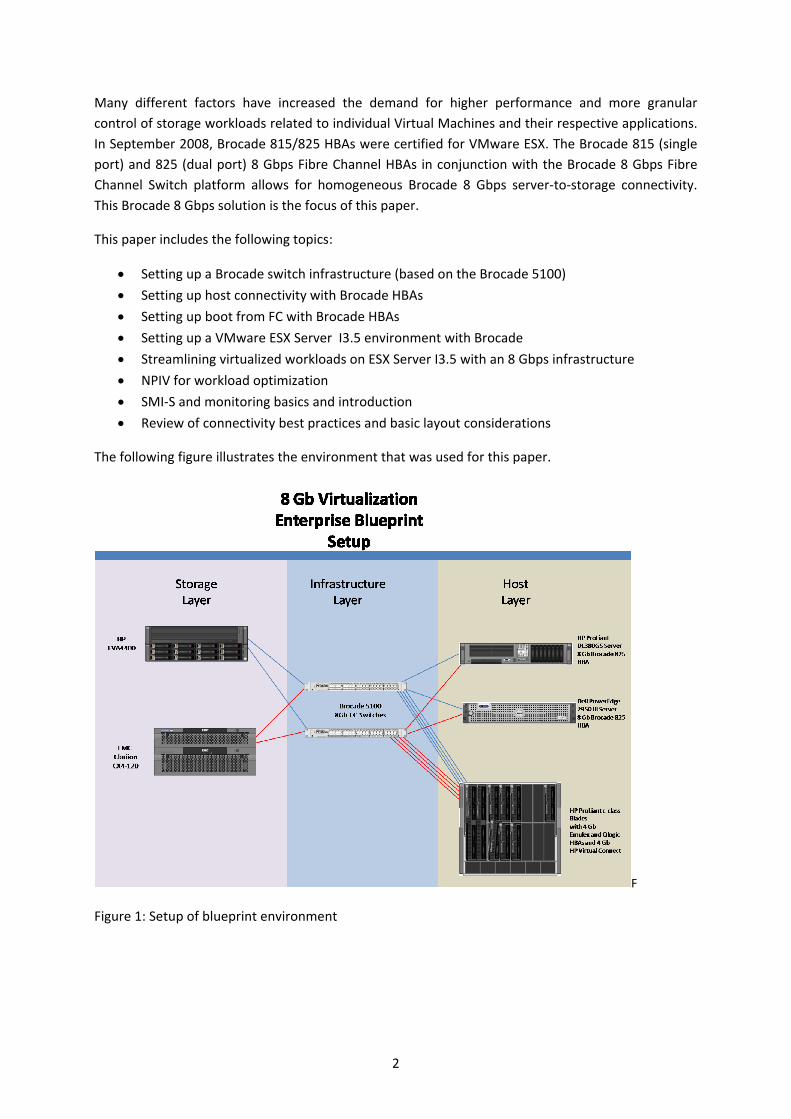
The following figure illustrates the environment that was used for this paper.
F
Figure 1: Setup of blueprint environment
2

Part 1: Infrastructure Considerations and Best Practices
Setting Up Storage
Setting up storage for a VMware ESX environment seems to be easy at a first glance. Taking a closer
look at the storage requirements, one will find a more complicated truth. Eventually, there are three
basic use cases for storage presented to an ESX Server:
Boot LUN
The ESX Server can be installed to boot from a local SCSI disk or to boot from SAN. In both
cases, the LUN is usually partitioned into six default partitions, which belong either to the ESX
service console or to the VMkernel. Usually, a VMFS partition is created to fill up the
remaining space on a local SCSI disk.
When booting from SAN, the storage administrator can size the boot LUN in a granular
manner, so it is a best practice not to create a VMFS on the boot LUN, but rather have the
VMFSes reside on dedicated LUNs. The following figure demonstrates a typical boot‐from‐
SAN configuration.
Figure 2: Boot‐from‐SAN configuration
Usually, the size of the boot LUN does not exceed 25 GB. Performance requirements for the
boot LUN are low to moderate.
VMFS Datastore
The VMFS is a file system specifically designed to host Virtual Machine files, especially the
large Virtual Machine Disk (VMDK) files (.vmdk). The VMFS is designed to keep SCSI
reservations at a minimum to allow for seamless operation of multiple VMs on the same
datastore.
3
From a VI3 management perspective, the administrator should try to keep the number of
VMFS datastores low. On the other hand, this can of course lead to performance bottlenecks
when too many Virtual Machine disk files are placed onto the same VMFS, i.e. the same LUN,
especially, if multiple Virtual Machine disks require higher I/O rates or higher sequential
throughput.
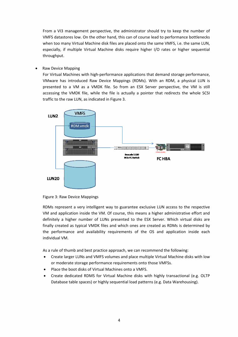
Raw Device Mapping
For Virtual Machines with high‐performance applications that demand storage performance,
VMware has introduced Raw Device Mappings (RDMs). With an RDM, a physical LUN is
presented to a VM as a VMDK file. So from an ESX Server perspective, the VM is still
accessing the VMDK file, while the file is actually a pointer that redirects the whole SCSI
traffic to the raw LUN, as indicated in Figure 3.
Figure 3: Raw Device Mappings
RDMs represent a very intelligent way to guarantee exclusive LUN access to the respective
VM and application inside the VM. Of course, this means a higher administrative effort and
definitely a higher number of LUNs presented to the ESX Server. Which virtual disks are
finally created as typical VMDK files and which ones are created as RDMs is determined by
the performance and availability requirements of the OS and application inside each
individual VM.
As a rule of thumb and best practice approach, we can recommend the following:
Create larger LUNs and VMFS volumes and place multiple Virtual Machine disks with low
or moderate storage performance requirements onto those VMFSs.
Place the boot disks of Virtual Machines onto a VMFS.
Create dedicated RDMS for Virtual Machine disks with highly transactional (e.g. OLTP
Database table spaces) or highly sequential load patterns (e.g. Data Warehousing).
4

Depending on the environment size and IT strategy, LUNs may also be presented from
different arrays (same or different vendors) to reflect different performance and availability
requirements. In the end, LUNs will be presented from the Array to the ESX Server or ESX
Server cluster, which involves the second infrastructure layer, the SAN fabric.
Setting Up the Switch Infrastructure
The Fibre Channel fabric, or switch infrastructure, plays the central role in connecting storage and
servers. Performance, availability, and security are fundamental building blocks of a stable storage
networking strategy. This applies to physical and virtual environments alike. However, the impact of
losing access to the storage device is much higher on an ESX Server that is running 20 or 30 Virtual
Machines (and applications) than on a physical server that is running a single application only.
Zoning is the standard way to provide SAN‐based security. Simply speaking, zoning is the partitioning
of a Fibre Channel fabric into smaller subsets to restrict interference, add security, and to simplify
management. If a SAN contains several storage devices, similar to our blueprint environment,
systems connected to the SAN should not be allowed to interact with all storage devices.
Zoning is sometimes confused with LUN masking, because it serves the same goals. LUN masking,
however, works on the array or SCSI level, while zoning works on the Fibre Channel port or WWN
level. Port‐level zoning (commonly referred to as hard zoning) and WWN‐level zoning (commonly
referred to as soft zoning) may be combined depending on the specific requirements. However,
WWN‐based zoning is more flexible and allows for faster reconfigurations of the physical
environment.
Regardless of the actual zoning approach—hard or soft—there is one best practice that should be
respected anywhere and also in ESX Server environments. This practice is called single‐
initiator/single‐target‐zoning.
Depending on your environment, you can benefit from isolating traffic as much as possible in your
storage area network. SANs with a large number of storage volumes (e.g. when you have presented a
lot of RDMs) and heavy host traffic can benefit the most. Implementing single‐initiator/single‐target
zoning allows you to isolate traffic for each port. Single‐initiator, single‐target zoning creates small
zones in the fabric with only two zone members (ports or WWNs). The zone consists of one target (a
storage unit port), and one initiator (a host system port). The key benefit of single‐initiator/single‐
target zoning is traffic isolation or masking. Though it looks like a huge initial effort to create a larger
number of zones, the benefits are increased stability and simplified fault isolation and
troubleshooting.
5
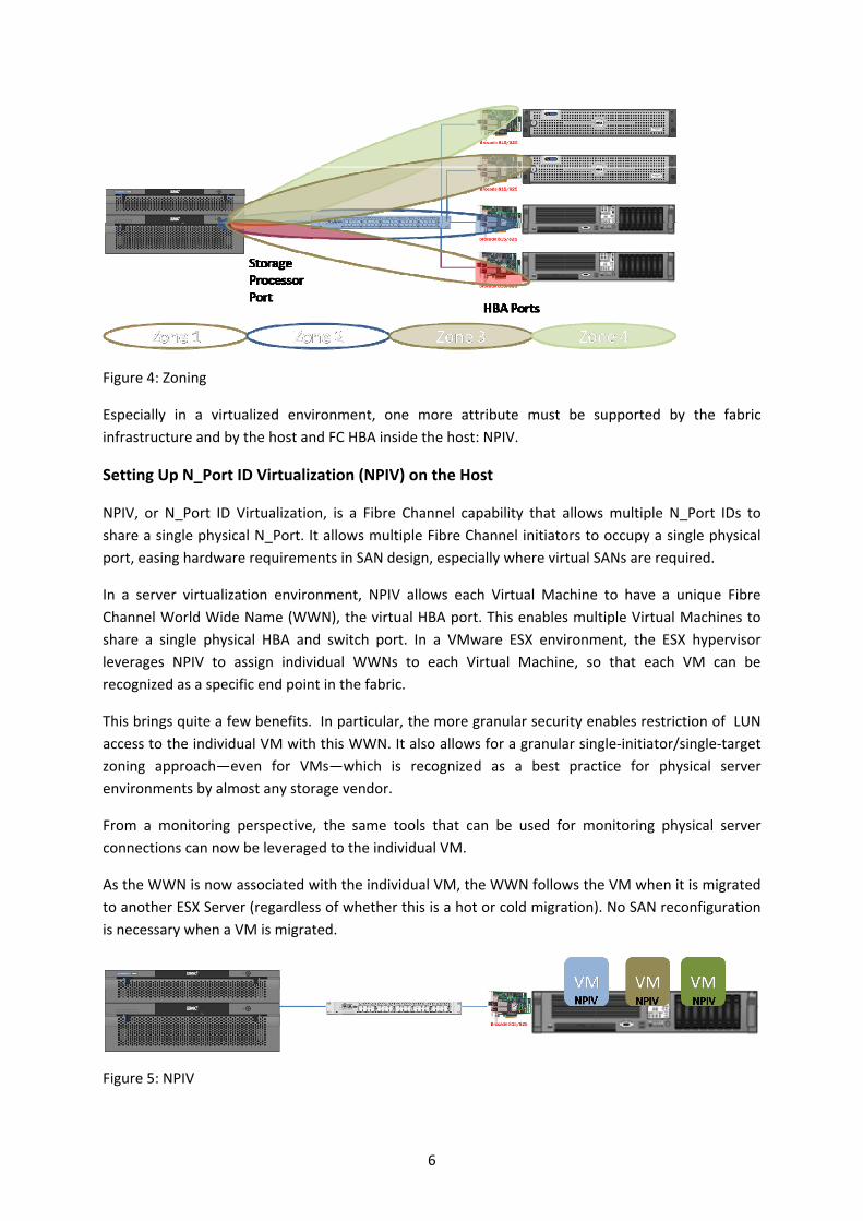
Figure 4: Zoning
Especially in a virtualized environment, one more attribute must be supported by the fabric
infrastructure and by the host and FC HBA inside the host: NPIV.
Setting Up N_Port ID Virtualization (NPIV) on the Host
NPIV, or N_Port ID Virtualization, is a Fibre Channel capability that allows multiple N_Port IDs to
share a single physical N_Port. It allows multiple Fibre Channel initiators to occupy a single physical
port, easing hardware requirements in SAN design, especially where virtual SANs are required.
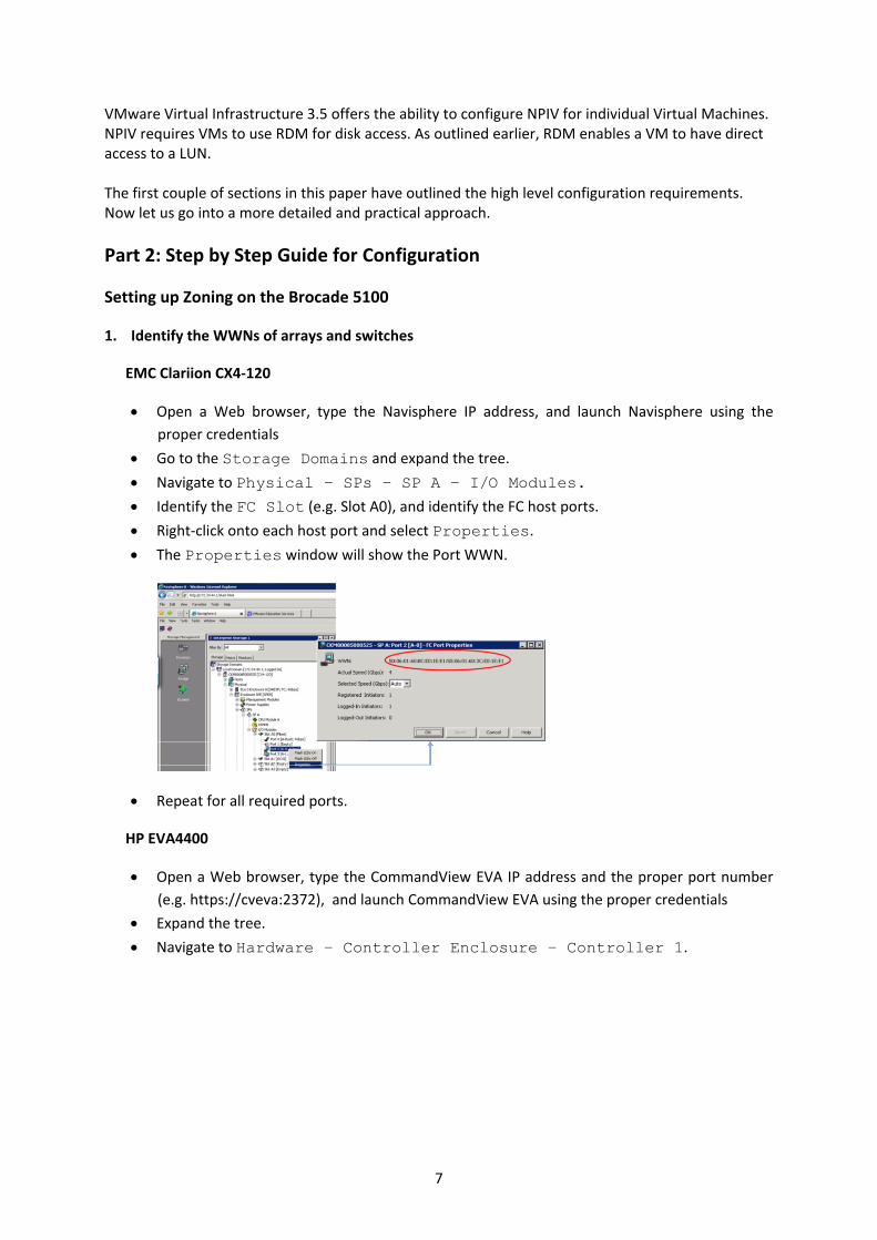
In a server virtualization environment, NPIV allows each Virtual Machine to have a unique Fibre
Channel World Wide Name (WWN), the virtual HBA port. This enables multiple Virtual Machines to
share a single physical HBA and switch port. In a VMware ESX environment, the ESX hypervisor
leverages NPIV to assign individual WWNs to each Virtual Machine, so that each VM can be
recognized as a specific end point in the fabric.
This brings quite a few benefits. In particular, the more granular security enables restriction of LUN
access to the individual VM with this WWN. It also allows for a granular single‐initiator/single‐target
zoning approach—even for VMs—which is recognized as a best practice for physical server
environments by almost any storage vendor.
From a monitoring perspective, the same tools that can be used for monitoring physical server
connections can now be leveraged to the individual VM.
As the WWN is now associated with the individual VM, the WWN follows the VM when it is migrated
to another ESX Server (regardless of whether this is a hot or cold migration). No SAN reconfiguration
is necessary when a VM is migrated.
Figure 5: NPIV
6
VMware Virtual Infrastructure 3.5 offers the ability to configure NPIV for individual Virtual Machines. NPIV requires VMs to use RDM for disk access. As outlined earlier, RDM enables a VM to have direct access to a LUN. The first couple of sections in this paper have outlined the high level configuration requirements. Now let us go into a more detailed and practical approach.
Part 2: Step by Step Guide for Configuration
Setting up Zoning on the Brocade 5100
1. Identify the WWNs of arrays and switches
EMC Clariion CX4‐120
Open a Web browser, type the Navisphere IP address, and launch Navisphere using the
proper credentials
Go to the Storage Domains and expand the tree.
Navigate to Physical – SPs – SP A – I/O Modules.
Identify the FC Slot (e.g. Slot A0), and identify the FC host ports.
Right‐click onto each host port and select Properties.
The Properties window will show the Port WWN.
Repeat for all required ports.
HP EVA4400
Open a Web browser, type the CommandView EVA IP address and the proper port number
(e.g. https://cveva:2372), and launch CommandView EVA using the proper credentials
Expand the tree.
Navigate to Hardware – Controller Enclosure – Controller 1.
7

In the right‐hand pane, click the Host Ports tab, which will show the WWNs.
Repeat for controller 2.
Host with Brocade 825 HBA
Boot the host and wait until the POST displays the Brocade BIOS.
Press ALT‐B to enter the BIOS.
The WWNs are displayed.
2. Configure zoning on the Brocade 5100 Switch
Log in to Brocade Web Tools via a Web browser with the correct switch IP address and
proper credentials.
Launch the Switch Name Server and identify, which WWNs/components are connected to
which ports.
Then launch the Zone Admin.
o Select the Alias tab.
o Select New and specify a name for this port/WWN then confirm OK.
o From the Member Selection List, select the proper WWN (identified earlier) and click
Add Member.
8
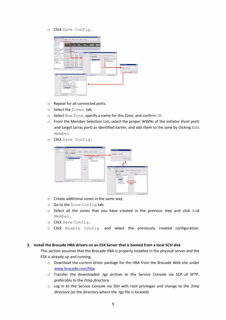
o Click Save Config.
o Repeat for all connected ports.
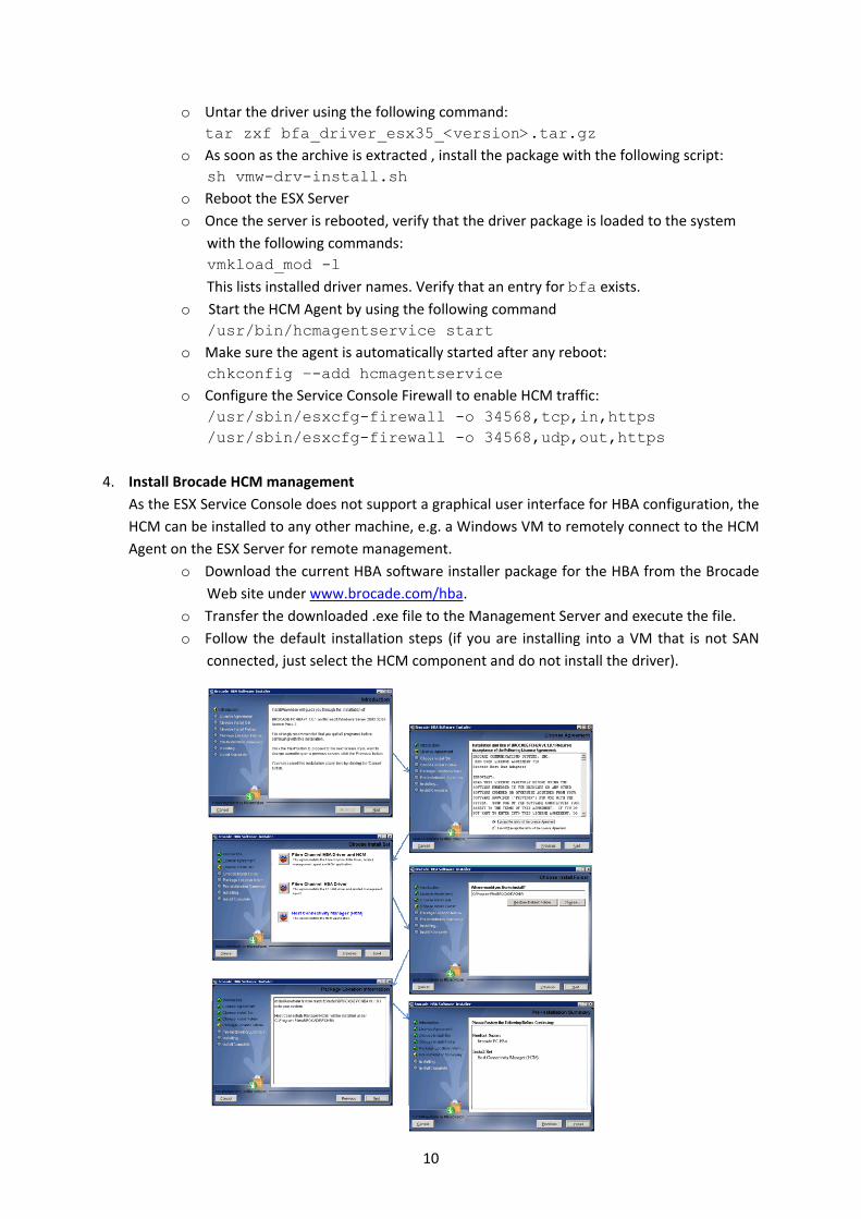
o Select the Zones tab.
o Select New Zone, specify a name for this Zone, and confirm OK. o From the Member Selection List, select the proper WWNs of the initiator (host port)
and target (array port) as identified earlier, and add them to the zone by clicking Add
Member.
o Click Save Config.
o Create additional zones in the same way.
o Go to the Zone Config tab.
o Select all the zones that you have created in the previous step and click Add Member.
o Click Save Config.
o Click Enable Config and select the previously created configuration.
3. Install the Brocade HBA drivers on an ESX Server that is booted from a local SCSI disk
This section assumes that the Brocade HBA is properly installed in the physical server and the
ESX is already up and running.
o Download the current driver package for the HBA from the Brocade Web site under
www.brocade.com/hba.
o Transfer the downloaded .tgz archive to the Service Console via SCP of SFTP,
preferably to the /tmp directory.
o Log in to the Service Console via SSH with root privileges and change to the /tmp
directory (or the directory where the .tgz file is located).
9
o Untar the driver using the following command:
tar zxf bfa_driver_esx35_<version>.tar.gz o As soon as the archive is extracted , install the package with the following script:
sh vmw-drv-install.sh o Reboot the ESX Server
o Once the server is rebooted, verify that the driver package is loaded to the system
with the following commands:
vmkload_mod -l
This lists installed driver names. Verify that an entry for bfa exists. o Start the HCM Agent by using the following command
/usr/bin/hcmagentservice start o Make sure the agent is automatically started after any reboot:
chkconfig –-add hcmagentservice o Configure the Service Console Firewall to enable HCM traffic:
/usr/sbin/esxcfg-firewall -o 34568,tcp,in,https /usr/sbin/esxcfg-firewall -o 34568,udp,out,https
4. Install Brocade HCM management
As the ESX Service Console does not support a graphical user interface for HBA configuration, the
HCM can be installed to any other machine, e.g. a Windows VM to remotely connect to the HCM
Agent on the ESX Server for remote management.
o Download the current HBA software installer package for the HBA from the Brocade
Web site under www.brocade.com/hba.
o Transfer the downloaded .exe file to the Management Server and execute the file.
o Follow the default installation steps (if you are installing into a VM that is not SAN
connected, just select the HCM component and do not install the driver).
10
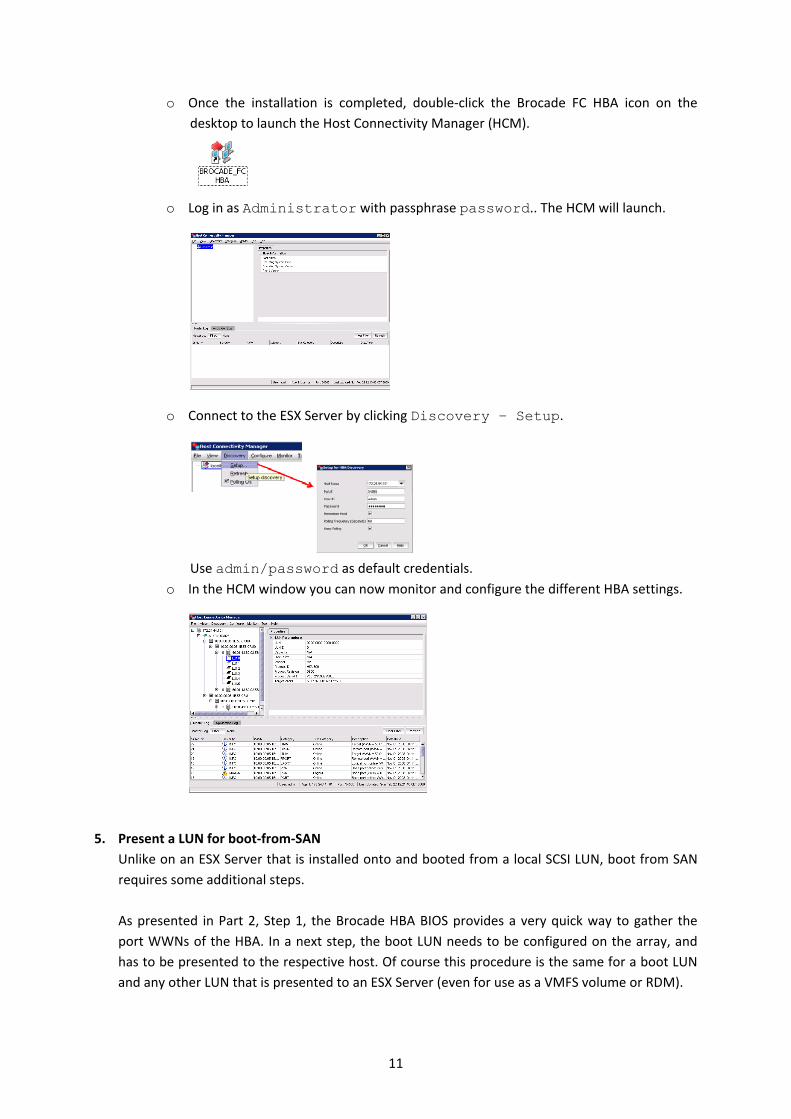
o Once the installation is completed, double‐click the Brocade FC HBA icon on the
desktop to launch the Host Connectivity Manager (HCM).
o Log in as Administrator with passphrase password.. The HCM will launch.
o Connect to the ESX Server by clicking Discovery – Setup.
Use admin/password as default credentials. o In the HCM window you can now monitor and configure the different HBA settings.
5. Present a LUN for boot‐from‐SAN
Unlike on an ESX Server that is installed onto and booted from a local SCSI LUN, boot from SAN
requires some additional steps.
As presented in Part 2, Step 1, the Brocade HBA BIOS provides a very quick way to gather the
port WWNs of the HBA. In a next step, the boot LUN needs to be configured on the array, and
has to be presented to the respective host. Of course this procedure is the same for a boot LUN
and any other LUN that is presented to an ESX Server (even for use as a VMFS volume or RDM).
11

EMC Clariion CX4‐120
Open a Web browser, type the Navisphere IP address, and launch Navisphere using the
proper credentials.
o Right‐click on the array icon and select Connectivity Status.
o Click New. o For Initiator Name, enter the WWNN and WWPN of the Brocade HBA in the following
format: WWNN:WWPN (e.g. 20:00:00:05:1e:56:c7:80:10:00:00:05:1e:56:c7:80)
Choose New Host and provide the Name and IP address.
Confirm OK and finalize the configuration by confirming the pop‐up messages.
o From the Storage Groups tab, select the storage group name and the host, right‐
click on the host, and select Connectivity Status.
12
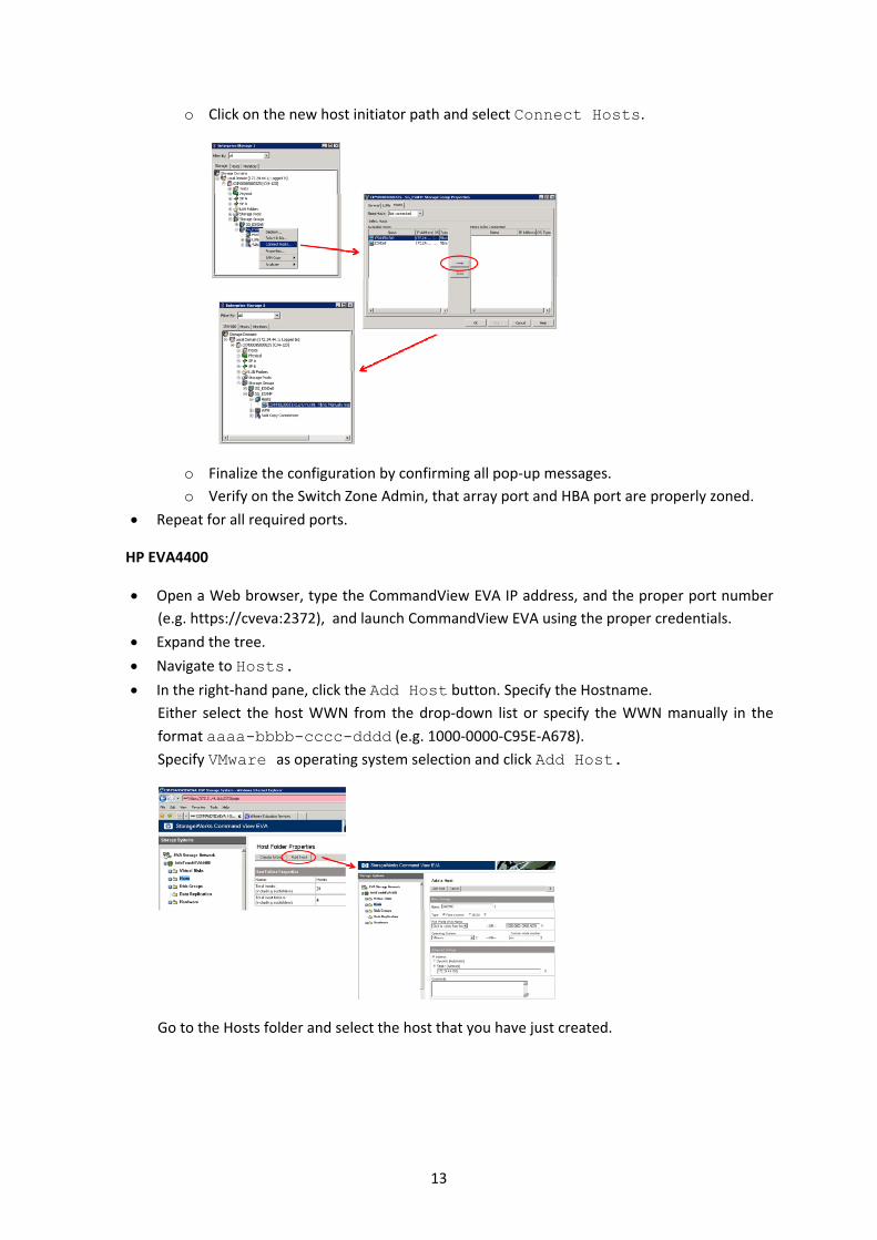
o Click on the new host initiator path and select Connect Hosts.
o Finalize the configuration by confirming all pop‐up messages.
o Verify on the Switch Zone Admin, that array port and HBA port are properly zoned.
Repeat for all required ports.
HP EVA4400
Open a Web browser, type the CommandView EVA IP address, and the proper port number
(e.g. https://cveva:2372), and launch CommandView EVA using the proper credentials.
Expand the tree.
Navigate to Hosts.
In the right‐hand pane, click the Add Host button. Specify the Hostname.
Either select the host WWN from the drop‐down list or specify the WWN manually in the
format aaaa-bbbb-cccc-dddd (e.g. 1000‐0000‐C95E‐A678).
Specify VMware as operating system selection and click Add Host.
Go to the Hosts folder and select the host that you have just created.
13

Click Add Port and specify the WWN of the second HBA port, then confirm.
Verify that both WWNs are listed.
Expand the tree again.
Navigate to Virtual Disks.
In the right‐hand pane, click the Create Vdisk button.
Specify a vdisk name, VRaid level, and disk size, and click Create Vdisk to create this disk.
In the Virtual Disks folder, go to the recently created vdisk.
In the right‐hand pane, select the Presentation tab, and then click the Present button.
In the host selection list, select the Host and click Assign LUN.
14
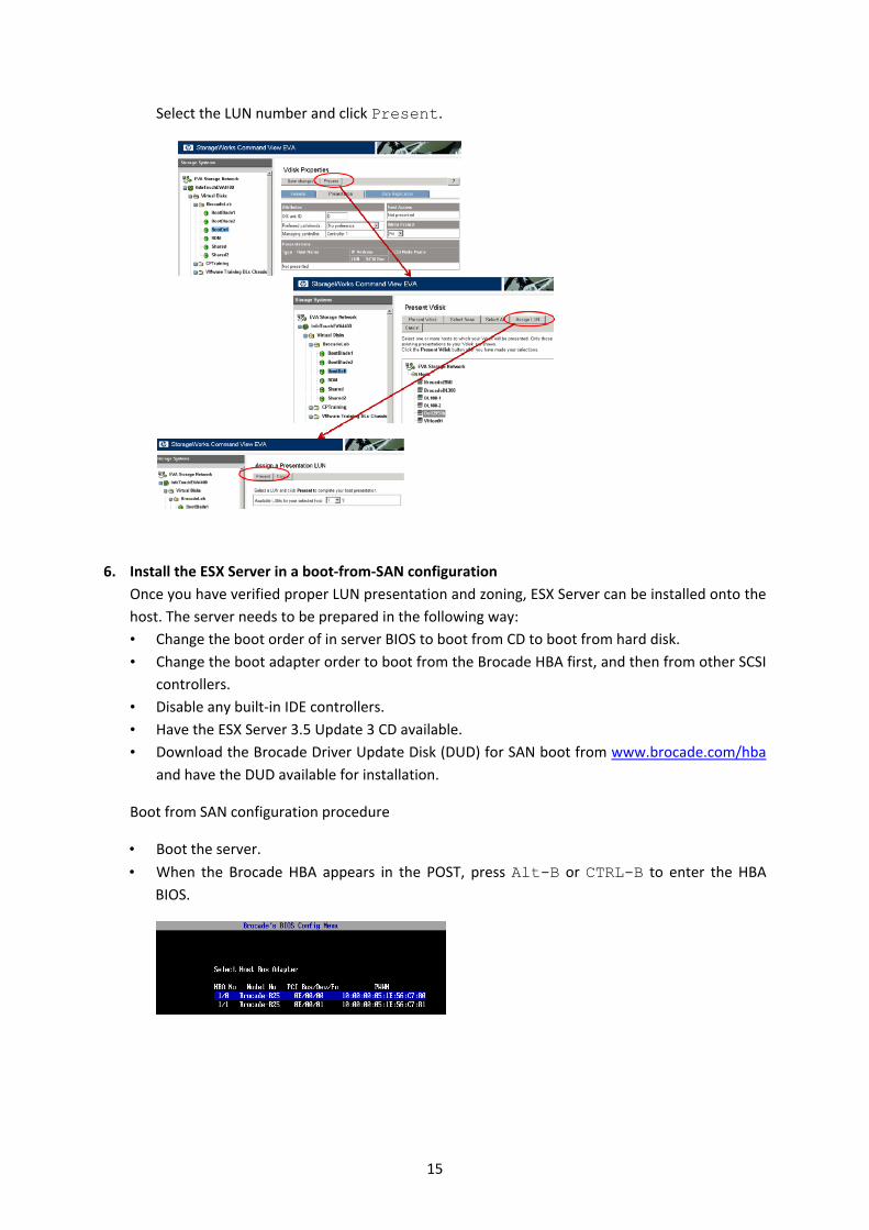
Select the LUN number and click Present.
6. Install the ESX Server in a boot‐from‐SAN configuration
Once you have verified proper LUN presentation and zoning, ESX Server can be installed onto the
host. The server needs to be prepared in the following way:
• Change the boot order of in server BIOS to boot from CD to boot from hard disk.
• Change the boot adapter order to boot from the Brocade HBA first, and then from other SCSI
controllers.
• Disable any built‐in IDE controllers.
• Have the ESX Server 3.5 Update 3 CD available.
• Download the Brocade Driver Update Disk (DUD) for SAN boot from www.brocade.com/hba
and have the DUD available for installation.
Boot from SAN configuration procedure
• Boot the server.
• When the Brocade HBA appears in the POST, press Alt-B or CTRL-B to enter the HBA BIOS.
15

• Select the first adapter and choose Adapter Settings.
• Make sure that the following settings are applied: BIOS – Enabled Port Speed – Auto Boot LUN – First LUN
• Press ESC to go back into the main menu, and select the Boot Device Settings entry.
The WWNs presented in the next screen are the visible array target ports.
• Select the first array port WWN.
16
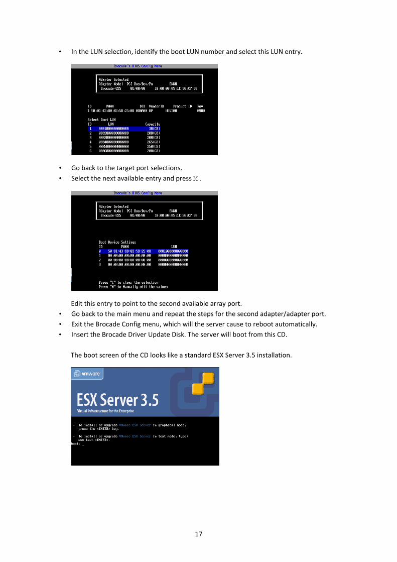
• In the LUN selection, identify the boot LUN number and select this LUN entry.
• Go back to the target port selections.
• Select the next available entry and press M .
Edit this entry to point to the second available array port.
• Go back to the main menu and repeat the steps for the second adapter/adapter port.
• Exit the Brocade Config menu, which will the server cause to reboot automatically.
• Insert the Brocade Driver Update Disk. The server will boot from this CD.
The boot screen of the CD looks like a standard ESX Server 3.5 installation.
17
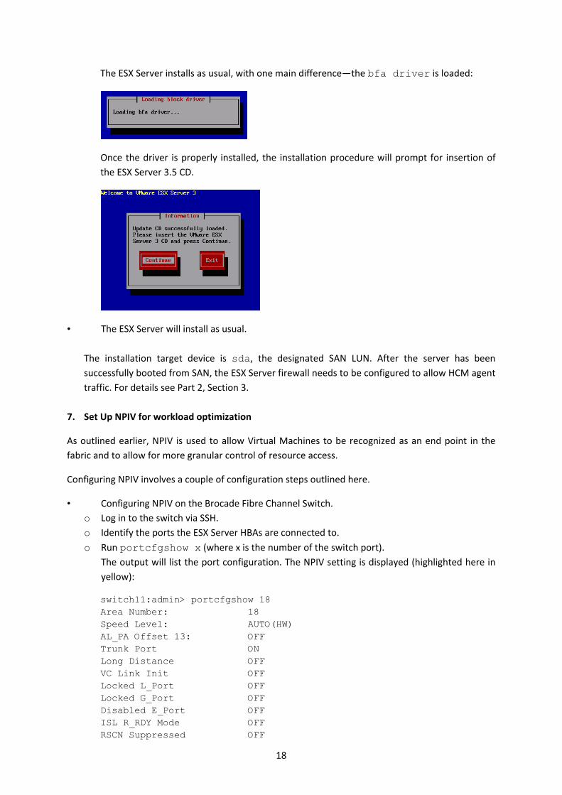
The ESX Server installs as usual, with one main difference—the bfa driver is loaded:
Once the driver is properly installed, the installation procedure will prompt for insertion of
the ESX Server 3.5 CD.
• The ESX Server will install as usual.
The installation target device is sda, the designated SAN LUN. After the server has been successfully booted from SAN, the ESX Server firewall needs to be configured to allow HCM agent
traffic. For details see Part 2, Section 3.
7. Set Up NPIV for workload optimization
As outlined earlier, NPIV is used to allow Virtual Machines to be recognized as an end point in the
fabric and to allow for more granular control of resource access.
Configuring NPIV involves a couple of configuration steps outlined here.
• Configuring NPIV on the Brocade Fibre Channel Switch.
o Log in to the switch via SSH.
o Identify the ports the ESX Server HBAs are connected to.
o Run portcfgshow x (where x is the number of the switch port).
The output will list the port configuration. The NPIV setting is displayed (highlighted here in
yellow):
switch11:admin> portcfgshow 18 Area Number: 18 Speed Level: AUTO(HW) AL_PA Offset 13: OFF Trunk Port ON Long Distance OFF VC Link Init OFF Locked L_Port OFF Locked G_Port OFF Disabled E_Port OFF ISL R_RDY Mode OFF RSCN Suppressed OFF
18
Persistent Disable OFF NPIV capability ON QOS E_Port ON Port Auto Disable: OFF Rate Limit OFF EX Port OFF Mirror Port OFF Credit Recovery ON F_Port Buffers OFF
o In case NPIV is OFF, NPIV can be enabled with the following command:
portCfgNPIV <port number> 1 o NPIV can be disabled with the following command:
portCfgNPIV <port number> 0
• Identifying HBAs in the ESX Server
Login to the ESX Server via SSH with root privileges.
Identify the HBAs.
[root@esx-brocade-dell root]# ls /proc/scsi ata_piix bfa mptscsih scsi sg vsa0
The Brocade HBA is listed as bfa. Determine the instance number or numbers is the next step.
[root@esx-brocade-dell root]# ls /proc/scsi/bfa 4 5 HbaApiNode
A quick check for each instance reveals type and connectivity status of each instance (port)
[root@esx-brocade-dell root]# cat /proc/scsi/bfa/4 Chip Revision: Rev-C Manufacturer: Brocade Model Description: Brocade-825 Instance Num: 0 Serial Num: ALX0441D07H Firmware Version: FCHBA1.1.0 Hardware Version: Rev-C Bios Version: Optrom Version: Port Count: 2 WWNN: 20:00:00:05:1e:61:67:61 WWPN: 10:00:00:05:1e:61:67:61 Instance num: 0 Target ID: 0 WWPN: 50:06:01:61:3c:e0:1e:e1 Target ID: 1 WWPN: 50:06:01:69:3c:e0:1e:e1 Target ID: 2 WWPN: 50:01:43:80:02:5b:25:0c Target ID: 3 WWPN: 50:01:43:80:02:5b:25:0d
[root@esx-brocade-dell root]# cat /proc/scsi/bfa/5 Chip Revision: Rev-C Manufacturer: Brocade Model Description: Brocade-825 Instance Num: 1
19
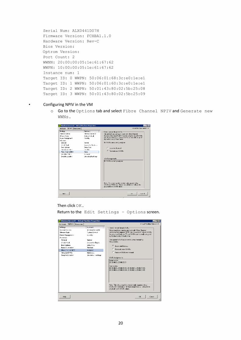
Serial Num: ALX0441D07H Firmware Version: FCHBA1.1.0 Hardware Version: Rev-C Bios Version: Optrom Version: Port Count: 2 WWNN: 20:00:00:05:1e:61:67:62 WWPN: 10:00:00:05:1e:61:67:62 Instance num: 1 Target ID: 0 WWPN: 50:06:01:68:3c:e0:1e:e1 Target ID: 1 WWPN: 50:06:01:60:3c:e0:1e:e1 Target ID: 2 WWPN: 50:01:43:80:02:5b:25:08 Target ID: 3 WWPN: 50:01:43:80:02:5b:25:09
• Configuring NPIV in the VM
o Go to the Options tab and select Fibre Channel NPIV and Generate new WWNs.
Then click OK.
Return to the Edit Settings – Options screen.
20
Verify the creation of Node and Port WWNs. Every Virtual Machine that is
successfully NPIV enabled has a Node WWN and Port WWN combination, also
referred to a Vport. Those entries are unique and maintained by the ESX Server/VC.
To enable multipathing, the ESX Server automatically creates up to four Port WWNs
for an individual VM.
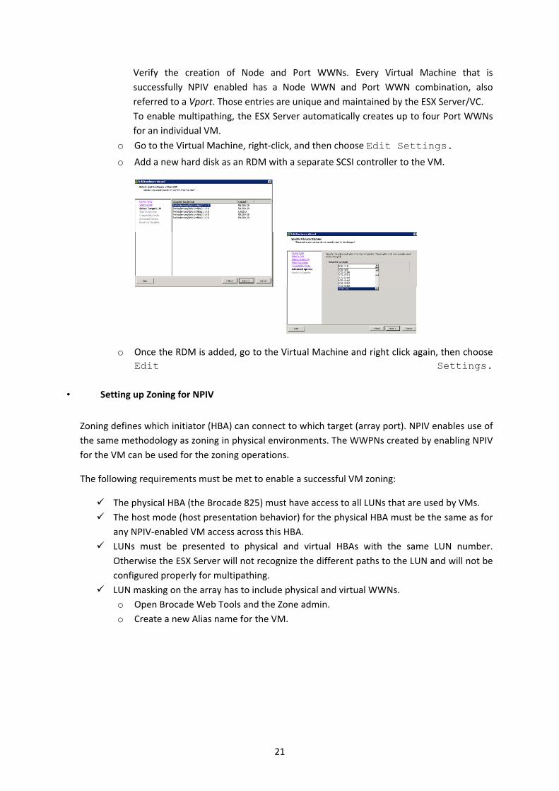
o Go to the Virtual Machine, right‐click, and then choose Edit Settings.
o Add a new hard disk as an RDM with a separate SCSI controller to the VM.
o Once the RDM is added, go to the Virtual Machine and right click again, then choose
Edit Settings.
• Setting up Zoning for NPIV
Zoning defines which initiator (HBA) can connect to which target (array port). NPIV enables use of
the same methodology as zoning in physical environments. The WWPNs created by enabling NPIV
for the VM can be used for the zoning operations.
The following requirements must be met to enable a successful VM zoning:
The physical HBA (the Brocade 825) must have access to all LUNs that are used by VMs.
The host mode (host presentation behavior) for the physical HBA must be the same as for
any NPIV‐enabled VM access across this HBA.
LUNs must be presented to physical and virtual HBAs with the same LUN number.
Otherwise the ESX Server will not recognize the different paths to the LUN and will not be
configured properly for multipathing.
LUN masking on the array has to include physical and virtual WWNs.
o Open Brocade Web Tools and the Zone admin.
o Create a new Alias name for the VM.
21
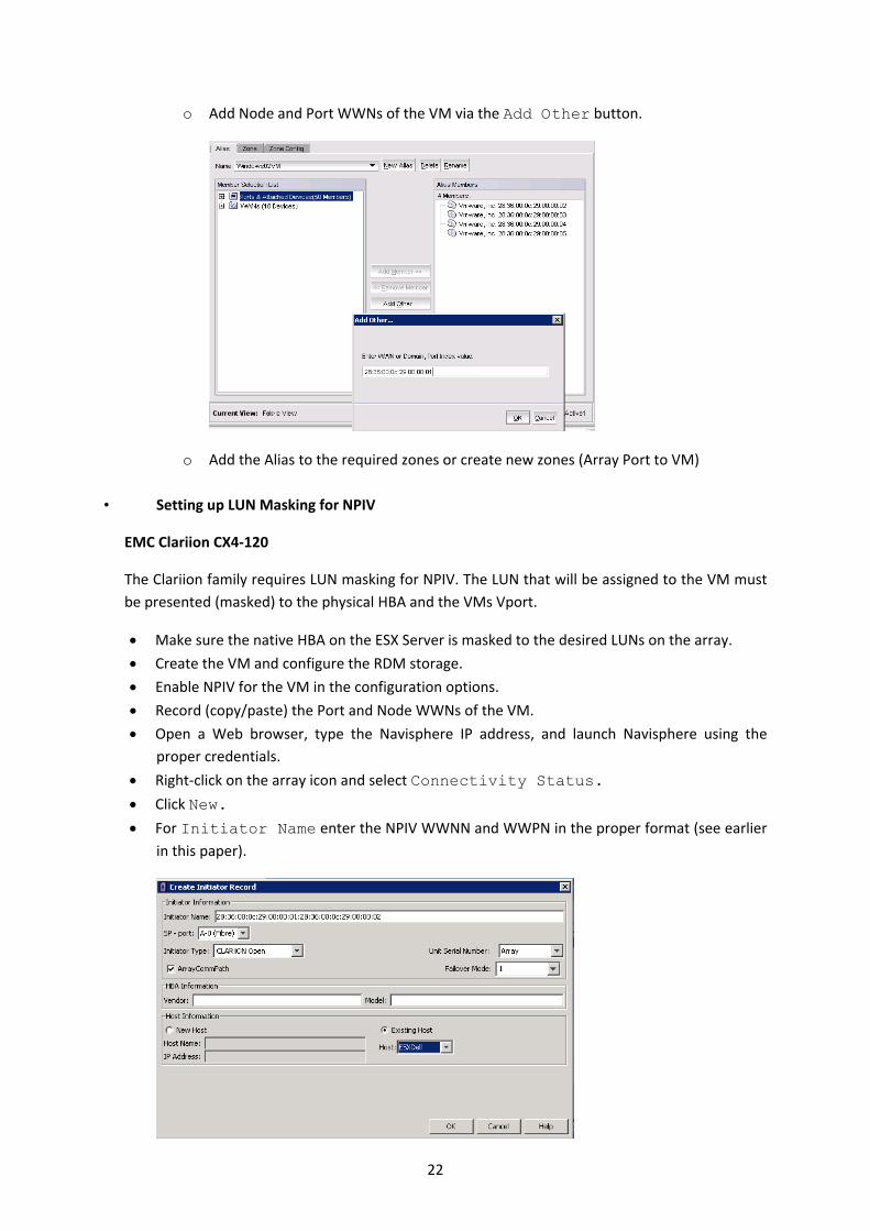
o Add Node and Port WWNs of the VM via the Add Other button.
o Add the Alias to the required zones or create new zones (Array Port to VM)
• Setting up LUN Masking for NPIV
EMC Clariion CX4‐120
The Clariion family requires LUN masking for NPIV. The LUN that will be assigned to the VM must
be presented (masked) to the physical HBA and the VMs Vport.
Make sure the native HBA on the ESX Server is masked to the desired LUNs on the array.
Create the VM and configure the RDM storage.
Enable NPIV for the VM in the configuration options.
Record (copy/paste) the Port and Node WWNs of the VM.
Open a Web browser, type the Navisphere IP address, and launch Navisphere using the
proper credentials.
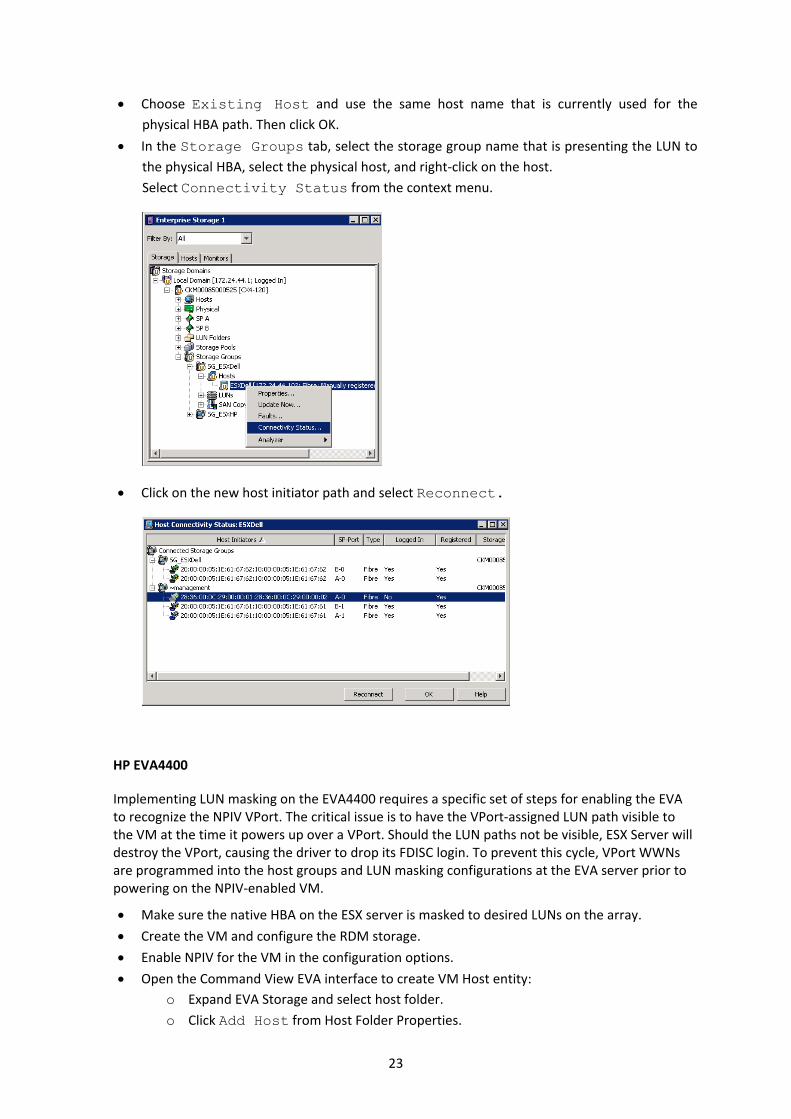
Right‐click on the array icon and select Connectivity Status.
Click New.
For Initiator Name enter the NPIV WWNN and WWPN in the proper format (see earlier
in this paper).
22
Choose Existing Host and use the same host name that is currently used for the
physical HBA path. Then click OK.
In the Storage Groups tab, select the storage group name that is presenting the LUN to
the physical HBA, select the physical host, and right‐click on the host.
Select Connectivity Status from the context menu.
Click on the new host initiator path and select Reconnect.
HP EVA4400
Implementing LUN masking on the EVA4400 requires a specific set of steps for enabling the EVA to recognize the NPIV VPort. The critical issue is to have the VPort‐assigned LUN path visible to the VM at the time it powers up over a VPort. Should the LUN paths not be visible, ESX Server will destroy the VPort, causing the driver to drop its FDISC login. To prevent this cycle, VPort WWNs are programmed into the host groups and LUN masking configurations at the EVA server prior to powering on the NPIV‐enabled VM.
Make sure the native HBA on the ESX server is masked to desired LUNs on the array.
Create the VM and configure the RDM storage.
Enable NPIV for the VM in the configuration options.
Open the Command View EVA interface to create VM Host entity:
o Expand EVA Storage and select host folder.
o Click Add Host from Host Folder Properties.
23
o Enter the VM host name and enter the NPIV WWPN.
o Click Add host. o Repeat if multiple WWPN are assigned to the VM.
Storage presentation using the command view EVA:
o In the Virtual Disks folder, use the virtual disk that was associated to the VM.
o Select the disk and the select the Presentation tab.
o Click the Present button and select the newly created VM host entry.
o Click Assign LUN and select exactly the LUN number that was also presented to
the physical HBA.
o Select Save Changes to enable the newly configured presentation.
8. Streamline workloads with QoS in an 8 Gbps infrastructure – QoS setup
NPIV is used to present dedicated LUNs into VMs via Raw Device Mapping. NPIV enables the
isolation of traffic into dedicated zones and the separation of those zones from each other. And
Quality of Service (QoS) takes workload optimization even one step further.
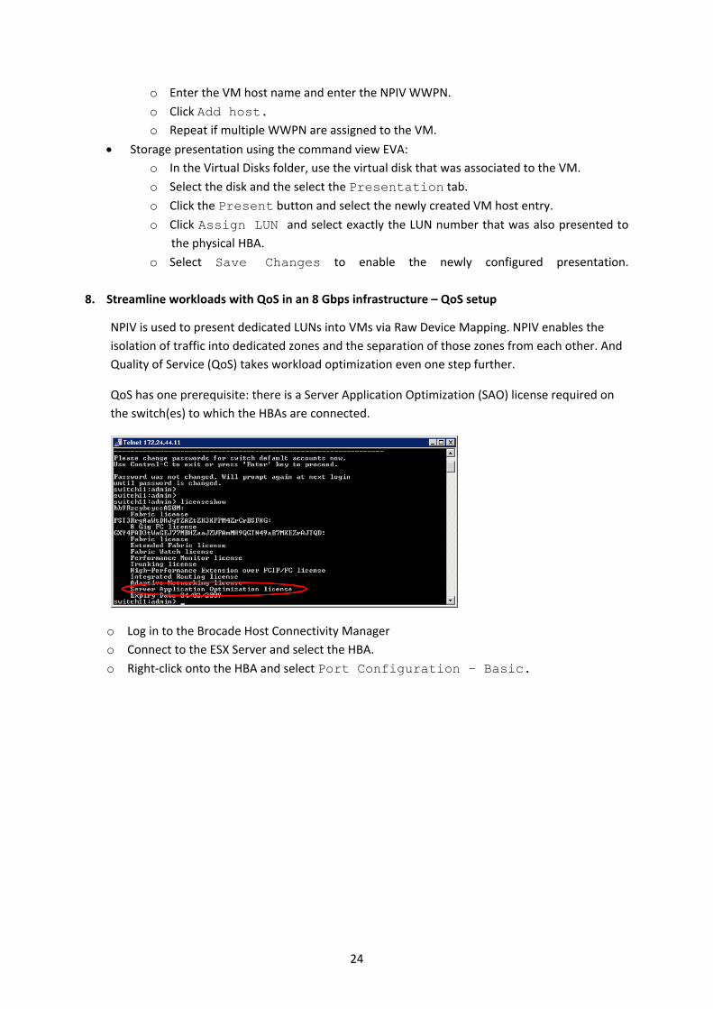
QoS has one prerequisite: there is a Server Application Optimization (SAO) license required on
the switch(es) to which the HBAs are connected.
o Log in to the Brocade Host Connectivity Manager
o Connect to the ESX Server and select the HBA.
o Right‐click onto the HBA and select Port Configuration – Basic.
24

o In the Port Configuration dialog box, enable QoS.
o Once the port is QoS enabled, the QoS status is reflected in the port properties, also showing
the available prioritization levels.
25
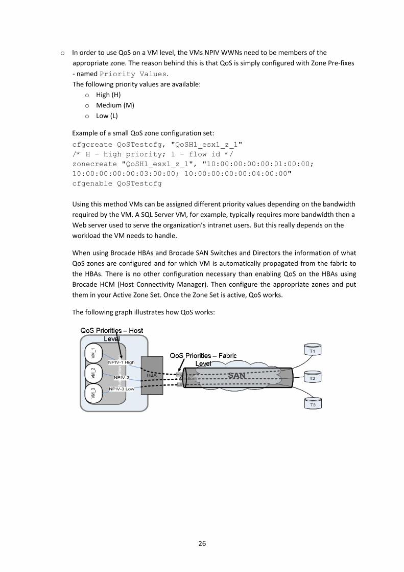
o In order to use QoS on a VM level, the VMs NPIV WWNs need to be members of the
appropriate zone. The reason behind this is that QoS is simply configured with Zone Pre‐fixes
‐ named Priority Values. The following priority values are available:
o High (H)
o Medium (M)
o Low (L)
Example of a small QoS zone configuration set:
cfgcreate QoSTestcfg, "QoSH1_esx1_z_1" /* H – high priority; 1 – flow id */ zonecreate "QoSH1_esx1_z_1", "10:00:00:00:00:01:00:00; 10:00:00:00:00:03:00:00; 10:00:00:00:00:04:00:00" cfgenable QoSTestcfg
Using this method VMs can be assigned different priority values depending on the bandwidth
required by the VM. A SQL Server VM, for example, typically requires more bandwidth then a
Web server used to serve the organization’s intranet users. But this really depends on the
workload the VM needs to handle.
When using Brocade HBAs and Brocade SAN Switches and Directors the information of what
QoS zones are configured and for which VM is automatically propagated from the fabric to
the HBAs. There is no other configuration necessary than enabling QoS on the HBAs using
Brocade HCM (Host Connectivity Manager). Then configure the appropriate zones and put
them in your Active Zone Set. Once the Zone Set is active, QoS works.
The following graph illustrates how QoS works:
26
27
Summary and Conclusion
Server virtualization offers quite a few benefits. The downside of server virtualization is Virtual
Machine sprawl, usually resulting in a large number of Virtual Machines (and application workloads
inside the VMs) running in parallel. These VMs usually also share a common storage environment.
As a result, storage performance can become an issue sooner or later.
N_Port Virtualization (NPIV) is one approach to presenting storage LUN directly to Virtual Machines,
and making the storage environment “VM‐aware”. Combining Brocade 8 Gbps Switches and Brocade
8 Gbps HBAs with the ESX Server´s NPIV capabilities allows for efficient performance management.
NPIV plays an important role by assigning WWNs directly to Virtual Machines, thus enabling Zoning
and LUN masking setup directly on Virtual Machines running on the ESX Server.
The Brocade 815/825 HBAs with the 8 Gbps technology are the foundation for providing the correct
bandwidth for larger numbers of VMs in parallel while supporting NPIV. Beyond NPIV, Brocade HBAs
and Switches allow for additional bandwidth management using QoS (Quality of Service).
The Brocade QoS implementation features an intelligent zoning setup to prioritize and deprioritize
workloads from the VM through to the storage device, therefore enabling high performance (highly
prioritized) Microsoft Exchange, SQL Server, or backup implementations in a virtualized environment.
Brocade, the B‐wing symbol, BigIron, DCX, Fabric OS, FastIron, IronPoint, IronShield, IronView, IronWare, JetCore, NetIron,
SecureIron, ServerIron, StorageX, and TurboIron are registered trademarks, and DCFM and SAN Health are trademarks of Brocade
Communications Systems, Inc., in the United States and/or in other countries. All other brands, products, or service names are or
may be trademarks or service marks of, and are used to identify, products or services of their respective owners..