deploying microsoft windows server 2008 and vista on a ...€¦ · deploying microsoft windows...
TRANSCRIPT

© 2007 Cisco Systems, Inc. All rights reserved. Cisco Public 1
Deploying Microsoft Windows Server 2008 and Vista on a Cisco Network
Updated: 9/30/08

© 2007 Cisco Systems, Inc. All rights reserved. Cisco Public 2
Agenda
Microsoft Windows Server 2008 and Windows Vista Network Overview
IPv6 in Windows Server 2008 and Windows Vista
Cisco Branch Network Impact - WAAS
Cisco Data Center Network / Application Services Impact
TCP Interoperability with Cisco ACE
Windows Server 2008 Failover Clusters @ Layer 3
© 2007 Cisco Systems, Inc. All rights reserved. Cisco Public 3
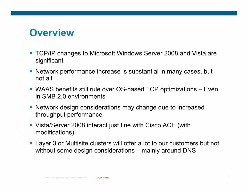
Overview
TCP/IP changes to Microsoft Windows Server 2008 and Vista are significant
Network performance increase is substantial in many cases, but not all
WAAS benefits still rule over OS-based TCP optimizations – Even in SMB 2.0 environments
Network design considerations may change due to increased throughput performance
Vista/Server 2008 interact just fine with Cisco ACE (with modifications)
Layer 3 or Multisite clusters will offer a lot to our customers but not without some design considerations – mainly around DNS

© 2007 Cisco Systems, Inc. All rights reserved. Cisco Public 4
Microsoft Windows Server 2008 and Vista Network Overview

© 2007 Cisco Systems, Inc. All rights reserved. Cisco Public 5
TCP/IP Stack Features http://technet.microsoft.com/en-us/library/bb726965.aspx IPv6 enabled by default and preferred Receive Window Auto-Tuning Compound TCP – Applicable in High BW/High Delay networks Enhancements for high-loss environments – RFC-based improvements for
WLAN environments Neighbor Unreachability Detection for IPv4 – Equivalent to NUD for IPv6.
Not applicable or beneficial in networks with real first hop routing protocol (HSRP/GLBP).
Receive-Side Scaling – balance TCP flows across multiple CPUs (See findings from Maurizio Portolani/Christian Elsen EDCS:699210)
Changes in dead gateway detection – Fail-back support has been added Changes to PMTU black hole router detection - http://tinyurl.com/677skq Network Diagnostics Framework support TCP extended statistics (ESTATS) – TCP Analyzer program (obtain via
Vista SDK) Windows Filtering Platform Explicit Congestion Notification – Allows host to adjust TCP based on
ECN notification from routers (IOS supports ECN notification as does Catalyst 4500)

© 2007 Cisco Systems, Inc. All rights reserved. Cisco Public 6
Enhanced Capabilities Of 2008/Vista
Receive Window Auto-Tuning ECN Support
Per application auto-scaled window (network buffer) size
Aggressive send window growth based on delay and loss (more aggressive on high delay connections after loss to quickly bring window size back up to optimal level
IPv6 is preferred over IPv4
Recognizes and controls data transfers based on network congestion being flagged
Compound TCP IPv6
Congestion flagged packets
IPv6 NA/DHCPv6? ISATAP Router?
Teredo Server? Fallback to IPv4?

© 2007 Cisco Systems, Inc. All rights reserved. Cisco Public 7
Standard TCP FTP to client
Max Rcv Window Size (default max 64KB)
TCP Send Window Size
TCP Negotiation/Setup
(including rcv window size)
Current window
Send first segment
Initial Connection Setup
Acknowledgement/current rcv window free size
Increase current send window by 1 segment
per acknowledgement
Send next segments
Partial acknowledgement/current rcv window free size (some packets lost)
Halve send window
Resend segments
Slow start
Congestion Management
Current Rcv Window Size
App retrieves data from window
App retrieves data from window
App retrieves data from window

© 2007 Cisco Systems, Inc. All rights reserved. Cisco Public 8
Vista/2008 TCP FTP to client
Max Rcv Window Size (with scaling max 1GB)
TCP Send Window Size
TCP Negotiation/Setup
(optional scaling of rcv window size up to 1GB –
RFC1323) Current window
Send first segment
Initial Connection Setup (with Window Auto-tuning and RFC1323)
X segments acknowledged/current rcv window free size
Increase current send window by X segments (with even more aggressive increases for large
rcv window size and BDP connections)
Send next segments
Partial acknowledgement for x segments (some packets lost or ECN marked)
Reduce send window to x segments
Resend segments
Slow start (with Window Auto-tuning and CTCP)
Congestion Management (with CTCP and ECN Support)
Current Rcv Window Size (auto tuned based on delay
and app retrieve rate)
App retrieves data from window
App retrieves data from window
App retrieves data from window

© 2007 Cisco Systems, Inc. All rights reserved. Cisco Public 9
XP/2003 – Stack Behavior Review
XP/2003 default TCP window size is 65535
Sender’s TX rate is limited by advertised RX window
Window size backs off by 50% with packet loss
Increases window size by one for every successful ACK
Manual tuning of RX window size is often suboptimal (takes for all apps on all links)
MSFT-Stack-Overview Todd Thorson - MSFT

© 2007 Cisco Systems, Inc. All rights reserved. Cisco Public 10
Microsoft Windows Server 2008/Vista Auto-tuning
Flows may congest available WAN BW
On by default
Adjusts EACH TCP flow over time
Increase throughput for long latency flows
Auto-tuning automatically senses TCP environment to determine optimal window size
RTT
Application consumption capacity (some apps may not yield any performance improvements)
MSFT-Stack-Overview Todd Thorson - MSFT

© 2007 Cisco Systems, Inc. All rights reserved. Cisco Public 11
Can be changed via GPO or CLI netsh interface tcp set global autotuninglevel =
disabled – scaling is turned off – XP-like performance (64-KB window)
highlyrestricted – scaling limited to 2 (256 KB window)
restricted – scaling is limited to 4 (1 MB window)
normal (default on Vista) – scaling is limited to 8 (16 MB window)
experimental (unlimited) – scaling up to 14 (1 GB window)
Application can alter scaling value – Window Vista with IE7 and Firefox use “highlyrestricted”
Microsoft Windows Server 2008/Vista Auto-tuning Parameters
Window scale: 2 (multiply by 4)

© 2007 Cisco Systems, Inc. All rights reserved. Cisco Public 12
During some tests TCP Window sizes were as high as 7 Meg
The large window sizes can cause issues such as out-of-order segment errors
Negotiated TCP Window Size Examples
2053 51.46 10.6.1.1 10.6.1.2 TCP 63050 > http [ACK] Seq=132 Ack=633613893 Win=5058816 Len=0

© 2007 Cisco Systems, Inc. All rights reserved. Cisco Public 13
More aggressive in increasing the send window for high BW, high latency flows
Maximizes throughput by monitoring variations in delay and loss
Works in conjunction with auto-tuning to improve performance
Off by default on Vista and on by default on Server 2008
netsh interface tcp set global congestionprovider =
none – CTCP is disabled
ctcp – CTCP is enabled
Microsoft Windows Server 2008/Vista Compound TCP (CTCP)

© 2007 Cisco Systems, Inc. All rights reserved. Cisco Public 14
ECN - Summary
ECN is off by default in Microsoft Vista/Server 2008 due to possible support issues in legacy routers/firewalls where ECN flags are not supported
Can be enabled/disabled by using netsh int tcp set global ecncapability=enabled Microsoft Vista/Server 2008 will have TCP backoff when ECN ECN-CE is set to “1”
If “middle box” can support ECN, congestion could be better controlled from the endpoint by the OS participating in congestion control
Middle boxes should support ECN so that packets with these flags set by other devices (endpoints, routers) can at least forward the packets even if they do not support setting the ECN flags when congestion is present
Allows for Endpoint to help with congestion issues in the network – WRED can be used to mark traffic for ECN handling that would otherwise be a candidate for drop
At this time ECN should be avoided ECN usages on the host nodes demonstrates erratic drops and rapid recovery at times and other times offers no change at all Standard WRED is the recommended method to achieve the original goal of ECN (as it pertains to the host)

© 2007 Cisco Systems, Inc. All rights reserved. Cisco Public 15
ECN IOS Example policy-map ECN class class-default bandwidth percent 100 random-detect random-detect ecn policy-map MQC-SHAPING-5MBPS class class-default shape average 4750000 47500 0 service-policy ECN ! interface FastEthernet0/0 ip address 10.1.1.1 255.255.255.0 service-policy output MQC-SHAPING-5MBPS
Microsoft Vista ECN enabled
10.1.2.4
Router with ECN enabled
Microsoft Server 2008 ECN enabled
10.1.1.3
#show policy-map interface f0/0 …OUTPUT SUMMARIZED FOR CLARITY Service-policy output: MQC-SHAPING-5MBPS
Class-map: class-default (match-any) exponential weight: 9
explicit congestion notification mean queue depth: 19
class ECN Mark pkts/bytes 0 171/257053 1 0/0
F0/0 F0/1

© 2007 Cisco Systems, Inc. All rights reserved. Cisco Public 16
ECN – View of a Packet
Internet Protocol, Src: 10.1.2.4 (10.1.2.4), Dst: 10.1.1.3 (10.1.1.3) Version: 4 Header length: 20 bytes Differentiated Services Field: 0x02 (DSCP 0x00: Default; ECN: 0x02) 0000 00.. = Differentiated Services Codepoint: Default (0x00) .... ..1. = ECN-Capable Transport (ECT): 1 .... ...0 = ECN-CE: 0
Internet Protocol, Src: 10.1.1.3 (10.1.1.3), Dst: 10.1.2.4 (10.1.2.4) Version: 4 Header length: 20 bytes Differentiated Services Field: 0x03 (DSCP 0x00: Default; ECN: 0x03) 0000 00.. = Differentiated Services Codepoint: Default (0x00) .... ..1. = ECN-Capable Transport (ECT): 1 .... ...1 = ECN-CE: 1
Endpoints are ECN capable – ECT set to 1
Congestion experienced by router – ECN-CE set to 1
© 2007 Cisco Systems, Inc. All rights reserved. Cisco Public 17
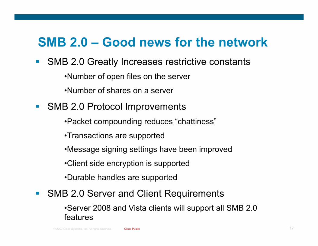
SMB 2.0 Greatly Increases restrictive constants • Number of open files on the server
• Number of shares on a server
SMB 2.0 Protocol Improvements • Packet compounding reduces “chattiness”
• Transactions are supported
• Message signing settings have been improved
• Client side encryption is supported
• Durable handles are supported
SMB 2.0 Server and Client Requirements • Server 2008 and Vista clients will support all SMB 2.0 features
SMB 2.0 – Good news for the network

© 2007 Cisco Systems, Inc. All rights reserved. Cisco Public 18
SMB 1.0 Negotiation XP to 2008 or Vista to 2003
No. Time Source Destination Protocol Info 134 21.925052 10.124.2.18 10.121.10.14 SMB Negotiate Protocol Request … Transmission Control Protocol, Src Port: can-ferret (1920), Dst Port: microsoft-ds (445), Seq: 687977853, Ack: 2938559479, Len: 137 NetBIOS Session Service SMB (Server Message Block Protocol) SMB Header Negotiate Protocol Request (0x72) Word Count (WCT): 0 Byte Count (BCC): 98 Requested Dialects Dialect: PC NETWORK PROGRAM 1.0 Dialect: LANMAN1.0 Dialect: Windows for Workgroups 3.1a Dialect: LM1.2X002 Dialect: LANMAN2.1 Dialect: NT LM 0.12
No. Time Source Destination Protocol Info 135 21.925724 10.121.10.14 10.124.2.18 SMB Negotiate Protocol Response … Transmission Control Protocol, Src Port: microsoft-ds (445), Dst Port: can-ferret (1920), Seq: 2938559479, Ack: 687977990, Len: 197 NetBIOS Session Service SMB (Server Message Block Protocol) SMB Header Negotiate Protocol Response (0x72) Word Count (WCT): 17 Dialect Index: 5, greater than LANMAN2.1 Security Mode: 0x03 Max Mpx Count: 50 Max VCs: 1 Max Buffer Size: 16644 Max Raw Buffer: 65536 ….

© 2007 Cisco Systems, Inc. All rights reserved. Cisco Public 19
SMB 2.0 Negotiation Vista/2008 Only
No. Time Source Destination Protocol Info 161 29.340781 10.124.2.5 10.121.10.14 SMB Negotiate Protocol Request … Transmission Control Protocol, Src Port: 49396 (49396), Dst Port: microsoft-ds (445), Seq: 2713220216, Ack: 4127120, Len: 148 NetBIOS Session Service SMB (Server Message Block Protocol) SMB Header Negotiate Protocol Request (0x72) Word Count (WCT): 0 Byte Count (BCC): 109 Requested Dialects Dialect: PC NETWORK PROGRAM 1.0 Dialect: LANMAN1.0 Dialect: Windows for Workgroups 3.1a Dialect: LM1.2X002 Dialect: LANMAN2.1 Dialect: NT LM 0.12 Dialect: SMB 2.002
No. Time Source Destination Protocol Info 162 29.341902 10.121.10.14 10.124.2.5 SMB2 NegotiateProtocol Response … Transmission Control Protocol, Src Port: microsoft-ds (445), Dst Port: 49396 (49396), Seq: 14127120, Ack: 2713220364, Len: 240 NetBIOS Session Service SMB2 (Server Message Block Protocol version 2) SMB2 Header Server Component: SMB2 Header Length: 64 NT Status: STATUS_SUCCESS (0x00000000) Command: NegotiateProtocol (0) unknown: 0100 Flags: 0x00000001 Chain Offset: 0x00000000 Command Sequence Number: 0 …

© 2007 Cisco Systems, Inc. All rights reserved. Cisco Public 20
Roles AD Domain Services – ADDS
AD Lightweight Directory Service – ADLDS
Domain Name System Server - DNS
Dynamic Host Configuration Protocol Server – DHCP
File Services
Print Server
Streaming Media Services
Internet Information Services (IIS7)
Windows Server Virtualization – WSV (available within 180 days of RTM)
Features BitLocker
Client For NFS
DFS Server & Replication
Failover Cluster
FRS
LPD Print Service
MultipathIO
Network Load Balancing
Removable Storage Management
Server For NFS
SNMP
Subsystem for UNIX-based Applications
Telnet Client
Windows Server Backup
WINS
Server Core – Feature Summary

© 2007 Cisco Systems, Inc. All rights reserved. Cisco Public 21
Branch Office Deployments Will the customer remove remote servers?
Restart Active Directory without rebooting
Can be done through command line and MMC
Can’t boot the DC to stopped mode of Active Directory
No effect on non-related services while restarting Active Directory
Several ways to process login under stopped mode
RoDC – Read-only Domain Controller Uni-directional Replication
Credential Caching
Server Core
TCP Window Auto-tuning and CTCP offer basic network BW optimization – sort of

© 2007 Cisco Systems, Inc. All rights reserved. Cisco Public 22
IPv6 in Vista/W2K8
http://www.microsoft.com/technet/network/ipv6/default.mspx

© 2007 Cisco Systems, Inc. All rights reserved. Cisco Public 23
Understand The Behavior Of Vista
IPv6 is preferred over IPv4 – Vista sends IPv6 NA/NS/RS upon link-up
– Attempts DHCP for IPv6
– If no DHCP or local RA received with Global or ULA, then try ISATAP
– If no ISATAP, then try Teredo
Become familiar with Teredo
http://www.microsoft.com/technet/prodtechnol/winxppro/maintain/teredo.mspx
ANY application built on the Peer-to-Peer Framework REQUIRES IPv6 and will NOT function over IPv4 - http://www.microsoft.com/technet/network/p2p/default.mspx

© 2007 Cisco Systems, Inc. All rights reserved. Cisco Public 24
In More Detail – Vista on link-up No Network Services
1. Unspecified address :: -> Solicited node address NS/DAD 2. Looking for a local router -> ff02::2 RS
3. Looking for MLD enabled routers -> ff02::16 MLDv2 report 4. LLMNR for IPv6 – ff02::1:3 – advertise hostname 5. LLMNR for IPv4 – 224.0.0.252 from RFC 3927 address 6. No global or ULA received via step 1/2 – Try ISATAP 7. Try DHCP for IPv6 – ff02::1:2 8. Try DHCP for IPv4
No. Time Source Destination Protocol Info 1 0.000000 :: ff02::1:ffae:4361 ICMPv6 Neighbor solicitation 2 0.000030 fe80::80aa:fd5:f7ae:4361 ff02::2 ICMPv6 Router solicitation 3 0.000080 fe80::80aa:fd5:f7ae:4361 ff02::16 ICMPv6 Multicast Listener Report Message v2 4 1.155917 fe80::80aa:fd5:f7ae:4361 ff02::1:3 UDP Source port: 49722 Destination port: 5355 5 1.156683 169.254.67.97 224.0.0.252 UDP Source port: 49723 Destination port: 5355 6 3.484709 169.254.67.97 169.254.255.255 NBNS Name query NB ISATAP<00> 7 126.409530 fe80::80aa:fd5:f7ae:4361 ff02::1:2 DHCPv6 Information-request 8 128.886397 0.0.0.0 255.255.255.255 DHCP DHCP Discover - Transaction ID 0x6c8d6efa
fe80::80aa:fd5:f7ae:4361 ese-vista1

© 2007 Cisco Systems, Inc. All rights reserved. Cisco Public 25
IPv4 Network – No IPv6 Network Services What Does Vista Try To Do?
No. Time Source Destination Protocol Info 13 8.813509 10.120.2.1 10.120.2.2 DHCP DHCP ACK - Transaction ID 0x2b8af443 .... Bootstrap Protocol ... Your (client) IP address: 10.120.2.2 (10.120.2.2) ... Option: (t=3,l=4) Router = 10.120.2.1 Option: (t=6,l=4) Domain Name Server = 10.121.11.4 Option: (t=15,l=9) Domain Name = "cisco.com" ..
No. Time Source Destination Protocol Info 70 13.360756 10.120.2.2 10.121.11.4 DNS Standard query A isatap.cisco.com
No. Time Source Destination Protocol Info 138 25.362181 10.120.2.2 10.121.11.4 DNS Standard query A teredo.ipv6.microsoft.com
No. Time Source Destination Protocol Info 580 296.686197 10.120.2.2 10.120.3.2 TCP 49211 > epmap [SYN] Seq=0 Len=0 MSS=1460 WS=8 581 296.687721 10.120.3.2 10.120.2.2 TCP epmap > 49211 [SYN, ACK] Seq=0 Ack=1 Win=2097152 582 296.687794 10.120.2.2 10.120.3.2 TCP 49211 > epmap [ACK] Seq=1 Ack=1 Win=65536 Len=0 583 296.687913 10.120.2.2 10.120.3.2 DCERPC Bind: call_id: 1, 2 context items, 1st IOXIDResolver V0.0
10.120.2.2 ese-vista1
10.120.3.2 ese-vista2
ISATAP??
Teredo??
IPv4-only Router

© 2007 Cisco Systems, Inc. All rights reserved. Cisco Public 26
Client Configuration - Dual-Stack Required
Microsoft Windows XP (SP1 or higher), Server 2003, Vista, Server 2008
IPv6 must be installed on XP/2003 (enabled by default on Vista/Server 2008) C:\>ipv6 install
Have network (Routers/Switches) configured for IPv6 Stateless autoconfiguration and/or DHCPv6
C:\>ipconfig
Windows IP Configuration
Ethernet adapter Local Area Connection 1: Connection-specific DNS Suffix . : IP Address. . . . . . . . . . . . : 10.1.1.100 Subnet Mask . . . . . . . . . . . : 255.255.255.0 IP Address. . . . . . . . . . . . : 2001:db8:cafe:1122:203:ffff:fe81:d6da IP Address. . . . . . . . . . . . : fe80::203:ffff:fe81:d6da%4 Default Gateway . . . . . . . . . : 10.1.1.1
fe80::201:42ff:fe2d:9580
Dual-stack Router Windows Client
© 2007 Cisco Systems, Inc. All rights reserved. Cisco Public 27
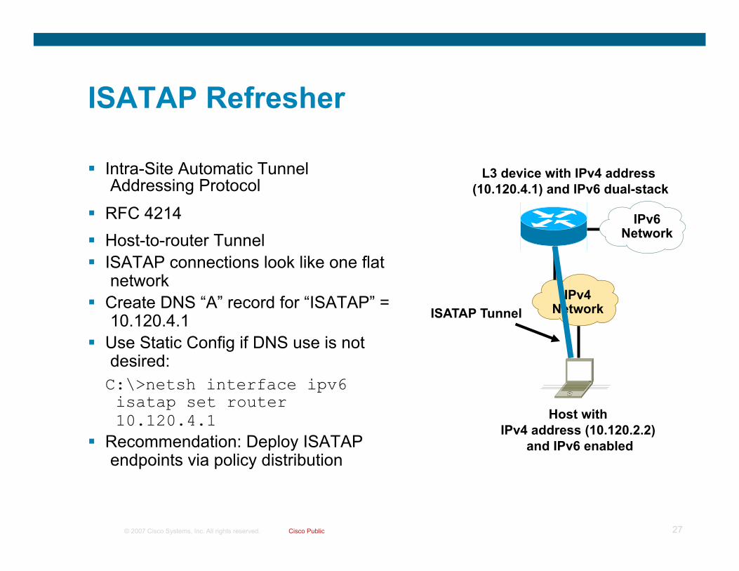
ISATAP Refresher
Intra-Site Automatic Tunnel Addressing Protocol
RFC 4214 Host-to-router Tunnel ISATAP connections look like one flat
network Create DNS “A” record for “ISATAP” =
10.120.4.1 Use Static Config if DNS use is not
desired: C:\>netsh interface ipv6 isatap set router 10.120.4.1
Recommendation: Deploy ISATAP endpoints via policy distribution
IPv4 Network
Host with IPv4 address (10.120.2.2)
and IPv6 enabled
L3 device with IPv4 address (10.120.4.1) and IPv6 dual-stack
IPv6 Network
ISATAP Tunnel

© 2007 Cisco Systems, Inc. All rights reserved. Cisco Public 28
IPv4 Network – ISATAP Enabled Router No. Time Source Destination Protocol Info 302 48.129716 fe80::5efe:a78:202 fe80::5efe:a78:401 ICMPv6 Router solicitation Internet Protocol, Src: 10.120.2.2 (10.120.2.2), Dst: 10.120.4.1 (10.120.4.1)
No. Time Source Destination Protocol Info 871 480.607899 fe80::5efe:a78:401 fe80::5efe:a78:202 ICMPv6 Router advertisement Internet Protocol, Src: 10.120.4.1 (10.120.4.1), Dst: 10.120.2.2 (10.120.2.2)
No. Time Source Destination Protocol Info 1235 675.685012 2001:db8:cafe:1010:0:5efe:a78:302 2001:db8:cafe:1010:0:5efe:a78:202 ICMPv6 Echo request Internet Protocol, Src: 10.120.3.2 (10.120.3.2), Dst: 10.120.2.2 (10.120.2.2)
No. Time Source Destination Protocol Info 1236 675.685259 2001:db8:cafe:1010:0:5efe:a78:202 2001:db8:cafe:1010:0:5efe:a78:302 ICMPv6 Echo reply Internet Protocol, Src: 10.120.2.2 (10.120.2.2), Dst: 10.120.3.2 (10.120.3.2)
10.120.2.2 fe80::5efe:a78:202
2001:DB8:CAFE:1010:5EFE:A78:202 ese-vista1
10.120.3.2 fe80::5efe:a78:302
2001:DB8:CAFE:1010:5EFE:A78:302 ese-vista2
ISATAP Tunnel 10.120.4.1 fe80::5efe:a78:401
2001:DB8:CAFE:1010::/64 ISATAP router
ISATAP Tunnel

© 2007 Cisco Systems, Inc. All rights reserved. Cisco Public 29
Client Configuration - ISATAP
Windows Vista will automatically attempt to resolve the name “ISATAP”
Local host name
Hosts file - SystemRoot\system32\drivers\etc
DNS name query (“A” record)
NetBIOS and Lmhosts
Manual ISATAP router entry can be made netsh interface ipv6 isatap set router 20.1.1.1
Key fact here is that NO additional configuration on the client is needed again

© 2007 Cisco Systems, Inc. All rights reserved. Cisco Public 30
IPv6 Campus ISATAP Configuration ISATAP Client Configuration
C:\>netsh int ipv6 isatap set router 10.122.10.103
Ok.
int tu3
int lo3 10.122.10.103
10.120.3.101
Tunnel adapter Automatic Tunneling Pseudo-Interface:
Connection-specific DNS Suffix . :
IP Address. . . . . . . . . . . . : 2001:db8:cafe:3:0:5efe:10.120.3.101
IP Address. . . . . . . . . . . . : fe80::5efe:10.120.3.101%2
Default Gateway . . . . . . . . . : fe80::5efe:10.122.10.103%2
interface Tunnel3
ipv6 address 2001:DB8:CAFE:3::/64 eui-64 no ipv6 nd suppress-ra
ipv6 ospf 1 area 2
tunnel source Loopback3 tunnel mode ipv6ip isatap
!
interface Loopback3
description Tunnel source for ISATAP-VLAN3 ip address 10.122.10.103 255.255.255.255
New tunnel comes up
when failure
occurs
Windows XP/Vista Host

© 2007 Cisco Systems, Inc. All rights reserved. Cisco Public 31
What is Teredo?
RFC4380 Tunnel IPv6 through NATs (NAT types defined in RFC3489)
– Full Cone NATs (aka one-to-one) – Supported by Teredo – Restricted NATs – Supported by Teredo – Symmetric NATs – Supported by Teredo with Vista/Server 2008 if only one Teredo client is behind a Symmetric NATs
Uses UDP port 3544 Is complex – many sequences for communication and has several attack
vectors Available on:
– Microsoft Windows XP SP1 w/Advanced Networking Pack – Microsoft Windows Server 2003 SP1 – Microsoft Windows Vista (enabled by default – inactive until application requires it) – Microsoft Server 2008 – http://www.microsoft.com/technet/prodtechnol/winxppro/maintain/teredo.mspx – Linux, BSD and Mac OS X – “Miredo” - http://www.simphalempin.com/dev/miredo/

© 2007 Cisco Systems, Inc. All rights reserved. Cisco Public 32
Teredo Components
Teredo Client - Dual-stack node that supports Teredo tunneling to other Teredo clients or IPv6 nodes (via a relay)
Teredo Server – Dual-stack node connected to IPv4 Internet and IPv6 Internet. Assists in addressing of Teredo clients and initial communication between clients and/or IPv6-only hosts – Listens on UDP port 3544
Teredo Relay – Dual-stack router that forwards packets between Teredo clients and IPv6-only hosts
Teredo Host-Specific Relay – Dual-stack node that is connected to IPv4 Internet and IPv6 Internet and can communicate with Teredo Clients without the need for a Teredo Relay

© 2007 Cisco Systems, Inc. All rights reserved. Cisco Public 33
Teredo Overview
Teredo server
Teredo relay
NAT
IPv6 over IPv4 traffic
IPv4 Internet IPv6 Internet
IPv6 traffic
NAT
Teredo client
Teredo host-specific relay
IPv6-only host
IPv6 or IPv6 over IPv4 traffic
Teredo client *From Microsoft “Teredo Overview” paper

© 2007 Cisco Systems, Inc. All rights reserved. Cisco Public 34
Teredo Address
Teredo IPv6 prefix (2001::/32 – previously was 3FFE:831F::/32) Teredo Server IPv4 address: global address of the server Flags: defines NAT type (e.g. Cone NAT) Obfuscated External Port: UDP port number to be used with the IPv4
address Obfuscated External Address: contains the global address of the NAT
Teredo prefix
32 bits
Teredo Server IPv4 Address
32 bits
Flags
16 bits
Obfuscated External Address
32 bits Obfuscated
External Port
16 bits

© 2007 Cisco Systems, Inc. All rights reserved. Cisco Public 35
Initial Configuration for Client 1. RS message sent from Teredo client to server – RS from LL address with Cone flag set 2. Server responds with RA - RS has Cone flag set – server sends RA from alternate v4 address – if client
receives the RA, client is behind cone NAT 3. If RA is not received by client, client sends another RA with Cone flag not set 4. Server responds with RA from v4 address = destination v4 address from RS – if client receives the RA, client is
behind restricted NAT 5. To ensure client is not behind symmetric NAT, client sends another RS to secondary server 6. 2nd server sends an RA to client – client compares mapped address and UDP ports in the Origin indicators of
the RA received by both servers. If different, then the NAT is mapping same internal address/port to different external address/port and NAT is a symmetric NAT
7. Client constructs Teredo address from RA – First 64 bits are the value from prefix received in RA (32 bits for IPv6 Teredo prefix + 32 bits of hex representation of IPv4
Teredo server address) – Next 16 bits are the Flags field (0x0000 = Restricted NAT, 0x8000 = Cone NAT) – Next 16 bits are external obscured UDP port from Origin indicator in RA – Last 32 bits are obscured external IP address from Origin indicator in RA
Teredo Client NAT
IPv4 Internet
1
2
3
4
5
6
Teredo Server 1
Teredo Server 2
7 2001:0:4136:e37e:0:fbaa:b97e:fe4e Teredo Prefix
Teredo Server v4
Flags Ext. UDP Port v4
External v4 address

© 2007 Cisco Systems, Inc. All rights reserved. Cisco Public 36
What Happens on the Wire - 1 No. Time Source Destination Protocol Info 15 25.468050 172.16.1.103 151.164.11.201 DNS Standard query A teredo.ipv6.microsoft.com
No. Time Source Destination Protocol Info 16 25.481609 151.164.11.201 172.16.1.103 DNS Standard query response A 65.54.227.126 A 65.54.227.127 A 65.54.227.120 A 65.54.227.124
netsh interface ipv6>sh teredo Teredo Parameters --------------------------------------------- Type : client Server Name : teredo.ipv6.microsoft.com Client Refresh Interval : default Client Port : default State : qualified Type : teredo client Network : unmanaged NAT : restricted
netsh interface ipv6>sh teredo Teredo Parameters --------------------------------------------- Type : client Server Name : teredo.ipv6.microsoft.com Client Refresh Interval : default Client Port : default State : probe(cone) Type : teredo client Network : unmanaged NAT : cone

© 2007 Cisco Systems, Inc. All rights reserved. Cisco Public 37
What Happens on the Wire - 2 No. Time Source Destination Protocol Info 28 33.595460 fe80::8000:ffff:ffff:fffd ff02::2 ICMPv6 Router solicitation Internet Protocol, Src: 172.16.1.103 (172.16.1.103), Dst: 65.54.227.126 (65.54.227.126) User Datagram Protocol, Src Port: 1109 (1109), Dst Port: 3544 (3544)
No. Time Source Destination Protocol Info 29 37.593598 fe80::8000:ffff:ffff:fffd ff02::2 ICMPv6 Router solicitation Internet Protocol, Src: 172.16.1.103 (172.16.1.103), Dst: 65.54.227.126 (65.54.227.126)
No. Time Source Destination Protocol Info 31 45.546052 fe80::ffff:ffff:fffd ff02::2 ICMPv6 Router solicitation Internet Protocol, Src: 172.16.1.103 (172.16.1.103), Dst: 65.54.227.127 (65.54.227.127) User Datagram Protocol, Src Port: 1109 (1109), Dst Port: 3544 (3544)
No. Time Source Destination Protocol Info 32 46.039706 fe80::8000:f227:bec9:1c81 fe80::ffff:ffff:fffd ICMPv6 Router advertisement Internet Protocol, Src: 65.54.227.127 (65.54.227.127), Dst: 172.16.1.103 (172.16.1.103) User Datagram Protocol, Src Port: 3544 (3544), Dst Port: 1109 (1109) Teredo Origin Indication header Origin UDP port: 1109 Origin IPv4 address: 70.120.2.1 (70.120.2.1) Prefix: 2001:0:4136:e37e::
No. Time Source Destination Protocol Info 33 46.093832 fe80::ffff:ffff:fffd ff02::2 ICMPv6 Router solicitation Internet Protocol, Src: 172.16.1.103 (172.16.1.103), Dst: 65.54.227.126 (65.54.227.126) User Datagram Protocol, Src Port: 1109 (1109), Dst Port: 3544 (3544)
No. Time Source Destination Protocol Info 34 46.398745 fe80::8000:f227:bec9:1c81 fe80::ffff:ffff:fffd ICMPv6 Router advertisement Internet Protocol, Src: 65.54.227.126 (65.54.227.126), Dst: 172.16.1.103 (172.16.1.103) Teredo Origin Indication header Origin UDP port: 1109 Origin IPv4 address: 70.120.2.1 (70.120.2.1) Prefix: 2001:0:4136:e37e::
Send RS Cone Flag=1 (Cone NAT), every 4 seconds
If no reply, send Flag=0 (restricted NAT)
Receive RA with Origin header and prefix
Send RS to 2nd
server to check for symmetric NAT
Compare 2nd
RA – Origin port/address from 2nd
server

© 2007 Cisco Systems, Inc. All rights reserved. Cisco Public 38
What Happens on the Wire - 3 No. Time Source Destination Protocol Info 82 139.258206 172.16.1.103 151.164.11.201 DNS Standard query AAAA www.kame.net
No. Time Source Destination Protocol Info 83 139.530547 151.164.11.201 172.16.1.103 DNS Standard query response AAAA 2001:200:0:8002:203:47ff:fea5:3085
No. Time Source Destination Protocol Info 96 148.960607 2001:0:4136:e37e:0:fbaa:b97e:fe4e 2001:200:0:8002:203:47ff:fea5:3085 ICMPv6 Echo request Internet Protocol, Src: 172.16.1.103 (172.16.1.103), Dst: 65.54.227.126 (65.54.227.126) User Datagram Protocol, Src Port: 1109 (1109), Dst Port: 3544 (3544)
No. Time Source Destination Protocol Info 97 149.405579 fe80::8000:5445:5245:444f 2001:0:4136:e37e:0:fbaa:b97e:fe4e IPv6 IPv6 no next header
Internet Protocol, Src: 65.54.227.126 (65.54.227.126), Dst: 172.16.1.103 (172.16.1.103) Teredo IPv6 over UDP tunneling Teredo Origin Indication header Origin UDP port: 50206 Origin IPv4 address: 66.117.47.227 (66.117.47.227)
No. Time Source Destination Protocol Info 98 149.405916 172.16.1.103 66.117.47.227 UDP Source port: 1109 Destination port: 50206
No. Time Source Destination Protocol Info 99 149.463719 66.117.47.227 172.16.1.103 UDP Source port: 50206 Destination port: 1109
No. Time Source Destination Protocol Info 100 149.464100 172.16.1.103 66.117.47.227 UDP Source port: 1109 Destination port: 50206
No. Time Source Destination Protocol Info 101 149.789493 66.117.47.227 172.16.1.103 UDP Source port: 50206 Destination port: 1109 ………
DNS lookup
Response
ICMP to host via Teredo Server
Relay sends Bubble packet to client via server – client receives relay address-port
Packets to/from IPv6 host and client traverse relay According to MSFT, if Teredo is the only IPv6 path, AAAA query should not be sent
http://msdn2.microsoft.com/en-us/library/aa965910.aspx

© 2007 Cisco Systems, Inc. All rights reserved. Cisco Public 39
What Happens on the Wire – 3 continued Interface 7: Teredo Tunneling Pseudo-Interface
Addr Type DAD State Valid Life Pref. Life Address --------- ---------- ------------ ------------ ----------------------------- Public Preferred infinite infinite 2001:0:4136:e37e:0:fbaa:b97e:fe4e Link Preferred infinite infinite fe80::ffff:ffff:fffd
C:\>ping www.kame.net
Pinging www.kame.net [2001:200:0:8002:203:47ff:fea5:3085] with 32 bytes of data
Reply from 2001:200:0:8002:203:47ff:fea5:3085: time=829ms Reply from 2001:200:0:8002:203:47ff:fea5:3085: time=453ms Reply from 2001:200:0:8002:203:47ff:fea5:3085: time=288ms Reply from 2001:200:0:8002:203:47ff:fea5:3085: time=438ms

© 2007 Cisco Systems, Inc. All rights reserved. Cisco Public 40
Maintaining NAT Mapping
Every 30 seconds (adjustable) clients send a single bubble packet to Teredo server to refresh NAT state
– Bubble packet = Used to create and maintain NAT mapping and consists of an IPv6 header with no IPv6 payload (Payload 59 – No next header)
No. Time Source Destination Protocol Info 35 46.399072 2001:0:4136:e37e:0:fbaa:b97e:fe4e ff02::1 IPv6 IPv6 no next header
Frame 35 (82 bytes on wire, 82 bytes captured) Ethernet II, Src: Foxconn_2d:a1:4e (00:15:58:2d:a1:4e), Dst: 01:00:5e:00:00:fd (01:00:5e:00:00:fd) Internet Protocol, Src: 172.16.1.103 (172.16.1.103), Dst: 224.0.0.253 (224.0.0.253) User Datagram Protocol, Src Port: 1109 (1109), Dst Port: 3544 (3544) Teredo IPv6 over UDP tunneling Internet Protocol Version 6 Version: 6 Traffic class: 0x00 Flowlabel: 0x00000 Payload length: 0 Next header: IPv6 no next header (0x3b) Hop limit: 21 Source address: 2001:0:4136:e37e:0:fbaa:b97e:fe4e Destination address: ff02::1

© 2007 Cisco Systems, Inc. All rights reserved. Cisco Public 41
Enterprise Recommendations
Teredo - Disable via ACLs, refuse name resolution, and/or create a tunnel “honey pot” to black hole the traffic
Teredo - ingress filters for expected internal ipv4 prefixes to prevent spoofing
Teredo – Registry change to disable Teredo on interface -
http://www.microsoft.com/technet/community/columns/cableguy/cg1005.mspx#EVF
© 2007 Cisco Systems, Inc. All rights reserved. Cisco Public 42
Branch Impact - WAAS

© 2007 Cisco Systems, Inc. All rights reserved. Cisco Public 43
Purpose of Testing Vista in the Branch
Validate if Windows Vista positively or negatively impacts a branch deployment – with or without WAAS
Yield updated best practice recommendations, if needed, for the field and customers to use when deploying Windows Vista
Provide Microsoft and Cisco product teams information about performance and, if found, issues related to Windows Vista TCP/IP stack

© 2007 Cisco Systems, Inc. All rights reserved. Cisco Public 44
Validation Setup & Methodology
© 2007 Cisco Systems, Inc. All rights reserved. Cisco Public 45
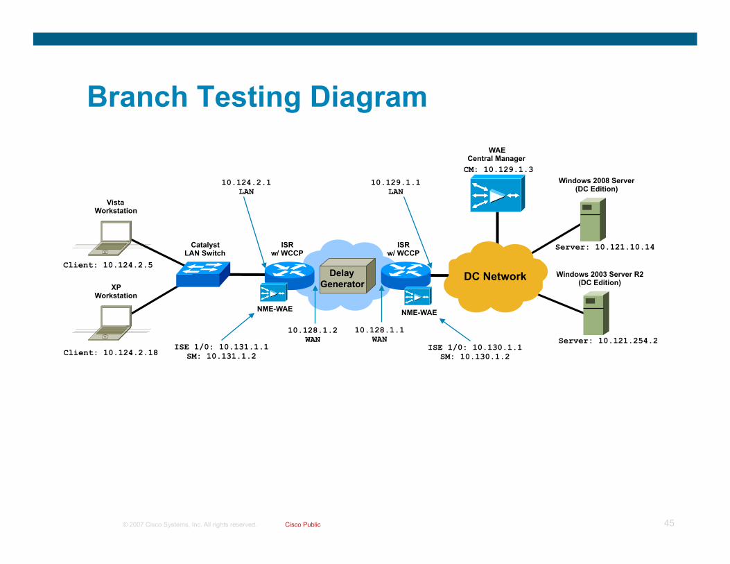
Branch Testing Diagram WAE
Central Manager
NME-WAE
ISR w/ WCCP
Catalyst LAN Switch
Vista Workstation
Windows 2008 Server (DC Edition)
ISR w/ WCCP
10.124.2.1 LAN
10.128.1.2 WAN
ISE 1/0: 10.131.1.1 SM: 10.131.1.2
Client: 10.124.2.5
Server: 10.121.10.14
10.129.1.1 LAN
CM: 10.129.1.3
10.128.1.1 WAN
DC Network XP
Workstation
Client: 10.124.2.18
Windows 2003 Server R2 (DC Edition)
Server: 10.121.254.2
NME-WAE
ISE 1/0: 10.130.1.1 SM: 10.130.1.2
Delay Generator
© 2007 Cisco Systems, Inc. All rights reserved. Cisco Public 46
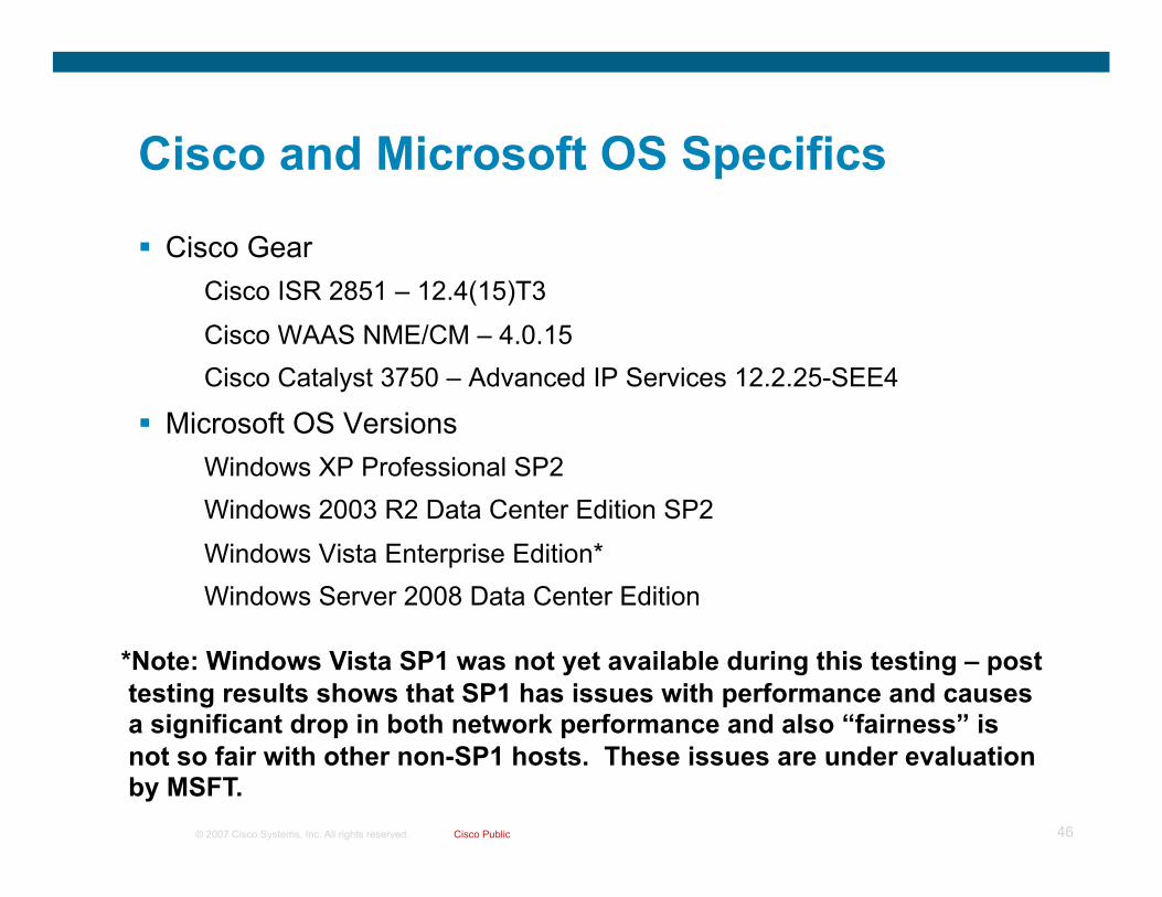
Cisco and Microsoft OS Specifics
Cisco Gear Cisco ISR 2851 – 12.4(15)T3
Cisco WAAS NME/CM – 4.0.15 Cisco Catalyst 3750 – Advanced IP Services 12.2.25-SEE4
Microsoft OS Versions Windows XP Professional SP2 Windows 2003 R2 Data Center Edition SP2
Windows Vista Enterprise Edition* Windows Server 2008 Data Center Edition
*Note: Windows Vista SP1 was not yet available during this testing – post testing results shows that SP1 has issues with performance and causes a significant drop in both network performance and also “fairness” is not so fair with other non-SP1 hosts. These issues are under evaluation by MSFT.

© 2007 Cisco Systems, Inc. All rights reserved. Cisco Public 47
Validation Tools – Overview
SMB, HTTP (IIS 6.0 and 7.0) and FTP (6.0) were used Tools that are native to OS were used (browser, command-line tools) All Operating Systems and applications were using default settings
(except when comparing TCP features such as CTCP) Sniffer was running during validation baseline test (with/without WAAS) to
capture end-to-end behavior (sniffer did not run during performance cases)
Output from all tests were captured to logs Windows performance monitoring tools were running during baseline
testing to ensure consistency with BW reported from command-line tools Client and Server OS versions were tested in all combinations (Vista/
2008, Vista/2003, XP/2008 and XP/2003) and traffic was transmitted from the client (TX) and to the client (RX)
Routers/Switches run for connectivity only – meaning no QoS, MTU changes, ACLs, etc…

© 2007 Cisco Systems, Inc. All rights reserved. Cisco Public 48
Validation Tools and Methodology (1) Client/Server Tools - SMB
XCOPY and ROBOCOPY
Scripts were created to map drives, TX/RX files, capture times/throughput
Report results into Microsoft Excel spreadsheet
Test iterations were delayed between runs
Does not report msec
C:\>robocopy z:\waas-download c:\ iso-file-131m.iso /IS
-----------------------------------------------------------------------
ROBOCOPY :: Robust File Copy for Windows
-----------------------------------------------------------------------
Started : Wed Apr 16 12:52:34 2008
Source : z:\waas-download\
Dest : c:\
Files : iso-file-131m.iso
Options : /COPY:DAT /IS /R:1000000 /W:30
-----------------------------------------------------------------------
1 z:\waas-download\
100% Same 131.3 m iso-file-131m.iso
-----------------------------------------------------------------------
Total Copied Skipped Mismatch FAILED Extras
Dirs : 1 0 1 0 0 0
Files : 1 1 0 0 0 0
Bytes : 131.33 m 131.33 m 0 0 0 0
Times : 0:06:23 0:06:23 0:00:00 0:00:00
Speed : 359206 Bytes/sec.
Speed : 20.553 MegaBytes/min.
Ended : Wed Apr 16 12:58:58 2008

© 2007 Cisco Systems, Inc. All rights reserved. Cisco Public 49
HTTP transfers – Baseline used both IE browser and wget.exe
wget.exe was used for bulk of testing as it was easy to script, allows for no client caching (good for automation) and reports both time to transfer and throughput accurately. Time was calculated from test start/end time.
Results were reported into Microsoft Excel spreadsheet
Validation Tools and Methodology (2) Client/Server Tools - HTTP
C:\>wget --no-cache http://10.121.10.14/waas-download/doc-file-2.41m.doc
--13:36:32-- http://10.121.10.14/waas-download/doc-file-2.41m.doc
=> `doc-file-2.41m.doc.6'
Connecting to 10.121.10.14:80... connected.
HTTP request sent, awaiting response... 200 OK
Length: 2,529,792 (2.4M) [application/msword]
100%[====================================>] 2,529,792 10.52M/s
13:36:32 (10.52 MB/s) - `doc-file-2.41m.doc.6' saved [2529792/2529792]

© 2007 Cisco Systems, Inc. All rights reserved. Cisco Public 50
FTP transfers – Baseline used both IE browser and ftp.exe
ftp.exe was used for bulk of testing as it was easy to script, allows for no caching (good for automation) and reports both time to transfer and throughput accurately. Results were reported into Microsoft Excel spreadsheet
Validation Tools and Methodology (3) Client/Server Tools - FTP
C:\>ftp -A -s:ftp-rx-config.txt 10.121.10.14
Connected to 10.121.10.14.
220 Microsoft FTP Service
...
ftp> get doc-file-2.41m.doc
200 PORT command successful.
150 Opening BINARY mode data connection for doc-file-2.41m.doc(2529792 bytes).
226 Transfer complete.
ftp: 2529792 bytes received in 0.25Seconds 10119.17Kbytes/sec.
ftp>
© 2007 Cisco Systems, Inc. All rights reserved. Cisco Public 51
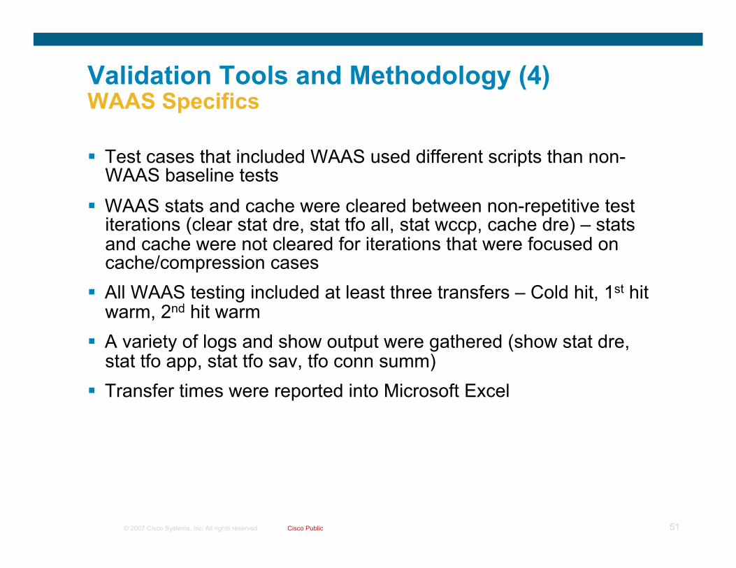
Validation Tools and Methodology (4) WAAS Specifics
Test cases that included WAAS used different scripts than non-WAAS baseline tests
WAAS stats and cache were cleared between non-repetitive test iterations (clear stat dre, stat tfo all, stat wccp, cache dre) – stats and cache were not cleared for iterations that were focused on cache/compression cases
All WAAS testing included at least three transfers – Cold hit, 1st hit warm, 2nd hit warm
A variety of logs and show output were gathered (show stat dre, stat tfo app, stat tfo sav, tfo conn summ)
Transfer times were reported into Microsoft Excel

© 2007 Cisco Systems, Inc. All rights reserved. Cisco Public 52
Branch Test Cases
1.544 Mbps @ 50, 80, 150ms
3.0 Mbps @ 50, 150ms
Delay generator was used between sites to induce delay – each test case was subject to fixed and variable loss percentages from zero loss to as high as 5% to compare TCP/IP stack performance

© 2007 Cisco Systems, Inc. All rights reserved. Cisco Public 53
Branch Testing Results - Summary

© 2007 Cisco Systems, Inc. All rights reserved. Cisco Public 54
Microsoft TCP/IP Performance Summary
Windows Vista provides a massive improvement over Windows XP in transfer times and throughput in certain situations such as environments where there is high-bandwidth and high-delay
In addition to TCP/IP improvements, additional gains are realized with the many improvements found in SMB 2.0
The customer needs to carefully evaluate Windows Vista in the branch environment to ensure interoperability of the new TCP/IP features and network components such as Firewalls, Load-balancer and legacy devices
TCP Auto-tuning, CTCP, ECN and RFC1323 can cause performance issues and even loss of connectivity in certain situations where the network device does not yet support large window size negotiation, the presence of ECN bits and other high-speed TCP functions

© 2007 Cisco Systems, Inc. All rights reserved. Cisco Public 55
SMB Throughput Test Variable BW, Delay
Dramatic improvement in throughput via TCP optimization and also SMB 2.0 enhancement

© 2007 Cisco Systems, Inc. All rights reserved. Cisco Public 56
SMB Time to Transfer Variable BW, Delay

© 2007 Cisco Systems, Inc. All rights reserved. Cisco Public 57
SMB Time to Transfer Loss Comparison (Zero vs. Variable)
Windows Vista is improved over XP not only as delay increases but also when loss is present

© 2007 Cisco Systems, Inc. All rights reserved. Cisco Public 58
SMB Throughput Loss Comparison (Zero vs. Variable)

© 2007 Cisco Systems, Inc. All rights reserved. Cisco Public 59
SMB Time to Transfer TCP Feature Comparison
Not all TCP optimization features show improvement in all cases – Here Vista with CTCP enabled (not the default) does not show any measurable improvement (conditions in this test were not suitable for CTCP gains)

© 2007 Cisco Systems, Inc. All rights reserved. Cisco Public 60
HTTP Throughput Variable BW, Delay
Remember that the application can (and does) impact performance. For example the registry can be modified to override the default data buffer size used by HTTP.sys – Here we see that performance is similar at all BW rates but auto-tuning does help in high delay environments

© 2007 Cisco Systems, Inc. All rights reserved. Cisco Public 61
HTTP Throughput Variable BW, Delay and Loss
Same test as before only with loss added to the network – It is obvious to see how Vista/2003 can recover from loss compared to XP/2003
© 2007 Cisco Systems, Inc. All rights reserved. Cisco Public 62
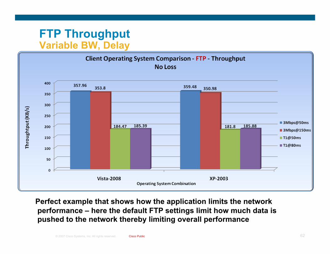
FTP Throughput Variable BW, Delay
Perfect example that shows how the application limits the network performance – here the default FTP settings limit how much data is pushed to the network thereby limiting overall performance

© 2007 Cisco Systems, Inc. All rights reserved. Cisco Public 63
Microsoft Windows Vista + Cisco WAAS
Even with the great TCP performance improvements that come with Windows Vista and Windows Server 2008 there are distinct advantages to using WAAS in the network
Windows Vista does NOT provide compression or caching – the following slides are a few of the many examples where both compression and caching prove to be very valuable in application performance
TCP Optimization
Caching Compression
Microsoft Windows Vista/ Server 2008
Auto-tuning, CTCP, RFC1323
No No
Cisco WAAS Yes (TFO) Yes (DRE) Yes (LZ)
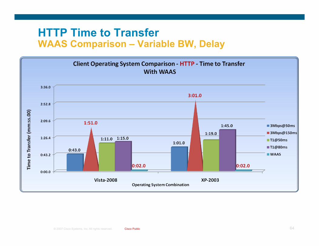
© 2007 Cisco Systems, Inc. All rights reserved. Cisco Public 64
HTTP Time to Transfer WAAS Comparison – Variable BW, Delay

© 2007 Cisco Systems, Inc. All rights reserved. Cisco Public 65
FTP Time to Transfer WAAS Comparison – Variable BW, Delay

© 2007 Cisco Systems, Inc. All rights reserved. Cisco Public 66
Branch Performance Impact Summary
Windows Vista alone or in combination with Server 2008 offer impressive network performance improvements when the conditions are right
Time will tell if the constant “tuning” of every single TCP flow over a network connection that rarely changes (BW, Delay or Loss) ends up causing issues
Some features of the new stack may cause issues with legacy or non-RFC compliant networking gear
There is no substitute for the performance improvements offered by WAAS when TFO/DRE/LZ are used

© 2007 Cisco Systems, Inc. All rights reserved. Cisco Public 67
Data Center Impact

© 2007 Cisco Systems, Inc. All rights reserved. Cisco Public 68
Purpose of Testing Windows Vista and Server 2008 in the Data Center
Determine impact of new TCP/IP stack and Clustering on DC-related services and designs such as:
Interoperability with ACE Impact on Data Center bandwidth requirements within and between DC sites Design changes when using WSFC (Windows Server Failover Cluster) in a Layer 3 configuration (Local and GeoCluster)
Yield updated best practice recommendations, if needed, for the field and customers to use when deploying Windows Vista and Server 2008
Provide Microsoft and Cisco product teams information about performance and, if found, issues related to Windows Vista TCP/IP stack
© 2007 Cisco Systems, Inc. All rights reserved. Cisco Public 69
Validation Setup & Methodology – TCP Stack Performance

© 2007 Cisco Systems, Inc. All rights reserved. Cisco Public 70
Data Center TCP Stack Test Diagram
Delay Generator
Secondary Data Center
Windows Server 2003 w2k3-svr-3: 10.6.100.3
Windows Server 2008 w2k8-svr-3: 10.6.100.4
VLAN 100
Primary Data Center
Windows Server 2003 w2k3-svr-1: 10.121.12.30
Windows Server 2008 w2k8-svr-1: 10.121.12.20
VLAN 12
Windows Server 2003 w2k3-svr-2: 10.121.12.35
Windows Server 2008 w2k8-svr-2: 10.121.12.25

© 2007 Cisco Systems, Inc. All rights reserved. Cisco Public 71
Cisco and Microsoft OS Specifics
Cisco Gear Cisco Catalyst 6509 with Supervisor 720 – Advanced Ent Services 12.2.18-SXF13
Microsoft OS Versions Windows 2003 R2 Data Center Edition SP2
Windows Server 2008 Data Center Edition
© 2007 Cisco Systems, Inc. All rights reserved. Cisco Public 72
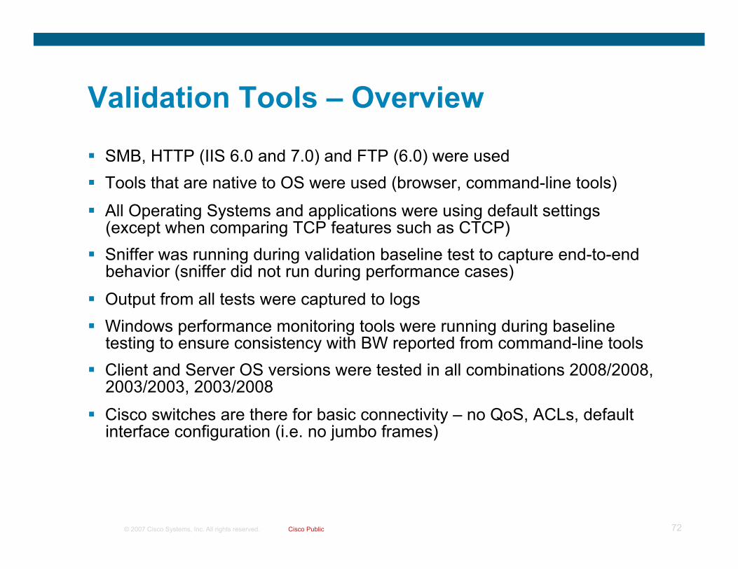
Validation Tools – Overview
SMB, HTTP (IIS 6.0 and 7.0) and FTP (6.0) were used Tools that are native to OS were used (browser, command-line tools)
All Operating Systems and applications were using default settings (except when comparing TCP features such as CTCP)
Sniffer was running during validation baseline test to capture end-to-end behavior (sniffer did not run during performance cases)
Output from all tests were captured to logs Windows performance monitoring tools were running during baseline
testing to ensure consistency with BW reported from command-line tools Client and Server OS versions were tested in all combinations 2008/2008,
2003/2003, 2003/2008 Cisco switches are there for basic connectivity – no QoS, ACLs, default
interface configuration (i.e. no jumbo frames)

© 2007 Cisco Systems, Inc. All rights reserved. Cisco Public 73
Data Center Test Cases
10, 100, Mbps @ <1ms, 5ms, 50ms, 150ms 1000 Mbps @ <1ms, 5ms, 50ms Delay generator was used between sites to induce
delay – each test case was subject to fixed and variable loss percentages from zero loss to as high as 5% to compare TCP/IP stack performance
Summary of results (following slides) had variable loss injected unless noted with “Zero Loss” (used as a baseline)

© 2007 Cisco Systems, Inc. All rights reserved. Cisco Public 74
Windows Server 2008 TCP Optimization TCP Feature Comparison – SMB 2.0
Baseline – W2K8 defaults (Auto-tuning=Normal, CTCP=enabled) No CTCP test only impacts transmit No Auto-tuning – Basically reduces W2K8 to W2K3 performance

© 2007 Cisco Systems, Inc. All rights reserved. Cisco Public 75
HTTP Throughput Local DC Comparison – Zero Loss
© 2007 Cisco Systems, Inc. All rights reserved. Cisco Public 76
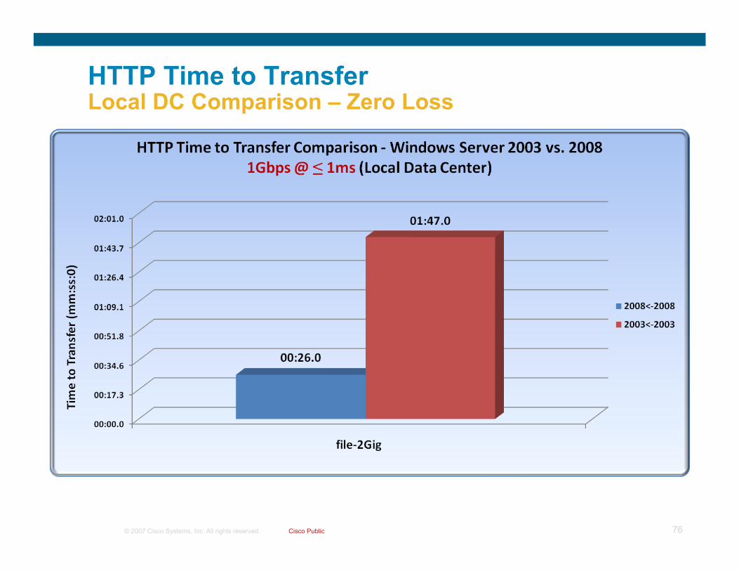
HTTP Time to Transfer Local DC Comparison – Zero Loss

© 2007 Cisco Systems, Inc. All rights reserved. Cisco Public 77
SMB Time to Transfer Local DC Comparison – Zero Loss

© 2007 Cisco Systems, Inc. All rights reserved. Cisco Public 78
FTP Time to Transfer Local DC Comparison – Zero Loss

© 2007 Cisco Systems, Inc. All rights reserved. Cisco Public 79
FTP Throughput Local DC Comparison – Zero Loss

© 2007 Cisco Systems, Inc. All rights reserved. Cisco Public 80
HTTP Throughput Varying Link Speeds
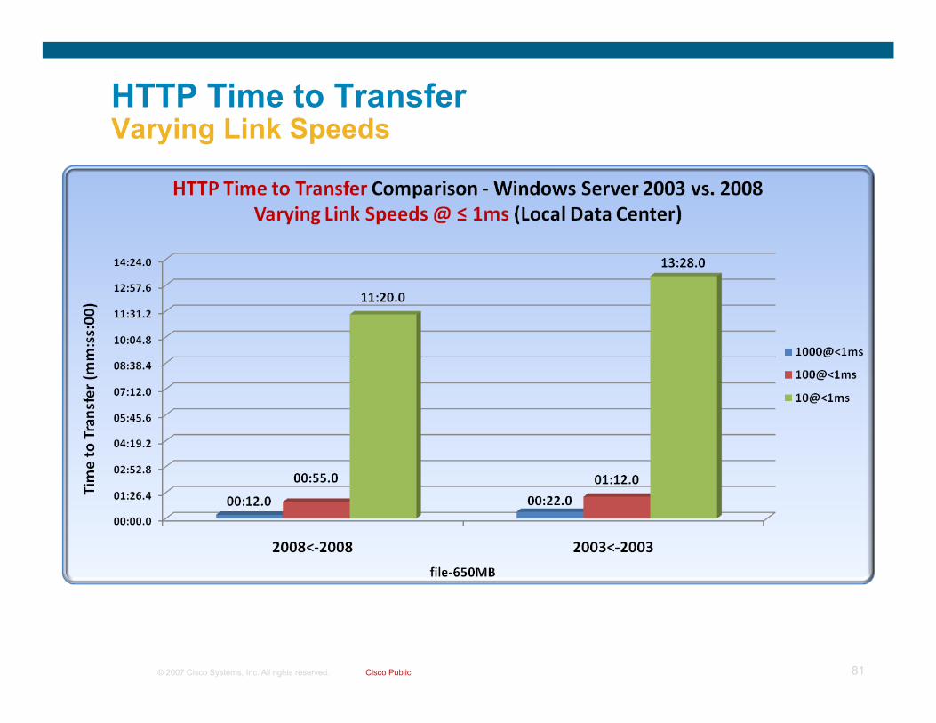
© 2007 Cisco Systems, Inc. All rights reserved. Cisco Public 81
HTTP Time to Transfer Varying Link Speeds

© 2007 Cisco Systems, Inc. All rights reserved. Cisco Public 82
SMB Time to Transfer Varying Link Speeds

© 2007 Cisco Systems, Inc. All rights reserved. Cisco Public 83
FTP Throughput Varying Link Speeds

© 2007 Cisco Systems, Inc. All rights reserved. Cisco Public 84
FTP Time to Transfer Varying Link Speeds

© 2007 Cisco Systems, Inc. All rights reserved. Cisco Public 85
HTTP Throughput Varying Link Speeds @ 50ms Delay

© 2007 Cisco Systems, Inc. All rights reserved. Cisco Public 86
HTTP Time to Transfer Varying Link Speeds @ 50ms Delay

© 2007 Cisco Systems, Inc. All rights reserved. Cisco Public 87
SMB Time to Transfer Varying Link Speeds @ 50ms Delay

© 2007 Cisco Systems, Inc. All rights reserved. Cisco Public 88
FTP Throughput Varying Link Speeds @ 50ms Delay

© 2007 Cisco Systems, Inc. All rights reserved. Cisco Public 89
FTP Time to Transfer Varying Link Speeds @ 50ms Delay
© 2007 Cisco Systems, Inc. All rights reserved. Cisco Public 90
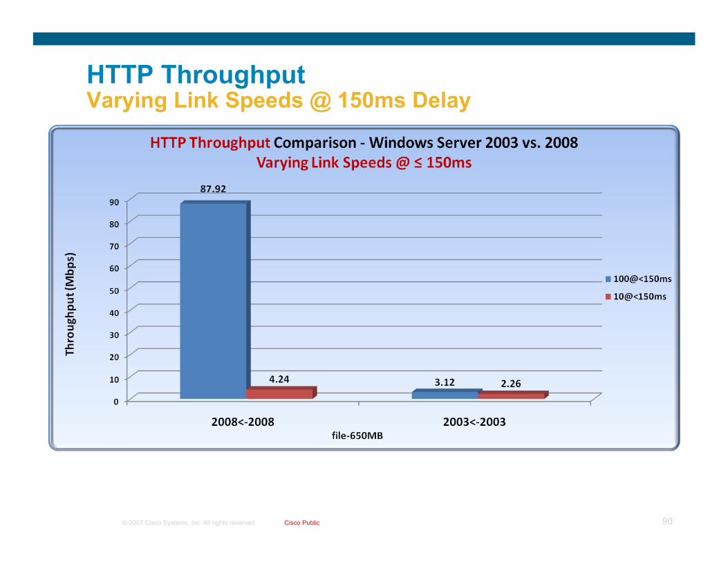
HTTP Throughput Varying Link Speeds @ 150ms Delay

© 2007 Cisco Systems, Inc. All rights reserved. Cisco Public 91
HTTP Time to Transfer Varying Link Speeds @ 150ms Delay

© 2007 Cisco Systems, Inc. All rights reserved. Cisco Public 92
SMB Time to Transfer Varying Link Speeds @ 150ms Delay

© 2007 Cisco Systems, Inc. All rights reserved. Cisco Public 93
FTP Throughput Varying Link Speeds @ 150ms Delay

© 2007 Cisco Systems, Inc. All rights reserved. Cisco Public 94
FTP Time to Transfer Varying Link Speeds @ 150ms Delay

© 2007 Cisco Systems, Inc. All rights reserved. Cisco Public 95
DC TCP Performance Impact Summary
Windows Server 2008 with TCP and SMB 2.0 provides a massive performance improvement over Server 2003 within the DC and between DC locations
Will the increase in throughput impact existing design recommendations? (related to oversubscription ratios, QoS settings or performance strain)
Again, time will tell if the constant auto-tuning of each flow makes good sense in the DC vs. nailing the window to a specific value for a purpose-driven server (like we do with Server 2003 and Linux server today)
© 2007 Cisco Systems, Inc. All rights reserved. Cisco Public 96
TCP Interoperability with Cisco ACE

© 2007 Cisco Systems, Inc. All rights reserved. Cisco Public 97
Microsoft Windows Vista/2008 and Cisco ACE TCP Interoperability Summary
By default the Cisco ACE TCP normalization feature prohibits Vista/2008 ‘advanced’ TCP features (auto-tuning, RFC1323 Timestamps, SACKs, etc…)
Configure parameter maps to allow options or clear them and set your own values Enabling the “buffer sharing” option on ACE can maximize TCP receive buffer operation between hosts and ACE – This should be extensively tested by customer before deploying in their environment
Application probes to Server 2008 will fail if Windows Firewall is not configured to allow the probes
Cat6k
ACE

© 2007 Cisco Systems, Inc. All rights reserved. Cisco Public 98
Validation Setup & Methodology – TCP Stack Interoperability

© 2007 Cisco Systems, Inc. All rights reserved. Cisco Public 99
Windows Vista/2008 + ACE Validation Diagram
ACE
Windows Server 2008
VLAN114
Windows Vista Clients
MSFC
6500 Chassis
Campus VLAN14
10.120.2.95 - 99 VIP 10.121.14.11
Real: 10.121.14.16- 20

© 2007 Cisco Systems, Inc. All rights reserved. Cisco Public 100
Cisco and Microsoft OS Specifics
Cisco Gear Cisco Catalyst 6509 with Supervisor 720 – Advanced Ent Services 12.2.18-SXF13 Cisco ACE Service Module - Version A2(1.0a) [build 3.0(0)A2(1.0a) Cisco NAM (WS-SVC-NAM-2) - 3.6(1a-Patch3)
Microsoft OS Versions Windows Vista Enterprise Edition Windows Server 2008 Data Center Edition

© 2007 Cisco Systems, Inc. All rights reserved. Cisco Public 101
Validation Tools – Overview
HTTP (IE7 and wget) on client – IIS7 on Server IE7/Firefox uses a windows scaling factor of 2 by default
wget uses the OS default of windows scaling factor of 8
All Operating Systems and applications were using default settings (except when comparing TCP features such as RFC 1323 Timestamps)
Cisco NAM was running during validation baseline test to capture end-to-end behavior
Output from all tests were captured to logs
Cisco switches are there for basic connectivity – no QoS, ACLs, default interface configuration (i.e. no jumbo frames)

© 2007 Cisco Systems, Inc. All rights reserved. Cisco Public 102
Data Center Test Cases
Validation for interoperability and ACE operation impact was based on the following test cases:
Baseline with no VIP - Determine impact of normalization, no normalization and parameter-map to allow TCP options (SACK, Timestamps, Windows Scaling)
VIP with L4 Policy – Same validation as with baseline
VIP with L7 Policy – Baseline + various buffer-share and windows scaling settings – parameter maps were enabled in different combinations towards client and/or towards server
Note: Performance was not tested. Sniffer captures were taken on both sides of the ACE and on the ACE to ensure that the settings matched or could be altered correctly by the ACE and that the application functioned properly.

© 2007 Cisco Systems, Inc. All rights reserved. Cisco Public 103
Cisco ACE TCP Normalization
10.120.2.99 10.121.14.16 TCP 54428 > http [SYN] Seq=0 Win=8192 Len=0 MSS=1460 WS=2
Window scale: 2 (multiply by 4)
10.121.14.16 10.120.2.99 TCP http > 54428 [SYN, ACK] Seq=0 Ack=1 Win=8192 Len=0 MSS=1460
10.120.2.99 10.121.14.16 TCP 54564 > http [SYN] Seq=0 Win=8192 Len=0 MSS=1460 WS=2
10.121.14.16 10.120.2.99 TCP http > 54564 [SYN, ACK] Seq=0 Ack=1 Win=8192 Len=0 MSS=1460 WS=8
Window scale: 8 (multiply by 256)
TCP Normalization is on by default – will clear TCP options (windows scale, timestamps, SACK, etc..)
SYN, ACK has no options set as the options never reached the server because TCP normalization cleared them (WS is missing)
Disabling normalization OR using a parameter map can allow options to be “allowed” through the ACE
interface vlan 114 description North Side ACE VLAN bridge-group 1 no normalization
parameter-map type connection TCP_PARAM_MAP tcp-options selective-ack allow tcp-options window-scale allow
Client Server

© 2007 Cisco Systems, Inc. All rights reserved. Cisco Public 104
Cisco ACE – RFC 1323 Timestamps
TCP 54190 > http [SYN] Seq=0 Win=8192 Len=0 MSS=1460 WS=2 TSV=6517994 TSER=0
Options: (20 bytes) Maximum segment size: 1460 bytes NOP Window scale: 2 (multiply by 4) SACK permitted Timestamps: TSval 6517994, TSecr 0
TCP http > 54190 [SYN, ACK] Seq=0 Ack=1 Win=8192 Len=0 MSS=1460 WS=8 TSV=6716945 TSER=6517994
Options: (20 bytes) Maximum segment size: 1460 bytes NOP Window scale: 8 (multiply by 256) SACK permitted Timestamps: TSval 6716945, TSecr 6517994
C:\>netsh int tcp sh gl
TCP Global Parameters
----------------------------------------------
Receive-Side Scaling State : enabled
Chimney Offload State : enabled
Receive Window Auto-Tuning Level : normal
Add-On Congestion Control Provider : none
ECN Capability : disabled
RFC 1323 Timestamps : enabled
parameter-map type connection TCP_PARAM_MAP tcp-options selective-ack allow tcp-options timestamp allow tcp-options window-scale allow
Note: Timestamps are disabled by default on Vista/2008

© 2007 Cisco Systems, Inc. All rights reserved. Cisco Public 105
Modifying Buffer Sharing – Client Facing Should you do this? Probably not
Cisco ACE supports increasing the TCP window RX buffer space – modifying this value will impact the advertised window size from the ACE in certain situations (see results table)
Cisco ACE has a default buffer-space of 32768 and can be configured up to a max of 262143
Just because you have the capability to increase the buffer share value on the client side does not mean you should
Only in rare cases would this be a good idea (increasing buffer share on the server side would be more appropriate)
Negative performance if buffer-share + windows scaling is used on ACE and the ACE is receiving large volumes of connections and data transfers - Remember that the buffer share is per connection and with any vendor, a shared resource with a high number of connections on that resource will exhaust the buffer if the value is set too high
parameter-map type connection TCP_OPTIONS_MAP set tcp buffer-share 262143

© 2007 Cisco Systems, Inc. All rights reserved. Cisco Public 106
Buffer Sharing + Window Scaling Advertised To Client
Example with Windows Vista client and ACE with default buffer-share of 32768 (ACE sends window size of 128) X default WS=0 (multiplier=1)
Extreme example with ACE with max buffer-share of 262143 (ACE sends window size of 255) X max WS=14 (multiplier 16,384) = 4177920
10.121.14.11 10.120.2.99 TCP http > 62611 [SYN, ACK] Seq=0 Ack=1 Win=128 Len=0 MSS=1460…WS=0
10.121.14.11 10.120.2.99 TCP http > 59864 [SYN, ACK] Seq=0 Ack=1 Win=255 Len=0 MSS=1460…WS=14
Window scale: 14 (multiply by 16384)
15837 … 66560 10.120.2.99 10.121.14.11 TCP 59864 > http [ACK] Seq=1 Ack=1 Win=66560 Len=0 15838 … 66560 10.120.2.99 10.121.14.11 HTTP GET /3mfile.msi HTTP/1.0 15839 … 4177920 10.121.14.11 10.120.2.99 TCP http > 59864 [ACK] Seq=1 Ack=129 Win=4177920 Len=0

© 2007 Cisco Systems, Inc. All rights reserved. Cisco Public 107
Modifying Buffer Sharing – Server Facing This may be a good idea in some cases
Modifying the buffer-share for connections from server can help with high BDP situations such as a WAN (see Cisco Application Networking for SAP Design Guide http://www.cisco.com/go/srnd)
By default, on L7 client-initiated connections, the server receives a modified advertised window size in the SYN from the ACE which is the buffer-share default of 32,768
10.120.2.99 10.121.14.16 TCP 62611 > http [SYN] Seq=0 Win=32768 Len=0 MSS=1460 WS=8
10.120.2.99 10.121.14.11 TCP 62611 > http [SYN] Seq=0 Win=8192 Len=0 MSS=1460 WS=8
Traf
fic F
low
VIP=10.121.14.11
Rewrite src->10.120.2.99,dst->10.121.14.16,Win=32768 (buffer-share)
Windows Vista Client (establishing HTTP connection for file download)
Windows Server 2008

© 2007 Cisco Systems, Inc. All rights reserved. Cisco Public 108
ACE Buffer-Share and Window Scale Impact on Advertised Window Size/WS – Client RX
ACE Default buffer-share size: 32768 ACE Default Window Scale (WS): 0
ACE max buffer-share size: 262143 ACE max Window Scale (WS): 14

© 2007 Cisco Systems, Inc. All rights reserved. Cisco Public 109
Vista Client TX file via HTTP
ACE-Advertised Window Size to Client
ACE-Advertised WS Value to Client
ACE-Advertised Window Size to Server
ACE-Advertised WS Value to Server
Note:
Client Policy Buffer-share/WS = Default
8192 8 8192 8 Client/SVR SYN=8192/WS=8
Client Policy Buffer-Share=Max
8192 – Vista Changes to 65535 Window Size
8 8192 8 No large windows
Client Policy Buffer-Share/WS=Max
8192 – Vista Changes to 65535 Window Size
8 8192 8 ACE sends 4MB window (4177920)
Server Policy Buffer-Share/WS=Default
8192 8 8192 8 SVR sends window =8192/WS8 (2097152=256*8192)
Server Policy Buffer-Share=Max
8192 8 8192 8 SVR sends window of (2097152)
Server Policy Buffer-Share/WS=Max
8192 8 8192 8 SVR sends window of (2097152)
ACE Buffer-Share and Window Scale Impact on Advertised Window Size/WS – Client TX

© 2007 Cisco Systems, Inc. All rights reserved. Cisco Public 110
Health Probes – Window Server 2008 HTTP Probe
In Windows Server 2008 the Windows Firewall is enabled by default
Usually, at the time of installation of server “roles” or “features” certain Windows Firewall rules will be modified to allow inbound traffic – additionally rules may need to be created/modified depending on your needs
For example, if the “Web Server (IIS)” role has been installed the system will modify the Windows Firewall rules for
Windows Firewall Exception

© 2007 Cisco Systems, Inc. All rights reserved. Cisco Public 111
Health Probes – Window Server 2008 ICMP Probe
By default Windows Firewall drops all traffic inbound to the server unless it first originates from the server or has been allowed via a rule – this includes ICMP
If ICMP probes are used on the ACE, the Windows Firewall must either be disabled for the appropriate Network Profile (Domain, Private, Public) or the “ICMPv4-In” rule needs to be enabled to allow connections – optionally the ACE mgmt address for context can be permitted
--------------------- probe results -------------------- probe association probed-address probes failed passed health ------------------- ---------------+----------+----------+----------+------- serverfarm : WEB real : w2k8-web-01[0] 10.121.14.16 300 300 0 FAILED

© 2007 Cisco Systems, Inc. All rights reserved. Cisco Public 112
Windows Server Failover Clusters @ Layer 3

© 2007 Cisco Systems, Inc. All rights reserved. Cisco Public 113
Windows Server 2008 – Windows Server Failover Cluster (WSFC)
Dramatically improves deployment and management of clusters
Keeps existing support for Layer 2 based clusters
Adds support for what Microsoft calls “Multisite” clusters (AKA: Layer 3 or GeoClusters)
Offers the customer a way to have cluster nodes in different parts of the DC or across DC locations without stretching/extending VLANs
Purpose of Cisco validation of the WSFC Multisite option is to ensure:
Interoperability in the Data Center
Offer support/improvements on the Layer 3 aspects of the cluster design

© 2007 Cisco Systems, Inc. All rights reserved. Cisco Public 114
Network Challenges with Layer 2 Failover Clusters L2 adjacency requirement restricts the proximity of nodes to the same aggregation
switch pair unless there is support for extending VLANs beyond a single aggregation pair
L2 adjacency also requires that VLANs be extended to other DC locations for the network and SAN connections if nodes are deployed in multiple locations
Data Center
Extend VLANs Across Metro/WAN Extend VLANs
Across Aggregation
Data Center
© 2007 Cisco Systems, Inc. All rights reserved. Cisco Public 115
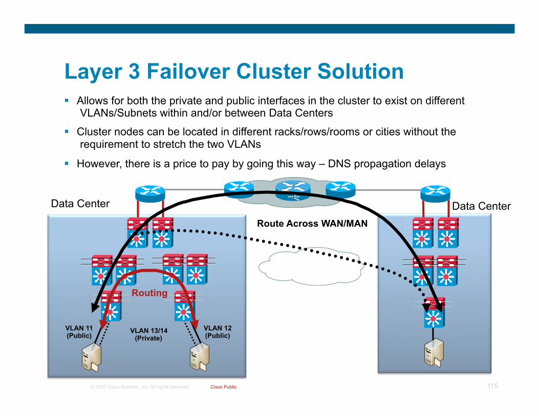
Layer 3 Failover Cluster Solution Allows for both the private and public interfaces in the cluster to exist on different
VLANs/Subnets within and/or between Data Centers
Cluster nodes can be located in different racks/rows/rooms or cities without the requirement to stretch the two VLANs
However, there is a price to pay by going this way – DNS propagation delays
Data Center Route Across WAN/MAN
Data Center
VLAN 11 (Public)
VLAN 12 (Public)
VLAN 13/14 (Private)
Routing

© 2007 Cisco Systems, Inc. All rights reserved. Cisco Public 116
Challenges with L3/Multisite Clusters
All based on DNS updates for the change in address Relies on DNS registration so that records can be updated
automatically (non-DNS registration still works but requires that the record be changed manually)
HostRecordTTL value for the cluster resource in DNS is 20 minutes by default – this is the maximum time before the client expires the TTL for the record
Microsoft has a recommendation of 5 minutes (based on recommendations for Exchange Server)
But, we have additional solutions other than depending on DNS

© 2007 Cisco Systems, Inc. All rights reserved. Cisco Public 117
Multisite Clusters – Recovery Options Option 1:Default Behavior – 20 minute DNS setting
Client has mapped drive to file share on cluster
Node 1 fails Node 2 becomes active for cluster
resource DNS is updated with the new IP
address resource The client DNS cache entry waits
until the TTL expires (default is 20 minutes) before reconnecting to the share on Node 2
Client in Campus/Branch/Remote
Local DC
Windows Server 2008 Node1 w2k8-cls-01: 10.121.11.50
Windows Server 2008 Node 2 w2k8-cls-02: 10.121.12.50
VLAN 11 (Public)
VLAN 12 (Public)
Agg Layer
VLAN 13/14 (Private)
Access Layer
Mapped drive to File Share: \\clustered-fs\share
DNS Server
File Server Cluster: 10.121.11.52 Owner: Node 1
Clustered-FS Host(A) 10.121.12.52
C:\>ipconfig /displaydns
clustered-fs
----------------------------------------
Record Name . . . . . : clustered-fs.cisco.com
Time To Live . . . . : 1196
A (Host) Record . . . : 10.121.11.52
File Server Cluster: 10.121.12.52 Owner: Node 2
C:\>ipconfig /displaydns
clustered-fs
----------------------------------------
Record Name . . . . . : clustered-fs.cisco.com
Time To Live . . . . : 1198
A (Host) Record . . . : 10.121.12.52
Client DNS Cache expires for old entry (Default=20 minutes)
Clustered-FS Host(A) 10.121.11.52 #Default HostRecordTTL = 1200 Seconds
Note: not a valid solution in static DNS environments
© 2007 Cisco Systems, Inc. All rights reserved. Cisco Public 118
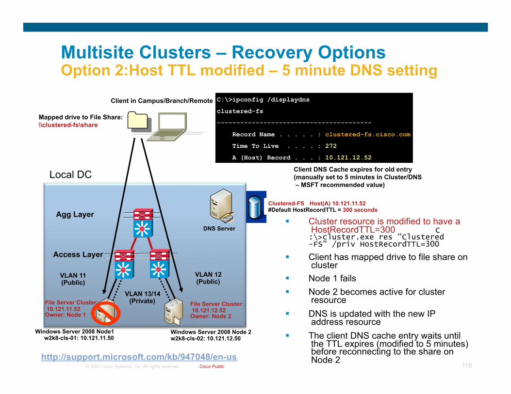
Multisite Clusters – Recovery Options Option 2:Host TTL modified – 5 minute DNS setting
Cluster resource is modified to have a HostRecordTTL=300 C:\>cluster.exe res "Clustered-FS" /priv HostRecordTTL=300
Client has mapped drive to file share on cluster
Node 1 fails Node 2 becomes active for cluster
resource DNS is updated with the new IP
address resource The client DNS cache entry waits until
the TTL expires (modified to 5 minutes) before reconnecting to the share on Node 2
Client in Campus/Branch/Remote
Local DC
Windows Server 2008 Node1 w2k8-cls-01: 10.121.11.50
Windows Server 2008 Node 2 w2k8-cls-02: 10.121.12.50
VLAN 11 (Public)
VLAN 12 (Public)
Agg Layer
VLAN 13/14 (Private)
Access Layer
Mapped drive to File Share: \\clustered-fs\share
DNS Server
File Server Cluster: 10.121.11.52 Owner: Node 1
Clustered-FS Host(A) 10.121.12.52
C:\>ipconfig /displaydns
clustered-fs
----------------------------------------
Record Name . . . . . : clustered-fs.cisco.com
Time To Live . . . . : 291
A (Host) Record . . . : 10.121.11.52
File Server Cluster: 10.121.12.52 Owner: Node 2
C:\>ipconfig /displaydns
clustered-fs
----------------------------------------
Record Name . . . . . : clustered-fs.cisco.com
Time To Live . . . . : 272
A (Host) Record . . . : 10.121.12.52
Client DNS Cache expires for old entry (manually set to 5 minutes in Cluster/DNS – MSFT recommended value)
Clustered-FS Host(A) 10.121.11.52 #Default HostRecordTTL = 300 seconds
http://support.microsoft.com/kb/947048/en-us

© 2007 Cisco Systems, Inc. All rights reserved. Cisco Public 119
Network-based Options Mask the cluster IP address resource change from the client – NAT works great for
this! Several options for doing this:
Do NAT at the Aggregation switch in front of the server farm Allow for complete automation by using the Cisco ACE to monitor the cluster nodes and
application availability and perform failover/recovery on behalf of the client Do NAT on whatever you like but it must be able to perform well since there may be many
clients/sessions connecting to the cluster resource
Automation options Network devices can be updated manually upon cluster IP address resource change
(slowest recovery method and the one most prone to error – Good in a Multisite DC where the admin controls when/where the cluster recovery happens)
Basic script can be used to monitor the cluster resources/notifications (could even use RHI) and when the standby cluster node becomes active for the resource the script can activate the change on the network device (Similar to manual method above only automated – in a Multisite DC failure event the device running the script may not have access to the now active DC devices)
Poll the Microsoft Cluster for events using the Cluster API and run a script to make changes to the network device (Fully automated but slower failover event as this ‘pull’ model will work on a timer and the failure may occur between polling events)
Use a custom resource DLL and make the resource dependent on the Network Name and upon failure the Cisco resource DLL would come online and determine what to change on the network (Optimal method in all scenarios but has the custom resource DLL has to be written)
Cisco ACE (for multi DC sites add Cisco ACE GSS) will fully automate failure/recovery for connectivity to the nodes from the client

© 2007 Cisco Systems, Inc. All rights reserved. Cisco Public 120
Multisite Clusters – Recovery Options Option 3:NAT the Cluster IP Address on Failure
Client has mapped drive to file share on cluster
Node 1 fails Node 2 becomes active for cluster
resource Original IP address used to connect to
the share changes (now on node 2 – 10.121.12.52)
NAT is used on the Agg switch (or some other device) to NAT the original 10.121.11.52 address to the now active 10.121.12.52 address on Node 2 – Prevents the client from having to wait for DNS to update
Failover happens within seconds vs. minutes
MANY NAT scenarios to choose from NAT in DC only for Node 2 (This example) NAT in DC for both Nodes (Use separate
address for virtual address in DNS) NAT any other place in the network you can
think of…
Reduces client recovery time from minutes to seconds!!!
Client in Campus/Branch/Remote
Local DC
Windows Server 2008 Node1 w2k8-cls-01: 10.121.11.50
Windows Server 2008 Node 2 w2k8-cls-02: 10.121.12.50
VLAN 11 (Public)
VLAN 12 (Public)
Agg Layer
VLAN 13/14 (Private)
Access Layer
Mapped drive to File Share: \\clustered-fs\share
File Server Cluster: 10.121.11.52 Owner: Node 1
File Server Cluster: 10.121.12.52 Owner: Node 2
NAT 10.121.11.52
10.121.12.52

© 2007 Cisco Systems, Inc. All rights reserved. Cisco Public 121
Option 3 Configuration Example
Agg Layer NAT 10.121.11.52
10.121.12.52
File Server Cluster: 10.121.12.52 Owner: Node 2
interface GigabitEthernet3/2 description To DC Core ip nat outside ! interface Vlan12 description To Cluster-Node2 ip nat inside ! ip nat inside source static 10.121.12.52 10.121.11.52
6k-agg-1#sh ip nat translations
Pro Inside global Inside local Outside local Outside global
tcp 10.121.11.52:80 10.121.12.52:80 10.120.2.99:54605 10.120.2.99:54605
udp 10.121.11.52:137 10.121.12.52:137 10.120.2.99:137 10.120.2.99:137
tcp 10.121.11.52:445 10.121.12.52:445 10.120.2.99:54606 10.120.2.99:54606
Reply from 10.121.11.52: bytes=32 time<1ms TTL=125
Reply from 10.121.11.52: bytes=32 time<1ms TTL=125
Reply from 10.121.11.52: bytes=32 time<1ms TTL=125
Request timed out.
Request timed out.
Request timed out.
Reply from 10.121.11.52: bytes=32 time<1ms TTL=125
Reply from 10.121.11.52: bytes=32 time<1ms TTL=125
Reply from 10.121.11.52: bytes=32 time<1ms TTL=125
Vista client: 10.120.2.99

© 2007 Cisco Systems, Inc. All rights reserved. Cisco Public 122
Multisite Clusters – Recovery Options Option 3.5:NAT the Cluster IP Address Full Time
Same as Option 3 only NAT is used full time – meaning that a third IP address is used for the virtual IP (also used in DNS) and the clients connect to the Virtual IP rather than the node directly
Create a third IP address (this example is from an IP address range on a Loopback interface (10.121.50.52)
Change DNS to reflect: clustered-fs=10.121.50.52
Client maps drive to clustered-fs (10.121.50.52)
Once nodes change ownership the NAT configuration will change from: 10.121.50.52<->10.121.11.52 TO 10.121.50.52<->10.121.12.52
Again, like in Option 3, this can either be done manually or via scripting/custom resource DLL
Client in Campus/Branch/Remote
Local DC
Windows Server 2008 Node1 w2k8-cls-01: 10.121.11.50
Windows Server 2008 Node 2 w2k8-cls-02: 10.121.12.50
VLAN 11 (Public)
VLAN 12 (Public)
Agg Layer
VLAN 13/14 (Private)
Access Layer
Mapped drive to File Share: \\clustered-fs\share
File Server Cluster: 10.121.12.52 Owner: Node 2
NAT 10.121.50.52
Loopback 1
File Server Cluster: 10.121.11.52 Owner: Node 1
10.121.11.52 10.121.12.52

© 2007 Cisco Systems, Inc. All rights reserved. Cisco Public 123
Multisite Clusters – Recovery Options Option 4: Use a VIP on the ACE to Front-end the Cluster
The Cisco ACE will have a VIP that is used by the client to connect to the FS resource
The ACE will monitor the IP resources on the cluster and determine when a failure occurs
When a node fails the IP address change (also DNS) is hidden from the user and the cluster DNS entry
The ACE will switch over to the backup (second node) server and allow connections through the VIP to reach the cluster resource
ACE must be in One-Arm or Routed mode for this to work as the ACE must connect to servers in multiple subnets
Reduces client recovery times from minutes to seconds completely hands free!!!
Client in Campus/Branch/Remote
Local DC
Windows Server 2008 Node1 w2k8-cls-01: 10.121.11.50
Windows Server 2008 Node 2 w2k8-cls-02: 10.121.12.50
VLAN 11 (Public)
VLAN 12 (Public)
Agg Layer
VLAN 13/14 (Private)
Access Layer
Mapped drive to File Share: \\clustered-fs\share DNS: clustered-fs = 10.121.5.21
File Server Cluster: 10.121.12.52 Owner: Node 2
VIP for File Share 10.121.5.21
ACE
File Server Cluster: 10.121.11.52 Owner: Node 1
© 2007 Cisco Systems, Inc. All rights reserved. Cisco Public 124
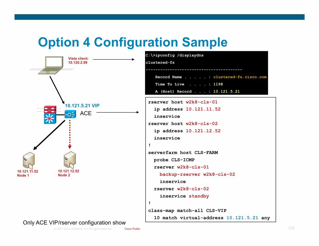
Option 4 Configuration Sample
10.121.5.21 VIP rserver host w2k8-cls-01 ip address 10.121.11.52 inservice rserver host w2k8-cls-02 ip address 10.121.12.52 inservice
! serverfarm host CLS-FARM probe CLS-ICMP rserver w2k8-cls-01 backup-rserver w2k8-cls-02 inservice rserver w2k8-cls-02 inservice standby
! class-map match-all CLS-VIP
10 match virtual-address 10.121.5.21 any
Vista client: 10.120.2.99
ACE
10.121.12.52 Node 2
10.121.11.52 Node 1
C:\>ipconfig /displaydns
clustered-fs
----------------------------------------
Record Name . . . . . : clustered-fs.cisco.com
Time To Live . . . . : 1198
A (Host) Record . . . : 10.121.5.21
Only ACE VIP/rserver configuration show

© 2007 Cisco Systems, Inc. All rights reserved. Cisco Public 125
Option 4 Results – Complete Automation
10.121.5.21 VIP
Vista client: 10.120.2.99
ACE
10.121.12.52 Node 2
10.121.11.52 Node 1
Probe Results:
--------------------- probe results -------------------- probe association probed-address probes failed passed health ------------------- ---------------+----------+----------+----------+------- serverfarm : CLS-FARM real : w2k8-cls-01[0] 10.121.11.52 1244 641 603 FAILED real : w2k8-cls-02[0] 10.121.12.52 988 454 534 SUCCESS
Connection Results (summary):
8 2 in TCP 5 10.120.2.99:51751 10.121.5.21:445 ESTAB 7 2 out TCP 5 10.121.12.52:445 10.121.5.17:1066 ESTAB
10.121.5.17 – inside NAT used for Server return
Waiting for cluster resources to come online (650MByte File Transfer during Node failure)

© 2007 Cisco Systems, Inc. All rights reserved. Cisco Public 126
Option 4 Summary
To prevent DNS issues it is imperative that the cluster service name is not allowed to be updated upon node change
Ensures that the VIP address is always present for the record One method is to use DNS record security so the cluster account cannot modify
the record
ACE in One-Arm or Routed mode can track and connect to servers in the local DC (across subnets) and also networks in other DC (multisite)
The ACE solution offers complete tracking of the cluster resource IP address and allows for failure/recovery of the nodes to occur with no user/admin intervention
If the primary DC goes down, therefore the ACE is gone, a ‘Tiered Recovery’ strategy can be used
Use Cisco ACE GSS (Global Site Selectors) to track the ACE VIP and if the VIP is down/unreachable, the GSS can modify DNS to allow clients to connect to cluster nodes in another DC location
OR A script or static configuration can be implemented for NAT in the network to
allow the clients to maintain the same DNS information but the NAT device can map the DNS record entry to the cluster nodes that are active in the standby DC

© 2007 Cisco Systems, Inc. All rights reserved. Cisco Public 127
Tiered Recovery One of Many Options
1. ACE Monitors Cluster 2. GSS Monitors ACE VIP
3. GSS Redirects to 2nd DC 4. NAT or ACE used to ‘hide’ new
Cluster Node
Data Center Data Center
ACE
GSS
NAT NAT
1
2 3
4

© 2007 Cisco Systems, Inc. All rights reserved. Cisco Public 128
Summary
Windows Server 2008 and Vista are coming to a network near you or will be soon – understand what the new TCP/IP stack does
IPv6 is on by default and preferred in both OS versions – this means that the OS can and will (in the right conditions) prefer IPv6 over IPv4 (even if it needs to use a tunnel)
WAAS still rules even though there are ‘some’ TCP improvements with the new Windows OS
Increased BW utilization of Vista/W2K8 will change the traffic profile on the network – be aware of this ahead of time
Ensure the ACE (or any other product doing TCP normalization or inspection) allows for the RFC 1323 options
L3/Multisite clusters are a great improvement – be aware of the default dependency on DNS and ensure the customer understands our solutions to the issue – we reduce client recovery time from minutes to seconds

© 2007 Cisco Systems, Inc. All rights reserved. Cisco Confidential Presentation_ID 129