deploying nexus 7000 in data center...
TRANSCRIPT

Deploying Nexus 7000 in Data Center Networks
Iqbal Syed Technical Marketing Engineer , Nexus 7000 - ECBU
BRKDCT-2951

This session is targeted to Network Engineers, Network Architects and IT administrators who have deployed or are considering the deployment of the Nexus 7000.
The session starts with a Nexus 7000 Overview and then primarily focuses on Data Center features and implementation best practices. The session also discusses some of the Data Center design examples. The Data Center feature overview and best practices section will cover features such as VDC, VPC, Layer-2 & Layer-3, Fabric Extenders, etc.
The session will cover NX-OS CLI very briefly at some places and so detailed CLI, implementation & troubleshooting is not part of this presentation’s scope.
Attendee should have a basic knowledge of the Nexus 7000 hardware platform and software features as well as good general knowledge of L2 and L3 protocols."

• Hardware Overview
• Feature Overview & Best Practices VDCs (Virtual Device Contexts)
Layer-2 Features
vPC (Virtual Port-Channel)
Fabric Path
FEX (Fabric Extender)
Layer-3 Features
OTV (Overlay Transport Virtualization)
Security Features
• Data Center Design Examples
• IOS – NX-OS Configuration Migration
• BRKDCT-2079 The Evolution of Data Center Networks
• BRKDCT-2023 Evolution of the Data Center Access Architecture
• BRKDCT-1044 FCoE Design, Operations and Mgmt Best Practices for the IP Network Engineer
• BRKDCT-5131 Mobility and Virtualization in the Data Center with LISP and OTV
• TECDCT-2001 Next Generation Data Centers

Enterprise
Core
DC Core
DC Aggregation
DC Access L2
STP, Port Security , BPDU Guard , L2 Port-Channel, FEX support, Fabric Path
L2 / L3 / DCI
L3 : FHRP, ARP , ND ,IGMP ,SVI , IGP , Services, VRF-lite
L2 : STP, L2 Port-Channel, vPC, VDC, FP
DCI: OTV, LISP
L3
BGP, IGP, BFD, Dual Stack, IPv6/v4 translation
MPLS P/PE , L3 Port-Channel , VDC
L3
L3: ISP Peering, VPN, BGP, IGP, BFD
MPLS P/PE , L3 Port-Channel , VDC
L2
L3

Collapsed DC Core / Enterprise Core
DC Aggregation
DC Access L2
STP, Port Security , BPDU Guard , L2 Port-Channel, FEX support, Fabric Path
L2 / L3 / DCI
L3 : FHRP, ARP ,ND ,IGMP , SVI , Services, IGP, VRF-lite
L2 : STP, L2 Port-Channel, vPC, VDC, FP
DCI: OTV, LISP
L3
L3: ISP Peering, VPN, BGP, IGP, BFD
MPLS P/PE , L3 Port-Channel , VDC, Dual Stack, IPv6/v4 translation
L2
L3

Enterprise
Core
Collapse DC Core / DC Aggregation
DC Access L2
STP, Port Security , BPDU Guard , L2 Port-Channel, FEX support, Fabric Path
L2 / L3 / DCI
L3 : FHRP, ARP , ND , IGMP , SVI , IGP , Services, BGP, VRF-lite, Routing Table
Scale, Dual Stack, IPv6/v4 translation, MPLS P/PE, L3 Port-Channel
L2 : STP, Vlan Scale , Bridging , L2 Port-Channel, vPC, VDC, FP
L3
L3: ISP Peering, VPN, BGP, IGP, BFD
MPLS P/PE , L3 Port-Channel , VDC
L2
L3

• Hardware Overview
• Feature Overview & Best Practices
VDCs (Virtual Device Contexts)
Layer-2 Features
vPC (Virtual Port-Channel)
Fabric Path
FEX (Fabric Extender)
Layer-3 Features
OTV (overlay Transport Virtualization)
Security Features
• Data Center Design Examples
• IOS – NX-OS Configuration Migration
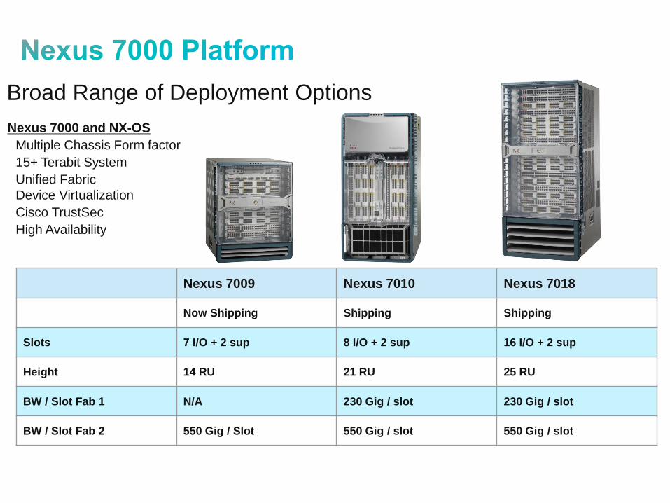
Broad Range of Deployment Options
Nexus 7000 and NX-OS
• Multiple Chassis Form factor
• 15+ Terabit System
• Unified Fabric
Device Virtualization
• Cisco TrustSec
• High Availability
Nexus 7009 Nexus 7010 Nexus 7018
Now Shipping Shipping Shipping
Slots 7 I/O + 2 sup 8 I/O + 2 sup 16 I/O + 2 sup
Height 14 RU 21 RU 25 RU
BW / Slot Fab 1 N/A 230 Gig / slot 230 Gig / slot
BW / Slot Fab 2 550 Gig / Slot 550 Gig / slot 550 Gig / slot

Power Supplies
Optional
front doors
Summary
LEDs
Integrated
Cable
Management
Supervisor
slots (1-2)
Crossbar
Fabric
Modules
Side-to-side
airflow
Locking
ejector
levers
I/O Slots
(3-9)
Fan Tray
Front Rear

Optional
locking front
doors
Front Rear
System status
LEDs
Integrated cable
management
with cover
Supervisor
slots (5-6)
I/O module slots
(1-4, 7-10)
Air intake with
optional filter
Air exhaust
Crossbar fabric
modules
System fan trays
Power supplies
Fabric fan trays
21RU
ID LEDs on
all FRUs
Front-to-
back airflow
Locking
ejector
levers
Common equipment
removes from rear
Two chassis
per 7’ rack
N7K-C7010
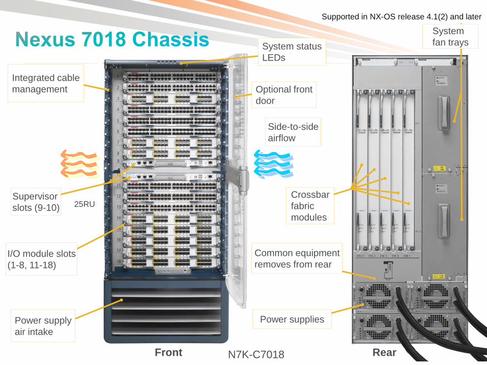
Front Rear
System status
LEDs
Integrated cable
management
Supervisor
slots (9-10)
Power supply
air intake
Crossbar
fabric
modules
Power supplies
25RU
Side-to-side
airflow
Common equipment
removes from rear
System
fan trays
I/O module slots
(1-8, 11-18)
Optional front
door
Supported in NX-OS release 4.1(2) and later
N7K-C7018

• Performs control plane and management functions
Dual-core 1.66GHz x86 processor with 8GB DRAM
2MB NVRAM, 2GB internal bootdisk, compact flash slots, USB
• Console, aux, and out-of-band management interfaces
• Interfaces with I/O modules via 1G switched EOBC
• Houses dedicated central arbiter ASIC that controls VOQ admission/fabric access via dedicated arbitration path to I/O modules
N7K-SUP1
ID LED
Console Port
AUX Port
Management
Ethernet
USB Ports CMP Ethernet
Reset Button Status
LEDs
Compact Flash
Slots

• Each fabric module provides 46Gbps per I/O module slot
Up to 230Gbps per slot with 5 fabric modules
• Different I/O modules leverage different amount of fabric bandwidth
80G per slot with 10G M1 modules
230G per slot with 10G F1 modules
• Access to fabric controlled using QoS-aware central arbitration with VOQ
N7K-C7018-FAB-1
N7K-C7010-FAB-1
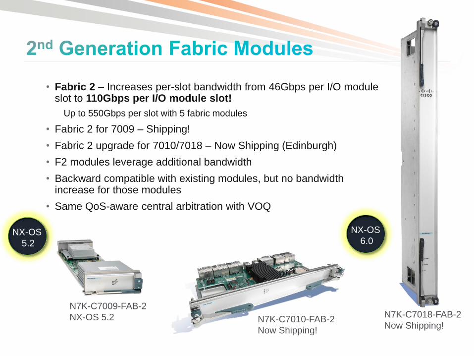
• Fabric 2 – Increases per-slot bandwidth from 46Gbps per I/O module slot to 110Gbps per I/O module slot!
Up to 550Gbps per slot with 5 fabric modules
• Fabric 2 for 7009 – Shipping!
• Fabric 2 upgrade for 7010/7018 – Now Shipping (Edinburgh)
• F2 modules leverage additional bandwidth
• Backward compatible with existing modules, but no bandwidth increase for those modules
• Same QoS-aware central arbitration with VOQ
N7K-C7018-FAB-2
Now Shipping! N7K-C7010-FAB-2
Now Shipping!
N7K-C7009-FAB-2
NX-OS 5.2
NX-OS
5.2
NX-OS
6.0

Per Slot
Investment Protection and Unified Fabric
Fabric Modules
46Gbps 92Gbps 138Gbps 184Gbps 230 Gbps
1GbE and 10GbE Modules

Per Slot
Investment Protection and Unified Fabric
Next Gen Fabric Modules (Fab 2)
110Gbps 220Gbps 330Gbps 440Gbps 550Gbps
10GbE, 40GbE and 100GbE Modules

230 Gbps 550 Gbps
Fab1 to Fab2 Migration - In-Service Upgrade
Fab2 supports all existing Modules
Fab2 makes the system ready for 40 and 100 GE Dense Modules
Anim
ate
d S
lide !
Per Slot
Fabric2
Fabric2
Fabric2
Fabric2
Fabric2
Fast.
Simple.
Non-Disruptive.
In-Service upgrade from
Fabric 1 to Fabric2
Fab2 is required to utilize
F2 Modules to full 48 port
10GE line rate capacity

• M family – L2/L3/L4 with large forwarding tables and rich feature set
• F family – Low-cost, high performance, low latency, low power and streamlined feature set
N7K-M108X2-12L N7K-M132XP-12/
N7K-M132XP-12L
N7K-M148GT-11/N7K-M148GT-11L
N7K-M148GS-11/N7K-M148GS-11L
N7K-F132XP-15 N7K-F248XP-25
Now Shipping

• 48-port 10G SFP+ I/O module
• 1G/10G dual-speed 2nd generation switch-on-chip (SoC) design
• Layer 2 and Layer 3 forwarding with L3/L4 services (ACL/QoS/Sampled NetFlow)
32K FIB TCAM
• Multi-protocol – Classic Ethernet, FabricPath, DCB/FCoE**
• Fabric Extender FEX-link support
• 16 SPAN Sessions**
• Compatible with Nexus 7000 FAB1 or FAB2
F2 with Fab-1 – 230Gbps available to I/O Module
F2 with Fab-2: 480Gbps available to I/O Module
• All ports wire rate with local switching
• Throughput:
480G/slot, 714Mpps/slot
• 4-5µsec latency
N7K-F248XP-25
NX-OS 6.0(x)
*
*VDC License not required when there are only F2 series in the chassis, It will be required when Chassis also contains M/F1series
**FCOE and 16 SPAN sessions not supported at first release

M1 Series (Service Rich)
F1 Series (Performance)
F2 Series (Performance)
L2 Table 128K 16K-256K 16K-192K
L3 (IPv4, IPv6) Yes No* Yes
Netflow Full No No
ACL Up to 128K 1K-16K 16K-192K
FabricPath No Yes Yes
Buffer per line-rate 10G port Up to 176MB/port 2.3MB/port 2.5MB/port
Forwarding capacity per module 60-120Mpps 480Mpps 714Mpps
Bandwidth capacity per module Up to 80G/slot Up to 230G/slot Up to 480G/slot
Line-rate 10G ports (18 slot) 128 512 768
Latency (unicast local switching @ 64 bytes)
9.5 μsec 4.7 μsec 5.8 μsec
Power budget per line-rate 10G port 81W/port 12W/port 10W/port
* Can leverage M1 modules in same system for L3
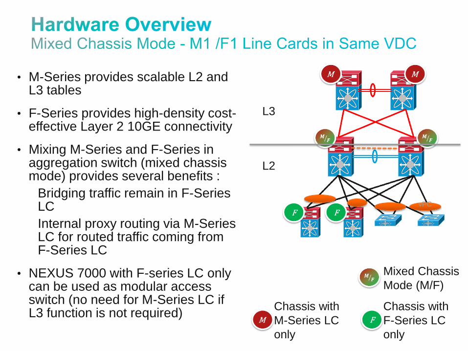
• M-Series provides scalable L2 and L3 tables
• F-Series provides high-density cost-effective Layer 2 10GE connectivity
• Mixing M-Series and F-Series in aggregation switch (mixed chassis mode) provides several benefits :
Bridging traffic remain in F-Series LC
Internal proxy routing via M-Series LC for routed traffic coming from F-Series LC
• NEXUS 7000 with F-series LC only can be used as modular access switch (no need for M-Series LC if L3 function is not required)
L3
L2
Mixed Chassis
Mode (M/F)
Chassis with
F-Series LC
only
Chassis with
M-Series LC
only
vPC
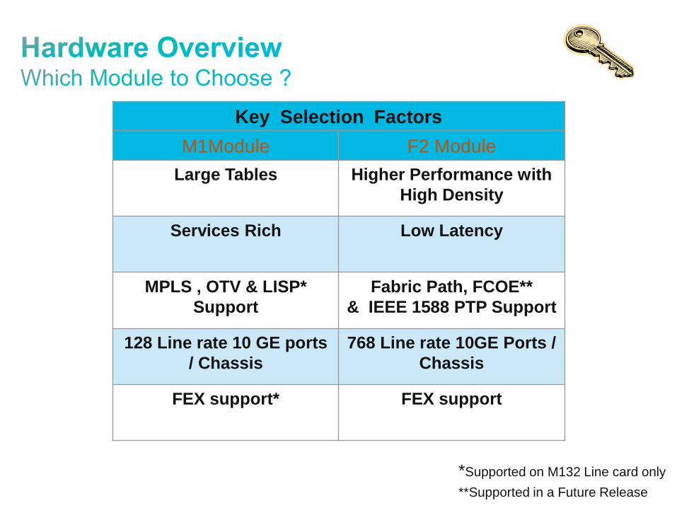
Key Selection Factors
M1Module F2 Module
Large Tables Higher Performance with
High Density
Services Rich Low Latency
MPLS , OTV & LISP*
Support
Fabric Path, FCOE**
& IEEE 1588 PTP Support
128 Line rate 10 GE ports
/ Chassis
768 Line rate 10GE Ports /
Chassis
FEX support* FEX support
*Supported on M132 Line card only
**Supported in a Future Release

• Hardware Overview
• Feature Overview & Best Practices VDCs (Virtual Device Contexts)
Layer-2 Features
vPC (Virtual Port-Channel)
Fabric Path
FEX (Fabric Extender)
Layer-3 Features
OTV (Overlay Transport Virtualization)
Security Features
• Data Center Design Examples
• IOS – NX-OS Configuration Migration

• VDCs provide logical separation of control-plane, data-plane, management, resources, and system processes within a physical switch
Support up to 4 separate virtual switches (4 VDCs) from a single physical chassis with common supervisor module(s)
Infrastructure Kernel
VDC 1
VDC 3
VDC 4
Layer 3 Protocols
OSPF
BGP
EIGRP
GLBP
HSRP
IGMP
PIM SNMP
…
VDC 1, 2, 3 or 4
Layer 2 Protocols
VLAN
PVLAN
UDLD
CDP
802.1X STP
LACP CTS
…
VDC
Extranet
VDC
Prod
VDC
DMZ
Appropriate for typical silo designs such as:
Production, Dev, Test
Intranet, DMZ, Extranet
Organization A, B C
Application A, B, C
Customer A, B, C
Enables collapsing of multiple logical networks into
single physical infrastructure & helps scale physical
resources of device

Resources that can only be allocated, set, or configured
globally for all VDCs from the master VDC – i.e; boot image
configuration, Ethanalyzer session, SPAN, CoPP etc
Resources that are allocated to a particular VDC – e for
example L2 and L3 ports, VLANs, IP address space, etc…
Some resources are shared between VDCs – for example :
the OOB Ethernet management port.
Global
Resources
Dedicated
Resources
Shared
Resources
m4route-mem Set ipv4 route memory limits
m6route-mem Set ipv6 route memory limits
module-type Controls which type of modules are allowed in this vdc
monitor-session Monitor local/erspan-source session
monitor-session-erspan-dst Monitor erspan destination session
port-channel Set port-channel limits
u4route-mem Set ipv4 route memory limits
u6route-mem Set ipv6 route memory limits
vlan Set VLAN limits
vrf Set vrf resource limits
Certain resources can be allocated and limited to a given VDC:
http://www.cisco.com/en/US/prod/collateral/switches/ps9441/ps9402/ps9512/White_Paper_Tech_Overview_Virtual_Device_Contexts.html
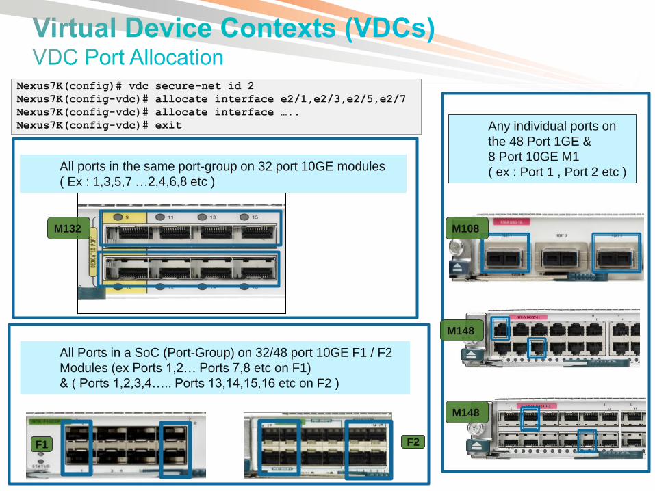
Nexus7K(config)# vdc secure-net id 2
Nexus7K(config-vdc)# allocate interface e2/1,e2/3,e2/5,e2/7
Nexus7K(config-vdc)# allocate interface …..
Nexus7K(config-vdc)# exit
All ports in the same port-group on 32 port 10GE modules
( Ex : 1,3,5,7 …2,4,6,8 etc )
M132
All Ports in a SoC (Port-Group) on 32/48 port 10GE F1 / F2
Modules (ex Ports 1,2… Ports 7,8 etc on F1)
& ( Ports 1,2,3,4….. Ports 13,14,15,16 etc on F2 )
F1 F2
Any individual ports on
the 48 Port 1GE &
8 Port 10GE M1
( ex : Port 1 , Port 2 etc )
M108
M148
M148

If the same VDC has both M1 and M1-XL modules, the system will operate with the least common denominator mode
Customize VDC resource-limit module-type as needed (ex. Does not allow M1 modules for internet facing VDC)
Nexus7K(config)# vdc inet
Nexus7K(config-vdc)# limit-resource module-type m1xl
VDC2 INET
VDC1 Admin
VDC3 ENET
INET Facing
VDC
M1-XL
modules only
Lab VDC
M1 Modules
only
Default VDC mode allows M1 / M1-XL / F1 Modules Other dedicated modes(ex:F1 ,M1 ,M1-XL & F2 only) are configurable
VDC2
VDC3 Communication Between VDCs
Must use front panel port to communicate between VDCs
No soft cross-connect or backplane inter-VDC communication
It is recommended to allocate whole modules per VDC,
Helps with better hardware resource scaling
• Hardware Overview
• Feature Overview & Best Practices VDCs (Virtual Device Contexts)
Layer-2 Features
vPC (Virtual Port-Channel)
Fabric Path
FEX (Fabric Extender)
Layer-3 Features
OTV (Overlay Transport Virtualization)
Security Features
• Data Center Design Examples
• IOS – NX-OS Configuration Migration

It is recommended is to enable UDLD normal mode globally
Enabling UDLD feature is equivalent to configuring UDLD normal mode globally
Default message timer is recommended Nexus7K(config)#
feature udld
Tx
Rx
Tx
Rx
UDLD has 2 modes of operation : normal or aggressive
Normal : UDLD detects the link error by examining the incoming UDLD packets from the peer port. In case of error, UDLD will errdisable the port.
Aggressive : Set port to err-disable state in case of sudden cessation of udld packets .Port is placed in err-disable mode if no udld packets are received for 3 x hello + 5 sec =50 seconds (default hello-interval is 15 sec)
UDLD is a light-weight Layer 2 protocol that detects and disables one-way connections

Implement one of the following methods to prevent double encapsulation 802.1Q attack
Assign unused VLAN as native VLAN (consistent across the same L2)
Clear native VLAN from the trunk
Configure to tag the native VLAN on all trunks Nexus7K(config)# vlan dot1Q tag native
Nexus7K# show interface status err-disabled
Nexus7K(config)# errdisable recovery cause <cause>
Nexus7K(config)# errdisable recovery interval <time>
It is recommended to manually bring up error-disabled interface after the cause is identified
Errdisable recovery is disabled by default
Implement storm-control on L2 host ports and access layer to prevent disruptions caused by broadcast and multicast storm
Unsupported Layer-2 features
DTP, ISL Trunk, Flexlink, Link-State Tracking

Active
Utilize LACP to negotiate both L2 and L3 port-channels
N7010-2 N7010-1 BPDUs
ON Root
Active
N7010-2 N7010-1
ON L3 Po is
down !
L3 Po
is up
BPDUs Nexus7K(config)# feature lacp
Nexus7K(config)# int e<mod>/<port>
Nexus7K(config-if)# channel-group <#> mode active
Dispute!
Mismatch Conditions
Nexus7K(config)#
Shut
no lacp graceful-convergence
no shut
Nexus7K(config)#
Shut
no lacp suspend-individual
no shut
Disable LACP suspend-individual only on “edge” port-channel
Nexus7K(config-if-range)# lacp rate normal
Disable LACP “graceful-convergence” on port-channel if “graceful-convergence” interoperability is an issue
If required, disable LACP “suspend-individual” on port-channel interface to allow the individual member ports to operate as “individual”
Implement port channels with 2, 4 ,8 or 16 members for optimal traffic distribution
Understand LACP compatibility enhancements
Implement normal LACP timer in a dual supervisor system (default)

Understand port-channel failure behaviors
BW and IGP cost for L3 channel are recalculated when physical member fails
STP cost for L2 channels does not recalculate when physical member fails
Nexus7K#sh port-channel load-balance forwarding-path interface port-channel 1 src-ip 1.1.1.1 dst-ip 2.2.2.2 vlan 2 mod 3
Missing params will be substituted by 0's.
Module 3: Load-balance Algorithm: source-dest-ip-vlan
RBH: 0x7 Outgoing port id: Ethernet3/3
OSPF Cost
50 100
50
Access
Aggr1a Aggr1b
Core1-1 Core-2
Statically configure IGP cost on L3 channel if the default behavior is not desired
Modify port-channel load-balancing to match needs
Configure on default VDC and the default is Source-Destination-IP
Nexus7K(config)# port-channel load-balance ethernet <lb-method>
Nexus7K(config)# port-channel load-balance ethernet <lb-method> module <mod>
PAgP is not supported
Min-link Max-link is supported as of 5.1
Nexus7K# sh port-channel load-balance

• Port-channel with M1 and M1-XL member interfaces is supported
• Port-channel with M1 ports on one side and F1 / F2 ports on the other side is supported
• Mixing M1/M1-XL and F1 interfaces in a single port-channel is not allowed
• F1 LCs support up to 16 active member ports and M1 LCs support 8 active member ports in a port-channel
M1 LCs has 8 has buckets, F1 LCs has 256 hash buckets
Traffic forwarded from an M1/M1-XL module to the F1 channel will map to no more than 8 of the member ports
Traffic forwarded from an F1 module to the M1/M1-XL channel can map to any of the 8 member ports
F2 LC supports Port-channel with F2 on one end and M1/F1 on the other end of the Port-channel
M1 M1
F1 F1
M1
F1
M1
F1
M1 F1
F2
F2
M1
M1

• Implement consistent STP mode in the same L2 domain
RPVST+ is the default and is backward compatible with PVST
Nexus7K# sh spanning-tree active | i Peer Po11 Desg FWD 12 128.4106 P2p Peer(STP)
Nexus7K# show spanning-tree summary total
----deleted----
Name Blocking Listening Learning Forwarding STP Active
---------- -------- --------- -------- --------- ---------
9 vlans 0 0 0 18 18
Total number of
logical ports
Nexus7K# sh spanning-tree active | i Bound
Po11 Desg FWD 100000 128.4106 P2p Bound(PVST)
Utilize MST to scale large L2 network
MST supports 75K logical ports (90K in NX-OS 5.0) and RPVST+ supports 16K logical ports
MST introduces some complexity and requires proper planning
MST interoperates with both RPVST+ and PVST+ by utilizing PVST+ simulation
3 msts 2 0 0 8 10 MST ports
Configure to only allow needed VLANs on trunk interfaces

• Implementing STP long path-cost method
RSTP default is short and MST default is long
• Utilize port-profiles to enforce consistent configuration
Nexus7K(config)# port-profile type ethernet host-port
state enable
switchport
switchport mode access
spanning-tree port type edge
spanning-tree bpduguard enable
Nexus7K(config-if)#
switchport inherit port-profile host-port
switchport access vlan 100-110
Nexus7K(config)# port-profile type ethernet trunk-port
state enable
switchport
switchport mode trunk
switchport trunk native vlan 100
spanning-tree port type network
Nexus7K(config-if)#
switchport inherit port-profile trunk-port
switchport trunk allow vlan 100-110
Note: Port-Profiles are live profiles (modify or
delete port-profiles will be reflected on the
assigned interfaces)
Nexus7K(config)# spanning-tree pathcost method long
Unsupported STP features
PVST+
Nexus7K# sh run int e10/11 expand-port-profile

• Determine the maximum number of MST instances
• Develop the VLAN plan
• Map the entire ranges of VLANs to pre-determined MST instances
• Use one instance of MST for vPC vlans
agg1a agg1b
Acc1
instance VLANs mapped
IST 0 1-100
MSTI 1 101-200
MSTI 2 201-300
… ….
MSTI 40 4001-4094
Primary
root
IST 0,1,3
Primary
root
IST 2,4
IST1
IST2
IST2
IST1
IST3
Acc2
Nexus7K#
spanning-tree mst configuration
instance 1 vlan 101-200
instance 2 vlan 201-300
. . . . . . . . .
instance 40 vlan 4001-4094
name ILUVSTP
revision 1
!
spanning-tree mode mst
VLAN numbers are provided as an example
Plan ahead to avoid future MST
configuration changes
Aggregation
Access
Data Center Core B
R
N
E
BPDUguard
Rootguard
Network port
Edge or portfast port type
- Normal port type
B
R R R R R R R R
B
E
B B
E
B
E
Layer 3
Layer 2 (STP + Rootguard)
Layer 2 (STP + BPDUguard)
E
Secondary
Root
HSRP
STANDBY
Primary
Root
HSRP
ACTIVE
E
Primary
vPC
Secondary
vPC
vPC
Domain
UDLD (recommendation
: NORMAL mode)
N N
- - - - - - - -
- - - -
- -
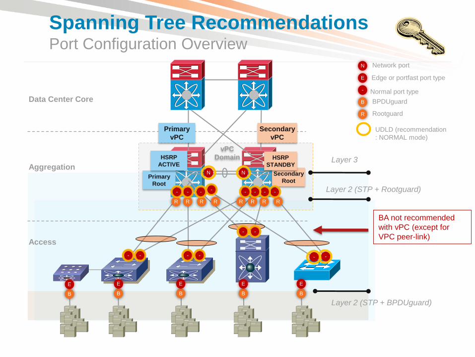
Spanning Tree Recommendations Port Configuration Overview
BA not recommended
with vPC (except for
VPC peer-link)
- -

• Hardware Overview
• Feature Overview & Best Practices VDCs (Virtual Device Contexts)
Layer-2 Features
vPC (Virtual Port-Channel)
Fabric Path
FEX (Fabric Extender)
Layer-3 Features
OTV (Overlay Transport Virtualization)
Security Features
• Data Center Design Examples
• Nexus 7000 Migration Strategies

MCEC
! Enable vpc on the switch
dc11-7010-1(config)# feature vpc
! Check the feature status
dc11-7010-1(config)# show feature | include vpc
vpc 1 enabled
vPC Peers
vPC allows a single device to use a port channel across two neighbor switches (vPC peers) (Layer 2 port channel only)
Eliminate STP blocked ports & reduces STP Complexity (Do not disable STP)
• Uses all available uplink bandwidth - enables dual-homed servers to operate in active-active mode
• Provides fast convergence upon link/device failure
• If HSRP enabled, both vPC devices are active on forwarding plane
Available since NX-OS 4.1(3) on the Nexus 7000 & NX-OS 4.1(3)N1 on N5K
MCEC
vPC Peers
vPC_PL
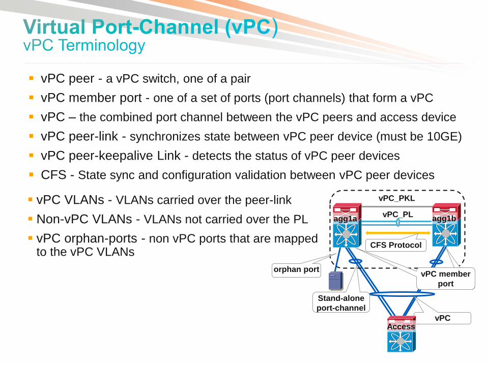
vPC VLANs - VLANs carried over the peer-link
Non-vPC VLANs - VLANs not carried over the PL
vPC orphan-ports - non vPC ports that are mapped to the vPC VLANs
vPC_PKL
vPC
vPC member
port
agg1a
Access
agg1b CFS Protocol
agg1b agg1a
vPC peer - a vPC switch, one of a pair
vPC member port - one of a set of ports (port channels) that form a vPC
vPC – the combined port channel between the vPC peers and access device
vPC peer-link - synchronizes state between vPC peer device (must be 10GE)
vPC peer-keepalive Link - detects the status of vPC peer devices
CFS - State sync and configuration validation between vPC peer devices
orphan port
Stand-alone
port-channel

• Do not disable STP !!
• Configure vPC peers in aggregation layer as primary/secondary root
• BA (Bridge Assurance) is enabled by default on vPC peer-link
• Do not enable Loopguard and BA on vPC (disabled by default)
• Enable STP port type “edge” and port type “edge trunk” on host ports
• Enable STP BPDU-guard globally on access switches
• Selectively allow vlans on trunks
BPDU-guard BPDU-guard
Port Type
Edge / Edge Trunk
agg1b agg1a
BA Enabled
(Default)
No BA, Loopguard
(Default)
VLAN 1- 4094
STP Pri 16384
No BA or Loopguard
(Default)
VLAN 1 - 4094
STP Pri 8192
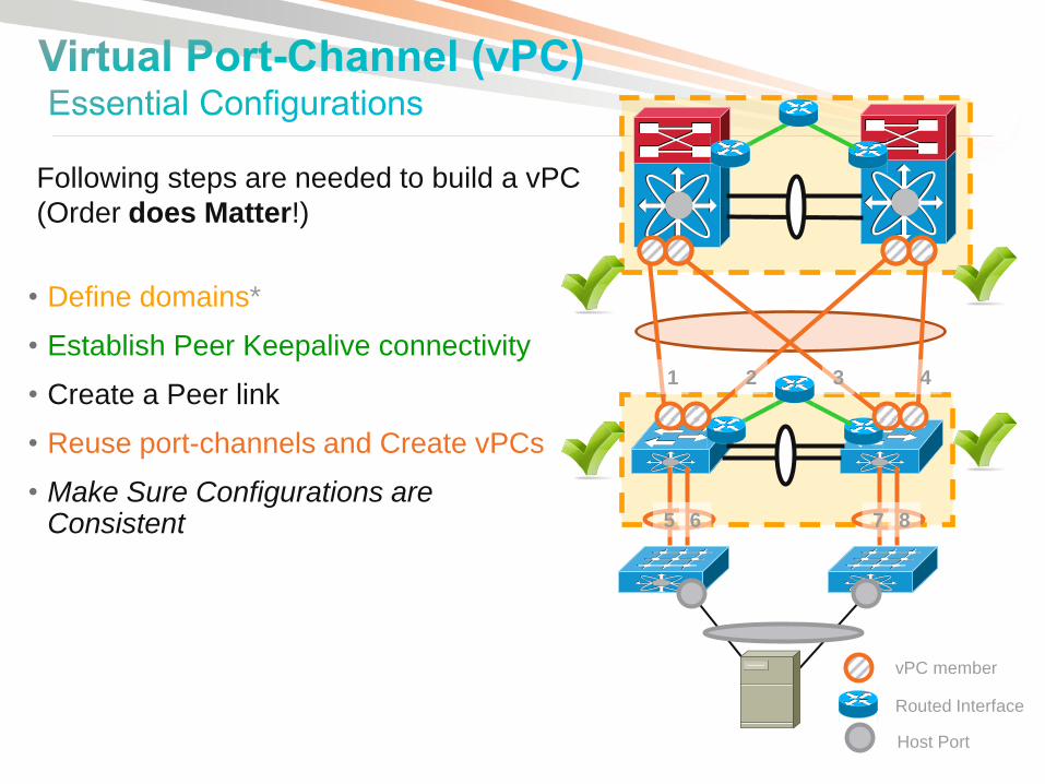
• Define domains*
• Establish Peer Keepalive connectivity
• Create a Peer link
• Reuse port-channels and Create vPCs
• Make Sure Configurations are Consistent 5 6 7 8
1 2 3 4
Following steps are needed to build a vPC
(Order does Matter!)
vPC member
Routed Interface
Host Port

Strong Recommendations
Designate vPC primary / secondary peer device
Implement IGP routing between vPC peers
Enable vPC peer-gateway
Enable vPC auto-recovery
Enable vPC ARP Sync
agg1b agg1a
vPC Auto-
recovery
vPC_PL
vPC_PKL
vPC Auto-
recovery
vPC ARP
Sync
vPC ARP
Sync
routing peer
Enable Peer-
Gateway
Enable
Peer-
Gateway
vPC
Secondary
role pri 16384 vPC Primary
role pri 8192
Optional Recommendations
Enable peer-switch in a pure vPC topology
Enable Orphan port-suspend if needed
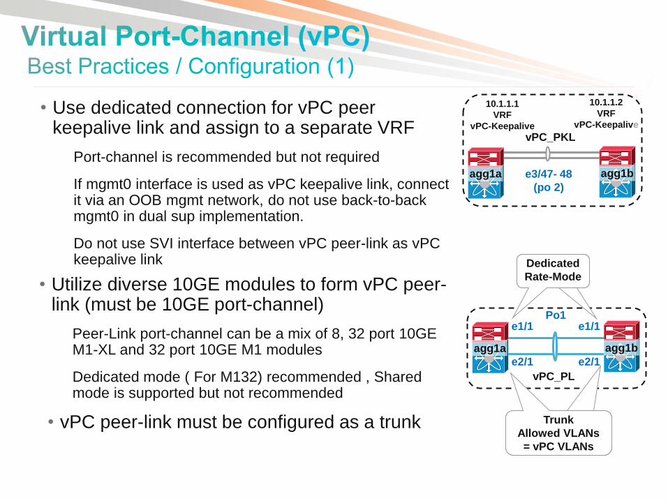
• Use dedicated connection for vPC peer keepalive link and assign to a separate VRF
Port-channel is recommended but not required
If mgmt0 interface is used as vPC keepalive link, connect it via an OOB mgmt network, do not use back-to-back mgmt0 in dual sup implementation.
Do not use SVI interface between vPC peer-link as vPC keepalive link
agg1b agg1a
vPC_PKL
e3/47- 48
(po 2)
10.1.1.1
VRF
vPC-Keepalive
10.1.1.2
VRF
vPC-Keepalive
• Utilize diverse 10GE modules to form vPC peer-link (must be 10GE port-channel)
Peer-Link port-channel can be a mix of 8, 32 port 10GE M1-XL and 32 port 10GE M1 modules
Dedicated mode ( For M132) recommended , Shared mode is supported but not recommended
• vPC peer-link must be configured as a trunk
agg1b agg1a
vPC_PL
e1/1 e1/1
e2/1 e2/1
Po1
Dedicated
Rate-Mode
Dedicated
Rate-Mode
Trunk
Allowed VLANs =
vPC VLANs
Trunk
Allowed VLANs
= vPC VLANs
vPC_PKL
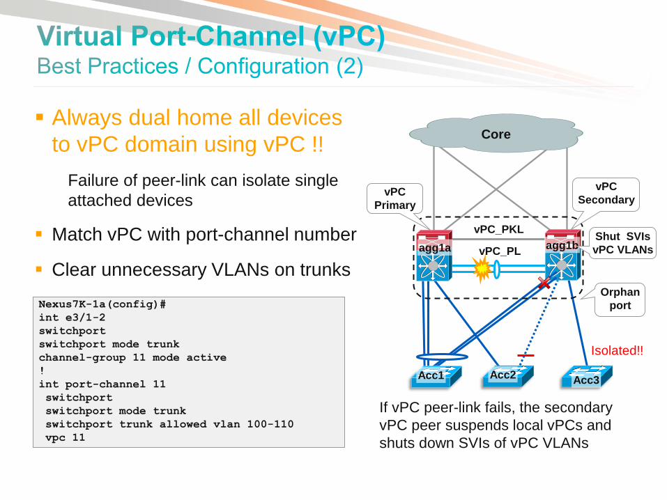
Always dual home all devices
to vPC domain using vPC !!
Failure of peer-link can isolate single
attached devices
Match vPC with port-channel number
Clear unnecessary VLANs on trunks
Nexus7K-1a(config)#
int e3/1-2
switchport
switchport mode trunk
channel-group 11 mode active
!
int port-channel 11
switchport
switchport mode trunk
switchport trunk allowed vlan 100-110
vpc 11
agg1b
Isolated!!
Acc1
Core
vPC
Secondary vPC
Primary
vPC_PL
Shut SVIs
vPC VLANs
Acc3
Orphan
port
Acc2
agg1a
If vPC peer-link fails, the secondary
vPC peer suspends local vPCs and
shuts down SVIs of vPC VLANs
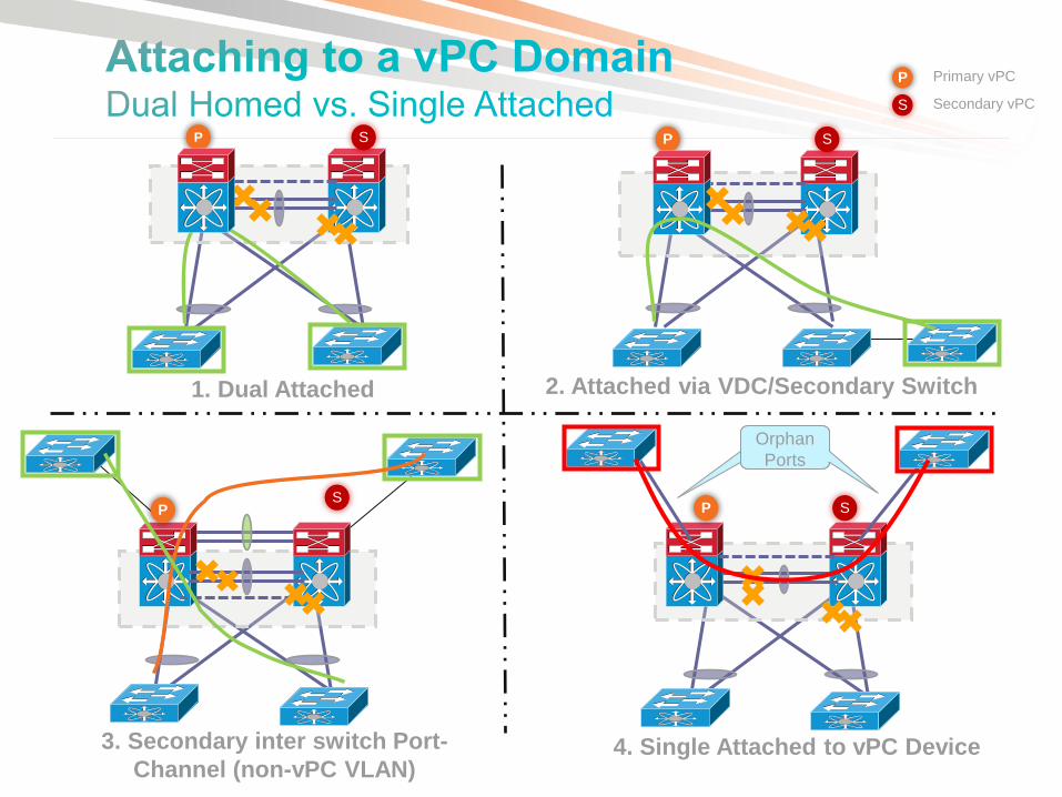
S P
3. Secondary inter switch Port-
Channel (non-vPC VLAN)
Orphan
Ports
Orphan
Ports
S P
4. Single Attached to vPC Device
S P
2. Attached via VDC/Secondary Switch
S P
1. Dual Attached
Primary vPC
Secondary vPC S
P

agg1b
vPC Secondary
role priority
16382
agg1a
vPC Primary
(role priority
8192)
Acc1b Acc1a
vPC Primary
role priority
8192
vPC Secondary
role priority
16384
For better vPC Management & Troubleshooting :
Assign and designate vPC primary peer role with lower role priority
Align vPC primary peer with STP primary root, HSRP active router and PIM DR
One vPC peer can be configured as HSRP active router for all VLANs since both vPC devices are active forwarders
STP Primary
root & HSRP
active router
Implement IGP routing between vPC peers to re-route traffic in case of complete uplink failure
A point-to-point routing VLAN over vPC peer-link between the vPC peers is supported
Alternatively, create a dedicated L3 port-channel or leverage a non-VPC trunk to perform routing between vPC peers
Routing Peer
(vlan 99)
agg1b agg1a
vPC_PL
e2/1
e1/1
e2/1
e1/1

vPC Peer-Gateway
• Configure “peer-gateway” to enable vPC peer devices to act as the gateway for packets destined to the vPC device’s router-MAC address
Necessary for devices which reply to sender’s mac-address instead of HSRP virtual mac-address
Traffic forwards locally and does not traverse the peer-link
Nexus7K(config-vpc-domain)# peer-gateway
Note: Disable IP redirects on all interface-vlans of this vPC domain for correct operation of this feature
vPC Peer-
Gateway
Peer-
Gateway
No IP
redirects
No IP
redirects
Nexus7K(config-vpc-domain)#peer-gateway exclude-vlan 99
Warning:
!! Overwrites previous peer-gateway config !!
agg1b agg1a
§ Disable IP redirects on all SVIs of the vPC VLANs ( Default with 5.1)
§ Exclude inter-switch routing VLAN on vPC peer-link from peer-gateway function (NX-OS 5.1.3), required on mixed-chassis with F1 peer-links to avoid traffic punt to CPU for tunneling (can be configured with M1 peer-link but not required)
Routing Peer
(vlan 99)
vPC Peer-
Gateway
Peer-Gateway
exclude-vlan 99
DST-MAC
= Agg1a
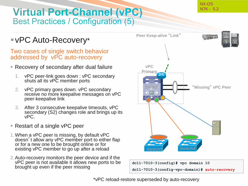
vPC Auto-Recovery*
Two cases of single switch behavior addressed by vPC auto-recovery
Recovery of secondary after dual failure
1. vPC peer-link goes down : vPC secondary shuts all its vPC member ports
2. vPC primary goes down. vPC secondary receive no more keepalive messages on vPC peer-keepalive link
3. After 3 consecutive keepalive timeouts, vPC secondary (S2) changes role and brings up its vPC.
Restart of a single vPC peer
1.When a vPC peer is missing, by default vPC doesn’t allow any vPC member port to either flap or for a new one to be brought online or for existing vPC member to go up after a reload
2.Auto-recovery monitors the peer device and if the vPC peer is not available it allows new ports to be brought up even if the peer missing
Switch3
Switch
1
Switch4
vPC
Primary
Peer Keep-alive “Link”
“Missing” vPC Peer
dc11-7010-3(config)# vpc domain 10
dc11-7010-3(config-vpc-domain)# auto-recovery
NX-OS
N7K - 5.2
*vPC reload-restore superseded by auto-recovery
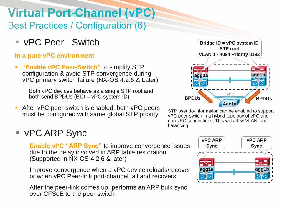
vPC Peer –Switch
In a pure vPC environment,
“Enable vPC Peer-Switch” to simplify STP configuration & avoid STP convergence during vPC primary switch failure (NX-OS 4.2.6 & Later)
Both vPC devices behave as a single STP root and both send BPDUs (BID = vPC system ID)
After vPC peer-switch is enabled, both vPC peers must be configured with same global STP priority
vPC
agg1b agg1a
Acc1a
STP root pri 8192 Bridge ID = vPC system ID
STP root
VLAN 1 - 4094 Priority 8192
BPDUs BPDUs
STP pseudo-information can be enabled to support vPC peer-switch in a hybrid topology of vPC and non-vPC connections .This will allow VLAN load-balancing
vPC ARP Sync
Enable vPC “ARP Sync” to improve convergence issues due to the delay involved in ARP table restoration (Supported in NX-OS 4.2.6 & later)
Improve convergence when a vPC device reloads/recover or when vPC Peer-link port-channel fail and recovers
After the peer-link comes up, performs an ARP bulk sync over CFSoE to the peer switch
agg1b agg1a
vPC ARP
Sync
vPC ARP
Sync

CE-1
S2-Secondary S1 -Primary
vPC peer-link
vPC 1
po1
Keepalive
vPC Graceful Type-1 Check
Both peers must have identical parameters
Inconsistencies in such parameters results in all vlans on
both vpc legs coming down
With graceful type-1 check, only Secondary vPC
members are brought down & vPC member ports on
primary peer device remain up
(Not applicable for dual homed FEX )
S1(config-vpc-domain)# graceful
consistency-check
S2(config-vpc-domain)# graceful
consistency-check
Graceful Type-1 & Per-Vlan Type-1
checks enabled by default.
Type-1 Inconsistency
NX-OS
N7K - 5.2
Per-Vlan Type-1 Consistency
Currently if STP vlans enabled on vPC peers do not
match, it is a global type-1 inconsistency - Will result in
vPC peer-link and all vPCs on both peers coming down
With Per-vlan type-1 check, spanning-tree vlans that do
not match on both peers, will be brought down on all
vPCs and peer-link. Other vlans will stay up
(Not applicable for MST Mode )

vPC Supported Server fails over
correctly
Active/Standby Server does not fail
over correctly
vPC vPC Orphan-Ports Suspend
A vPC orphan port is an non-vPC interface on a switch where other ports in the same VLAN are configured as vPC interfaces
vPC orphan ports have historically been problematic for mixed server topologies
Prior to release 5.2 on Nexus 7000 an orphan port was ‘not’ shut down on loss of vPC peer-links
With 5.2 , the orphan ports on the vPC secondary peer can (configurable) also be shut down triggering NIC teaming recovery
Configuration is applied to the physical port
N7K-2(config)# int eth 100/1/1
N7K-2(config-if)# vpc orphan-ports suspend
NX-OS
N7K - 5.2
eth 100/1/1

• Dynamic routing between external L3 devices and vPC peers over L3 routed interfaces is supported
Routing
peer
Routing
peer
agg1b agg1a
routing
peer
routing
peer
vPC_PKL
vPC_PL
L3 L3
L3 L3
Dynamic routing between vPC peers over point-to-point VLAN across vPC peer-link is supported
agg1b agg1a
vPC_PKL
vPC_PL
Routing peer
Dynamic routing between external L3 devices and vPC peers over non-vPC VLANs is supported
L3 link
L2 link
agg1b agg1a
L3 FW
vPC_PKL
vPC_PL
Non-VPC
VLANs
Routing
peer
Routing
peer
L2 L2
agg2b agg2a
vPC_PL
vPC_PKL
agg1b agg1a vPC_PL
vPC_PKL
vPC
routing
peer
vPC
L3 link
L2 link
vPC
routing
peer
vPC
agg1b agg1a
vPC_PL
vPC_PKL
vPC
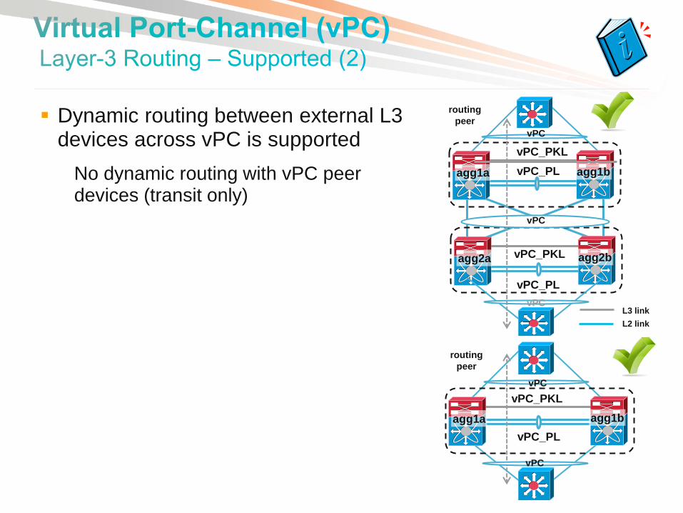
Dynamic routing between external L3 devices across vPC is supported
No dynamic routing with vPC peer devices (transit only)

• When routing to vPC peer devices over vPC or vPC VLAN, configure static routes to FHRP address
If the static routes point to the hardware mac-address, ensure “vPC peer-gateway” is enabled
Static
route
vPC
agg1b agg1a
L3 FW
vPC
vPC_PKL
vPC_PL
agg1b agg1a
L3 FW
vPC_PKL
vPC_PL
VPC VLANs
L2 L2
Static
route
Static
route
L3 link
L2 link
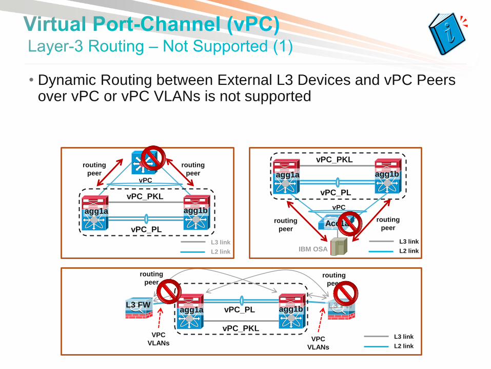
• Dynamic Routing between External L3 Devices and vPC Peers over vPC or vPC VLANs is not supported
routing
peer
routing
peer vPC
agg1b agg1a vPC
agg1b agg1a
Acc1a routing
peer
routing
peer
routing
peer routing
peer
agg1b agg1a L3 FW L3 FW
VPC
VLANs
VPC
VLANs
IBM OSA
vPC_PL
vPC_PKL vPC_PL
vPC_PKL
vPC_PKL
vPC_PL
L3 link
L2 link
L3 link
L2 link
L3 link
L2 link

• Dynamic routing between vPC peer devices over vPC interconnection is not supported
agg2b agg2a
Routing
peer
vPC_PL
vPC_PKL
agg1b agg1a vPC_PL
vPC_PKL
vPC Routing
peer
L3 link
L2 link
• Hardware Overview
• Feature Overview & Best Practices VDCs (Virtual Device Contexts)
Layer-2 Features
vPC (Virtual Port-Channel)
Fabric Path
FEX (Fabric Extender)
Layer-3 Features
OTV (Overlay Transport Virtualization)
Security Features
• Data Center Design Examples
• IOS – NX-OS Configuration Migration

-All Links Active
Traditional Spanning Tree Based Network
Up to 16 Agg
switches
-Blocked Links
Cisco FabricPath Network
160+ Tbps
switching capacity
Eliminate Spanning tree limitations
Multi-pathing across all links, high cross-sectional bandwidth
High resiliency, faster network re-convergence
Any VLAN, any where in the fabric eliminate VLAN Scoping
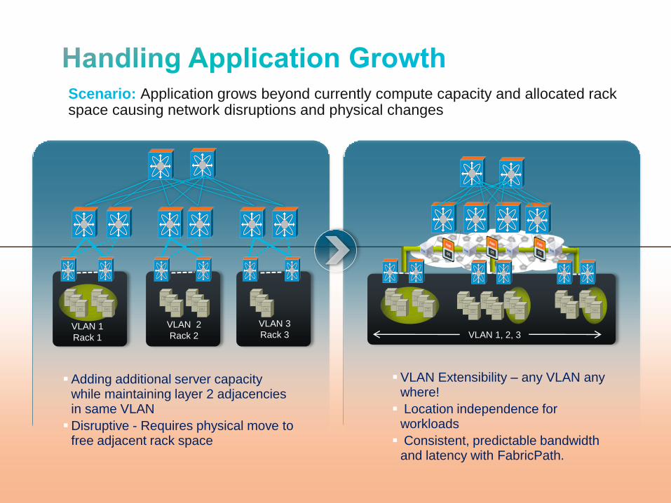
Scenario: Application grows beyond currently compute capacity and allocated rack space causing network disruptions and physical changes
VLAN 1, 2, 3 VLAN 1
Rack 1
VLAN 2
Rack 2
VLAN 3
Rack 3
VLAN Extensibility – any VLAN any where!
Location independence for workloads
Consistent, predictable bandwidth and latency with FabricPath.
Adding additional server capacity while maintaining layer 2 adjacencies in same VLAN
Disruptive - Requires physical move to free adjacent rack space

N7K(config)# feature-set fabricpath
N7K(config)# fabricpath switch-id <#>
N7K(config)# interface ethernet 1/1
N7K(config-if)# switchport mode fabricpath
• No L2 IS-IS configuration required
• Single control protocol for unicast, multicast, vlan pruning
L2 Fabric
FabricPath Port
CE Port
1/1

Shortest path, Multi-Pathing, High-availability
A
L1
L2
S1 S2 S3 S4
S11 S12 S42
L2 Fabric
L3
L4
B
Switch IF
… …
S42 L1, L2, L3, L4
• Shortest path for low latency • Up to 256 links active between any 2 nodes • High availability with N+1 path redundancy

• Hardware Overview
• Feature Overview & Best Practices VDCs (Virtual Device Contexts)
Layer-2 Features
vPC (Virtual Port-Channel)
Fabric Path
FEX (Fabric Extender)
Layer-3 Features
OTV (Overlay Transport Virtualization)
Security Features
• Data Center Design Examples
• IOS – NX-OS Configuration Migration

Nexus 2000 (FEX) can be considered as a remote I/O module for the Nexus 7000
• Provide High Density GE Connectivity
• Support Hybrid ToR and EoR Network Architectures
FEX physically resides on top of each server rack but logically acts as an end of access row device
• Reduced Power Consumption/Cap-EX/Op-EX
• Single point of Management
No configuration and software on FEX to manage
FEX SW Per
System
2248TP-1GE 5.1(1) and later
32
2224TP-1GE 2232PP-10GE
5.2 and later
32
Physical view
Logical view
Host
Interface
FEX Uplink
Parent
Switch
Fabric
ports
Fabric
Port-Channel

• FEX is supported on 32 port M1/M1-XL modules and 48 Port 10GE F2 Modules
EPLD 5.1.1 upgrade is required for 32 port M1 I/O modules
NX-OS 6.0 is required for F2 module support
• Nexus 2000 can only be connected to a single Nexus 7000 (NX-OS 5.1)
• Host port-channel and host vPC are supported in NX-OS 5.2
• Local switching is not supported on the Nexus 2000
Forwarding is based on VNTag added to the packet between FEX and Nexus 7000
VPC
vPC Supported
in 5.2
N7K N7K
N2K
VPC
Supported
in 5.1
Supported
in 5.1

• Nexus 7000 10GE ports must be in “shared” rate mode on M132 Module (default)
Minimize over-subscription by utilizing only 1 port from a port-group
• Over-subscription is determined by the number of uplinks and host connections
• All Nexus 2000 host ports are edge ports (STP edge port, BPDU-Guard and global BPDU-Filter are enabled and can’t be disabled)
• Diverse I/O modules (FEX fabric uplinks) provides redundancy shared
rate mode
1/1 2/1
BPDU
Err-disable
2:1
Oversubscribed
2248TP-1G
No
Oversubscription
2248TP-1G

FEX Models supported with NX-OS 6.0 : 2224, 2248 & 2232
2232TM will be supported in a later release
F2 LC has 12 SOC (Switch On Chip).
Each SOC manages 4 contiguous ports aka “Port-Groups”
Port-group 1
managed by SOC 1
E1/1 – E1/4 E1/45 – E1/48
Port-group 1 2
managed by SOC 12 SOC ASIC imposes some restrictions on the way FEX can be
connected to F2 modules
1 1
2 2 4
3
4
3 3
4 2
1
Supported
Connections

If using more than one SoC for connecting FEX – following guidelines apply:
1 3
4 2 4
3
2
1 3
4 2
1
Unsupported
Connections
FEX 100
FEX 101 FEX 102
Within each port-group (SoC), same ports must be used
Example 1 : Since FEX100 is using Ports 1 & 2 on SoC1 , it can only use ports 1 & 2 on SoCn
Example 2 : Since FEX101 is using ports 3 & 4 on SoC1 , it can only use ports 3 & 4 on SoCn
Within each port-group (SoC), equal number of ports must be used
Example : FEX 102 needs to use equal number of ports per every SoC it connects to
(i,e: 2 ports each on two different SoCs or 1 Ports each on 4 different SoCs in case of 2248 FEX)

• Additional license is not required
• All FEX fabric links and FEX hosts ports must be in the same VDC
• Nexus 2000 host / edge ports are counted as STP logical ports
• Jumbo frame is configured on the fabric port-channel interface
• FEX interfaces cannot be used for forming vPC peer –link
• Default FEX port mode will be L3 in NX-OS 5.2 (was L2 in 5.1.x release)
• L3 FEX ports cannot participate in routing protocol adjacency (i.e cannot be used to peer with another router)
• Be aware of FEX connectivity restrictions with F2 Modules
• Hardware Overview
• Feature Overview & Best Practices VDCs (Virtual Device Contexts)
Layer-2 Features
vPC (Virtual Port-Channel)
Fabric Path
FEX (Fabric Extender)
Layer-3 Features
OTV (Overlay Transport Virtualization)
Security Features
• Data Center Design Examples
• IOS – NX-OS Configuration Migration
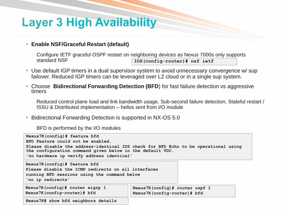
• Enable NSF/Graceful Restart (default)
Configure IETF graceful OSPF restart on neighboring devices as Nexus 7000s only supports standard NSF
• Use default IGP timers in a dual supervisor system to avoid unnecessary convergence w/ sup failover. Reduced IGP timers can be leveraged over L2 cloud or in a single sup system.
• Choose Bidirectional Forwarding Detection (BFD) for fast failure detection vs aggressive timers
Reduced control plane load and link bandwidth usage, Sub-second failure detection, Stateful restart / ISSU & Distributed implementation – hellos sent from I/O module
• Bidirectional Forwarding Detection is supported in NX-OS 5.0
BFD is performed by the I/O modules
Nexus7K(config)# feature bfd
Please disable the ICMP redirects on all interfaces
running BFD sessions using the command below
'no ip redirects'
Nexus7K(config)# feature bfd
BFD Feature could not be enabled.
Please disable the address-identical IDS check for BFD Echo to be operational using the configuration command given below in the default VDC.
'no hardware ip verify address identical'
Nexus7K(config)# router eigrp 1
Nexus7K(config-router)# bfd
Nexus7K(config)# router ospf 1
Nexus7K(config-router)# bfd
Nexus7K# show bfd neighbors details
IOS(config-router)# nsf ietf

General OSPF Best Practices Notes
Enable NSF/Graceful Restart Default (IETF only)
Implement consistent auto-cost reference bandwidth default is 40G
Configure OSPF point-to-point network on point-to-point interfaces
Configure passive-interface on server VLANs
Implement routing protocol authentication
Implement OSPF route summarization
Configure deterministic router-id (loopback0)
Enable routing process on the router-id interface
Utilize OSPF stub/NSSA or totally stub/NSSA area for server VLANs
Configure intra-area transit link between the ABRs
Configure OSPF log adjacency changes Disabled by default
Utilize route-map when redistributing routes default
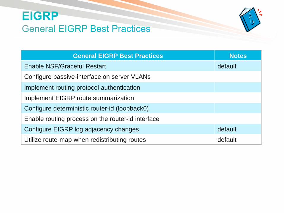
General EIGRP Best Practices Notes
Enable NSF/Graceful Restart default
Configure passive-interface on server VLANs
Implement routing protocol authentication
Implement EIGRP route summarization
Configure deterministic router-id (loopback0)
Enable routing process on the router-id interface
Configure EIGRP log adjacency changes default
Utilize route-map when redistributing routes default
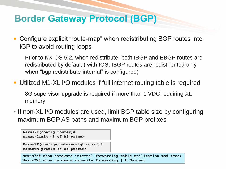
Configure explicit “route-map” when redistributing BGP routes into
IGP to avoid routing loops
Prior to NX-OS 5.2, when redistribute, both IBGP and EBGP routes are
redistributed by default ( with IOS, IBGP routes are redistributed only
when “bgp redistribute-internal” is configured)
Utilized M1-XL I/O modules if full internet routing table is required
8G supervisor upgrade is required if more than 1 VDC requiring XL
memory
• If non-XL I/O modules are used, limit BGP table size by configuring
maximum BGP AS paths and maximum BGP prefixes
Nexus7K(config-router)# maxas-limit <# of AS paths>
Nexus7K(config-router-neighbor-af)#
maximum-prefix <# of prefix>
Nexus7K# show hardware internal forwarding table utilization mod <mod>
Nexus7K# show hardware capacity forwarding | b Unicast

Nexus7K(config)#
feature hsrp
feature interface-vlan
!
vlan <vlan>
!
hsrp timers extended-hold <time>
!
interface vlan <vlan>
description <description>
no shutdown
no ip redirects
ip address <address>/<mask>
hsrp <group>
authentication <text>
preempt delay minimum 180
priority 110
timers 1 3
ip <hsrp address>
Sub-second FHRP timers are not recommended for a dual-sup system
Aggressive timers are not necessary with vPC
Configure HSRP extended hold timers to support NSF during ISSU/Sup switchovers
Not applied with sub-second timers
Configure on all HSRP routers with the same timer (default/minimum is 10s)
Configure HSRP preemption delay
Disable IP proxy ARP to prevent forwarding issues with malfunctioning servers (default)
Configure “no IP redirects” to disable supervisor from generating ICMP redirects
For ECMP, utilize per flow load-balancing (default) to avoid out-of-order packets

• Hardware Overview
• Feature Overview & Best Practices VDCs (Virtual Device Contexts)
Layer-2 Features
vPC (Virtual Port-Channel)
Fabric Path
FEX (Fabric Extender)
Layer-3 Features
OTV (Overlay Transport Virtualization)
Security Features
• Data Center Design Examples
• IOS – NX-OS Configuration Migration

Intra Data Center
L2
L2
L3
OTV
OTV
Inter Data Center
DC1 DC2
Extend Layer 2 between several pods/sites over IP
Simple configuration, does not require full mesh of pseudo-wires
Site independence, STP isolation
No unknown unicast flooding
ARP proxy

• When an Edge Device learns a new MAC address it advertises it together with its associated VLAN IDs and the IP address of the join-interface
• A single OTV update can contain multiple MACs from different VLANs
• With a multicast-enabled transport a single update reaches all neighbors.
MAC Address Advertisements (Multicast-Enabled Transport)
IP A
West
East
3 New MACs are
learned on VLAN 100
Vlan 100 MAC A
Vlan 100 MAC B
Vlan 100 MAC C
South
VLAN MAC IF
100 MAC A IP A
100 MAC B IP A
100 MAC C IP A
4
OTV update is replicated
by the core 3
3
2
VLAN MAC IF
100 MAC A IP A
100 MAC B IP A
100 MAC C IP A
4
3 New MACs are
learned on VLAN 100
1

Transport
Infrastructure
OTV OTV OTV OTV
MAC TABLE
VLAN MAC IF
100 MAC 1 Eth 2
100 MAC 2 Eth 1
100 MAC 3 IP B
100 MAC 4 IP B
MAC 1 MAC 3
IP A IP B MAC 1 MAC 3
MAC TABLE
VLAN MAC IF
100 MAC 1 IP A
100 MAC 2 IP A
100 MAC 3 Eth 3
100 MAC 4 Eth 4
Layer 2
Lookup
5
IP A IP B MAC 1 MAC 3 MAC 1 MAC 3 Layer 2
Lookup
1 Encap
2
Decap
4
MAC 1 MAC 3 West
Site MAC 1
MAC 3 East
Site
3
6
IP A IP B

• Hardware Overview
• Feature Overview & Best Practices VDCs (Virtual Device Contexts)
Layer-2 Features
vPC (Virtual Port-Channel)
Fabric Path
FEX (Fabric Extender)
Layer-3 Features
OTV (Overlay Transport Virtualization)
Security Features
• Data Center Design Examples
• IOS – NX-OS Configuration Migration
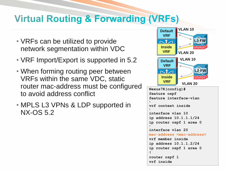
Nexus7K(config)#
feature ospf
feature interface-vlan !
vrf context inside !
interface vlan 10
ip address 10.1.1.1/24
ip router ospf 1 area 0 !
interface vlan 20
mac-address <mac-address>
vrf member inside
ip address 10.1.1.2/24
ip router ospf 1 area 0
!
router ospf 1
vrf inside
• VRFs can be utilized to provide network segmentation within VDC
• VRF Import/Export is supported in 5.2
• When forming routing peer between VRFs within the same VDC, static router mac-address must be configured to avoid address conflict
• MPLS L3 VPNs & LDP supported in NX-OS 5.2
Default
VRF
Inside
VRF
VLAN 10
VLAN 20
L2 FW
Default
VRF
Inside
VRF
VLAN 10
VLAN 20
L3 FW

Nexus7K(config)#
no feature telnet
!
vrf context management
ip route 0.0.0.0/0 <IP address>
!
ip access-list <ACL-name>
10 remark allow specific ssh
11 permit tcp <addr>/24 any eq 22
12 permit tcp any eq 22 <addr>/24
13 deny tcp any any eq 22
14 deny tcp any eq 22 any
20 remark allow specific snmp
21 permit udp <addr>/24 any eq snmp
………..
50 permit ip any any
!
interface mgmt0
ip address <ip address>/<mask>
ip access-group <ACL-name> in
!
line vty
exec-timeout <time>
session-limit <session#>
line console
exec-timeout <time>
!
int cmp-mgmt module <module>
ip address <addr>/<mask>
ip default-gateway <IP addr>
Network Access
• Allow only SSH remote access (default)
If telnet access is required, “feature telnet” needs to be configured
If telnet access to CMP is required, “telnet server enable” need to be configured on the CMP
• Secure interface mgmt0 with ACL
CoPP does not protect interface mgmt0
ACL with the logging option is supported in NX-OS 5.0
• ACL is not supported on VTY
CoPP can be leveraged to secure VTY access
• Configure exec-timeout for VTY and console access Nexus7K-cmp10(config)#
telnet server enable
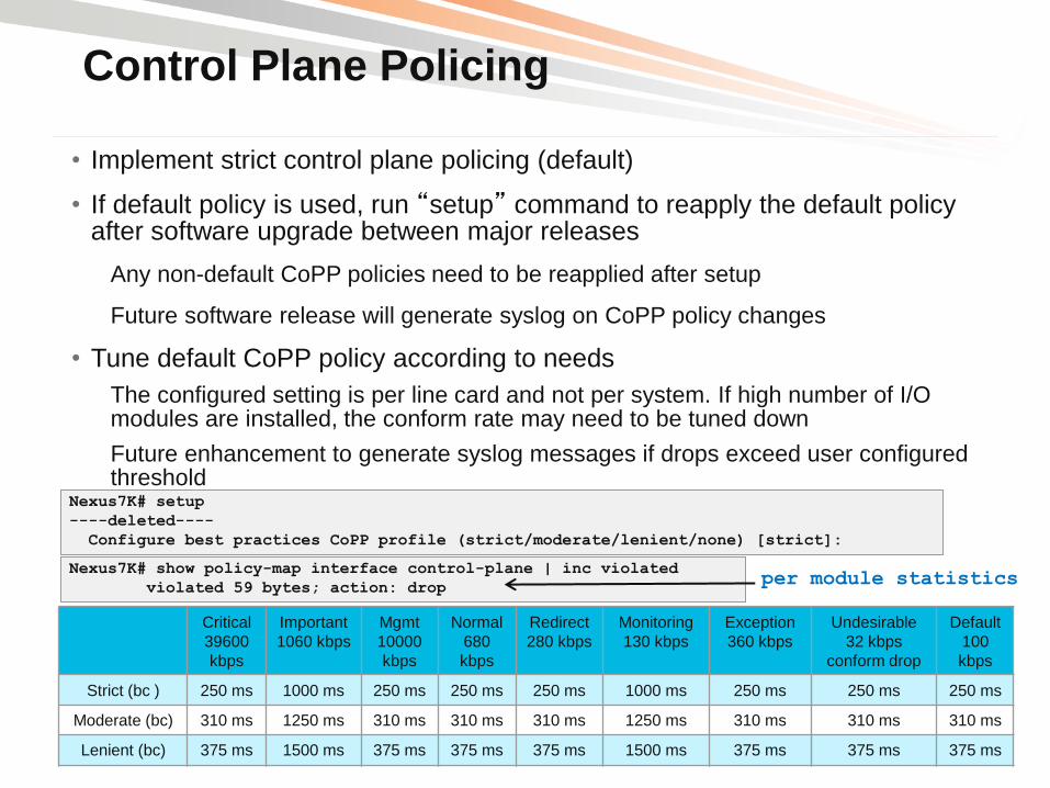
Control Plane Policing
• Implement strict control plane policing (default)
• If default policy is used, run “setup” command to reapply the default policy after software upgrade between major releases
Any non-default CoPP policies need to be reapplied after setup
Future software release will generate syslog on CoPP policy changes
• Tune default CoPP policy according to needs
The configured setting is per line card and not per system. If high number of I/O modules are installed, the conform rate may need to be tuned down
Future enhancement to generate syslog messages if drops exceed user configured threshold
Critical
39600
kbps
Important
1060 kbps
Mgmt
10000
kbps
Normal
680
kbps
Redirect
280 kbps
Monitoring
130 kbps
Exception
360 kbps
Undesirable
32 kbps
conform drop
Default
100
kbps
Strict (bc ) 250 ms 1000 ms 250 ms 250 ms 250 ms 1000 ms 250 ms 250 ms 250 ms
Moderate (bc) 310 ms 1250 ms 310 ms 310 ms 310 ms 1250 ms 310 ms 310 ms 310 ms
Lenient (bc) 375 ms 1500 ms 375 ms 375 ms 375 ms 1500 ms 375 ms 375 ms 375 ms
Nexus7K# show policy-map interface control-plane | inc violated
violated 59 bytes; action: drop
Nexus7K# setup
----deleted----
Configure best practices CoPP profile (strict/moderate/lenient/none) [strict]:
per module statistics
Moderate (bc)
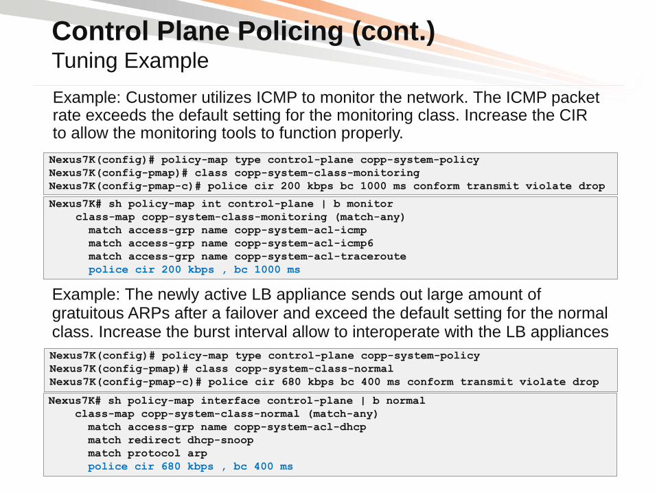
Control Plane Policing (cont.) Tuning Example
Example: Customer utilizes ICMP to monitor the network. The ICMP packet rate exceeds the default setting for the monitoring class. Increase the CIR to allow the monitoring tools to function properly.
Nexus7K(config)# policy-map type control-plane copp-system-policy
Nexus7K(config-pmap)# class copp-system-class-monitoring
Nexus7K(config-pmap-c)# police cir 200 kbps bc 1000 ms conform transmit violate drop
Nexus7K# sh policy-map int control-plane | b monitor
class-map copp-system-class-monitoring (match-any)
match access-grp name copp-system-acl-icmp
match access-grp name copp-system-acl-icmp6
match access-grp name copp-system-acl-traceroute
police cir 200 kbps , bc 1000 ms
Nexus7K(config)# policy-map type control-plane copp-system-policy
Nexus7K(config-pmap)# class copp-system-class-normal
Nexus7K(config-pmap-c)# police cir 680 kbps bc 400 ms conform transmit violate drop
Nexus7K# sh policy-map interface control-plane | b normal
class-map copp-system-class-normal (match-any)
match access-grp name copp-system-acl-dhcp
match redirect dhcp-snoop
match protocol arp
police cir 680 kbps , bc 400 ms
Example: The newly active LB appliance sends out large amount of gratuitous ARPs after a failover and exceed the default setting for the normal class. Increase the burst interval allow to interoperate with the LB appliances

Control Plane Policing (cont.) Tuning Example
This is a sample CoPP configuration to limit SSH access to VTY. Only SSH traffic to and from the management network is allowed to access the Nexus 7000
Nexus7K(config)#
ip access-list copp-system-acl-allow
10 permit tcp <IP network>/24 any eq 22
20 permit tcp any eq 22 <IP network>/24 !
ip access-list copp-system-acl-deny
1 remark ### catch-all for modified mgmt traffic ###
10 permit tcp any any eq 22
20 permit tcp any eq 22 any !
class-map type control-plane match-any copp-system-class-management
no match access-group name copp-system-acl-ssh !
class-map type control-plane match-any copp-system-class-management-allow
match access-group name copp-system-acl-allow
class-map type control-plane match-any copp-system-class-management-deny
match access-group name copp-system-acl-deny !
policy-map type control-plane copp-system-policy
class copp-system-class-management-allow insert-before copp-system-class-normal
police cir 3000 kbps bc 250 ms conform transmit violate drop
class copp-system-class-management-deny insert-before copp-system-class-normal
police cir 3000 kbps bc 250 ms conform drop violate drop

Hardware Rate-Limiter
• Hardware-limiters complement CoPP to protect the CPU (enabled by default)
Rate limit supervisor-bound egress exception and egress redirected traffic
Configure on the default VDC and apply to all VDCs
The configured setting is per line card
• Modify and enable hardware rate-limiters according to needs 4,000
Rate Limiter Class Default
(pps)
Layer-3 MTU 500
Layer-3 TTL 500
Layer-3 control 10,000
Layer-3 glean 100
Layer-3 multicast directly-
connected
3,000
Layer-3 multicast local-
groups
3,000
Layer-3 multicast rpf-leak 500
Layer-2 storm-control Disabled
Access-list-log 100
Copy 30,000
Receive 30,000
Layer-2 port-security Disabled
Layer-2 mcast-snooping 10,000
Layer-2 vpc-low
Nexus7K# sh hardware rate-limiter
Units for Config: packets per second
Allowed, Dropped & Total: aggregated since last clear counters
Rate Limiter Class Parameters
-------------------------------------------------
layer-3 mtu Config : 500
Allowed : 0
Dropped : 0
---deleted---
Nexus7K(config)#
hardware rate-limiter layer-2 <class> <packets/s>

• Hardware Overview
• Feature Overview & Best Practices VDCs (Virtual Device Contexts)
Layer-2 Features
vPC (Virtual Port-Channel)
Fabric Path
FEX (Fabric Extender)
Layer-3 Features
OTV (Overlay Transport Virtualization)
Security Features
• Data Center Design Examples
• IOS – NX-OS Configuration Migration

• Small Data Center with a “virtualized” 3-Tier DC design
• Utilize VDCs on two devices to create a core and aggregation layer
• GE and 10GE ToR access layer switches
• Implement vPC / double-sided vPC for redundant active/active server connections
L2
L3
L3 L2 Channel
L3 link
L2 link
L3 Channel
Core
Aggregation
Access
SW-1b
VDC2 SW-1a
VDC2
active standby
SW-1b
VDC3 SW-1a
VDC3
vPC
L2 active active
vPC Nexus
5000
Nexus
7000
Nexus
7000
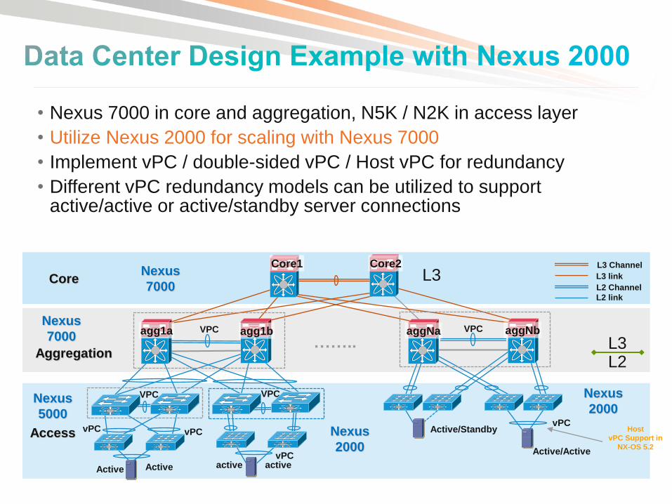
• Nexus 7000 in core and aggregation, N5K / N2K in access layer
• Utilize Nexus 2000 for scaling with Nexus 7000
• Implement vPC / double-sided vPC / Host vPC for redundancy
• Different vPC redundancy models can be utilized to support active/active or active/standby server connections
L2 L3
L3 L2 Channel
L3 link
L2 link
L3 Channel
Access
Core
Aggregation ……..
VPC VPC
VPC VPC
Active Active active active
Active/Standby
Core2 Core1
aggNa aggNb agg1a agg1b
vPC vPC
vPC Active/Active
Nexus
2000
Nexus
2000
Nexus
7000
Nexus
7000
Nexus
5000 vPC
Host
vPC Support in
NX-OS 5.2
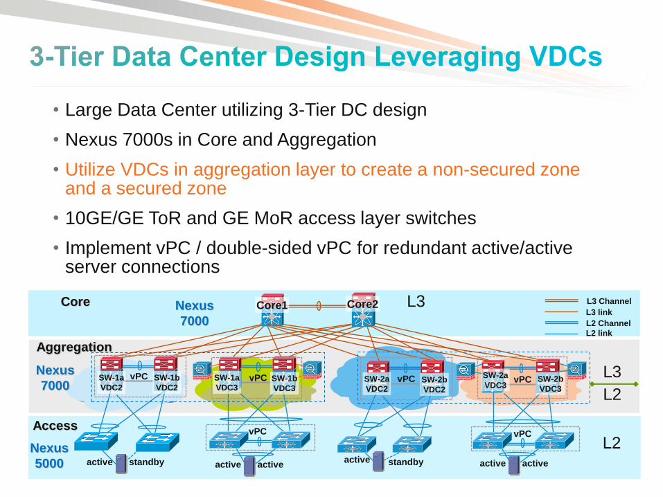
• Large Data Center utilizing 3-Tier DC design
• Nexus 7000s in Core and Aggregation
• Utilize VDCs in aggregation layer to create a non-secured zone and a secured zone
• 10GE/GE ToR and GE MoR access layer switches
• Implement vPC / double-sided vPC for redundant active/active server connections
L2
L3
L3
L2
L2 Channel
L3 link
L2 link
L3 Channel Core
Aggregation
Access
SW-2b
VDC3
SW-2a
VDC3 SW-2a
VDC2 SW-2b
VDC2
SW-1a
VDC3 SW-1b
VDC3
SW-1a
VDC2
SW-1b
VDC2
Core2 Core1
vPC vPC
active active active standby active active active standby
vPC vPC vPC vPC
Nexus
5000
Nexus
7000
Nexus
7000

• Hardware Overview
• Feature Overview & Best Practices VDCs (Virtual Device Contexts)
Layer-2 Features
vPC (Virtual Port-Channel)
Fabric Path
FEX (Fabric Extender)
Layer-3 Features
OTV (Overlay Transport Virtualization)
Security Features
• Data Center Design Examples
• IOS – NX-OS Configuration Migration

Helping Customers migrate from Catalyst to Nexus
Platforms
Automated conversion of IOS configurations to NX-OS
Multiple options for the configuration migration:
Quick converter for one-step conversion
Project based approach for data persistence and reuse
Detailed exception report to highlight the gaps in the migration process
Complimentary Tool access to anyone with a cisco.com user ID
http://tools.cisco.com/nxmt
Supported Platforms*
Source Target
Cat6500 - 12.2 SX Nexus 7000 - 5.1
Cat6500 - 12.2 SX Nexus 5000 - 5.0
Cat4500 - 12.2(54)SG Nexus 7000 - 5.1
Cat4500 - 12.2(54)SG Nexus 7000 - 5.0 *Not all features are supported in Phase 1 release,
more features will be supported in later releases
Email [email protected] for issues & feedback.

We value your feedback !
Please complete Your Session Evaluation

Thank you.