deploying reactive ddos protection using a10 agalaxy system
TRANSCRIPT

DEPLOYMENT GUIDE
DEPLOYING REACTIVE DDOS PROTECTION USING A10 AGALAXY SYSTEM

OVERVIEW Building and operating DDoS defenses is a critical first step for IT administrators in protecting their infrastructure and application from crushing DDoS attacks. Learning the nuances of a new platform requires reading reference manuals and in many cases, hands-on trial and error experience. We have written this deployment guide to give you a simple-to-understand jumpstart in building your defenses.
This deployment guide provides the instructions with screenshots from the A10 Networks aGalaxy® management system to speed up your ability to configure, monitor, and manage the A10 Thunder TPS™ Mitigator and Thunder TPS Detector. The deployment mode shown in this document is flow-based static detection with BGP traffic redirection to an asymmetric reactive mitigation scrubbing platform.
A10 components covered in this deployment guide include:
• aGalaxy management system
• Thunder TPS Mitigator
• Thunder TPS Detector (configured with peacetime baselining using Detection 1.0 setting)
Who is the reader? IT administrators
What is the challenge? The many steps in setting up an A10 Thunder TPS DDoS defense system in a reactive mode
What is the solution? A step-by-step guide for configuring aGalaxy and Thunder TPS
What is the goal? To educate IT administrators on how to set up DDoS defense with aGalaxy
TALK WITH A10CONTACT USa10networks.com/contact
TABLE OF CONTENTS
OVERVIEW ............................................................................................................................................................................ 2
ASYMMETRIC REACTIVE DEPLOYMENT MODE ............................................................................................................... 4
DEPLOYMENT DEPENDENCIES .......................................................................................................................................... 5
NETWORK CONFIGURATION .............................................................................................................................................. 5
NETWORK TOPOLOGY ......................................................................................................................................................... 6
HIGH-LEVEL DEPLOYMENT PROCEDURE ......................................................................................................................... 6
INITIAL DEVICE SETUP ....................................................................................................................................................... 6Thunder TPS Mitigator (Thunder TPS 4435) ........................................................................................................................................................................................6
Thunder TPS Detector (virtual Thunder TPS) ........................................................................................................................................................................................7
Edge Router (Thunder CFW running ACOS 4.1.0-P2) .............................................................................................................................................................................7
Internal Router (Thunder ADC running ACOS 4.1.4-P3) .........................................................................................................................................................................8
Flow Sampling Setting Examples for the Edge Router .........................................................................................................................................................................8
INITIAL AGALAXY SETUP .................................................................................................................................................. 10aGalaxy Network Setting ...........................................................................................................................................................................................................................10
Device Registration.....................................................................................................................................................................................................................................11
Default Operational Policy Update (for reactive asymmetric mode) .................................................................................................................................................13
NEW PROTECTED ZONE USING BUILT-IN PROTECTION PROFILES .............................................................................. 14Creating a New Protected Zone (Reactive203) Using Built-In Protection Profiles ..........................................................................................................................14
Moving This New Protected Zone to Learning Mode ...........................................................................................................................................................................16
Moving This New Protected Zone to Protected Mode .........................................................................................................................................................................17
NEW PROTECTED ZONE USING CUSTOMIZED PROTECTION PROFILES ..................................................................... 19Customizing Protection Profiles for TCP:Other and UDP:Other Services .........................................................................................................................................19
Creating a New Protected Zone (Reactive213) with the Customized Protection Profiles .............................................................................................................21
Moving This New Protected Zone to Learning Mode ...........................................................................................................................................................................23
Moving This New Protected Zone to Protected Mode .........................................................................................................................................................................24
DEPLOYMENT VALIDATION ............................................................................................................................................. 27Validating the Reactive DDoS Protection on reactive203 Zone – Highlighting Automation .........................................................................................................27
Validating the Reactive DDoS Protection on reactive213 Zone – Highlighting ZAP (ZAPR Filtering) .........................................................................................33
SUMMARY .......................................................................................................................................................................... 37
ABOUT A10 NETWORKS.................................................................................................................................................... 37
DISCLAIMER
This document does not create any express or implied warranty about A10 Networks or about its products or services, including but not limited to fitness for a particular use and noninfringement. A10 Networks has made reasonable efforts to verify that the information contained herein is accurate, but A10 Networks assumes no responsibility for its use. All information is provided “as-is.” The product specifications and features described in this publication are based on the latest information available; however, specifications are subject to change without notice, and certain features may not be available upon initial product release. Contact A10 Networks for current information regarding its products or services. A10 Networks’ products and services are subject to A10 Networks’ standard terms and conditions.

4
ASYMMETRIC REACTIVE DEPLOYMENT MODEAt asymmetric reactive deployment, inbound traffic follows the same “native” path as the return traffic during peacetime. When an attack is detected, wartime action is initiated, and the inbound traffic is diverted along the “modified” path while the return traffic still follows the “native” path.
With this deployment mode, a DDoS detection system is required in the network to gain the insight of the inbound traffic from the exported flow data records and alerts the DDoS mitigation system to divert the inbound traffic to itself and apply on-demand mitigation countermeasures. A centralized DDoS security incident and event management system can work in concert with a DDoS detection system and DDoS mitigation system for effective automated DDoS monitoring, detection, alerting, orchestration, protection, and reporting.
Figure 1: Asymmetric reactive deployment with an A10 DDoS protection solution
As shown in Figure1, the asymmetric reactive deployment dictates that the Thunder TPS Detector goes through a learning period to build a peacetime traffic baseline and behavior profiles as per Static Baseline design. When an attack is detected, the Thunder TPS Detector sends a DDoS attack alert to the aGalaxy management system, then the aGalaxy management system instructs the Thunder TPS Mitigator to initiate BPG route redirection (reactive) and applies mitigation countermeasures only on the client-to-server direction of traffic (asymmetric).
This deployment guide provides comprehensive information about the topology and the reactive DDoS protection mode.
Thunder TPS(Mitigator)
Clean Traffic
aGalaxy
BGP
Edge Router Internal Router ServersClients
API, sFlow, SyslogAPI, sFlow, Syslog
Detection Signaling
Return traffic from server
vThunder TPSDetector
Traffic reactivelyrouted through TPS
FlowInformation
V
5
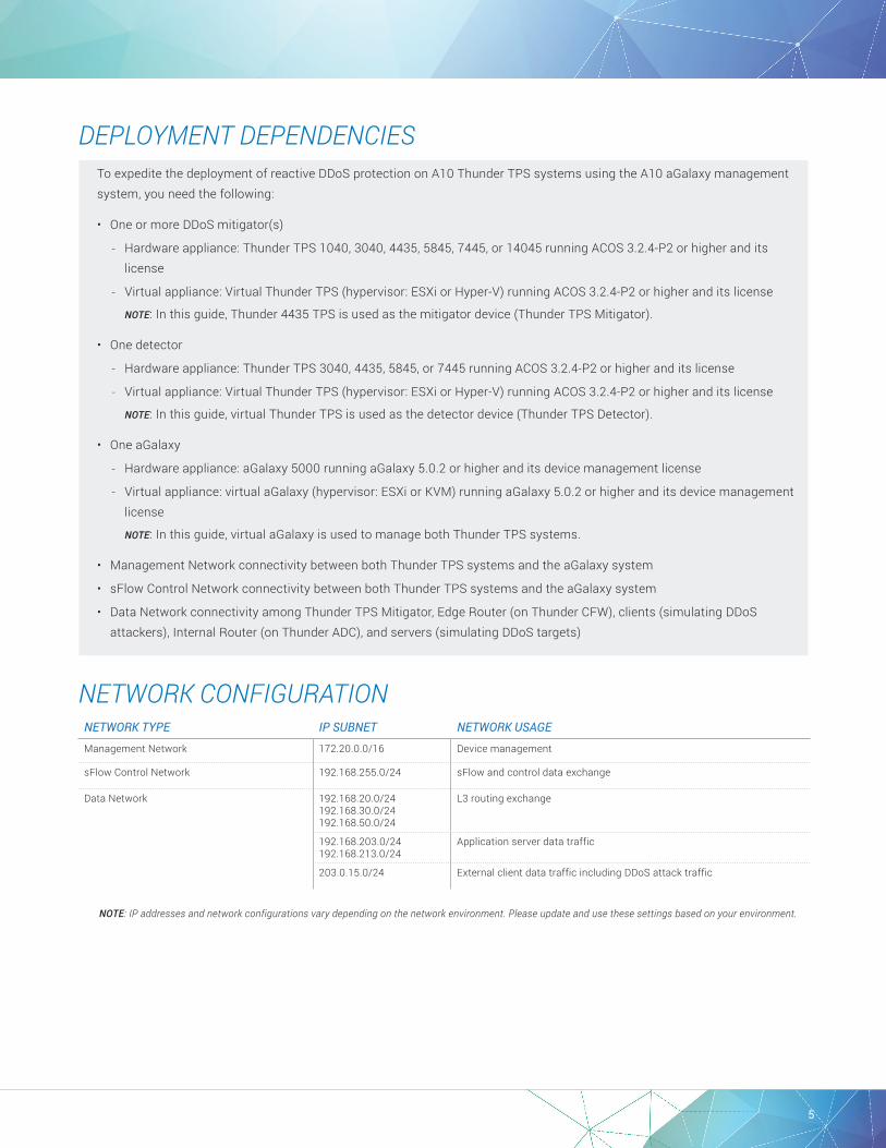
DEPLOYMENT DEPENDENCIESTo expedite the deployment of reactive DDoS protection on A10 Thunder TPS systems using the A10 aGalaxy management system, you need the following:
• One or more DDoS mitigator(s)
- Hardware appliance: Thunder TPS 1040, 3040, 4435, 5845, 7445, or 14045 running ACOS 3.2.4-P2 or higher and its license
- Virtual appliance: Virtual Thunder TPS (hypervisor: ESXi or Hyper-V) running ACOS 3.2.4-P2 or higher and its license
NOTE: In this guide, Thunder 4435 TPS is used as the mitigator device (Thunder TPS Mitigator).
• One detector
- Hardware appliance: Thunder TPS 3040, 4435, 5845, or 7445 running ACOS 3.2.4-P2 or higher and its license
- Virtual appliance: Virtual Thunder TPS (hypervisor: ESXi or Hyper-V) running ACOS 3.2.4-P2 or higher and its license
NOTE: In this guide, virtual Thunder TPS is used as the detector device (Thunder TPS Detector).
• One aGalaxy
- Hardware appliance: aGalaxy 5000 running aGalaxy 5.0.2 or higher and its device management license
- Virtual appliance: virtual aGalaxy (hypervisor: ESXi or KVM) running aGalaxy 5.0.2 or higher and its device management license
NOTE: In this guide, virtual aGalaxy is used to manage both Thunder TPS systems.
• Management Network connectivity between both Thunder TPS systems and the aGalaxy system
• sFlow Control Network connectivity between both Thunder TPS systems and the aGalaxy system
• Data Network connectivity among Thunder TPS Mitigator, Edge Router (on Thunder CFW), clients (simulating DDoS attackers), Internal Router (on Thunder ADC), and servers (simulating DDoS targets)
NETWORK CONFIGURATIONNETWORK TYPE IP SUBNET NETWORK USAGE
Management Network 172.20.0.0/16 Device management
sFlow Control Network 192.168.255.0/24 sFlow and control data exchange
Data Network 192.168.20.0/24192.168.30.0/24192.168.50.0/24
L3 routing exchange
192.168.203.0/24192.168.213.0/24
Application server data traffic
203.0.15.0/24 External client data traffic including DDoS attack traffic
NOTE: IP addresses and network configurations vary depending on the network environment. Please update and use these settings based on your environment.
6
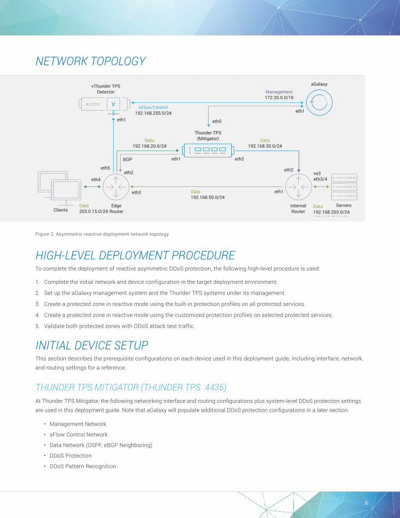
NETWORK TOPOLOGY
Figure 2: Asymmetric reactive deployment network topology
HIGH-LEVEL DEPLOYMENT PROCEDURETo complete the deployment of reactive asymmetric DDoS protection, the following high-level procedure is used:
1. Complete the initial network and device configuration in the target deployment environment.
2. Set up the aGalaxy management system and the Thunder TPS systems under its management.
3. Create a protected zone in reactive mode using the built-in protection profiles on all protected services.
4. Create a protected zone in reactive mode using the customized protection profiles on selected protected services.
5. Validate both protected zones with DDoS attack test traffic.
INITIAL DEVICE SETUPThis section describes the prerequisite configurations on each device used in this deployment guide, including interface, network, and routing settings for a reference.
THUNDER TPS MITIGATOR (THUNDER TPS 4435) At Thunder TPS Mitigator, the following networking interface and routing configurations plus system-level DDoS protection settings are used in this deployment guide. Note that aGalaxy will populate additional DDoS protection configurations in a later section.
• Management Network
• sFlow Control Network
• Data Network (OSPF, eBGP Neighboring)
• DDoS Protection
• DDoS Pattern Recognition
Thunder TPS(Mitigator)
aGalaxy
BGP
EdgeRouter
InternalRouter
ServersClients
sFlow/Control192.168.255.0/24
Data192.168.20.0/24
Data192.168.30.0/24
Data192.168.203.0/24192.168.213.0/24
Data203.0.15.0/24
Data192.168.50.0/24
Management172.20.0.0/16
vThunder TPSDetector
eth5
eth4
eth1
eth1
eth1
eth2
eth2
eth3
eth2ve3eth3/4
eth1
eth5
V

7
interface management ip address 172.20.11.2 255.255.0.0 ip default-gateway 172.20.0.1interface ethernet 1 name to_ExtRT_clients ip address 192.168.20.2 255.255.255.0interface ethernet 2 name to_IntRT_servers ip address 192.168.30.2 255.255.255.0interface ethernet 5 name to_xFlowNW ip address 192.168.255.2 255.255.255.0
router ospf 1 network 192.168.20.0 0.0.0.255 area 0 network 192.168.30.0 0.0.0.255 area 0 router-id 3.3.3.3
router bgp 65000 neighbor 192.168.20.1 remote-as 64512route-map A10-SET-NEXT-HOP permit 1
ddos protection enableddos protection rate-interval 1secddos pattern-recognition dedicated-cpus 2ddos pattern-recognition enable
THUNDER TPS DETECTOR (VIRTUAL THUNDER TPS) At Thunder TPS Detector, the following networking interface configurations plus system-level DDoS protection settings are used. Note that aGalaxy will populate additional DDoS protection and detection configurations in a later section.
• Management Network
• sFlow Control Network
interface management ip address 172.20.11.13 255.255.0.0 ip default-gateway 172.20.0.1
interface ethernet 1 name xFlow_NW ip address 192.168.255.13 255.255.255.0
ddos protection rate-interval 1sec
EDGE ROUTER (THUNDER CFW RUNNING ACOS 4.1.0-P2)At Edge Router, the following networking interface and routing configurations plus sFlow settings, including sampling rate and collector (Thunder TPS Detector listed above), are used in this deployment guide.
• Management Network
• sFlow Control Network
• Data Network (OSPF, eBGP Neighboring)
• sFlow Settings

8
interface management ip address 172.20.14.1 255.255.0.0 ip default-gateway 172.20.0.1 interface ethernet 2 name To_TPS ip address 192.168.20.1 255.255.255.0 interface ethernet 3 name To_Int-Rt ip address 192.168.50.1 255.255.255.0interface ethernet 4 name CLT-NW-15 ip address 203.0.15.254 255.255.255.0interface ethernet 5 name xFlow-NW ip address 192.168.255.1 255.255.255.0
router ospf 1 network 192.168.20.0 0.0.0.255 area 0 network 192.168.50.0 0.0.0.255 area 0 router-id 1.1.1.1 redistribute connected
router bgp 64512 neighbor 192.168.20.2 remote-as 65000 sflow setting packet-sampling-rate 100sflow collector ip 192.168.255.23 6343sflow agent address 172.20.14.1sflow source-address ip 192.168.255.1sflow sampling ethernet 3 to 4
INTERNAL ROUTER (THUNDER ADC RUNNING ACOS 4.1.4-P3)At Internal Router, the following networking interface and routing configurations are used in this deployment guide.
• Management Network
• Data Network (OSPF)
vlan 3 untagged ethernet 3 to 4 router-interface ve 3
interface management ip address 172.20.14.2 255.255.0.0 ip default-gateway 172.20.0.1 interface ethernet 1 name To_Edge-RT ip address 192.168.50.3 255.255.255.0 interface ethernet 2 name To_TPS ip address 192.168.30.3 255.255.255.0
interface ethernet 3interface ethernet 4
interface ve 3 name SRV-NW ip address 192.168.203.3 255.255.255.0 ip address 192.168.213.3 255.255.255.0
router ospf 1 network 192.168.30.0/24 area 0 network 192.168.50.0/24 area 0 router-id 2.2.2.2 redistribute connected
FLOW SAMPLING SETTING EXAMPLES FOR THE EDGE ROUTER As shown at the Edge Router configuration above, sFlow sampling is used in this deployment guide. Note that the Thunder TPS Detector also supports NetFlow sampling as listed below.
• sFlow – default port 6343
• NetFlow v5, v9, NetFlow v10 (IPFIX) – default port 9996
As shown above, the following sFlow settings are applied to the Edge Router.
sflow setting packet-sampling-rate 100sflow collector ip 192.168.255.23 6343sflow agent address 172.20.14.1sflow source-address ip 192.168.255.1sflow sampling ethernet 3 to 4

9
The following NetFlow examples for Cisco routers are included for reference.
• Example 1: Cisco IOS XR Router (e.g., CRS/ASR9000) using NetFlow v9
sampler-map nfs1 random 1 out-of 10000 !flow monitor-map nfm1 record ipv4 exporter nfexp1 !flow exporter-map nfexp1 version v9 transport udp 9996 source Loopback 0 destination 192.168.255.23 # Attaching netflow configuration to an interface: interface GigabitEthernet 0/1/0/0 description External-Peer ipv4 address 203.0.113.20 255.255.255.0 flow ipv4 monitor nfm1 sampler nfs1 ingress flow ipv4 monitor nfm1 sampler nfs1 egress
• Example 2: Cisco IOS Product (e.g., Catalyst 6500/7600) using NetFlow v9
ip flow-export destination 192.168.255.23 9996 ip flow-export source Loopback0 ip flow-export version 9 ip flow-cache timeout active 1 ip flow-cache timeout inactive 15 snmp-server ifindex persist !mls netflow mls nde sender version 9 mls aging long 64 mls aging normal 32 mls sampling packet-based 10000 mls flow ip interface-full mls nde interface # Attaching netflow configuration to an interface: interface GigabitEthernet0/0 description External-Peer ipv4 address 203.0.113.20 255.255.255.0 no switchport ip route-cache flow ip flow ingress mls netflow sampling
10
INITIAL AGALAXY SETUPThis section describes the prerequisite configurations on each device used in this deployment guide, including interface, network, and routing settings for a reference.
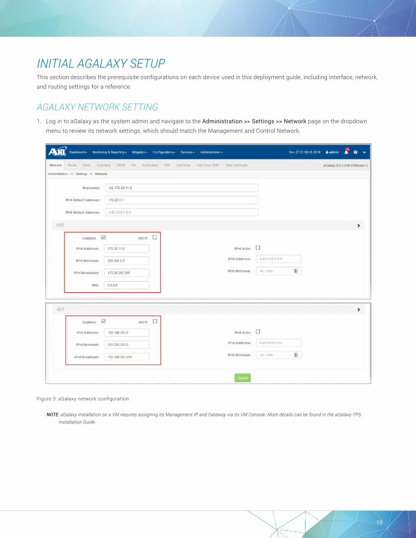
AGALAXY NETWORK SETTING1. Log in to aGalaxy as the system admin and navigate to the Administration >> Settings >> Network page on the dropdown
menu to review its network settings, which should match the Management and Control Network.
Figure 3: aGalaxy network configuration
NOTE: aGalaxy installation on a VM requires assigning its Management IP and Gateway via its VM Console. More details can be found in the aGalaxy-TPS Installation Guide.

11
2. Navigate to the Devices >> Device Settings >> sFlow page on the dropdown menu to review its sFlow settings, which should use its IP address on Control Network with other Thunder TPS systems.
Figure 4: aGalaxy sFlow setting
DEVICE REGISTRATION1. Navigate to the Devices >> Device List page on the dropdown menu, and click the + Add Devices button to both Thunder 4435
TPS (Mitigator) and virtual Thunder TPS (Detector) to be under aGalaxy-TPS management.
Figure 5: Adding devices
12
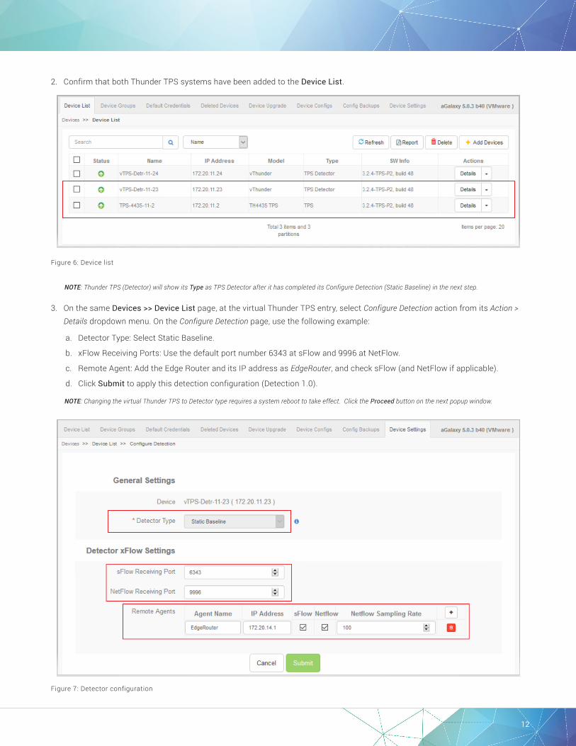
2. Confirm that both Thunder TPS systems have been added to the Device List.
Figure 6: Device list
NOTE: Thunder TPS (Detector) will show its Type as TPS Detector after it has completed its Configure Detection (Static Baseline) in the next step.
3. On the same Devices >> Device List page, at the virtual Thunder TPS entry, select Configure Detection action from its Action > Details dropdown menu. On the Configure Detection page, use the following example:
a. Detector Type: Select Static Baseline.
b. xFlow Receiving Ports: Use the default port number 6343 at sFlow and 9996 at NetFlow.
c. Remote Agent: Add the Edge Router and its IP address as EdgeRouter, and check sFlow (and NetFlow if applicable).
d. Click Submit to apply this detection configuration (Detection 1.0).
NOTE: Changing the virtual Thunder TPS to Detector type requires a system reboot to take effect. Click the Proceed button on the next popup window.
Figure 7: Detector configuration
13
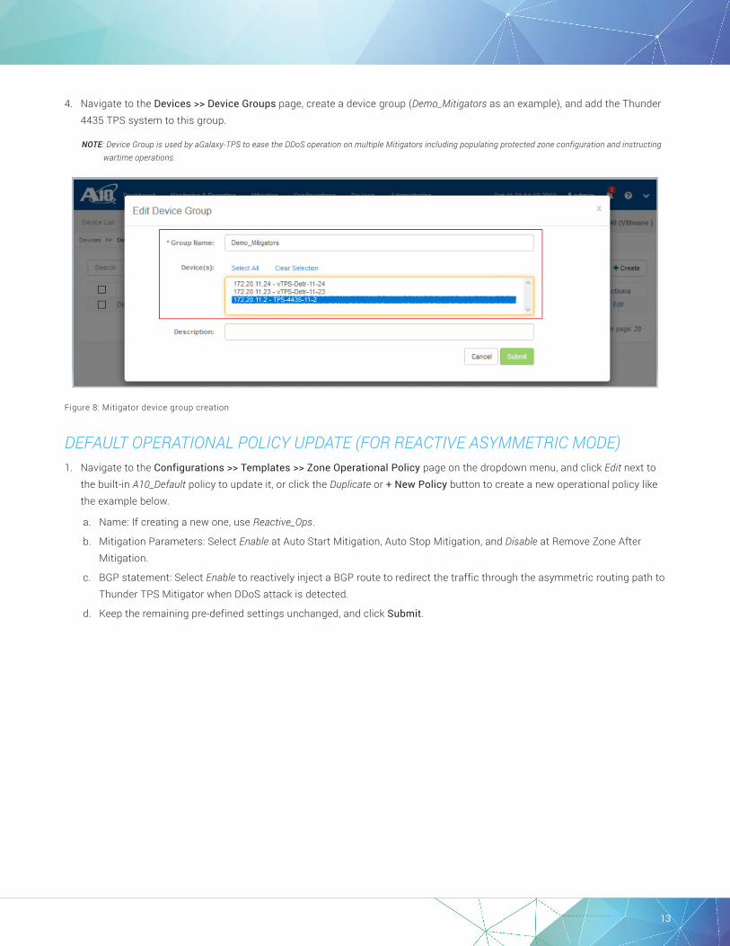
4. Navigate to the Devices >> Device Groups page, create a device group (Demo_Mitigators as an example), and add the Thunder 4435 TPS system to this group.
NOTE: Device Group is used by aGalaxy-TPS to ease the DDoS operation on multiple Mitigators including populating protected zone configuration and instructing wartime operations.
Figure 8: Mitigator device group creation
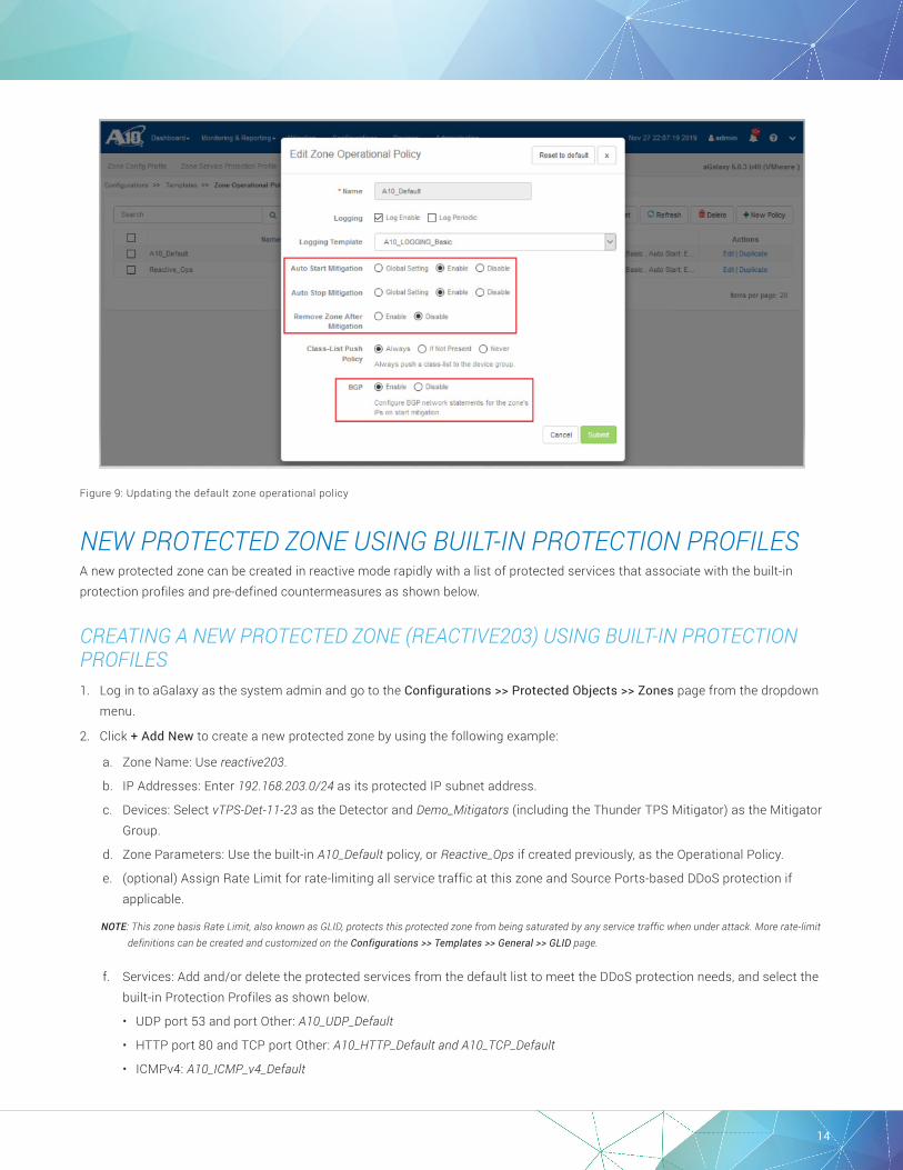
DEFAULT OPERATIONAL POLICY UPDATE (FOR REACTIVE ASYMMETRIC MODE)1. Navigate to the Configurations >> Templates >> Zone Operational Policy page on the dropdown menu, and click Edit next to
the built-in A10_Default policy to update it, or click the Duplicate or + New Policy button to create a new operational policy like the example below.
a. Name: If creating a new one, use Reactive_Ops.
b. Mitigation Parameters: Select Enable at Auto Start Mitigation, Auto Stop Mitigation, and Disable at Remove Zone After Mitigation.
c. BGP statement: Select Enable to reactively inject a BGP route to redirect the traffic through the asymmetric routing path to Thunder TPS Mitigator when DDoS attack is detected.
d. Keep the remaining pre-defined settings unchanged, and click Submit.
14
Figure 9: Updating the default zone operational policy
NEW PROTECTED ZONE USING BUILT-IN PROTECTION PROFILESA new protected zone can be created in reactive mode rapidly with a list of protected services that associate with the built-in protection profiles and pre-defined countermeasures as shown below.
CREATING A NEW PROTECTED ZONE (REACTIVE203) USING BUILT-IN PROTECTION PROFILES1. Log in to aGalaxy as the system admin and go to the Configurations >> Protected Objects >> Zones page from the dropdown
menu.
2. Click + Add New to create a new protected zone by using the following example:
a. Zone Name: Use reactive203.
b. IP Addresses: Enter 192.168.203.0/24 as its protected IP subnet address.
c. Devices: Select vTPS-Det-11-23 as the Detector and Demo_Mitigators (including the Thunder TPS Mitigator) as the Mitigator Group.
d. Zone Parameters: Use the built-in A10_Default policy, or Reactive_Ops if created previously, as the Operational Policy.
e. (optional) Assign Rate Limit for rate-limiting all service traffic at this zone and Source Ports-based DDoS protection if applicable.
NOTE: This zone basis Rate Limit, also known as GLID, protects this protected zone from being saturated by any service traffic when under attack. More rate-limit definitions can be created and customized on the Configurations >> Templates >> General >> GLID page.
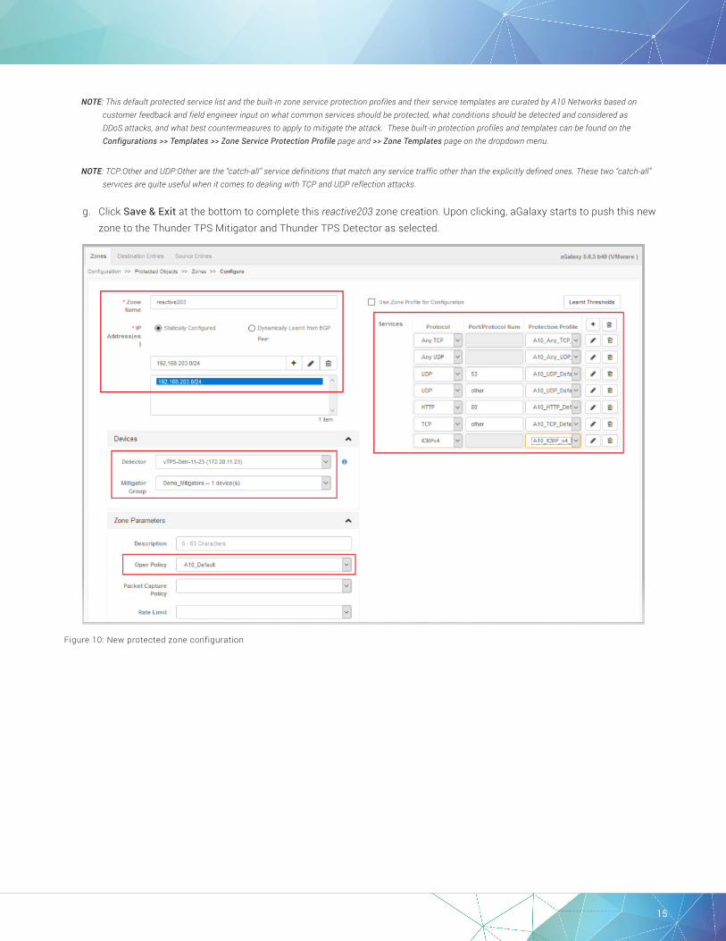
f. Services: Add and/or delete the protected services from the default list to meet the DDoS protection needs, and select the built-in Protection Profiles as shown below.
• UDP port 53 and port Other: A10_UDP_Default
• HTTP port 80 and TCP port Other: A10_HTTP_Default and A10_TCP_Default
• ICMPv4: A10_ICMP_v4_Default
15
NOTE: This default protected service list and the built-in zone service protection profiles and their service templates are curated by A10 Networks based on customer feedback and field engineer input on what common services should be protected, what conditions should be detected and considered as DDoS attacks, and what best countermeasures to apply to mitigate the attack. These built-in protection profiles and templates can be found on the Configurations >> Templates >> Zone Service Protection Profile page and >> Zone Templates page on the dropdown menu.
NOTE: TCP:Other and UDP:Other are the “catch-all” service definitions that match any service traffic other than the explicitly defined ones. These two “catch-all” services are quite useful when it comes to dealing with TCP and UDP reflection attacks.
g. Click Save & Exit at the bottom to complete this reactive203 zone creation. Upon clicking, aGalaxy starts to push this new zone to the Thunder TPS Mitigator and Thunder TPS Detector as selected.
Figure 10: New protected zone configuration

16
MOVING THIS NEW PROTECTED ZONE TO LEARNING MODE1. Change the Oper. Mode (Operational Mode) of this new protected zone to Learn to allow the Thunder TPS Detector to learn the
traffic thresholds of each protected service port and build a precise traffic profile in peacetime.
Figure 11: Moving this new zone to learning mode
2. Upon clicking Learn, a Configure Zone Learning window pops up. Select 7 days at the Learning Duration as the best practice recommended by A10 Networks, or select Until Stopped (Default). Use pre-defined values on remaining fields, and click Start Learning to allow the Thunder TPS Detector to learn the traffic thresholds of each protected service port in this new protected zone.
NOTE: Upon clicking Start Learning, a traffic threshold page shows up with dynamic threshold updates on the Thunder TPS Detector. Click Exit to allow the detector to complete its learning.
Figure 12: Zone learning configuration

17
MOVING THIS NEW PROTECTED ZONE TO PROTECTED MODE1. After the learning period, change the Oper. Mode (Operational Mode) of this protected zone to Protect to activate DDoS
protection.
Figure 13: Moving this new zone to protected mode
2. Upon clicking Protect, the traffic thresholds of each protected service port in this Protected Zone are displayed. Click each service to examine its traffic thresholds learned by the Thunder TPS Detector. Activate DDoS protection using these learned thresholds for detection and mitigation as shown below.
a. Threshold Source: Select Use learnt service threshold values.
b. Detection Sensitivity: Select Medium (Default).
c. Click Start Protection to activate DDoS protection at this new protected zone.
NOTE: Upon clicking Start Protection, these learned thresholds will be populated to the Thunder TPS Detector to monitor for traffic anomalies and to the Thunder TPS Mitigator to activate mitigation countermeasures.
Figure 14: Traffic indicator and threshold source setting
18
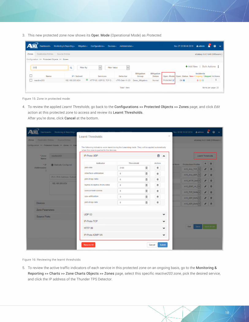
3. This new protected zone now shows its Oper. Mode (Operational Mode) as Protected.
Figure 15: Zone in protected mode
4. To review the applied Learnt Thresholds, go back to the Configurations >> Protected Objects >> Zones page, and click Edit action at this protected zone to access and review its Learnt Thresholds. After you’re done, click Cancel at the bottom.
Figure 16: Reviewing the learnt thresholds
5. To review the active traffic indicators of each service in this protected zone on an ongoing basis, go to the Monitoring & Reporting >> Charts >> Zone Charts Objects >> Zones page, select this specific reactive203 zone, pick the desired service, and click the IP address of the Thunder TPS Detector.

19
Figure 17: Active traffic indicators shown on zone charts
These steps demonstrate a simple way to expedite the creation of one new protected zone by using the built-in default zone service protection profiles and activate its DDoS protection with Static Baseline.
NEW PROTECTED ZONE USING CUSTOMIZED PROTECTION PROFILESIn the protected zone above, its TCP:Other and UDP:Other service ports could also use customized protection profiles to take advantage of the newly introduced zero-day automated protection, known as ZAP, against first-of-the-kind, volumetric DDoS attacks besides TCP and UDP reflection attacks. The following steps demonstrate the creation of the customized protection profiles with ZAP enabled and the use of it in the creation of a new protected zone in reactive mode. In a later section, a validation test will be conducted to examine ZAP functionality and its work toward DDoS attack mitigation along with other countermeasures.
NOTE: ZAP-ZAPR Filtering is the newly introduced signature-based mitigation countermeasure against volumetric DDoS attacks. ZAPR filtering stands for Zero-day Attack Pattern Recognition filtering, which is powered by machine learning. It can help increase mitigation accuracy against the volumetric attacks by inspecting and learning attack traffic patterns and automatically creating BPF filters to match and drop the volumetric attacks. ZAPR filtering is applicable to TCP, UDP, and DNS services ports, and its configuration is pushed by aGalaxy to Thunder TPS Mitigator upon receiving a DDoS attack and level escalation alert.
CUSTOMIZING PROTECTION PROFILES FOR TCP:OTHER AND UDP:OTHER SERVICES1. Log in to aGalaxy as the system admin and go to the Configurations >> Protected Objects >> Zone Service Protection Profile
page from the dropdown menu.
2. Click Duplicate next to A10_TCP_Default or + New TCP Zone Service Profile to customize a new profile for TCP service by using the following example:
a. Name: Use reactive213_TCP.
b. Rate Limit: Select A10-3Kpps and Drop as its service-level rate limit action.
NOTE: This rate limit is the service-level rate limit that protects this TCP service from failing when under attack. This rate limit selection, A10-3Kpps, is the packet-rate basis for allowing up to 3,000 packets per rate interval (one second) at the Thunder TPS Mitigator. It is an essential threshold to gauge the severity of the volumetric DDoS packets and to trigger ZAP-ZAPR filtering along with the Drop action. More rate limit definitions can be found, revised, and created on the Configurations >> Templates >> General >> GLID page on the dropdown menu.

20
NOTE: The current rate limit selection, A10-3Kpps, can be updated with a rate limit closer to the actual traffic threshold after the target protected zone has gone through its learning mode and has been moved into protected mode.
c. Pattern Recognition: Use Level 1 at Start Pattern Recognition and Apply Extracted Filters to enable ZAP-ZAPR Filtering.
NOTE: In order to allow the Thunder TPS Mitigator to capture excessive DDoS attack packets for ZAP-ZAPR Filtering (starting pattern recognition), a packet-rate basis rate limit is required along with Drop action.
d. Use pre-defined level escalation configurations at Level 0 and Level 1 in case you duplicate from the A10_TCP_Default profile; otherwise, add Level 0 and Level 1 to this new profile, use 10 as the Zone Escalation Score at Level 0, add a pkt-rate indicator with 20 as its Score and 2000 as its Threshold Per Zone, and use A10_TCP_Intermediate as the TCP Template at Level 1.
NOTE: This built-in A10_TCP_Intermediate template contains the best practices for protecting TCP service with SYN Authentication, SYN Cookie, ACK Authentication, and Connection rate limit etc. countermeasures. More zone templates can be found on the Configurations >> Templates >> Zone Templates page on the dropdown menu.
e. Click Submit to complete this TCP protection profile creation.
Figure 18: TCP service protection profile creation
Figure 19: TCP service protection profile creation—Level 0
21
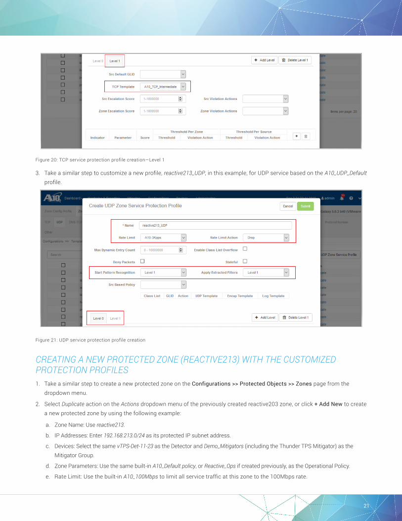
Figure 20: TCP service protection profile creation—Level 1
3. Take a similar step to customize a new profile, reactive213_UDP, in this example, for UDP service based on the A10_UDP_Default profile.
Figure 21: UDP service protection profile creation
CREATING A NEW PROTECTED ZONE (REACTIVE213) WITH THE CUSTOMIZED PROTECTION PROFILES1. Take a similar step to create a new protected zone on the Configurations >> Protected Objects >> Zones page from the
dropdown menu.
2. Select Duplicate action on the Actions dropdown menu of the previously created reactive203 zone, or click + Add New to create a new protected zone by using the following example:
a. Zone Name: Use reactive213.
b. IP Addresses: Enter 192.168.213.0/24 as its protected IP subnet address.
c. Devices: Select the same vTPS-Det-11-23 as the Detector and Demo_Mitigators (including the Thunder TPS Mitigator) as the Mitigator Group.
d. Zone Parameters: Use the same built-in A10_Default policy, or Reactive_Ops if created previously, as the Operational Policy.
e. Rate Limit: Use the built-in A10_100Mbps to limit all service traffic at this zone to the 100Mbps rate.

22
f. Services: Add and/or delete the protected services to meet the DDoS protection needs, select the built-in Protection Profiles for common service ports, and use the customized profiles for TCP:Other and UDP:Other as shown below.
• HTTP port 80: A10_HTTP_Default.
• ICMPv4: A10_ICMP_v4_Default.
• TCP port Other: reactive213_TCP.
• UDP port 53: A10_UDP_Default.
• UDP port Other: reactive213_UDP.
g. Click Save & Exit at the bottom to complete this reactive213 zone creation. Upon clicking, aGalaxy starts to push this new zone to the Thunder TPS Mitigator and Thunder TPS Detector as selected.
NOTE: In case of duplicating from the existing reactive203 zone, its Oper. Mode will be duplicated to this new zone. Use the next two steps to move this new zone through its Learning mode then Protected mode to establish its own traffic baseline.
Figure 22: New protected zone configuration

23
MOVING THIS NEW PROTECTED ZONE TO LEARNING MODE1. Change the Oper. Mode of this new protected zone to Learn to allow the Thunder TPS Detector to learn the traffic thresholds
of each protected service port, and build a precise traffic profile in peacetime.
NOTE: As shown below, this new reactive213 zone is duplicated from the existing reactive203 zone and its Oper. Mode is also duplicated.
Figure 23: Moving this new zone to learning mode
2. Upon clicking Learn, a Configure Zone Learning window pops up. Select 7 days at the Learning Duration as the best practice recommended by A10 Networks, or select Until Stopped (Default). Use pre-defined values on remaining fields, and click Start Learning to allow the Thunder TPS Detector to learn the traffic thresholds of each protected service port in this new protected zone.
NOTE: Upon clicking Restart Learning, a traffic threshold page shows up with dynamic threshold updates on the Thunder TPS Detector. Click Exit to allow the detector to complete its learning.
Figure 24: Zone learning configuration

24
MOVING THIS NEW PROTECTED ZONE TO PROTECTED MODE1. After the learning period, change the Oper. Mode (Operational Mode) of this protected zone to Protect to activate DDoS protection.
Figure 25: Moving this new zone to protected mode
2. Upon clicking Protect, the traffic thresholds of each protected service port in this Protected Zone is displayed. Click each service to examine its traffic thresholds learned by the Thunder TPS Detector. Activate DDoS protection using these learned thresholds for detection and mitigation as shown below.
a. Threshold Source: Select Use learnt service threshold values.
b. Detection Sensitivity: Select Medium (Default).
c. Click Start Protection to activate DDoS protection at this new protected zone.
Figure 26: Traffic indicator and threshold source setting
25
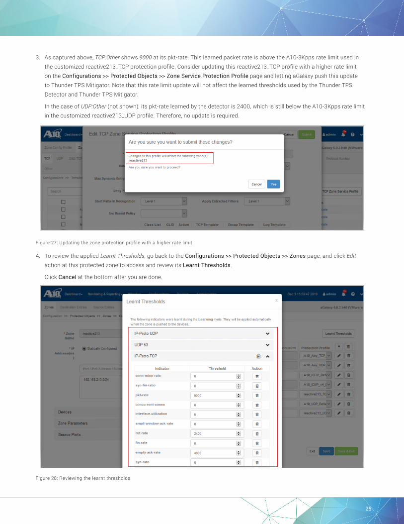
3. As captured above, TCP:Other shows 9000 at its pkt-rate. This learned packet rate is above the A10-3Kpps rate limit used in the customized reactive213_TCP protection profile. Consider updating this reactive213_TCP profile with a higher rate limit on the Configurations >> Protected Objects >> Zone Service Protection Profile page and letting aGalaxy push this update to Thunder TPS Mitigator. Note that this rate limit update will not affect the learned thresholds used by the Thunder TPS Detector and Thunder TPS Mitigator.
In the case of UDP:Other (not shown), its pkt-rate learned by the detector is 2400, which is still below the A10-3Kpps rate limit in the customized reactive213_UDP profile. Therefore, no update is required.
Figure 27: Updating the zone protection profile with a higher rate limit
4. To review the applied Learnt Thresholds, go back to the Configurations >> Protected Objects >> Zones page, and click Edit action at this protected zone to access and review its Learnt Thresholds.
Click Cancel at the bottom after you are done.
Figure 28: Reviewing the learnt thresholds
26
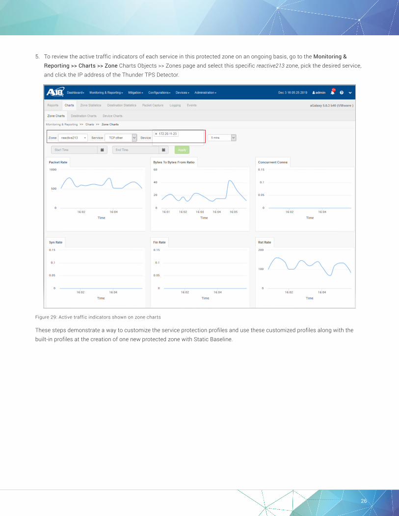
5. To review the active traffic indicators of each service in this protected zone on an ongoing basis, go to the Monitoring & Reporting >> Charts >> Zone Charts Objects >> Zones page and select this specific reactive213 zone, pick the desired service, and click the IP address of the Thunder TPS Detector.
Figure 29: Active traffic indicators shown on zone charts
These steps demonstrate a way to customize the service protection profiles and use these customized profiles along with the built-in profiles at the creation of one new protected zone with Static Baseline.
27
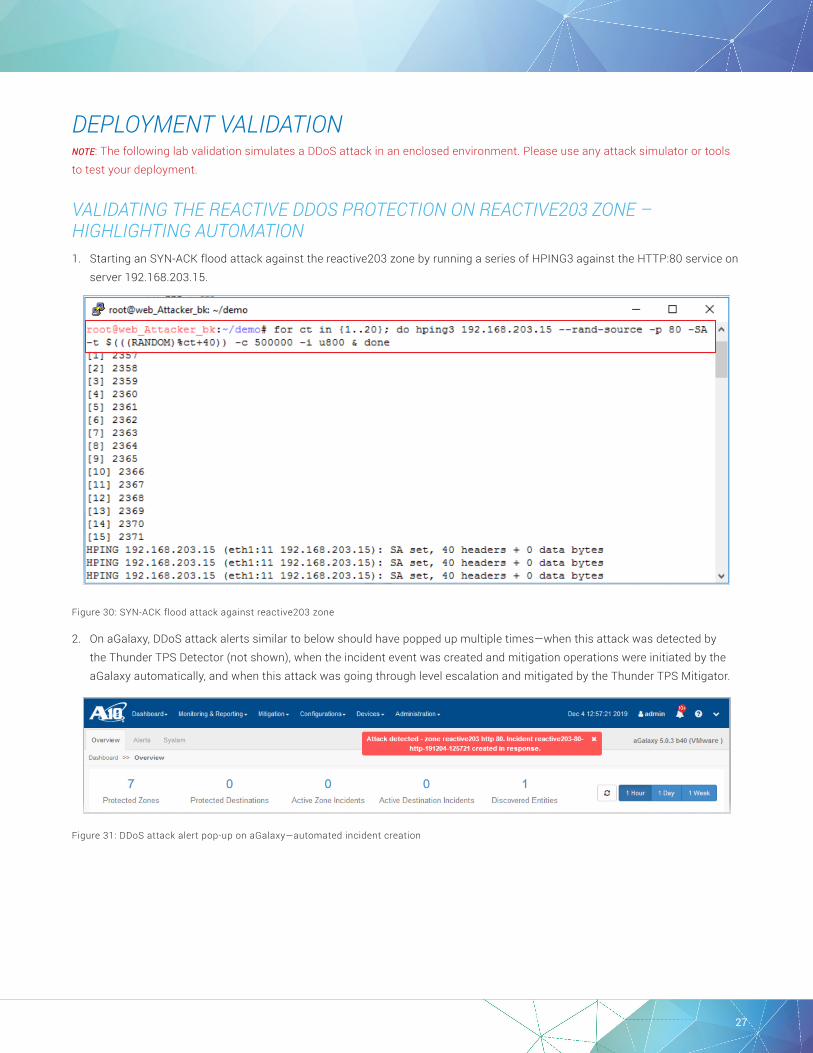
DEPLOYMENT VALIDATION NOTE: The following lab validation simulates a DDoS attack in an enclosed environment. Please use any attack simulator or tools to test your deployment.
VALIDATING THE REACTIVE DDOS PROTECTION ON REACTIVE203 ZONE – HIGHLIGHTING AUTOMATION1. Starting an SYN-ACK flood attack against the reactive203 zone by running a series of HPING3 against the HTTP:80 service on
server 192.168.203.15.
Figure 30: SYN-ACK flood attack against reactive203 zone
2. On aGalaxy, DDoS attack alerts similar to below should have popped up multiple times—when this attack was detected by the Thunder TPS Detector (not shown), when the incident event was created and mitigation operations were initiated by the aGalaxy automatically, and when this attack was going through level escalation and mitigated by the Thunder TPS Mitigator.
Figure 31: DDoS attack alert pop-up on aGalaxy—automated incident creation

28
Figure 32: DDoS attack alert pop-up on aGalaxy—level escalation on the mitigator
3. Click Active Zone Incidents on the Dashboard or go to the Mitigation >> Zone Incidents page on the dropdown menu. Confirm that aGalaxy shows an overview of this ongoing attack with its Incident Name made up by the names of the zone, the service under attack, and the timestamp of the attack. Note that, as shown in Attack Type, previously undetected POST Flood, Malformed attack, and SlowLoris attacks have been caught by this mitigation.
Figure 33: DDoS Zone Incident overview—ongoing attack

29
4. Click Mitigation Console on the Actions dropdown menu of this incident or go to the Mitigation >> Zone Mitigation Console page on the dropdown menu. Confirm that the reactive203 zone and its HTTP:80 is under attack and that this attack has been mitigated as shown in the traffic chart. The countermeasure used in this mitigation is TCP Authentication as defined in the A10_TCP_Intermediate template of the built-in A10_HTTP_Default service profile.
Figure 34: DDoS Mitigation Console
30
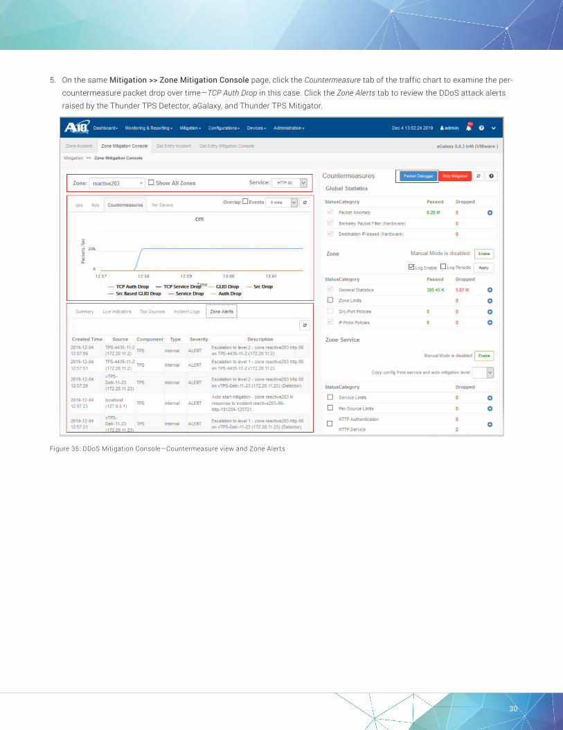
5. On the same Mitigation >> Zone Mitigation Console page, click the Countermeasure tab of the traffic chart to examine the per-countermeasure packet drop over time—TCP Auth Drop in this case. Click the Zone Alerts tab to review the DDoS attack alerts raised by the Thunder TPS Detector, aGalaxy, and Thunder TPS Mitigator.
Figure 35: DDoS Mitigation Console—Countermeasure view and Zone Alerts

31
6. As shown on the upper right corner of the Mitigation Console, the Packet Debugger can be used to capture the live traffic passing through this reactive203 zone (forward) from the Thunder TPS Mitigator for closer examination or debugging purposes.
Figure 36: Packet Debugger view
7. Once the DDoS attack is stopped, aGalaxy shows the status of this corresponding incident as Stopped, and an incident report is automatically generated and accessible on the same Zone Incident view.
Figure 37: DDoS Zone Incident overview—Stopped attack and shortcut to incident report
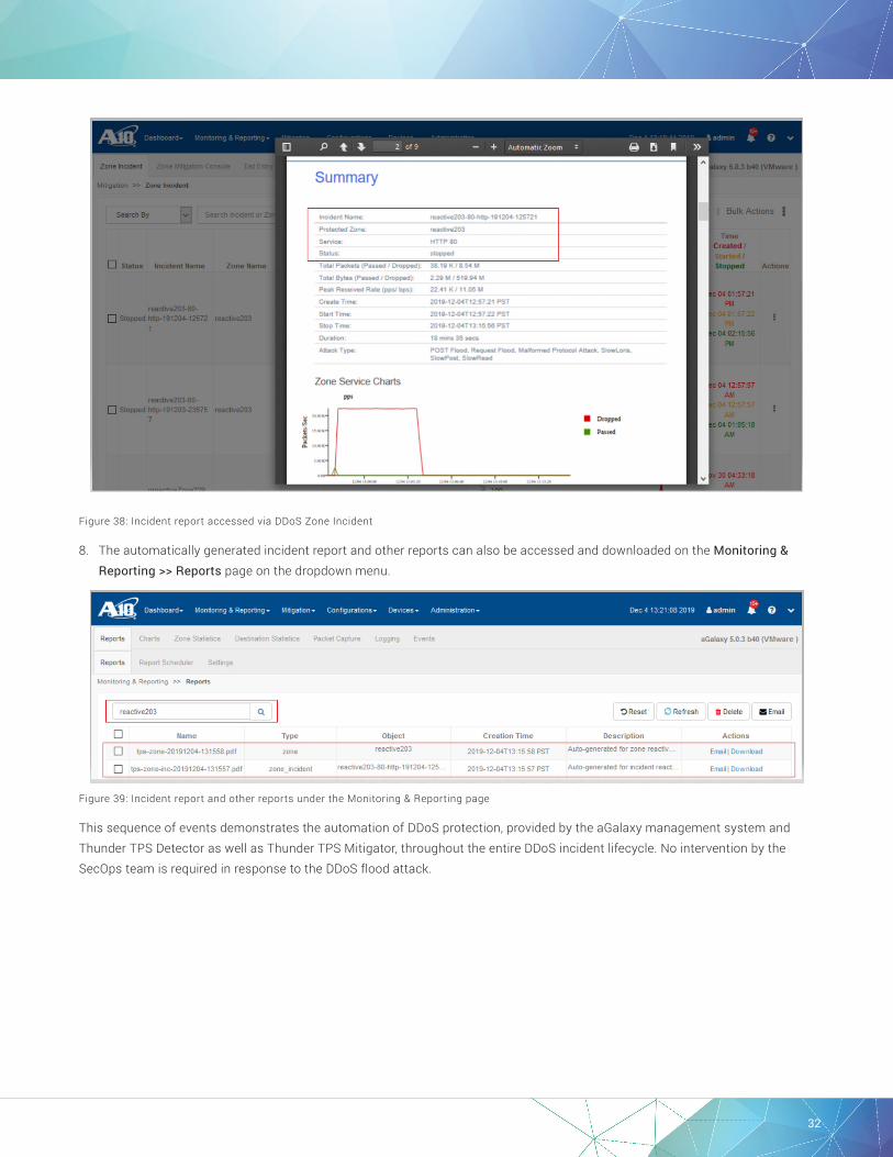
32
Figure 38: Incident report accessed via DDoS Zone Incident
8. The automatically generated incident report and other reports can also be accessed and downloaded on the Monitoring & Reporting >> Reports page on the dropdown menu.
Figure 39: Incident report and other reports under the Monitoring & Reporting page
This sequence of events demonstrates the automation of DDoS protection, provided by the aGalaxy management system and Thunder TPS Detector as well as Thunder TPS Mitigator, throughout the entire DDoS incident lifecycle. No intervention by the SecOps team is required in response to the DDoS flood attack.

33
VALIDATING THE REACTIVE DDOS PROTECTION ON REACTIVE213 ZONE – HIGHLIGHTING ZAP (ZAPR FILTERING)1. Starting UDP flood attack against the reactive213 zone by replaying a captured live traffic from a script against the UDP:Other
service on server 192.168.213.18.
Figure 40: UDP flood attack against reactive213 zone
2. On aGalaxy, DDoS attack alerts similar to the one below should have popped up multiple times—when this attack was detected by the Thunder TPS Detector, when the incident event was created and mitigation operations were initiated by the aGalaxy automatically, and when this attack was going through level escalation and mitigated by the Thunder TPS Mitigator (not shown).
Figure 41: DDoS attack alert pop-up on aGalaxy—the attack is detected by the detector
Figure 42: DDoS attack alert pop-up on aGalaxy—automated incident creation
34
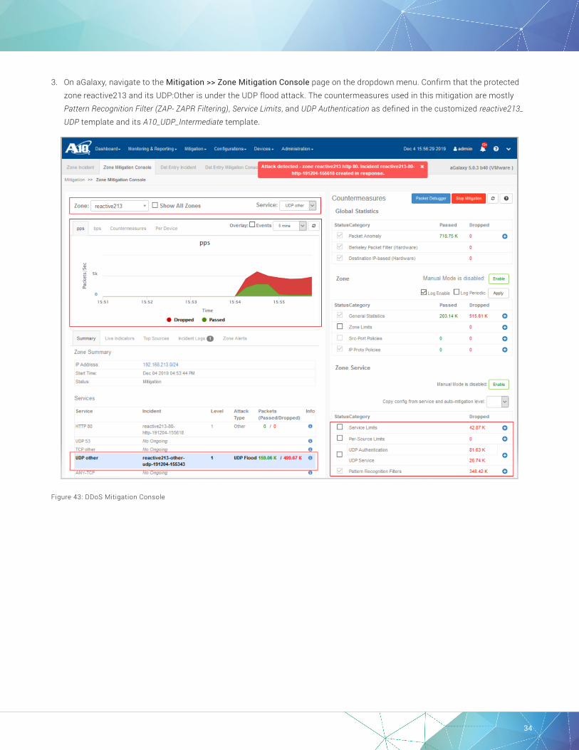
3. On aGalaxy, navigate to the Mitigation >> Zone Mitigation Console page on the dropdown menu. Confirm that the protected zone reactive213 and its UDP:Other is under the UDP flood attack. The countermeasures used in this mitigation are mostly Pattern Recognition Filter (ZAP- ZAPR Filtering), Service Limits, and UDP Authentication as defined in the customized reactive213_UDP template and its A10_UDP_Intermediate template.
Figure 43: DDoS Mitigation Console

35
4. On the same Mitigation >> Zone Mitigation Console page, click the Countermeasure tab of the ongoing attack traffic chart to examine the per-countermeasure packet drop over time. ZAPR Filter Drop plays a primary mitigation role in this case.
Figure 44: DDoS Mitigation Console—Countermeasure view
5. On the same Mitigation Console view, click the Incident Logs tab to review the related log messages captured by aGalaxy.
Figure 45: DDoS Mitigation Console—Incident Logs and More button for ZAP-ZAPR Filtering detail
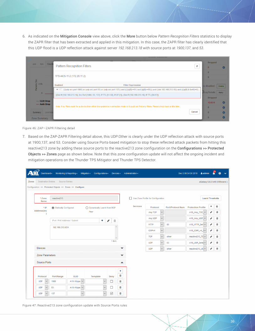
36
6. As indicated on the Mitigation Console view above, click the More button below Pattern Recognition Filters statistics to display the ZAPR filter that has been extracted and applied in this mitigation. In this case, the ZAPR filter has clearly identified that this UDP flood is a UDP reflection attack against server 192.168.213.18 with source ports at 1900,137, and 53.
Figure 46: ZAP—ZAPR Filtering detail
7. Based on the ZAP-ZAPR Filtering detail above, this UDP:Other is clearly under the UDP reflection attack with source ports at 1900,137, and 53. Consider using Source Ports-based mitigation to stop these reflected attack packets from hitting this reactive213 zone by adding these source ports to the reactive213 zone configuration on the Configurations >> Protected Objects >> Zones page as shown below. Note that this zone configuration update will not affect the ongoing incident and mitigation operations on the Thunder TPS Mitigator and Thunder TPS Detector.
Figure 47: Reactive213 zone configuration update with Source Ports rules
37
©2019 A10 Networks, Inc. All rights reserved. A10 Networks, the A10 Networks logo, ACOS, A10 Thunder, A10 Lightning, A10 Harmony and SSL Insight are trademarks or registered trademarks of A10 Networks, Inc. in the United States and other countries. All other trademarks are property of their respective owners. A10 Networks assumes no responsibility for any inaccuracies in this document. A10 Networks reserves the right to change, modify, transfer, or otherwise revise this publication without notice. For the full list of trademarks, visit: www.a10networks.com/a10-trademarks.
LEARN MORE ABOUT A10 NETWORKS
CONTACT USa10networks.com/contact Part Number: A10-DG-16173-EN-01 DEC 2019
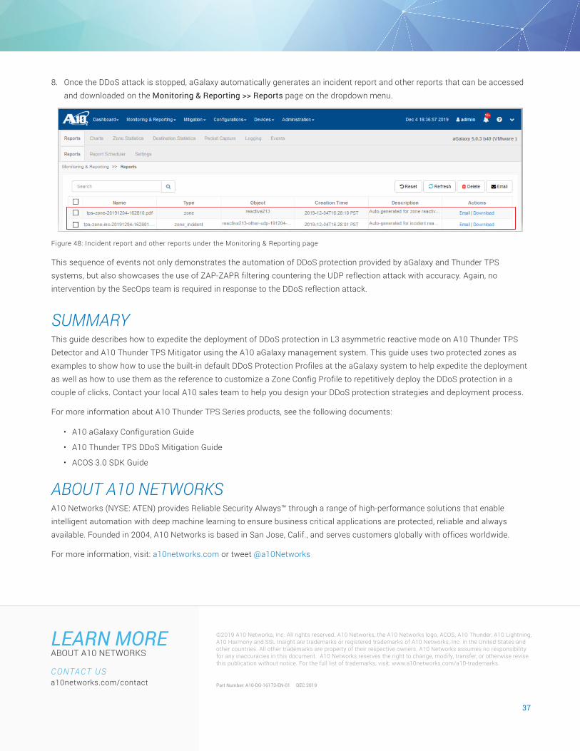
8. Once the DDoS attack is stopped, aGalaxy automatically generates an incident report and other reports that can be accessed and downloaded on the Monitoring & Reporting >> Reports page on the dropdown menu.
Figure 48: Incident report and other reports under the Monitoring & Reporting page
This sequence of events not only demonstrates the automation of DDoS protection provided by aGalaxy and Thunder TPS systems, but also showcases the use of ZAP-ZAPR filtering countering the UDP reflection attack with accuracy. Again, no intervention by the SecOps team is required in response to the DDoS reflection attack.
SUMMARYThis guide describes how to expedite the deployment of DDoS protection in L3 asymmetric reactive mode on A10 Thunder TPS Detector and A10 Thunder TPS Mitigator using the A10 aGalaxy management system. This guide uses two protected zones as examples to show how to use the built-in default DDoS Protection Profiles at the aGalaxy system to help expedite the deployment as well as how to use them as the reference to customize a Zone Config Profile to repetitively deploy the DDoS protection in a couple of clicks. Contact your local A10 sales team to help you design your DDoS protection strategies and deployment process.
For more information about A10 Thunder TPS Series products, see the following documents:
• A10 aGalaxy Configuration Guide
• A10 Thunder TPS DDoS Mitigation Guide
• ACOS 3.0 SDK Guide
ABOUT A10 NETWORKSA10 Networks (NYSE: ATEN) provides Reliable Security Always™ through a range of high-performance solutions that enable intelligent automation with deep machine learning to ensure business critical applications are protected, reliable and always available. Founded in 2004, A10 Networks is based in San Jose, Calif., and serves customers globally with offices worldwide.
For more information, visit: a10networks.com or tweet @a10Networks