deploying the big-ip ltm with multiple big-ip asms · 1 configuring the big-ip ltm with multiple...
TRANSCRIPT
Deploying the BIG-IP Local Traffic Manager with Multiple BIG-IP Application Security Managers
DEPLOYMENT GUIDE Version 2.0

Table of Contents
Table of Contents
Configuring the BIG-IP LTM with multiple BIG-IP ASM devicesWhy deploy multiple ASM devices behind a BIG-IP LTM? .............................................. 1Prerequisites and configuration notes ................................................................................. 1Product versions and revision history ................................................................................. 2Configuration example ............................................................................................................ 2
Configuring the interior BIG-IP LTM system .............................................................................. 5Performing the initial configuration tasks ............................................................................ 5Creating the HTTP health monitor ...................................................................................... 6Creating the pool ...................................................................................................................... 7Creating profiles ........................................................................................................................ 8Creating the virtual server ................................................................................................... 10
Configuring the BIG-IP Application Security Manager ............................................................ 13Performing the initial configuration .................................................................................... 13Creating the pool .................................................................................................................... 13Creating the profiles for ASM .............................................................................................. 14Creating the HTTP class ....................................................................................................... 15Creating the monitoring iRule if using fail-open mode .................................................. 16Creating the virtual server ................................................................................................... 17Creating the security policy ................................................................................................. 18Replicating the configuration on the other BIG-IP ASM devices ................................. 18
Configuring the exterior BIG-IP LTM ......................................................................................... 20Configuring the health monitor ........................................................................................... 20Creating the pool .................................................................................................................... 20Creating the Profiles .............................................................................................................. 21Creating the virtual server ................................................................................................... 22
Configuring the Enterprise Manager to replicate the application security policy ............. 24Discovering the ASM devices ............................................................................................... 24Creating a template for the ASM policy ............................................................................ 25Distributing the template to the other ASM devices ..................................................... 25Adding the ASM virtual servers to the existing pool on the exterior LTM .............. 27Testing and validating the security policy .......................................................................... 27
i
Configuring the BIG-IP LTM with multiple BIG-IP ASM devices
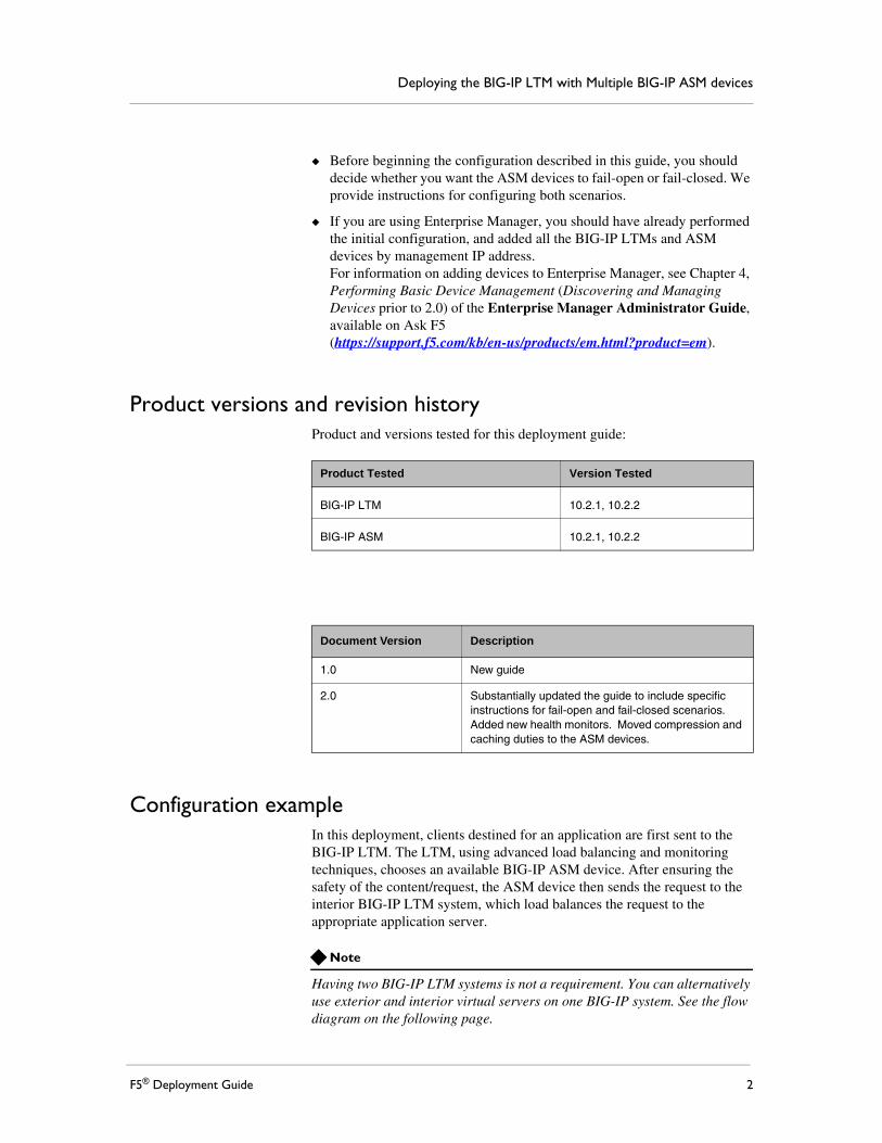
In this deployment guide, we show you how to configure the BIG-IP Local Traffic Manager (LTM) with multiple Application Security Manager (ASM) devices. The guide also includes an optional section on using the F5 Enterprise Manager to make deploying and maintaining the ASM configuration much easier.
The configuration scenario presented in this guide shows how the BIG-IP LTM allows organizations to easily scale ASM deployments to increase total system performance.
For more information on the F5 devices included in this guide, seehttp://www.f5.com/products/
Why deploy multiple ASM devices behind a BIG-IP LTM? The BIG-IP ASM is available as a module on the BIG-IP LTM, as well as a stand alone device. The following list describes some of the reasons that organizations should consider deploying dedicated ASM devices behind a BIG-IP LTM as described in this guide:
◆ PerformanceThe performance of the ASM module on the BIG-IP is sufficient for most implementations; however some organizations may have performance requirements that the module cannot meet. Deploying multiple, dedicated ASM devices behind a BIG-IP LTM delivers a higher performance level.
◆ ScalabilityDeploying dedicated ASM devices behind a BIG-IP LTM allows organizations to scale on demand. When another ASM device is needed, it can easily be added to the BIG-IP LTM pool.
◆ Fail-open modeBy using the BIG-IP LTM in front of the ASM devices, you can operate the ASM in fail-open mode. As long as at least one ASM device is still available, the BIG-IP LTM sends traffic there. In the unlikely event that all ASM devices are unavailable, the traffic is sent directly to the servers.
Prerequisites and configuration notesThe following are general prerequisites for this deployment.
◆ Ensure all devices licenses are installed and ASM is provisioned on the proper devices and that LTM is provisioned on the other devices.
◆ You must get management ports up and configured on all devices to be deployed.
1
Deploying the BIG-IP LTM with Multiple BIG-IP ASM devices
◆ Before beginning the configuration described in this guide, you should decide whether you want the ASM devices to fail-open or fail-closed. We provide instructions for configuring both scenarios.
◆ If you are using Enterprise Manager, you should have already performed the initial configuration, and added all the BIG-IP LTMs and ASM devices by management IP address. For information on adding devices to Enterprise Manager, see Chapter 4, Performing Basic Device Management (Discovering and Managing Devices prior to 2.0) of the Enterprise Manager Administrator Guide, available on Ask F5 (https://support.f5.com/kb/en-us/products/em.html?product=em).
Product versions and revision historyProduct and versions tested for this deployment guide:
Configuration exampleIn this deployment, clients destined for an application are first sent to the BIG-IP LTM. The LTM, using advanced load balancing and monitoring techniques, chooses an available BIG-IP ASM device. After ensuring the safety of the content/request, the ASM device then sends the request to the interior BIG-IP LTM system, which load balances the request to the appropriate application server.
Note
Having two BIG-IP LTM systems is not a requirement. You can alternatively use exterior and interior virtual servers on one BIG-IP system. See the flow diagram on the following page.
Product Tested Version Tested
BIG-IP LTM 10.2.1, 10.2.2
BIG-IP ASM 10.2.1, 10.2.2
Document Version Description
1.0 New guide
2.0 Substantially updated the guide to include specific instructions for fail-open and fail-closed scenarios. Added new health monitors. Moved compression and caching duties to the ASM devices.
F5® Deployment Guide 2
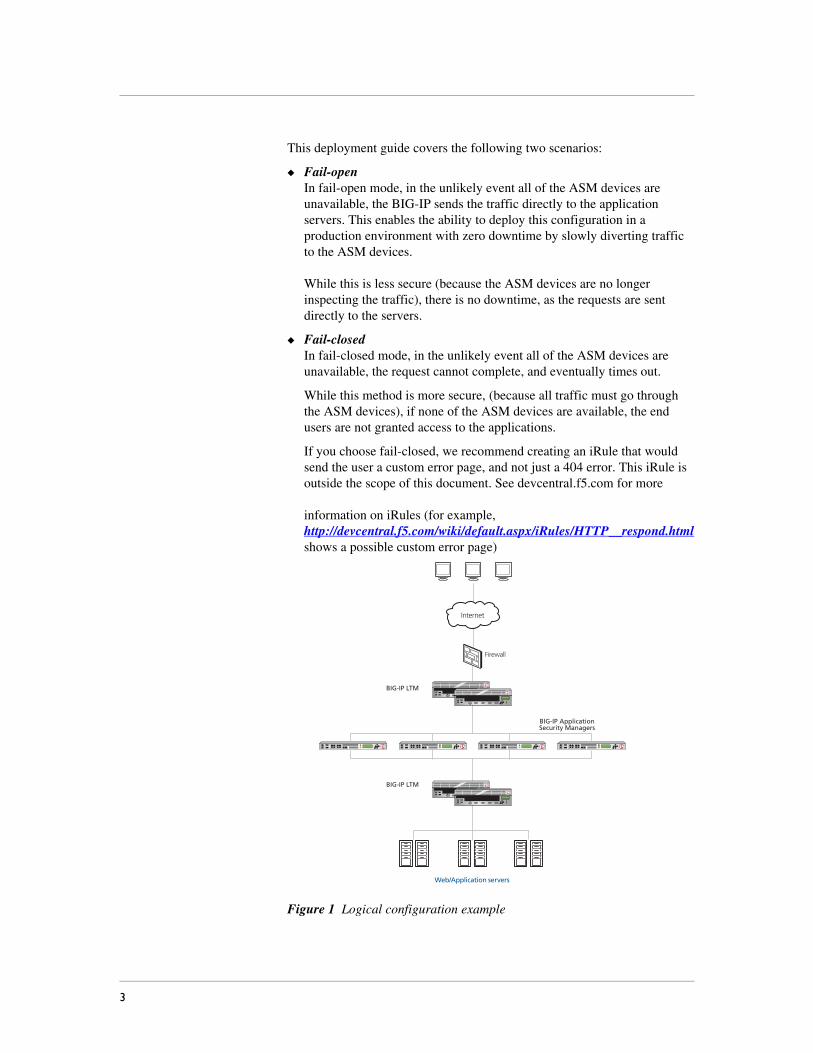
This deployment guide covers the following two scenarios:
◆ Fail-openIn fail-open mode, in the unlikely event all of the ASM devices are unavailable, the BIG-IP sends the traffic directly to the application servers. This enables the ability to deploy this configuration in a production environment with zero downtime by slowly diverting traffic to the ASM devices. While this is less secure (because the ASM devices are no longer inspecting the traffic), there is no downtime, as the requests are sent directly to the servers.
◆ Fail-closedIn fail-closed mode, in the unlikely event all of the ASM devices are unavailable, the request cannot complete, and eventually times out.
While this method is more secure, (because all traffic must go through the ASM devices), if none of the ASM devices are available, the end users are not granted access to the applications.
If you choose fail-closed, we recommend creating an iRule that would send the user a custom error page, and not just a 404 error. This iRule is outside the scope of this document. See devcentral.f5.com for moreinformation on iRules (for example, http://devcentral.f5.com/wiki/default.aspx/iRules/HTTP__respond.html shows a possible custom error page)
Figure 1 Logical configuration example
Firewall
Internet
BIG-IP LTM
BIG-IP ApplicationSecurity Managers
BIG-IP LTM
Web/Application servers
3

Deploying the BIG-IP LTM with Multiple BIG-IP ASM devices
In the following flow diagram, you can see that the connections flow from the exterior client to front end BIG-IP LTM (or exterior virtual server), and then to the ASM, to the back end BIG-IP LTM (or interior virtual server), finally to the web server and flow back to the client along the reverse path.
Figure 2 Deployment guide configuration flow diagram
BIG-IP ASM
BIG-IP LTM
Client
WebApplication
Exteriorvirtual server
Interiorvirtual server
BIG-IP ASM
1
2 3 4
BIG-IP ASM
BIG-IP ASM
F5® Deployment Guide 4
Configuring the interior BIG-IP LTM systemThe deployment guide configuration begins with the interior BIG-IP LTM system configuration, then the BIG-IP ASM configuration, and finally the exterior BIG-IP LTM configuration.
In this section, we configure the BIG-IP LTM system for the internal application(s). In the following procedures, we use a generic web application as an example. You can modify the BIG-IP configuration objects, such as the health monitor and the profiles, to suit your particular application.
Important
If you already have an existing BIG-IP LTM deployment for your applications and want to add the BIG-IP ASM configuration described in this guide, you must modify the HTTP profile for the existing configuration. The HTTP profile must not have compression or caching enabled. The ASM devices need to control the cache.We recommend looking at the Interior BIG-IP LTM configuration as described in this section for guidance on configuration objects for your existing configuration.
Performing the initial configuration tasksBefore creating the application-specific configuration objects, we configure the VLANs and Self IP addresses on the BIG-IP system.
You may already have these objects configured on the BIG-IP system. If so, continue with Creating the HTTP health monitor, on page 6.
Creating the VLANsIn this section, we create VLANs on each BIG-IP device in the configuration.
To create a VLAN
1. On the Main tab, expand Network, and then click VLANs. The VLAN screen opens.
2. In the upper right portion of the screen, click the Create button. The New VLAN screen opens.
3. In the Name box, enter a name for your VLAN. In our example, we use asm-vlan.
4. In the Interface section, from the Available list, click the physical interface associated with this VLAN and click the click the Add button (<< or >>) to move it to the Untagged or Tagged box. Repeat this step as necessary.
5. Click the Finished button.
5
Deploying the BIG-IP LTM with Multiple BIG-IP ASM devices
6. Repeat this procedure on each BIG-IP device in the configuration.
Creating the self IP addressesThe next task is to create a self IP address on the BIG-IP LTM for each of the VLANs you just created.
To create a Self IP address
1. On the Main tab, expand Network, and then click Self IPs.
2. Click the Create button. The New Self IP screen opens.
3. In the IP Address box, type an IP Address for the first VLAN you created. In our example, we use 13.0.0.1.
4. In the Netmask box, enter a netmask for the Self IP. In our example, we use 255.255.255.0
5. From the VLAN list, select the name of the first VLAN you created, In our example, we select asm-vlan.
6. Click the Finished button.
7. Repeat this procedure for each VLAN you created in the preceding procedure.
Creating the HTTP health monitorThe first step is to set up a health monitor for the web application. This procedure is optional, but very strongly recommended. In our example, we create a HTTP health monitor. Choose the monitor that best serves the needs of your application.
This example includes optional steps to use advanced features of this monitor to more accurately determine the health of the application servers. If you chose to use this optional configuration, you must first place a small file on each application server that contains a simple string, such as UP.
To create a health monitor
1. On the Main tab, expand Local Traffic, and then click Monitors.
2. Click the Create button. The New Monitor screen opens.
3. In the Name box, type a name for the Monitor.In our example, we type http-monitor.
4. From the Type list, select http.
5. In the Configuration section, in the Interval and Timeout boxes, type an Interval and Timeout. We recommend at least a (1:3) +1 ratio between the interval and the timeout (for example, the default setting has an interval of 5 and an timeout of 16). In our example, we use a Interval of 15 and a Timeout of 46.
F5® Deployment Guide 6
6. In the Send String box, you can optionally type a Send Sting specific to the device being checked.If you are using the optional monitoring features discussed above, and added a file to your application servers, in the Send String box, use the following syntax, replacing monitor.txt with the appropriate file name:
GET /monitor.txt\r\n
Important: You must have already placed a a small file on each application server that contains a simple string, such as UP.
7. In the Receive String box, if you used a custom Send String, type the expected response. In our example, our file contains the string UP, so we type UP in the Receive String box. Modify the Receive String to contain the string you placed in the file.
8. Click the Finished button.The new monitor is added to the Monitor list.
Creating the poolThe next step is to define a load balancing pool for the application servers. A BIG-IP pool is a set of devices grouped together to receive traffic according to a load balancing method. This pool uses the monitor you just created.
To create the pool
1. On the Main tab, expand Local Traffic, and then click Pools.The Pool screen opens.
2. Click the Create button. The New Pool screen opens.
3. In the Name box, type a name for your pool. In our example, we use application-pool.
4. In the Health Monitors section, select the name of the monitor you created in Creating the HTTP health monitor, and click the Add (<<) button. In our example, we select http-monitor.
5. From the Load Balancing Method list, choose your preferred load balancing method (different load balancing methods may yield optimal results for a particular network).In our example, we select Least Connections (node).
6. In this pool, we leave the Priority Group Activation Disabled.
7. In the New Members section, make sure the New Address option button is selected.
8. In the Address box, add the first server to the pool. In our example, we type 10.132.81.100.
9. In the Service Port box, type 80 or select HTTP from the list.
7
Deploying the BIG-IP LTM with Multiple BIG-IP ASM devices
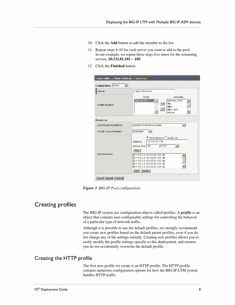
10. Click the Add button to add the member to the list.
11. Repeat steps 8-10 for each server you want to add to the pool. In our example, we repeat these steps five times for the remaining servers, 10.132.81.101 - .105.
12. Click the Finished button.
Figure 3 BIG-IP Pool configuration
Creating profilesThe BIG-IP system use configuration objects called profiles. A profile is an object that contains user-configurable settings for controlling the behavior of a particular type of network traffic.
Although it is possible to use the default profiles, we strongly recommend you create new profiles based on the default parent profiles, even if you do not change any of the settings initially. Creating new profiles allows you to easily modify the profile settings specific to this deployment, and ensures you do not accidentally overwrite the default profile.
Creating the HTTP profileThe first new profile we create is an HTTP profile. The HTTP profile contains numerous configuration options for how the BIG-IP LTM system handles HTTP traffic.
F5® Deployment Guide 8
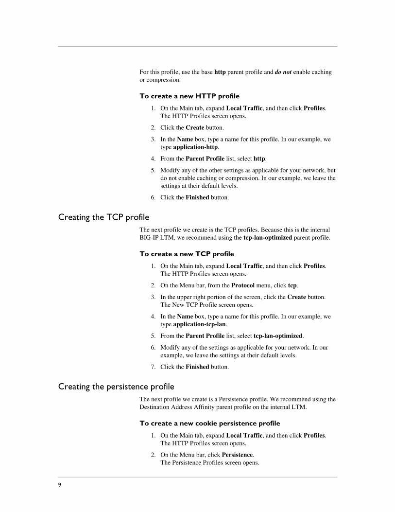
For this profile, use the base http parent profile and do not enable caching or compression.
To create a new HTTP profile
1. On the Main tab, expand Local Traffic, and then click Profiles.The HTTP Profiles screen opens.
2. Click the Create button.
3. In the Name box, type a name for this profile. In our example, we type application-http.
4. From the Parent Profile list, select http.
5. Modify any of the other settings as applicable for your network, but do not enable caching or compression. In our example, we leave the settings at their default levels.
6. Click the Finished button.
Creating the TCP profileThe next profile we create is the TCP profiles. Because this is the internal BIG-IP LTM, we recommend using the tcp-lan-optimized parent profile.
To create a new TCP profile
1. On the Main tab, expand Local Traffic, and then click Profiles.The HTTP Profiles screen opens.
2. On the Menu bar, from the Protocol menu, click tcp.
3. In the upper right portion of the screen, click the Create button. The New TCP Profile screen opens.
4. In the Name box, type a name for this profile. In our example, we type application-tcp-lan.
5. From the Parent Profile list, select tcp-lan-optimized.
6. Modify any of the settings as applicable for your network. In our example, we leave the settings at their default levels.
7. Click the Finished button.
Creating the persistence profileThe next profile we create is a Persistence profile. We recommend using the Destination Address Affinity parent profile on the internal LTM.
To create a new cookie persistence profile
1. On the Main tab, expand Local Traffic, and then click Profiles.The HTTP Profiles screen opens.
2. On the Menu bar, click Persistence.The Persistence Profiles screen opens.
9
Deploying the BIG-IP LTM with Multiple BIG-IP ASM devices
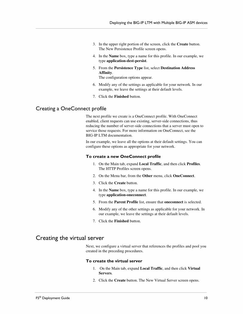
3. In the upper right portion of the screen, click the Create button. The New Persistence Profile screen opens.
4. In the Name box, type a name for this profile. In our example, we type application-dest-persist.
5. From the Persistence Type list, select Destination Address Affinity.The configuration options appear.
6. Modify any of the settings as applicable for your network. In our example, we leave the settings at their default levels.
7. Click the Finished button.
Creating a OneConnect profileThe next profile we create is a OneConnect profile. With OneConnect enabled, client requests can use existing, server-side connections, thus reducing the number of server-side connections that a server must open to service those requests. For more information on OneConnect, see the BIG-IP LTM documentation.
In our example, we leave all the options at their default settings. You can configure these options as appropriate for your network.
To create a new OneConnect profile
1. On the Main tab, expand Local Traffic, and then click Profiles.The HTTP Profiles screen opens.
2. On the Menu bar, from the Other menu, click OneConnect.
3. Click the Create button.
4. In the Name box, type a name for this profile. In our example, we type application-oneconnect.
5. From the Parent Profile list, ensure that oneconnect is selected.
6. Modify any of the other settings as applicable for your network. In our example, we leave the settings at their default levels.
7. Click the Finished button.
Creating the virtual serverNext, we configure a virtual server that references the profiles and pool you created in the preceding procedures.
To create the virtual server
1. On the Main tab, expand Local Traffic, and then click Virtual Servers.
2. Click the Create button. The New Virtual Server screen opens.
F5® Deployment Guide 10
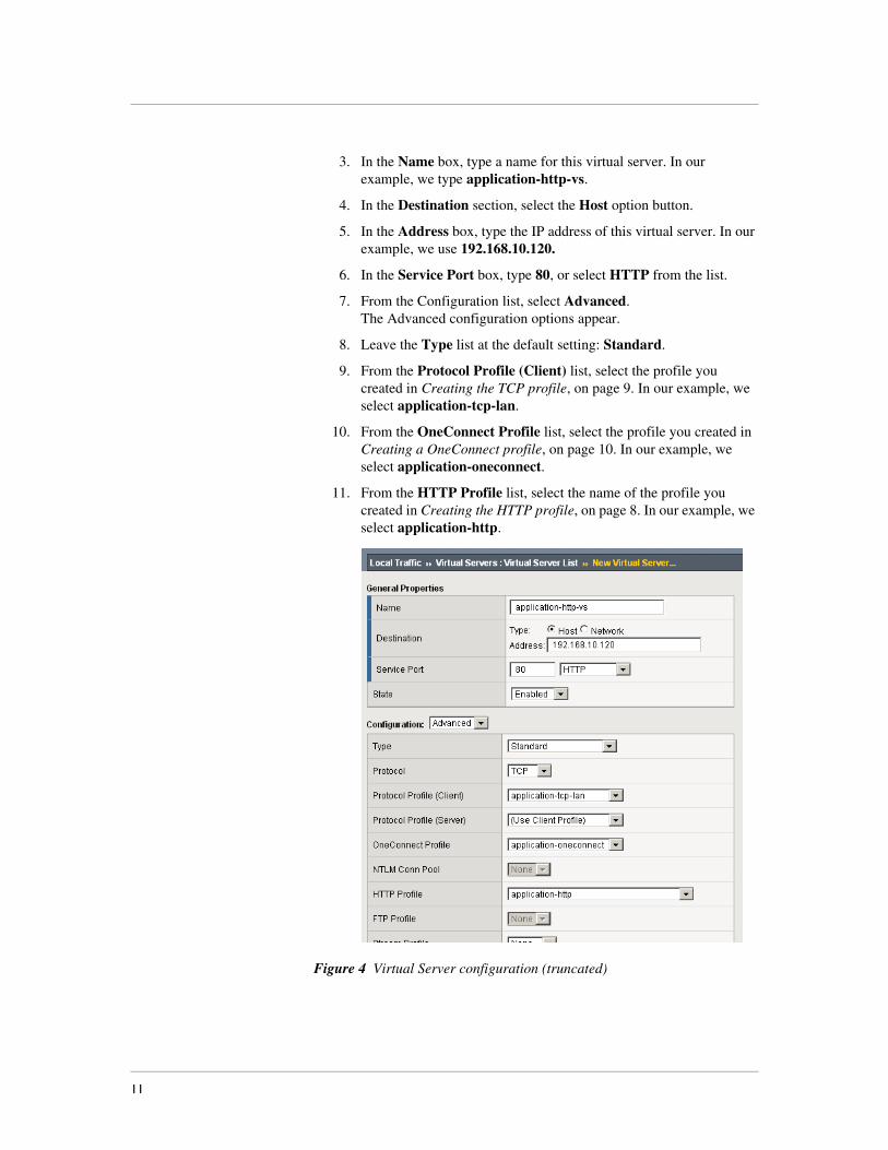
3. In the Name box, type a name for this virtual server. In our example, we type application-http-vs.
4. In the Destination section, select the Host option button.
5. In the Address box, type the IP address of this virtual server. In our example, we use 192.168.10.120.
6. In the Service Port box, type 80, or select HTTP from the list.
7. From the Configuration list, select Advanced.The Advanced configuration options appear.
8. Leave the Type list at the default setting: Standard.
9. From the Protocol Profile (Client) list, select the profile you created in Creating the TCP profile, on page 9. In our example, we select application-tcp-lan.
10. From the OneConnect Profile list, select the profile you created in Creating a OneConnect profile, on page 10. In our example, we select application-oneconnect.
11. From the HTTP Profile list, select the name of the profile you created in Creating the HTTP profile, on page 8. In our example, we select application-http.
Figure 4 Virtual Server configuration (truncated)
11
Deploying the BIG-IP LTM with Multiple BIG-IP ASM devices
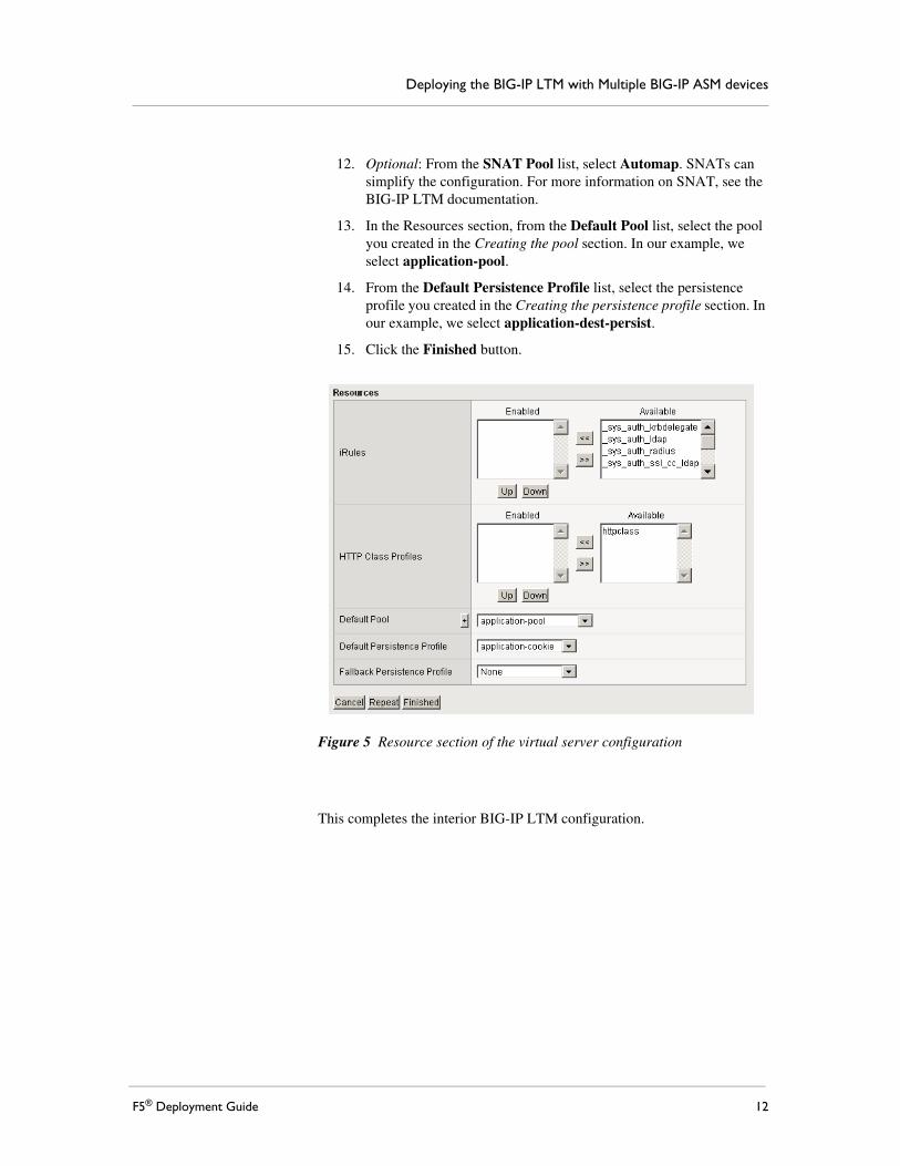
12. Optional: From the SNAT Pool list, select Automap. SNATs can simplify the configuration. For more information on SNAT, see the BIG-IP LTM documentation.
13. In the Resources section, from the Default Pool list, select the pool you created in the Creating the pool section. In our example, we select application-pool.
14. From the Default Persistence Profile list, select the persistence profile you created in the Creating the persistence profile section. In our example, we select application-dest-persist.
15. Click the Finished button.
Figure 5 Resource section of the virtual server configuration
This completes the interior BIG-IP LTM configuration.
F5® Deployment Guide 12
Configuring the BIG-IP Application Security ManagerIn this section, we configure the ASM devices. Because many of the configuration procedures in this section are identical to those you just configured, we refer back to those procedures, noting any unique settings.
Important
You must perform the procedures in this section for each BIG-IP ASM in your configuration.
Performing the initial configurationYou should already have the proper VLANs and Self IPs configured. If you do not, see Performing the initial configuration tasks, on page 5 for specific instructions.
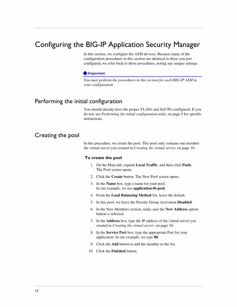
Creating the poolIn this procedure, we create the pool. This pool only contains one member: the virtual server you created in Creating the virtual server, on page 10.
To create the pool
1. On the Main tab, expand Local Traffic, and then click Pools.The Pool screen opens.
2. Click the Create button. The New Pool screen opens.
3. In the Name box, type a name for your pool. In our example, we use application-lb-pool.
4. From the Load Balancing Method list, leave the default.
5. In this pool, we leave the Priority Group Activation Disabled.
6. In the New Members section, make sure the New Address option button is selected.
7. In the Address box, type the IP address of the virtual server you created in Creating the virtual server, on page 10.
8. In the Service Port box, type the appropriate Port for your application. In our example, we type 80.
9. Click the Add button to add the member to the list.
10. Click the Finished button.
13
Deploying the BIG-IP LTM with Multiple BIG-IP ASM devices
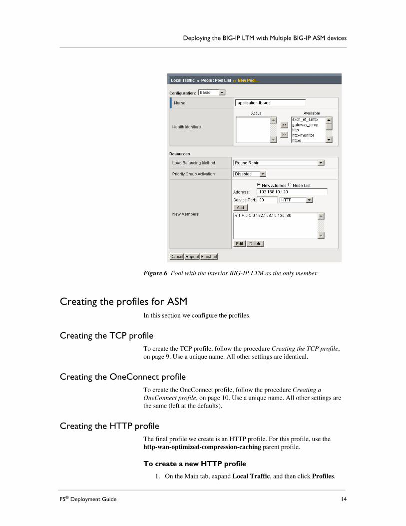
Figure 6 Pool with the interior BIG-IP LTM as the only member
Creating the profiles for ASMIn this section we configure the profiles.
Creating the TCP profileTo create the TCP profile, follow the procedure Creating the TCP profile, on page 9. Use a unique name. All other settings are identical.
Creating the OneConnect profileTo create the OneConnect profile, follow the procedure Creating a OneConnect profile, on page 10. Use a unique name. All other settings are the same (left at the defaults).
Creating the HTTP profileThe final profile we create is an HTTP profile. For this profile, use the http-wan-optimized-compression-caching parent profile.
To create a new HTTP profile
1. On the Main tab, expand Local Traffic, and then click Profiles.
F5® Deployment Guide 14
2. Click the Create button.
3. In the Name box, type a name for this profile. In our example, we type asm-http.
4. From the Parent Profile list, select http-wan-optimized-compression-caching.
5. Modify any of the other settings as applicable for your network, but do not enable caching or compression. In our example, we leave the settings at their default levels.
6. Click the Finished button.
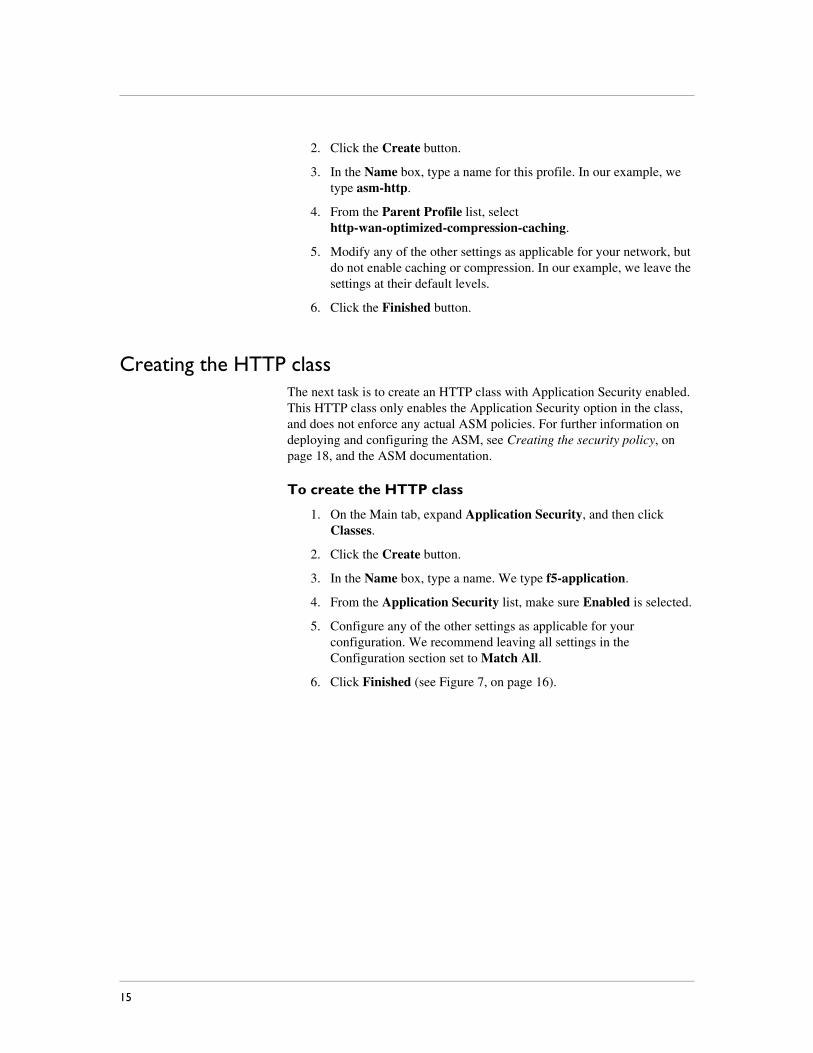
Creating the HTTP classThe next task is to create an HTTP class with Application Security enabled. This HTTP class only enables the Application Security option in the class, and does not enforce any actual ASM policies. For further information on deploying and configuring the ASM, see Creating the security policy, on page 18, and the ASM documentation.
To create the HTTP class
1. On the Main tab, expand Application Security, and then click Classes.
2. Click the Create button.
3. In the Name box, type a name. We type f5-application.
4. From the Application Security list, make sure Enabled is selected.
5. Configure any of the other settings as applicable for your configuration. We recommend leaving all settings in the Configuration section set to Match All.
6. Click Finished (see Figure 7, on page 16).
15
Deploying the BIG-IP LTM with Multiple BIG-IP ASM devices
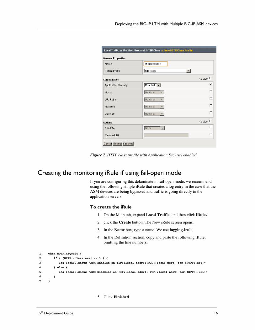
Figure 7 HTTP class profile with Application Security enabled
Creating the monitoring iRule if using fail-open modeIf you are configuring this delaminate in fail-open mode, we recommend using the following simple iRule that creates a log entry in the case that the ASM devices are being bypassed and traffic is going directly to the application servers.
To create the iRule
1. On the Main tab, expand Local Traffic, and then click iRules.
2. click the Create button. The New iRule screen opens.
3. In the Name box, type a name. We use logging-irule.
4. In the Definition section, copy and paste the following iRule, omitting the line numbers:
5. Click Finished.
1
2
3
4
5
6
7
when HTTP_REQUEST {
if { [HTTP::class asm] == 1 } {
log local0.debug "ASM Enabled on [IP::local_addr]:[TCP::local_port] for [HTTP::uri]"
} else {
log local0.debug "ASM Disabled on [IP::local_addr]:[TCP::local_port] for [HTTP::uri]"
}
}
F5® Deployment Guide 16
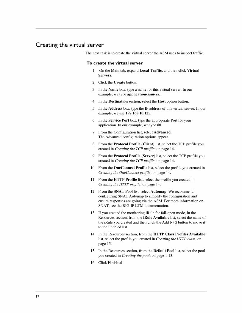
Creating the virtual serverThe next task is to create the virtual server the ASM uses to inspect traffic.
To create the virtual server
1. On the Main tab, expand Local Traffic, and then click Virtual Servers.
2. Click the Create button.
3. In the Name box, type a name for this virtual server. In our example, we type application-asm-vs.
4. In the Destination section, select the Host option button.
5. In the Address box, type the IP address of this virtual server. In our example, we use 192.168.10.125.
6. In the Service Port box, type the appropriate Port for your application. In our example, we type 80.
7. From the Configuration list, select Advanced.The Advanced configuration options appear.
8. From the Protocol Profile (Client) list, select the TCP profile you created in Creating the TCP profile, on page 14.
9. From the Protocol Profile (Server) list, select the TCP profile you created in Creating the TCP profile, on page 14.
10. From the OneConnect Profile list, select the profile you created in Creating the OneConnect profile, on page 14.
11. From the HTTP Profile list, select the profile you created in Creating the HTTP profile, on page 14.
12. From the SNAT Pool list, select Automap. We recommend configuring SNAT Automap to simplify the configuration and ensure responses are going via the ASM. For more information on SNAT, see the BIG-IP LTM documentation.
13. If you created the monitoring iRule for fail-open mode, in the Resources section, from the iRule Available list, select the name of the iRule you created and then click the Add (<<) button to move it to the Enabled list.
14. In the Resources section, from the HTTP Class Profiles Available list, select the profile you created in Creating the HTTP class, on page 15.
15. In the Resources section, from the Default Pool list, select the pool you created in Creating the pool, on page 1-13.
16. Click Finished.
17
Deploying the BIG-IP LTM with Multiple BIG-IP ASM devices
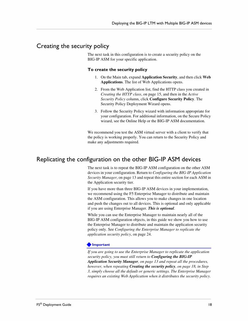
Creating the security policyThe next task in this configuration is to create a security policy on the BIG-IP ASM for your specific application.
To create the security policy
1. On the Main tab, expand Application Security, and then click Web Applications. The list of Web Applications opens.
2. From the Web Application list, find the HTTP class you created in Creating the HTTP class, on page 15, and then in the Active Security Policy column, click Configure Security Policy. The Security Policy Deployment Wizard opens.
3. Follow the Security Policy wizard with information appropriate for your configuration. For additional information, on the Secure Policy wizard, see the Online Help or the BIG-IP ASM documentation.
We recommend you test the ASM virtual server with a client to verify that the policy is working properly. You can return to the Security Policy and make any adjustments required.
Replicating the configuration on the other BIG-IP ASM devicesThe next task is to repeat the BIG-IP ASM configuration on the other ASM devices in your configuration. Return to Configuring the BIG-IP Application Security Manager, on page 13 and repeat this entire section for each ASM in the Application security tier.
If you have more than three BIG-IP ASM devices in your implementation, we recommend using the F5 Enterprise Manager to distribute and maintain the ASM configuration. This allows you to make changes in one location and push the changes out to all devices. This is optional and only applicable if you are using Enterprise Manager. This is optional.
While you can use the Enterprise Manager to maintain nearly all of the BIG-IP ASM configuration objects, in this guide we show you how to use the Enterprise Manager to distribute and maintain the application security policy only. See Configuring the Enterprise Manager to replicate the application security policy, on page 24.
Important
If you are going to use the Enterprise Manager to replicate the application security policy, you must still return to Configuring the BIG-IP Application Security Manager, on page 13 and repeat all the procedures, however, when repeating Creating the security policy, on page 18, in Step 3, simply choose all the default or generic settings. The Enterprise Manager requires an existing Web Application when it distributes the security policy.
F5® Deployment Guide 18

For more information on Enterprise Manager, see http://www.f5.com/products/enterprise-manager/. For more information on how to configure Enterprise Manager for other ASM or LTM objects, see the Enterprise Manager documentation or the online help.
19

Deploying the BIG-IP LTM with Multiple BIG-IP ASM devices
Configuring the exterior BIG-IP LTMIn this section, we configure the exterior BIG-IP LTM for the ASM devices.
Configuring the health monitorFor the exterior LTM health monitor, we use a monitor very similar to the monitor on the interior BIG-IP LTM, with a longer interval and timeout.
Return to Creating the HTTP health monitor, on page 6, and create a new monitor with the following exceptions:
• In Step 3, type a unique name.
• In Step 5, use 45 for the Interval and 136 for the Timeout.
Creating the poolThe next task it to create a pool on the BIG-IP LTM for the ASM virtual server you created in Creating the virtual server, on page 17.
Before beginning the pool configuration, it is important to decide whether you want the ASM devices to fail-open or fail-closed. See the description of the two modes in the Configuration example, on page 2.
To create the pool
1. On the Main tab, expand Local Traffic, and then click Pools.
2. Click the Create button. The New Pool screen opens.
3. From the Configuration list, select Advanced.
4. In the Name box, type a name for your pool. In our example, we use asm-pool.
5. In the Health Monitors section, select the monitor you created, and then click the Add (<<) button.
6. From the Allow SNAT list, make sure that Yes is selected.
7. From the Load Balancing Method list, select Dynamic Ratio.
8. If you are configuring Fail-Open mode only: From the Priority Group Activation list, select Less than, and then in the Available Members box, type 1.
9. In the New Members section, make sure the New Address option button is selected.
a) In the Address box, type the IP address of the ASM virtual server you created in Creating the virtual server, on page 17.
b) In the Service Port box, type 80 or select HTTP from the list.
c) If you are configuring Fail-Open mode only: In the Priority box, type 10.
F5® Deployment Guide 20

d) Click the Add button to add the member to the list.
10. The next step depends on whether you are using the Enterprise Manager to deploy and maintain the ASM configuration.
• If you are NOT using Enterprise Manager:Repeat steps 9-12 for each of the ASM virtual servers you created in the Configuring the BIG-IP Application Security Manager section on page 13.
• If you are using the Enterprise ManagerOnly add the first virtual server you created when configuring the ASM devices. After using the Enterprise Manager to deploy the configuration to all the ASM devices, we return to this virtual server to add the remaining ASM virtual servers. We do this to ensure no traffic is sent to the ASM devices before the configuration is complete.
11. The next step depends on whether you want the ASMs to fail-open or fail-closed as described in the introduction to this section.
• Fail-closedIf you are configuring the ASM devices to fail-closed, no further configuration is necessary, continue to the last step.
• Fail-openIf you are configuring the ASM devices to fail-open, you also add the Application servers to the pool.Return to step 10 and repeat the substeps for each of the application servers with the following exception:In the Priority box, type 5.Important: You must give the application servers a lower priority than the ASM virtual servers.
12. Click the Finished button.
Creating the ProfilesIn this section, we create the exterior BIG-IP LTM profiles.
Creating the HTTP profileFor the exterior virtual server, we use the base http parent profile.Do not enable compression or caching on this profile.
In this profile, we enable inserting the X-Forwarded-For header in order to keep track of the client IP.
To create this profile, use the procedure Creating the HTTP profile, on page 8 with the following exception: From the Insert X-Forwarded-For list, select Enabled.
21
Deploying the BIG-IP LTM with Multiple BIG-IP ASM devices
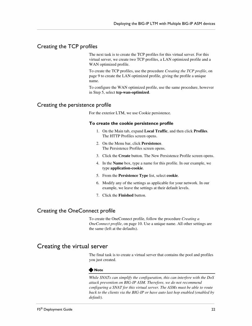
Creating the TCP profilesThe next task is to create the TCP profiles for this virtual server. For this virtual server, we create two TCP profiles, a LAN optimized profile and a WAN optimized profile.
To create the TCP profiles, use the procedure Creating the TCP profile, on page 9 to create the LAN optimized profile, giving the profile a unique name.
To configure the WAN optimized profile, use the same procedure, however in Step 5, select tcp-wan-optimized.
Creating the persistence profileFor the exterior LTM, we use Cookie persistence.
To create the cookie persistence profile
1. On the Main tab, expand Local Traffic, and then click Profiles.The HTTP Profiles screen opens.
2. On the Menu bar, click Persistence.The Persistence Profiles screen opens.
3. Click the Create button. The New Persistence Profile screen opens.
4. In the Name box, type a name for this profile. In our example, we type application-cookie.
5. From the Persistence Type list, select cookie.
6. Modify any of the settings as applicable for your network. In our example, we leave the settings at their default levels.
7. Click the Finished button.
Creating the OneConnect profileTo create the OneConnect profile, follow the procedure Creating a OneConnect profile, on page 10. Use a unique name. All other settings are the same (left at the defaults).
Creating the virtual serverThe final task is to create a virtual server that contains the pool and profiles you just created.
Note
While SNATs can simplify the configuration, this can interfere with the DoS attack prevention on BIG-IP ASM. Therefore, we do not recommend configuring a SNAT for this virtual server. The ASMs must be able to route back to the clients via the BIG-IP or have auto last hop enabled (enabled by default).
F5® Deployment Guide 22
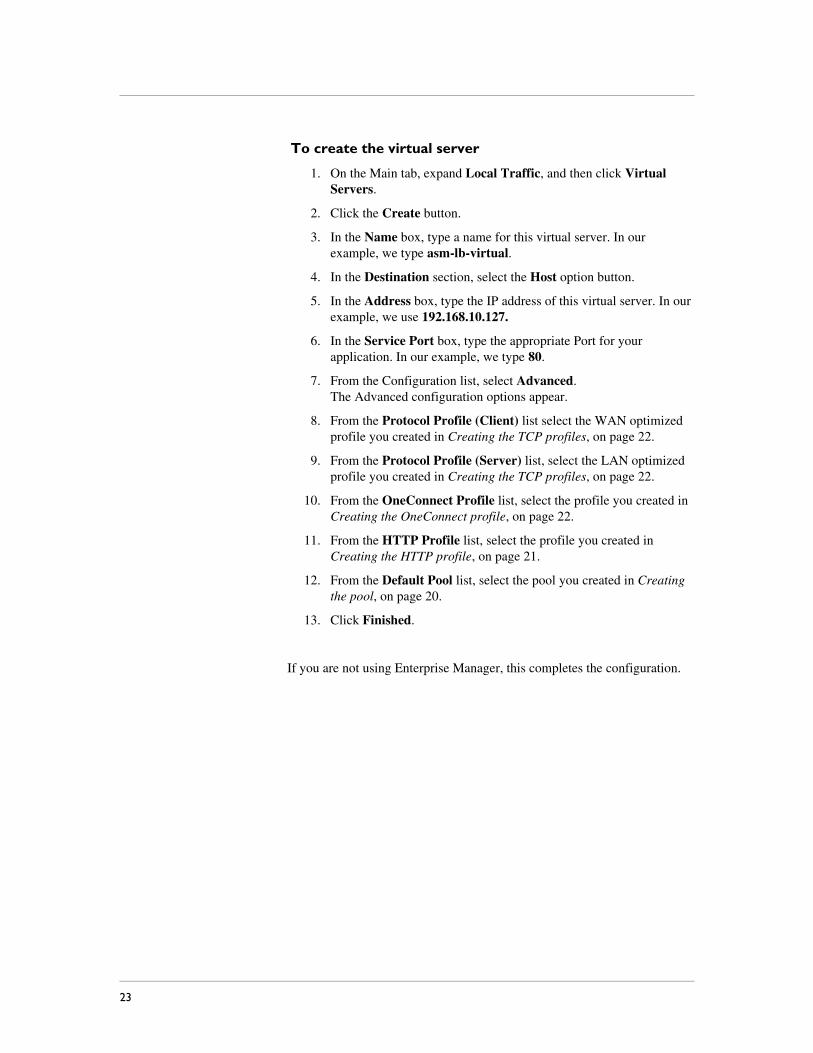
To create the virtual server
1. On the Main tab, expand Local Traffic, and then click Virtual Servers.
2. Click the Create button.
3. In the Name box, type a name for this virtual server. In our example, we type asm-lb-virtual.
4. In the Destination section, select the Host option button.
5. In the Address box, type the IP address of this virtual server. In our example, we use 192.168.10.127.
6. In the Service Port box, type the appropriate Port for your application. In our example, we type 80.
7. From the Configuration list, select Advanced.The Advanced configuration options appear.
8. From the Protocol Profile (Client) list select the WAN optimized profile you created in Creating the TCP profiles, on page 22.
9. From the Protocol Profile (Server) list, select the LAN optimized profile you created in Creating the TCP profiles, on page 22.
10. From the OneConnect Profile list, select the profile you created in Creating the OneConnect profile, on page 22.
11. From the HTTP Profile list, select the profile you created in Creating the HTTP profile, on page 21.
12. From the Default Pool list, select the pool you created in Creating the pool, on page 20.
13. Click Finished.
If you are not using Enterprise Manager, this completes the configuration.
23
Deploying the BIG-IP LTM with Multiple BIG-IP ASM devices
Configuring the Enterprise Manager to replicate the application security policy
Although optional, we strongly recommend using the F5 Enterprise Manager to deploy and maintain the implementation. Enterprise Manager allows you to create a changeset (configuration template) that can be adapted and deployed across all BIG-IP systems in this configuration. This saves and considerable amount of time and reduces misconfiguration over configuring each device individually. For more information on Enterprise Manager, see http://www.f5.com/products/enterprise-manager/.
While you can use the Enterprise Manager to maintain nearly all of the BIG-IP ASM configuration objects, in this guide we only show you how to use the Enterprise Manager to distribute and maintain the application security policy across multiple ASMs, using a central management console. For specific instructions on configuring Enterprise Manager for other ASM or LTM objects, see the Enterprise Manager documentation or the online help.
Note
We assume you have already created a blank Web Application on each of the additional ASM devices, as described in Replicating the configuration on the other BIG-IP ASM devices, on page 18.
Discovering the ASM devices The first task in configuring the Enterprise Manager is to discover all the ASM devices that are a part of this deployment.
To discover the ASM devices
1. On the Main tab, expand Enterprise Management, and then click Devices.
2. Click the Discover button.
3. Leave the Scan Type list set to Address List.
4. In the IP Address box, type the management IP address of the first BIG-IP ASM.
5. In the User Name and Password boxes, type the appropriate user name and password to log on to the device.
6. Click the Add button.
7. Repeat steps 4-6 for each of the ASM devices part of this configuration.
8. Click Discover.
The Enterprise Manager discovers each of the ASM devices and adds them to the Device List.
F5® Deployment Guide 24
Creating a template for the ASM policyThe next task is to create the ASM template that contains the security policy you will push to the other ASM devices.
To create the template
1. On the Main tab, expand Enterprise Management, and then click Templates.
2. Click the Create button.
3. In the Name box, type a name for your template. In our example we type f5-application-template. You can optionally type a description.
4. Leave the Source list, set to Device.
5. From the Device list, select the device on which you configured the Application Security Policy in Creating the security policy, on page 18.
6. If applicable, from the Partition list, select the appropriate partition. In our example, we leave this set to Common.
7. Click Next. The Step 2: Class Selection page opens.
8. In the Path List section, from the Available list, select ASM/Policy Template and then click the Add (<<) button.
9. Click Next. The Step 3: Object Selection page opens.
10. In the Object List section, from the Available list, select the completed Application Security policy you created in Creating the security policy, on page 18 and then click the Add (<<) button.
11. Click Next.
12. Review the Template Summary and then click Next. The Template Properties page opens.
13. You can modify the Template Properties as applicable, but do NOT modify the Template Text.
14. Click Next. The Step 6: Template Variable Properties page opens.
15. Verify the Variable properties. You can optionally click Preview to preview the template.
16. Click Finish.
Distributing the template to the other ASM devicesThe next task is to distribute the Application Security Policy template you just created to the other ASM devices in this configuration. The Enterprise Manager uses Changesets to push out the configuration.
25
Deploying the BIG-IP LTM with Multiple BIG-IP ASM devices
To distribute the template
1. On the Main tab, expand Enterprise Management, and then click Changesets.
2. Click the Create button.
3. In the Name box, type a name for this Changeset. In our example, we type f5-application-changeset.
4. From the Source select Template.
5. Click the button for the template you created in Creating a template for the ASM policy, on page 25. In our example, we click f5-application-template.
6. Verify the Template Text. You should not need to modify the template at this point.
7. Click Next.
8. Review the Text of the Changeset, but do not make changes.
9. You have two choices for the last step: to deploy the changeset or to save it on the Enterprise Manager to deploy at a later time.
• If you want to immediately deploy the Changeset, click the Stage for Deployment button.
a) On the Target Device Select page, check the boxes for all the other ASM devices in this configuration and then click Next.
b) On the Device Partition Selection page, select the appropriate partitions and then click Next.
c) Type a Description of this Changeset.
d) We recommend leaving the Create Archive(s) and Archive Options list at the default level. This creates a backup of the existing configuration before implementing the Changeset.
e) Click Deploy Staged Changeset now. You could also click Save Staged Changeset to deploy it later, or click Verify to verify the Changeset.
• If you want to save the Changeset and deploy it at a later time, click Finish.
Important
If you application security configuration uses flows or objects, login to each ASM and replicate the configuration from the first ASM. This must be done before you add the ASM virtual server to the pool on the external BIG-IP LTM.
F5® Deployment Guide 26
Adding the ASM virtual servers to the existing pool on the exterior BIG-IP LTM
With the ASM configuration now complete, we return to the pool on the exterior BIG-IP LTM system you created in Creating the pool, on page 20, and add the remaining ASM virtual servers.
To add the remaining ASM virtual servers to the pool
1. On the Main tab of the exterior BIG-IP LTM system, expand Local Traffic, and then click Pools.
2. Click the Pool you created in Creating the pool, on page 20. In our example, we click asm-pool. You see the General Properties of the pool.
3. On the Menu bar, click Members.
4. In the Current Members section, click the Add button. The New Pool Members page opens.
5. In the Address box, type the address of an ASM virtual server.
6. In the Port box, type the appropriate port.
7. Click the Repeat button and repeat steps 5-7 for each of the remaining ASM virtual servers.
8. Click Finished when you have added all of the ASM virtual servers.
Testing and validating the security policyWe strongly recommend you test and validate that each ASM device has the proper security policy from the template and validate that the ASM is performing as expected.
When testing and validation has passed we recommend creating a configuration archive of each device and pinning this on the EM. For more information on storing archives on the Enterprise Manager, see the product documentation.
27