deployment guide: carrier grade nat (cgn - a10 networks
TRANSCRIPT

LARGE SCALE NETWORK ADDRESS TRANSLATIONHOW TO CONFIGURE LARGE SCALE NAT (LSN) ON A10 THUNDER/VTHUNDER CGN DEVICES
DEPLOYMENT GUIDE

OVERVIEW In 2011, the Internet Assigned Numbers Authority (IANA) issued the last remaining /8 address blocks to the Regional Internet Registries, leaving the RIRs in control of assigning the remaining available IPv4 addresses. This posed a problem for Internet Service Providers (ISPs) to continue obtaining unallocated IPv4 address space, forcing a plan of action both to preserve the remaining IPv4 address space and to provide a mechanism for IPv6 translation. Many technologies have emerged to solve this problem, including NAT444, DS-Lite and 6rd; all of which are based upon a common foundation of Carrier Grade Network Address Translation (CGNAT).
The A10 Networks® Thunder® Series is a family of both hardware and software appliances ready to match any deployment needed. The Carrier Grade Networking gateways have been designed to extend the service life of IPv4 infrastructure and provide a seamless migration to IPv6 networks. A10 Thunder CGN also comes with integrated Distributed Denial of Service (DDoS) protection of IP address pools to effectively eliminate targeted attacks. Thunder CGN software and hardware features together ensure maximum uptime of network resources to process subscriber traffic.
This guide provides a basis for understanding the A10 Thunder CGN implementation, and includes an overview of the solution, design, scaling considerations and overall system configuration with optional features including traffic logging.
Note: Sometimes CGNAT is also called Large Scale NAT (LSN), and this is the term used in the IETF documents referenced in this document.
TALK WITH A10CONTACT USa10networks.com/contact

OVERVIEW ......................................................................................................................................................................................................................................................2CARRIER GRADE NAT .............................................................................................................................................................................................................................4DEPLOYMENT PREREQUISITES ...................................................................................................................................................................................................... 4 Access to A10 Thunder CGN......................................................................................................................................................................................................................4
ConfiguretheManagementInterface ......................................................................................................................................................................................................4
BASE CONFIGURATION .........................................................................................................................................................................................................................5 Reference Topology .....................................................................................................................................................................................................................................5
INTERFACE CONFIGURATION ...........................................................................................................................................................................................................6NETWORK INTEGRATION ..................................................................................................................................................................................................................10 Static Route Deployment ..........................................................................................................................................................................................................................10
Dynamic Routing ........................................................................................................................................................................................................................................10
VRRP-A CONFIGURATION .................................................................................................................................................................................................................11CGNAT CONFIGURATION (DYNAMIC LSN) .............................................................................................................................................................................15 CGNATConfigurationSteps .....................................................................................................................................................................................................................15
CONFIGURING FIXED-NAT (DETERMINISTIC NAT) ...........................................................................................................................................................21 Fixed-NATConfigurationSteps................................................................................................................................................................................................................21
LOGGING CONFIGURATION .............................................................................................................................................................................................................24 LoggingConfigurationSteps....................................................................................................................................................................................................................24
ADVANCED CONFIGURATION OPTIONS ..................................................................................................................................................................................27 LoggingConfigurationSteps....................................................................................................................................................................................................................27
Endpoint-Independent Mapping/Endpoint-Independent Filtering .....................................................................................................................................................27
Static Mapping ............................................................................................................................................................................................................................................29
Override Actions for Class-List Matches ................................................................................................................................................................................................29
NAT IP Address Selection .........................................................................................................................................................................................................................30
Hairpinning ..................................................................................................................................................................................................................................................30
User Quotas .................................................................................................................................................................................................................................................31
The Application Layer Gateway ...............................................................................................................................................................................................................32
Protocol Port Overloading.........................................................................................................................................................................................................................33
CGNAT Timeouts ........................................................................................................................................................................................................................................35
System Resource Allocation ....................................................................................................................................................................................................................37
Advanced CGNAT Logging .......................................................................................................................................................................................................................38
CRITICAL DDOS MITIGATION FEATURES ................................................................................................................................................................................48 IP Anomaly Filters ......................................................................................................................................................................................................................................48
Connection Rate Limiting .........................................................................................................................................................................................................................50
Selective Filtering For LSN .......................................................................................................................................................................................................................52
SUMMARY...................................................................................................................................................................................................................................................54APPENDIX ...................................................................................................................................................................................................................................................55ABOUT A10 NETWORKS ....................................................................................................................................................................................................................59
TABLE OF CONTENTS
DISCLAIMER
This document does not create any express or implied warranty about A10 Networks or about its products or services, including but not limited to fitness for a particular use and noninfringement. A10 Networks has made reasonable efforts to verify that the information contained herein is accurate, but A10 Networks assumes no responsibility for its use. All information is provided “as-is.” The product specifications and features described in this publication are based on the latest information available; however, specifications are subject to change without notice, and certain features may not be available upon initial product release. Contact A10 Networks for current information regarding its products or services. A10 Networks’ products and services are subject to A10 Networks’ standard terms and conditions.

4
CARRIER GRADE NAT CGNAT provides a methodology for preserving IPv4 addresses by centralizing public address resources and sharing those resources across a large user community. Carrier Grade NAT offers the following advantages over traditional Network Address Translation (NAT) operations:
• High Transparency
CGNAT implements several features to provide a seamless user experience across an NAT environment, including Endpoint-Independent Mapping (EIM), Endpoint-Independent Filtering (EIF), address pooling, hairpinning and port preservation. These features provide a transparent client access environment to outside resources, thus insuring that both client-server and peer-to-peer applications continue to function as designed.
• Well-Defined Behavior
CGNAT is a mature technology whose operation is well standardized by several IETF RFCs and draft documents, including the following:
• BEHAVE-TCP (RFC 5382)
• BEHAVE-UDP (RFC 4787)
• BEHAVE-ICMP (RFC 5508)
• CGN (draft-nishitani-cgn-05)
These RFCs provide a foundation for application transparency and they formalize CGNAT behavior to facilitate future application development.
• Fairness and Resource Sharing
The A10 Networks CGNAT implementation provides limits at both session and user levels in order to control the amount of allocated resources. This ensures that resources are distributed fairly across the user base in accordance with the service provider’s requirements.
• Log File Size Management
CGNAT implementations can create large amounts of logging data in service provider networks. A10 Networks’ implementation provides many logging techniques to limit both the number of log entries and their size.
DEPLOYMENT PREREQUISITESTo deploy a CGNAT solution, the following are required:
• A10 Networks Thunder CGN (hardware appliance) or vThunder CGN (virtual appliance)
• A10 Networks Advanced Core Operating System (ACOS®) 4.1 or higher
• Access routers and gateway routers
- (optional) Customer premises equipment (CPE) device to provide NAT for client network using NAT444 topology
Note: For this deployment, vThunder CGN is running on ESXi 5.5.hypervisor.
To deploy a CGNAT solution using ACOS 2.8.x release, please refer to the guide A10 Thunder Series and AX Series.

5
BASE CONFIGURATIONCGN general architecture consists of an access network (addressed with RFC 6598 reserved address 100.64.0.0/10), an aggregation routing layer, Thunder CGN devices, and peering routers egressing to the public Internet. For business or residential customers that are directly connected to the access network, there is only one level of NAT (NAT44) required. These customers receive an address directly from the 100.64.0.0/10 subnet. Typically, residential customers deploy a gateway device that implements NAT, creating the NAT444 model. The clients use private addresses from the RFC 1918 IP address space. The private addresses are translated into addresses in the 100.64.0.0/10 subnet, which is configured within the ISP access infrastructure. Client (end user) traffic then is routed through an aggregation layer to the assigned Thunder CGN device, and then translated into IPv4 public addresses. CGN deployment is transparent to end users and requires no configuration changes to customer-premise equipment (CPE) or hosts.
CONFIGURE THE MANAGEMENT INTERFACEConfigure the management interface at the global configuration level using the following commands:
ACOS#configure terminal
ACOS(config)#interface management
ACOS(config-if:management)#ip address 10.100.14.56 255.255.255.0
ACOS(config-if:management)#ip default-gateway 10.100.14.1
ACOS(config-if:management)#ip control-apps-use-mgmt-port
Note: Use the enable-management service command to enable management services for Ethernet ports.
ACOS(config)#enable-management service
ACCESS TO A10 THUNDER CGNLog into the Thunder CGN CLI, using the console port or an SSH to a dedicated management port.
• The default login credential is:
- Username: admin Password: a10
• The default IP address is 172.31.31.31.
login as: admin
Use keyboard-interactive authentication
Password:
Last login: Fri Jun 16 00:10:46 2017 from 10.254.101.182
ACOS system is ready now.
Type ? for help]

6
The configuration example depicted in Figure 1 illustrates a NAT44 deployment and consists of two Windows clients directly connected to the service provider’s network without a CPE NAT router. Therefore, each client receives an address from the reserved 100.64.0.0/10 subnet (RFC 6598). Client-1 is configured for dynamic CGNAT mapping, and Client-2 uses Fixed-NAT mapping. The aggregation router is connected to a CGN device (Thunder CGN) through L2 switch using Link Aggregation Control Protocol (LACP) link aggregation. Finally, the Thunder CGN device is connected to the BGP peering router, providing connection to the Internet.
This example uses dynamic routing protocols to redistribute the NAT pool. OSPF is used between the aggregation router and the Thunder CGN device; BGP is configured between the BGP peering router and the Thunder CGN device. The BGP peering router injects a default route towards the Thunder CGN device and the Thunder CGN device injects the configured NAT pool subnets, with the next hop to the outside IP address 10.200.2.2. The Thunder CGN device also injects a default route (using OSPF) towards the aggregation router. The next hop must be modified to represent the inside IP 100.64.1.2.
To further clarify, here is a packet walkthr ough of the topology:
1. Client-1 generates a TCP-SYN packet and sends it to the aggregation router, 100.64.100.2.
2. The aggregation router uses the default route to forward the packet to the Thunder CGN device’s IP address, 10.64.1.2 on inside VLAN 31.
3. The Thunder CGN device receives the packet and finds a match in the class list configured for dynamic mapping. It then creates an NAT binding and replaces the source address with one that is selected from the NAT pool.
4. The Thunder CGN device sends the packet to a BGP peering router over outside VLAN 20, and the packet is then forwarded to its destination.
5. The destination returns a SYN-ACK to the BGP peering router. This router has a BGP route to the NAT pool subnet’s next hop IP address 10.200.2.2 in VLAN 20.
6. The Thunder CGN device receives the packet, consults the NAT bindings, replaces the destination address with that of Client-1, and routes the packet towards the aggregation router on inside VLAN 31.
7. The aggregation router sends the packet to Client-1.
Figure 1: CGN reference topology
REFERENCE TOPOLOGY
BGP Peering Router
Client-1VLAN 401
100.64.100.1
VLAN 401100.64.100.2
VLAN 31100.64.1.4
VLAN 402100.64.101.2
Client-2VLAN 402
100.64.10.1
L2 Aggregation Switch
L3 Aggregation Router
Thunder CGN
Thunder CGN
Internet
Eth 1VLAN 31
100.64.1.2
Eth 1VLAN 31
100.64.1.3
Eth 2VLAN 20
10.200.2.2
Eth 2VLAN 20
10.200.2.3
Eth 3VLAN 3010.200.1.1
Eth 3VLAN 3010.200.1.2
VLAN 2010.200.2.10
Floating IPInside:100.64.1.1
Outside:10.200.2.1
LACP
LACP
7
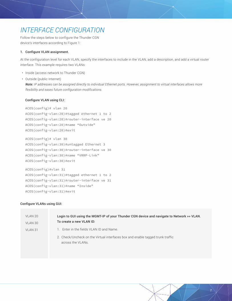
INTERFACE CONFIGURATIONFollow the steps below to configure the Thunder CGN device’s interfaces according to Figure 1:
1. Configure VLAN assignment.
At the configuration level for each VLAN, specify the interfaces to include in the VLAN, add a description, and add a virtual router interface. This example requires two VLANs:
• Inside (access network to Thunder CGN)
• Outside (public Internet) Note: IP addresses can be assigned directly to individual Ethernet ports. However, assignment to virtual interfaces allows more flexibility and eases future configuration modifications.
Configure VLAN using CLI:
ACOS(config)# vlan 20
ACOS(config-vlan:20)#tagged ethernet 1 to 2
ACOS(config-vlan:20)#router-interface ve 20
ACOS(config-vlan:20)#name “Outside”
ACOS(config-vlan:20)#exit
ACOS(config)# vlan 30
ACOS(config-vlan:30)#untagged Ethernet 3
ACOS(config-vlan:30)#router-interface ve 30
ACOS(config-vlan:30)#name “VRRP-Link”
ACOS(config-vlan:30)#exit
ACOS(config)#vlan 31
ACOS(config-vlan:31)#tagged ethernet 1 to 2
ACOS(config-vlan:31)#router-interface ve 31
ACOS(config-vlan:31)#name “Inside”
ACOS(config-vlan:31)#exit
Configure VLANs using GUI:
Login to GUI using the MGMT-IP of your Thunder CGN device and navigate to Network >> VLAN. To create a new VLAN ID:
1. Enter in the fields VLAN ID and Name.
2. Check/Uncheck on the Virtual interfaces box and enable tagged trunk traffic across the VLANs.
VLAN 20
VLAN 30
VLAN 31

8
2. Set the physical interface attributes. For this example, link aggregation is used.
Configure Ethernet ports using CLI:
ACOS(config-if:management)#interface ethernet
ACOS(config-if:ethernet1)#enable
ACOS(config-if:ethernet1)#trunk-group 1 lacp
ACOS(config-if:ethernet:1-trunk-group:1)#lacp timeout long
ACOS(config-if:management)#interface ethernet 2
ACOS(config-if:ethernet2)#enable
ACOS(config-if:ethernet2)#trunk-group 1 lacp
ACOS(config-if:ethernet:2-trunk-group:1)#lacp timeout long
Configure Ethernet ports using GUI:
3. Assign an IP address to the virtual router interface of each VLAN.
Configure Virtual Ethernet Interfaces using CLI:
AACOS(config)#interface ve 20
ACOS(config-if:ve20)#ip address 10.200.2.2 255.255.255.0
ACOS(config-if:ve20)#ip nat outside
ACOS(config-if:ve20)#enable
ACOS(config-if:ve20)#exit
ACOS(config)#interface ve 30
ACOS(config-if:ve20)#ip address 10.200.1.1 255.255.255.0
ACOS(config-if:ve20)#enable
ACOS(config-if:ve20)#exit
ACOS(config)#interface ve 31
ACOS(config-if:ve31)#ip address 100.64.1.2 255.255.255.0
ACOS(config-if:ve31)#ip nat inside
ACOS(config-if:ve31)#enable
ACOS(config-if:ve31)#exit
Navigate to Network >> Interfaces and edit the ports to be configured as trunk ports:
1. Set load interval and Internet Control Message Protocol (ICMP) rate limit (optional).
2. Check/Uncheck on Configure Trunk port (under Trunk group).
3. Enable Trunk type as LACP and enter the Trunk Interface number.
4. Set Trunk Mode as active/passive based on the connected interface Trunk Mode and the Timeout as long/short.
Ethernet1,
Ethernet 2
Note: Interfacesdefaulttothedisabledstate.Toenableaninterface,usetheEnablecommandattheconfigurationlevelfortheinterface.

9
Navigate to Network >> interfaces >> Virtual Ethernets and edit the virtual interfaces:
1. Set MTU (optional) and enable the virtual interface.
2. Set IPv4 Address and Netmask as 10.200.2.2 /24 respectively.
1. Set MTU (optional) and enable the virtual interface.
2. Set IPv4 Address and Netmask as 10.200.1.1 /24 respectively.
1. Set MTU (optional) and enable the virtual interface.
2. Set IPv4 Address and Netmask as 100.64.1.2 /24 respectively.
VE20
VE30
VE31
Configure IP address to the virtual router interfaces using GUI:
Verify the interface configuration using CLI:
• show interfaces brief
• show vlans
• show trunk
Output examples for each command are shown below.
To verify that the interfaces are up:
ACOS#show interfaces brief
Port Link Dupl Speed Trunk Vlan MAC IP Address IPs Name
mgmt Up Full 1000 N/A N/A 000c.290c.ab78 10.100.14.56/24 1
1 Up Full 10000 1 Tag 000c.290c.ab82 0.0.0.0/0 0
2 Up Full 10000 1 Tag 000c.290c.ab8c 0.0.0.0/0 0
3 Up N/A 10000 None 30 000c.290c.ab96 0.0.0.0/0 0
ve20 Up N/A N/A N/A 20 000c.290c.ab96 10.200.2.2/24 1
ve30 Up N/A N/A N/A 30 000c.290c.ab82 10.200.1.1/24 1
ve31 Up N/A N/A N/A 31 000c.290c.ab8c 100.64.1.2/24 1
lo1 Up N/A N/A N/A N/A N/A 17.17.17.17/32 1

10
To verify the VLAN configuration:
ACOS#show vlans
Total VLANs: 4
VLAN 1, Name [DEFAULT VLAN]:
Untagged Ethernet Ports: None
Tagged Ethernet Ports: None
Untagged Logical Ports: None
Tagged Logical Ports: None
VLAN 20, Name [Outside]:
Untagged Ethernet Ports: None
Tagged Ethernet Ports: 1 2
Untagged Logical Ports: None
Tagged Logical Ports: None
Router Interface: ve 20
VLAN 30, Name [VRRP-Link]:
Untagged Ethernet Ports: 3
Tagged Ethernet Ports: None
Untagged Logical Ports: None
Tagged Logical Ports: None
Router Interface: ve 30
VLAN 31, Name [Inside]:
Untagged Ethernet Ports: None
Tagged Ethernet Ports: 1 2
Untagged Logical Ports: None
Tagged Logical Ports: None
Router Interface: ve 31
To verify link aggregation:
ACOS#show trunk
Trunk ID : 1 | Member Count: 2
Trunk Name : None
Trunk Status : Up
Trunk Type : Dynamic (LACP)
Admin Key : 1001
Members : 1 2
Cfg Status : Enb Enb
Oper Status : Up Up
Ports-Threshold : 2 Timer: 100 sec(s) Running: No
Working Lead : 2
Note: To verify Virtual Ethernet IP addresses, you can alternatively use the “show ip interface” command.

11
NETWORK INTEGRATIONThis section provides information and best practices for integrating the Thunder CGN device into static and dynamically routed environments.
STATIC ROUTE DEPLOYMENTThunder CGN devices support all major routing protocols, providing a flexible framework that integrates into networking environments with minimal disruption. Alternatively, some service providers may choose to use static routing from access networks to the Thunder CGN device and outwards towards the Internet.
For Figure 1, the following static routes can be configured:
• The Thunder CGN device should have a static route to 100.64.100/24 and 100.64.101/24, with next hop 100.64.1.4 (the IP address of the access router).
• The Thunder CGN device should have a default route to the external peering router, 10.200.2.10.
• The external router should have a route to NAT pool 192.0.2.32/27, with next hop 10.200.2.2.
DYNAMIC ROUTINGThe example in Figure 1 uses dynamic routing for reachability. BGP is enabled between the external peering router and the CGNAT device, and OSPF is enabled between the CGNAT device and the access router.
The following additional options should be configured to enable route redistribution.
1. Configure the upstream router to originate default route(s) towards the Thunder CGN device.
BGP(config)#router bgp 65000
BGP(config-bgp:65000)#neighbor 10.200.2.1 remote-as 65000
BGP(config-bgp:65000)#neighbor 10.200.2.1 default-originate
BGP(config-bgp:65000)#exit
2. Configure the Thunder CGN device to redistribute the NAT pool through BGP to the peering router, 10.200.2.10. Use the redistribute IP-NAT command (at the BGP configuration level) to distribute the NAT pool to all BGP peers.
ACOS(config)#route-map nat_redis permit 1
ACOS(config-route-map:1)#set ip next-hop 10.200.2.1
ACOS(config-route-map:1)#exit
ACOS(config)#router bgp 65000
ACOS(config-bgp:65000)#neighbor 10.200.2.10 remote-as 65000
ACOS(config-bgp:65000)#neighbor 10.200.2.10 update-source 10.200.2.1
ACOS(config-bgp:65000)#redistribute ip-nat route-map nat_redis
ACOS(config-bgp:65000)#exit
Navigate to Network >> Routes >> IPv4 Static Routes >> Create and follow the steps below:
1. Enter the Destination Address, Subnet Mask, Gateway or Next Hop IP and Distance vector.
2. Update Route.
Static Route
To create IPv4 Static Route using GUI:

12
3. Configure the Thunder CGN device to send the default route through OSPF to all downstream routers.
ACOS(config)#router ospf 1
ACOS(config-router:device1)#default-information originate always route-map default_route
ACOS(config-ospf:1)#exit
ACOS(config)#route-map default_route permit 1
ACOS(config-route-map:1)#set ip next-hop 100.64.1.1
VRRP-A CONFIGURATIONVirtual Router Redundancy Protocol-A10 (VRRP-A) is an A10 Networks proprietary technology that enhances a High Availability (HA) implementation and is used to implement multiple system redundancy. Unlike typical HA deployments (which are limited to two devices per group), VRRP-A can allow up to eight devices to serve as mutual backup for services.
In our VRRP-A configuration, the Thunder CGN devices are deployed in pairs. If the active Thunder CGN device in the VRRP-A pair becomes unavailable, the other Thunder CGN device assumes the active role and operations continue normally. To enable VRRP-A, the following items need to be configured.
• Virtual Router ID
Each IP resource can be associated with a Virtual Router ID (VRID). At any given time, one VRID is active on one of the devices in the VRRP-A set and in standby state on all the other devices. If network conditions change (for example, the active device becomes unavailable or a link goes down), a standby device can assume the active role for that VRID. The default VRID has numerical ID 0; additional VRIDs range between a numerical ID of 1 to 31.
• VRID Virtual MAC addresses.
VRRP-A assigns a virtual Media Access Control address to each VRID. The general virtual MAC address format is 021f.a000.nnnn, where “nnnn” specifies Partition ID, set ID and VRID.
• Floating IP addresses.
VRRP-A supports the use of floating IP addresses. In a typical VRRP-A deployment, floating IP addresses are configured for each of the device interfaces that will be used as next-hop interfaces by other devices.
Note: A floating IP address cannot be the same as the interface IP configured.
• Failover
- Failover of a VRID from the active to the standby A10 device can be triggered by any of the following events:
- The standby A10 device stops receiving VRRP-A hello messages from the active A10 device.
- The VRRP-A priority on the active device is dynamically reduced below the priority on the standby device.
- The VRRP-A priority on the active device is manually reduced below the priority on the standby device by an administrator, and pre-emption is enabled.
- The “force-self-standby” option is used on the active device by an administrator.
• VRRP-A Hello Messages
The active Thunder CGN device for a VRID periodically sends hello messages to the standby Thunder CGN device and other backup devices. The hello messages indicate that the active device for the VRID is still operating. If the standby device stops receiving hello messages from the active device, operation for the VRID fails over to the standby device. The device to which an operation fails over becomes the new active device for the VRID.

13
• VRRP-A Interfaces
By default, each Thunder CGN device will use all of its working interfaces to send UDP packets to find its other VRRP-A enabled devices. However, an administrator can specify which interface to use as the interface for VRRP-A message exchange.
• VRRP-A Tracking Options
Tracking options are used to trigger VRRP-A failover by adjusting the priority of the VRID.
Tracking options include:
- Default gateway connectivity
- Status of an Ethernet link
- Status of a trunk link
- Loss of data route
- VLAN inactivity
Here are the steps to configure VRRP-A on Thunder CGN devices using CLI commands.
To enable VRRP-A, enter the following commands on the first Thunder CGN device:
ACOS(config)#vrrp-a common
ACOS(config-common)# device-id 1
ACOS(config-common)# set-id 1
ACOS(config-common)# enable
ACOS(config-common)# hello-interval 4
ACOS(config-common)# exit
ACOS(config)#vrrp-a vrid 1
ACOS(config-vrid:1)# floating-ip 10.200.2.1
ACOS(config-vrid:1)# floating-ip 100.64.1.1
To enable VRRP-A, enter the following commands on the second Thunder CGN device:
ACOS(config)#vrrp-a common
ACOS(config-common)# device-id 2
ACOS(config-common)# set-id 1
ACOS(config-common)# enable
ACOS(config-common)# hello-interval 4
ACOS(config-common)# exit
ACOS(config)#vrrp-a vrid 1
ACOS(config-vrid:1)# floating-ip 10.200.2.1
ACOS(config-vrid:1)# floating-ip 100.64.1.1

14
To specify VRRP-A only using Ethernet 3 for heartbeat communications:
ACOS(config)#vrrp-a interface ethernet 3
To configure tracking options:
ACOS(config)#vrrp-a vrid 1
ACOS(config-vrid:1)# blade-parameters
ACOS(config-vrid:1-blade-parameters)# tracking-options
ACOS(config-vrid:1-blade-parameters-track...)#interface ethernet 3 priority-cost 40
Unit State Weight Priority
1 (Local) Active 65534 150
became Active at: Jul 25 07:02:48 2017 for 0 Day,15 Hour,51 min
2 (Peer) Standby 65534 150
Unit State Weight Priority
1 (Local) Active 65534 150
became Active at: Jul 25 07:02:48 2017 for 0 Day,15 Hour,51 min
2 (Peer) Standby 65534 150
Unit State Weight Priority
1 (Local) Active 65534 150
became Active at: Jul 25 09:13:50 2017 for 0 Day,13 Hour,40 min
2 (Peer) Standby 65534 40
Unit State Weight Priority
1 (Local) Active 65534 150
became Active at: Jul 25 09:13:50 2017 for 0 Day,13 Hour,40 min
2 (Peer) Standby 65534 40
To verify the state, weight, priority and time elapsed since last switchover, enter the following command using CLI:
To display the state and the UDP packets exchanged, enter the following command using CLI:
ACOS#show vrrp-a vrid 0
ACOS#show vrrp-a detail vrid 0
vrid that is running: 0 1
vrid 1
vrid 1

15
VRRP-A stats
Peer: 2, vrid 0
Port 3: received 1497984 missed 4
Heartbeat missed: 4
Peer: 2, vrid 1
Port 3: received 1498028 missed 13
Heartbeat missed: 13
Total packets received from peer: 2996012
Conn Sync Pkts: Sent 8 Received 0
Conn Query Pkts: Sent 0 Received 0
Conn Sync Create Session Pkts: Sent 1 Received 0
Conn Sync Update Age Pkts: Sent 6 Received 0
Conn Sync Delete Session Pkts: Sent 1 Received 0
Conn Sync Create Persist Session Pkts: Sent 0 Received 0
Conn Sync Update Persist Age Pkts: Sent 0 Received 0
Conn Sync Delete Persist Session Pkts: Sent 0 Received 0
Conn Sync Update LSN RADIUS: Sent 0 Received 0
Conn Sync Update LSN Fullcone: Sent 0 Received 0
Total packets sent for vrid 0: 1498317
Sent from port 3: 1498317
Total packets sent for vrid 1: 1498351
Sent from port 3: 1498351
Dup device id: 0 Set id mismatch: 0
Version mismatch: 0 Error partition id: 0
Error port: 0 Error device id: 0
Vrid 0: switch to active 2, switch to standby 2
Vrid 1: switch to active 36, switch to standby 36
Peer IP[2]: 10.200.1.2
The following snippet from output “show vrrp-a detail” displays the UDP messages sent between the Ethernet ports:
Total packets sent for vrid 1: 1498351
Sent from port 3: 1498351

16
CGNAT CONFIGURATION (DYNAMIC LSN)This section focuses on the CGNAT configuration. The following configuration steps enable Thunder CGN:
• Configure NAT pools (and optionally, pool groups). Use the cgnv6 option to indicate that the pools are for use by the CGNAT feature. (This is shown in the syntax example.)
• Configure CGNAT Limit IDs (LIDs). For each LID, specify the NAT pool to be used. Optionally, set user quotas for the LID.
• Configure class lists for the user subnets that require CGNAT. A class list is a list of internal subnets or hosts. Within a class list, you can bind each internal subnet to an individual CGNAT LID.
• Bind a class list to the CGNAT feature. The class list will apply to packets from the inside NAT interface to the outside NAT interface. There can be at most one class list for this purpose.
• Enable inside NAT on the interface connected to the internal clients.
• Enable outside NAT on the interface connected to the Internet
CGNAT CONFIGURATION STEPSConfigure the CGNAT items described above using CLI:
1. Configure LSN NAT pools with the following command at the global configuration level. You must declare a pool name, the range of IP addresses to be used for NAT, the netmask and the virtual router ID.
ACOS(config)#cgnv6 nat pool CGN_Dynamic 192.0.2.33 192.0.2.46 netmask /28 vrid 1
Alternatively, NAT pools can be combined into pool groups. This simplifies future changes to the configuration and allows noncontiguous address bundling.
Use the following command to create a pool group.
Declare a pool group name (“example”) and list NAT pools to be included in the group (“CGN_Dynamic”).
ACOS(config)#cgnv6 nat pool-group example
2. Create the CGNAT Limit ID (LID). The LID associates the NAT pool or pool groups with specific configuration options, including user quota, override, radius profile and rule lists. The operator can specify up to 1023 LIDs. Begin the configuration by assigning an LID number. This enters the LSN-LID configuration level.
ACOS(config)#cgnv6 lsn-lid 1
ACOS(config-lsn-lid)#
3. Specify the NAT pool or pool groups to be assigned to this LID.
ACOS(config-lsn lid)#source-nat-pool CGN_Dynamic
4. Specify optional parameters for this NAT pool (see the Advanced Configuration Options section for more details.
ACOS(config-lsn-lid)#user-quota icmp 100
ACOS(config-lsn-lid)#user-quota udp 1000
ACOS(config-lsn-lid)#user-quota tcp 1000
ACOS(config-lsn-lid)#exit

17
5. Create the class list specifying the internal subnets and hosts that will be associated with a specific LID. In this example, the class list named “vm_client_cgn01” contains a single host 100.64.100.1 and is tied to the configuration in LID 1.
ACOS(config)#class-list vm_client_cgn01 ipv4
ACOS(config-class list)#100.64.100.1 /32 lsn-lid 1
ACOS(config-class list)#exit
6. Bind the class list to the CGNAT process.
ACOS(config)#cgnv6 lsn inside source class-list vm_client_cgn01
7. Declare interfaces for NAT operation. NAT inside is configured for client-side interfaces, while NAT outside is configured for interfaces that are connected to the public Internet.
ACOS(config)#interface ve 20
ACOS(config-if:ve20)#ip address 10.200.2.2 255.255.255.0
ACOS(config-if:ve20)#ip nat outside
ACOS(config-if:ve20)#exit
ACOS(config)#interface ve 31
ACOS(config-if:ve31)#ip address 100.64.1.2 255.255.255.0
ACOS(config-if:ve31)#ip nat inside
ACOS(config-if:ve31)#exit
Note: Since VLANs are in use, the IP configuration and the IP NAT statements are associated with the virtual interfaces. If VLANs are not used, then place the IP NAT statements at the physical interface configuration level.
To configure CGNAT dynamic LSN Pool, navigate to CGN >> LSN >> LSN Pools >> Create
1. Enter the pool name as CGN_Dynamic. 2. Set start address 192.0.2.33, End Address 192.0.2.46 and Netmask as /28 subnet. 3. Enter VRRP-A Virtual router ID.
To map the LSN Pool to CGNAT LID, navigate to CGN >> LSN >> LID >> Create
1. Set LID Number as 1. 2. Select the Pool Name as CGN_Dynamic. 3. Set User Quota.
To set NAT Inside/Outside interfaces, navigate to CGN >> LSN >> LSN Interfaces
1. Select the interfaces VE20 and VE31, and set the IPV4 direction for the two interfaces as outside and inside respectively.
LSN Pool
LSN LID
LSN Interfaces
Configure CGNAT dynamic NAT using GUI:

18
To bind a class list to the configuration with LSN, navigate to CGN >> LSN >> Global.
1. Set class-list binding as vm_client_cgn01.
Bind Class List and LSN
To set user quotas, navigate to CGN >> LSN >> LID >> Update and follow the steps below.
1. Based upon the requirement, enter values for TCP/UDP/ICMP session, TCP/UDP reserve Port Number and extended user quota.
2. Update.
TCP/UDP/ICMP Quota
Verify the CGNAT configuration and operation using CLI:
• show class-list
• show ip nat interfaces
• show session
• show cgnv6 lsn statistics
• show cgnv6 lsn user-quota-sessions
• show cgnv6 lsn inside-user
Output examples for each command are shown below.
To show class-list configuration information:
ACOS#show class-list
Name Type IP Subnet DNS String Location
vm_client_cgn01 ipv4 10 0 0 0 config
Total: 1
To show IP NAT interface information:
ACOS#show ip nat interfaces
Total IP NAT Interfaces configured: 2
Interface NAT Direction
---------------------------------------------------------------------------------------
ve20 outside
ve31 inside
To configure Class-List, navigate to CGN >> LSN >> Class Lists >> Update
1. Enter a Class-List Name vm_client_cgn01. 2. Set Address Type as IPV4. 3. Add IPV4 Inside IP Address as 100.64.100.1/32.
LSN Class-List

19
To show session information:
ACOS#show cgnv6 lsn statistics ACOS#show session Traffic Type Total ---------------------------------------------------------------------------------------
TCP Established 1
TCP Half Open 0
SCTP Established 0
SCTP Half Open 0
UDP 0
Non TCP/UDP IP sessions 0
Other 0
Reverse NAT TCP 1
Reverse NAT UDP 0
Curr Free Conn 1974245
Conn Count 3714
Conn Freed 3713
TCP SYN Half Open 0
Conn SMP Alloc 5568
Conn SMP Free 5561
Conn SMP Aged 341
Conn Type 0 Available 3407872
Conn Type 1 Available 1900535
Conn Type 2 Available 901112
Conn Type 3 Available 425984
Conn Type 4 Available 212992
Conn SMP Type 0 Available 3407872
Conn SMP Type 1 Available 1703936
Conn SMP Type 2 Available 868350
Conn SMP Type 3 Available 434168
Conn SMP Type 4 Available 212992
Prot Forward Source Forward Dest Reverse Source Reverse Dest Age Hash Flags Type
--------------------------------------------------------------------------------------------------------------------------------------------------------------------------------------
Tcp 100.64.100.1:48236 10.2.1.3:80 10.2.1.3:80 192.0.2.36:48236 300 2 NFe0f0r0 LSN
Total Sessions: 1

20
To show CGNAT statistics:
ACOS#show cgnv6 lsn statistics
Traffic statistics for LSN:
---------------------------------------------------------------------------------------
Total TCP Ports Allocated 2
Total TCP Ports Freed 2
Total UDP Ports Allocated 0
Total UDP Ports Freed 0
Total ICMP Ports Allocated 4
Total ICMP Ports Freed 4
Data Session Created 5
Data Session Freed 6
User-Quota Created 6
User-Quota Freed 6
User-Quota Creation Failed 0
TCP NAT Port Unavailable 0
UDP NAT Port Unavailable 0
ICMP NAT Port Unavailable 0
New User NAT Resource Unavailable 0
TCP User-Quota Exceeded 11
UDP User-Quota Exceeded 0
ICMP User-Quota Exceeded 0
Extended User-Quota Matched 0
Extended User-Quota Exceeded 0
Data Session User-Quota Exceeded 0
...
To show CGNAT user sessions:
ACOS#show cgnv6 lsn user-quota-sessions
LSN User-Quota Sessions:
Inside Address NAT Address ICMP UDP TCP Session Pool LID
--------------------------------------------------------------------------------------------------------------------------------------------------------------------------------------
100.64.100.1 192.0.2.35 0 0 2 0 CGN_Dynamic 1

21
To show CGNAT client (end user) information:
ACOS#show cgnv6 lsn inside-user 100.64.100.1
LSN User-Quota Sessions:
Inside Address NAT Address ICMP UDP TCP Session Pool LID
--------------------------------------------------------------------------------------------------------------------------------------------------------------------------------------
100.64.100.1 192.0.2.33 0 0 1 0 CGN_Dynamic 1
Total User-Quota Sessions Shown: 1
LSN Full-cone Sessions:
Prot Inside Address NAT Address Outbnd Inbnd Pool CPU Age Flags
--------------------------------------------------------------------------------------------------------------------------------------------------------------------------------------
TCP 100.64.100.1:48252 192.0.2.33:48252 0 0 CGN_Dynamic 3 120 -
Total Full-cone Sessions: 1
LSN Data Sessions:
Verify configuration using GUI:
To monitor the LSN statistics using GUI, navigate to CGN >> LSN >> Stats.

22
CONFIGURING FIXED-NAT (DETERMINISTIC NAT)Fixed-NAT is a CGNAT feature that allocates NAT ports for each client from a predetermined (“fixed”) set of ports on the NAT address. Since each client uses Fixed-NAT to receive a deterministic set of ports, clients can be identified without any need for logging. Each individual client is identified based solely on the NAT IP address and the port numbers within the client’s fixed allocation of ports. This helps reduce overhead of CGNAT logging.
Note: Fixed-NAT (or Deterministic NAT) uses more public IP address space for a given set of clients as compared to Dynamic NAT 444. For more information on Deterministic NAT, refer to RFC 7422.
FIXED-NAT CONFIGURATION STEPSConfigure and verify Fixed-NAT using CLI:
1. Configure the IP list for the client IP address ranges:
ACOS(config)#ip-list fixed_nat_inside
ACOS(config-ip-list)#100.64.101.1
ACOS(config)#exit
2. Configure the IP list for the NAT IP address range:
ACOS(config)#ip-list fixed_nat_public
ACOS(config-ip-list)#192.0.2.49 to 192.0.2.62
ACOS(config)#exit
3. Use this command to configure fixed-NAT for multiple client IPV4 address ranges:
ACOS(config)# cgnv6 fixed-nat inside ip-list fixed_nat_inside nat ip-list fixed_nat_public ports-per-user 512 vrid 1
Note: The ports-per-user command allows the operator to manually configure the port block allocation per inside address. If this command is not used, the software automatically calculates the number of ports for allocation based upon the number of inside and outside address ports that are available. See Fixed-Nat Logging for more information.
4. Use this command to enable Fixed-NAT logging:
ACOS(config)#cgnv6 template logging lsn_logging
ACOS(config-logging:lsn_logging)#log fixed-nat port-mappings both
ACOS(config-logging:lsn_logging)#log fixed-nat sessions
ACOS(config-logging:lsn_logging)#log fixed-nat user-ports
Set inside address and NAT public IP range list by navigating to CGN >> Fixed NAT >> IP Lists >> Update:
1. Create an IP List name for inside clients as fixed_nat_inside and set the Start Address as 100.64.101.
2. Create a second IP List name for translated IPs as fixed_nat_public; set the Start Address as 192.0.2.49 and set the End Address as 192.0.2.62.
CGNAT Fixed-NAT IP List
Configure CGNAT dynamic NAT using GUI:

23
To map the IP List as inside or NAT IP List, navigate to CGN >> Fixed NAT >> Create:
1. Within Inside tab, Select option IP List.
2. Set IP type as IPv4 and IP List as fixed_nat_inside.
3. Repeat step 1, within the NAT tab.
4. Set IP type as IPv4 and IP List as fixed_nat_public.
5. Set Ports per User as 512 and VRID as 1.
To enable logging for Fixed-NAT, navigate to CGN >> Templates >> Logging:
1. Either click on Create or update an existing template.
2. If you are creating a new template, enter a name.
3. Click Fixed NAT to display the logging options:
- Port Mappings: Select creation or creation and deletion.
- Sessions
4. To include a list of all the port numbers assigned to a client in the log message generated when the client makes a first connection, select user ports.
5. Configure other log settings as applicable to your deployment.
6. Click Update.
CGNAT Fixed-NAT Map List Name
CGNAT Fixed-NAT Logging Options
Verify Fixed-NAT operation using the following CLI:
• show cgnv6 fixed-nat statistics
• show cgnv6 fixed-nat nat-address
• show cgnv6 fixed-nat inside-user
Output examples for each command are shown below:
To show Fixed-NAT statistics:
ACOS#show cgnv6 fixed-nat statistics
Fixed NAT Statistics:
-------------------------------------------------------------------------------------------------------------------------------
Fixed NAT LID Standby Drop 0
Self-Hairpinning Drop 0
Fixed NAT IPv6 in IPv4 Packet Drop 0
Fixed NAT Dest Rule List Drop 0
Fixed NAT Dest Rule List Pass-Through 0
Fixed NAT Dest Rules List Source NAT Drop 0

24
To show Fixed-NAT port-mapping information:
ACOS#sh cgnv6 fixed-nat inside-user 100.64.101.1 port-mapping
NAT IP Address: 192.0.2.49
TCP: 1024 to 1028
UDP: 1024 to 1028
ICMP: 1024 to 1028
To show a specific Fixed-NAT port mapping by NAT address:
ACOS#show cgnv6 fixed-nat nat-address 192.0.2.49 1024
Inside User: 100.64.101.1
To show user-quota usage:
ACOS#show cgnv6 fixed-nat inside-user 100.64.101.1 quota-used
NAT IP Address: 192.0.2.49
Session Quota Used: 1
TCP Ports Used: 0
UDP Ports Used: 0
ICMP Resources Used: 1
Verify configuration using GUI:
To check CGNAT Fixed-NAT Global Statistics using GUI, Navigate to CGN >> Fixed NAT >> Fixed NAT Global.
Note: All configuration options for Fixed-NAT, including EIM/EIF and ALG support, can be executed with “cgnv6 lsn/ cgnv6 nat lsn” commands at the global configuration level.

25
LOGGING CONFIGURATIONCGNAT traffic logs can be sent only to external log servers. If the CGN device is configured to use a group of external log servers, it load balances the messages across the servers.
Source IP-based hashing is used to select an external log server. This method ensures that traffic logs for a given source IP address is always directed to the same log server.
Configuring CGNAT traffic logs involves the following steps:
• Create a server configuration for each log server.
• Configure a service group and add the log servers to the group. The service group can contain a maximum of 32 members for external logging.
• Configure a logging template. Within the template, specify the service group and the types of events to log.
• Activate the template.
Note: Logging features on Thunder CGN is supported only on the network/traffic ports.
LOGGING CONFIGURATION STEPSConfigure and verify CGNAT external logging for LSN traffic logs using the following CLI:
1. At the global configuration level, add a log server to the configuration. A name and IP address must be specified.
ACOS(config)#cgnv6 server syslog1 10.2.1.3
At the real server configuration level, specify the port and protocol for the syslog service. By default, these arguments are port “514” and protocol “UDP.” If a nonstandard syslog port is required, the operator may modify the port number to match the logging environment.
ACOS(config-real server)#port 514 udp
ACOS(config-real server-node port)#exit
ACOS(config-real server)#exit
2. At the global configuration level, create the service group and add the server to the group created in step 1. Specify the group name and protocol.
ACOS(config)#cgnv6 service-group syslog udp
Add the member to the group. Specify the server name given in step 1 and port number.
ACOS(config-cgnv6 svc group)#member syslog1 514
ACOS(config-cgnv6 svc group)#exit
3. Create the logging template and specify the syslog server group and the events to be logged. In this example, the service group name is “syslog” and both CGNAT events (log sessions and Fixed-NAT events) are logged. Alternatively, things such as logging formats, RADIUS logging, source-port for syslog etc. can also be modified at this configuration level. Please consult the Advanced CGNAT logging section.
ACOS(config)#cgnv6 template logging lsn_logging
ACOS(config-logging:lsn_logging)#log port-mappings creation
ACOS(config-logging:lsn_logging)#log sessions
ACOS(config-logging:lsn_logging)#service-group syslog
ACOS(config-nat logging)#exit

26
4. Activate the template by entering the following command at the global configuration level. Use the template name given in step 3.
ACOS(config)#cgnv6 lsn logging default-template lsn_logging
Note: The template will be applied to all IPv6 migration logging, including CGNAT, NAT64 and DS-Lite.
Navigate to CGN >> Services >> Service Groups >> Create:
1. Enter a name for the Service group.
2. Set the protocol to either TCP or UCP.
3. Optionally set Health Monitor.
4. Add servers to the group:
- In the member tab, click Create.
- Select a configured server from the server drop-down list or click New Server to display configuration fields for the server.
- Select the address type and enter the IP address or hostname.
- In the port field, enter the server’s UDP port.
- Click Create.
- Repeat for each server. 5. Click Create.
Navigate to CGN >> LSN >> Templates:
1. Select logging from the drop-down list.
2. Click Create.
3. Enter a name for the logging template in the Name field.
4. Select the service group from the Service Group drop-down list.
5. Optionally, specify additional event types to log.
6. Configure additional options, if applicable.
7. Click Create.
Navigate to CGN >> LSN >> Global and follow the steps below:
1. Select the template from the Default logging Template drop-down list.
2. Click Update.
Traffic Log
External Logging Template
Activate External Logging Template
Configure server configuration for log servers using GUI:

27
View logging statistics using CLI:
ACOS#show cgnv6 log statistics
NAT Logging Statistics:
TCP Session Created 3745
TCP Session Deleted 3745
TCP Port Allocated 155
TCP Port Freed 0
TCP Port Batch Allocated 0
TCP Port Batch Freed 0
UDP Session Created 0
UDP Session Deleted 0
UDP Port Allocated 0
UDP Port Freed 0
UDP Port Batch Allocated 0
UDP Port Batch Freed 0
ICMP Session Created 650
ICMP Session Deleted 648
ICMP Resource Allocated 650
ICMP Resource Freed 457
ICMPV6 Session Created 0
ICMPV6 Session Deleted 0
ICMPV6 Resource Allocated 0
ICMPV6 Resource Freed 0
GRE Session Created 0
GRE Session Deleted 0
GRE Resource Allocated 0
GRE Resource Freed 0
ESP Session Created 0
ESP Session Deleted 0
ESP Resource Allocated 0
ESP Resource Freed 0
Fixed NAT Inside User Port Mapping 1
Fixed NAT Disabled Configs Logged 0
Fixed NAT Disabled Config Logs Sent 0
Fixed NAT Periodic Config Logs Sent 0
Fixed NAT Periodic Configs Logged 0
Log Packets Sent 0
Log Packets Dropped 2063
TCP Connection Established 0
TCP Connection Lost 0
TCP Port Overloading Allocated 0
TCP Port Overloading Freed 0
UDP Port Overloading Allocated 0
UDP Port Overloading Freed 0
HTTP Request Logged 0
To check the logging statistics using GUI, navigate to CGN >> LSN >> Stats >> Logging

28
Host X
Host Y1
CGN
Host Y2
Source IP:Port Dest IP:Port
X:x Y1:y1
EIM implies X1:x1 = X2:x2 for all Y:y (Y1:y1 and Y2:y2)
Source IP:Port Dest IP:Port
X1:x1 Y1:y1
Source IP:Port Dest IP:Port
X:x Y2:y2
Source IP:Port Dest IP:Port
X2:x2 Y2:y2
INSIDE OUTSIDE
v4
ADVANCED CONFIGURATION OPTIONS This section presents the following advanced configuration options:
• EIM/EIF
• Static mapping
• Override options
• NAT address selection method
• Hairpinning
• User quotas
• Application Layer Gateways (ALGs)
• Protocol port overload
• CGN timeouts
• System resource allocation
• Advanced CGNAT logging
ENDPOINT-INDEPENDENT MAPPING/ENDPOINT-INDEPENDENT FILTERINGEndpoint-Independent Mapping (EIM) and Endpoint-Independent Filtering (EIF) provide crucial behavioral characteristics for CGNAT and should be considered as a mandatory option for most applications. EIM provides a stable, long-term binding where internal hosts may connect by using the same NAT binding for multiple external hosts (as long as the internal port does not change). However, if the internal port changes, CGNAT is free to create a new binding and thus a new port is assigned.
In Figure 2, EIM behavior is illustrated. Host X initiates a conversation with Host Y1 and is assigned an address/port from the NAT pool of X1:x1. Then, the application initiates the same connection with host Y2, using the same source port. This is typical for peer-to-peer applications and some Internet messenger protocols. Since the internal port of Host X remains unchanged, the original NAT binding of X1:x1 is used for traffic to Host Y2.
Figure 2: EIM model

29
With this setup:
• EIM provides a stable, long-term binding that an internal host may use for connection to external servers.
• EIF is closely related to EIM, and controls which external servers may access a host using an established binding.
Host B
Host A
Host C
Port 8080
Port 8081
Port 8080
Port 1024
Port 8081
INSIDE OUTSIDE
INSIDE OUTSIDE
Internal -- A:1024/B:8080 | External -- X:9001/B:8080 | Filter -- *:*/X:9001
v4
Figure 3 shows that a NAT binding has been created for the traffic passing between Host A and Host B using NAT IP address X and port 9001. EIF (full-cone behavior) allows for any port on Host B or any port on Host C to use the original NAT binding. In essence, the external host’s address/port is irrelevant and is treated as a wildcard. Traffic will pass from any external address/port, as long as it is addressed to the NAT address: port X: 9001.
Figure 3: EIF model
Starting from ACOS version 4.x.x onwards, the EIM/EIF feature must be explicitly configured for any given port.
Note: It is recommended to not enable this feature for well-known ports.
ENABLING OR DISABLING EIM/EIFTo enable full-cone support using CLI:
ACOS(config)#cgnv6 lsn endpoint-independent-mapping tcp
ACOS(config-eim-tcp)#port 2000 to 3000
ACOS(config-eim-tcp)#exit
ACOS(config)#cgnv6 lsn endpoint-independent-filtering tcp
ACOS(config-eim-tcp)#port 2000 to 3000
ACOS(config-eim-tcp)#exit

30
Navigate to CGN >> LSN >> Full Cone and follow the steps below:
1. Endpoint Independent Mapping
- Set the protocol type to TCP/UDP, the starting port number and ending port number. 2. Endpoint Independent Filtering
- Set the protocol type to TCP/UDP, the starting port number and ending port number.
3. Optionally set the TCP/UDP session limit.
Navigate to CGN >> Static NAT >> Inside Source Static NAT >> Create
1. Set the source address and NAT address.
2. Click Create.
Navigate to CGN >> LSN >> LID >> Update and follow the steps below:
1. Select the override Action and set to either none, drop or pass-through.
2. Click Update.
EIM/EIF
Static NAT
Override Action
To enable/disable LSN full-cone using GUI:
STATIC MAPPINGTo ensure that a service on the inside is available at a fixed outside IP/port pair, a static mapping can be configured.
Enable static mappings at the global configuration level using CLI:
ACOS(config)#cgnv6 lsn port-reservation inside 100.64.100.1 1024 2000 nat 192.0.2.32 1024 2000
Enable static mappings at the global configuration level using GUI:
OVERRIDE ACTIONS FOR CLASS-LIST MATCHESBy default, when traffic matches a class list, the source address is subject to NAT. The override function allows for alternative actions, such as routing or dropping traffic that matches the class list.
To drop all traffic matching a class list using CLI at the LSN-LID configuration level:
ACOS(config)#lsn-lid 1
ACOS(config-lsn-lid)#override drop
Likewise, to pass through and route (without NAT) all traffic that matches a class list, use the following command:
ACOS(config)#lsn-lid 1
ACOS(config-lsn-lid)#override pass-through
To manipulate NAT traffic using GUI:

31
NAT IP ADDRESS SELECTIONBy default, CGN devices randomly choose the NAT IP address from a configured pool of addresses. To provide configuration flexibility for efficient use of public IP addresses, the following additional IP address selection methods are supported:To drop all traffic matching a class list using CLI at the LSN-LID configuration level:
• Random – random (long-run uniformly distributed)
• Round-robin – round-robin
• Least-used-strict – fewest NAT ports used
• Least-UDP-used-strict – fewest UDP NAT ports used
• Least-TCP-used-strict – fewest TCP NAT ports used
• Least-reserved-strict – fewest NAT ports reserved
• Least-UDP-reserved-strict – fewest UDP NAT ports reserved
• Least-TCP-reserved-strict – fewest TCP NAT ports reserved
• Least-users-strict – fewest users
Configure the round-robin address selection method using CLI commands at the global configuration level:
ACOS(config)#cgnv6 lsn ip-selection round-robin
Configure the round-robin address selection method using GUI:
Navigate to CGN >> LSN >> Global and follow the steps below:
1. Select one of the drop-downs from the list within LSN IP Selection.
2. Click Update.
NAT IP Address Selection
HAIRPINNINGHairpinning is enabled by default and allows inside clients to communicate by using the client’s outside IP addresses. There are three filtering options that can be used to change the behavior: Self-IP, Self-IP-port and none (default).
• Self-IP hairpin filtering drops traffic from a client to its own NAT address regardless of which source protocol port is in use. This option applies to both UDP and TCP traffic.
• Self-IP-port hairpin filtering drops traffic only if the destination is the client’s own public IP address, and the source IP address and protocol port are the address and port used in the client’s NAT mapping. This option is useful in cases where double NAT is used. In this case, more than one client might be behind a single NAT IP address and hairpinning traffic between the two clients is legitimate, even though from the CGNAT perspective the client’s traffic is hairpinned back to itself.
The default behavior is “None” and is characterized as follows:
• UDP traffic – UDP hairpin traffic is not dropped, even if the UDP traffic addressed to a client’s public IP address is from the client’s own private IP address. The traffic is allowed, even if the source UDP port is the same as the source UDP port that was used in the mapping for the client.
• TCP traffic – Self-IP-port hairpin filtering is used for TCP traffic.

32
Configure hairpinning filter options using CLI commands at global configuration level:
Cgnv6 lsn hairpinning {filter-none | filter-self-ip | filter-self-ip-port}
For Example,
ACOS(config)#cgnv6 lsn hairpinning filter-self-ip
Configure hairpinning filter options using GUI:
Navigate to CGN >> LSN >> Global and follow the steps below:
1. Select a Hairpinning options filter: None, Filter Self IP, and Filter Self IP and Port.
2. Click Update.
Hairpinning
USER QUOTASCGNAT user quotas limit the number of NAT port mappings allowed for individual internal IP addresses. For example, each inside IP address can be limited to a maximum of 1000 TCP NAT ports. Once a client reaches the quota, the client is not allowed to open additional TCP sessions. User quotas can be configured for TCP, UDP and ICMP protocols on a global basis or on a per-LID assignment basis.
When an Internal user initiates a session, the entire quota value is allocated to that user. This limits the number of inside clients that can be supported per NAT IP address. To alleviate this issue, the operator may choose to reserve a subset of the total quota to a protocol, guaranteeing that subset and freeing the remainder of the ports to be used by another client. This feature also allows a client to use the non-guaranteed ports, if required and available. The operator can match the port allocations to non-normalized stochastic client traffic and oversubscribe the public IP address while maintaining a high probability of meeting client demand.
Configure a user quota using CLI commands at LSN-LID configuration level:
user-quota protocol quota-num [reserve reserve-num]
For example:
ACOS(config)#cgnv6 lsn-lid 1
ACOS(config-lsn-lid)#user-quota tcp 1000 reserve 100
In this example, inside client TCP traffic is limited to 1000 ports per client. One hundred ports are immediately reserved, while the remaining 900 ports are free to be used by other clients. Optionally, configure extended quota for critical services:
ACOS(config-lsn-lid)#extended-user-quota tcp service-port 25 sessions 5
This command allows an additional five ports to be made available once the quota is reached.
Due to the nature of EIM/EIF, it is possible for inside or outside devices to set up more sessions than the allotted quota. The session option limits the total number of sessions, including full-cone sessions.
Note: Full-cone sessions are the remaining sessions available.

33
Use the following CLI to set a total session limit:
ACOS(config)#cgnv6 lsn-lid 1
ACOS(config-lsn-lid)#user-quota session 5000
By default, when no NAT ports are available for mappings, an ICMP destination unreachable message is sent to the source. To change this behavior, use the following command in the global configuration terminal:
ACOS(config)#cgnv6 lsn icmp send-on-port-unavailable admin-filtered.
Configure a user quota using GUI:
Navigate to CGN >> LSN >> LID >> Update and follow the steps below:
1. Based upon the requirement, enter values for TCP/UDP/ICMP session, TCP/UDP reserve Port Number and extended user quota.
2. Click Update
Navigate to CGN >> LSN >> Global and follow the steps below:
1. Under subtab ALG, enable/disable the protocol.
2. Click Update
TCP/UDP/ ICMP Quota
ALG
THE APPLICATION LAYER GATEWAYAn Application Layer Gateway (ALG) is a feature that changes the payload in a packet to ensure that the protocol continues to work over NAT. Usually, the IP addresses and protocol port numbers are communicated in the payload of a packet, as part of the application protocol. However, if the address information is translated by the NAT gateway, this will inherently cause problems due to the mismatching addresses. Thunder CGN devices provide ALG support for the following protocols:
• File Transfer Protocol (FTP)
• Trivial File Transfer Protocol (TFTP)
• Session Initiation Protocol (SIP)
• Real Time Streaming Protocol (RTSP)
• Point-to-Point Tunneling Protocol (PPTP)
• Generic Routing Encapsulation (GRE)
• IPsec Encapsulating Security Payload (ESP)
FTP is supported by default. To enable additional ALG support, other protocols must be enabled explicitly.
Configure ALG using CLI:
ACOS(config)# cgnv6 lsn alg {esp | ftp | pptp | rtsp | sip | tftp} {enable | sampling-enable }
Configure ALG using GUI:

34
PROTOCOL PORT OVERLOADINGWhen public IP addresses are scarce and the number of inside clients exceeds the total number of available NAT ports, protocol port overloading provides an efficient port sharing mechanism. Protocol port overloading enables the CGNAT device to use the same NAT IP port for more than one user if the destinations are unique. This behavior is illustrated in Figure 5, where clients A:a and B:b are sending traffic to Server X and Y respectively. In this case, the NAT IP address and port can be used for both clients, A and B.
CGN
Client A:a
Client B:b
Server X:x
Server Y:y
Overloading NAT port n
v4
Port overloading works well in environments where the service provider has few public IP addresses for NAT, the majority of the traffic is client-server, and there are no peer-to-peer applications. Port overloading can be configured for all destination ports, well-known ports only, UDP/TCP, or for a specific range of ports.
PORT OVERLOADING CONFIGURATION OPTIONSTo enable protocol port overloading globally, enter the following command using CLI:
ACOS(config)#cgnv6 lsn port-overloading tcp
ACOS(config-port-overloading-tcp)# port 1 to 65535
To change the granularity to IP address only, enter the following command using CLI:
ACOS(config)# cgnv6 lsn port-overloading unique destination-address
To change the granularity to IP address and protocol port, enable the following command using CLI:
ACOS(config)# cgnv6 lsn port-overloading unique destination-address-and-port
To allow an overloaded port to be used by more than one client, enter the following command using CLI:
ACOS(config)# cgnv6 lsn port-overloading allow-different-user
Figure 4: Port overloading

35
Navigate to CGN >> LSN >> Global and follow the steps below:
1. Under General Fields, choose TCP/UDP from the drop-down list in LSN Port Overloading.
Enter the start and end port numbers.
2. Enable Destination Address or Destination Address and Port based on the requirement.
3. Check/uncheck the LSN Port Overloading Allow Different User tab.
Protocol Port Overloading Globally
Change Granularity
Multiple Client Use Overloaded Port
To enable protocol port overloading using GUI:
VERIFYING OPERATIONVerify operation using the following CLI:
ACOS#show cgnv6 lsn statistics
Traffic statistics for LSN:
---------------------------
Total TCP Ports Allocated 2419
Total TCP Ports Freed 2419
Total UDP Ports Allocated 0
Total UDP Ports Freed 0
Total ICMP Ports Allocated 15
Total ICMP Ports Freed 15
Data Session Created 3724
Data Session Freed 3724
User-Quota Created 51
User-Quota Freed 51
User-Quota Creation Failed 0
TCP NAT Port Unavailable 0
UDP NAT Port Unavailable 0
ICMP NAT Port Unavailable 0
New User NAT Resource Unavailable 0
TCP User-Quota Exceeded 1825
UDP User-Quota Exceeded 0
ICMP User-Quota Exceeded 0
Extended User-Quota Matched 0
Extended User-Quota Exceeded 0
Data Session User-Quota Exceeded 0
Conn Rate User-Quota Exceeded 0
TCP Full-cone Session Created 354
TCP Full-cone Session Freed 354
UDP Full-cone Session Created 0
UDP Full-cone Session Freed 0
Full-cone Session Creation Failed 0
Hairpin Session Created 0
Self-Hairpinning Drop 0
Endpoint-Independent Mapping Matched 6
Endpoint-Independent Filtering Matched 0
Endpoint-Dependent Filtering Drop 0
Endpoint-Independent Filtering Inbound Limit Exceeded 0
NAT Pool Mismatch Drop 0
TCP Port Overloaded 1284
UDP Port Overloaded 0
TCP Port Overloading Session Created 3349
UDP Port Overloading Session Created 0
TCP Port Overloading Session Freed 3349
UDP Port Overloading Session Freed 0
NAT Pool Unusable 0
HA NAT Pool Unusable 0
No RADIUS Profile Match 0
NAT IP TCP Max Ports Allocated 0
NAT IP UDP Max Ports Allocated 0
No Class-List Match 0
LSN LID Drop 0
LSN LID Pass-through 0

36
Verify configuration using GUI: Monitor the LSN statistics by navigating to CGN >> LSN >> Stats >> LSN Global.
CONSIDERATIONS• Port overloading is not compatible with EIM/EIF. Hence, this feature must be disabled before configuring port overloading on
CGN devices.
• Port overloading enable/disable requires a reload of the CGN device in order for it to take effect. Use the following command to determine the configuration state:
• ACOS#show cgnv6 lsn port-overloading config
• The CGN device will only overload ports when either the user quota is exceeded or there are no more free ports.
• If Port Batching is enabled, it must be disabled before enabling port overloading.
CGN TIMEOUTSThunder CGN devices allow reconfiguration of the NAT timer to ensure accurate operation of any given application within a varying network environment. This includes configuring features like NAT Session Timeout, STUN Timeout, Half-Closed Timeout and LSN SYN Timeout.
NAT SESSION TIMEOUTThe client’s data session remains in effect until the Thunder CGN device detects that the session has ended or until the session ages out due to inactivity.
• For a TCP session, the data session is removed when the Thunder CGN device observes that FIN or RST messages are exchanged by the two endpoints of the session. If the Thunder CGN device does not observe the FIN exchange and the session is idle, the mapping is removed once the session ages out.
• For a UDP session, the data session is removed when the session ages out.
• For an ICMP session, the data session ends when the ICMP reply messages are received, or when the session ages out.
• NAT session aging is individually configurable for TCP, UDP and ICMP, using the cgnv6 translation command.
• tcp-timeout – Configurable to 60-1500 seconds. The default is 300 seconds.
• udp-timeout – Configurable to 60-1500 seconds. The default is 300 seconds.
• icmp-timeout – Configurable to 60-1500 seconds, or fast. The default is fast (2 seconds).
Note: DNS defaults to a timeout of fast (3 seconds in this case).
Configure TCP port 80 for a timeout of 120 seconds, using the following CLI command:
ACOS(config)#cgnv6 translation service-timeout tcp 80 120
STUN TIMEOUTThe STUN timeout specifies the duration of each NAT mapping for a full-cone session once the data session ends. If the client requests a new session for the same port before the mapping times out, the mapping is used again for the new session. If the mapping is not used again before the STUN timeout expires, the mapping is removed. The default is 2 minutes.
Configure STUN timeout using the CLI:
ACOS(config)#cgnv6 lsn stun-timeout tcp port 601 to 602 10
Note: You can specify between 0-60 minutes.

37
In SIP Contact NAT mappings, the corresponding full-cone session’s STUN timeout is set in the SIP Registration packet payload.
For SIP RTP NAT mappings, the corresponding full-cone session’s STUN timeout can be configured.
ACOS(config)#cgnv6 lsn alg sip rtp-stun-timeout 3
Note: The RTP STUN timeout can be set between 2-10 minutes, and the default is 5 minutes.
SYN IDLE TIMEOUTCGN supports a SYN timeout to control “half-open” situations and to provide protection against SYN flood attacks. If a TCP session is not established within the configured time period, the Thunder CGN device drops the session. The SYN idle timeout can be set from 2-30 seconds, and it is 4 seconds by default.
Change the LSN SYN timeout using CLI at the global configuration level:
ACOS(config)#cgnv6 lsn syn-timeout 30
HALF-CLOSED TIMEOUTThe TCP half-closed timer is triggered when the first FIN packet is received by the Thunder CGN device. To configure a TCP half-closed session timeout on LSN, enter the following command in CLI:
ACOS(config)#cgnv6 lsn half-close-timeout 3
Note: The LSN TCP half-closed timeout is separate from the TCP idle-timeout.
Configure CGN timeout using GUI:
Navigate to CGN >> LSN >> Global and follow the steps below:
1. Under subtab Translation, enable timeout for TCP/UDP/ICP.
1. From the drop-down list against LSN STUN timeout, choose TCP/UDP.
2. Enter the starting port number, ending port number and timeout value based upon the requirement.
To enable RTP STUN timeout, under subtab ALG, enter a value within the RTP STUN Timeout field.
1. Enter a value in minutes in LSN SYN timeout.
2. Click Update.
1. Enter a value in the Half-Closed Timeout field.
2. Click Update.
NAT Session Timeouts
STUN Timeout
SYN Idle Timeout
Half-Closed Timeout

38
SYSTEM RESOURCE ALLOCATIONTo display the current and configurable values for system resources, use the following command on CLI.
ACOS#show system resource-usage
Resource Current Default Minimum Maximum
--------------------------------------------------------------------------
l4-session-count 262144 262144 32768 4194304
class-list-ipv6-addr-count 524288 524288 524288 1048576
class-list-ac-entry-count 65536 65536 65536 131072
auth-portal-html-file-size 20 20 4 120
auth-portal-image-file-size 6 6 1 80
max-aflex-file-size 32768 32768 16384 262144
ACOS#show cgnv6 resource-usage
Resource Current Default Minimum Maximum
--------------------------------------------------------------------------
lsn-nat-addr-count 512 512 512 2048
fixed-nat-ip-addr-count 500 500 10 500
fixed-nat-inside-user-count 60000 60000 1200 60000
For example to adjust the resource allocations, use the following CLI:
ACOS(config)# cgnv6 resource-usage lsn-nat-addr-count 513
ACOS(config)#system resource-usage l4-session-count 4194302
To adjust system resource allocations using GUI:
Navigate to System >> Settings >> Resource Usage and follow the steps below:
1. Under subtab SLB Resource Usage/System Resource Usage, enter the desired value within the NAT Pool Address Count, L4 Session Count or within one of the other Resource Usage fields.
2. Click OK.
System Resource Allocation
Note: A reboot of the Thunder CGN device is required for changes to system resource allocations.

39
ADVANCED CGN LOGGINGCGN logging is a crucial functionality required by ISPs and carriers, who need to be able to determine the IP addresses and ports of their users at any given time. Generally, this type of record keeping is government mandated. There are multiple approaches for dealing with logging demands. Some customers require extensive logging, while other customers just need to be able to track a given connection at a given time back to a certain subscriber. Systems running ACOS offer solutions for these scenarios.
CGN OPERATIONAL LOGGINGThunder CGN devices support both operational logging and CGN traffic logging. Operational logging uses the standard logging mechanism and can be written to the local logging buffer or target locations. As the volume of log messages generated from CGN is high, traffic logging is supported only to external servers.
Thunder CGN supports operational logging for resource failures. The following events are supported at the global configuration level:
Logging buffered {emergency/alert/critical/error/warning/notification/information/debugging}
To configure log buffer size, enter the following CLI:
ACOS(config)#logging buffered 10000
To configure log buffer size using GUI:
Navigate to System >> Settings >> Log and follow the steps below:
1. Enable the type of logging buffer size based on the requirement.
2. Click OK.
Logging Buffer
CGN TRAFFIC LOGGINGTraffic logging includes all CGNAT session logs and NAT port mapping logs. This feature is supported only by installing external log servers. Currently, up to 32 log servers are supported. If multiple log servers are configured, the Thunder CGN device load balances messages to all servers by utilizing source IP-based hashing. This ensures that traffic logs for a particular source IP address are always directed to the same server.
Configuration for traffic logging is covered in the Logging Configuration section of this document. For reference, here is an excerpt from an ACOS configuration file that includes the logging CLI configuration shown in that section:
cgnv6 server syslog1 10.2.1.3
port 514 tcp
!
cgnv6 service-group syslog udp
member syslog1 514
!
cgnv6 template logging lsn_logging
log port-mappings creation
service-group syslog
!
cgnv6 lsn logging default-template lsn_logging
cgnv6 lsn logging pool CGN_Dynamic template lsn_logging
In this example, the syslog server is defined as 10.2.1.3 and is included as a member in the group “syslog.”

40
PORT BATCHINGPort Batching reduces the amount of data created by the Thunder CGN device’s logging features by allocating a set of multiple ports to the client during session initiation, then generating only a single log message for the batch of ports.
Note: Port Batching is disabled by default.
To enable Port Batching with a batch size of 256 using CLI at the global configuration level:
cgnv6 lsn port-batching size <1-512>
cgnv6 lsn port-batching tcp-time-wait-interval <0-10>
For example:
ACOS(config)#cgnv6 lsn port-batching size 256
ACOS(config)#cgnv6 lsn port-batching tcp-time-wait-interval 10
Navigate to CGN >> LSN >> Global and follow the steps below:
1. Enter the Port Batching TCP Time Wait Interval and Port Batching size.
2. Click Update.
Port Batching
To view the status of Port Batching, use the following CLI:
ACOS#show cgnv6 log statistics
NAT Logging Statistics:
TCP Session Created 3745
TCP Session Deleted 3745
TCP Port Allocated 155
TCP Port Freed 0
TCP Port Batch Allocated 0
TCP Port Batch Freed 0
UDP Session Created 0
UDP Session Deleted 0
UDP Port Allocated 0
UDP Port Freed 0
UDP Port Batch Allocated 0
UDP Port Batch Freed 0
ICMP Session Created 649
ICMP Session Deleted 647
ICMP Resource Allocated 649
ICMP Resource Freed 456
ICMPV6 Session Created 0
ICMPV6 Session Deleted 0
ICMPV6 Resource Allocated 0
ICMPV6 Resource Freed 0
GRE Session Created 0
GRE Session Deleted 0
GRE Resource Allocated 0
GRE Resource Freed 0
ESP Session Created 0
ESP Session Deleted 0
ESP Resource Allocated 0
ESP Resource Freed 0
Fixed NAT Inside User Port Mapping 1
Fixed NAT Disabled Configs Logged 0
Fixed NAT Disabled Config Logs Sent 0
Fixed NAT Periodic Config Logs Sent 0
Fixed NAT Periodic Configs Logged 0
Log Packets Sent 0
Log Packets Dropped 2061
TCP Connection Established 0
TCP Connection Lost 0
TCP Port Overloading Allocated 0
TCP Port Overloading Freed 0
UDP Port Overloading Allocated 0
UDP Port Overloading Freed 0
HTTP Request Logged 0
To enable port batching using GUI:

41
Verify statistics using GUI:
To monitor CGN logging statistics, navigate to CGN >> LSN >> Stats >> Logging.
FIXED-NAT ADVANCED CONFIGURATIONFixed-NAT is a log optimization feature that allocates NAT ports for each client from a predetermined (“fixed”) set of ports on the NAT address. Since each client now receives a deterministic set of ports, a client can be identified without any need for logging. Each individual client can be identified based solely on the NAT IP address and the port numbers within the client’s fixed allocation of ports.
In figure 6, Fixed-NAT is configured for IP ranges:
• 5.5.5.1 to 5.5.5.254 – 254 client addresses
• 10.10.10.1 to 10.10.10.100 – 100 client addresses
• 20.20.20.1 – a single client addresses
Figure 6: Fixed-NAT deployment for multiple client IP ranges.
NAT Address 9.9.9.151
Port 1-1023(never used for Fixed-Nat)
1024 - 20860 - Client 5.5.5.154
20861 - 40697 - Client 5.5.5.155
40698 - 60534 - Client 5.5.5.156
60536 - 65535 - Dynamic Pool
NAT Address 9.9.9.100
Port 1-1023(never used for Fixed-Nat)
1024 - 20860 - Client 5.5.5.1
20861 - 40697 - Client 5.5.5.2
40698 - 60534 - Client 5.5.5.3
60536 - 65535 - Dynamic PoolPort
s 10
24-6
5535
Port
s 10
24-6
5535
NAT Address 9.9.9.218
Port 1-1023(never used for Fixed-Nat)
1024 - 20860 - Client 20.20.20.1
20861 - 60534 - Not used
NAT Address 9.9.9.152
Port 1-1023(never used for Fixed-Nat)
1024 - 20860 - Client 5.5.5.157
20861 - 40697 - Client 5.5.5.158
40698 - 60534 - Client 5.5.5.159
60536 - 65535 - Dynamic Pool
Client 5.5.5.1-3
Client 5.5.5.157-159 Client 20.20.20.1
Client 5.5.5.154-156
60536 - 65535 - Dynamic PoolPort
s 10
24-6
5535
Port
s 10
24-6
5535
Private IP Ranges 5.5.5.1 to 5.5.5.254
Private IP Ranges 9.9.9.100 to 9.9.9.254
Dynamic Pool Size 5000 ports per NAT IP address
10.10.10.1 to 10.10.10.10020.20.20.1
Each NAT address has enough reserve ports for 3 clients

42
The client IP addresses are mapped to NAT address range, 9.9.9.100 – 254. Hence, there are 355 inside clients and 155 NAT addresses, meaning there are 3 inside clients per NAT address.
With 3 inside clients per NAT address, only 119 NAT addresses are needed and the remaining stay unused.
On each NAT address, 64,512 protocol ports are available for client mappings by default. In our example, 5000 ports are set aside for each NAT address as a dynamic pool of ports. This pool of ports is used by inside clients who run out of reserved ports, which leaves 59,512 ports that can be reserved for individual client addresses.
Hence, a total of three inside clients per NAT address and 59,512 ports per NAT address results in 19,837 ports per inside client.
In this example, each NAT address has enough ports to provide 19,837 port ranges to 3 clients. As a result, 59,511 ports are used with 1 port left over (60,535).
Note: Ports 1 to 1023 are never used for Fixed-NAT.
FIXED-NAT (DETERMINISTIC NAT) LOGGINGFixed-NAT logging is supported to achieve compliance with either legal or company policy. Using Fixed-NAT significantly reduces the log volume for CGN deployments.
When a client initiates its first session, a single log file is sent that captures all of the ports assigned to that individual inside IP address. No other logging activity occurs during the lifetime of the session. Also, if configuration changes occur that modify any attribute of Fixed-NAT, a Fixed-NAT-Disable log entry is sent to ensure that any changes that are made to assigned IP addresses and port allocations are captured.
Fixed-NAT user ports logging example:
Fixed-NAT-PORTS 10.10.10.172->192.168.9.173:3000-4000
Fixed-NAT-Disable logging example:
Fixed-NAT-DISABLE 10.10.10.172->192.168.9.173
Note: These examples illustrate the A10 Networks ASCII format for log messages. However, Fixed-NAT is also able to take advantage of both the Compact and Binary logging formats discussed earlier, thus reducing log messages to the smallest possible size.
Thunder CGN supports the following logging options for Fixed-NAT:
• Connection logging
To include session, http-request and port-mapping logging using CLI commands in the configuration level for the logging template:
log fixed-nat http-requests {host,url}
log fixed-nat sessions
log fixed-nat port-mappings {both,creation}
For example:
ACOS(config)#cgnv6 template logging fixed_nat
ACOS(config-logging:fixed_nat)#log fixed-nat http-requests host
ACOS(config-logging:fixed_nat)#log fixed-nat sessions

43
ACOS(config-logging:fixed_nat)#log fixed-nat port-mappings both
As described in the earlier sections, logging of fixed-NAT user ports can be enabled. This feature allows the system to log client address, the assigned public IP address and the port range.
By design, a logging event occurs only once when the client is first detected. Since release 2.8.1, an operator can configure additional periodic logging of active fixed-NAT clients ensuring that critical logging information exists for law enforcement compliance and arbitration. When configuring this feature, the operator can stipulate the interval in number of days between logging events and the start time for the logging to occur.
Enter the following CLI command to configure periodic fixed-NAT logging to occur daily (interval 1 day) beginning at 8:00 a.m.
ACOS(config)#cgnv6 template logging fixed_nat
ACOS(config-logging:fixed_nat)#log fixed-nat user-ports periodic 1 start-time 8:00
ACOS(config-logging:fixed_nat)#service-group syslog
• Port-map logging
To include port mapping information for private addresses, using CLI commands at the configuration level for the logging template:
log fixed-nat user-ports {periodic} <1-30>
For example:
ACOS(config-logging:fixed_nat)#log fixed-nat user-ports
To enable Fixed-NAT logging using GUI:
Navigate to CGN >> LSN >> Template Logging >> Update and follow the steps below:
1. Based upon the requirement, enable Fixed-NAT Port mappings, Fixed-NAT Host, check or uncheck Fixed-NAT Sessions, enable/disable User ports all found within sub-heading Fixed-NAT. Set the number of days and time to enable a periodic user port Fixed-NAT.
2. Click Update.
Navigate to CGN >> LSN >> Template Logging >> Update and follow the steps below:
1. Enable user ports and based upon the requirement, enter values within periodic days and start time.
Fixed-NAT Logging
Periodic Fixed-NAT Logging
SYSLOG (RFC 5424)Thunder CGN device supports the Syslog protocol (RFC 5424) for storing log events, including port mappings, port batching, Fixed-NAT enable/disable, and session creation or session deletion activity. Syslog provides a structured format for easier parsing, as well as more verbose information than standard logging, and full customization of syslog messages.
To configure the traffic logging format based on RFC 5424 using CLI:
ACOS(config)#cgnv6 template logging lsn_logging
ACOS(config-logging:lsn_logging)#format rfc5424

44
Thunder CGN device supports full customization of message strings. The commands in the RFC 5424 support and customize log strings for creation of sessions and deletion of messages. The syntax structure includes the CLI command RFC-custom message feature event.
To view the available feature event keywords, execute the following CLI:
ACOS#show cgnv6 logging keywords ?
ds-lite DS-Lite
http-request-got HTTP request got
lsn LSN
nat64 NAT64
session-created Session created
session-deleted Session deleted
sixrd-nat64 6rd-NAT64
To view specific keywords available for CGN, use the LSN option:
ACOS#show ip nat logging keywords lsn ?
fixed-nat-allocated Fixed-NAT allocated
fixed-nat-freed Fixed-NAT freed
port-allocated Port allocated
port-batch-allocated Port Batch allocated
port-batch-freed Port Batch freed
port-freed Port freed
Continue to drill down into the keywords to determine which events are available:
ACOS#show cgnv6 logging keywords lsn port-freed
$proto-name$ Protocol name
$proto-num$ Protocol number
$src-ip$ Source IP
$src-port$ Source port
$nat-ip$ NAT IP
$nat-port$ NAT Port
$radius-msisdn$ RADIUS attribute: MSISDN
$radius-imei$ RADIUS attribute: IMEI
$radius-imsi$ RADIUS attribute: IMSI
$radius-ctm1$ RADIUS attribute: Custom1
$radius-ctm2$ RADIUS attribute: Custom2
$radius-ctm3$ RADIUS attribute: Custom3
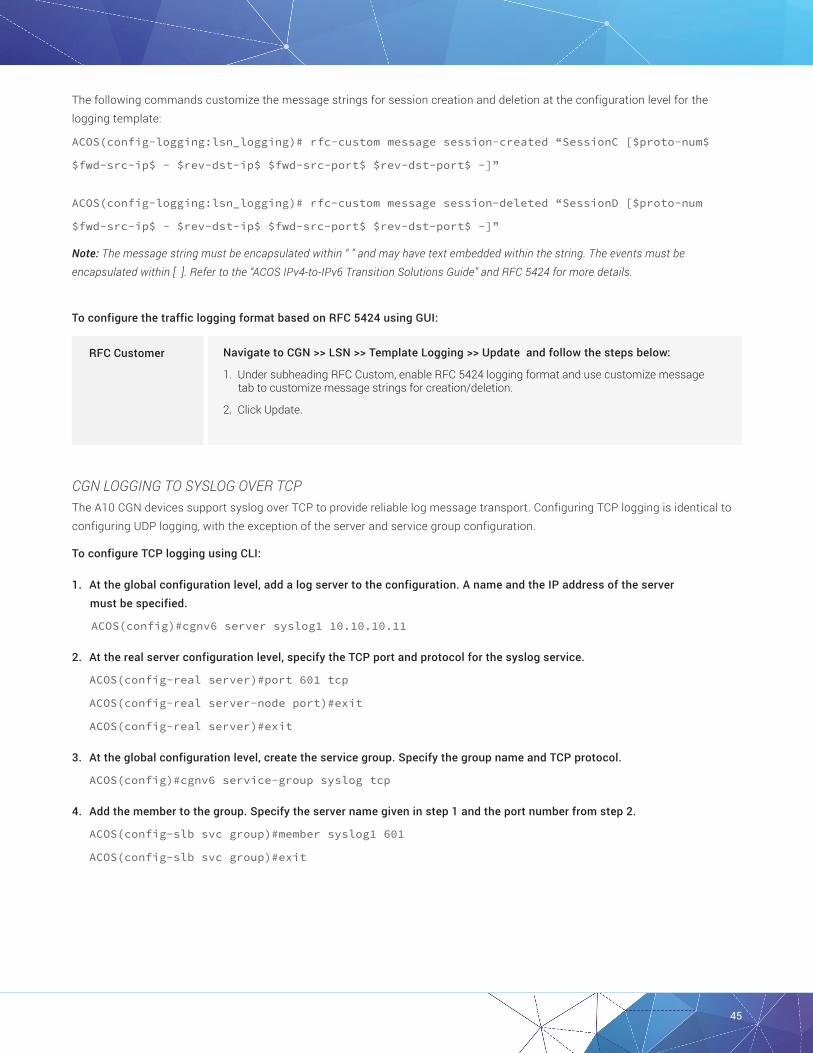
45
The following commands customize the message strings for session creation and deletion at the configuration level for the logging template:
ACOS(config-logging:lsn_logging)# rfc-custom message session-created “SessionC [$proto-num$
$fwd-src-ip$ - $rev-dst-ip$ $fwd-src-port$ $rev-dst-port$ -]”
ACOS(config-logging:lsn_logging)# rfc-custom message session-deleted “SessionD [$proto-num
$fwd-src-ip$ - $rev-dst-ip$ $fwd-src-port$ $rev-dst-port$ -]”
Note: The message string must be encapsulated within “ ” and may have text embedded within the string. The events must be encapsulated within [ ]. Refer to the “ACOS IPv4-to-IPv6 Transition Solutions Guide” and RFC 5424 for more details.
To configure the traffic logging format based on RFC 5424 using GUI:
Navigate to CGN >> LSN >> Template Logging >> Update and follow the steps below:
1. Under subheading RFC Custom, enable RFC 5424 logging format and use customize message tab to customize message strings for creation/deletion.
2. Click Update.
RFC Customer
CGN LOGGING TO SYSLOG OVER TCPThe A10 CGN devices support syslog over TCP to provide reliable log message transport. Configuring TCP logging is identical to configuring UDP logging, with the exception of the server and service group configuration.
To configure TCP logging using CLI:
1. At the global configuration level, add a log server to the configuration. A name and the IP address of the server must be specified.
ACOS(config)#cgnv6 server syslog1 10.10.10.11
2. At the real server configuration level, specify the TCP port and protocol for the syslog service.
ACOS(config-real server)#port 601 tcp
ACOS(config-real server-node port)#exit
ACOS(config-real server)#exit
3. At the global configuration level, create the service group. Specify the group name and TCP protocol.
ACOS(config)#cgnv6 service-group syslog tcp
4. Add the member to the group. Specify the server name given in step 1 and the port number from step 2.
ACOS(config-slb svc group)#member syslog1 601
ACOS(config-slb svc group)#exit

46
5. Create the logging template and specify the syslog server group and the events to log.
ACOS(config)#cgnv6 template logging lsn_logging
ACOS(config-logging:lsn_logging)#log fixed-nat user-ports
ACOS(config-logging:lsn_logging)#log fixed-nat port-mappings
ACOS(config-logging:lsn_logging)#log fixed-nat sessions
ACOS(config-logging:lsn_logging)#service-group syslog
Note: In this example, the service group name is “syslog,” and both CGN events (log sessions) and Fixed-NAT events are logged. Alternatively, logging formats, source port for syslog, and so on, also can be modified at this configuration level. Refer to the “ACOS IPv4-to-IPv6 Transition Solutions Guide” for more information.
6. Activate the template by committing the following command at the global configuration level, and specifying the template name given in step 3.
ACOS(config)#cgnv6 lsn logging default-template lsn_logging
For configuration using GUI, refer to the Logging Configuration section.
CGNAT LOGGING TO RADIUSAll A10 CGN devices support CGN logging to RADIUS. CGN device acts as a RADIUS client and provides identical logging events such as the syslog implementation using RADIUS Accounting-Request messages. CGN logging to RADIUS provides a trusted logging environment and simplifies log message analysis.
Configure CGN logging to RADIUS using CLI:
1. At the global configuration level, add a log server to the configuration. A name and the IP address of the server must be specified.
ACOS(config)#cgnv6 server radius1 100.64.100.1
2. At the config-real server configuration level, specify the RADIUS UDP port and protocol for the syslog service.
ACOS(config-real server)#port 1813 udp
ACOS(config-real server-node port)#exit
3. At the global configuration level, create the service group. Specify the group name and TCP protocol.
ACOS(config)#cgnv6 service-group radiusgrp udp
4. Add the member to the group. Specify the server name and UDP protocol.
ACOS(config-cgnv6 svc group)#member radius1 1813
ACOS(config-cgnv6 svc group)#exit
5. Create the logging template and specify the RADIUS server group, RADIUS secret and the events to log.
ACOS(config)#cgnv6 template logging lsn_logging
ACOS(config-logging:lsn_logging)#log sessions
ACOS(config-logging:lsn_logging)#log-receiver radius secret a10rad
ACOS(config-logging:lsn_logging)#service-group syslog
ACOS(config-logging:lsn_logging)#exit
Note: In this example, the service group name is “radiusgp,” the secret is “a10rad,” and CGNAT events (log sessions) are logged. Note that for RADIUS logging, the source-port, format, rfc-custom, facility and severity options do not apply within the configuration context.

47
Verify that there are no packets dropped to server. If the counter is incrementing, verify that at least one RADIUS server is up using the following commands:
ACOS#show cgnv6 log statistics
NAT Logging Statistics:
------------------------------------------------------------------------------------------------------------------------------------------------------------------------------------------
Navigate to CGN >> LSN >> Templates and follow the steps below:
1. Select logging from the drop-down list.
2. Click Create to create a new logging template.
3. Enter lsn_logging as the name for the template in the Name field.
4. Further down the screen, expand the log receiver section.
5. Select the checkbox in the Log Receiver Radius Field.
6. Enter the shared secret in the Secret String field.
7. Click Create.
Radius Logging
TCP Session Created 3745
TCP Session Deleted 3745
TCP Port Allocated 155
TCP Port Freed 0
TCP Port Batch Allocated 0
TCP Port Batch Freed 0
UDP Session Created 0
UDP Session Deleted 0
UDP Port Allocated 0
UDP Port Freed 0
UDP Port Batch Allocated 0
UDP Port Batch Freed 0
ICMP Session Created 649
ICMP Session Deleted 647
ICMP Resource Allocated 649
ICMP Resource Freed 456
ICMPV6 Session Created 0
ICMPV6 Session Deleted 0
ICMPV6 Resource Allocated 0
ICMPV6 Resource Freed 0
GRE Session Created 0
GRE Session Deleted 0
GRE Resource Allocated 0
GRE Resource Freed 0
ESP Session Created 0
ESP Session Deleted 0
ESP Resource Allocated 0
ESP Resource Freed 0
Fixed NAT Inside User Port Mapping 1
Fixed NAT Disabled Configs Logged 0
Fixed NAT Disabled Config Logs Sent 0
Fixed NAT Periodic Config Logs Sent 0
Fixed NAT Periodic Configs Logged 0
Log Packets Sent 0
Log Packets Dropped 2061
TCP Connection Established 0
TCP Connection Lost 0
TCP Port Overloading Allocated 0
TCP Port Overloading Freed 0
UDP Port Overloading Allocated 0
UDP Port Overloading Freed 0
HTTP Request Logged 0
Configure Radius logging using GUI:
6. Activate the template by committing the following command at the global configuration level, specifying the template name given in step 3.
ACOS(config)#cgnv6 lsn logging default-template lsn_logging

48
Verify the configuration using GUI:
To verify that there are no packets dropped to server, navigate to CGN >> LSN >> Stats >> Logging.
LOG BATCHINGBy default, CGN device sends multiple log messages per packet to the external logging server. In some cases, a particular syslog implementation may not handle this situation correctly.
For deployments where logging traffic is minimal or proper syslog operation is not occurring, disable log batching at the configuration level for the logging template.
Configure log batching using CLI:
ACOS(config)#cgnv6 template logging lsn_logging
ACOS(config-logging:lsn_logging)#batched-logging-disable
Configure log batching using GUI:
Navigate to CGN >> LSN >> Template Logging >> Update and follow the steps below:
1. Enable or disable batched logging.
2. Click Update.
Log Batching
PRECISION TIME STAMPCGN devices provide a logging option that increases the precision of the log timestamps. By default, log message timestamps are precise to within 1 whole second. With precision timestamps enabled, log message timestamps are precise to within 1/100th of a second. Precision timestamps are supported for CGN logging to both syslog and radius using Binary and Hex formatting.
To enable precision timestamps, use the resolution command at the configuration level for the logging template.
Configure Precision Timestamp using CLI:
ACOS(config)#CGNV6 template logging lsn_logging
ACOS(config-logging:lsn_logging)#resolution 10-milliseconds
Configure Precision Timestamp using GUI:
Navigate to CGN >> LSN >> Template Logging >> Update and follow the steps below:
1. Set Resolution as 10 Milliseconds or as Seconds.
2. Click Update.
Precision Timestamp

49
NAT POOL LOGGING TEMPLATE ASSIGNMENTThe default behavior for CGN logging is to use the default template for all CGNAT pools. Recall that the template controls the following logging attributes:
• NAT logging facility
• Format
• Events to be logged
• Timestamp resolution
• Target server for logging
• Log method (RADIUS, syslog, and so on)
• Source port
Some environments may require the flexibility to enable different logging parameters per NAT pool. Thunder CGN device supports the ability to map an individual NAT pool to a logging template. This allows specific logging attributes to be assigned with more granularities. Every pool that is not specifically assigned to a logging template will use the default template.
To enable this feature, use the following CLI at the global configuration level:
ACOS(config)#cgnv6 lsn logging pool test_pool template lsn_logging

50
CRITICAL DDOS MITIGATION FEATURESThis section describes critical DDoS security features for CGN.
IP ANOMALY FILTERSACOS provides configurable protection against a range of IP packet anomalies. One of the many is IP anomaly filtering, which monitors the incoming traffic to ensure that all protocol headers are formed properly and behaving in accordance with models’ built-in standards and state machines. The filtering process protects CGN device and network elements from attack based upon known packet signatures, and it disrupts network reconnaissance attempts where attackers may use protocol vulnerabilities to gain target information such as operating system type and version.
NETWORK LAYER
ANOMALY CLASS LAYER 3 LAYER 4
Packet Deformaties
Bad IP Header Len
Bad IP Flags
Bad IP TTL
Oversize IP Payload
Bad IP Payload Len
Bad IP Fragment Ofs
Bad IP Checksum
Runt IP Header
IP-Over-IP Tunnel Mismatch
Vxlan Tunnel Bad IP Length
Nvgre Tunnel Bad IP Length
IP-Over-IP Tunnel Bad IP Length
TCP Bad Urgent Ofs
TCP Short Header
TCP Bad IP Length
TCP Null Flags
TCP Null Scan
TCP Syn & Fin
TCP XMAS Flags
TCP XMAS Scan
TCP Syn Fragment
TCP Fragmented HDR
TCP Bad Checksum
TCP Option Error
Runt TCP/UDP Header
UDP Short Header
UDP Bad Length
UDP Port Loopback
UDP Bad Checksum
Security Attacks
LAND Aattack
Empty Fragment
Micro Fragment
IPv4 Options IP Fragment
No IP Payload
ICMP Ping of Death
TCP Null Flags
TCP Null Scan
TCP XMAS Flags
TCP XMAS Scan
TCP Syn & Fin
TCP Syn Fragment
TCP Fragmented HDR
UDP Kerberos Frag
UDP Port Loopback
Table 1: IP Anomalies that can be detected and dropped.
To configure IP anomaly detection, use the IP anomaly-drop command at the global configuration prompt.

51
The CLI syntax for enabling this feature is:
[no] ip anomaly-drop packet-deformity layer-3
[no] ip anomaly-drop packet-deformity layer-4
[no] ip anomaly-drop security-attack layer-3
[no] ip anomaly-drop security-attack layer-4
Configure IP -Anomaly using CLI:
ACOS(config)#ip anomaly-drop security-attack layer-3
ACOS(config)#ip anomaly-drop security-attack layer-4
These commands enable independent filtering and dropping of Layer 3 and Layer 4 IP anomalies.
Configure IP -Anomaly using GUI commands:
Navigate to Security >> DDoS Protection and follow the steps below:
1. Enable the type of packets to be dropped by checking or unchecking the box against IP Anomaly drop. For example, enable packet deformity Layer 3 etc.
2. You can also allow drops of bad content, out of sequence packets, etc.
3. Click Update.
IP Anomaly
View the drop statistics using CLI command:
In the following output, packets were sent without SYN flag set. Hence, drops are observed as shown below,
ACOS#show ip anomaly-drop statistics
IP Anomaly Drop Statistics
----------------------------------------------------------------------------------------------------------------------------------------------------------------
TCP Bad IP Length Drop 0
TCP Null Flags Drop 42
TCP Null Scan Drop 0
. . .
Note: IP anomaly is not enabled by default.

52
CONNECTION RATE LIMITINGOne of the most common forms of DDoS attack is the volumetric attack, for example, TCP SYN flooding. These attacks flood servers with a large number of packets, thereby consuming resources with open or half-open sessions. To mitigate these types of volumetric attacks, a connection rate-limit feature can be enabled.
Connection rate limiting sets a maximum number of sessions allowed per source IP. This limits the number of connections a user can attempt to initiate per second and if the per second connection limit is exceeded, no new connections will be made, even if the number of total sessions per IP has not been exceeded.
Note: This feature is applicable on CGNAT, NAT44, NAT64, DS-LITE and 6RD-NAT64.
To configure Connection Rate Limiting, follow the steps below:
1. Create an LSN Limit ID (LID).
2. Configure the connection rate limits desired. The default is no limit.
3. Apply the LSN LID to a class list or NAT pool as desired.
To configure connection rate limiting in the CLI, first create or edit an LSN LID by entering the following command at the global configuration level:
[no] cgnv6 lsn-lid num
The LSN LIDs are identified by a number, ranging from 1 to 1023.
Set a connection rate limit using the following command at the LSN LID configuration level:
[no] conn-rate-limit limit
The default is to have no connection rate limit except for the maximum number of connections allowed, if configured elsewhere. Any value from 1 to 65,535 connections per second are allowed.
The statistics for traffic exceeding the configured connection rate limit can be viewed by entering the following show command in CLI:
show cgnv6 lsn statistics
Configure connection rate limit using CLI:
The following example configures a LSN LID with a connection rate limit of 5 connections per second.
1. First, an LSN NAT pool, which will be bound to the LSN LID, is configured.
ACOS(config)#cgnv6 nat pool CGN_Dynamic 192.0.2.33 192.0.2.46 netmask /28 vrid 1
2. The following commands create the LSN LID and configure the connection rate limit before binding the NAT pool.
ACOS(config)#cgnv6 lsn-lid 1
ACOS(config-lsn lid)#conn-rate-limit 5
ACOS(config-lsn lid)#source-nat-pool CGN_Dynamic
ACOS(config-lsn lid)#exit

53
3. The following command binds the LSN LID to a class list.
ACOS(config)#class-list vm_client_cgn01 ipv4
ACOS(config-class list)#100.64.100.1/32 lsn-lid 1
ACOS(config)#cgnv6 lsn inside source class-list rate-limit
Configure connection rate limit using GUI:
Navigate to CGN >> LSN >> LID >> Update and follow the steps below:
1. Enter the connection rate limiting value in the field (adjacent to Connection Rate Limiting tab).
2. Click Update.
Connection Rate Limit
Use the following CLI to view the overall statistics for any traffic exceeding the configured connection rate limit:
ACOS# show cgnv6 lsn statistics
Traffic statistics for LSN:
---------------------------
...
TCP User-Quota Exceeded 11
Conn Rate User-Quota Exceeded 76209849
No Class-List Match 0
...
The “Conn Rate User-Quota Exceeded” counter signifies the number of exceptions for connection rate setup. If this counter is incrementing, it may indicate an attack from either a client or outside devices exploiting EIF. The “No Class-List Match,” “TCP -Quota Exceeded,” “UDP-Quota Exceeded” and “ICMP-Quota Exceeded” counters should also be monitored for an increment.
To determine which user is causing the attack, monitor the log buffer and full-cone NAT session of the CGN device.
For instance, an IP address with a high number of full-cone NAT sessions (high outbound count) could indicate an outside attack targeting the NAT pool addresses or the client itself by exploiting the EIF behavior. To view the full-cone NAT sessions on your CGN device, enter the following command:
ACOS# show cgnv6 lsn full-cone-sessions
LSN Full-cone Sessions:
Prot Inside Address NAT Address Outbnd Inbnd Pool CPU Age Flags
-----------------------------------------------------------------------------------------
TCP 100.64.100.1:45980 192.0.2.33:45980 0 40 CGN_Dynamic 2 - -
Total Full-cone Sessions: 1
Verify the configuration on GUI:
To view the overall statistics for any traffic exceeding the configured connection rate limit:
Navigate to CGN >> LSN >> Stats >> LSN Global.

54
SELECTIVE FILTERING FOR LSNOn selected platforms, ACOS supports selective filtering to identify packets that are incoming at an abnormally fast rate. On enabling this feature, ACOS tracks protocol packets per second rate limits. These limits are then matched on a destination 2-tuple basis (NAT IP and NAT port).
The thresholds are generally not configured for a specific destination 2-tuple. Rather, ACOS creates a destination IP and destination IP port entry in a logging table and tracks this destination 2-tuple of all incoming packets. Packets are dropped when the threshold is exceeded for any given destination 2-tuple.
Note: Entries are programmed into the hardware level on A10 Networks Thunder SPE models (e.g., Thunder 4435 SPE, 5435 SPE, 6435 SPE, 6635 SPE and 14045 SPE). For all other platforms, the entries are programmed into the software level, where thresholds for TCP and UDP traffic can be configured individually, with all Layer 4 traffic subject to the same limit on a per-protocol basis.
LSN selective filtering is performed in two stages:
Stage 1: If the “bad” packets-per-second to a single NAT IP is greater than the configured DDoS protection packets-per-second IP threshold, then processing moves to stage 2.
Stage 2: Processing depends on the protocol:
• TCP/UDP – If “bad” packets-per-second to a single (NAT IP port) pair exceeds the configured threshold, then that pair gets the selective filtering entry. For example, if a TCP packet that hit a NAT IP on port 601 exceeds the threshold, then only TCP packets to port 601 will be blocked. Other TCP packets to that NAT IP will not be affected.
• Other Layer 4 protocols – If “bad” packets-per-second to a single (NAT IP: Layer 4 protocol) pair exceeds the configured threshold, that pair gets an entry
Note: This feature currently is not supported in the GUI.
To configure Layer 4 traffic limits, use the following command on global configuration level:
cgnv6 ddos-protection enable
cgnv6 ddos-protection packets-per-second udp <port>
cgnv6 ddos-protection packets-per-second tcp <port>
cgnv6 ddos-protection packets-per-second other <port>
For example:
ACOS(config)#cgnv6 ddos-protection enable
ACOS(config)#cgnv6 ddos-protection packets-per-second udp 500
ACOS(config)#cgnv6 ddos-protection packets-per-second tcp 500
ACOS(config)#cgnv6 ddos-protection packets-per-second other 300
Configure event logging for DDoS protection at global CLI configuration level:
cgnv6 ddos-protection logging {enable/ disable}

55
For example:
ACOS(config)#cgnv6 ddos-protection logging enable
To verify DDoS protection information:
1. To display IP anomaly filtering statistics, use the following command in CLI:
ACOS# show IP anomaly-drop statistics
IP Anomaly Drop Statistics
--------------------------
...
TCP Bad IP Length Drop 0
TCP Null Flags Drop 64
TCP Null Scan Drop 0
...
2. To display all the blacklisted NAT IP addresses, including normal entries, use the following command on CLI:
ACOS# show cgnv6 ddos-protection entries
Address L4 Port HW? Pkts in last 10 sec
------------------------------------------------------------
192.0.2.35 6 46108 N > 10000
3. To view the overall traffic statistics exceeding the connection rate limit, use the following command on CLI:
ACOS# show cgnv6 lsn statistics
Traffic statistics for LSN:
---------------------------
Total TCP Ports Allocated 2419
Total TCP Ports Freed 2419
Total UDP Ports Allocated 0
Total UDP Ports Freed 0
Total ICMP Ports Allocated 15
Total ICMP Ports Freed 15
Data Session Created 3724
Data Session Freed 3724
User-Quota Created 51
User-Quota Freed 51
User-Quota Creation Failed 0
TCP NAT Port Unavailable 0
UDP NAT Port Unavailable 0
ICMP NAT Port Unavailable 0
New User NAT Resource Unavailable 0
TCP User-Quota Exceeded 1825
UDP User-Quota Exceeded 0
ICMP User-Quota Exceeded 0
Extended User-Quota Matched 0
Extended User-Quota Exceeded 0
Data Session User-Quota Exceeded 0
Conn Rate User-Quota Exceeded 0
TCP Full-cone Session Created 354
TCP Full-cone Session Freed 354
UDP Full-cone Session Created 0
UDP Full-cone Session Freed 0
Full-cone Session Creation Failed 0
Hairpin Session Created 0

56
Self-Hairpinning Drop 0
Endpoint-Independent Mapping Matched 6
Endpoint-Independent Filtering Matched 0
Endpoint-Dependent Filtering Drop 0
Endpoint-Independent Filtering Inbound Limit Exceeded 0
NAT Pool Mismatch Drop 0
TCP Port Overloaded 1284
UDP Port Overloaded 0
TCP Port Overloading Session Created 3349
UDP Port Overloading Session Created 0
TCP Port Overloading Session Freed 3349
UDP Port Overloading Session Freed 0
NAT Pool Unusable 0
HA NAT Pool Unusable 0
No RADIUS Profile Match 0
NAT IP TCP Max Ports Allocated 0
NAT IP UDP Max Ports Allocated 0
No Class-List Match 0
LSN LID Drop 0
LSN LID Pass-through 0
4. To display the logging statistics for selective filtering, enter the following command on CLI. Monitor for drops in the output given below:
ACOS# show cgnv6 ddos-protection statistics
Entry Added 6
Entry Deleted 5
Entry Added to HW 0
Entry Removed From HW 0
HW out of Entries 0
Entry Match Drop 88896010
HW Entry Match Drop 0
SUMMARYThe configuration example in this deployment guide shows how to set up a basic CGN deployment including connectivity to the Internet. A10’s CGN solution has numerous configurable options, some of which are described in the advanced configuration section.
The CGNAT feature set on the Thunder Series provides the following key advantages:
• Transparent NAT connectivity through EIM/EIF
• Interconnectivity through hairpinning
• Fairness and resource sharing
• Comprehensive logging options
• Critical DDoS mitigation features
The Thunder Series provides a feature-rich, powerful and cost-effective platform for implementing Carrier Grade NAT.

57
APPENDIXCGN Example Configuration:
!
vrrp-a common
device-id 1
set-id 1
enable
hello-interval 4
!
system promiscuous-mode
!
class-list vm_client_cgn01 ipv4
100.64.100.1/32 lsn-lid 1
!
ip anomaly-drop packet-deformity layer-3
ip anomaly-drop packet-deformity layer-4
ip anomaly-drop security-attack layer-3
ip anomaly-drop security-attack layer-4
!
vlan 20
tagged trunk 1
router-interface ve 20
name OUTSIDE
!
vlan 30
untagged ethernet 3
router-interface ve 30
name VRRP-LINK
!
vlan 31
tagged trunk 1
router-interface ve 31
name INSIDE
!
hostname ACOS
!
interface management
ip address 10.100.14.56 255.255.255.0
ip control-apps-use-mgmt-port
ip default-gateway 10.100.14.1
enable
!
interface ethernet 1
enable
trunk-group 1 lacp
!
interface ethernet 2
enable
trunk-group 1 lacp
!
interface ethernet 3
enable
!
interface trunk 1
ports-threshold 2 timer 100 do-auto-recovery
!
interface ve 20
enable
ip address 10.200.2.2 255.255.255.0
ip nat outside
!
interface ve 30
enable
ip address 10.200.1.1 255.255.255.0
!
interface ve 31
enable
ip address 100.64.1.2 255.255.255.0
ip nat inside
!
interface loopback 1
ip address 17.17.17.17 255.255.255.255
!
!
vrrp-a vrid 1
floating-ip 10.200.2.1
floating-ip 100.64.1.1
blade-parameters
tracking-options
interface ethernet 3 priority-cost 40

58
!
vrrp-a interface ethernet 3
!
ip route 0.0.0.0 /0 10.200.2.10
!
ip route 10.2.1.0 /24 10.200.2.10
!
ip route 100.64.100.0 /24 100.64.1.4
!
ip route 100.64.101.0 /24 100.64.1.4
!
ip-list fixed_nat_inside
100.64.101.1
!
ip-list fixed_nat_public
192.0.2.49 to 192.0.2.62
!
cgnv6 server syslog1 10.2.1.3
port 514 udp
!
cgnv6 service-group syslog udp
member syslog1 514
!
cgnv6 template logging fixed_nat
service-group syslog
!
cgnv6 template logging lsn_logging
resolution 10-milliseconds
log fixed-nat port-mappings both
log fixed-nat sessions
log fixed-nat user-ports
log port-mappings creation
log sessions
service-group syslog
!
cgnv6 ddos-protection packets-per-second ip 5
cgnv6 ddos-protection packets-per-second other 500
cgnv6 ddos-protection packets-per-second tcp 500
!
cgnv6 lsn endpoint-independent-mapping tcp
port 1 to 500
!
cgnv6 lsn endpoint-independent-filtering tcp
port 1 to 500
!
cgnv6 lsn inside source class-list vm_client_cgn01
!
cgnv6 nat pool CGN_Dynamic 192.0.2.33 192.0.2.46 netmask /28 vrid 1
!
cgnv6 lsn half-close-timeout 3
cgnv6 lsn port-batching size 256
!
cgnv6 lsn-lid 1
source-nat-pool CGN_Dynamic
conn-rate-limit 10
user-quota icmp 100
user-quota udp 1000 reserve 100
user-quota tcp 1000
!
cgnv6 fixed-nat inside ip-list fixed_nat_inside nat ip-list fixed_nat_public vrid 1 ports-per-user 512
!
!
cgnv6 logging nat-resource-exhausted level warning
!
logging monitor debugging
!
router bgp 65000
neighbor 10.200.2.10 remote-as 65000
neighbor 10.200.2.10 update-source 10.200.2.1
redistribute ip-nat route-map nat_redis
!
router ospf 1
default-information originate always route-map default_route
!
route-map default_route permit 1
set ip next-hop 100.64.1.1
!
route-map nat_redis permit 1
set ip next-hop 10.200.2.1
!
end

59
©2017 A10 Networks, Inc. All rights reserved. A10 Networks, the A10 Networks logo, ACOS, Thunder and SSL Insight are trademarks or registered trademarks of A10 Networks, Inc. in the United States and other countries. All other trademarks are property of their respective owners. A10 Networks assumes no responsibility for any inaccuracies in this document. A10 Networks reserves the right to change, modify, transfer, or otherwise revise this publication without notice. For the full list of trademarks, visit: www.a10networks.com/a10-trademarks.
LEARN MORE ABOUT A10 NETWORKS
CONTACT USa10networks.com/contact Part Number: A10-DG-16134-EN-02 AUG 2017
ABOUT A10 NETWORKSA10 Networks (NYSE: ATEN) provides Reliable Security Always™ through a range of high-performance solutions that enable intelligent automation with deep machine learning to ensure business critical applications are protected, reliable and always available. Founded in 2004, A10 Networks is based in San Jose, Calif., and serves customers globally with offices worldwide.
For more information, visit: a10networks.com or tweet @a10Networks