deployment of behind-the-meter energy storage for demand ... · deployment of behind-the-meter...
TRANSCRIPT

NREL is a national laboratory of the U.S. Department of Energy Office of Energy Efficiency & Renewable Energy Operated by the Alliance for Sustainable Energy, LLC This report is available at no cost from the National Renewable Energy Laboratory (NREL) at www.nrel.gov/publications.
Contract No. DE-AC36-08GO28308
Deployment of Behind-The-Meter Energy Storage for Demand Charge Reduction J. Neubauer and M. Simpson
Technical Report NREL/TP-5400-63162 January 2015

NREL is a national laboratory of the U.S. Department of Energy Office of Energy Efficiency & Renewable Energy Operated by the Alliance for Sustainable Energy, LLC This report is available at no cost from the National Renewable Energy Laboratory (NREL) at www.nrel.gov/publications.
Contract No. DE-AC36-08GO28308
National Renewable Energy Laboratory 15013 Denver West Parkway Golden, CO 80401 303-275-3000 • www.nrel.gov
Deployment of Behind-The-Meter Energy Storage for Demand Charge Reduction J. Neubauer and M. Simpson
Prepared under Task No. VTP2.6407
Technical Report NREL/TP-5400-63162 January 2015

NOTICE
This report was prepared as an account of work sponsored by an agency of the United States government. Neither the United States government nor any agency thereof, nor any of their employees, makes any warranty, express or implied, or assumes any legal liability or responsibility for the accuracy, completeness, or usefulness of any information, apparatus, product, or process disclosed, or represents that its use would not infringe privately owned rights. Reference herein to any specific commercial product, process, or service by trade name, trademark, manufacturer, or otherwise does not necessarily constitute or imply its endorsement, recommendation, or favoring by the United States government or any agency thereof. The views and opinions of authors expressed herein do not necessarily state or reflect those of the United States government or any agency thereof.
This report is available at no cost from the National Renewable Energy Laboratory (NREL) at www.nrel.gov/publications.
Available electronically at http://www.osti.gov/scitech
Available for a processing fee to U.S. Department of Energy and its contractors, in paper, from:
U.S. Department of Energy Office of Scientific and Technical Information P.O. Box 62 Oak Ridge, TN 37831-0062 phone: 865.576.8401 fax: 865.576.5728 email: mailto:[email protected]
Available for sale to the public, in paper, from:
U.S. Department of Commerce National Technical Information Service 5285 Port Royal Road Springfield, VA 22161 phone: 800.553.6847 fax: 703.605.6900 email: [email protected] online ordering: http://www.ntis.gov/help/ordermethods.aspx
Cover Photos: (left to right) photo by Pat Corkery, NREL 16416, photo from SunEdison, NREL 17423, photo by Pat Corkery, NREL 16560, photo by Dennis Schroeder, NREL 17613, photo by Dean Armstrong, NREL 17436, photo by Pat Corkery, NREL 17721.
NREL prints on paper that contains recycled content.

iii
This report is available at no cost from the National Renewable Energy Laboratory (NREL) at www.nrel.gov/publications.
Acknowledgment This study was supported by Dave Howell and Brian Cunningham of the Energy Storage, Vehicle Technologies Office, Office of Energy Efficiency and Renewable Energy, U.S. Department of Energy. Special thanks to Kandler Smith and Eric Wood for supporting development of the modeling tools employed herein, Tony Markel for his insight into V2G service, and Ahmad Pesaran for his continual guidance.
iv
This report is available at no cost from the National Renewable Energy Laboratory (NREL) at www.nrel.gov/publications.
List of Acronyms BLAST Battery Lifetime Analysis and Simulation Tool DCM demand charge management GW gigawatt kW kilowatt kWh kilowatt per hour MW megawatt PEV plug-in electric vehicle PV photovoltaic sq. ft. square feet Wh watt-hour

v
This report is available at no cost from the National Renewable Energy Laboratory (NREL) at www.nrel.gov/publications.
Executive Summary Mandates and subsidies for energy storage, including customer-sited, behind-the-meter installations, are on the rise. Where utilities employ demand charge rate structures, the most economic use of energy storage for customers is often to reduce monthly maximum demand. This study identifies how economically motivated customers will use energy storage for demand charge reduction, as well as how this changes in the presence of on-site photovoltaic power generation, to investigate the possible effects of incentivizing increased quantities of behind-the-meter storage. Utilizing historical solar irradiance and demand profiles, we simulate the impact of lithium-ion batteries operated under a peak-shaving control algorithm on electricity costs, then identify cost-optimal battery configurations and their impact on metered load. We find that small, short-duration batteries are most cost-effective regardless of solar power levels, serving to reduce short load spikes on the order of 2.5% of peak demand. While profitable to the customer, such action is unlikely to adequately benefit the utility as may be desired, thus highlighting the need for modified utility rate structures or properly structured incentives.

vi
This report is available at no cost from the National Renewable Energy Laboratory (NREL) at www.nrel.gov/publications.
Table of Contents List of Figures ........................................................................................................................................... vii List of Tables ............................................................................................................................................. vii 1 Introduction ........................................................................................................................................... 1 2 Methods ................................................................................................................................................. 2
2.1 Rate Structure ................................................................................................................................ 2 2.2 Facility Loads ................................................................................................................................ 3 2.3 Photovoltaic Generation ................................................................................................................ 6 2.4 Battery Modeling & Control ......................................................................................................... 7 2.5 Design of Experiments .................................................................................................................. 7
3 Results ................................................................................................................................................... 9 4 Discussion ........................................................................................................................................... 16
4.1 Battery Sizing .............................................................................................................................. 16 4.2 Interaction with PV ..................................................................................................................... 17 4.3 Effect on Energy Consumption ................................................................................................... 17 4.4 Implications for Utilities ............................................................................................................. 17 4.5 Opportunities for Vehicle-to-Grid Service .................................................................................. 18 4.6 Opportunities for Battery Second Use ......................................................................................... 19 4.7 Projecting Potential Market Size ................................................................................................. 19
5 Conclusions ........................................................................................................................................ 20 References ................................................................................................................................................. 21
vii
This report is available at no cost from the National Renewable Energy Laboratory (NREL) at www.nrel.gov/publications.
List of Figures Figure 1. Illustration of the maximum energy storage required for maximum theoretical demand charge
reduction (Emax) in the presence of a perfectly sinusoidal diurnal load profile ........................ 3 Figure 2. Histograms of facility properties ................................................................................................... 4 Figure 3. Distribution of Emax per square foot within sample facilities ........................................................ 5 Figure 4. Facility properties as a function of facility size and type .............................................................. 5 Figure 5. Illustration of the impact of solar intermittency and the noncoincidence of demand and PV
generation on meter load. While the peak PV generation reaches ~160 kW, the peak metered load is reduced by only ~80 kW. ............................................................................................. 6
Figure 6. Normalized PV power production ................................................................................................. 7 Figure 7. Minimum reduction in peak load versus installed battery power for all simulated facilities,
available battery energy, and both with and without PV. ........................................................ 9 Figure 8. Increase in annual energy use versus minimum reduction in maximum monthly meter load for
all simulated cases (both with and without PV) ..................................................................... 10 Figure 9. Impact of battery operation on energy costs and demand charge costs for all simulated cases
(both with and without PV) .................................................................................................... 10 Figure 10. Payback period statistics by stored energy fraction for a 240 minute battery system, no PV
generation. .............................................................................................................................. 11 Figure 11. Payback period statistics by stored energy fraction for a 30 minute battery system, no PV
generation. .............................................................................................................................. 11 Figure 12. Payback period statistics by stored energy fraction for a 240-minute battery system, 50% PV
generation ............................................................................................................................... 12 Figure 13. Payback period statistics by stored energy fraction for a 30-minute battery system, 50% PV
generation ............................................................................................................................... 12 Figure 14. Median payback period across all 98 facilities as a function of battery system energy and
duration .................................................................................................................................. 13 Figure 15. Best system energy and power levels for facilities without PV ................................................ 14 Figure 16. Distribution of payback-period-optimized battery system power levels (no PV) ..................... 14 Figure 17. Distribution of payback-period-optimized battery system energy levels (no PV). ................... 15 Figure 18. Effect of the presence of PV generation on the value of a 0.5% energy scale, 40minute power
scale battery in a DCM role ................................................................................................... 15 Figure 19. Effect of behind-the-meter batteries on aggregated facility loads ............................................. 18
List of Tables Table 1. Southern California Edison’s TOU-GS-2 Option B Rate Structure [6] .......................................... 2 Table 2. Southern California Edison’s TOU-GS-2 Option B Time Periods [7] ........................................... 3 Table 3. Energy and Power Ratings of Battery Systems .............................................................................. 8

1
1 Introduction Over the past few years, mandates and incentives for energy storage have increased dramatically. For example, in 2010 the California legislature passed Assembly Bill 2514 that resulted in the California Public Utilities Commission releasing a procurement target for 1.3 gigawatts (GW) of energy storage in the state by 2020 [1]. Approximately 15% of this allotment has been planned for customer-sited, behind-the-meter storage [2]. Customer-sited storage has been encouraged in California by the self-generation incentive program, which offers up to $1.62 per watt installed [3]. In New York, ConEdison offers up to $2.10 per watt installed for advanced batteries through an enhanced load reduction program [4].
Such incentives can make energy storage attractive to some customers; however, as they are often capped at some percentage of total installed cost, customers must have a viable value stream from the use of this storage to make the venture economically viable. Reduction of facility demand charges—a fee proportional to peak power rather than total energy—is a commonly referenced means to provide that value. In some instances, demand charges can constitute more than 50% of a commercial customer’s monthly electricity cost. While installation of behind-the-meter solar power generation decreases energy costs, solar intermittency due to cloud cover may cause the peak load—and thereby demand charges—to remain unaffected. This then makes demand charges an even larger fraction of the remaining electricity costs. Adding controllable behind-the-meter energy storage, however, can more predictably manage building peak demand, in turn reducing electricity costs.
Optimizing the size and operation of an energy storage system providing demand charge management (DCM) service is important to yield a positive return on investment, even with incentives. The peak demand reduction achievable with an energy storage system depends heavily on the shape of a facility’s load profile, so the optimal configuration will be specific to both the customer and the amount of installed solar power capacity. The sensitivity of DCM value to the power and energy levels of installed solar power and energy storage systems is explored using the National Renewable Energy Laboratory’s Battery Lifetime Analysis and Simulation Tool (BLAST). BLAST is an optimal peak load reduction control algorithm for energy storage systems [5] and can be applied to historic solar power data and meter load data from multiple facilities for a broad range of energy storage system configurations. For each of these scenarios, the peak load reduction and electricity cost savings are computed. From the results, favorable energy storage system configurations are identified that maximize return on investment via minimizing the payback period. Subsequently, the impact of operating such a system on the aggregate meter load seen by the utility is assessed and compared to the objectives of utilities, and the need for properly structured incentives and modified rate structures to better meet those objectives is discussed.

2
This report is available at no cost from the National Renewable Energy Laboratory (NREL) at www.nrel.gov/publications.
2 Methods BLAST is a custom software package created in MATLAB to simulate the response of a battery installed behind-the-meter at a facility operated under various control strategies. Details on the full capability and functionality of the tool can be found in [5]. Within this study, we employ BLAST to explore the performance of batteries in a peak load reduction role in the presence of on-site photovoltaic (PV) generation. Herein PV generation is synthesized from solar irradiance data, then aggregated with historical demand data to create minute-by-minute meter load data, then applied to an equivalent circuit battery model and optimal peak shaving control algorithm to calculate the impact of energy storage on net meter load over a 12-month period. A real-world utility rate structure is then applied to the simulated total meter load to calculate annual electricity costs. Several facilities, each with varying sizes of PV power generation and energy storage systems, are simulated and compared to assess the economic benefit of such technology.
2.1 Rate Structure After reviewing several utility rate structures with demand charge features, we ultimately elected to employ Southern California Edison’s TOU-GS-2 option B rate structure circa April 2013 [6, 7]. While this rate structure is not directly relevant to all of the facilities studied here (due to their size or geographic location), we have selected it for two main reasons: (1) its format is similar to many other demand charge rate structures via inclusion of continuously active facility demand charges and additional time-sensitive demand charges, and (2) the peak demands on record are reset at the end of each month (i.e., it uses a monthly ratchet). The relevant details of this structure are reproduced in Tables 1 and 2.
Table 1. Southern California Edison’s TOU-GS-2 Option B Rate Structure [6]
Charge Time Cost Facility-related demand charge All $13.94/kW Time-related demand charge Summer on-peak $16.20/kW Summer mid-peak $ 4.95/kW Summer off-peak $ 0.00/kW Time-related energy charge Summer on-peak 14.66 ¢/kWh Summer mid-peak 8.95 ¢/kWh Summer off-peak 5.82 ¢/kWh Winter on-peak 8.59 ¢/kWh Winter mid-peak 8.59 ¢/kWh Winter off-peak 5.47 ¢/kWh

3
This report is available at no cost from the National Renewable Energy Laboratory (NREL) at www.nrel.gov/publications.
Table 2. Southern California Edison’s TOU-GS-2 Option B Time Periods [7]
Summer months 12:00 a.m. June 1 to 12:00 a.m. October 1 Summer on-peak Noon to 6:00 pm Summer mid peak 8:00 a.m. to noon; 6:00 p.m. to 11:00 p.m. Summer off-peak 11:00 p.m. to 8:00 a.m. Winter months 12:00 a.m. October 1 to 12:00 a.m. June 1 Winter on-peak n/a Winter mid peak 8:00 a.m. to 9:00 p.m. Winter off-peak 9:00 p.m. to 8:00 a.m.
2.2 Facility Loads Load data were acquired freely from EnerNOC’s online database for 98 commercial facilities [8]. These data provide demand information over a continuous 12-month period in 5-minute increments, suitable for calculating annual electricity costs where demand charges are calculated for peak demand over a 15-minute period. Inspection of the data and conversation with an EnerNOC representative suggest that the data are purely demand—no PV power generation is included within this data.
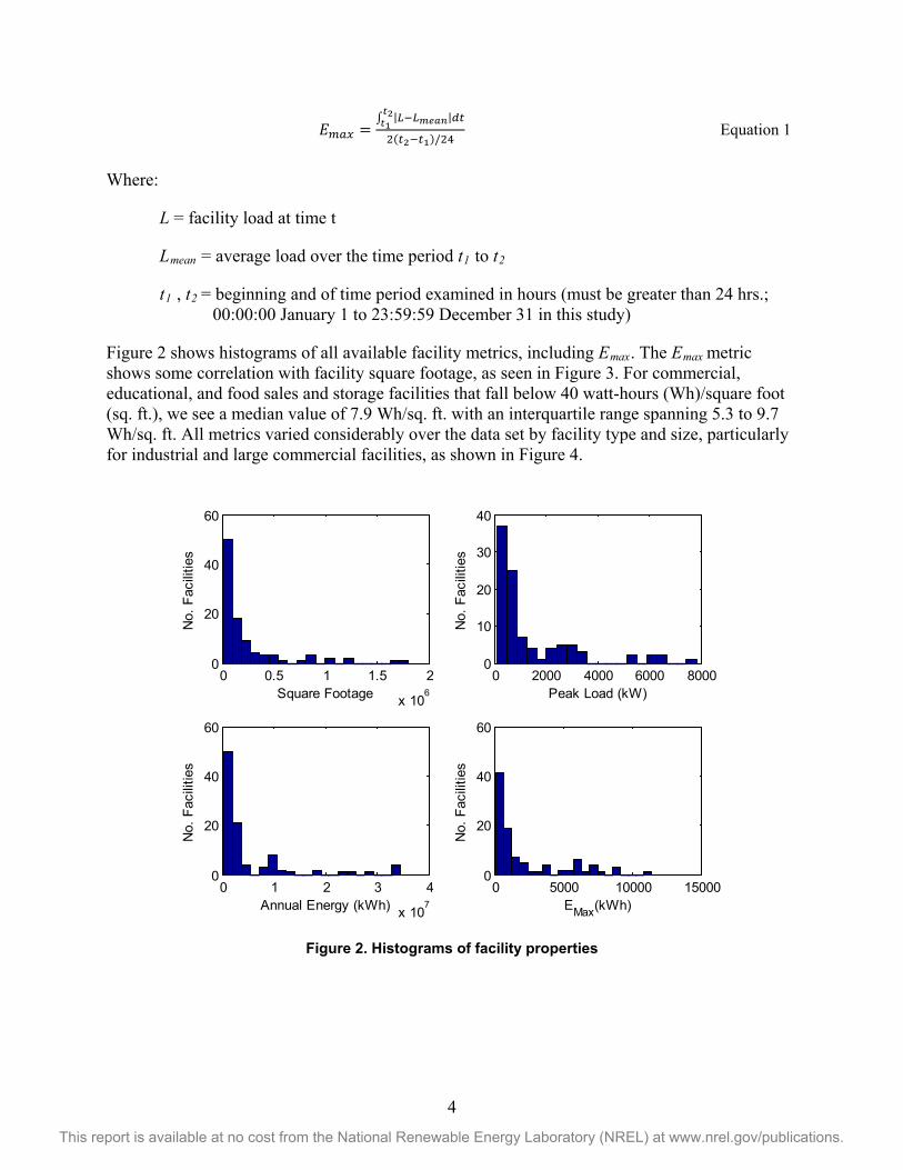
Along with the raw load data, information on the site location, facility square footage, and the nature of operations is also included. In addition to these metrics, a maximum energy storage value, Emax, was created specifically to capture the daily variability in a facility’s load profile by approximating the amount of energy storage required of a perfectly efficient battery to fully flatten the meter load (see Figure 1). If a consistent diurnal load cycle is assumed, then calculation of Emax per Equation 1 yields the theoretical largest energy storage unit necessary for maximum demand charge reduction. Although the load profiles of our examined facilities vary day to day, we apply this equation to approximate Emax in favor of more complex approaches.
Figure 1. Illustration of the maximum energy storage required for maximum theoretical demand
charge reduction (Emax) in the presence of a perfectly sinusoidal diurnal load profile
4
This report is available at no cost from the National Renewable Energy Laboratory (NREL) at www.nrel.gov/publications.
𝐸𝑚𝑚𝑚 =∫ |𝐿−𝐿𝑚𝑚𝑚𝑚|𝑑𝑑𝑡2𝑡12(𝑑2−𝑑1)/24
Equation 1
Where:
L = facility load at time t
Lmean = average load over the time period t1 to t2
t1 , t2 = beginning and of time period examined in hours (must be greater than 24 hrs.; 00:00:00 January 1 to 23:59:59 December 31 in this study)
Figure 2 shows histograms of all available facility metrics, including Emax. The Emax metric shows some correlation with facility square footage, as seen in Figure 3. For commercial, educational, and food sales and storage facilities that fall below 40 watt-hours (Wh)/square foot (sq. ft.), we see a median value of 7.9 Wh/sq. ft. with an interquartile range spanning 5.3 to 9.7 Wh/sq. ft. All metrics varied considerably over the data set by facility type and size, particularly for industrial and large commercial facilities, as shown in Figure 4.
Figure 2. Histograms of facility properties
0 0.5 1 1.5 2
x 106
0
20
40
60
No.
Fac
ilitie
s
Square Footage0 2000 4000 6000 8000
0
10
20
30
40
No.
Fac
ilitie
s
Peak Load (kW)
0 1 2 3 4
x 107
0
20
40
60
No.
Fac
ilitie
s
Annual Energy (kWh)0 5000 10000 15000
0
20
40
60
No.
Fac
ilitie
s
EMax(kWh)

5
This report is available at no cost from the National Renewable Energy Laboratory (NREL) at www.nrel.gov/publications.
Figure 3. Distribution of Emax per square foot within sample facilities
Figure 4. Facility properties as a function of facility size and type
0 10 20 30 40 500
5
10
15
No. o
f Fac
ilitie
sEmax per sq. ft.
> 40 Wh/ sq. ft.
103
104
105
106
107
0
2000
4000
6000
8000
Pea
k Lo
ad (k
W)
103
104
105
106
107
0
1
2
3
4x 10
7
Tota
l Ene
rgy
(kW
h)
103
104
105
106
107
0
5000
10000
15000
EM
ax (k
Wh)
Facility Square Footage
CommercialEducationFood Sales & StorageLight Industrial
6
This report is available at no cost from the National Renewable Energy Laboratory (NREL) at www.nrel.gov/publications.
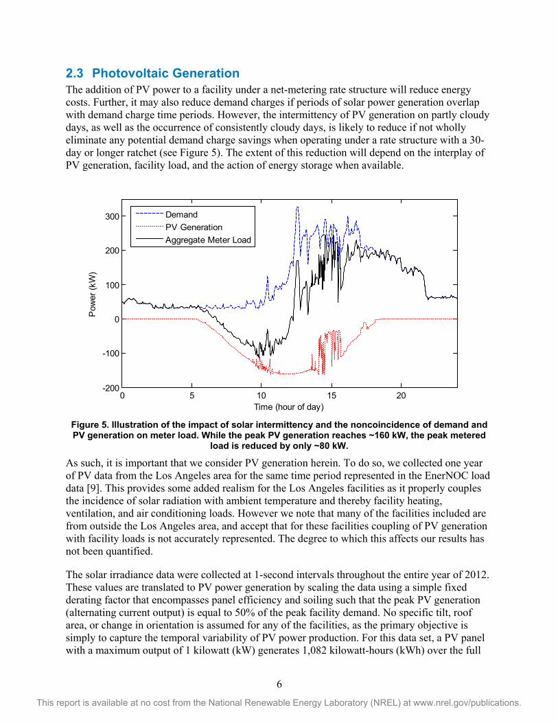
2.3 Photovoltaic Generation The addition of PV power to a facility under a net-metering rate structure will reduce energy costs. Further, it may also reduce demand charges if periods of solar power generation overlap with demand charge time periods. However, the intermittency of PV generation on partly cloudy days, as well as the occurrence of consistently cloudy days, is likely to reduce if not wholly eliminate any potential demand charge savings when operating under a rate structure with a 30-day or longer ratchet (see Figure 5). The extent of this reduction will depend on the interplay of PV generation, facility load, and the action of energy storage when available.
Figure 5. Illustration of the impact of solar intermittency and the noncoincidence of demand and PV generation on meter load. While the peak PV generation reaches ~160 kW, the peak metered
load is reduced by only ~80 kW.
As such, it is important that we consider PV generation herein. To do so, we collected one year of PV data from the Los Angeles area for the same time period represented in the EnerNOC load data [9]. This provides some added realism for the Los Angeles facilities as it properly couples the incidence of solar radiation with ambient temperature and thereby facility heating, ventilation, and air conditioning loads. However we note that many of the facilities included are from outside the Los Angeles area, and accept that for these facilities coupling of PV generation with facility loads is not accurately represented. The degree to which this affects our results has not been quantified.
The solar irradiance data were collected at 1-second intervals throughout the entire year of 2012. These values are translated to PV power generation by scaling the data using a simple fixed derating factor that encompasses panel efficiency and soiling such that the peak PV generation (alternating current output) is equal to 50% of the peak facility demand. No specific tilt, roof area, or change in orientation is assumed for any of the facilities, as the primary objective is simply to capture the temporal variability of PV power production. For this data set, a PV panel with a maximum output of 1 kilowatt (kW) generates 1,082 kilowatt-hours (kWh) over the full
0 5 10 15 20-200
-100
0
100
200
300
Pow
er (k
W)
Time (hour of day)
DemandPV GenerationAggregate Meter Load
7
This report is available at no cost from the National Renewable Energy Laboratory (NREL) at www.nrel.gov/publications.
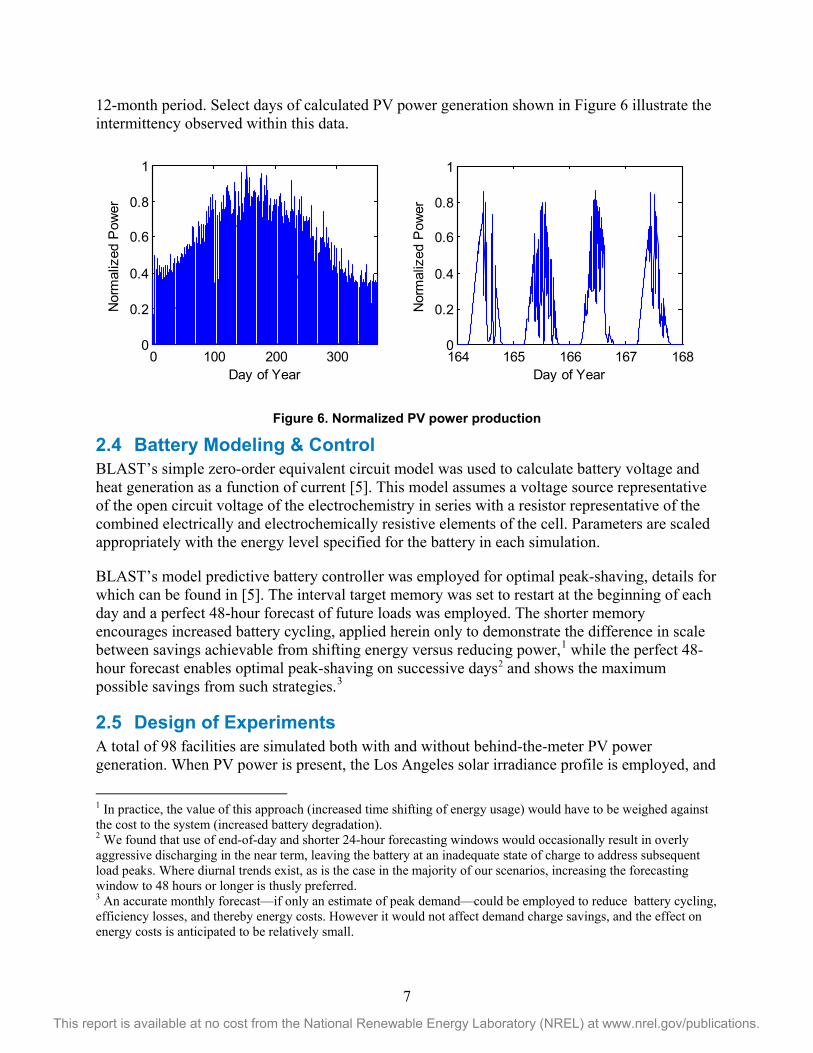
12-month period. Select days of calculated PV power generation shown in Figure 6 illustrate the intermittency observed within this data.
Figure 6. Normalized PV power production
2.4 Battery Modeling & Control BLAST’s simple zero-order equivalent circuit model was used to calculate battery voltage and heat generation as a function of current [5]. This model assumes a voltage source representative of the open circuit voltage of the electrochemistry in series with a resistor representative of the combined electrically and electrochemically resistive elements of the cell. Parameters are scaled appropriately with the energy level specified for the battery in each simulation.
BLAST’s model predictive battery controller was employed for optimal peak-shaving, details for which can be found in [5]. The interval target memory was set to restart at the beginning of each day and a perfect 48-hour forecast of future loads was employed. The shorter memory encourages increased battery cycling, applied herein only to demonstrate the difference in scale between savings achievable from shifting energy versus reducing power,1 while the perfect 48-hour forecast enables optimal peak-shaving on successive days2 and shows the maximum possible savings from such strategies.3
2.5 Design of Experiments A total of 98 facilities are simulated both with and without behind-the-meter PV power generation. When PV power is present, the Los Angeles solar irradiance profile is employed, and
1 In practice, the value of this approach (increased time shifting of energy usage) would have to be weighed against the cost to the system (increased battery degradation). 2 We found that use of end-of-day and shorter 24-hour forecasting windows would occasionally result in overly aggressive discharging in the near term, leaving the battery at an inadequate state of charge to address subsequent load peaks. Where diurnal trends exist, as is the case in the majority of our scenarios, increasing the forecasting window to 48 hours or longer is thusly preferred. 3 An accurate monthly forecast—if only an estimate of peak demand—could be employed to reduce battery cycling, efficiency losses, and thereby energy costs. However it would not affect demand charge savings, and the effect on energy costs is anticipated to be relatively small.
0 100 200 3000
0.2
0.4
0.6
0.8
1
Day of Year
Nor
mal
ized
Pow
er
164 165 166 167 1680
0.2
0.4
0.6
0.8
1
Day of Year
Nor
mal
ized
Pow
er

8
This report is available at no cost from the National Renewable Energy Laboratory (NREL) at www.nrel.gov/publications.
the nameplate PV power is scaled to 50% of the peak facility load. Each of these 196 scenarios is then simulated with 35 different energy storage systems for a total of 6,860 unique cases. The 35 different energy storage systems span seven different energy fractions and five different power ratings (Table 3).
Table 3. Energy and Power Ratings of Battery Systems
Available Energy Fractions 0.5%, 1%, 2%, 3%, 5%, 7%, and 10% of Emax
Power Scale (minimum full available energy discharge duration)
30, 40, 60, 120, and 240 minutes

9
This report is available at no cost from the National Renewable Energy Laboratory (NREL) at www.nrel.gov/publications.
3 Results Figure 7 shows the minimum reduction in the peak load across all facilities, PV installations, and battery energy scaling factors for two system power scales: the 240-minute system and the 30-minute system. The performance of the longest duration system is bounded at an approximately 85% meter reduction to installed battery power ratio, but achieves this metric frequently because it can sustain maximum power for up to 4 hours. The shortest duration system, on the other hand, is bounded by an approximately 60% meter reduction to installed battery power ratio for battery powers less than approximately 25 kW. At higher battery power levels, performance becomes more sensitive to the installed energy fraction and facility load profile, but generally the ratio of meter reduction to installed battery power falls.
Figure 7. Minimum reduction in peak load versus installed battery power for all simulated
facilities, available battery energy, and both with and without PV. The dashed line shows the 1:1 ratio of equal meter load reduction and installed battery power.
Figure 8 shows the increase in annual energy consumption against the minimum reduction in peak load. This increase comes from the imperfect efficiency of the battery. The simulation is in essence a worst-case scenario with respect to energy usage, as the battery is encouraged to cycle each day. Thus, in practice a controller that seeks to minimize battery cycling for the same demand charge reduction would result in much smaller energy use increases.
The increased energy usage and allowance of on-peak charging can lead to increased energy costs, as shown by the cases with positive x-axis values in Figure 9. However, energy costs can also decrease due to the battery discharging mostly during on-peak times and charging mostly during off-peak times. The total number of cases simulated shows a slight bias towards reducing energy costs in this manner. However, in all cases, the economic savings of demand charges dwarf the impact on energy costs, often by an order of magnitude or more.
0 500 1000 1500 2000 2500 30000
50
100
150
200
250
300
Battery Power (kW)
Min
imum
Red
uctio
n in
Pea
k Lo
ad (k
W)
240 min system30 min system

10
This report is available at no cost from the National Renewable Energy Laboratory (NREL) at www.nrel.gov/publications.
Figure 8. Increase in annual energy use versus minimum reduction in maximum monthly meter
load for all simulated cases (both with and without PV)
Figure 9. Impact of battery operation on energy costs and demand charge costs for all simulated
cases (both with and without PV)
Figures 10 and 11 show the simple payback period of the energy storage systems installed in facilities without PV for the longest and shortest system durations, respectively. The cost of the complete installed storage system is assumed to be equal to $300 times the available energy in kilowatt-hours of the system plus $300 times the power in kilowatts of the system. This is intended to represent the cost of both a battery and inverter, where the cost of the battery scales largely with energy and the inverter with power, after the application of any available incentives. The payback period is then calculated as the total system cost divided by the annual utility bill
0 50 100 150 200 250 3000
1
2
3
4
5x 10
4
Minimum Reduction in Peak Load (kW)
Incr
ease
in A
nnua
l Ene
rgy
Use
(kW
h)
-4000 -2000 0 2000 4000-14
-12
-10
-8
-6
-4
-2
0x 10
4
Change in Energy Costs ($)
Cha
nge
in D
eman
d C
harg
e C
osts
($)

11
This report is available at no cost from the National Renewable Energy Laboratory (NREL) at www.nrel.gov/publications.
savings. Discount rates, rate structure evolution, depreciation, and other higher-order effects are explicitly ignored for ease of presentation. The results indicate that shorter system durations and lower energy scaling factors optimize payback.
Figure 10. Payback period statistics by stored energy fraction for a 240 minute battery system, no
PV generation. Each box plot shows the minimum, 25th percentile, median, 75th percentile and maximum payback period across all
98 facilities.
Figure 11. Payback period statistics by stored energy fraction for a 30 minute battery system, no
PV generation. Each box plot shows the minimum, 25th percentile, median, 75th percentile and maximum payback period across all
98 facilities.
0.005 0.01 0.02 0.03 0.05 0.07 0.10
5
10
15
20240 min System
Energy Fraction
Pay
back
Per
iod
(yrs
)
0.005 0.01 0.02 0.03 0.05 0.07 0.10
5
10
15
2030 min System
Energy Fraction
Pay
back
Per
iod
(yrs
)

12
This report is available at no cost from the National Renewable Energy Laboratory (NREL) at www.nrel.gov/publications.
Figures 12 and 13 show payback periods calculated in the same manner for facilities with 50% PV. The results are strikingly similar. In Figure 14, we explicitly compare the cases with and without PV using the median payback period across all 98 facilities. This shows nearly identical trends with respect to absolute payback period and optimal energy storage system sizing.
Figure 12. Payback period statistics by stored energy fraction for a 240-minute battery system,
50% PV generation. Each box plot shows the minimum, 25th percentile, median, 75th percentile and maximum payback period across all
98 facilities.
Figure 13. Payback period statistics by stored energy fraction for a 30-minute battery system, 50%
PV generation. Each box plot shows the minimum, 25th percentile, median, 75th percentile and maximum payback period across all
98 facilities.
0.005 0.01 0.02 0.03 0.05 0.07 0.10
5
10
15
20240 min System
Energy Fraction
Pay
back
Per
iod
(yrs
)
0.005 0.01 0.02 0.03 0.05 0.07 0.10
5
10
15
2030 min System
Energy Fraction
Pay
back
Per
iod
(yrs
)
13
This report is available at no cost from the National Renewable Energy Laboratory (NREL) at www.nrel.gov/publications.
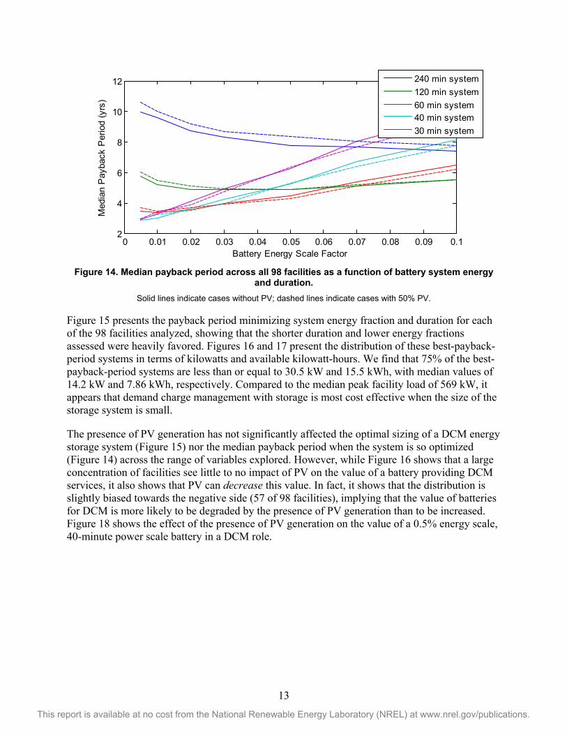
Figure 14. Median payback period across all 98 facilities as a function of battery system energy
and duration. Solid lines indicate cases without PV; dashed lines indicate cases with 50% PV.
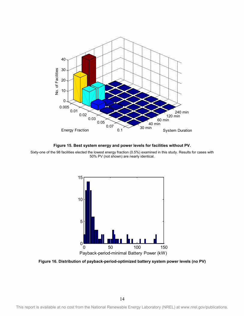
Figure 15 presents the payback period minimizing system energy fraction and duration for each of the 98 facilities analyzed, showing that the shorter duration and lower energy fractions assessed were heavily favored. Figures 16 and 17 present the distribution of these best-payback-period systems in terms of kilowatts and available kilowatt-hours. We find that 75% of the best-payback-period systems are less than or equal to 30.5 kW and 15.5 kWh, with median values of 14.2 kW and 7.86 kWh, respectively. Compared to the median peak facility load of 569 kW, it appears that demand charge management with storage is most cost effective when the size of the storage system is small.
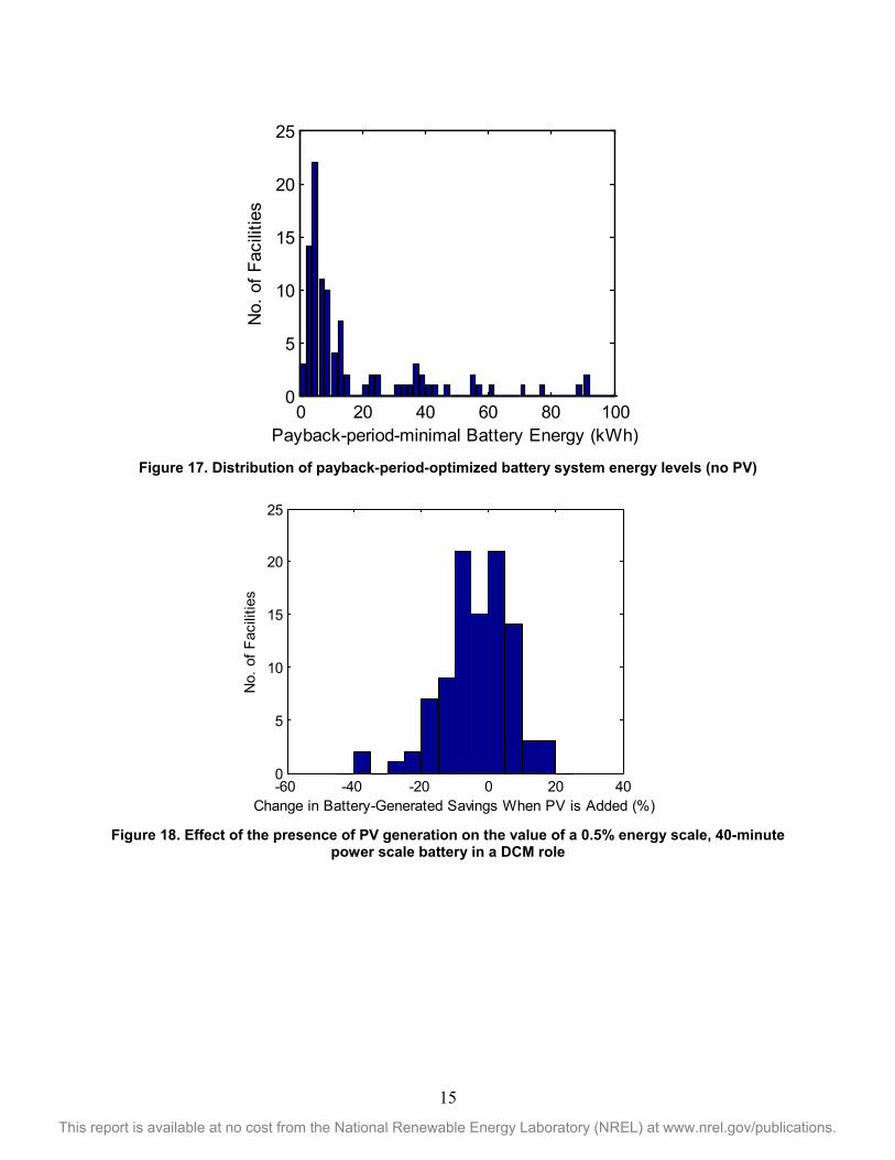
The presence of PV generation has not significantly affected the optimal sizing of a DCM energy storage system (Figure 15) nor the median payback period when the system is so optimized (Figure 14) across the range of variables explored. However, while Figure 16 shows that a large concentration of facilities see little to no impact of PV on the value of a battery providing DCM services, it also shows that PV can decrease this value. In fact, it shows that the distribution is slightly biased towards the negative side (57 of 98 facilities), implying that the value of batteries for DCM is more likely to be degraded by the presence of PV generation than to be increased. Figure 18 shows the effect of the presence of PV generation on the value of a 0.5% energy scale, 40-minute power scale battery in a DCM role.
0 0.01 0.02 0.03 0.04 0.05 0.06 0.07 0.08 0.09 0.12
4
6
8
10
12
Battery Energy Scale Factor
Med
ian
Pay
back
Per
iod
(yrs
)
240 min system120 min system60 min system40 min system30 min system
14
This report is available at no cost from the National Renewable Energy Laboratory (NREL) at www.nrel.gov/publications.
Figure 15. Best system energy and power levels for facilities without PV.
Sixty-one of the 98 facilities elected the lowest energy fraction (0.5%) examined in this study. Results for cases with 50% PV (not shown) are nearly identical.
Figure 16. Distribution of payback-period-optimized battery system power levels (no PV)
0.0050.01
0.020.03
0.050.07
0.1
240 min120 min
60 min40 min
30 min
0
10
20
30
40
System DurationEnergy Fraction
No.
of F
acili
ties
0 50 100 1500
5
10
15
Payback-period-minimal Battery Power (kW)
15
This report is available at no cost from the National Renewable Energy Laboratory (NREL) at www.nrel.gov/publications.
Figure 17. Distribution of payback-period-optimized battery system energy levels (no PV)
Figure 18. Effect of the presence of PV generation on the value of a 0.5% energy scale, 40-minute
power scale battery in a DCM role
0 20 40 60 80 1000
5
10
15
20
25
Payback-period-minimal Battery Energy (kWh)
No.
of F
acili
ties
-60 -40 -20 0 20 400
5
10
15
20
25
Change in Battery-Generated Savings When PV is Added (%)
No.
of F
acili
ties

16
This report is available at no cost from the National Renewable Energy Laboratory (NREL) at www.nrel.gov/publications.
4 Discussion 4.1 Battery Sizing Our simulations have shown that batteries can effectively reduce peak metered power of real-world facilities. Further, for installed systems costs of $300/Wh and $300/kW, the use of storage batteries results in many encouraging payback periods less than 5 years long, and payback periods less than 3 years long for optimized systems. Thus, where technology and incentives combine to reach this price point, the deployment of energy storage for demand charge management could become rather commonplace.
However, even with 4 hours of energy at a system’s maximum power output (the maximum duration considered here), it should not be expected that the system will reduce the peak interval load at the meter by the full power value of the battery system every month of the year. We find that 85% of the rated system power is a more reasonable expectation when the rated power duration is 4 hours. As system duration is decreased (power to energy ratio is increased), this percentage falls substantially and becomes more sensitive to the nature of the facility’s power demands.
Despite the superior ability of longer duration systems to yield peak power reductions closer to the rated maximum system output power, shorter duration systems are superior where minimizing the payback period is concerned. This is a result of the nature of typical load profiles, where the amount of energy necessary to provide a given reduction in peak load increases nonlinearly with the magnitude of the peak load reduction. For example, reducing peak load by 10 kW from its original value may require only 5 kWh of energy, but reducing peak load by 20 kW from its original value may require 15 kWh of energy: doubling the peak power reduction requires tripling the available energy. Because system cost is proportional to power and energy levels, the total cost of the system increases nonlinearly while its value (reduction in utility bill) only increases linearly, and the payback period increases. Minimizing payback thereby drives systems to higher power-to-energy ratios that operate at lower values of absolute facility peak load reduction. While the higher relative variability in facility load profiles at these power levels decreases the ability of the system to consistently reduce peak meter loads by the maximum system power, the economic impact of this phenomenon is secondary in nature to that described above.
Optimizing battery system parameters for payback period therefore results in selection of both the smallest duration and energy values considered here (durations of 30 and 40 minutes, energy fractions of 2% and smaller). The resultant power and energy ratings of the optimum system exhibit sound correlation with the Emax metric; however, the limits of this specific parametric study could have influenced the trend, i.e., optimum system configurations were found at the minimum power and duration metrics examined in this study.
However, while these small systems are shown to result in optimal payback periods, the absolute economic savings may not be a sufficient incentive for facility owners and operators to install such hardware. In practice, it may prove more common that larger energy storage units are installed, trading longer payback periods for larger absolute savings. Fortunately, Figures 10–15 suggest that many facilities can significantly increase battery energy above the optimal values identified herein with only small increases in payback period. Installation of larger systems
17
This report is available at no cost from the National Renewable Energy Laboratory (NREL) at www.nrel.gov/publications.
therefore could be of benefit to both the customer and utility. This could also be strongly affected by available incentives, such as [4] which encourage systems with a 2-hour minimum duration at rated power.
4.2 Interaction with PV Interestingly, optimal battery system specification had little to no sensitivity to the level of the installed PV generation. This was found to be true across the entire range of battery power and available energy studied. This is most likely because PV generation has minimal impact on the nature of the aggregate load profile when viewed on the order of an hour or less (where our optimal systems generally operate), and thus has only marginal impact on optimizing system size.
However, the presence of PV generation can affect the value added by a battery. While the addition of energy storage is found to increase total utility bill savings regardless of the presence of PV generation, it appears that adding storage to a facility without PV is likely to be a more valuable venture than adding storage to a facility with PV. The root cause for this is most probably the fact that PV alone can capture some demand charge savings, leaving fewer savings to be harvested by storage. The importance of this effect is debatable, though, as many facilities see little noticeable impact of PV on the value of storage. Further, trends could change significantly when large amounts of PV are installed, backfeeding power through the meter is restricted, and/or financial incentives are offered for pairing storage with PV.
4.3 Effect on Energy Consumption Total consumption is increased due to the inefficiency of the battery system in all cases. However, there is a strong tendency to reduce energy costs because the battery typically discharges to reduce peak loads during on-peak times where energy prices are high and charges during off-peak times when energy prices are low. The magnitude of energy cost effects is much smaller than the effects on demand charges.
4.4 Implications for Utilities The systems that minimize payback period also result in small reductions in facility peak power, on the order of 2.5%. The continuous duration of these reductions is generally one interval: 15 minutes. Encouraging the deployment of such systems may be of limited benefit to the utility. Demand charge rate structures are generally designed to reduce capacity requirements for on-peak generators and reduce or defer investment in transmission and distribution assets However, when employing batteries to effectively smooth load fluctuation of individual facilities with periods on the order of minutes (as our value-optimized systems are prone to do), it is possible that utilities will see little to no effect in the cumulative peak load of multiple facilities upstream, providing little opportunity for the utility to reap costs savings via reduced investment in transmission, distribution, and generation assets. This effect is demonstrated in Figure 19, showing how the approximately 2.5% reductions in peak load at the individual facility level translates to only approximate 1.5% reduction in peak load when all 98 facilities are aggregated.

18
This report is available at no cost from the National Renewable Energy Laboratory (NREL) at www.nrel.gov/publications.
Figure 19. Effect of behind-the-meter batteries on aggregated facility loads
Encouraging installation of larger systems that result in larger decreases in the peak loads of individual facilities could address this matter. It may also be in the interest of facility owners and operators—while the smaller, short-duration systems minimize the payback period, the smaller utility bill savings may not be viewed to be worth the effort. Incentive programs that enforce a maximum power-to-energy ratio of 1:1, resulting in minimum durations of 1 hour, would be one option for achieving such an end.
4.5 Opportunities for Vehicle-to-Grid Service On the other hand, identification of high power-to-energy ratios as economically optimal is encouraging for the use of plug-in electric vehicles (PEVs) and bi-directional charging infrastructure for demand charge reduction. This is particularly relevant for workplaces considering the addition of chargers for their employees: access to chargers could provide considerable benefit for select plug-in electric vehicle (PEV) drivers [10], while access to battery capacity in the PEVs could offer a more cost-effective approach to demand charge reduction than the installation of dedicated batteries to facility operators. One major concern in this space is the amount of energy that would be depleted from connected vehicles, thus reducing the electric range of the cars for the drivers. This is of most concern for battery electric vehicles that do not have the ability to continue driving once their electric range is exhausted. Our analysis shows, however, that as little as 30 minutes of storage can provide high value to the facility. Thirty minutes on a 93% efficient Level 2 charger (max 6.6 kW alternating current) corresponds to a relatively small 3.5-kWh accessible energy window required from the automobile. If the driver disconnects the vehicle immediately following a 30-minute peak shaving event, approximately 10 miles of range would be lost. Accounting for charger efficiency, replenishing this same amount of range requires approximately 35 minutes. Thus, if a vehicle arrives with more than 10 miles depleted from its maximum range and is parked at a charger for longer than 65 minutes total, it is likely that the vehicle will leave the charger with more energy than it arrived with. This provides value to both the driver and the facility operator. These numbers encourage additional analysis to fully quantify these values, which could in turn encourage policy supportive of deploying bi-directional workplace chargers to both increase penetration of PEVs and decrease emissions for grid electricity.
0 50 100 150 200 250 300 3500
0.005
0.01
0.015
0.02
Day of Year
Red
uctio
n in
15-
min
ute
Ave
rage
Loa
d (fr
ac)

19
This report is available at no cost from the National Renewable Energy Laboratory (NREL) at www.nrel.gov/publications.
In the same light, commercial PEV fleet operators may find considerable benefit from DCM through the use of large commercial PEV storage capacity (on the order of 40 to 80 kWh), either in the context of bi-directional power flow or, more simply, managed charging. Especially for those fleets operated by the same entity as the depot facility manager, utility bill savings can provide common motivation for both parts of their business. Even more, those fleets operating regular routes—as commonly found in several delivery industries—can provide a highly predictable energy storage service, provided the facility peak demands align with periods that the fleet is parked at the depot and either available for discharge (in the case of bi-directional power flow) or charging (in the case of managed charging). The National Renewable Energy Laboratory is presently investigating these opportunities with early commercial fleet PEV adopters.
4.6 Opportunities for Battery Second Use Additionally, the observed distribution of energy and power levels is also advantageous for the second use of PEV batteries, where automotive propulsion batteries are removed from the vehicle at the vehicle’s end of life, repurposed, and deployed in a different application until the end of the battery’s useful life [11]. The small resultant storage systems size—largely less than 15.5 kWh and 30.5 kW—could readily be met by a single repurposed battery electric vehicle battery (typically providing greater than 20 kWh and 90 kW at beginning of life), or even modules there from. This would largely negate the challenges of integrating large energy storage systems from multiple used battery electric vehicle and plug-in hybrid electric vehicle batteries of various states of health, cell or module design, chemistry, etc., and thusly support the low cost of second use batteries projected by [12]. Policies encouraging second use of automotive packs in this way would have similar effects as encouraging vehicle-to-grid, but also delay battery recycling requirements, which provides additional environmental benefits.
4.7 Projecting Potential Market Size Even under a small battery scenario, the total market size for such batteries could be quite large as well. Our observed relation of Emax to facility size (7.9 Wh/sq. ft.) combined with a 40-minute system with a 2% energy fraction yields a coarse rule of thumb of 0.24 watt/sq. ft. and 0.16 Wh/sq. ft. for sizing DCM batteries. Applying this relation to facilities in the United States [13] exclusive of those smaller than 25,000 sq. ft., suggests a market potential of 7,100 megawatt-hours and 10,700 megawatts (MW) of behind-the-meter DCM batteries, assuming all facilities become subject to a demand charge tariff. While our market projection is smaller than a previous Sandia National Laboratories estimate (32,000 MW) due to our assumption of small, payback-period-optimizing batteries, it is still nearly an order of magnitude larger than the much discussed frequency regulation market (1,000 MW) [14]. Such findings may be valuable for current California utilities seeking to find uses for the 1.3 GW of storage they are in the process of procuring [1]—properly deployed and utilized, increased behind-the-meter storage may be an efficient and effective pathway to reaching their target.
20
This report is available at no cost from the National Renewable Energy Laboratory (NREL) at www.nrel.gov/publications.
5 Conclusions Our analysis has shown that small battery systems capable of fully discharging in 30 to 40 minutes offer optimal payback periods of less than 3 years when installed costs reach $300/kW and $300/kWh, respectively. While these price levels may well be lower than what is necessary to purchase suitable hardware today, research and development efforts to reduce battery [15] and inverter costs [16] are aggressively pursuing price points considerably less than our assumed values. Further, the application of utility-provided incentives can strongly reduce net costs to the user [3, 4]. It also appears that use of PEVs for DCM via vehicle-to-grid service may be attractive to both PEV drivers and facility operators as an alternative to dedicated stationary storage. Thus, employing energy storage in one form or another for behind-the-meter DCM may be economically viable for select customers today, and to vastly increasing amounts in the future, ushering in a time where customer-sited DCM energy storage is common place.
It is important to note, however, that this study assumes perfect forecasts for demand and PV generation. Economic sensitivity to forecast errors, while not explored herein, could be high, as such errors could result in commanding too little action from the battery system when meter loads are over predicted, or in running out of battery energy during peak load times when meter loads are under predicted. While conservative use of battery capacity could address forecast error, it will effectively reduce the savings generated by a given system. On the other hand, many commercial facility loads are strongly subject to local weather conditions, which are reasonably predictable, and forecast periods need only be on the order of 48 hours. Thus, the forecasting challenge may likely be surmountable.
While these factors would all suggest future widespread use of energy storage for DCM, it is important to recognize that utility rate structures are subject to change. As more customers begin reducing peak loads with energy storage and other methods, it is possible that the price per kilowatt placed on peak loads by utilities will fall, making use of costly hardware less economically attractive for this task. Competing trends in wind and solar power, distributed generation, and smart-grid technologies make prediction of demand charge trends challenging over the long term. However, where the cost of energy storage is relatively high and payback periods are longer, sensitivity to such fluctuation will increase. Accordingly, policy to stabilize rate structures for customers over the periods of time similar to anticipated payback periods would encourage the use of this technology.

21
This report is available at no cost from the National Renewable Energy Laboratory (NREL) at www.nrel.gov/publications.
References [1] “California Sets Energy Storage Target of 1.3 GW by 2020.” 2013. Greentech Media. Accessed June 18, 2014. http://www.greentechmedia.com/articles/read/california-sets-1.3gw-energy-storage-target-by-2020
[2] “California Proposed First-In-Nation Grid-Scale Energy Storage Targets.” 2013. Berkeley Energy & Resources Collaborative. Accessed June 18, 2014. http://berc.berkeley.edu/california-proposes-first-in-nation-grid-scale-energy-storage-targets/
[3] “About the Self Generation Incentive Program.” California Public Utilities Commission. Accessed June 18, 2014. http://www.cpuc.ca.gov/PUC/energy/DistGen/sgip/aboutsgip.htm
[4] “Enhanced Load Reduction.” ConEdison. Accessed June 18, 2014. http://ny-best.org/sites/default/files/type-page/31348/attachments/ConEdison.pdf
[5] Neubauer, J. Battery Lifetime Analysis and Simulation Tool (BLAST) Documentation. NREL/TP-5400-63246. Golden, CO: National Renewable Energy Laboratory. http://www.nrel.gov/docs/fy15osti/63246.pdf
[6] Cal. PUC Sheet No. 51745-E: Schedule GS-2, General Service – Demand. Effective April 12, 2013. Southern California Edison, Rosemead, CA.
[7] “Business Rate Basics: Rate Schedule TOU-GS-2-B for Medium-Sized Businesses.” Southern California Edison, 2014. Accessed June 16, 2014. https://www.sce.com/wps/wcm/connect/c07b114a-b2a6-4d0e-a097-e9afeb255fa1/Business_2_TOU_Fact_Sheet_OptionB.pdf?MOD=AJPERES
[8] “2012 Commercial Energy Consumption Data.” EnerNOC, 2013. Accessed January 14, 2013. https://open-enernoc-data.s3.amazonaws.com/anon/index.html
[9] “Daily Plots and Raw Data Files.” National Renewable Energy Laboratory. Accessed January 15, 2013. http://www.nrel.gov/midc/lmu/
[10] Neubauer, J.; Wood, E. “The Impact of Range Anxiety and Home, Workplace, and Public Charging Infrastructure on Simulated Battery Electric Vehicle Lifetime Utility.” Journal of Power Sources (257), 2014, pp. 12–20. doi:10.1016/j.jpowsour.2014.01.075
[11] Neubauer, J.; Pesaran, A. “The Ability of Battery Second Use Strategies to Impact Plug-In Electric Vehicle Prices and Serve Utility Energy Storage Applications.” Journal of Power Sources (196:23), 2011, pp. 10351–10358. doi:10.1016/j.jpowsour.2011.06.053
[12] Neubauer, J.; Pesaran, A.; Williams, B.; Ferry, M.; Eyer, J. “A Techno-Economic Analysis of PEV Battery Second Use: Repurposed-Battery Selling Price and Commercial and Industrial End-User Value.” Prepared for 2012 SAE World Congress and Exhibition, April 24–26, 2012. NREL/CP-5400-53799. Golden, CO: National Renewable Energy Laboratory, January 2012; 13 pp. http://www.nrel.gov/docs/fy12osti/53799.pdf
22
This report is available at no cost from the National Renewable Energy Laboratory (NREL) at www.nrel.gov/publications.
[13] “2012 CBECS Preliminary Results.” U.S. Energy Information Administration. Accessed June 23, 2014. http://www.eia.gov/consumption/commercial/reports/2012/preliminary/index.cfm
[14] Eyer, J.; Corey, G. Energy Storage for the Electricity Grid: Benefits and Market Potential Assessment Guide. SAND2010-0815. Albuquerque, NM: Sandia National Laboratories, 2010. http://www.sandia.gov/ess/publications/SAND2010-0815.pdf
[15] “U.S. Battery R&D Progress & Plans.” 2013. U.S. Department of Energy Vehicle Technologies Office. Accessed June 16, 2014. http://energy.gov/sites/prod/files/2014/03/f13/es000_howell_2013_o.pdf
[16] “The Prospect for $1/Watt Electricity from Solar.” U.S. Department of Energy, Office of Energy Efficiency and Renewable Energy, 2010. Accessed June 16, 2014. http://www1.eere.energy.gov/solar/sunshot/pdfs/dpw_lushetsky.pdf