derailment protection and containment for rail underbridges...to direct when or under what...
TRANSCRIPT
Derailment protection and containment for
rail underbridges
Code of Practice
Please note this is a RISSB Code of Practice Draft Document content exists for RISSB product development purposes only and should not be relied upon or considered as final published content.
Any questions in relation to this document or RISSB’s accredited development process should be referred to RISSB.
RISSB Office
Phone:
(07) 3724 0000 Overseas: +61 7 3724 000
Email:
Web:
www.rissb.com.au
Derailment protection and containment for rail underbridges Page 2 of 21
Notice to users The reliance upon or manner of use of this RISSB product is the sole responsibility of the user who is to assess whether it
meets their organisation’s operational environment and risk profile.
Keeping Codes of Practice up-to-date
To maintain their currency, Code of Practice developed by RISSB are periodically reviewed, and new editions published
when required. Between editions, amendments can be issued.
It is important that readers assure themselves of that they are using a current RISSB Code of Practice. Information about
RISSB Codes of Practice amendments, can be found by visiting www.rissb.com.au.
RISSB welcomes suggestions for improvements and asks readers to notify us immediately of any apparent inaccuracies or
ambiguities, please contact us via email at [email protected] or write to Rail Industry Safety and Standards Board, PO Box
518, Spring Hill, QLD 4004, Australia.
RISSB product can be found at: http://www.rissb.com.au/products/.
Document Control
Identification
Document Title Version Date
Derailment protection and containment for rail underbridges Draft for public comment
10 July 2019
Copyright © RISSB
All rights are reserved. No part of this work is to be reproduced or copied in any form or by any means, electronic or
mechanical, including photocopying, without the written permission of RISSB, unless otherwise permitted under the
Copyright Act 1968.
Draft fo
r pub
lic co
mment

Derailment protection and containment for rail underbridges Page 3 of 21
Contents 1 Introduction .................................................................................................................................. 4
Purpose .......................................................................................................................... 4
Focus .............................................................................................................................. 4
Approach ........................................................................................................................ 4
2 Scope ............................................................................................................................................ 5
3 Objective ....................................................................................................................................... 5
4 Derailment protection systems .................................................................................................... 5
5 The bridge system ......................................................................................................................... 5
General ........................................................................................................................... 5
System limits .................................................................................................................. 6
6 System elements........................................................................................................................... 6
Infrastructure ................................................................................................................. 6
Bridge and track interface .............................................................................................. 8
Operating environment ................................................................................................. 9
7 Risk management tools and techniques ....................................................................................... 9
General ........................................................................................................................... 9
Impact of system elements .......................................................................................... 10
Derailment consequences ............................................................................................ 10
Derailment Likelihood .................................................................................................. 11
Controls ........................................................................................................................ 11
Implementation ........................................................................................................... 12
8 Reference documents ................................................................................................................. 12
Appendix A Types of rail underbridges ........................................................................................... 13
Appendix B Types of derailment protection ................................................................................... 15
Appendix C Suitability of protection systems ................................................................................. 19
Appendix D Potential controls ......................................................................................................... 19
Draft fo
r pub
lic co
mment

Derailment protection and containment for rail underbridges Page 4 of 21
1 Introduction
Purpose
The derailment protection for rail underbridges code of practice is intended to address all inputs
required by a bridge designer to meet AS 5100.2017 Part 2 S11 derailment protection. It provides a
method for each rail authority to objectively determine the design inputs from information available for
each railway.
The code of practice provides further information on relevant aspects not specified in AS 5100, including
the end conditions of bridges, transitioning from ballast deck to direct fixed structures and combinations
of design options.
The code of practice also provides guidance on how to demonstrate so far as is reasonably practicable
(SFAIRP) as required and defined by the Rail Safety National Law.
The code of practice addresses how the rail infrastructure maintainer will give due consideration to the
traffic type (freight, passenger, heavy haul, and mixed), priority of protection of the infrastructure,
rolling stock, passengers, crew, bystanders and road users.
Focus
The focus of this code of practice is to provide a method for selecting appropriate derailment protection
systems rather than providing design solutions. It also provides guidance on issues to consider when
assessing the risk of derailment as well as potential control measures.
Approach
For various reasons during the life cycle of a rail underbridge a risk assessment could be conducted to
better understand and manage the hazards arising from that asset. This code of practice does not seek
to direct when or under what circumstances a risk assessment should be undertaken. Rather it describes
a methodology for conducting a risk assessment, following these steps:
• Treat the bridge, its surrounds and the operating environment as a system.
• Identify derailment causal factors within that system.
• Assess the risk from each of these causal factors.
• Determine potential protection measures having regard to the type of bridge and available technology.
• Select measures to implement having regard to the SFAIRP principles.
• Embed protection measures in structure design or operating procedures as appropriate.
Draft fo
r pub
lic co
mment

Derailment protection and containment for rail underbridges Page 5 of 21
2 Scope
This code of practice applies to all rail underbridges. It does not apply to rail overbridges.
For the purpose of this document, a rail underbridge is defined as a bridge supporting rail infrastructure
and spanning a road, waterway or other feature.
3 Objective
The objective of this code of practice is to provide guidance on what type and level of derailment
protection is required so as to ensure the bridge is safe from derailment risk SFAIRP (what the person
concerned knows, or ought to reasonably know).
4 Derailment protection systems
The objectives of a derailment protection and containment system are to:
• reduce the likelihood of derailment occurring due to the bridge in question;
• reduce the consequences of derailment if it occurs;
• keep derailed or derailing bogies/wheels tracking parallel to and in close proximity to the running rails;
• guide a derailed train away from impact with above deck members as it approaches the bridge;
• minimise harm to occupants of a train in the event of derailment; and
• minimise the degree of disproportionate damage to infrastructure by preventing impact with key structural elements.
In addition to the objectives listed above, stakeholders may identify secondary objectives such as to
avoid a derailed train fouling an adjacent track or to protect supporting piers from damage. Designers
should not allow consideration of these secondary objectives to compromise the ability of solutions to
meet the primary objectives as they are outside the scope of this document.
5 The bridge system
General
A rail bridge is part of a larger system that includes infrastructure and the operating environment.
Therefore, the elements of that system provide the contributing or causal factors which should be
considered in a risk assessment. Draf
t for p
ublic
commen
t

Derailment protection and containment for rail underbridges Page 6 of 21
System limits
The total length of the system includes the distance between bridge abutments plus a designated
distance on the approach and departure side of the bridge.
Approach side
On the approach side the designated distance shall be the greater of:
the longest braking distance of rolling stock using that route at maximum permissible speed; or
the length of the longest train permitted to use that route.
Departure side
On the departure side the designated distance shall be the length of the longest train permitted to use
that route.
6 System elements
Infrastructure
The table below identifies a list of infrastructure elements that should be considered in a derailment risk
assessment.
Item Infrastructure element Effect on risk profile
1. Bridge structure and type Rigidity of the bridge structure means the track geometry across the bridge is more likely to be retained over time and therefore reduce the risk of derailment.
Transom top and ballast deck bridges, supported on bridge top flanges (excluding through trusses), are less likely to suffer damage from impact of derailed rolling stock as there are no above rail structural components that can be damaged in this way. However the risk to rail passengers and users of the obstacle being crossed, must also be considered and mitigated, in a derailment event.
Where above rail level structural components are required, such as a through truss, or through girder, they should be protected to mitigate the risk of structural collapse in a derailment scenario. Guardrails alone would generally be insufficient for this purpose. For new bridges, the structural elements above rail should also be designed for appropriate collision loading to mitigate against collapse, such as in concrete U-trough bridges.
The abutments and approaches need to be considered to ensure the transition between bridge and open track is as smooth as possible.
2. Track structure In general, higher track modulus reduces risk of derailment because the track is more rigid and less prone to alignment errors. Refer to section 5.2 for additional guidance on specific factors to be considered during risk assessments.
3. Track layout including curvature and grade
Any change in track geometry can induce unequal forces which can increase the risk of derailment. Derailments are more likely to occur on curved track rather than tangent track.
Draft fo
r pub
lic co
mment

Derailment protection and containment for rail underbridges Page 7 of 21
Item Infrastructure element Effect on risk profile
4 Use of longitudinal restraint with continuous welded rail (CWR)
Track is maintained so there is zero stress in the rail at a temperature defined by the rail authority known as the stress free temperature (SFT). When the rail temperature is above SFT the rail is in compression, when the temperature is less than SFT the rail is in tension.
In CWR a purpose of rail restraint is to reduce the risk of derailment if a rail fracture occurs. In the event of a fracture rail restraint is designed to ensure the broken rail ends remain aligned vertically and laterally. The longitudinal component of rail restraint is to minimize the gap length that occurs due to the fracture if the rail temperature is below SFT. What is uncertain is the maximum length of gap that a wheel can still pass over safely. German standards (DB Ril 820.2040.2) have recommended a maximum gap of 90 mm for standard gauge track.
5. Presence of turnouts and crossings
As one of the most vulnerable parts of the track, turnouts and crossings necessitate a break in the running rail. There are interconnected parts which all need to be installed and maintained correctly.
6. Track condition Track irregularities can increase the risk of derailment due to gauge or geometry deviations and track buckles.
7. Signalling system Signals placed near bridges can increase risk of derailment due to train handling errors or acceleration and braking loads transferred to the bridge.
8. Electric traction infrastructure
Overhead masts and wiring present an additional hazard in the event of derailment both through the electrical hazard and the time required for repair.
9. Rolling stock type and condition
If passenger services use that route, the risk exposure of passengers presents higher potential for serious injury or death.
10. Rolling stock payload Rolling stock load can increase risk of derailment if it leads to uneven wheel loading. Poorly restrained loads can have the same outcome or lead to collision with other rolling stock or structures.
11. Third party infrastructure The quantity and type of materials in the surrounding land particularly flammable, biohazardous materials and compressed gases.
12. Presence of level crossings Level crossings present increased risk of derailment due to possibility of collision with road vehicles as well as potential for geometry exceptions and obstructions.
13. Site conditions, including cuttings and embankments
A derailment occurring on an embankment can have increased consequences compared to one occurring on level track.
14. History of incidents and defects at the locality
Some sites such as black soil country have greater potential for derailment without being able to identify root causes. Note that the fact that there has not been a derailment at a particular site does not demonstrate SFAIRP.
15. Proximity to adjacent tracks or structures
Derailment consequences can be greater if there is damage to other rolling stock or structures.
16. Population density of surrounding land
Densely populated land near a derailment site increases the potential for serious injury or death.
17. The presence of services on or near the bridge
Damage to these services can increase consequences of derailment.
Draft fo
r pub
lic co
mment

Derailment protection and containment for rail underbridges Page 8 of 21
Item Infrastructure element Effect on risk profile
particularly gas, electricity, sewerage and communications.
18. Work practices necessary to maintain or repair the track and bridge structure
If not properly controlled and monitored maintenance practices can increase likelihood of derailment due to collision with materials or other obstructions.
Table 6.1 Infrastructure elements to be considered in a derailment risk assessment
Bridge and track interface
The bridge and track interface can influence how derailment can occur. The following table provides
information that should be considered during a risk assessment.
Item Type of Bridge / Track Structure
Factors to be considered in Risk Assessment
1 Transom top The condition and fixity of the sleepers to the main girders will determine the rigidity of this track form / bridge combination. If the main girders are steel and the sleepers are well secured and in good condition, then the system will be stiff and robust.
With timber bridges (which tend to be older structures), the flexibility of the system could be greater, especially if the timber is in poor condition. Sleeper fixity could have deteriorated also leading to greater risk of derailment.
2 Ballast on concrete deck Concrete deck structures tend to be quite rigid, however the depth available for ballast and its age and quality, as well as the use of ballast mats, will determine the remaining track form flexibility. Inadequate depth with the absence of mats will lead to rapid decay of ballast performance and increase the risk of derailment.
3 Ballast on steel deck Steel deck structures are rare in Australia and tend to be less rigid than concrete decks. They also tend to be quite old and take the form of interlinked steel troughs. They require a robust inspection and maintenance regime to ensure continued high performance. Corrosion and loss of ballast being common problems.
As with concrete decks the depth available for ballast and its age and quality will determine the remaining track form flexibility. Again, inadequate ballast depth with the absence of mats will lead to accelerated decay of ballast performance and increase the risk of derailment.
4 Direct fix on concrete This bridge – track structure system tends to be the newest type within the network and is very rigid as well as being very durable with minimum maintenance requirements. This rigidity and durability tends to reduce the likelihood of derailment under normal operating conditions.
5 Direct fix on steel This system is quite rare in Australia and, although very stiff would be considered less rigid than concrete direct fix, primarily due to the greater flexibility of the steel structure in general. It can also be expected that this system will provide a high level of rigidity and durability which tends to reduce the likelihood of derailments, provided an effective inspection and maintenance regime is in place.
Table 6.2 Bridge and track interface information to be considered during a risk assessment
Draft fo
r pub
lic co
mment

Derailment protection and containment for rail underbridges Page 9 of 21
Operating environment
The list of operating elements that should be considered in a derailment risk assessment are listed in the
table below.
Item Operating Element Effect on Risk
1. Operating rules Operating rules are intended to cover the way a railway works and to codify appropriate responses to unforeseen circumstances. How well these are foreseen and dealt with can influence the operational integrity of the railway and therefore the likelihood of derailment.
2. Allowable speed Higher track speed means consequences are greater if a derailment occurs because there is more energy to be dissipated.
3. Potential for over speed events
There could be sections of track where trains are more likely to experience speed overruns. Typically, these are at the bottom of long descending grades.
4. Train handling practices Severe and sudden braking can cause a train to compress leading to override or derailment, while heavy accelerations can cause stretching and possible parting.
5. Maintenance practices Maintenance practices of both the infrastructure and the rolling stock are important. If inspection schedules are not timely and comprehensive it is possible that defects can develop without being detected.
6. Future usage and growth in patronage
As a long-term asset, it is possible that the traffic usage pattern will change over its lifetime. Increased usage increases the likelihood of derailment while increases in train payload increases the consequences of a derailment.
Table 6.3 Operating elements to be considered in a derailment risk assessment
7 Risk management tools and techniques
General
A risk management process is a systematic method of making a structure or operation as safe as
possible. The method has the following steps:
• Identify hazards.
• Assess the likelihood and severity of risks arising from those hazards.
• Eliminate or minimise the risk by implementing controls.
• Review the effectiveness of the controls.
A risk assessment requires the designer to consider the consequences of someone being exposed to a
hazard and the likelihood of it happening. It is intended to make sure appropriate resources are applied
to eliminating or reducing hazards.
The risks identified during an assessment should be comprehensively examined to identify causal
relationships. This will assist in identifying suitable controls and preventive measures.
Draft fo
r pub
lic co
mment

Derailment protection and containment for rail underbridges Page 10 of 21
A risk assessment is an objective exercise. It requires participants with the necessary skills and
experience to make informed decisions about the situation and to justify those decisions.
Risk management systems and procedures should follow the principles described in the latest version of
ISO 31000 risk management and be carried out by competent persons.
Refer to the Office of National Rail Safety Regulator’s guideline - meaning of duty to ensure safety so far
as is reasonably practicable – SFAIRP for additional guidance on the interpretation and application of the
term SFAIRP.
Impact of system elements
Any individual system element as detailed in Section 6 could affect:
• the likelihood of a derailment;
• the consequences of a derailment; and
• both the likelihood and consequences of a derailment.
Derailment consequences
Approach
The risk assessment process requires some allocation of outcome severity and it is important to the
integrity of the process that the allocation be realistic and justified. While the consequences of a
derailment cannot be accurately predicted, there is documented history of outcomes ranging from near
misses to multiple fatalities.
It is possible that the whole tone of the assessment process could be altered depending on what
severity level is chosen. The severity level in turn could be influenced by the extent of research that is
conducted both across jurisdictions and time frames.
To comply with SFAIRP requirements participants need to inform themselves of the nature of the risk
being assessed. Depending on the level of research undertaken participants could in good faith come up
with different outcome severity rankings. These rankings could be difficult to justify if another entity has
chosen different severity level in similar circumstances. In the interests of consistency, it is therefore
recommended that participants allocate a severity ranking consistent with serious personal injury or
fatality.
Limitation of consequences
So far as is reasonably practicable, all wheels of a derailed train should be contained to an alignment
that will support the vertical load of the train as illustrated in Figure 7-1 below. For narrow bridges
where the running rail will not retain a derailed wheel set to a suitable alignment, guardrails or kerbs
may be used to retain the wheel. AS 5100 Part 2 section 11.5.2 specifies that the load is to be applied as
wheel loads, separated by the track gauge and parallel to the track. A load factor of 1.2 shall be applied
to the design rail traffic load of the bridge. The containment device shall be designed as described in this
code of practice.
Draft fo
r pub
lic co
mment

Derailment protection and containment for rail underbridges Page 11 of 21
Figure 7-1 Design intent of containment system
Derailment Likelihood
Data Sources
To populate risk assessments designers should seek historical data on derailment frequencies, causes
and consequences relevant to the structure being designed. Such data may be available from the Office
of National Rail Safety Regulator, Australian Transport Safety Bureau, international regulatory bodies
and agencies, rail infrastructure managers and rolling stock operators.
Such data sets must be relevant to the design in question and take into account the standard of
infrastructure, rolling stock, operating environment and traffic task. If no relevant data is available, data
may be normalised using applicable indices. The indices which can be used include but are not limited
to:
• gross tonnes per annum (GTPA);
• gross tonne kilometres (GTK);
• passenger kilometres per annum (PKPA).
If detailed historical data is not available, the Australian Transport Safety Bureau (ATSB) Transport Safety
Report (refer section Reference documents8) shows in the order of 150 running line derailments
occurring in Australia per year. While these are average values and lack detail, they nonetheless indicate
that derailments are likely to occur multiple times per year in various jurisdictions.
Controls
For each of the derailment causal factors identified in the risk assessment, controls shall be developed
using the most effective method possible.
In order of decreasing effectiveness, the hierarchy is:
• elimination;
• substitution;
• isolation;
• engineering;
• administrative controls.
See Appendix D for discussion on potential controls.
Draft fo
r pub
lic co
mment
Derailment protection and containment for rail underbridges Page 12 of 21
Implementation
Once a suite of controls is agreed on, they need to be allocated to the responsible party for
implementation. Bridge design modifications need to be included in the design brief and allocated to the
bridge designer. Operational controls should be embedded in the rail transport operator’s safety
management system.
8 Reference documents
• Office of National Rail Safety Regulator. Guideline Meaning of duty to ensure safety so far as is reasonably practicable – SFAIRP Published 5 July 2016.
• ATSB Transport Safety Report, RR-2012-010 Final Australian Rail Safety Occurrence Data, 1 July 2002 to 30 June 2012.
Draft fo
r pub
lic co
mment

Derailment protection and containment for rail underbridges Page 13 of 21
A.1 Through girder
A through girder bridge features the main girders rising above track level as can be seen in the example
in Figure A-1.
Figure A-1 Example of through girder design with structural girders above deck height
A.2 Through truss
A through truss bridge’s primary structural elements such as girders, trusses or suspension cables
extend above bridge deck level as can be seen in Figure A.
Figure A-2: Example of through truss design with truss elements above deck height
Draft fo
r pub
lic co
mment

Derailment protection and containment for rail underbridges Page 14 of 21
A.3 Ballast Deck
A ballast deck bridge’s deck supports ballast, sleepers and rail. Structural members are below deck
height as shown in Figure A-3.
Figure A-3: Example of ballast deck bridge
A.4 Transom Top
A transom top bridge features track directly fixed to the superstructure. Ballast is not provided, and
structural members are below deck as shown in Figure A-4.
Figure A-4.: Example of transom top bridge. Structural members are below deck
Draft fo
r pub
lic co
mment

Derailment protection and containment for rail underbridges Page 15 of 21
B.1 General
Derailment management systems comprise one or more of the devices listed below that should be
designed to act individually, or in combination where compatible, to meet the functional and
performance requirements of the RIM. Derailment management systems should be continuous for the
full extent of the underbridge, including approach slabs, without snag points and without horizontal or
vertical deviations greater than 10 degrees.
B.2 Close containment devices
These are devices designed to retain derailed vehicles in close proximity to the running rails. Examples
include guard rails and integrated track systems that replicate the function of guard rails. They should
only be used to supplement other containment devices listed below in this table on new structures.
A guard rail is a rail (inside or outside the running track) used to restrain lateral movement of a derailed
wheelset. These are used to protect structures or control the lateral movement of the wheelset on
bridges or in other higher risk situations. They are used on underbridges, overbridges, footbridges,
tunnels, miscellaneous structures, track slabs, airspace developments and level crossings.
While guard rails can provide some level of risk mitigation against derailment, there are a number of
issues associated with their use:
• Cost and effort required to maintain the track - the RIM may be able to use tamping machines with guard rails fixed to the sleepers but unable to use ballast regulators. Manual ballast regulation increases maintenance effort and financial cost.
• Effectiveness of guard rails in achieving their design intent.
• Guard rails could increase the consequences in some derailment scenarios. If a train is already derailed when approaching the bridge and strikes the Vee of the guard rail on the wrong side, it is possible that the guard rail could deflect the train further from the track centre, instead of containing it.
• Automatic train protection (ATP) installation issues - section of guard rail to be cut out to accommodate balises.
• A lack of documented justifications for deciding to install and maintain a guard rail at a site or at a category of sites exhibiting the same characteristics.
Close containment devices are likely to be effective in containing low speed, reduced axle load
derailments but are less effective in containing high speed or heavy axle load derailments.
They are generally ineffective in containing derailments that result in jack-knifing of rolling stock
vehicles.
Examples of use are:
• Deutsche Bahn (Germany) generally deploys guard rails on lines with mixed traffic on a risk-based approach; SNCF (France) deploys guard rails on structures and at other high-risk locations;
• SNCB (Belgium) generally deploys guard rails on high embankments and structures;
Draft fo
r pub
lic co
mment

Derailment protection and containment for rail underbridges Page 16 of 21
• Great Belt (Storebælt) Railway Link (Denmark) deploys guard rails on bridges;
• Shinkansen (Japan) generally deploys guard rails on structures and at other high-risk locations;
• NWRL (Sydney) has deployed concrete close containment upstands on the outside of gauge;
• CTD (Melbourne) uses close containment concrete upstands on the inside of gauge with secondary protection provided by derailment kerbs;
• KiwiRail (New Zealand) mandates guard rails on open-deck bridges.
Figure B-1 Example of guard rails
Draft fo
r pub
lic co
mment

Derailment protection and containment for rail underbridges Page 17 of 21
B.3 Derailment kerbs
A derailment kerb is a kerb integrated with the bridge deck and located in accordance with AS5100.2
section 11.5.4 with due regard to rolling stock clearance requirements of the rail transport operator.
Their primary function is to retain derailed rail vehicles on the underbridge deck in close proximity to
the running rails.
Where a conflict exists between derailment kerb height and step height to a position of safety, priority
should be given to the derailment kerb height.
Derailment kerbs are likely to be effective in containing derailments that do not involve secondary
effects such as jack-knifing.
They are generally ineffective in containing derailments that result in jack-knifing of rolling stock
vehicles.
Examples of use are:
• CTRL (UK) installs derailment kerbs are installed at specific high-risk locations;
• CTD, (Melbourne) uses derailment kerbs in conjunction with close containment concrete upstands;
• Øresund Link (Denmark/Sweden) deploys derailment kerbs to protect the bridge truss girders;
• Taiwan High Speed Rail employs Rheda ballast less slabs with derailment kerbs.
Figure B-2 Example of derailment kerb and close containment devices (photograph courtesy of Vossloh) Draft fo
r pub
lic co
mment

Derailment protection and containment for rail underbridges Page 18 of 21
B.4 Impact protection barriers
An impact protection barrier is a barrier designed to protect above-deck critical structural members,
such as through-girders, through-arch members and through-truss members and cable-stay anchorages,
from glancing collisions by derailed rail vehicles within the bridge.
Impact protection barriers are largely effective in protecting infrastructure from impact load of derailed
train subject to qualifications of AS 5100.
They are ineffective in containing derailed trains. They are rigid structures and do not mitigate
derailment damage caused to rolling stock vehicles and passengers.
Refer to figure B-3 for an example of an impact protection barrier being used in conjunction with other
types of derailment protection.
B.5 Deflection walls
A deflection wall is a wall designed to protect above-track critical structural members of through bridges
from head-on collisions from derailed trains. They protect piers and abutments that support rail, road or
pedestrian overbridges from the impact of derailed trains.
They are likely to be effective in containing derailments that do not involve secondary effects such as
jack-knifing.
Figure B-3 Example of derailment kerb, impact protection barrier and deflection wall Draft fo
r pub
lic co
mment
Derailment protection and containment for rail underbridges Page 19 of 21
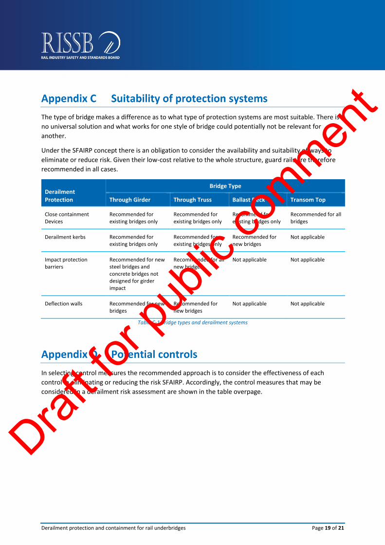
The type of bridge makes a difference as to what type of protection systems are most suitable. There is
no universal solution and what works for one style of bridge could potentially not be relevant for
another.
Under the SFAIRP concept there is an obligation to consider the availability and suitability of ways to
eliminate or reduce risk. Given their low-cost relative to the whole structure, guard rails are therefore
recommended in all cases.
Derailment Protection
Bridge Type
Through Girder Through Truss Ballast Deck Transom Top
Close containment Devices
Recommended for existing bridges only
Recommended for existing bridges only
Recommend for existing bridges only
Recommended for all bridges
Derailment kerbs Recommended for existing bridges only
Recommended for existing bridges only
Recommended for new bridges
Not applicable
Impact protection barriers
Recommended for new steel bridges and concrete bridges not designed for girder impact
Recommended for all new bridges
Not applicable Not applicable
Deflection walls Recommended for new bridges
Recommended for new bridges
Not applicable Not applicable
Table C-1 Bridge types and derailment systems
In selecting control measures the recommended approach is to consider the effectiveness of each
control in eliminating or reducing the risk SFAIRP. Accordingly, the control measures that may be
considered in a derailment risk assessment are shown in the table overpage.
Draft fo
r pub
lic co
mment

Derailment protection and containment for rail underbridges Page 20 of 21
Control level Examples
More
effective
Less
Effective
Eliminate • Remove the bridge.
Substitute • Substitute with an alternative bridge type (i.e. replace a timber bridge with a concrete bridge).
Isolate • Relocation or protection of any hazardous or essential services on the bridge.
Use engineering controls
• For new structures include appropriate derailment protection measures in the design.
• Upgrade track modulus in approaches to bridge.
• Where possible optimise track curvature with curve radii as large as possible in the approaches.
• Design track and signal layouts so that trains maintain steady speed over bridges if possible.
• If turnouts are essential in the bridge approaches enhance their design and maintenance regime.
• Attach guard rails, impact barriers or derailment kerbs.
• Control the gap in the rail that would result from a fracture of the rail on a bridge. Maximum allowable gap 90 mm for standard and wide gauge track, 75 mm for narrow gauge is recommended.
• Install rail on the bridge that is at least the same mass as the rail in adjoining track.
• Ultrasonically test the installation of new rail lengths that are joined by welding prior to installation on the bridge. It is recommended that no weld defects should be allowed.
• Minimise and eliminate where possible, fishplate rail joints on and within 50 m of bridges.
• Locate any rail weld or joint at least 5 m away from a bridge abutment or expansion bearing.
Use administrative controls
• Reduce line speed over any turnout in the approaches to the bridge.
• Enhance maintenance standards in the approaches to the bridge.
• Review maintenance practices for the electrical infrastructure on the bridge.
• Review allowable line speed for different types of rolling stock.
• Install only unused rail on bridges and not rail cascaded from another location on to a bridge.
• Review rolling stock loading practices.
• Enhance inspection and maintenance of any level crossings.
• Review bridge maintenance work practices to reduce the possibility of unintended obstruction.
• Review historical records for relevant incidents and adjust controls accordingly.
• Ensure allowable speed at the site are appropriate compared to other similar sites on the network.
• Review known derailment investigations for speed related causal factors and update controls accordingly.
Table D.1 Potential controls
Draft fo
r pub
lic co
mment
Derailment protection and containment for rail underbridges Page 21 of 21
ABN 58 105 001 465 For information regarding s product developed by RISSB contact: Rail Industry Safety and Standards Board Brisbane Office Level 4, 15 Astor Terrace Brisbane, QLD, 4000 Melbourne Office Level 4, 580 Collins Street, Melbourne, Vic, 3000 PO Box 518 Spring Hill, QLD, 4004 T +61 7 3724 0000 E [email protected]
Draft fo
r pub
lic co
mment