description of rese audio applications and requirements
TRANSCRIPT
Description of ResE Audio Applications and Requirements
Geoffrey M. GarnerSAMSUNG Electronics (Consultant)
IEEE 802.3 ResE SG2005.05.16
SAMSUNG Electronics IEEE 802.3 RESG 2005 Austin 2
Outline
IntroductionDigital audio – backgroundDigital audio interface standardsProperties of digital audio signals at IEC 60958 Interface Backup
More detailed version of presentationReferences
SAMSUNG Electronics IEEE 802.3 RESG 2005 Austin 3
Introduction
This is the second of three related VG presentations1) Description of ResE Video Applications and Requirements2) Description of ResE Audio Applications and Requirements3) Jitter and Wander Requirements for ResE Applications
The backup slides contain a more detailed version of the presentationFor convenience, each presentation contains the complete (i.e., combined) reference list for all three presentations, at the end of the backup slides
SAMSUNG Electronics IEEE 802.3 RESG 2005 Austin 4
Digital Audio – Background
Read CD S/PDIFTransmitter
S/PDIFReceiver
D/AAnalogAudioUnit
AnalogAudioSource
S/PDIFInterface
ClockGenerator
Clock Recovery(Recover datatiming)
Additionalfiltering torecoversampling clock
A/D S/PDIFTransmitter
S/PDIFReceiver
D/AAnalogAudioUnit
S/PDIFInterface
ClockGenerator(Samplingclock)
Clock Recovery(Recover datatiming)
Additionalfiltering torecoversampling clock
SAMSUNG Electronics IEEE 802.3 RESG 2005 Austin 5
Digital Audio – Background (Cont.)
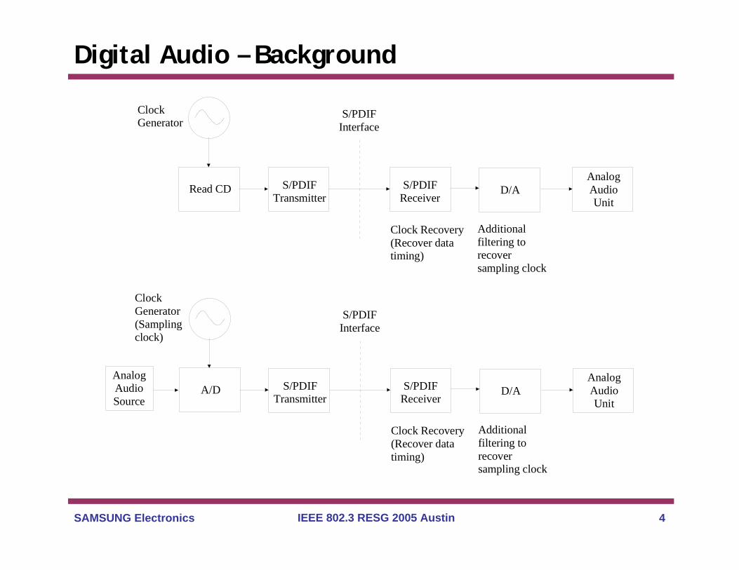
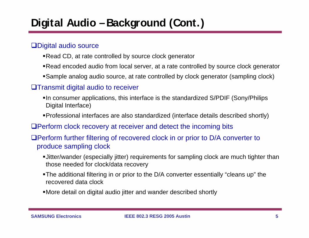
Digital audio sourceRead CD, at rate controlled by source clock generatorRead encoded audio from local server, at a rate controlled by source clock generatorSample analog audio source, at rate controlled by clock generator (sampling clock)
Transmit digital audio to receiverIn consumer applications, this interface is the standardized S/PDIF (Sony/Philips Digital Interface)Professional interfaces are also standardized (interface details described shortly)
Perform clock recovery at receiver and detect the incoming bitsPerform further filtering of recovered clock in or prior to D/A converter to produce sampling clock
Jitter/wander (especially jitter) requirements for sampling clock are much tighter than those needed for clock/data recoveryThe additional filtering in or prior to the D/A converter essentially “cleans up” the recovered data clockMore detail on digital audio jitter and wander described shortly
SAMSUNG Electronics IEEE 802.3 RESG 2005 Austin 6
Digital Audio Interface Standards
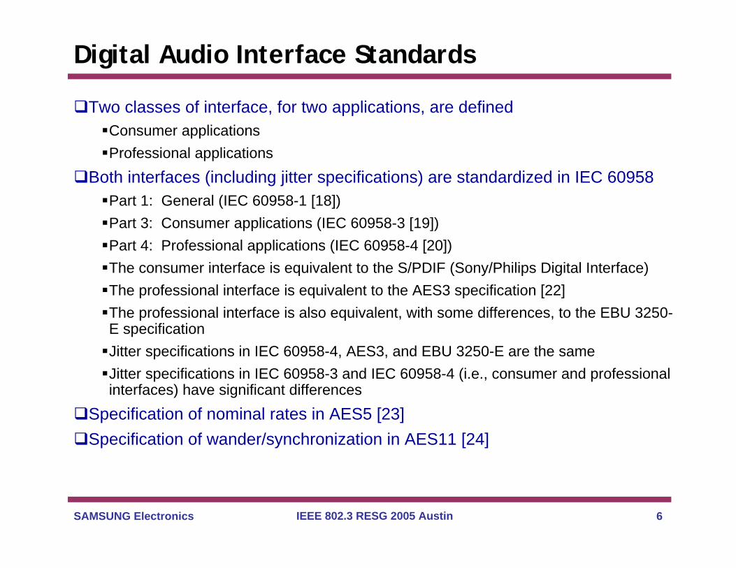
Two classes of interface, for two applications, are definedConsumer applicationsProfessional applications
Both interfaces (including jitter specifications) are standardized in IEC 60958Part 1: General (IEC 60958-1 [18])Part 3: Consumer applications (IEC 60958-3 [19])Part 4: Professional applications (IEC 60958-4 [20])The consumer interface is equivalent to the S/PDIF (Sony/Philips Digital Interface)The professional interface is equivalent to the AES3 specification [22]The professional interface is also equivalent, with some differences, to the EBU 3250-E specificationJitter specifications in IEC 60958-4, AES3, and EBU 3250-E are the sameJitter specifications in IEC 60958-3 and IEC 60958-4 (i.e., consumer and professional interfaces) have significant differences
Specification of nominal rates in AES5 [23]Specification of wander/synchronization in AES11 [24]
SAMSUNG Electronics IEEE 802.3 RESG 2005 Austin 7
Properties of Digital Audio Signal at IEC 60958 Interface
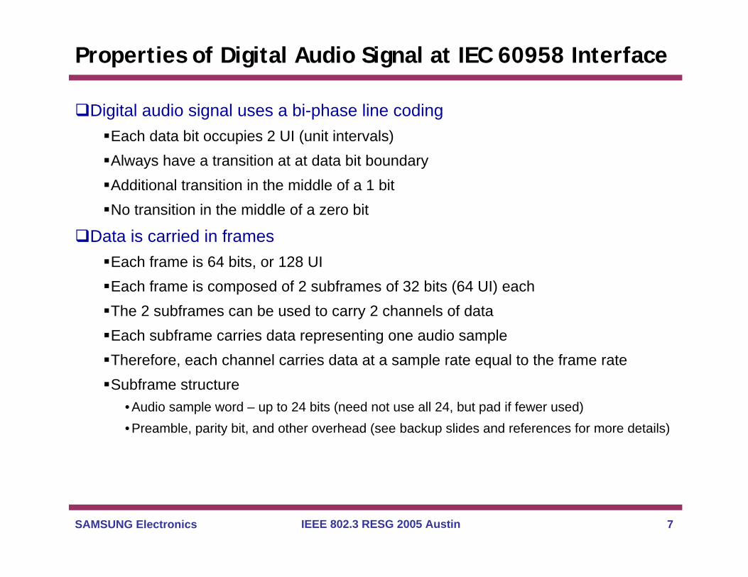
Digital audio signal uses a bi-phase line codingEach data bit occupies 2 UI (unit intervals)Always have a transition at at data bit boundaryAdditional transition in the middle of a 1 bitNo transition in the middle of a zero bit
Data is carried in framesEach frame is 64 bits, or 128 UIEach frame is composed of 2 subframes of 32 bits (64 UI) eachThe 2 subframes can be used to carry 2 channels of dataEach subframe carries data representing one audio sampleTherefore, each channel carries data at a sample rate equal to the frame rateSubframe structure
• Audio sample word – up to 24 bits (need not use all 24, but pad if fewer used)• Preamble, parity bit, and other overhead (see backup slides and references for more details)
SAMSUNG Electronics IEEE 802.3 RESG 2005 Austin 8
Properties of Digital Audio Signal at IEC 60958 Interface
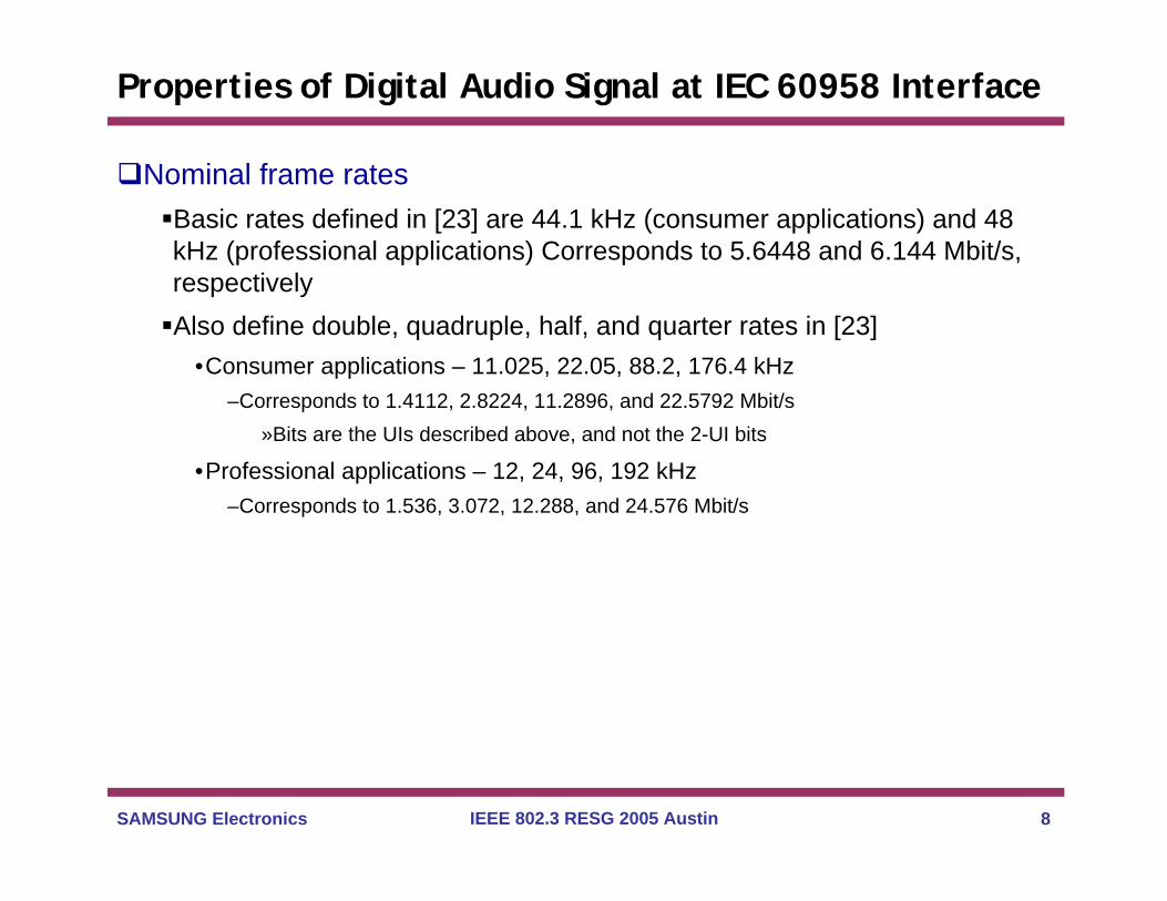
Nominal frame ratesBasic rates defined in [23] are 44.1 kHz (consumer applications) and 48 kHz (professional applications) Corresponds to 5.6448 and 6.144 Mbit/s, respectivelyAlso define double, quadruple, half, and quarter rates in [23]
•Consumer applications – 11.025, 22.05, 88.2, 176.4 kHz–Corresponds to 1.4112, 2.8224, 11.2896, and 22.5792 Mbit/s
»Bits are the UIs described above, and not the 2-UI bits
•Professional applications – 12, 24, 96, 192 kHz–Corresponds to 1.536, 3.072, 12.288, and 24.576 Mbit/s

SAMSUNG Electronics IEEE 802.3 RESG 2005 Austin 9
Properties of Digital Audio Signal at IEC 60958 Interface
Frequency accuracy requirementsThis is the amount the source (sampling) clock is allowed to deviate from nominal, in the long-runNote that the same long-term frequency accuracy requirement applies at all interfaces over sufficiently long time intervals
•This is because bits are not created or destroyed by the network–the long term average rate at which bits cross an interface is the same when the
averaging time is sufficiently long
•Note that frequencies averaged over shorter intervals at various interfaces may have deviations that are larger than the long-term frequency accuracy requirements
–Deviations over shorter time intervals are specified in the form of jitter and Maximum Time Interval Error (MTIE) requirements (see the third VG presentation referred to in the Introduction)
The specified long-term frequency accuracy is also the minimum long-term frequency offset the receiver must tolerate
•A ResE network inserted between the transmitter and receiver must also tolerate this frequency offset
SAMSUNG Electronics IEEE 802.3 RESG 2005 Austin 10
Properties of Digital Audio Signal at IEC 60958 Interface
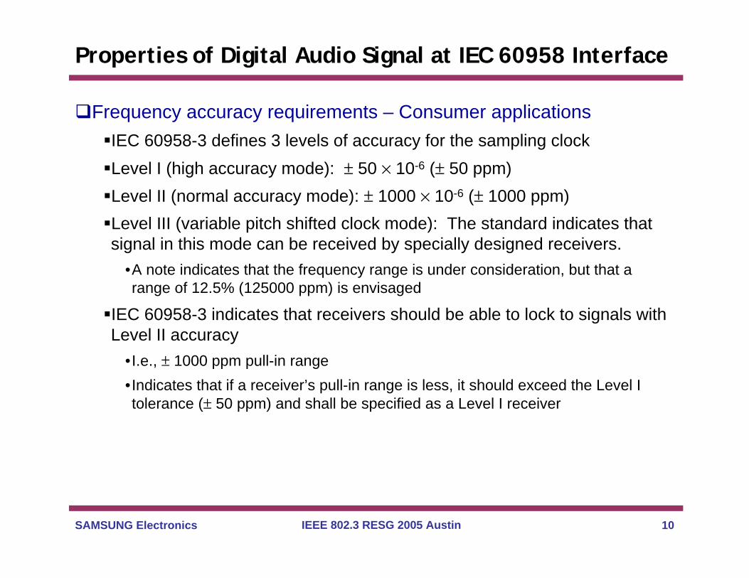
Frequency accuracy requirements – Consumer applicationsIEC 60958-3 defines 3 levels of accuracy for the sampling clockLevel I (high accuracy mode): ± 50 × 10-6 (± 50 ppm)Level II (normal accuracy mode): ± 1000 × 10-6 (± 1000 ppm)Level III (variable pitch shifted clock mode): The standard indicates that signal in this mode can be received by specially designed receivers.
•A note indicates that the frequency range is under consideration, but that a range of 12.5% (125000 ppm) is envisaged
IEC 60958-3 indicates that receivers should be able to lock to signals with Level II accuracy
•I.e., ± 1000 ppm pull-in range•Indicates that if a receiver’s pull-in range is less, it should exceed the Level I tolerance (± 50 ppm) and shall be specified as a Level I receiver

SAMSUNG Electronics IEEE 802.3 RESG 2005 Austin 11
Properties of Digital Audio Signal at IEC 60958 Interface
Frequency accuracy requirements – professional applicationsAES11 specifies 2 levels of frequency tolerance
•Grade 1–frequency tolerance of ± 1 ppm–Pull-in range of ± 2 ppm
•Grade 2–frequency tolerance of ± 10 ppm (note that the ± 10 ppm tolerance is indicated in AES5
also)–Pull-in range of ± 50 ppm
•Equipment designed to provide a Grade 1 signal shall only be required to lock to other Grade 1 signals
AES11 defines the Digital Audio Reference Signal (DARS) for studio applications
•May be used to time all the equipment in a studio–May also time equipment by incoming audio or video signal
•DARS is classified as Grade 1 or Grade 2•DARS may be referenced to GPS
SAMSUNG Electronics IEEE 802.3 RESG 2005 Austin 12
Properties of Digital Audio Signal at IEC 60958 Interface
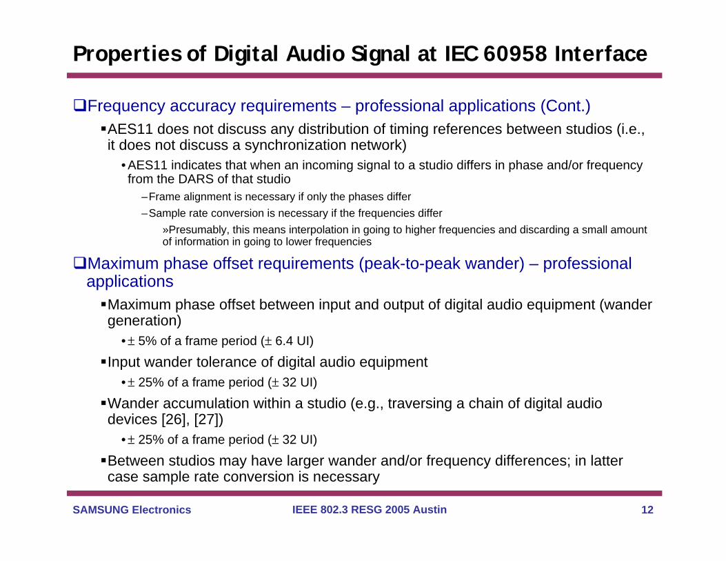
Frequency accuracy requirements – professional applications (Cont.)AES11 does not discuss any distribution of timing references between studios (i.e., it does not discuss a synchronization network)
• AES11 indicates that when an incoming signal to a studio differs in phase and/or frequency from the DARS of that studio
–Frame alignment is necessary if only the phases differ–Sample rate conversion is necessary if the frequencies differ
»Presumably, this means interpolation in going to higher frequencies and discarding a small amount of information in going to lower frequencies
Maximum phase offset requirements (peak-to-peak wander) – professional applications
Maximum phase offset between input and output of digital audio equipment (wander generation)
•± 5% of a frame period (± 6.4 UI)
Input wander tolerance of digital audio equipment•± 25% of a frame period (± 32 UI)
Wander accumulation within a studio (e.g., traversing a chain of digital audio devices [26], [27])
•± 25% of a frame period (± 32 UI)
Between studios may have larger wander and/or frequency differences; in latter case sample rate conversion is necessary

SAMSUNG Electronics IEEE 802.3 RESG 2005 Austin 13
Properties of Digital Audio Signal at IEC 60958 Interface
Jitter specificationsAs indicated earlier, jitter requirements for sampling clock are much tighter than jitter requirements at digital interface (receiver input)
•Sampling clock jitter requirement is driven by level of jitter that causes audible effects
–Depending on the particular audio source and jitter frequency, this can range from less than 1 ns rms to more than 100 ns rms [29], [30]
–Effect of jitter tends to be greater at higher jitter frequencies and higher audio source frequencies
•Digital interface jitter requirement is driven by need to perform clock and data recovery with acceptable bit error ratio (BER)
–Assumed that receiver and DAC can cope with any jitter within the interface requirement–Receiver and DAC will contain the necessary filtering to perform clock and data recovery,
and to bring the sampling clock jitter to within limits»Some implementations may use two-stage filtering process: wide band clock recovery circuit, followed by narrow band jitter cleanup filter
SAMSUNG Electronics IEEE 802.3 RESG 2005 Austin 14
Properties of Digital Audio Signal at IEC 60958 Interface
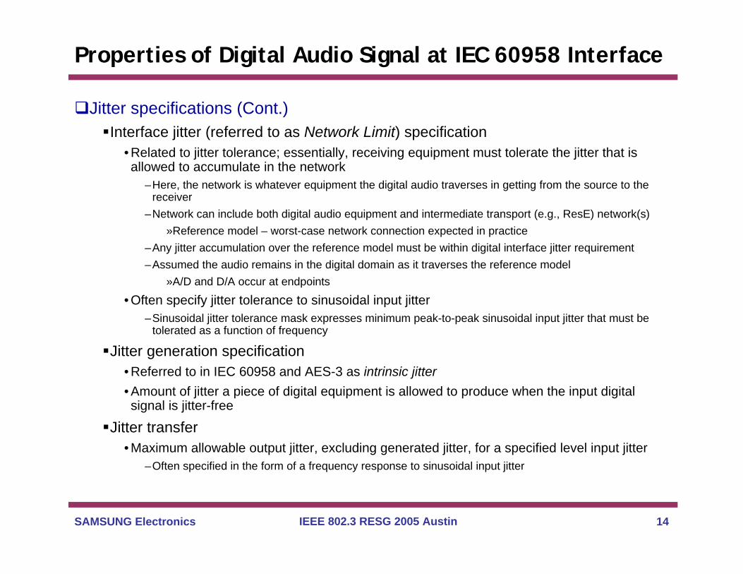
Jitter specifications (Cont.)Interface jitter (referred to as Network Limit) specification
• Related to jitter tolerance; essentially, receiving equipment must tolerate the jitter that is allowed to accumulate in the network
–Here, the network is whatever equipment the digital audio traverses in getting from the source to the receiver
–Network can include both digital audio equipment and intermediate transport (e.g., ResE) network(s)»Reference model – worst-case network connection expected in practice
–Any jitter accumulation over the reference model must be within digital interface jitter requirement–Assumed the audio remains in the digital domain as it traverses the reference model
»A/D and D/A occur at endpoints
• Often specify jitter tolerance to sinusoidal input jitter–Sinusoidal jitter tolerance mask expresses minimum peak-to-peak sinusoidal input jitter that must be
tolerated as a function of frequency
Jitter generation specification• Referred to in IEC 60958 and AES-3 as intrinsic jitter• Amount of jitter a piece of digital equipment is allowed to produce when the input digital signal is jitter-free
Jitter transfer• Maximum allowable output jitter, excluding generated jitter, for a specified level input jitter
–Often specified in the form of a frequency response to sinusoidal input jitter
SAMSUNG Electronics IEEE 802.3 RESG 2005 Austin 15
Properties of Digital Audio Signal at IEC 60958 Interface
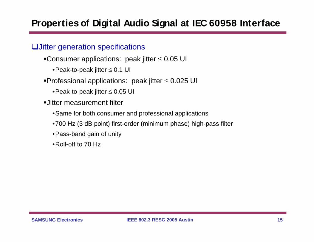
Jitter generation specificationsConsumer applications: peak jitter ≤ 0.05 UI
•Peak-to-peak jitter ≤ 0.1 UI
Professional applications: peak jitter ≤ 0.025 UI•Peak-to-peak jitter ≤ 0.05 UI
Jitter measurement filter•Same for both consumer and professional applications•700 Hz (3 dB point) first-order (minimum phase) high-pass filter•Pass-band gain of unity•Roll-off to 70 Hz
SAMSUNG Electronics IEEE 802.3 RESG 2005 Austin 16
Properties of Digital Audio Signal at IEC 60958 Interface
Jitter transfer specificationsConsumer applications
•Maximum gain peaking: 3 dB•No specification for jitter attenuation
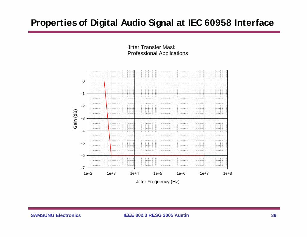
Professional applications•Maximum gain peaking: 2 dB•Jitter attenuation is not required, but if it is provided, it should be within the mask on the following slide
–No additional specification below 500 Hz (beyond the 2 dB gain peaking limit)–20 dB/decade roll-off between 500 Hz and 1 kHz, from 0 dB to –6 dB–Constant attenuation of –6 dB from 1 kHz to 10 MHz–See mask on following slide

SAMSUNG Electronics IEEE 802.3 RESG 2005 Austin 17
Properties of Digital Audio Signal at IEC 60958 Interface
Jitter Transfer MaskProfessional Applications
Jitter Frequency (Hz)
1e+2 1e+3 1e+4 1e+5 1e+6 1e+7 1e+8
Gai
n (d
B)
-7
-6
-5
-4
-3
-2
-1
0

SAMSUNG Electronics IEEE 802.3 RESG 2005 Austin 18
Properties of Digital Audio Signal at IEC 60958 Interface
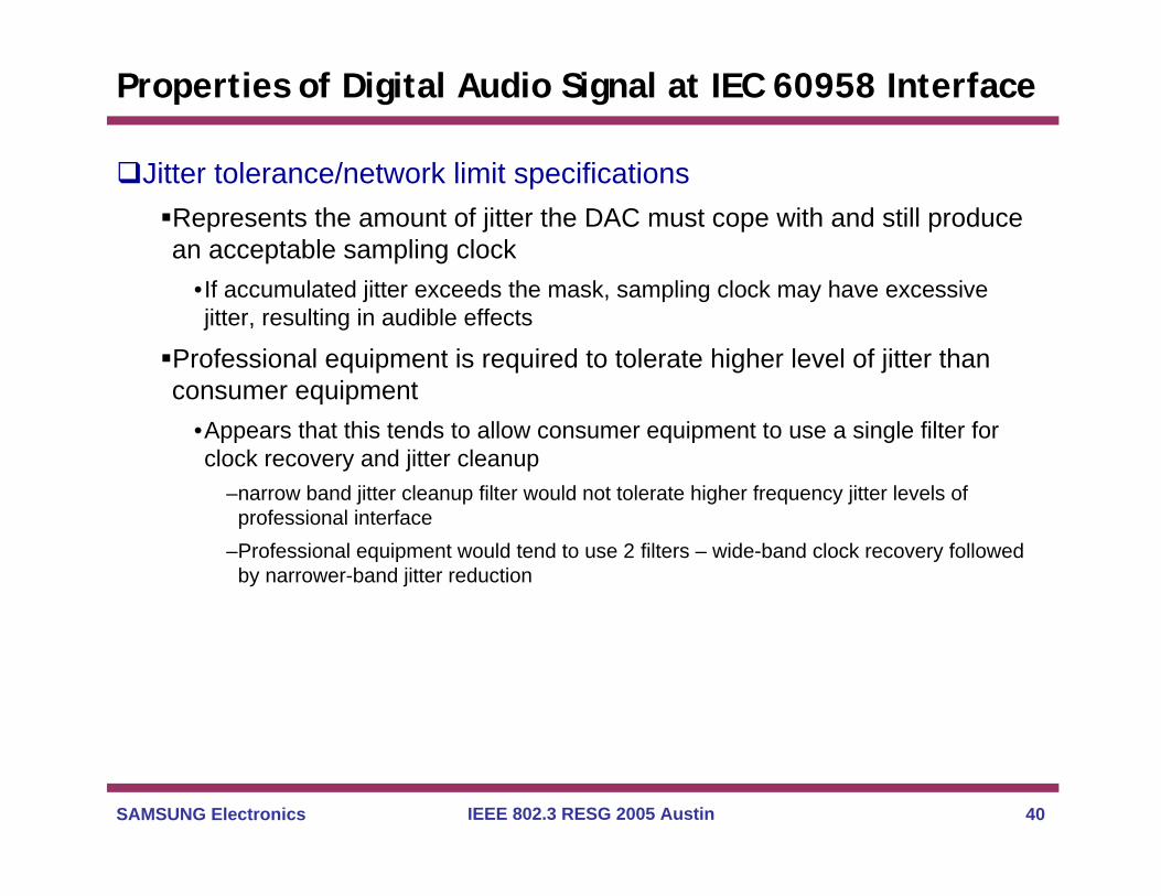
Jitter tolerance/network limit specificationsRepresents the amount of jitter the DAC must cope with and still produce an acceptable sampling clock
•If accumulated jitter exceeds the mask, sampling clock may have excessive jitter, resulting in audible effects
Professional equipment is required to tolerate higher level of jitter than consumer equipment
•Appears that this tends to allow consumer equipment to use a single filter for clock recovery and jitter cleanup
–narrow band jitter cleanup filter would not tolerate higher frequency jitter levels of professional interface
–Professional equipment would tend to use 2 filters – wide-band clock recovery followed by narrower-band jitter reduction

SAMSUNG Electronics IEEE 802.3 RESG 2005 Austin 19
Properties of Digital Audio Signal at IEC 60958 Interface
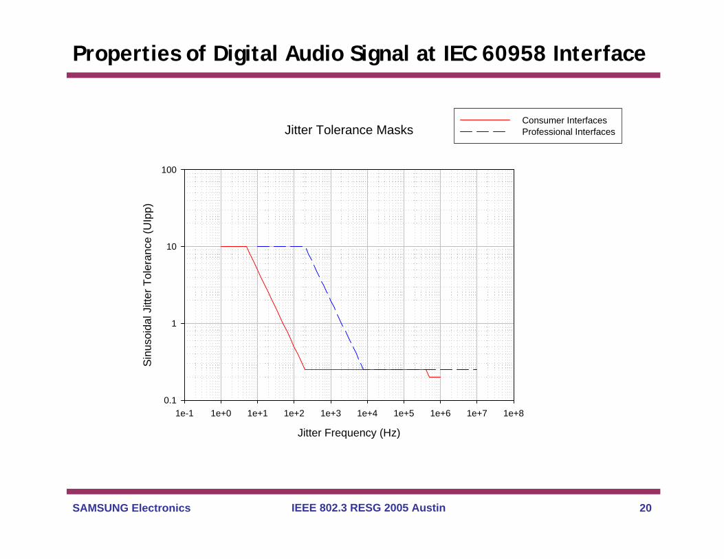
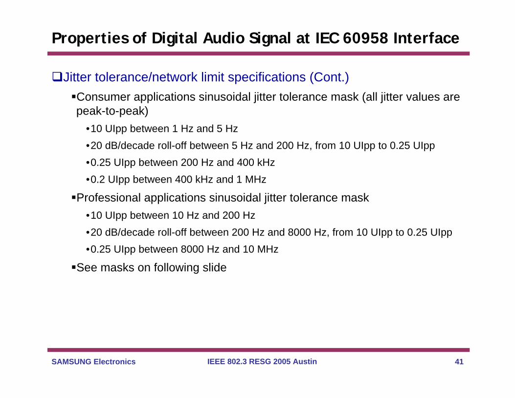
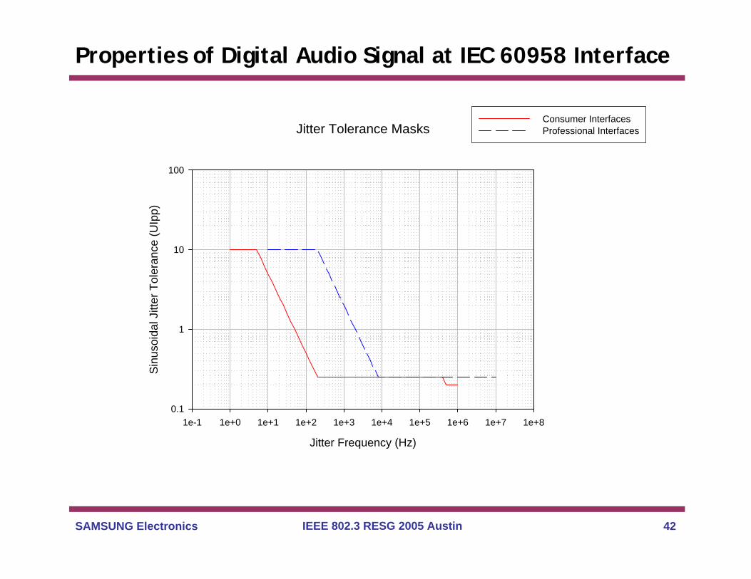
Jitter tolerance/network limit specifications (Cont.)Consumer applications sinusoidal jitter tolerance mask (all jitter values are peak-to-peak)
•10 UIpp between 1 Hz and 5 Hz•20 dB/decade roll-off between 5 Hz and 200 Hz, from 10 UIpp to 0.25 UIpp•0.25 UIpp between 200 Hz and 400 kHz•0.2 UIpp between 400 kHz and 1 MHz
Professional applications sinusoidal jitter tolerance mask •10 UIpp between 10 Hz and 200 Hz•20 dB/decade roll-off between 200 Hz and 8000 Hz, from 10 UIpp to 0.25 UIpp•0.25 UIpp between 8000 Hz and 10 MHz
See masks on following slide
SAMSUNG Electronics IEEE 802.3 RESG 2005 Austin 20
Properties of Digital Audio Signal at IEC 60958 Interface
Jitter Tolerance Masks
Jitter Frequency (Hz)
1e-1 1e+0 1e+1 1e+2 1e+3 1e+4 1e+5 1e+6 1e+7 1e+8
Sinu
soid
al J
itter
Tol
eran
ce (U
Ipp)
0.1
1
10
100
Consumer Interfaces Professional Interfaces
SAMSUNG Electronics IEEE 802.3 RESG 2005 Austin 21
Thank You
Backup
More detailed version of presentation, plus references
SAMSUNG Electronics IEEE 802.3 RESG 2005 Austin 23
Digital Audio - Background
High-level view of CD player (consumer application)Read CD
•Requires clock generator
Digital TransmitterDigital Receiver
•Recover data clock
D/A converter•Recover sampling clock
Produce analog audio (speakers, etc.)See schematic on next slide (based on figures in [17])Reference [17] provides a good introduction to digital audio
Can replace CD by analog audio source and D/A converterNeed clock generator for samplingSee schematic on next slide
SAMSUNG Electronics IEEE 802.3 RESG 2005 Austin 24
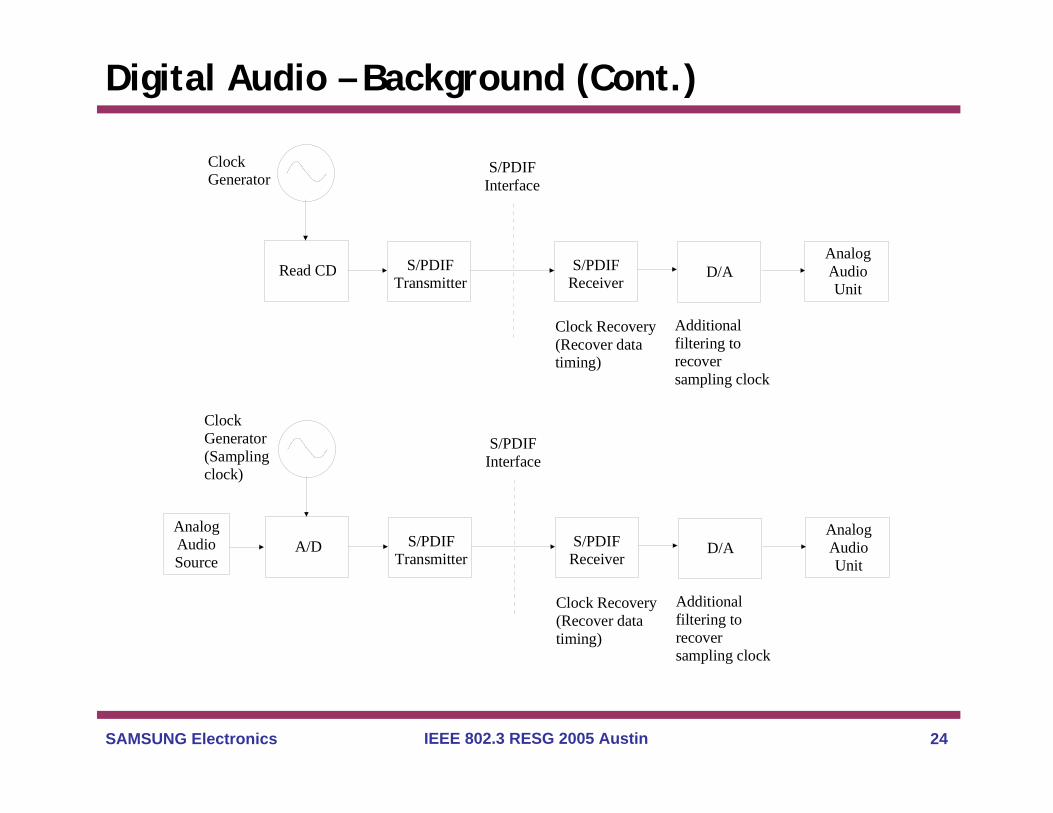
Digital Audio – Background (Cont.)
Read CD S/PDIFTransmitter
S/PDIFReceiver
D/AAnalogAudioUnit
AnalogAudioSource
S/PDIFInterface
ClockGenerator
Clock Recovery(Recover datatiming)
Additionalfiltering torecoversampling clock
A/D S/PDIFTransmitter
S/PDIFReceiver
D/AAnalogAudioUnit
S/PDIFInterface
ClockGenerator(Samplingclock)
Clock Recovery(Recover datatiming)
Additionalfiltering torecoversampling clock
SAMSUNG Electronics IEEE 802.3 RESG 2005 Austin 25
Digital Audio – Background (Cont.)
Digital audio sourceRead CD, at rate controlled by source clock generatorRead encoded audio from local server, at a rate controlled by source clock generatorSample analog audio source, at rate controlled by clock generator (sampling clock)
Transmit digital audio to receiverIn consumer applications, this interface is the standardized S/PDIF (Sony/Philips Digital Interface)Professional interfaces are also standardized (interface details described shortly)
Perform clock recovery at receiver and detect the incoming bitsPerform further filtering of recovered clock in or prior to D/A converter to produce sampling clock
Jitter/wander (especially jitter) requirements for sampling clock are much tighter than those needed for clock/data recoveryThe additional filtering in or prior to the D/A converter essentially “cleans up” the recovered data clockMore detail on digital audio jitter and wander described shortly
SAMSUNG Electronics IEEE 802.3 RESG 2005 Austin 26
Digital Audio Interface Standards
Two classes of interface, for two applications, are definedConsumer applicationsProfessional applications
Both interfaces (including jitter specifications) are standardized in IEC 60958Part 1: General (IEC 60958-1 [18])Part 3: Consumer applications (IEC 60958-3 [19])Part 4: Professional applications (IEC 60958-4 [20])The consumer interface is equivalent to the S/PDIF (Sony/Philips Digital Interface)The professional interface is equivalent to the AES3 specification [22]The professional interface is also equivalent, with some differences, to the EBU 3250-E specificationJitter specifications in IEC 60958-4, AES3, and EBU 3250-E are the sameJitter specifications in IEC 60958-3 and IEC 60958-4 (i.e., consumer and professional interfaces) have significant differences

SAMSUNG Electronics IEEE 802.3 RESG 2005 Austin 27
Digital Audio Interface Standards (Cont.)
Specification of nominal ratesProfessional applications – AES5 [23] and IEC 60988-4 [20]Consumer applications – AES5 and IEC 60958-3 [19]Note that [23] specifies the actual sampling rates
•[19] and [20] specify the coding of sampling rates in the frame overhead (not the actual frequency specifications)
Specification of wander/synchronizationStudio applications – AES11 [24]
•Specifies frequency accuracy, pull-in range, and maximum phase offset (peak-to-peak wander)
•Specifies Digital Audio Reference Signal (DARS)
Consumer applications – ICE 60958-3•Specifies frequency accuracy and pull-in range
SAMSUNG Electronics IEEE 802.3 RESG 2005 Austin 28
Properties of Digital Audio Signal at IEC 60958 Interface
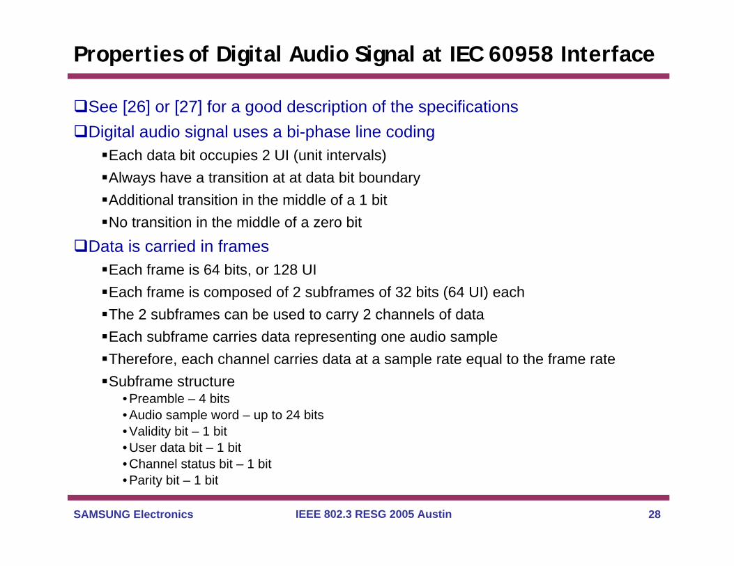
See [26] or [27] for a good description of the specificationsDigital audio signal uses a bi-phase line coding
Each data bit occupies 2 UI (unit intervals)Always have a transition at at data bit boundaryAdditional transition in the middle of a 1 bitNo transition in the middle of a zero bit
Data is carried in framesEach frame is 64 bits, or 128 UIEach frame is composed of 2 subframes of 32 bits (64 UI) eachThe 2 subframes can be used to carry 2 channels of dataEach subframe carries data representing one audio sampleTherefore, each channel carries data at a sample rate equal to the frame rateSubframe structure
• Preamble – 4 bits• Audio sample word – up to 24 bits• Validity bit – 1 bit• User data bit – 1 bit• Channel status bit – 1 bit• Parity bit – 1 bit
SAMSUNG Electronics IEEE 802.3 RESG 2005 Austin 29
Properties of Digital Audio Signal at IEC 60958 Interface
Data frames (cont.)Audio data samples need not use the full 24 bits
•A number of consumer applications use 16 bits•If fewer than 24 bits are used for audio data, the unused bits are padded with zeros
–Therefore, a specified frame rate implies a specified bit rate
•AES3 defines 4 bits of auxiliary data for the case where fewer than 20 bits of audio information are present ([26] and [27] indicate that this use is rare)
Detailed description of the validity, user data, channel status, and parity bits, as well as the preamble, are given in [18] – [20], [22], and are summarized in [26] and [27]
•The details differ for consumer and professional applications•The details are not important for the discussion here
SAMSUNG Electronics IEEE 802.3 RESG 2005 Austin 30
Properties of Digital Audio Signal at IEC 60958 Interface
Nominal frame ratesBasic rates defined in [23] are 44.1 kHz (consumer applications) and 48 kHz (professional applications) Corresponds to 5.6448 and 6.144 Mbit/s, respectivelyAlso define double, quadruple, half, and quarter rates in [23]
•Consumer applications – 11.025, 22.05, 88.2, 176.4 kHz–Corresponds to 1.4112, 2.8224, 11.2896, and 22.5792 Mbit/s
»Bits are the UIs described above, and not the 2-UI bits
•Professional applications – 12, 24, 96, 192 kHz–Corresponds to 1.536, 3.072, 12.288, and 24.576 Mbit/s
Coding of the rates in frame overhead defined in [19], [20]
SAMSUNG Electronics IEEE 802.3 RESG 2005 Austin 31
Properties of Digital Audio Signal at IEC 60958 Interface
Frequency accuracy requirementsThis is the amount the source (sampling) clock is allowed to deviate from nominal, in the long-runNote that the same long-term frequency accuracy requirement applies at all interfaces over sufficiently long time intervals
•This is because bits are not created or destroyed by the network–the long term average rate at which bits cross an interface is the same when the
averaging time is sufficiently long
•Note that frequencies averaged over shorter intervals at various interfaces may have deviations that are larger than the long-term frequency accuracy requirements
–Deviations over shorter time intervals are specified in the form of jitter and Maximum Time Interval Error (MTIE) requirements (see the third VG presentation referred to in the Introduction)
The specified long-term frequency accuracy is also the minimum long-term frequency offset the receiver must tolerate
•A ResE network inserted between the transmitter and receiver must also tolerate this frequency offset

SAMSUNG Electronics IEEE 802.3 RESG 2005 Austin 32
Properties of Digital Audio Signal at IEC 60958 Interface
Frequency accuracy requirements – Consumer applicationsIEC 60958-3 defines 3 levels of accuracy for the sampling clockLevel I (high accuracy mode): ± 50 × 10-6 (± 50 ppm)Level II (normal accuracy mode): ± 1000 × 10-6 (± 1000 ppm)Level III (variable pitch shifted clock mode): The standard indicates that signal in this mode can be received by specially designed receivers.
•A note indicates that the frequency range is under consideration, but that a range of 12.5% (125000 ppm) is envisaged
IEC 60958-3 indicates that receivers should be able to lock to signals with Level II accuracy
•I.e., ± 1000 ppm pull-in range•Indicates that if a receiver’s pull-in range is less, it should exceed the Level I tolerance (± 50 ppm) and shall be specified as a Level I receiver
SAMSUNG Electronics IEEE 802.3 RESG 2005 Austin 33
Properties of Digital Audio Signal at IEC 60958 Interface
Frequency accuracy requirements – professional applicationsAES11 specifies 2 levels of frequency tolerance
•Grade 1–frequency tolerance of ± 1 ppm–Pull-in range of ± 2 ppm
•Grade 2–frequency tolerance of ± 10 ppm (note that the ± 10 ppm tolerance is indicated in AES5
also)–Pull-in range of ± 50 ppm
•Equipment designed to provide a Grade 1 signal shall only be required to lock to other Grade 1 signals
AES11 defines the Digital Audio Reference Signal (DARS) for studio applications
•May be used to time all the equipment in a studio–May also time equipment by incoming audio or video signal
•DARS is classified as Grade 1 or Grade 2•DARS may be referenced to GPS
SAMSUNG Electronics IEEE 802.3 RESG 2005 Austin 34
Properties of Digital Audio Signal at IEC 60958 Interface
Frequency accuracy requirements – professional applications (Cont.)AES11 does not discuss any distribution of timing references between studios (i.e., it does not discuss a synchronization network)
• AES11 indicates that when an incoming signal to a studio differs in phase and/or frequency from the DARS of that studio
–Frame alignment is necessary if only the phases differ–Sample rate conversion is necessary if the frequencies differ
»Presumably, this means interpolation in going to higher frequencies and discarding a small amount of information in going to lower frequencies
Maximum phase offset requirements (peak-to-peak wander) – professional applications
Maximum phase offset between input and output of digital audio equipment (wander generation)
•± 5% of a frame period (± 6.4 UI)
Input wander tolerance of digital audio equipment•± 25% of a frame period (± 32 UI)
Wander accumulation within a studio (e.g., traversing a chain of digital audio devices [26], [27])
•± 25% of a frame period (± 32 UI)
Between studios may have larger wander and/or frequency differences; in latter case sample rate conversion is necessary
SAMSUNG Electronics IEEE 802.3 RESG 2005 Austin 35
Properties of Digital Audio Signal at IEC 60958 Interface
Jitter specificationsAs indicated earlier, jitter requirements for sampling clock are much tighter than jitter requirements at digital interface (receiver input)
•Sampling clock jitter requirement is driven by level of jitter that causes audible effects
–Depending on the particular audio source and jitter frequency, this can range from less than 1 ns rms to more than 100 ns rms [29], [30]
–Effect of jitter tends to be greater at higher jitter frequencies and higher audio source frequencies
•Digital interface jitter requirement is driven by need to perform clock and data recovery with acceptable bit error ratio (BER)
–Assumed that receiver and DAC can cope with any jitter within the interface requirement–Receiver and DAC will contain the necessary filtering to perform clock and data recovery,
and to bring the sampling clock jitter to within limits»Some implementations may use two-stage filtering process: wide band clock recovery circuit, followed by narrow band jitter cleanup filter

SAMSUNG Electronics IEEE 802.3 RESG 2005 Austin 36
Properties of Digital Audio Signal at IEC 60958 Interface
Jitter specifications (Cont.)Interface jitter (referred to as Network Limit) specification
• Related to jitter tolerance; essentially, receiving equipment must tolerate the jitter that is allowed to accumulate in the network
–Here, the network is whatever equipment the digital audio traverses in getting from the source to the receiver
–Network can include both digital audio equipment and intermediate transport (e.g., ResE) network(s)»Reference model – worst-case network connection expected in practice
–Any jitter accumulation over the reference model must be within digital interface jitter requirement–Assumed the audio remains in the digital domain as it traverses the reference model
»A/D and D/A occur at endpoints
• Often specify jitter tolerance to sinusoidal input jitter–Sinusoidal jitter tolerance mask expresses minimum peak-to-peak sinusoidal input jitter that must be
tolerated as a function of frequency
Jitter generation specification• Referred to in IEC 60958 and AES-3 as intrinsic jitter• Amount of jitter a piece of digital equipment is allowed to produce when the input digital signal is jitter-free
Jitter transfer• Maximum allowable output jitter, excluding generated jitter, for a specified level input jitter
–Often specified in the form of a frequency response to sinusoidal input jitter

SAMSUNG Electronics IEEE 802.3 RESG 2005 Austin 37
Properties of Digital Audio Signal at IEC 60958 Interface
Jitter generation specificationsConsumer applications: peak jitter ≤ 0.05 UI
•Peak-to-peak jitter ≤ 0.1 UI
Professional applications: peak jitter ≤ 0.025 UI•Peak-to-peak jitter ≤ 0.05 UI
Jitter measurement filter•Same for both consumer and professional applications•700 Hz (3 dB point) first-order (minimum phase) high-pass filter•Pass-band gain of unity•Roll-off to 70 Hz

SAMSUNG Electronics IEEE 802.3 RESG 2005 Austin 38
Properties of Digital Audio Signal at IEC 60958 Interface
Jitter transfer specificationsConsumer applications
•Maximum gain peaking: 3 dB•No specification for jitter attenuation
Professional applications•Maximum gain peaking: 2 dB•Jitter attenuation is not required, but if it is provided, it should be within the mask on the following slide
–No additional specification below 500 Hz (beyond the 2 dB gain peaking limit)–20 dB/decade roll-off between 500 Hz and 1 kHz, from 0 dB to –6 dB–Constant attenuation of –6 dB from 1 kHz to 10 MHz–See mask on following slide
SAMSUNG Electronics IEEE 802.3 RESG 2005 Austin 39
Properties of Digital Audio Signal at IEC 60958 Interface
Jitter Transfer MaskProfessional Applications
Jitter Frequency (Hz)
1e+2 1e+3 1e+4 1e+5 1e+6 1e+7 1e+8
Gai
n (d
B)
-7
-6
-5
-4
-3
-2
-1
0
SAMSUNG Electronics IEEE 802.3 RESG 2005 Austin 40
Properties of Digital Audio Signal at IEC 60958 Interface
Jitter tolerance/network limit specificationsRepresents the amount of jitter the DAC must cope with and still produce an acceptable sampling clock
•If accumulated jitter exceeds the mask, sampling clock may have excessive jitter, resulting in audible effects
Professional equipment is required to tolerate higher level of jitter than consumer equipment
•Appears that this tends to allow consumer equipment to use a single filter for clock recovery and jitter cleanup
–narrow band jitter cleanup filter would not tolerate higher frequency jitter levels of professional interface
–Professional equipment would tend to use 2 filters – wide-band clock recovery followed by narrower-band jitter reduction
SAMSUNG Electronics IEEE 802.3 RESG 2005 Austin 41
Properties of Digital Audio Signal at IEC 60958 Interface
Jitter tolerance/network limit specifications (Cont.)Consumer applications sinusoidal jitter tolerance mask (all jitter values are peak-to-peak)
•10 UIpp between 1 Hz and 5 Hz•20 dB/decade roll-off between 5 Hz and 200 Hz, from 10 UIpp to 0.25 UIpp•0.25 UIpp between 200 Hz and 400 kHz•0.2 UIpp between 400 kHz and 1 MHz
Professional applications sinusoidal jitter tolerance mask •10 UIpp between 10 Hz and 200 Hz•20 dB/decade roll-off between 200 Hz and 8000 Hz, from 10 UIpp to 0.25 UIpp•0.25 UIpp between 8000 Hz and 10 MHz
See masks on following slide
SAMSUNG Electronics IEEE 802.3 RESG 2005 Austin 42
Properties of Digital Audio Signal at IEC 60958 Interface
Jitter Tolerance Masks
Jitter Frequency (Hz)
1e-1 1e+0 1e+1 1e+2 1e+3 1e+4 1e+5 1e+6 1e+7 1e+8
Sinu
soid
al J
itter
Tol
eran
ce (U
Ipp)
0.1
1
10
100
Consumer Interfaces Professional Interfaces
SAMSUNG Electronics IEEE 802.3 RESG 2005 Austin 43
References
1. ITU-R Rec. BT.470-6, Conventional Television Systems, ITU-R, Geneva, 1998.
2. SMPTE 170M-1999, Composite Analog Video Signal – NTSC for Studio Applications, Society of Motion Picture and Television Engineers, 1999.
3. K. Blair Benson (Deceased, Editor and Coauthor) and Jerry Whitaker (Revised by), Television Engineering Handbook, Revised Edition, McGraw-Hill, New York, 1992.
4. Milton Kiver and Milton Kaufman, Television Electronics, Theory and Service, Eighth Ed., Van Nostrand Reinhold Company, New York, 1983.
5. Tektronix, PCR Measurements, Tektronix, Inc., Document 25W-14617-1, 2003 (available via http://www.tektronix.com/video_audio )
6. Tian-Sheuan Chang, Basics of Video, VG presentation for Lecture 2 of Multimedia Communication Course, adapted from slides of Prof. YaoWang and Prof. Hang, National Chiao Tung University, Taiwan (available at http://twins.ee.nctu.edu.tw/courses/multimedia_c_05spring/index.html )
7. SMPTE 259M-1997, 10-Bit 4:2:2 Component and 4fSC Composite Digital Signals – Serial Digital Interface, Society of Motion Picture and Television Engineers, 1997.
8. ITU-R Rec. BT.601-5, Studio Encoding Parameters of Digital Television for Standard 4:3 and Wide-Screen 16:9 Aspect Ratios, ITU-R, Geneva, 1995.
SAMSUNG Electronics IEEE 802.3 RESG 2005 Austin 44
References (Cont.)
9. SMPTE 292M-1998, Bit-Serial Digital Interface for High-Definition Television Systems, Society of Motion Picture and Television Engineers, 1998.
10. SMPTE 318M-1999 (Revision of SMPTE RP 154-1994), Synchronization of 59.94- or 50-Hz Related Video and Audio Systems in Analog and Digital Areas – Reference Signals, Society of Motion Picture and Television Engineers, 1999.
11. SMPTE 295M-1997, 1920 × 1080 50 Hz – Scanning and Interfaces, Society of Motion Picture and Television Engineers, 1997.
12. SMPTE 296M-2001, 1280 × 720 Progressive Image Sample Structure –Analog and Digital Representation and Analog Interfaces, Society of Motion Picture and Television Engineers, 2001.
13. ISO/IEC 13818-2, Information technology – Generic coding of moving pictures and associated audio information: Video, ISO/IEC, Geneva, 2000 (same as ITU-T Rec. H.262, ITU-T, Geneva, 2000).
14. ISO/IEC 13818-3, Information technology – Generic coding of moving pictures and associated audio information: Audio, ISO/IEC, Geneva, 1996.
15. ISO/IEC 13818-1, Information technology – Generic coding of moving pictures and associated audio information: Systems, ISO/IEC, Geneva, 2000 (same as ITU-T Rec. H.222.0, ITU-T, Geneva, 2000).
SAMSUNG Electronics IEEE 802.3 RESG 2005 Austin 45
References (Cont.)
16. Tektronix, A Guide to MPEG Fundamentals and Protocol Analysis (including DVB and ATSC), Tektronix, Inc., Document 25W-11418-1, 2002 (available via http://www.tektronix.com/video_audio ).
17. DIGITabilit: crash course on digital audio interfaces (parts 1.1 – 1.5), available via http://www.tnt-audio.com/clinica/diginterf1_e.html (links to all 5 parts at the end of part 1)
18. IEC 60958-1, Digital Audio Interface – Part1: General, International Electrotechnical Commission, Geneva, 2004.
19. IEC 60958-3, Digital Audio Interface – Part3: Consumer Applications, International Electrotechnical Commission, Geneva, 2003.
20. IEC 60958-4, Digital Audio Interface – Part4: Professional Applications (TA4), International Electrotechnical Commission, Geneva, 2003.
21. EBU Tech. 3250-E, Specification of the Digital Audio Interface, European Broadcasting Union, Geneva, 2004.
22. AES3-2003, AES Recommended practice for digital audio engineering --Serial transmission format for two-channel linearly represented digital audio data (Revision of AES3-1992, including subsequent amendments), Audio Engineering Society, 2003.

SAMSUNG Electronics IEEE 802.3 RESG 2005 Austin 46
References (Cont.)
23. AES5-2003: AES recommended practice for professional digital audio --Preferred sampling frequencies for applications employing pulse-code modulation (Revision of AES5-1997), Audio Engineering Society, 2003.
24. AES11-2003: AES recommended practice for digital audio engineering -Synchronization of digital audio equipment in studio operations (Revision of AES11-1997), Audio Engineering Society, 2003.
25. Julian Dunn, Jitter Theory, Audio Precision Technote, TN-23, 2000 (available via http://www.audioprecsion.com)
26. Julian Dunn, The AES3 and IEC60958 Digital Interface, Audio PrecisionTechnote, TN-26, 2001 (available via http://www.audioprecsion.com)
27. Julian Dunn, Measurement Techniques for Digital Audio, Audio Precision Application Note #5, 2004 (available via http://www.audioprecsion.com)
28. Julian Dunn, Barry A. McKibben, Roger Talyor, Chris Travis, Towards Common Specifications for Digital Audio Interface Jitter, 95th AES Convention, Preprint 3705, New York, October, 1993.
29. Julian Dunn, Considerations for Interfacing Digital Audio Equipment to the Standards AES-3, AES-5, and AES-11, AES 10th International Conference, Preprint 3712, London, September, 1991
SAMSUNG Electronics IEEE 802.3 RESG 2005 Austin 47
References (Cont.)
30. Eric Benjamin and Benjamin Gannon, Theoretical and Audible Effects of Jitter on Digital Audio Quality, 105th AES Convention, Preprint Preprint 4826, San Francisco, August, 1998.
31. Michael Orzessek and Peter Somer, ATM and MPEG-2, Integrating Digital Video into Broadband Networks, Prentice Hall PTR, Upper Saddle River, NJ, 1998.
32. Tektronix, PCR Measurements, Tektronix, Inc., Document 25W-14617-1, 2003 (available via http://www.tektronix.com/video_audio ).
33. Tektronix, A Layman’s Guide to PCR Measurements, Tektronix, Inc., Technical Brief, Document 25W-14706-0, 2001 (available via http://www.tektronix.com/video_audio ).
34. ETSI TR 101 290, Digital Video Broadcasting (DVB): Measurement guidelines for DVB systems, V.1.2.1 (2001-05).
35. ITU-T Recommendation G.810, Definitions and Terminology for Synchronization Networks, ITU-T, Geneva, August, 1996, Corrigendum 1, November, 2001.
36. Stefano Bregni, Synchronization of Digital Telecommunications Networks, Wiley, New York, 2002.
37. Geoffrey M. Garner, Timing in Global Optical Networks, Optical Networks Magazine, January/February, 2003, pp. 36 – 52.
SAMSUNG Electronics IEEE 802.3 RESG 2005 Austin 48
References (Cont.)
38. ISO/IEC 13818-9, Information technology – Generic coding of moving pictures and associated audio information: Extension for real-time interface for systems decoders, ISO/IEC, Geneva, 1996.
39. T1A1.1/2000-012R2, Draft American National Standard for Transport of MPEG2 Encoded Video over ATM, 2000, (available via http://www.atis.org).
40. Dan Wolaver, Calculation of DS3 Video Codec Phase Transfer, Tektronix Contribution to Committee T1X1.3, T1X1.3/96-063, July, 1996 (available via http://www.atis.org).
41. Dan Wolaver, Comparison of MTIE, Frequency Response, and Derivatives as Bounds on Phase, Tektronix Contribution to Committee T1X1.3, T1X1.3/96-064, July, 1996 (available via http://www.atis.org).
42. Ralf Steinmetz, Human Perception of Jitter and Media Synchronization, IEEE JSAC, Vol. 14, No. 1, January, 1996, pp. 61 – 72.
43. Alexei Beliaev, Latency Sensitive Application Examples, Gibson Labs, part of Residential Ethernet Tutorial, IEEE 802.3 meeting, March, 2005.