description of the main s&t results/foregrounds
TRANSCRIPT
Description of the main S&T results/foregrounds The main objectives of the project and the achieved results will be commented upon one at the time in the below table. Following this section a paragraph explaining the work done in each WP will be presented.
Project objectives and achievements at M48
Project objectives/ targets Status at M48 Extra
comments/explanation
Electrical efficiency (Peak) 35% net
AC efficiency
Gross Efficiency measured at EIFER @713 W: 44.7% Efficiency net: > 40.0% (@PI efficiency of 90%), cf. D5.5
The system at EIFER was not equipped with a grid tied PI, therefore, the net efficiency is a calculated value. It was planned to test higher FU by EIFER, but due to an early end of the test this was not possible.
Electrical efficiency (Nominal avg.)
30% net AC efficiency
Gross Efficiency measured at EIFER @713 W: 44.6% Efficiency net: > 40.0% (@PI efficiency of 90%), cf. D5.5
The system at EIFER was not equipped with a grid tied PI, therefore, the net efficiency is a calculated value.
Total efficiency of the system reached
values up to 90%
EIFER has measured a total efficiency of the system to 78,9 %.
Project objectives/ targets Status at M48 Extra comments/explanation
Modulation range demonstrated of
4:1 in terms of gas input
A modulation of 1.8:1 was achieved at EIFER
Modulation of gas input above 1.8:1 could be avoided, thanks to the improved flow distribution inside the stack. Thanks to the new design, which is protected by three patents, the fuel utilization could be increased by 25% from FU = 60% up to FU = 75% at nominal power.
5000 hours of operation
At HTceramix a long-term tests achieved an operation of 4000 h (close to the 5000 hour objective of Asterix3).
The long term tests at CNR failed due to a failure outside the HB.
10 thermal cycles
By HTc more than 10 thermal cycles have been reached, by DTP four thermal cycles have been achieved (during the 200 + hour test).
Due to the unforeseen HoTbox™ breakdowns at EIFER the thermal cycle test was not performed,
Integration of an auxiliary heater
Achieved.
Integration with the heating system
and storage
Achieved.
Injection of AC electric output to the
grid
Achieved.
Project objectives/ targets Status at M48 Extra comments/explanation
Ability to start-up and shut-down
without forming gas
Two methods have been developed to protect the Ni against oxidation:
a. ICCP: also referred to as electrical protection
b. SSCP: also referred to as Sub-Stoichiometric Combustion Protection
The ICCP is not implemented on the system. However, the electronic hardware needed is designed and assembled and had been tested by DTP on a different SOFC stack platform. A second option beside the ICCP, the SSCP had been tested successfully at HTc. A measure to reduce the CO content during the sub-stoichiometric combustion have been designed, cf.WP3 chapter.
WP2 – System simulation and Design specification
Main objectives of WP2 (System simulation and Design specification) were:
Simulate a 2nd generation hybrid system and define system specifications
Update the system design with simulations including an auxiliary heat pump
Definition of power conditioning devices specifications. For reaching these targets, two tasks were defined:
Task 2.1 - Initial Proof of Concept system specification
Task 2.2 - System simulations including a heat pump Task 1 resulted in the definition of the technical characteristics of the system to be developed in terms of power and efficiencies. The study is based on a sensitivity analysis of key parameters such as:
Load curve of the heat demand (annual profile and value): 2 load curves have been used (16 MWh/yr and 24 MWh/yr).
Water tank size (from 500 l to 2,000 l).
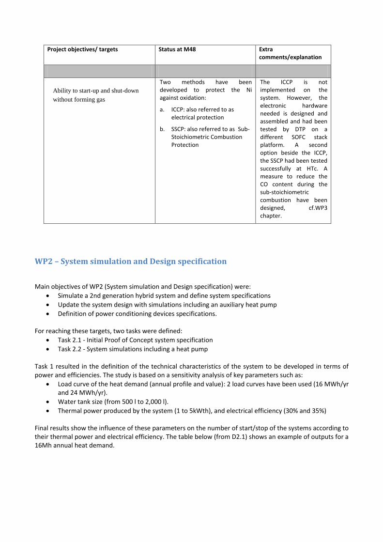
Thermal power produced by the system (1 to 5kWth), and electrical efficiency (30% and 35%) Final results show the influence of these parameters on the number of start/stop of the systems according to their thermal power and electrical efficiency. The table below (from D2.1) shows an example of outputs for a 16Mh annual heat demand.
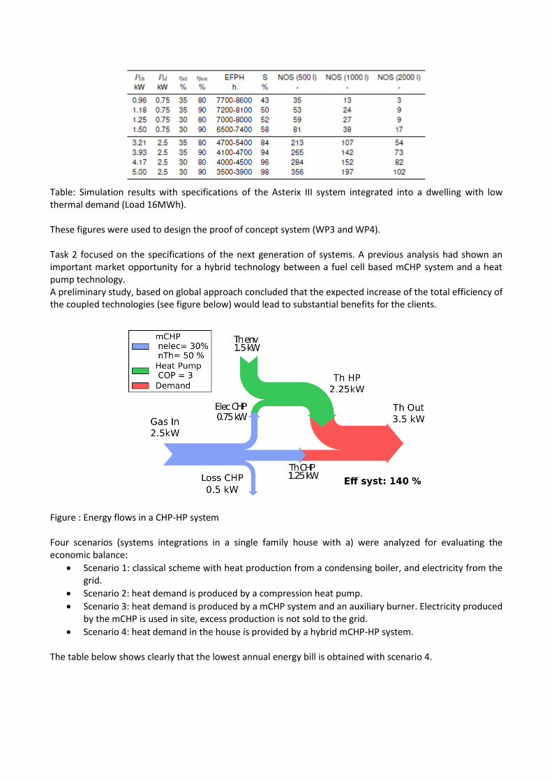
Table: Simulation results with specifications of the Asterix III system integrated into a dwelling with low thermal demand (Load 16MWh). These figures were used to design the proof of concept system (WP3 and WP4). Task 2 focused on the specifications of the next generation of systems. A previous analysis had shown an important market opportunity for a hybrid technology between a fuel cell based mCHP system and a heat pump technology. A preliminary study, based on global approach concluded that the expected increase of the total efficiency of the coupled technologies (see figure below) would lead to substantial benefits for the clients.
Figure : Energy flows in a CHP-HP system Four scenarios (systems integrations in a single family house with a) were analyzed for evaluating the economic balance:
Scenario 1: classical scheme with heat production from a condensing boiler, and electricity from the grid.
Scenario 2: heat demand is produced by a compression heat pump.
Scenario 3: heat demand is produced by a mCHP system and an auxiliary burner. Electricity produced by the mCHP is used in site, excess production is not sold to the grid.
Scenario 4: heat demand in the house is provided by a hybrid mCHP-HP system. The table below shows clearly that the lowest annual energy bill is obtained with scenario 4.
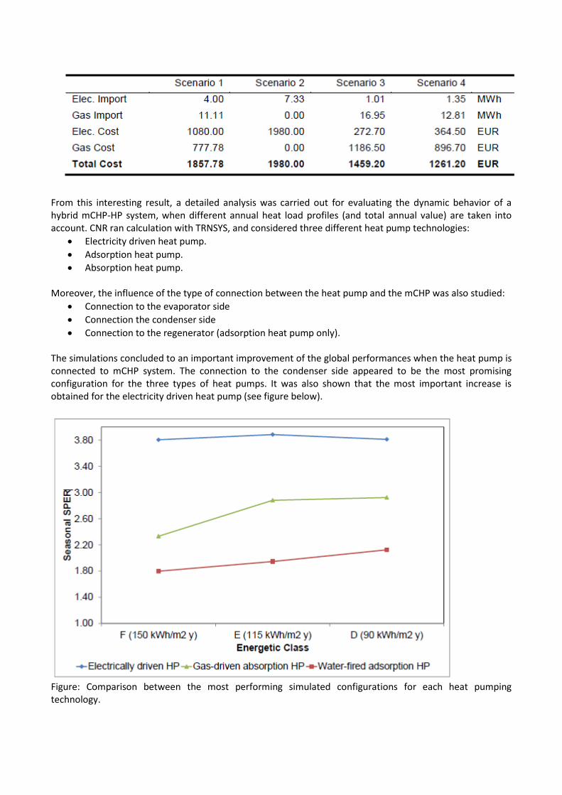
From this interesting result, a detailed analysis was carried out for evaluating the dynamic behavior of a hybrid mCHP-HP system, when different annual heat load profiles (and total annual value) are taken into account. CNR ran calculation with TRNSYS, and considered three different heat pump technologies:
Electricity driven heat pump.
Adsorption heat pump.
Absorption heat pump. Moreover, the influence of the type of connection between the heat pump and the mCHP was also studied:
Connection to the evaporator side
Connection the condenser side
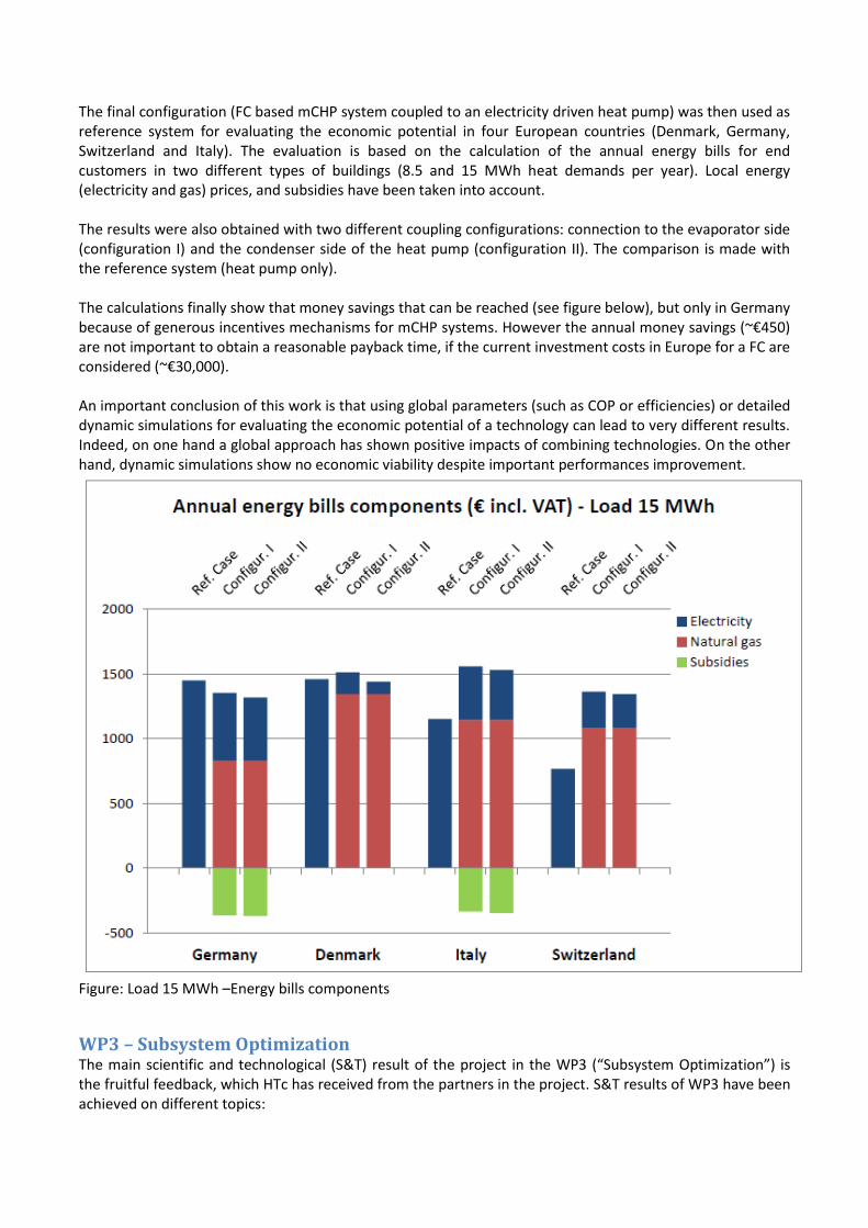
Connection to the regenerator (adsorption heat pump only). The simulations concluded to an important improvement of the global performances when the heat pump is connected to mCHP system. The connection to the condenser side appeared to be the most promising configuration for the three types of heat pumps. It was also shown that the most important increase is obtained for the electricity driven heat pump (see figure below).
Figure: Comparison between the most performing simulated configurations for each heat pumping technology.
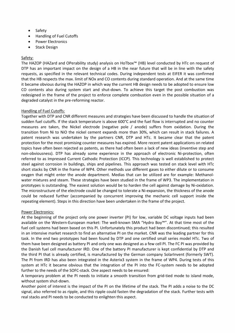
The final configuration (FC based mCHP system coupled to an electricity driven heat pump) was then used as reference system for evaluating the economic potential in four European countries (Denmark, Germany, Switzerland and Italy). The evaluation is based on the calculation of the annual energy bills for end customers in two different types of buildings (8.5 and 15 MWh heat demands per year). Local energy (electricity and gas) prices, and subsidies have been taken into account. The results were also obtained with two different coupling configurations: connection to the evaporator side (configuration I) and the condenser side of the heat pump (configuration II). The comparison is made with the reference system (heat pump only). The calculations finally show that money savings that can be reached (see figure below), but only in Germany because of generous incentives mechanisms for mCHP systems. However the annual money savings (~€450) are not important to obtain a reasonable payback time, if the current investment costs in Europe for a FC are considered (~€30,000). An important conclusion of this work is that using global parameters (such as COP or efficiencies) or detailed dynamic simulations for evaluating the economic potential of a technology can lead to very different results. Indeed, on one hand a global approach has shown positive impacts of combining technologies. On the other hand, dynamic simulations show no economic viability despite important performances improvement.
Figure: Load 15 MWh –Energy bills components
WP3 – Subsystem Optimization The main scientific and technological (S&T) result of the project in the WP3 (“Subsystem Optimization”) is the fruitful feedback, which HTc has received from the partners in the project. S&T results of WP3 have been achieved on different topics:
Safety
Handling of Fuel Cutoffs
Power Electronics
Stack Design Safety: The HAZOP (HAZard and OPerability study) analysis on HoTbox™ (HB) level conducted by HTc on request of DTP has an important impact on the design of a HB in the near future that will be in line with the safety requests, as specified in the relevant technical codes. During independent tests at EIFER it was confirmed that the HB respects the max. limit of NOx and CO contents during standard operation. And at the same time it became obvious during the HAZOP in which way the current HB design needs to be adopted to ensure low CO contents also during system start and shut-down. To achieve this target the post combustion was redesigned in the frame of the project to enforce complete combustion even in the possible situation of a degraded catalyst in the pre-reforming reactor. Handling of Fuel Cutoffs: Together with DTP and CNR different measures and strategies have been discussed to handle the situation of sudden fuel cutoffs. If the stack temperature is above 600°C and the fuel flow is interrupted and no counter measures are taken, the Nickel electrode (negative pole / anode) suffers from oxidation. During the transition from Ni to NiO the nickel cement expands more than 30%, which can result in stack failures. A patent research was undertaken by the partners CNR, DTP and HTc. It became clear that the patent protection for the most promising counter measures has expired. More recent patent applications on related topics have often been rejected as patents, as there had often been a lack of new ideas (inventive step and non-obviousness). DTP has already some experience in the approach of electronic Ni-protection, often referred to as Impressed Current Cathodic Protection (ICCP). This technology is well established to protect steel against corrosion in buildings, ships and pipelines. This approach was tested on stack level with HTc short stacks by CNR in the frame of WP4. Other methods use different gases to either dilute or to consume oxygen that might enter the anode department. Medias that can be utilized are for example: Methanol-water mixtures and steam. These strategies have been studied in the frame of WP3. The implementation in prototypes is outstanding. The easiest solution would be to harden the cell against damage by Ni-oxidation. The microstructure of the electrode could be changed to tolerate a Ni-expansion, the thickness of the anode could be reduced further (accompanied by concurrent improving the mechanic cell support inside the repeating element). Steps in this direction have been undertaken in the frame of the project. Power Electronics: At the beginning of the project only one power inverter (PI) for low, variable DC voltage inputs had been available on the Western-European market: The well-known SMA “Hydro Boy™”. At that time most of the fuel cell systems had been based on this PI. Unfortunately this product had been discontinued; this resulted in an intensive market research to find an alternative PI on the market. CNR was the leading partner for this task. In the end two prototypes had been found by DTP and one certified small series model HTc. Two of them have been designed as battery PI and only one was designed as a few cell PI. The FC PI was provided by the Danish fuel cell manufacturer IRD. One of the battery PI manufacturer is kept confidential by DTP and the third PI that is already certified, is manufactured by the German company SolarInvent (formerly SWT). The PI from IRD has also been integrated in the Asterix3 system in the frame of WP4. During tests of this system at HTc it became obvious that the integration of the PI into the FC-system needs to be adopted further to the needs of the SOFC-stack. One aspect needs to be ensured: A temporary problem at the PI needs to initiate a smooth transition from grid-tied mode to island mode, without system shut-down. Another point of interest is the impact of the PI on the lifetime of the stack. The PI adds a noise to the DC signal, also referred to as ripple, and this ripple could fasten the degradation of the stack. Further tests with real stacks and PI needs to be conducted to enlighten this aspect.
Stack Design: The most significant S&T result has been achieved on stack level. Two stack related patents have been filed by HTc and have been accepted. A third patent application is in preparation. The two patents protect the media distribution ideas and the third will protect ideas to improve the stack sealing. These patent ideas have been implemented in the frame of the project into the Asterix3 stack design. By means of these inventions the fuel utilization (FU) on stack level could be increased above values of 70%, high FU is the key factor to increase the electrical efficiency of the stack. Other measures have improved the robustness of the stack against vibration and thermal cycles. The objective of 10 cycles per year seems to be realistic with the new design.
WP4 - Systems development A total of three systems are built
System 1 is built as a prototype and sent to EIFER for testing. The system was equipped with load bank instead of DCAC Inverter, to promote the work of the project because intended DCAC Inverter was not finished
System 2 and 3 are built as second generation systems with integrated DCAC Inverter.
Due to hotbox delays and time pressure, the electrical anode protection is not implemented on system`s (However, electrical anode protection is designed and components for anode protection are made.)
One of the systems is sent to the HTceramix/SOFC POWER for further testing, while the second system will be in Dantherm Power lab. Both systems are equipped with DCAC Inverter.
The Dantherm Power system is tested as a micro-CHP system which is briefly described in the below:
Micro- CHP system test
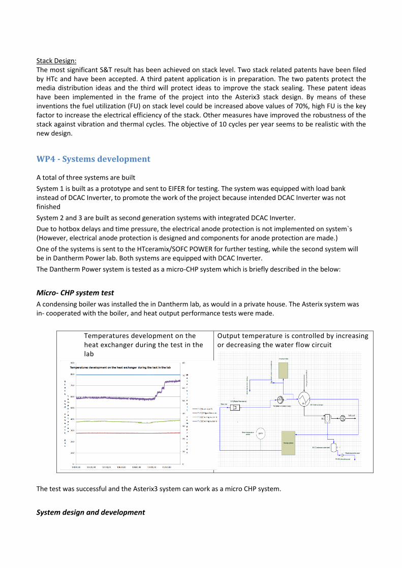
A condensing boiler was installed the in Dantherm lab, as would in a private house. The Asterix system was in- cooperated with the boiler, and heat output performance tests were made.
Temperatures development on the heat exchanger during the test in the lab
Output temperature is controlled by increasing or decreasing the water flow circuit
The test was successful and the Asterix3 system can work as a micro CHP system.
System design and development

Design of the system is complete and ready to be used to produce systems.
System is integrated into a gas-tight cabinet.
Air intake and exhaust gas outlet proceeds via the balanced flue pipe dimensions 80/125 mm
The overall system specifications are as follows:
System specification
General Dimensions: 1780 x 800 x 600 [mm] (H x W x D) Weight: 326 [kg]
AC power connection System supplied with AC power via the IEC connector on the back of the system. The same connection is used to supply power to the grid.
Fuel supply
System supplied via Standard ½ "pipe stub with male thread (BSPT). System is designed to use natural gas or methane gas, inlet pressure 25 [mbar]
Forming gas supply
Forming gas is supplied to the system through standard quick-disconnect coupling with integrated check
valve. Forming gas flow is adjustable between 5 and 30 L / min, (3 Asterix use 15L / min)
Cooling water connections Standard ½” pipe stubs with male thread BSPT
Exhaust connection
The air inlet and exhaust gas outlet is through standard flue pipe dimensions 80/125 mm
Condensate outlet
The condensate outlet of the system is through the 6 mm flexible tube that can be directly fed to the drain
Water circuit relief drain
Performed with 12 mm plastic hose on the back side of the system
Condensate drain from the flue
Through 12 mm plastic tube on the back side of the system
Internet connection
Via standard RJ45
Control computer
The system is equipped with a Beckhoof computer

Picture shows Asterix system ready for use Picture shows Asterix system taken from Auto CAD
Fuel cell control system
Based on the input from HTc, Dantherm has developed a full control system for the fuel cell system based on PLC technology and with a special setup for the chosen inverter.
The IO list has been provided, all hardware has been designed, software has been programmed, and the control system has been built, installed and testet.
HAZOP
In cooperation with HTceramix, a HAZOP is prepared for the system.
HAZOP in-cooperates the use of forming gas as the anode protection.
This means the safety chain on the system, is designed to take into account, that forming gas is used as the anode protection.
If electric anode protection should be implemented, HAZOP and safety chain needs to be revised, to always ensure that personnel and equipment do not suffer damage.
As an inspiration to find parameters for the risk assessment clause 4 of IEC 62282-3-300 have been used.

Fuel processing system
Oxidant processing system
Ventilationsystem
Thermal management system
Fuel cell module
Water treatment system
Automatic control system
Power conditioning
system
Power inputs electric, thermal
Fuel
Air
Water
Formier gas Internal power needs
Recovered heat
Waste heat
Useable power electrical
Discharge water
Exhaust gases, ventilation
Onboard energy storage
Fuel cell power system
Diagram of generalized cell system from IEC 62282
Picture shows the block diagram for Asterix 3 safety chain
Documentation
The 2 systems Dantherm Power have sent to EIFER and HTceramix have bee n accompanied by the following documentation:
HAZOP on the system
Installation guide
Software guide
Document on how to dismantle the hotbox
Startup procedure Asterix3;
Thermocouple connector assembly
Safety aspects of Asterix III in emergency
WP5 – Testing and validation
The objectives of this work package are:
To define experimental program and establish optimal operation process
To show the general capabilities of the Asterix m-CHP appliance.
To demonstrate extended continuous operation.
To validate operating performance of key system components.
To demonstrate operation and system response under start-up, power cycling, thermal cycling, and normal and emergency shutdown conditions.
Because of the major technical and strategic changes that occurred during the project, it has not been possible to test two generations of systems at EIFER and at CNR. These changes have had also a strong impact on the content of the different tasks in this work package. However, the partners agreed each time on a common position, and this resulted on the assembling of a system which was tested at EIFER in October 2014. Two stacks have been tested at CNR.
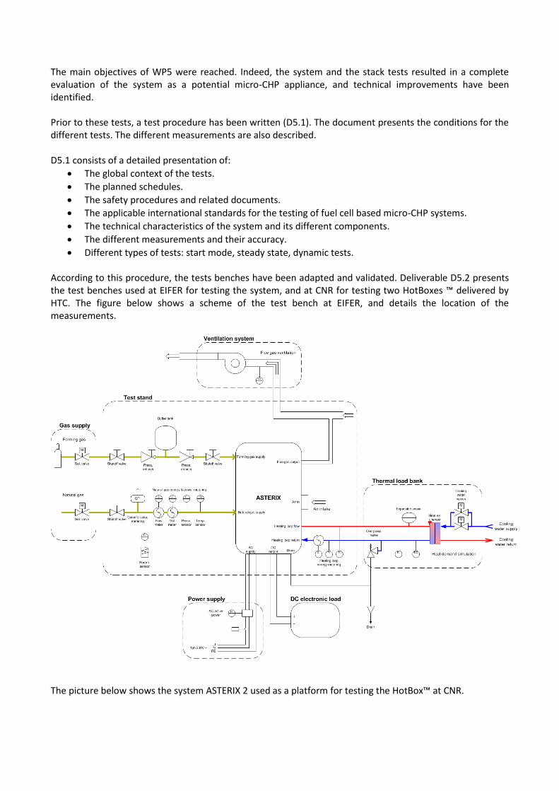
The main objectives of WP5 were reached. Indeed, the system and the stack tests resulted in a complete evaluation of the system as a potential micro-CHP appliance, and technical improvements have been identified. Prior to these tests, a test procedure has been written (D5.1). The document presents the conditions for the different tests. The different measurements are also described. D5.1 consists of a detailed presentation of:
The global context of the tests.
The planned schedules.
The safety procedures and related documents.
The applicable international standards for the testing of fuel cell based micro-CHP systems.
The technical characteristics of the system and its different components.
The different measurements and their accuracy.
Different types of tests: start mode, steady state, dynamic tests. According to this procedure, the tests benches have been adapted and validated. Deliverable D5.2 presents the test benches used at EIFER for testing the system, and at CNR for testing two HotBoxes ™ delivered by HTC. The figure below shows a scheme of the test bench at EIFER, and details the location of the measurements.
The picture below shows the system ASTERIX 2 used as a platform for testing the HotBox™ at CNR.

The system has been assembled by DANTHERM POWER (D5.3) and the staffs have been trained before system’s commissioning (D5.4). After verification and analysis, the results (powers, performances, flue gas emissions) were reported in a final document (D5.5). As an example, the table below contains the main results obtained during the steady state tests. Current level [A] 5 10 15 15
Return temp set point [°C] 30 40 30 40
Measuring time [hh:mm:ss] 00:56:40 06:41:30 03:00:30 06:00:10
Measuring time [s] 3400 24090 10830 21610
Consumed gas volume [m³] 0,09 0,99 0,51 1,02
Average gas flow [m³/h] 0,095 0,148 0,170 0,170
Average LHV [kWh/m³] 10,04 9,99 10,02 10,01
Average HHV [kWh/m³] 11,11 11,06 11,10 11,09
Average Z 0,944 0,939 0,939 0,940
Average gas power LHV [kW] 0,903 1,388 1,596 1,599
Average gas power HHV [kW] 1,000 1,537 1,767 1,771
Average flow temp [°C] 39,3 60,7 50,8 58,1
Average return temp [°C] 29,9 38,9 29,7 39,1
Average delta T [°C] 9,4 21,8 21,0 19,0
Average flue gas temp [°C] 43,1 47,5 43,3 48,2
Average heating loop flow [lpm] 0,84 0,46 0,54 0,55
Average thermal power [kW] 0,545 0,689 0,793 0,719
Average active power consumption [kW] -0,238 -0,241 -0,248 -0,253
Average reactive power consumption [kW] -0,185 -0,198 -0,192 -0,205
Average active power DC [W] 227,1 517,3 713,0 713,0
DC Electrical efficiency LHV [%] 25,2 37,3 44,7 44,6
Thermal efficiency LHV [%] 60,3 49,7 49,7 44,9
Electrical efficiency LHV [%] -1,2 19,9 29,1 28,8
Overall efficiency LHV [%] 59,1 69,6 78,9 73,7
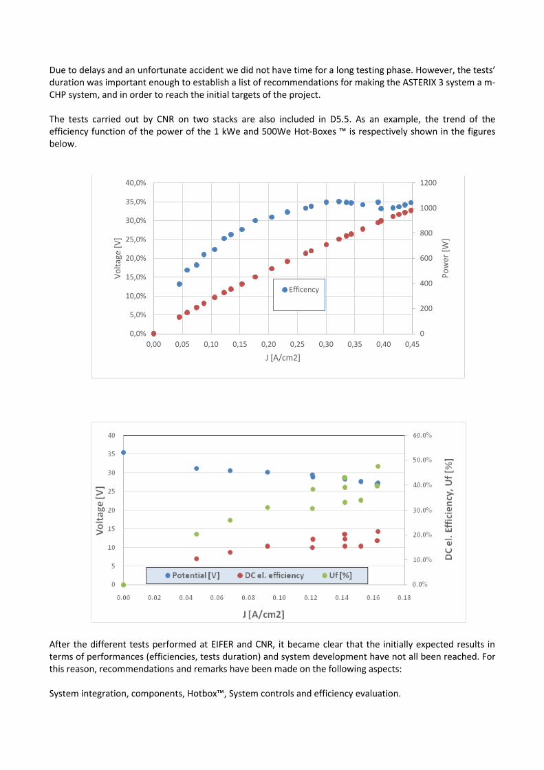
Due to delays and an unfortunate accident we did not have time for a long testing phase. However, the tests’ duration was important enough to establish a list of recommendations for making the ASTERIX 3 system a m-CHP system, and in order to reach the initial targets of the project. The tests carried out by CNR on two stacks are also included in D5.5. As an example, the trend of the efficiency function of the power of the 1 kWe and 500We Hot-Boxes ™ is respectively shown in the figures below.
After the different tests performed at EIFER and CNR, it became clear that the initially expected results in terms of performances (efficiencies, tests duration) and system development have not all been reached. For this reason, recommendations and remarks have been made on the following aspects: System integration, components, Hotbox™, System controls and efficiency evaluation.
0
200
400
600
800
1000
1200
0,0%
5,0%
10,0%
15,0%
20,0%
25,0%
30,0%
35,0%
40,0%
0,00 0,05 0,10 0,15 0,20 0,25 0,30 0,35 0,40 0,45
Po
wer
[W
]
Vo
ltag
e [V
]
J [A/cm2]
Efficency
