design, analysis and testing of the adeo …elib.dlr.de/111628/1/c1489886sinn.pdf · design,...
TRANSCRIPT

DESIGN, ANALYSIS AND TESTING OF THE ADEO PASSIVE DE-ORBIT SUBSYSTEM DEMONSTRATOR
Thomas Sinn (1), P. Seefeldt (3), A. Riemer (2), S. Meyer (4), T. Spröwitz (3), R. Hahn (2),
S. Reershemius(3), M. Zander (4), L. Tiedemann (1), K. D. Bunte (5), T. Cardone (6), D. Teti (6)
(1) HPS GmbH, Hofmannstr. 25-27, 81379, Munich, Germany, EMail: [email protected] (2) HTS GmbH, Am Glaswerk 6, 01640, Coswig, Germany, EMail: [email protected]
(3) DLR German Aerospace Center - Institute of Space Systems, Robert-Hooke-Str. 7, 28359, Bremen, Germany, EMail: [email protected]
(4) DLR German Aerospace Center - Institute of Composite Structures and Adaptive Systems, Lilienthalplatz 7, 38108, Brunswick, Germany, EMail: [email protected]
(5) etamax space GmbH, Frankfurter Straße 3d, 38122, Brunswick, Germany, EMail: [email protected]
(6) ESA/ESTEC, Keplerlaan, 1, 2201 AZ, Noordwijk, The Netherlands, EMail: [email protected]
ABSTRACT The space debris environment, especially in low earth orbit, is an increasing risk for all spaceflight missions. Without effective mitigation measures the debris density will increase to a level where spaceflight becomes more and more endangered. Therefore, to ensure safety for future space flight, end-of-life de-orbiting of satellites and upper stages is required by the respective standards. Deployable gossamer structures for drag sails might offer a passive de-orbit solution. The paper at hand outlines the development of such a system. It is based on the Gossamer-1 technology of the German Aerospace Center (DLR). The further development is pursued in the ESA project “Deployable Membrane” and “Architectural Design and Testing of a De-orbiting Subsystem” (ADEO). The ADEO subsystem is a drag augmentation device that uses the residual earth atmosphere present in low earth orbit. For initiation of the de-orbit manoeuvre a large surface is deployed which multiplies the drag effective surface of the satellite. Thereby the drag force is increased as well causing accelerated decay in orbit altitude. Advantageous about a drag augmentation device is that it does not require any active steering and can be designed for passive attitude stabilization. Thereby it is also applicable for non-operational, tumbling spacecraft. The ADEO subsystem consists of four coilable carbon fiber reinforced polymer (CFRP) booms that span four sail segments in a truncated pyramid shape configuration. The sail membrane is made of an aluminium coated polyimide foil. The coating thickness was chosen such that it provides sufficient protection from the space environment. The sail provides a 25m2 area spanned in a pyramidal form that is enabling passive drag attitude stabilization. The here presented work includes a detailed design of the ADEO system, complemented by an environment analysis, and the results from critical breadboard testing. Currently a fully functional demonstrator is being built. The demonstrator will be subjected to environmental testing including deployment testing in thermal-vacuum environment and ambient conditions in October 2016.
1. INTRODUCTION The space debris environment especially in the low earth orbit is an increasing risk for all spaceflight missions. Without effective mitigation measures the debris density will increase to a level where spaceflight becomes more and more endangered. Especially collision fragments will

become a dominant part in the debris population larger than 1 cm. Therefore, to ensure safety for future space flight, end-of-life de-orbiting of satellites and upper stages is necessary [1]. For the de-orbiting of satellites in the low earth orbit using an on-board de-orbiting device, several concepts are applicable. They are based either on a propulsion system or on interaction with natural phenomena in the low earth orbit. If a satellite utilises a propulsion system it can be an advantage that only additional propellant needs to be added to perform a de-orbit manoeuvre. Considering that the propulsion system must work at End-of-life (EOL) this advantage can also turn into a disadvantage with respect to its reliability. For satellites that do not have an adequate propulsion system and to ensure that a reliable de-orbit can be performed an independent de-orbit module should be considered, either as main de-orbit solution or as a backup system to ensure a redundancy for the de-orbitation. The ADEO project presented here relies on the utilization of the natural drag decay in low earth orbit by increasing the drag area of the satellite at (EOL). Drag augmentation devices (sometimes referred to as Drag Sail) are using the residual earth atmosphere present in the low earth orbit [1], [2]. For initiation of the de-orbit manoeuvre a large surface is deployed which multiplies the drag effective surface of the satellite. Thereby the drag force is increased as well causing accelerated decay in orbit altitude. Advantageous about a drag augmentation device is that it does not require any active steering and can be designed for passive attitude stabilization. Thereby it is also applicable for non-operational, tumbling spacecraft. In order to accelerate the natural orbit decay the drag area needs to be increased without significantly increasing the mass of the satellite. It is therefore necessary to deploy a very light-weight sail at EOL of the satellite. This kind of structures is known as gossamer structures. The development of deployable membrane structures in Europe and for instance at the German Aerospace Center (DLR) goes back to the 1990s when the first 20m x 20m solar sail breadboards were tested in a joint DLR, NASA/JPL and ESA project, followed by several development projects like ODISSEE [3] and GEOSAIL [4]. The ground demonstration is presented in [5] and the study activities are summarized in [6]. Based on those previous projects, DLR recently developed scalable deployment technology for gossamer spacecraft systems in the Gossamer-1 project presented in [7]. While a focus was on solar sailing and thin-film photovoltaics the aim of the development is to provide scalable and reliable technology for deployable membrane structures for various space applications. An artist impression of the Gossamer-1 is given in Fig. 1.
Fig. 1: DLR’s Gossamer-1 artists impression.
Within the ESA projects Deployable Membrane and ADEO the Gossamer-1 technology is adapted and further developed for the drag sail application. The sail system utilizes CFRP booms and coated polyimide foils. In contrast to the previous development the ADEO system design aims for passive
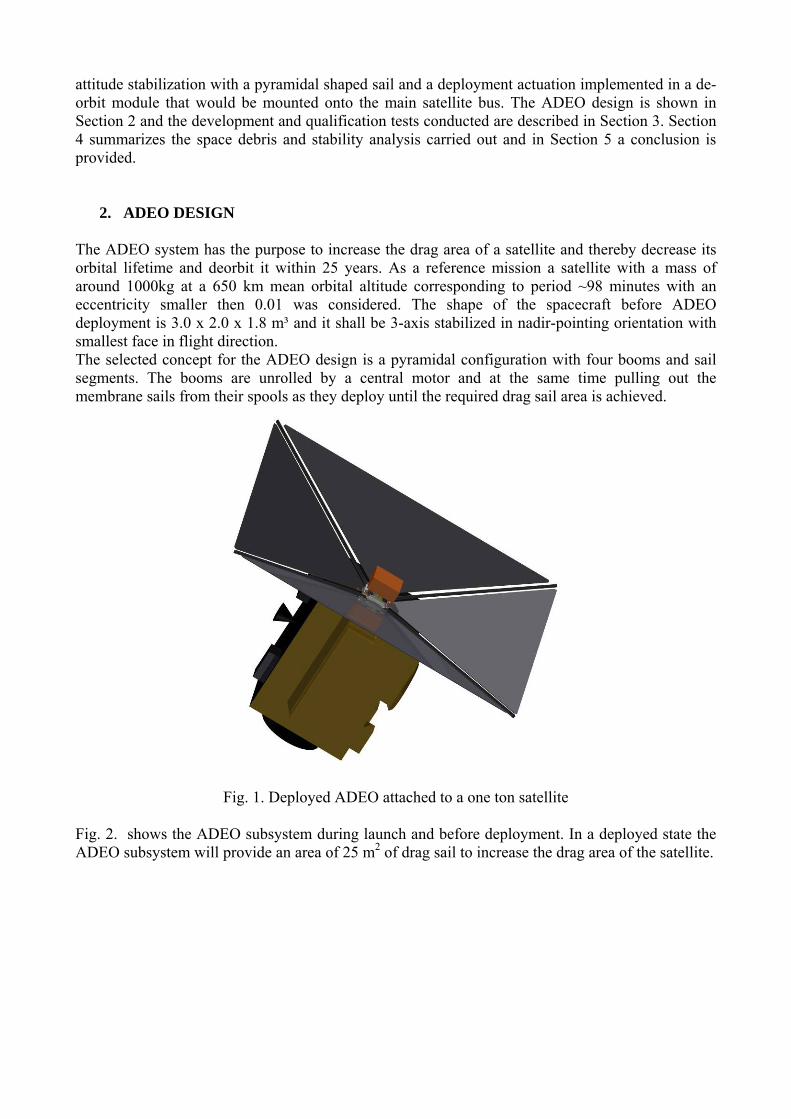
attitude stabilization with a pyramidal shaped sail and a deployment actuation implemented in a de-orbit module that would be mounted onto the main satellite bus. The ADEO design is shown in Section 2 and the development and qualification tests conducted are described in Section 3. Section 4 summarizes the space debris and stability analysis carried out and in Section 5 a conclusion is provided.
2. ADEO DESIGN The ADEO system has the purpose to increase the drag area of a satellite and thereby decrease its orbital lifetime and deorbit it within 25 years. As a reference mission a satellite with a mass of around 1000kg at a 650 km mean orbital altitude corresponding to period ~98 minutes with an eccentricity smaller then 0.01 was considered. The shape of the spacecraft before ADEO deployment is 3.0 x 2.0 x 1.8 m³ and it shall be 3-axis stabilized in nadir-pointing orientation with smallest face in flight direction. The selected concept for the ADEO design is a pyramidal configuration with four booms and sail segments. The booms are unrolled by a central motor and at the same time pulling out the membrane sails from their spools as they deploy until the required drag sail area is achieved.
Fig. 1. Deployed ADEO attached to a one ton satellite
Fig. 2. shows the ADEO subsystem during launch and before deployment. In a deployed state the ADEO subsystem will provide an area of 25 m2 of drag sail to increase the drag area of the satellite.

Fig. 2. ADEO Launch Configuration (left) and Deployed Configuration (right)
These 25 m2 of foil are separated in four equal triangular membranes. These membranes are folded and coiled around four membrane spools which are located on each of the sides of ADEO. The membrane will be deployed by using CFRP booms with a double omega cross sectional profile and therefore a stable configuration once deployed. The four CFRP booms expand diagonally from the corners of the ADEO subsystem throughout the corners of the sails they are attached to once they are deployed.
Fig. 3. ADEO subsystem without cover
The booms and the membranes are protected by one overall cover during launch and during in-orbit storage. Once the time for deployment initiation has come, the cover will be lifted by guided springs triggered by a pin puller hold down release mechanism in the centre of ADEO. Within the cover also the launch locks for the boom and membrane spools are removed. A motor is used to push out the booms through guide-rails to initiate sail deployment.
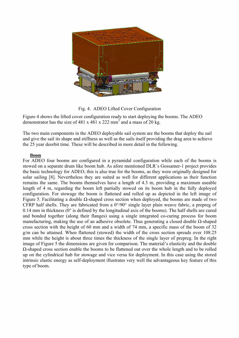
Fig. 4. ADEO Lifted Cover Configuration
Figure 4 shows the lifted cover configuration ready to start deploying the booms. The ADEO demonstrator has the size of 481 x 481 x 222 mm3 and a mass of 20 kg. The two main components in the ADEO deployable sail system are the booms that deploy the sail and give the sail its shape and stiffness as well as the sails itself providing the drag area to achieve the 25 year deorbit time. These will be described in more detail in the following.
Boom For ADEO four booms are configured in a pyramidal configuration while each of the booms is stowed on a separate drum like boom hub. As afore mentioned DLR´s Gossamer-1 project provides the basic technology for ADEO, this is also true for the booms, as they were originally designed for solar sailing [8]. Nevertheless they are suited as well for different applications as their function remains the same. The booms themselves have a length of 4.3 m, providing a maximum useable length of 4 m, regarding the boom left partially stowed on its boom hub in the fully deployed configuration. For stowage the boom is flattened and rolled up as depicted in the left image of Figure 5. Facilitating a double Ω-shaped cross section when deployed, the booms are made of two CFRP half shells. They are fabricated from a 0°/90° single layer plain weave fabric, a prepreg of 0.14 mm in thickness (0° is defined by the longitudinal axis of the booms). The half shells are cured and bonded together (along their flanges) using a single integrated co-curing process for boom manufacturing, making the use of an adhesive obsolete. Thus generating a closed double Ω-shaped cross section with the height of 60 mm and a width of 74 mm, a specific mass of the boom of 32 g/m can be attained. When flattened (stowed) the width of the cross section spreads over 108.25 mm while the height is about three times the thickness of the single layer of prepreg. In the right image of Figure 5 the dimensions are given for comparison. The material’s elasticity and the double Ω-shaped cross section enable the booms to be flattened out over the whole length and to be rolled up on the cylindrical hub for stowage and vice versa for deployment. In this case using the stored intrinsic elastic energy as self-deployment illustrates very well the advantageous key feature of this type of boom.

Fig. 5. CFRP boom of DLR partially stowed (left); Cross sectional boom dimensions (right) Membrane The entire drag sail will consist of four single, triangular membranes, shaped to fit with the pyramidal design of the deployed ADEO system. Particular emphasis lays on the rough environmental effects and low storage volume in combination with a smooth deployment behaviour. In order to withstand the environmental effects such as thermal cycles, Atomic Oxygen exposure, Ultra Violet radiation, space debris and micrometeorite impacts, multiple material combinations have been assessed and partially tested in a dedicated ESA project. Upilex S, a 12.5 μm thick Polyimide film, coated with 500 nm aluminium is evaluated as the most suitable Material to withstand the 15 years storage and 25 years deployed in orbit. The Membrane material did undergo a test campaign where its behaviour to thermal cycles between -80°C to 220 °C, 20 years Atomic Oxygen exposure and one year Ultra Violet radiation has been tested. Additionally, impact tests were performed with particle velocities up to 4 km/s at the Technical University of Munich. Post tests assessments, such as thermo-optical properties measurements, strength and stiffness tests as well as microscopic inspections are currently performed to determine the degradation effects to the material properties. Crack propagation as a result of space debris or micrometeorites impacts has been assessed, tested and, based on the test results, analyzed so that a sufficient crack stopper system can be applied to the Membrane. Therefore, the strength distribution is analyzed taking into account local buckling effects (see Figure 6).
Fig. 6. Main strength S1/Nmm-² and S2/Nmm-²

In parallel, folding and storage concepts have been evaluated as shown in Figure 7. One dimensional folding of sail segments is the most frequently considered stowing strategy for triangular sail segments. Coiling of the segments ensures a smooth and controllable deployment behaviour. Two types of Zig-Zag folding have been developed, depending on the Membrane Spools arrangement of the in the ADEO system. Based on the horizontal spool alignment, Zig-Zag folding, parallel to the height of the membrane is evaluated as the most suitable storing strategy. Figure 8 provides an impression of the storing procedure where one segment of the sail is folded and coiled onto the spool.
Fig. 7. Overview of considered stowing strategies with the chosen ADEO strategy highlighted in
green.
Fig. 8. Packaging of the Membrane folded parallel to the height and coiled onto the spool

3. TESTING Several Tests were conducted on component level and tests of the complete deployment system are currently under preparation. Breadboards of the boom and boom related mechanisms were tested. It included pull of tests in order to establish a force budget of the boom deployment as well as high velocity impact and creep tests. The membrane related tests were part of the Deployable Membrane project. It included environmental testing of the membrane material, for instance its resistance against atomic oxygen and UV-radiation, as well as deployment tests employing the deployment test facility at DLR’s Institute of Space Systems. Test strategy for gossamer systems has been established according to a test-as-you-fly approach [7],[9]. Sail Functionality Tests The membrane spool breadboard tests had the purpose to validate the functionality of the membrane unspooling device as well as to obtain the necessary pull out forces for the motor selection. Furthermore, a sinusoidal and random vibration test was carried out to verify the use of journal bearings. Figure 9 shows the test setup for the measurement of the pull-off force before and after vibration testing. The force measurement shows that there is no change in the mechanical behaviour of the bearing due to the vibration loads.
Fig. 9. Measurement of pull- off force (without spool brake).
After the verification of the spool bread board, it was used to subject the membrane to a full test campaign (see Fig. 10) employing the test facilities of DLR’s Institute of Space Systems. For the requirements verification the dimensions of the stowed membrane were measured and the membrane was visually checked for damage.
Fig. 10. Test flow for the membrane and demonstrator testing.
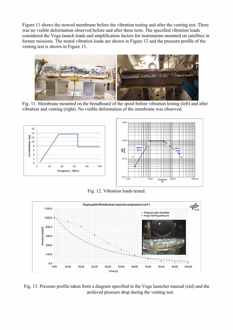
Figure 11 shows the stowed membrane before the vibration testing and after the venting test. There was no visible deformation observed before and after these tests. The specified vibration loads considered the Vega launch loads and amplification factors for instruments mounted on satellites in former missions. The tested vibration loads are shown in Figure 12 and the pressure profile of the venting test is shown in Figure 13.
Fig. 11. Membrane mounted on the breadboard of the spool before vibration testing (left) and after vibration and venting (right). No visible deformation of the membrane was observed.
Fig. 12. Vibration loads tested.
Fig. 13. Pressure profile taken from a diagram specified in the Vega launcher manual (red) and the archived pressure drop during the venting test.

After the vibration and venting test a laboratory deployment with a measurement of the deployment forces was carried out (see Figure 14). Two linear drive units were arranged at an angle of 89° according to the opening angle of the boom. The outer interfaces of the sail segment were attached to three-axis force sensors mounted on the drive units. The segment was deployed with a speed of 3.9 mm/s. Figure 15 shows the measured total forces. They correspond to the expected forces required to overcome the brake torque of the spool. With progressing deployment an unavoidable impact of gravity loads leads to an increase of the forces. At the beginning a clamping during the interface release appeared. This problem is now solved by an adequate interface design and guidance of the ADEO demonstrator.
Fig. 14. Deployment test in progress.
Fig. 15. Deployment force measured on both outer interfaces of the segment that were pulled off of
the sail spool by the linear drive units. Boom Functionality & Mechanical Boom Loading Tests The boom spool breadboard tests had the purpose to validate the functionality of the boom deployment device as well as to obtain the necessary pull out forces for the motor selection and to validate the occurring loads on the booms in the ADEO configuration. Furthermore, a sinusoidal and random vibration test was carried out to verify the use of journal bearings. Further tests on the boom deployment as well as mechanical boom loading were performed. These tests are performed

in order to determine the required belt force for deploying the boom and to determine the maximum forces possible acting on the boom during deployment and in deployed configuration. All tests are performed with the same pretension on the boom spool brake. During deployment the boom displacement as well as the belt force is measured. In Figure 16 the boom spool breadboard is shown before and after boom deployment in the boom test stand of DLR Braunschweig.
Fig.16. Boom spool breadboard before (left) and after (right) boom deployment
The mechanical boom loading (bending) tests were performed at different free length with the according angles of attack, starting with the largest length in order to roll in possibly occurring damages throughout the test program. By applying an asymmetric load onto the boom, this test series generated values for a worst case scenario, when the load of only one sail quadrant adjacent to the boom is acting on it. Creep Test The boom creep test had the purpose to investigate the creep behaviour of the booms when stored for longer time at reduced and elevated temperatures. The dependency of the plastic deformation of the CFRP material on stowage time, temperature and up-reeling radii is here investigated. More specifically, the test shall deliver measurements of the straightness of the specimens after held in a curved set up for elongated time. A complete description of the creep testing, its procedure and results is given in a separate paper [10]. Boom Impact Tests The boom impact tests had the purpose to investigate the load carrying capability of the boom elements when subjected to a space debris impact. The test facility for the impact test was the electrothermal accelerator at the Institute of Astronautics, University of Munich, Germany. The impact object is a nylon cylinder of diameter Ø4 mm and length 2 mm. The impact velocity was in the order of ~4 km/sec.
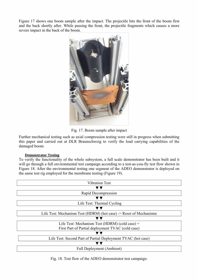
Figure 17 shows one boom sample after the impact. The projectile hits the front of the boom first and the back shortly after. While passing the front, the projectile fragments which causes a more severe impact in the back of the boom.
Fig. 17. Boom sample after impact
Further mechanical testing such as axial compression testing were still in progress when submitting this paper and carried out at DLR Braunschweig to verify the load carrying capabilities of the damaged boom.
Demonstrator Testing To verify the functionality of the whole subsystem, a full scale demonstrator has been built and it will go through a full environmental test campaign according to a test-as-you-fly test flow shown in Figure 18. After the environmental testing one segment of the ADEO demonstrator is deployed on the same test rig employed for the membrane testing (Figure 19).
Vibration Test
Rapid Decompression
Life Test: Thermal Cycling
Life Test: Mechanism Test (HDRM) (hot case) -> Reset of Mechanisms
Life Test: Mechanism Test (HDRM) (cold case) + First Part of Partial deployment TVAC (cold case)
Life Test: Second Part of Partial Deployment TVAC (hot case)
Full Deployment (Ambient)
Fig. 18. Test flow of the ADEO demonstrator test campaign.
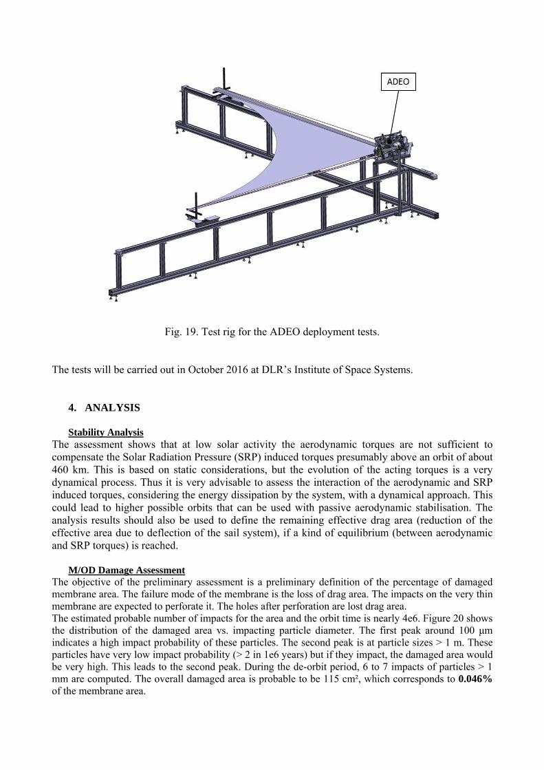
Fig. 19. Test rig for the ADEO deployment tests.
The tests will be carried out in October 2016 at DLR’s Institute of Space Systems.
4. ANALYSIS Stability Analysis The assessment shows that at low solar activity the aerodynamic torques are not sufficient to compensate the Solar Radiation Pressure (SRP) induced torques presumably above an orbit of about 460 km. This is based on static considerations, but the evolution of the acting torques is a very dynamical process. Thus it is very advisable to assess the interaction of the aerodynamic and SRP induced torques, considering the energy dissipation by the system, with a dynamical approach. This could lead to higher possible orbits that can be used with passive aerodynamic stabilisation. The analysis results should also be used to define the remaining effective drag area (reduction of the effective area due to deflection of the sail system), if a kind of equilibrium (between aerodynamic and SRP torques) is reached. M/OD Damage Assessment The objective of the preliminary assessment is a preliminary definition of the percentage of damaged membrane area. The failure mode of the membrane is the loss of drag area. The impacts on the very thin membrane are expected to perforate it. The holes after perforation are lost drag area. The estimated probable number of impacts for the area and the orbit time is nearly 4e6. Figure 20 shows the distribution of the damaged area vs. impacting particle diameter. The first peak around 100 μm indicates a high impact probability of these particles. The second peak is at particle sizes > 1 m. These particles have very low impact probability (> 2 in 1e6 years) but if they impact, the damaged area would be very high. This leads to the second peak. During the de-orbit period, 6 to 7 impacts of particles > 1 mm are computed. The overall damaged area is probable to be 115 cm², which corresponds to 0.046% of the membrane area.
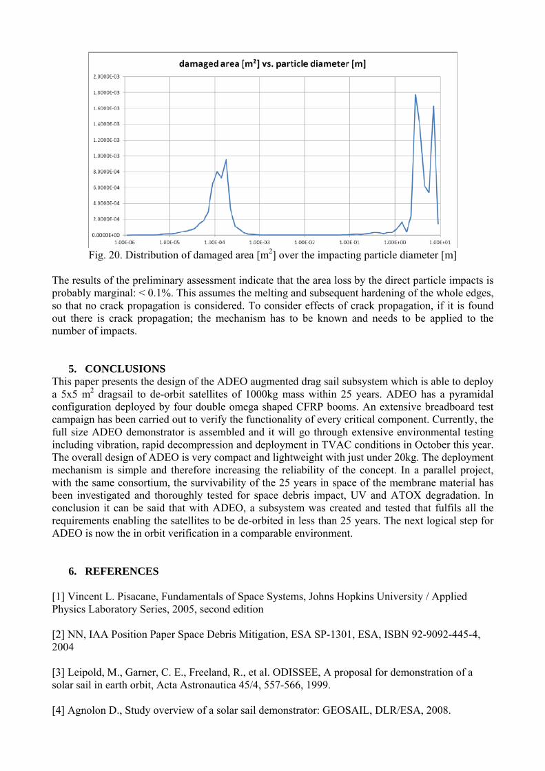
Fig. 20. Distribution of damaged area [m2] over the impacting particle diameter [m]
The results of the preliminary assessment indicate that the area loss by the direct particle impacts is probably marginal: < 0.1%. This assumes the melting and subsequent hardening of the whole edges, so that no crack propagation is considered. To consider effects of crack propagation, if it is found out there is crack propagation; the mechanism has to be known and needs to be applied to the number of impacts.
5. CONCLUSIONS
This paper presents the design of the ADEO augmented drag sail subsystem which is able to deploy a 5x5 m2 dragsail to de-orbit satellites of 1000kg mass within 25 years. ADEO has a pyramidal configuration deployed by four double omega shaped CFRP booms. An extensive breadboard test campaign has been carried out to verify the functionality of every critical component. Currently, the full size ADEO demonstrator is assembled and it will go through extensive environmental testing including vibration, rapid decompression and deployment in TVAC conditions in October this year. The overall design of ADEO is very compact and lightweight with just under 20kg. The deployment mechanism is simple and therefore increasing the reliability of the concept. In a parallel project, with the same consortium, the survivability of the 25 years in space of the membrane material has been investigated and thoroughly tested for space debris impact, UV and ATOX degradation. In conclusion it can be said that with ADEO, a subsystem was created and tested that fulfils all the requirements enabling the satellites to be de-orbited in less than 25 years. The next logical step for ADEO is now the in orbit verification in a comparable environment.
6. REFERENCES
[1] Vincent L. Pisacane, Fundamentals of Space Systems, Johns Hopkins University / Applied Physics Laboratory Series, 2005, second edition [2] NN, IAA Position Paper Space Debris Mitigation, ESA SP-1301, ESA, ISBN 92-9092-445-4, 2004 [3] Leipold, M., Garner, C. E., Freeland, R., et al. ODISSEE, A proposal for demonstration of a solar sail in earth orbit, Acta Astronautica 45/4, 557-566, 1999. [4] Agnolon D., Study overview of a solar sail demonstrator: GEOSAIL, DLR/ESA, 2008.

[5] Leipold, M, Eiden, M., Garner, C. E., et al., Solar sail technology development and demonstration, Acta Astronautica 52/2, 317-326, 2003. [6] Leipold M., Widani C., Groepper P., et al. The European Solar Sail Deployment Demonstrator Mission, Proceedings of the International Astronautical Congress, 2006. [7] Seefeldt, P., Spiez, P., Spröwitz, T. et al., Gossamer-1: Mission Concept and Technology for a Controlled Deployment of Gossamer Spacecraft, Advances in Space Research, 2016 (submitted and under review) [8] Straubel, M., Zander, M.E., and Hühne C., Design and Sizing of the GOSSAMER Boom Deployment Concept. In Malcolm Macdonald, editor, Advances in Solar Sailing, Springer Praxis Books, chapter Part III Technology Activities, pages 593 – 608. Springer-Verlag, 2014. [9] Seefeldt, P, Steindorf L., and Spröwitz T.. Solar Sail Membrane Testing and Design Considerations, European Conference on Spacecraft Structures, Materials and Mechanical Testing. 2014. [10] Meyer, S., Zander, M.E., and Hühne C., Preliminary Creep Test for estimating the long term stowage behaviour of DLR’s CFRP booms, In ECSSMET 2016 - European Conference on Spacecraft Structures, Materials & Environmental Testing, Toulouse, France, 27-30 September 2016 , CNES/ESA/DLR.