design & analysis of gate valve dn900 #150 -...
TRANSCRIPT
International Journal of Innovations in Engineering and Technology (IJIET) http://dx.doi.org/10.21172/ijiet.83.019
Volume 8 Issue 3 June 2017 130 ISSN: 2319-1058
Design & Analysis of Gate valve DN900 #150 Tausif Ahmed Kundagol
Department of Machine Design Akshaya Institute of Technology, Tumakuru, Karnataka, India Affiliated to Visvesvaraya Technological University, Belagavi
Dr.Irfan G BE., M.Tech, Ph.D., M.I.S.I.T.E.
Akshaya Institute of Technology, Tumakuru, Karnataka, India Affiliated to Visvesvaraya Technological University, Belagavi
Lohitesh jaga Kumar BE., M.Tech, M.I.S.I.T.E.
Akshaya Institute of Technology, Tumakuru, Karnataka, India Affiliated to Visvesvaraya Technological University, Belagavi
Abstract- Gate valve have industry leading shutoff and low maintenance performance designed for high pressure and high temperature conditions. Gate valves serves as efficient stop valve with flow in either direction. They are commonly used where minimum pressure drop is important. Throttling is not recommended because partially open gate valves exhibit flow characteristic not conducive to accurate and consistent flow control. Also the valve may be damaged due to high velocity across the seat. The function best suits for fully open of fully closed condition.
In this paper, Gate valve DN900 x 150 is designed and then analyzed using Simulation software for agreeable results.
I. INTRODUCTION Gate valves play an important role in today’s generation. You can see valves from household to some big industries. The function of valves is to control the flow, pressure, velocity and direction of liquids. The size range of gate valve includes DN50 – DN1000 of class 150, 300 & 600 respectively. In this paper we are concentrating on the Design of DN 900 class 150 which is as per API and relevant ASME B16.5, ASME B16.34 standards.
A. Salient Features Flexible Wedge Bolted bonnet construction Suitable for higher temperature
International Journal of Innovations in Engineering and Technology (IJIET) http://dx.doi.org/10.21172/ijiet.83.019
Volume 8 Issue 3 June 2017 131 ISSN: 2319-1058
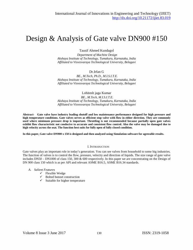
Figure 1. Cross sectional drawing of gate valve
The rest of the paper is organized as follows. Proposed theoretical calculation of body, wedge are explained in
section II. Experimental results are presented in section III. Concluding remarks are given in section IV.
II. PROPOSED THEORITCAL CALCULATION OF GATE VALVE
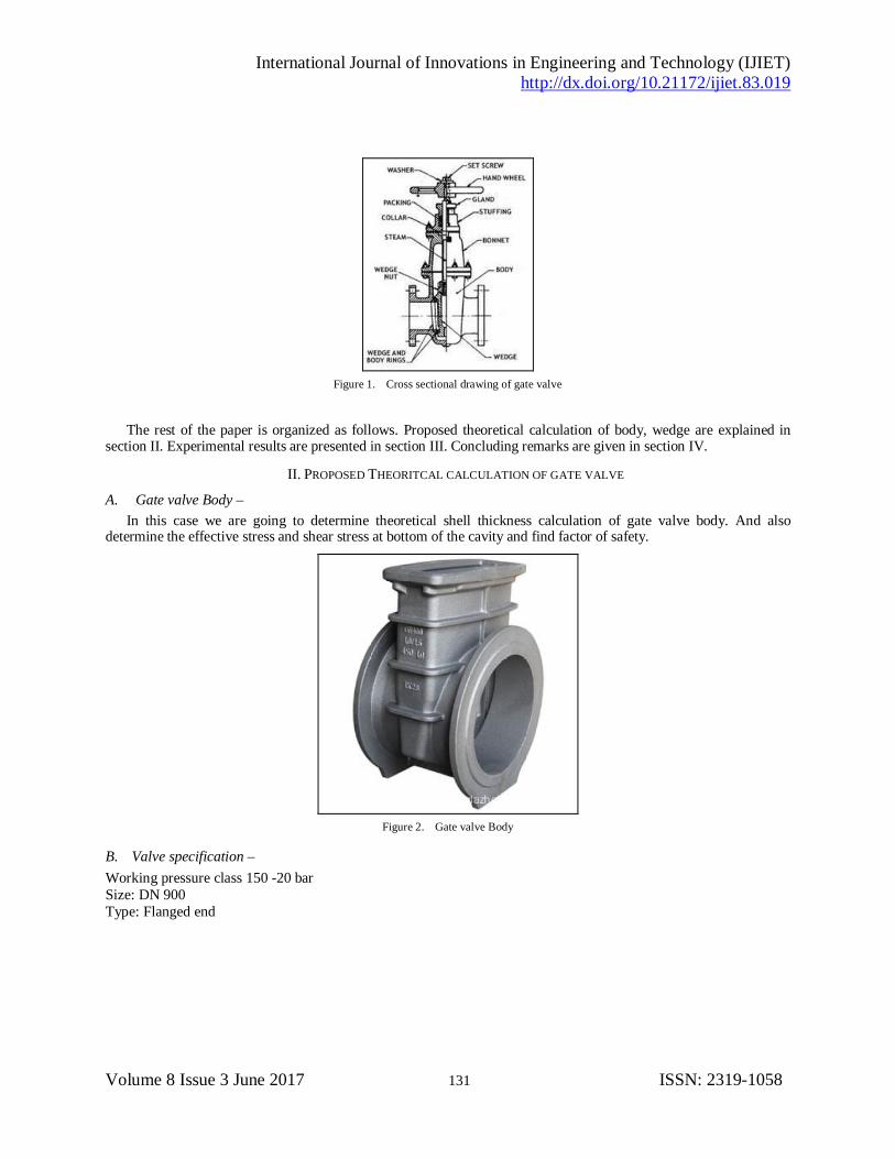
A. Gate valve Body – In this case we are going to determine theoretical shell thickness calculation of gate valve body. And also
determine the effective stress and shear stress at bottom of the cavity and find factor of safety.
Figure 2. Gate valve Body
B. Valve specification – Working pressure class 150 -20 bar Size: DN 900 Type: Flanged end

International Journal of Innovations in Engineering and Technology (IJIET) http://dx.doi.org/10.21172/ijiet.83.019
Volume 8 Issue 3 June 2017 132 ISSN: 2319-1058
C. Shell thickness calculation – Thin Cylinder concept:
Where p=Hydrostatic test pressure 2.95 N/mm^2 di = Maximum inside diamter of valve body casting (876mm) σa1=Maximum allowable stress 161 N/mm2 (For WCB Material) Substituting we get., t = (2.95*876) / (2*161) t = 8 mm As per ASME B16.34:
d = Maximum inside diamter of valve body casting (876mm) Substituting we get., t= 0.0163*876 + 4.7 t=19 mm As per ASME SEC VIII:
Where p=Hydrostatic test pressure 2.95 N/mm^2 di = Maximum inside diamter of valve body casting (876mm) σa1=Maximum allowable stress 161 N/mm2 (For WCB Material) ηeff = joint efficiency is one Substituting we get., t = (2.95*876)/(2*(161*1-(0.6*2.95))) t = 8.1 mm

International Journal of Innovations in Engineering and Technology (IJIET) http://dx.doi.org/10.21172/ijiet.83.019
Volume 8 Issue 3 June 2017 133 ISSN: 2319-1058
D. Stress Analysis:
Longitudinal wall stress:
Where p=Hydrostatic test pressure 2.95N/mm^2 di = Maximum inside diamter of valve body casting (876mm) t= shell thickness including allowance (28mm) σl=longitudinal stress in the body σl=(2.95*876)/(4*28) σl=23.1N/mm2 Tangential wall stress of the body:
σt = (2.95*876)/(2*28) σt= 46.1N/mm2 Radial wall stress of the body:
σr= -2.95 N/mm2 Effective stress in a body:
Max Stress 49.1 N/mm2
E. Determine the Bearing Stress and Shear Stress at the weaker section of the Gate. Bearing Stress at the base of Flexible Wedge Gate:

International Journal of Innovations in Engineering and Technology (IJIET) http://dx.doi.org/10.21172/ijiet.83.019
Volume 8 Issue 3 June 2017 134 ISSN: 2319-1058
Where, ∆p= pressure drop when wedge is completely closed. Di=inner seating diameter d= bore diamter of valve body σbase= (13.78*876^2)/(876^2) σbase=13.78 N/mm2 Shear Stress at the bottom cavity:
Where, ∆p= pressure drop when wedge is completely closed. Di=inner seating diameter d= bore diamter of valve body tgate= minimum thickness of gate tbase = 13.78*(0.785*876^2)/(3.142*876*75) tbase = 40.2 N/mm2
Figure 3. Drawing reference for wedge of gate valve

International Journal of Innovations in Engineering and Technology (IJIET) http://dx.doi.org/10.21172/ijiet.83.019
Volume 8 Issue 3 June 2017 135 ISSN: 2319-1058
III. RESULT AND DISCUSSION As per industry norms displacement must be within 2000 microns. Since the size is larger and displacement
obtained from analysis is 1290 microns at 30 bar pressure & 232 microns at 20 bar pressure. Hence it is within the permissible limits.
Factor of safety (FOS): Yield strength/Allowable stress
FOS : 248/181 = 1.37
(a)
(b)
Figure 4. (a) Stress behaviour of body (b) Deformation of body
Wedge Analysis:
As per industry norms displacement must be within 2000 microns. Since the size is larger and displacement obtained from analysis is 200 microns and induced stress is 181 Mpa. Hence it is within the permissible limits.
Factor of safety (FOS): Yield strength/Allowable stress
FOS : 248/181 = 1.37

International Journal of Innovations in Engineering and Technology (IJIET) http://dx.doi.org/10.21172/ijiet.83.019
Volume 8 Issue 3 June 2017 136 ISSN: 2319-1058
(a)
(b)
Figure 5. (a) Stress behaviour of body (b) Deformation of body
IV.CONCLUSION The components used in gate valves DN900 x 150 are modeled, detailed and analyzed for the given pressure,
using software package solid works and solid works simulation. This models are theoretically calculated and analyzed whether the design is safe or not using relevant standards like ASME SEC VIII, ASME SEC II Part D, and relevant API standards. The overall design was cross checked with cross functional team and approved for prototype and production
Along with the summary analysis the von mises stress and displacement was found to be suitable for working conditions.

International Journal of Innovations in Engineering and Technology (IJIET) http://dx.doi.org/10.21172/ijiet.83.019
Volume 8 Issue 3 June 2017 137 ISSN: 2319-1058
REFERENCE
[1] Philip.L.Skousen,Valve Hand bookJ.K. emplay CEng,FIMeche, valves hand book by DANTE D ORAZIO solid works software bible by DASSAULT systems.
[2] Valve selection hand book by R.W.ZAPPE [3] The design of valves and fittings by G.H.PEARSON [4] Hand book of VALVES AND ACTUATORS by BRAIN NESBITT Standard refer API 594, ASME B16, ASTM A126 [5] Design Data Hand Book 3rd Edition by K.Mahadevan & K.Balaveera Reddy, 2010 [6] Design of machine elements II by Prof. J.B.K. Das and P.L. Srinivasa Murthy, Sapna book house (P) Ltd., 2010 [7] Pavol, R., D. Kumar, S. Csaba, M. Neil and C. Rey, 2008. Modeling and measurement of granule attrition during pneumatic conveying in a
laboratory scale system, Powder Technology, 185: 202-210. [8] Hazem I. Ali, Samsul Bahari B Mohd Noor, S. M. Bashi, M. H. Marhaban , A Review of Pneumatic Actuators (Modeling and Control),
Australian Journal of Basic and Applied Sciences, 3(2): 440-454, 2009 [9] Roark’s Formulas for Stress and Strain WARREN C. YOUNG RICHARD G. BUDYNAS, McGraw-Hill, Seventh Edition, 2002. [10] Shigley’s Mechanical Engineering Design, McGraw-Hill, Eighth Edition, 2006 [11] ASME Sec II part D material properties ,ASME,Publish date 2015 [12] Tanveer Ahamed Bankapur,Lohitesh Jaga Kumar,Dr.Irfan G,“Design and Analysis of Dual plate Check Valve”,IJIET volume 07, Issue
01,June 2016,pp 422-426