design and aircraft systems - download.e-bookshelf.de · contents vii 4.3 design drivers in the...
TRANSCRIPT
Aerospace SeriesEditors Peter Belobaba, Jonathan Cooper,
Roy Langton and Allan Seabridge
Ian Moir and Allan Seabridge
Design and Development of Aircraft SystemsSecond Edition
Red box Rules aRe foR pRoof stage only. delete befoRe final pRinting.
In the second edition of Design and Development of Aircraft Systems, Ian Moir and Allan Seabridge provide a straightforward introduction to how aircraft systems are designed and evolved; explaining to the reader the means by which the systems of a complex aircraft emerge from a customer requirement and become reality as individual sub-systems; an integrated overall system; and a complete fit-for-purpose aircraft. This edition has been updated with extensive new material on unmanned air vehicles, together with updates to all chapters to bring them in line with current design practice and technologies.
For many engineers, the design and development activity takes place at a single domain level – the fuel system, the hydraulic system, flight control system, etc. Increasingly, however, there is a need to consider how these domains integrate into the bigger picture: for example, the engineer designing the display system will need to consider the entire weapons system. Concentrating on the product life cycle, the design and development process, and the skills required to develop a product as complex as an aircraft, Design and Development of Aircraft Systems, Second Edition is a book for people who want to understand how industry develops a fully integrated, tested, and qualified product that is safe to fly and fit for purpose.
Key features:• Provides a holistic view of aircraft system design describing the interaction between all
subsystems such as fuel systems, navigation, flight control, etc.• Covers all aspects of design including systems engineering; design drivers; systems
architectures; systems integration; modelling of systems; practical considerations and systems examples.
• Incorporates essential new material on Unmanned Aircraft Systems (UAS).
Commercial and military aerospace engineers, designers, operators, maintenance crew and those studying to become part of the aerospace industry will find Design and Development of Aircraft Systems, Second Edition an invaluable resource.
Ian MoirMoir Associates
Allan SeabridgeAerospace Systems Consultant
Design and Development of Aircraft SystemsSecond Edition
Second Edition
Moir
SeabridgeD
esign and Developm
ent of A
ircraft Systems

DESIGN ANDDEVELOPMENT OFAIRCRAFT SYSTEMS
Aerospace Series List
Understanding Aerodynamics: Arguing from theReal Physics
McLean November 2012
Introduction to UAV Systems, 4th Edition Fahlstrom and Gleason August 2012Theory of Lift: Introductory Computational
Aerodynamics with MATLAB and OctaveMcBain August 2012
Sense and Avoid in UAS: Research andApplications
Angelov April 2012
Morphing Aerospace Vehicles and Structures Valasek April 2012Gas Turbine Propulsion Systems MacIsaac and Langton July 2011Basic Helicopter Aerodynamics, 3rd Edition Seddon and Newman July 2011Advanced Control of Aircraft, Spacecraft and
RocketsTewari July 2011
Cooperative Path Planning of Unmanned AerialVehicles
Tsourdos et al November 2010
Principles of Flight for Pilots Swatton October 2010Air Travel and Health: A Systems Perspective Seabridge et al September 2010Design and Analysis of Composite Structures:
With applications to aerospace StructuresKassapoglou September 2010
Unmanned Aircraft Systems: UAVS Design,Development and Deployment
Austin April 2010
Introduction to Antenna Placement &Installations
Macnamara April 2010
Principles of Flight Simulation Allerton October 2009Aircraft Fuel Systems Langton et al May 2009The Global Airline Industry Belobaba April 2009Computational Modelling and Simulation of
Aircraft and the Environment: Volume 1 -Platform Kinematics and SyntheticEnvironment
Diston April 2009
Handbook of Space Technology Ley, Wittmann Hallmann April 2009Aircraft Performance Theory and Practice for
PilotsSwatton August 2008
Surrogate Modelling in Engineering Design: APractical Guide
Forrester, Sobester, Keane August 2008
Aircraft Systems, 3rd Edition Moir & Seabridge March 2008Introduction to Aircraft Aeroelasticity And Loads Wright & Cooper December 2007Stability and Control of Aircraft Systems Langton September 2006Military Avionics Systems Moir & Seabridge February 2006Design and Development of Aircraft Systems Moir & Seabridge June 2004Aircraft Loading and Structural Layout Howe May 2004Aircraft Display Systems Jukes December 2003Civil Avionics Systems Moir & Seabridge December 2002
DESIGN ANDDEVELOPMENT OFAIRCRAFT SYSTEMSSECOND EDITION
Ian MoirMoir Associates
Allan SeabridgeAerospace Systems Consultant
A John Wiley & Sons, Ltd., Publication

This edition first published 2013C© 2013 John Wiley & Sons, Ltd
Registered officeJohn Wiley & Sons Ltd, The Atrium, Southern Gate, Chichester, West Sussex, PO19 8SQ, United Kingdom
For details of our global editorial offices, for customer services and for information about how to apply forpermission to reuse the copyright material in this book please see our website at www.wiley.com.
The right of the author to be identified as the author of this work has been asserted in accordance with the Copyright,Designs and Patents Act 1988.
All rights reserved. No part of this publication may be reproduced, stored in a retrieval system, or transmitted, in anyform or by any means, electronic, mechanical, photocopying, recording or otherwise, except as permitted by the UKCopyright, Designs and Patents Act 1988, without the prior permission of the publisher.
Wiley also publishes its books in a variety of electronic formats. Some content that appears in print may not beavailable in electronic books.
Designations used by companies to distinguish their products are often claimed as trademarks. All brand names andproduct names used in this book are trade names, service marks, trademarks or registered trademarks of theirrespective owners. The publisher is not associated with any product or vendor mentioned in this book. Thispublication is designed to provide accurate and authoritative information in regard to the subject matter covered. It issold on the understanding that the publisher is not engaged in rendering professional services. If professional adviceor other expert assistance is required, the services of a competent professional should be sought.
Library of Congress Cataloging-in-Publication Data
Moir, I. (Ian)[Design and development of aircraft systems]An introduction to aircraft systems design & development / Ian Moir, Allan Seabridge. – Second Edition
pages cmIncludes bibliographical references and index.ISBN 978-1-119-94119-4 (cloth)
1. Airplanes–Design and construction. 2. Aeronautics–Systems engineering. I. Seabridge, A. G. (Allan G.)II. Title.
TL671.2.S39 2013629.134′1–dc23
2012031458
A catalogue record for this book is available from the British Library and the Library of Congress.
ISBN: 978-1-119-94119-4
Typeset in 10/12pt Times by Aptara Inc., New Delhi, India
Contents
About the Authors xiii
Series Preface xv
Acknowledgements xvi
Glossary xvii
1 Introduction 11.1 General 11.2 Systems Development 31.3 Skills 71.4 Overview 9
References 11Further Reading 11
2 The Aircraft Systems 132.1 Introduction 132.2 Definitions 132.3 Everyday Examples of Systems 142.4 Aircraft Systems of Interest 17
2.4.1 Airframe Systems 222.4.2 Vehicle Systems 222.4.3 Interface Characteristics of Vehicle Systems 242.4.4 Avionics Systems 252.4.5 Characteristics of Vehicle and Avionics Systems 262.4.6 Mission Systems 262.4.7 Interface Characteristics of Mission Systems 27
2.5 Ground Systems 272.6 Generic System Definition 28
References 31Further Reading 31

vi Contents
3 The Design and Development Process 333.1 Introduction 333.2 Definitions 343.3 The Product Life Cycle 353.4 Concept Phase 39
3.4.1 Engineering Process 403.4.2 Engineering Skills 42
3.5 Definition Phase 433.5.1 Engineering Process 433.5.2 Engineering Skills 44
3.6 Design Phase 473.6.1 Engineering Process 473.6.2 Engineering Skills 48
3.7 Build Phase 493.7.1 Engineering Process 493.7.2 Engineering Skills 49
3.8 Test Phase 503.8.1 Engineering Process 503.8.2 Engineering Skills 50
3.9 Operate Phase 513.9.1 Engineering Process 513.9.2 Engineering Skills 52
3.10 Disposal or Retirement Phase 523.10.1 Engineering Process 523.10.2 Engineering Skills 53
3.11 Refurbishment Phase 533.11.1 Engineering Process 533.11.2 Engineering Skills 53
3.12 Whole Life Cycle Tasks 54Exercises 55References 55Further Reading 56
4 Design Drivers 574.1 Introduction 574.2 Design Drivers in the Business Environment 59
4.2.1 Customer 594.2.2 Market and Competition 604.2.3 Capacity 614.2.4 Financial Issues 614.2.5 Defence Policy 614.2.6 Leisure and Business Interests 624.2.7 Politics 624.2.8 Technology 63
Contents vii
4.3 Design Drivers in the Project Environment 634.3.1 Standards and Regulations 634.3.2 Availability 644.3.3 Cost 654.3.4 Programme 654.3.5 Performance 654.3.6 Skills and Resources 664.3.7 Health, Safety and Environmental Issues 664.3.8 Risk 67
4.4 Design Drivers in the Product Environment 674.4.1 Functional Performance 674.4.2 Human/Machine Interface 684.4.3 Crew and Passengers 684.4.4 Stores and Cargo 694.4.5 Structure 694.4.6 Safety 704.4.7 Quality 704.4.8 Environmental Conditions 70
4.5 Drivers in the Product Operating Environment 714.5.1 Heat 714.5.2 Noise 724.5.3 RF Radiation 724.5.4 Solar Energy 734.5.5 Altitude 734.5.6 Temperature 744.5.7 Contaminants/Destructive Substances 744.5.8 Lightning 754.5.9 Nuclear, Biological and Chemical 754.5.10 Vibration 754.5.11 Shock 76
4.6 Interfaces with the Sub-System Environment 764.6.1 Physical Interfaces 764.6.2 Power Interfaces 774.6.3 Data Communication Interfaces 774.6.4 Input/Output Interfaces 784.6.5 Status/Discrete Data 78
4.7 Obsolescence 784.7.1 The Threat of Obsolescence in the Product Life Cycle 794.7.2 Managing Obsolescence 84References 85Further Reading 85
5 Systems Architectures 875.1 Introduction 875.2 Definitions 88
viii Contents
5.3 Systems Architectures 885.3.1 General Systems 925.3.2 Avionic Systems 925.3.3 Mission Systems 925.3.4 Cabin Systems 925.3.5 Data Bus 92
5.4 Architecture Modelling and Trade-off 935.5 Example of a Developing Architecture 955.6 Evolution of Avionics Architectures 96
5.6.1 Distributed Analogue Architecture 985.6.2 Distributed Digital Architecture 1005.6.3 Federated Digital Architecture 1015.6.4 Integrated Modular Architecture 103References 106Further Reading 106
6 Systems Integration 1076.1 Introduction 1076.2 Definitions 1096.3 Examples of Systems Integration 109
6.3.1 Integration at the Component Level 1096.3.2 Integration at the System Level 1106.3.3 Integration at the Process Level 1176.3.4 Integration at the Functional Level 1206.3.5 Integration at the Information Level 1236.3.6 Integration at the Prime Contractor Level 1236.3.7 Integration Arising from Emergent Properties 124
6.4 System Integration Skills 1266.5 Management of Systems Integration 128
6.5.1 Major Activities 1286.5.2 Major Milestones 1296.5.3 Decomposition and Definition Process 1316.5.4 Integration and Verification Process 1316.5.5 Component Engineering 131
6.6 Highly Integrated Systems 1326.6.1 Integration of Primary Flight Control Systems 134
6.7 Discussion 135References 137Further Reading 137
7 Verification of System Requirements 1397.1 Introduction 1397.2 Gathering Qualification Evidence in the Life Cycle 1407.3 Test Methods 143
7.3.1 Inspection of Design 1437.3.2 Calculation 143
Contents ix
7.3.3 Analogy 1447.3.4 Modelling and Simulation 1447.3.5 Test Rigs 1587.3.6 Environmental Testing 1597.3.7 Integration Test Rigs 1597.3.8 Flight Test 1617.3.9 Trials 1627.3.10 Operational Test 1637.3.11 Demonstrations 163
7.4 An Example Using a Radar System 163References 166Further Reading 166
8 Practical Considerations 1678.1 Introduction 1678.2 Stakeholders 167
8.2.1 Identification of Stakeholders 1678.2.2 Classification of Stakeholders 169
8.3 Communications 1708.3.1 The Nature of Communication 1718.3.2 Examples of Organisation Communication Media 1738.3.3 The Cost of Poor Communication 1748.3.4 A Lesson Learned 174
8.4 Giving and Receiving Criticism 1778.4.1 The Need for Criticism in the Design Process 1778.4.2 The Nature of Criticism 1788.4.3 Behaviours Associated with Criticism 1788.4.4 Conclusions 179
8.5 Supplier Relationships 1798.6 Engineering Judgement 1818.7 Complexity 1818.8 Emergent Properties 1828.9 Aircraft Wiring and Connectors 183
8.9.1 Aircraft Wiring 1838.9.2 Aircraft Breaks 1838.9.3 Wiring Bundle Definition 1858.9.4 Wiring Routing 1858.9.5 Wiring Sizing 1868.9.6 Aircraft Electrical Signal Types 1878.9.7 Electrical Segregation 1888.9.8 The Nature of Aircraft Wiring and Connectors 1898.9.9 Use of Twisted Pairs and Quads 190
8.10 Bonding and Grounding 192References 194Further Reading 194
x Contents
9 Configuration Control 1959.1 Introduction 1959.2 Configuration Control Process 1959.3 A Simple Portrayal of a System 1969.4 Varying System Configurations 197
9.4.1 System Configuration A 1989.4.2 System Configuration B 1999.4.3 System Configuration C 200
9.5 Forwards and Backwards Compatibility 2019.5.1 Forwards Compatibility 2029.5.2 Backwards Compatibility 202
9.6 Factors Affecting Compatibility 2039.6.1 Hardware 2039.6.2 Software 2039.6.3 Wiring 204
9.7 System Evolution 2059.8 Configuration Control 206
9.8.1 Airbus A380 Example 2089.9 Interface Control 210
9.9.1 Interface Control Document 2109.9.2 Aircraft Level Data Bus Data 2139.9.3 System Internal Data Bus Data 2139.9.4 Internal System Input/Output Data 2139.9.5 Fuel Component Interfaces 214
10 Aircraft System Examples 21510.1 Introduction 21510.2 Design Considerations 21510.3 Safety and Economic Considerations 21710.4 Failure Severity Categorisation 21810.5 Design Assurance Levels 21810.6 Redundancy 219
10.6.1 Architecture Options 22010.6.2 System Examples 223
10.7 Integration of Aircraft Systems 22610.7.1 Engine Control System 22810.7.2 Flight Control System 22910.7.3 Attitude Measurement System 23010.7.4 Air Data System 23110.7.5 Electrical Power System 23210.7.6 Hydraulic Power System 233
10.8 Integration of Avionics Systems 233References 237
Contents xi
11 Power Systems Issues 23911.1 Introduction 23911.2 Electrical System Description 23911.3 Electrical Power Distribution System 241
11.3.1 Power Generation 24111.3.2 Primary Power Distribution 24211.3.3 Power Conversion 24211.3.4 Secondary Power Distribution 242
11.4 Electrical System Design Issues 24311.4.1 Engine Power Off-Takes 24411.4.2 The Generator 24411.4.3 Power Feeders 24411.4.4 Generation Control 24511.4.5 Power Switching 245
11.5 Hydraulic System Description 24611.5.1 Engine-Driven Pump (EDP) 24611.5.2 Hydraulic Accumulator 24711.5.3 System Users 24711.5.4 Power Transfer Unit 247
11.6 Hydraulic System Design Considerations 24811.6.1 Hydraulic Power Generation 24811.6.2 System Level Issues 24911.6.3 Hydraulic Fluid 249
11.7 Aircraft System Energy Losses 25011.8 Electrical System Power Dissipation 252
11.8.1 Constant Frequency System 25311.8.2 Variable Frequency System 254
11.9 Hydraulic System Power Dissipation 25411.9.1 Hydraulic Power Calculations 25611.9.2 Operating Pressure 25611.9.3 Rated Delivery Capacity 25811.9.4 Boeing 767 – Entry into Service: 1982 (United Airlines) 25811.9.5 Boeing 787 – Entry into Service: 2011 [All Nippon Airways] 25811.9.6 Simple Hydraulic Power Models 259
11.10 More-Electric Aircraft Considerations 261References 263
12 Key Characteristics of Aircraft Systems 26512.1 Introduction 26512.2 Aircraft Systems 26712.3 Avionic Systems 28012.4 Mission Systems 28712.5 Sizing and Scoping Systems 292
xii Contents
12.6 Analysis of the Fuel Penalties of Aircraft Systems 29412.6.1 Introduction 29412.6.2 Basic Formulation of Fuel Weight Penalties of Systems 29512.6.3 Application of Fuel Weight Penalties Formulation to Multi-Phase
Flight 29712.6.4 Analysis of Fuel Weight Penalties Formulation for Multi-Phase
Flight 29812.6.5 Use of Fuel Weight Penalties to Compare Systems 29812.6.6 Determining Input Data for Systems Weight Penalties Analysis 299Nomenclature Used 302References 303
13 Conclusions 305A Historical Footnote 306References 307
Index 309
About the Authors
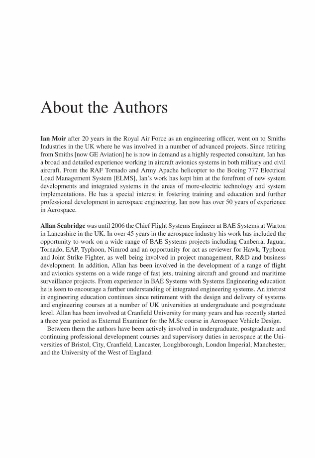
Ian Moir after 20 years in the Royal Air Force as an engineering officer, went on to SmithsIndustries in the UK where he was involved in a number of advanced projects. Since retiringfrom Smiths [now GE Aviation] he is now in demand as a highly respected consultant. Ian hasa broad and detailed experience working in aircraft avionics systems in both military and civilaircraft. From the RAF Tornado and Army Apache helicopter to the Boeing 777 ElectricalLoad Management System [ELMS], Ian’s work has kept him at the forefront of new systemdevelopments and integrated systems in the areas of more-electric technology and systemimplementations. He has a special interest in fostering training and education and furtherprofessional development in aerospace engineering. Ian now has over 50 years of experiencein Aerospace.
Allan Seabridge was until 2006 the Chief Flight Systems Engineer at BAE Systems at Wartonin Lancashire in the UK. In over 45 years in the aerospace industry his work has included theopportunity to work on a wide range of BAE Systems projects including Canberra, Jaguar,Tornado, EAP, Typhoon, Nimrod and an opportunity for act as reviewer for Hawk, Typhoonand Joint Strike Fighter, as well being involved in project management, R&D and businessdevelopment. In addition, Allan has been involved in the development of a range of flightand avionics systems on a wide range of fast jets, training aircraft and ground and maritimesurveillance projects. From experience in BAE Systems with Systems Engineering educationhe is keen to encourage a further understanding of integrated engineering systems. An interestin engineering education continues since retirement with the design and delivery of systemsand engineering courses at a number of UK universities at undergraduate and postgraduatelevel. Allan has been involved at Cranfield University for many years and has recently starteda three year period as External Examiner for the M.Sc course in Aerospace Vehicle Design.
Between them the authors have been actively involved in undergraduate, postgraduate andcontinuing professional development courses and supervisory duties in aerospace at the Uni-versities of Bristol, City, Cranfield, Lancaster, Loughborough, London Imperial, Manchester,and the University of the West of England.

Series Preface
Since the first publication of this book in 2004 there have been significant changes in theaerospace industry. Very large aircraft such as the A380 are in service and the Boeing 787 willintroduce radical new technological solutions to improve its ‘green’ credentials. Long range,transpolar operations are common place and there is growing pressure from the environmen-talist lobby to reduce emissions. Meanwhile passengers are faced with increasing fares andtaxes that could threaten the viability of the aviation industry.
The supply industry has changed, partly as a result of mergers and acquisitions and partlyfrom a desire of suppliers to acquire a greater share of the business available, altering thetraditional prime contractor/subcontractor relationships. Another factor driving amalgamationis increased competitiveness in both commercial and military sectors and the aspirations ofthe aerospace sectors in the emerging nations such as Brazil, India and China. The dominanceof domestic consumer markets has reduced the power of the aerospace industry to demandbespoke products in small volumes – a situation which is unlikely to be reversed. Emergingas a great challenge are unmanned air vehicles, used successfully in military theatres todaybut ultimately expected to appear in commercial applications. It is essential to move fromdevelopment of vehicles towards developing total systems – the vehicle and the supportingground systems – and their certification issues if unmanned air systems are to become asubiquitous as manned aircraft are today.
These factors place great emphasis on an understanding of the customer’s requirements andthe implementation of development process that provides a product with technical excellencewhilst meeting cost and schedule targets. This demands a measure of discipline in the designprocess to ensure that the requirements are analysed with competence, the design proceedsin an orderly and consistent fashion towards production and that the product is tested andcertificated as fit for purpose. Of major importance is that the product includes all aspects ofthe total system in which it is operated.
The aim of this book is to provide a familiarity with a generic process that can be tailoredto meet the needs of individual projects and to introduce project engineers to the complexinteractions that need to be understood and managed in contemporary projects. The intention,as with the first edition, is to provide a text that will be of use to practitioners but is also aimedat students and engineers wishing to enter the aerospace industry, whilst providing thoseprofessionals in allied disciplines an understanding of the process of developing a complexsystem.
Acknowledgements
There is no invention that does not possess a history, none that does not build on, or learn fromor owe a debt to the work of others.
Joseph Swan, 1828–1914.
From ‘Swan, 1924’ by Sean O’Brien, ‘Litmus: Short Stories from Modern Science’ Ed RaPage, Comma Press, 2011.
This work is the culmination of many years of work by both authors in the field of militaryand civil aircraft systems engineering. Our work experiences have been enriched by theopportunity to work with a number of universities at undergraduate and postgraduate levelto develop and add to degree courses, where the delegates unwittingly became critics andguinea pigs for our subject matter. Discussions during the courses with the academics and thestudents have broadened our knowledge considerably. In particular we would like to mentionthe Universities of Manchester, Loughborough, Cranfield, Bristol, University of the West ofEngland and Lancaster for their M.Sc and short courses attended by students and engineersfrom industry. At Cranfield special thanks must go to Dr Craig Lawson and Dr Huamin Jia forinviting us to participate in their MSc modules and short courses in Aircraft Systems Designand Avionics. Their students from the UK, Europe and China have been most attentive andhave made significant contributions to our knowledge. Dr Craig Lawson has also contributedan important section in Chapter 12 on the estimation of fuel penalties as part of the trade-offprocess.
Similarly at Bristol University and the University of the West of England where studentsfrom BAE Systems, Airbus, Rolls-Royce, Augusta Westland and European companies alsohave provided valuable inputs.
Cranfield University also gave us access to their group design project models, and ourappreciation to Barry White for his model making skills.
The reviewers are to be congratulated for their diligence and for their constructive commentsand criticism and our colleagues Malcolm Jukes, Roy Langton, Leon Skorczewski for theirunstinting advice and encouragement.
We have received considerable help from the staff at Wiley especially Debbie Cox, AnneHunt, Eric Willner and Liz Wingett as well as their proof readers, copy editors and publishingstaff.
Ian Moir and Allan SeabridgeApril 2012
Glossary
A4A Airlines for AmericaABS Automatic braking systemAC Alternating currentAC Airworthiness Circular – document offering advice on specific aircraft
operationsACMP AC driven motor pumpADC Air data computerADF Automatic direction findingADM Air data moduleADR Accident data recordingAFDX Avionics fast switched ethernetAHARS Attitude heading and reference systemAIMS Aircraft information management system (Boeing)Al AluminiumALU Arithmetic logic unitAMP Air motor driven pumpAPC Auxiliary power contactorAPU Auxiliary power unitARINC Air Radio INC (US)ARINC 400 Series of ARINC specifications providing a design foundation for avionicSeries equipmentARINC 404 Early ARINC standard relating to the packaging of avionic equipmentARINC 429 Widely used civil aviation data bus standardARINC 500 Series of ARINC specifications relating to the design of analogue avionicSeries equipmentARINC 578 ARINC standard relating to the design of VHF omni-range (VOR)ARINC 579 ARINC standard relating to the design of instrument landing systems (ILS)ARINC 600 Series of ARINC specifications relating to Enabling technologies forSeries avionic equipmentARINC 600 Later ARINC standard relating to the packaging of avionic equipmentARINC 629 ARINC standard relating to a 2Mbit/s digital data busARINC 700 Series of ARINC specifications relating to the design of digital avionicSeries equipmentARINC 708 ARINC standard relating to the design of weather radar
xviii Glossary
ARINC 755 ARINC standard relating to the design of multi-mode receivers (MMR)ARP Aerospace recommended practice (SAE)ASIC Application specific integrated circuitATA Air Transport AssociationATC Air Traffic ControlATI Air transport instrument – a means of specifying the size of aircraft
instrumentsAWG American wire gaugeBackwards The ability of systems to be compatible with earlier developments/
Compatibility configurationsBC Bus controller (MIL-STD-1553B data bus)BCAR British civil airworthiness requirementBIT Built-in testBMS Business management systemBPCU Bus power control unitBTB Bus tie breakerCAD Computer aided designCADMID UK MoD procurement processCAIV Cost as an independent variableCANbus Automotive data busCB Circuit breakerCDR Critical design reviewCFC Chloro-fluoro-carbon compoundsCG, cg Centre of gravityCNI Communications, navigation, identificationCold Soak Prolonged exposure to cold temperaturesCom Command channelCOTS Commercial-off-the-shelfCPIOM Common processor input/output moduleCPM Common processing moduleCPU Central processing unitCSG Computer symbol generatorCu CopperDC Direct currentDCMP DC motor driven pumpDef Stan Defence standardDME Distance measuring equipmentDMC Display management computerDoD Department of Defense (US)DOORS A requirements management toolDowney Cycle Procurement model used in the UK MoDDVI Direct voice inputEASA European Aviation Safety AdministrationECAM Electronic check-out and maintenance (Airbus)ECS Environmental control systemEDP Engine driven pump
Glossary xix
EDR Engineering design requirementsEEC Electronic engine controllerEFIS Electronic flight instrument systemEICAS Engine indication and crew alerting systemELMS Electrical load management systemEMC Electromagnetic compatibilityEMH Electromagnetic healthEMI Electromagnetic interferenceEPB External power breakerESM Electronic support measuresETOPS Extended Twin operationsEUROCAE European Organisation for Civil Aviation EquipmentFAA Federal Aviation Administration (US)FADEC Full authority digital engine controlFAV First article verificationFBW Fly-by-wireFCU Flight control unitFL Flight levelFMECA Failure mode and criticality analysisFMQGC Fuel management and quantity gauging computerFMS Flight management systemFOB Fuel on boardForwards The ability of systems to be compatible with future developments/
Compatibility configurationsFRR Final readiness reviewFull duplex A data bus that passes data in a bi-directional mannerG&C Guidance and controlGCB Generator control breakerGCU Generator control unitGHz 109 Hertz (gigaHertz)GPS Global positioning systemGPWS Ground proximity warning system- see also TAWSGUI Graphical user interfacegpm Gallons per minuteHalf duplex A data bus that passes data in a unidirectional mannerHALT Hardware accelerated life testHF High frequencyHIRF High intensity radio frequencyHMI Human machine interfaceHOTAS Hands on throttle and stickHot soak Prolonged exposure to high temperaturesHP Horse powerIAS Indicated airspeedIC Integrated circuitICD Interface control documentIDG Integrated drive generator
xx Glossary
IEEE 1498 High speed data busIFE In-flight entertainmentILS Instrument landing system – an approach aid used for guiding the aircraft on
a final approach to landingIMA Integrated modular architectureINCOSE International Council On Systems EngineeringINS Inertial navigation systemI/O Input/outputIPT Integrated product teamIR InfraredIRS Inertial reference systemISIS Integrated standby instrument systemIT Information technologyJAA Joint Aviation Authorities (Europe) See EASAkbits 103 bits (kilobits)LCD Liquid crystal displayLED Light emitting diodeLfE Learning from experienceLRI Line replaceable itemLRU Line replaceable unitLVDT Linear variable differential transformerMach The speed of an aircraft in relation to the speed of soundMAD Magnetic anomaly detectorMAU Modular avionics unitMBits 106 bits (megabits)MCDU Multifunction control and display unitMCU Modular concept unitMEA More electric aircraftMHz 106 Hertz (megaHertz)MIL-HBK Military Handbook – A US military publicationMIL-STD- Widely used military data bus standard1553BMLS Microwave landing system – an advanced approach aid used for guiding the
aircraft on a final approach to landingMMEL Master minimum equipment listMMR Multimode receiver – a receiver containing GPS, ILS and MLS receiversMoD Ministry of Defence (UK)Mode S A communication system used to exchange flight data between adjacent
aircraft and Air Traffic ControlMon Monitor channelMPCDU Multipurpose control and display unitMPP Master programme planNASA National Aeronautics & Space Administration (US)NATO North Atlantic Treaty OrganisationND Navigation displayNDA Non-disclosure agreement
Glossary xxi
NRC Non-recurring costsOAT Outside air temperatureOOD Object oriented designPBS Product breakdown structurePC Personal computerPDR Preliminary design reviewPFD Primary flight displayPHM Prognostics and health managementPMA Permanent magnet alternatorPoR Point of regulationPRR Production readiness reviewpsi Pounds per square inchPTU Power transfer unitQuadrax A four-wire full duplex data bus connection arrangement that enables data to
be passed each way thereby effectively achieving bi-directional data transfers(favoured by Airbus)
QMS Quality management systemRAM Random access memoryRASP Recognised air surface pictureRAT Ram air turbineR&D Research and developmentRF Radio frequencyRFI Request for informationRFP Request for proposalROM Read only memoryRT Remote terminal (MIL-STD-1553B data bus)RTCA Radio Technical Committee Association (US)RVDT Rotary variable differential transformerSAE Society of Automotive Engineers (US)SAHRS Secondary attitude and heading reference systemSARS Severe acute respiratory syndromeSATCOM Satellite communicationsSBAC Society of British Aerospace Companies (UK)SDD System design documentSDR System design reviewsfc Specific fuel consumptionSIGINT Signals intelligenceSOW Statement of workSPC Statistical process controlSRR System requirements reviewSSA System safety analysisSSPC Solid state power controllerSSR Software specification reviewStanag Standardisation agreement (NATO)SysML System modelling language
xxii Glossary
System ofSystems A system embracing a collection of other systems
TAS True airspeedTAWS Terrain avoidance warning systemTCAS Traffic collision avoidance systemTRR Test readiness reviewTRU Transformer rectifier unitTV TelevisionTwinax A two wire half duplex data bus connection that allows unidirectional data
transfers (favoured by Boeing)UAV Unmanned air vehicleUK United KingdomUML Unified modelling languageUS, USA United States (of America)USMS Utility systems management systemUTP Unshielded twisted pairUV UltravioletVHF Very high frequencyVMS Vehicle management systemVOR VHF omni-range; a commonly used navigation beacon in civil aerospaceVSCF Variable speed constant frequencyWBS Work breakdown structure
1Introduction
1.1 General
In three companion books in the Aerospace Series – Aircraft Systems [1], Civil AvionicSystems [2], and Military Avionics [3] the authors described the technical aspect of systemsfor military and commercial aircraft use – in essence the engineering of systems and systemproducts. Other books in the Series have also described the technical aspects of varioussystems, for example, fuel systems [4], and display systems [5]. However, we did not dwellon the mechanism by which such systems are designed and developed, and yet the processof systems development is a very important aspect that contributes to the consistency, qualityand robustness of design.
The first edition of this book tried to make amends and described the design and developmentprocess and the life cycle of typical aircraft systems. Since its initial publication the materialin the book has been used in a number of postgraduate courses and industrial short coursesfor aerospace systems engineers and has been developed to suit the engineering audience inresponse to questions received and discussions held during the course delivery.
This second edition is intended to be an introduction to aircraft systems and the systemsdevelopment process for students studying systems or aerospace subjects and wishing to enterthe aircraft industry or related industries, and for organisations sponsoring these people. Thecontent is intended to be of interest to people intending to join or already working in:
� Organisations directly involved in the design, development and manufacture of manned andunmanned, fixed-wing and rotary-wing aircraft – both military and commercial
� Systems and equipment supply companies involved in providing services, sub-systems,equipment and components to the manufacturers of aviation products
� Organisations involved in the repair, maintenance and overhaul of aircraft for their own useor on behalf of commercial or military operators
� Commercial airlines and armed forces operating their own or leased aircraft on a daily basis� Organisations involved in the training of personnel to work on aircraft
The book is also aimed at educational establishments involved in the teaching of systemsengineering, aerospace engineering or specialist branches of the topic such as avionics or
Design and Development of Aircraft Systems, Second Edition. Ian Moir and Allan Seabridge.© 2013 John Wiley & Sons, Ltd. Published 2013 by John Wiley & Sons, Ltd.
2 Design and Development of Aircraft Systems
Regulatory bodiesGovernment
THEAVIATION SYSTEM
Airline Operators
Users
General public
Aircraft Manufacturers
Suppliers
Caterers/Retail
Employees
Politicians
Pressure groupsTerrorists
Police/security
Trade unions
Transport operators
Airport Operators
Leisure industry
Military Operators
Commerce/Finance
Construction industry
Wildlife
Maintainers
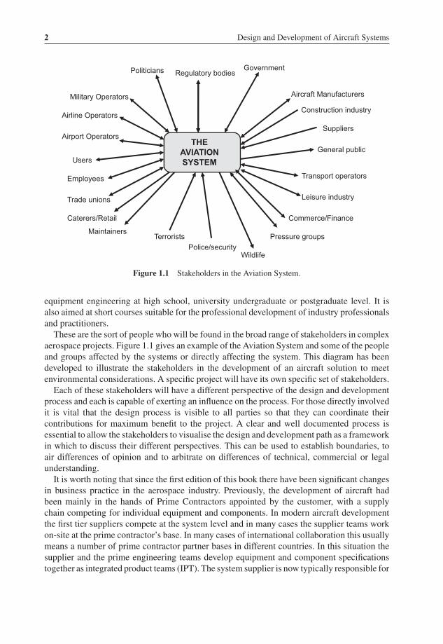
Figure 1.1 Stakeholders in the Aviation System.
equipment engineering at high school, university undergraduate or postgraduate level. It isalso aimed at short courses suitable for the professional development of industry professionalsand practitioners.
These are the sort of people who will be found in the broad range of stakeholders in complexaerospace projects. Figure 1.1 gives an example of the Aviation System and some of the peopleand groups affected by the systems or directly affecting the system. This diagram has beendeveloped to illustrate the stakeholders in the development of an aircraft solution to meetenvironmental considerations. A specific project will have its own specific set of stakeholders.
Each of these stakeholders will have a different perspective of the design and developmentprocess and each is capable of exerting an influence on the process. For those directly involvedit is vital that the design process is visible to all parties so that they can coordinate theircontributions for maximum benefit to the project. A clear and well documented process isessential to allow the stakeholders to visualise the design and development path as a frameworkin which to discuss their different perspectives. This can be used to establish boundaries, toair differences of opinion and to arbitrate on differences of technical, commercial or legalunderstanding.
It is worth noting that since the first edition of this book there have been significant changesin business practice in the aerospace industry. Previously, the development of aircraft hadbeen mainly in the hands of Prime Contractors appointed by the customer, with a supplychain competing for individual equipment and components. In modern aircraft developmentthe first tier suppliers compete at the system level and in many cases the supplier teams workon-site at the prime contractor’s base. In many cases of international collaboration this usuallymeans a number of prime contractor partner bases in different countries. In this situation thesupplier and the prime engineering teams develop equipment and component specificationstogether as integrated product teams (IPT). The system supplier is now typically responsible for
Introduction 3
system level and component level performance; and in many cases also responsible for directmaintenance costs associated with their system. This change in business practices demandsthat the supplier base becomes ‘systems smart’ and this book should provide a valuable insightfor the business community to fulfil this need effectively [6].
The principles established are equally applicable to other platforms, such as surface and sub-surface naval vessels, commercial marine vessels and land vehicles. The aerospace industryis almost unique, given the nature of an aircraft, in having to address high integrity andavailability, weight, volume, power consumption, cost and performance issues. The conflictof competing system drivers often makes trade-offs more acute when attempting to achievethe optimum balance of meeting the customer’s requirements and achieving an affordableproduct. There are also differences between commercial and military solutions that maydemand a subtly different interpretation of the process and the standards that apply. Theemergence of Unmanned Air Vehicles broadens the system concept to incorporate groundstations for remotely piloted vehicles. The striving for autonomous unmanned vehicles willlead to more innovative approaches to design and will require more rigour in the certificationof systems. Nevertheless, the process described in this book should be applicable, albeit withsuitable tailoring.
Although the text is formed around examples that are mainly aeronautical platform based thereader may also apply them to other high value systems such as ground-based radar, commu-nications, security systems, maritime and space vehicle based systems, or even manufacturingor industrial applications.
What makes all these platforms and systems similar is that they are all complex, high valueproducts comprised of many interacting sub-systems, and they are intended to be used bya human operator. They also share a common characteristic of having long operational lifecycles, often in excess of 25 years, usually with long gestation and development time-scales,the need for operator and maintenance training and full-life in-service support. Such time-scales demand a rigorous, controlled and consistent development process that can be used tomaintain an understanding of the standard or configuration of the platform throughout its life,in order to support repair, maintenance and update programmes.
1.2 Systems Development
There are many valuable lessons to be learned from the field of Systems Engineering. Theauthors believe that much of the theory and practice of Systems Engineering can be appliedto the engineering of hardware and software based systems for use in aircraft. It is a broadfield of practice that covers the behaviour of systems across wide range of subjects includingorganisational, operational, political, commercial, economic, human and educational systems.The concept of Systems and Systems Engineering operates at many different levels in manydifferent types of organisation. Much of the early analysis of systems behaviour was con-cerned with organisational or management issues – the so-called ‘soft’ systems. This workled to an understanding of the interactions of communications, people, processes and flows ofinformation within complex organisations [7, 8].
An important outcome from this work was the emergence of ‘systems thinking’. This termencompasses the ability to take a holistic or a total systems view of the development or analysisof any system. The key to this activity is the ability to take into account all influences or factors
4 Design and Development of Aircraft Systems
System
Sub-System Sub-System Sub-System
Sub-System Sub-System Sub-System
Sub-System Sub-System Sub-System
Sub-System Component
The total system – a system of systemsA major sub-system and its sub-systems
A lower level sub-system and its sub-systems
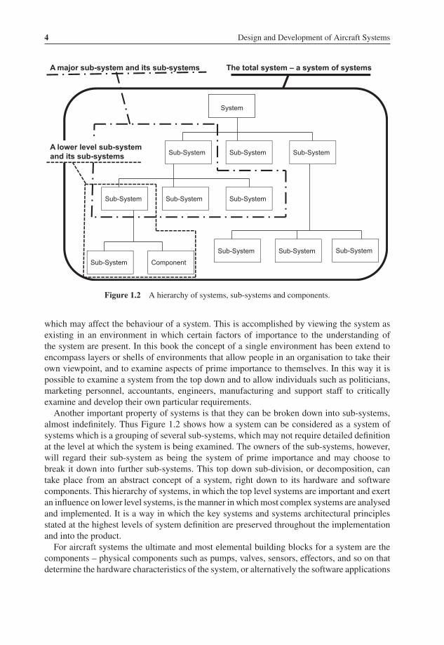
Figure 1.2 A hierarchy of systems, sub-systems and components.
which may affect the behaviour of a system. This is accomplished by viewing the system asexisting in an environment in which certain factors of importance to the understanding ofthe system are present. In this book the concept of a single environment has been extend toencompass layers or shells of environments that allow people in an organisation to take theirown viewpoint, and to examine aspects of prime importance to themselves. In this way it ispossible to examine a system from the top down and to allow individuals such as politicians,marketing personnel, accountants, engineers, manufacturing and support staff to criticallyexamine and develop their own particular requirements.
Another important property of systems is that they can be broken down into sub-systems,almost indefinitely. Thus Figure 1.2 shows how a system can be considered as a system ofsystems which is a grouping of several sub-systems, which may not require detailed definitionat the level at which the system is being examined. The owners of the sub-systems, however,will regard their sub-system as being the system of prime importance and may choose tobreak it down into further sub-systems. This top down sub-division, or decomposition, cantake place from an abstract concept of a system, right down to its hardware and softwarecomponents. This hierarchy of systems, in which the top level systems are important and exertan influence on lower level systems, is the manner in which most complex systems are analysedand implemented. It is a way in which the key systems and systems architectural principlesstated at the highest levels of system definition are preserved throughout the implementationand into the product.
For aircraft systems the ultimate and most elemental building blocks for a system are thecomponents – physical components such as pumps, valves, sensors, effectors, and so on thatdetermine the hardware characteristics of the system, or alternatively the software applications

Introduction 5
or modules that contribute to the overall system performance. The human, in the form of thepilot, crew member, passenger or maintainer is also a vital part of the system.
The decision on how far to keep decomposing a system into sub-systems depends on thecomplexity of the system and the ability to view the functions and interfaces as a whole. Atsome stage it may become necessary to construct a boundary around a system in order tospecify it to an external supplier for further analysis and design. An example of this is thedefinition of a sensor sub-system that will be more effectively developed and manufacturedby a specialist supplier.
Such a breakdown of systems into sub-systems, and yet further sub-systems and componentsreinforces another important aspect of systems and their interconnections. The outputs from asystem can form inputs to other systems. Indeed a system may produce an output, which is fedback to its own input as feedback. Feedback loops are not confined to one stage of a system,feedback may occur over several concatenated or interconnected systems in order to producesystem condition status or stability. Feedback may also be implemented using a data bus andmultiplexed processing units, which means that data latency must be taken into account. Toenable this to happen effectively in a hard system, the system interfaces must be defined toensure compatibility – that a system output is accepted and understood as an input so thatit can be acted upon. This requires that interfaces are well defined and rigorously controlledthroughout the development of the system.
It should also be noted that there have been significant changes in the aircraft supplierindustry resulting in mergers and acquisitions leading to large organisations with aspirationsto extend their business to tender for larger systems contracts. The mergers have increasedthe capability of suppliers to the extent that this is a feasible and sensible proposition. At thesame time some major prime contractors have focussed their sights on major system of systemmanagement contracts, concentrating their capabilities on management of design, design ofspecialist integration tasks, final assembly and qualification of the product.
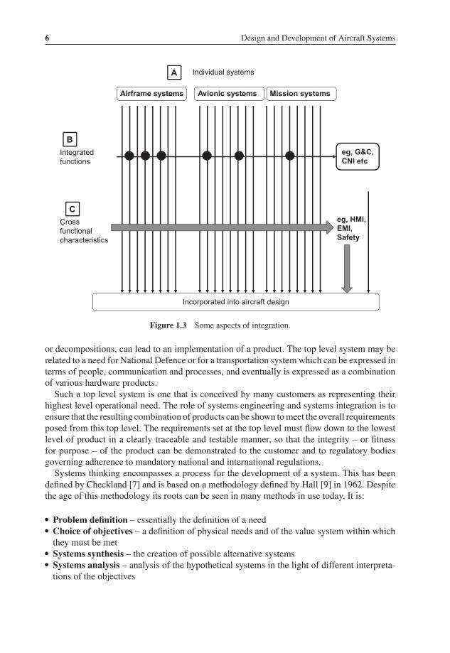
The ‘top down’ development of individual systems as practised in many line managementorganisations is shown in Figure 1.3 at point A.
This is the development path with which most engineers are familiar for all aircraft systems,avionics systems and mission systems treated as individual systems. However, there is oftena need for something more than this straightforward development route. Point B on the figureillustrates a case where certain systems are interconnected to form a synergistic integratedfunction – in other words a function is performed that is more than the sum of the individualsystem functions. An example of such a function is that of guidance and control (G&C)as an integration of functions of flight control, hydraulics, automatic flight control and fuelsystems, (See Chapter 6 for more detail). Also shown in this diagram is the integration ofcommunications, navigation and identification (CNI) systems.
Point C in the figure illustrates an alternative view of integration – that of a design aspectthat applies equally to all systems as a common discipline. Examples of this are safety, thehuman/machine interface (HMI), electromagnetic health (EMH) or maintainability. Thesedisciplines are governed centrally, usually by the Chief Engineer’s office, and their impact onthe individual systems will be gathered together to form a statement of design for the completeproduct.
The systems concepts described above can be used in aircraft systems engineering. Theycan be used to develop, from an understanding of a customer’s top level system requirements,a particular type of aircraft to perform a specific role and, after several successive analyses,
6 Design and Development of Aircraft Systems
Airframe systems Avionic systems Mission systems
Individual systems
Integratedfunctions
Crossfunctionalcharacteristics
Incorporated into aircraft design
A
B
C
eg, G&C,CNI etc
eg, HMI, EMI,Safety
Figure 1.3 Some aspects of integration.
or decompositions, can lead to an implementation of a product. The top level system may berelated to a need for National Defence or for a transportation system which can be expressed interms of people, communication and processes, and eventually is expressed as a combinationof various hardware products.
Such a top level system is one that is conceived by many customers as representing theirhighest level operational need. The role of systems engineering and systems integration is toensure that the resulting combination of products can be shown to meet the overall requirementsposed from this top level. The requirements set at the top level must flow down to the lowestlevel of product in a clearly traceable and testable manner, so that the integrity – or fitnessfor purpose – of the product can be demonstrated to the customer and to regulatory bodiesgoverning adherence to mandatory national and international regulations.
Systems thinking encompasses a process for the development of a system. This has beendefined by Checkland [7] and is based on a methodology defined by Hall [9] in 1962. Despitethe age of this methodology its roots can be seen in many methods in use today. It is:
� Problem definition – essentially the definition of a need� Choice of objectives – a definition of physical needs and of the value system within which
they must be met� Systems synthesis – the creation of possible alternative systems� Systems analysis – analysis of the hypothetical systems in the light of different interpreta-
tions of the objectives