design and analysis of a hierarchical ip traceback system
TRANSCRIPT
Design and Analysis of a Hierarchical IP Traceback System
by
Abes Dabir, B.A.Sc.
A thesis submitted to the
Faculty of Graduate Studies and Research
in partial fulfillment of the requirements for the degree of
Master of Applied Science in Electrical Engineering
Ottawa-Carleton Institute for Electrical and Computer Engineering
Department of Systems and Computer Engineering
Carleton University
Ottawa, Ontario
January 15, 2009
©Abes Dabir, 2009

1*1 Library and Archives Canada
Published Heritage Branch
395 Wellington Street Ottawa ON K1A0N4 Canada
Bibliotheque et Archives Canada
Direction du Patrimoine de I'edition
395, rue Wellington Ottawa ON K1A0N4 Canada
Your file Votre reference ISBN: 978-0-494-47509-6 Our file Notre reference ISBN: 978-0-494-47509-6
NOTICE: The author has granted a nonexclusive license allowing Library and Archives Canada to reproduce, publish, archive, preserve, conserve, communicate to the public by telecommunication or on the Internet, loan, distribute and sell theses worldwide, for commercial or noncommercial purposes, in microform, paper, electronic and/or any other formats.
AVIS: L'auteur a accorde une licence non exclusive permettant a la Bibliotheque et Archives Canada de reproduire, publier, archiver, sauvegarder, conserver, transmettre au public par telecommunication ou par Plntemet, prefer, distribuer et vendre des theses partout dans le monde, a des fins commerciales ou autres, sur support microforme, papier, electronique et/ou autres formats.
The author retains copyright ownership and moral rights in this thesis. Neither the thesis nor substantial extracts from it may be printed or otherwise reproduced without the author's permission.
L'auteur conserve la propriete du droit d'auteur et des droits moraux qui protege cette these. Ni la these ni des extraits substantiels de celle-ci ne doivent etre imprimes ou autrement reproduits sans son autorisation.
In compliance with the Canadian Privacy Act some supporting forms may have been removed from this thesis.
Conformement a la loi canadienne sur la protection de la vie privee, quelques formulaires secondaires ont ete enleves de cette these.
While these forms may be included in the document page count, their removal does not represent any loss of content from the thesis.
Canada
Bien que ces formulaires aient inclus dans la pagination, il n'y aura aucun contenu manquant.

The undersigned recommend to the Faculty of Graduate Studies
and Research acceptance of the thesis
Design and Analysis of a Hierarchical IP Traceback System
submitted by
Abes Dabir, B.A.Sc.
in partial fulfillment of the requirements for
the degree Master of Applied Science in Electrical Engineering
Chair, Department of Systems and Computer Engineering
Thesis Supervisor
Carleton University
January 15, 2009
u

Abstract
In this thesis, we present the detailed design and analysis of our solution to the IP
traceback problem. We adopt and enhance, at the Autonomous System (AS) level, a
path signature generation method which was proposed at the router level to primarily
provide a means of filtering attack traffic. Our solution assumes a secure BGP routing
infrastructure to exchange authenticated messages in order to learn path signatures.
This solution is hierarchical in the sense that it works at the AS-level first, then once
a small list of possible source ASes is identified, those ASes are queried and traceback
is performed within each AS to prune the list down to the actual source. We envision
the local adoption of a separate, yet complementary, traditional traceback system
at each AS. Using simulation results we demonstrate that our solution is practical
since it reduces - as a first step - the search space from the entire router space of the
Internet to an AS-list that is only a very small fraction of all possible ASes. We go on
to propose a means of using more than 16 bits of the IP fragmentation fields which
are traditionally used by various IP traceback systems. We present results based on
using various sizes for the marking field, as well as varying number of total marks
and different sizes for each mark.
hi

Acknowledgements
I would like express my deep gratitude and sincere thanks to my supervisor, Professor
Ashraf Matrawy, for his consistent guidance, support, and encouragement during the
course of my thesis. Thanks to him I learned the skills necessary to conduct research
in a professional manner.
I would also like to thank my family, especially my parents, Hassan and Farideh,
for their encouragement, support, and many sacrifices which have allowed me to reach
this stage in my life.
IV

To my parents: Hassan and Farideh
v

Contents
Acceptance Sheet ii
Abstract iii
Acknowledgements iv
Table of Contents vi
List of Tables xi
List of Figures xiii
List of Acronyms xv
1 Introduction 1
1.1 Motivation 1
1.2 Thesis Contributions 2
1.3 Thesis Outline 5
vi

2 Background on IP Traceback Technologies 7
2.1 IP Traceback Categories 8
2.1.1 Network Based IP Traceback 9
2.1.2 Packet Marking Based IP Traceback 10
2.1.3 Packet Logging Based IP Traceback 10
2.2 Probabilistic Packet Marking 10
2.2.1 Original PPM Approach 10
2.2.2 Advanced and Authenticated Marking Scheme 12
2.2.3 Fast Internet Traceback 12
2.2.4 iTrace 13
2.2.5 Intention Driven ICMP Traceback 14
2.3 Deterministic Packet Marking 15
2.3.1 Original DPM Approach 15
2.3.2 Stateless Single-Packet IP Traceback 16
2.3.3 AS-Level IP Traceback Using Bloom Filters 17
2.4 Packet Logging Based IP Traceback 18
2.4.1 SPIE 18
2.4.2 Layer 2 Extension to Hash-Based IP Traceback 19
2.4.3 AS-Level IP Traceback Using SPIE 20
2.5 IP Spoofing Mitigation Related Work 21
2.5.1 Ingress and Egress Filtering 21
vii

2.5.2 Unicast Reverse Path Forwarding 22
2.5.3 TCP Intercept 23
2.5.4 StackPi 23
2.5.5 Spoofing Prevention Method 23
2.5.6 Route-Based Distributed Packet Filtering 26
2.5.7 Defeating Distributed Denial-of-Service Attack with Determin
istic Bit Marking 27
2.6 IPv6 Considerations 30
2.7 Discussion on Presented Schemes 32
3 Design and Architecture of the Hierarchical IP Traceback System 34
3.1 Overview of Our Approach 34
3.2 Routing Infrastructure Considerations 35
3.2.1 Secure BGP Routing Environment 35
3.2.2 Using BGP to Transmit Capability Information 36
3.3 Finding Storage Space Inside of an IP Packet 39
3.4 Marking Packets - Simple Strategy 43
3.5 Marking Packets with Support for Incremental Deployment 44
3.6 Further Enhancements to Our Marking Strategy 45
3.7 Associating a Path Signature with its Source AS 47
3.7.1 Learning AS-Path Signatures 48
3.7.2 Single-Homed and Multi-Homed Customer Considerations . . 55
viii

3.8 Spoofing Detection and Other Security Considerations 58
3.9 Identifying the Origin AS (IP Traceback) 59
4 Simulation Models and Methodology 63
4.1 Topology Generation . 63
4.1.1 Average AS Path Length 66
4.2 NS-2 Modifications 68
4.2.1 Traffic Agents 69
4.2.2 Modifying Packets Enroute 69
4.3 Simulation Setup 70
4.3.1 Test Scenarios Executed 72
4.3.2 Simulation Phases 74
4.4 Analyzing Simulation Results 75
5 Results and Performance Analysis with Full Deployment 77
5.1 Traceback Using the Simple Marking Scheme 78
5.2 Effect of Number of Bits Per AS Mark and Number of Marks 79
5.3 Effect of Marking Strategy 80
6 Results and Performance Analysis with Partial Deployment 82
6.1 Marking Field Length 83
6.2 Effect of Topology 86
6.3 Varying the Number of Marks Recorded 88
ix

6.4 Effect of Marking Field on Learning Path Signatures 92
7 Conclusions and Future Work 94
7.1 Conclusions 94
7.2 Future Research 96
A NS-2 Modification Summary 97
Bibliography 100
x

List of Tables
5.1 Traceback results with full deployment (simple marking strategy, 16-
bit marking field, 4 marks) 79
5.2 Effect of increasing the size of each AS mark on the list of potential
source ASes (simple marking strategy, 4 marks in total) 80
5.3 Effect of increasing the size of each AS mark on the traceback success
rate (simple marking strategy, 4 marks in total) 80
5.4 Traceback results with full deployment (legacy-supporting marking
strategy, 16-bit marking field, 4 marks) 81
6.1 Traceback results with partial deployment (Inet3 topology with 5000
ASes, 16-bit vs 31-bit marking field, 4 marks) 84
6.2 Comparing traceback results between the Inet3 and Brite topologies
(31-bit marking field, 4 marks) 86
6.3 Traceback results with partial deployment (Brite topology with 5000
ASes, 4 to 6 marks) 88
XI

6.4 TVaceback results with partial deployment (Inet3 topology with 5000
ASes, 3 to 6 marks) 88
A.l List of all ns-2 files modified to implement our design 99
xn

List of Figures
2.1 Classification of IP traceback schemes 8
3.1 Structure of the BGP extended communities path attribute 38
3.2 IPv4 header 41
3.3 Basic marking scheme at the AS-level 44
3.4 Marking scheme with legacy AS support 45
3.5 On-demand request for path signature by AS 5 from origin AS 1 (as
suming simple marking strategy) 50
3.6 Path signature generation by a supporting AS on behalf of its neigh
bouring legacy ASes 54
3.7 Examples of customer network connectivity to ISP 56
3.8 Path signature matching methods for IP traceback 60
4.1 Histogram of mean distances in the Inet3 topology 65
4.2 Histogram of AS degrees in the Inet3 topology (only showing up to a
degree of 10) 65
xiii

4.3 Histogram of mean distances in the Brite topology 67
4.4 Histogram of AS degrees in the Brite topology (only showing up to a
degree of 10) 68
6.1 Comparison of traceback success rates using AMS and LMS methods
(Inet3 topology, 16-bit marking field, 4 marks) 84
6.2 Comparison of traceback success rates using AMS and LMS methods
(Inet3 topology, 31-bit marking field, 4 marks) 85
6.3 Comparing AMS traceback success rates between Inet3 and Brite topolo
gies (4 marks) 87
6.4 Comparing LMS traceback success rates between Inet3 and Brite topolo
gies (4 marks) 87
6.5 LMS traceback success rates comparison (Brite topology, 4 to 6 marks) 90
6.6 LMS traceback success rates comparison (Inet3 topology, 3 to 6 marks) 91
6.7 Comparison of traceback success rates using AMS and LMS methods
(Brite topology, 30-bit marking field, 5 marks) 92
xiv

List of Acronyms
AAM
ACL
AMS
AS
BGP
DBM
DF
DDoS
DoS
DPF
DPM
FIT
GBF
HMAC
IANA
Advanced and Authenticated Marking
Access Control List
All Matching Signatures
Autonomous System
Border Gateway Protocol
Distributed Bit Marking
Don't Fragment flag
Distributed Denial of Service
Denial of Service
Distributed Packet Filtering
Deterministic Packet Marking
Fast Internet Traceback
Generalized Bloom Filter
Hash Message Authentication Code
Internet Assigned Numbers Authority
XV

ICMP
IDS
IOS
IP
IRV
ISP
ITU
LMS
MAC
MD5
MF
NAT
nem
PKI
PPM
psBGP
RFC
S-BGP
so-BGP
SPIE
SPM
Internet Control Message Protocol
Intrusion Detection System
Internetwork Operating System
Internet Protocol
Interdomain Route Validation
Internet Service Provider
International Telecommunication Union
Longest Matching Signature
Media Access Control
Message-Digest algorithm 5
More Fragments flag
Network Address Translation
Network Manipulator
Public Key Infrastructure
Probabilistic Packet Marking
Pretty Secure Border Gateway Protocol
Request for Comments
Secure Border Gateway Protocol
Secure Origin Border Gateway Protocol
Source Path Isolation Engine
Spoofing Prevention Method
xvi

TCP Transmission Control Protocol
TTL Time To Live
ns-2 Network Simulator 2
UDP User Datagram Protocol
uRPF Unicast Reverse Path Forwarding
xvn

Chapter 1
Introduction
1.1 Motivation
As is evident from studies and news coverage over the past decade or so, there is
a considerable level of malicious/criminal activity (e-crimes) that take place over
the Internet, such as DoS, DDoS, worm and virus epidemics, extortion, espionage,
etc. The cost of such e-crimes can reach many millions, if not billions of dollars.
The number of such incidents is on the rise and this puts ever more pressure on
law enforcement and potential victims to counter or defend themselves against such
e-crimes.
Different categories of attack require different types of defenses and response mech
anisms. IP traceback, as defined by Savage et al. in [49], is a line of research that
tries to aid network operators when they are subjected to attack traffic whose IP
1
Introduction 2
source addresses are spoofed. IP traceback allows network operators to carry out
forensics on already received, or incoming traffic in order to identify the true source
of the traffic, as well as potentially identifying the network path the packet(s) has
taken. Typically the main avenues of attack that use spoofed source addresses are
DoS and DDoS attacks. DoS and DDoS attacks are a major area of concern for many
network operators. Surveys carried out by Arbor Networks in [36] indicate that from
August 2007 through July 2008, ISPs spent most of their available security resources
combating DDoS attacks.
While many solutions have been proposed over the years, they all suffer from cer
tain shortcomings and other issues that impact their feasibility. These shortcomings,
such as lack of legacy support, poor support for incremental deployment, high pro
cessing overhead or storage requirements, are discussed in more detail in Chapter 2
when we discuss a large number of currently proposed solutions. We believe there
is room for improvement in this area, and hence present our own solution to the IP
traceback and spoofing detection problems with the goal of concurrently addressing
many of these shortcomings.
1.2 Thesis Contributions
In this thesis we present our solution to the IP traceback problem. Our approach is
a hierarchical one that uses deterministic packet marking at the Autonomous System
(AS) level to identify the AS-path an incoming packet has taken. As well, we can

Introduction 3
narrow down the potential source ASes of the packet to a very small fraction of all
potential ASes. At the individual ASes we envision the local adoption of a separate IP
traceback system responsible for carrying out traceback within that AS, which would
work cooperatively with our approach to prune the list of potential source ASes of an
attack packet. Unlike many other approaches, ours supports incremental deployment.
Using simulation results we show that it performs well even in a partial deployment
scenario.
In StackPi [59] Perrig et al. proposed a method to create a unique router-path
signature for the path taken by a packet. They used this signature to filter out attack
packets having taken the same path and detect spoofed IP source addresses; they also
suggested it can be used for traceback. We explore the idea of creating a unique AS-
path signature by adopting, and building upon their technique. We believe doing this
at the AS level makes implementation much more practical. One significant advantage
of moving from the router level approach to the AS level is that AS-paths are highly
stable [20]. This means the path signatures we learn do not change nearly as often
as they would at the router level. Another advantage is that a packet traverses far
fewer ASes than individual routers, therefore each AS can use more bits to place its
mark in a packet than the number of bits each router could use for its mark. This
would in turn make for more distinct markings.
While StackPi primarily focused on providing a means of filtering DDoS attacks,
which also applies to our technique, we propose a more practical and detailed means

Introduction 4
of learning which path signatures belong to which sources in order to detect IP spoof
ing. We primarily explore the possibility of using such a technique to carry out IP
traceback on suspect packets. As well, we go on to suggest a method which would
allow using more bits from the 32-bit fragmentation fields for marking. We present
simulation results evaluating the impact of choosing variables such as the number of
bits used per AS mark and the total number of AS marks placed in each packet on
the accuracy of the results.
Overall, our contributions can be summarized as such:
• An AS-level path signature generation technique that benefits from BGP path
stability
• Proposed two detailed methods for learning AS-path signature in order to detect
packet spoofing and perform IP traceback
• Integrating research in the BGP routing security field with the StackPi proposal
to facilitate its functionality and better support incremental deployment
• Proposed a means to use more of the IP fragmentation bits for marking com
pared to existing proposals
• Proposed two techniques for AS-path signature comparison when performing
IP traceback
• Simulation-based evaluation of IP traceback using AS-path signatures
• Analysis of the impact of variables such as the number of bits allocated to each
mark, and the total number of recorded marks on the accuracy of the results

Introduction 5
The majority of solutions currently proposed do not offer this integrated solution
set, hence we believe ours to be a good candidate for future adoption, or serve as the
basis for future work in this area. We have submitted a conference paper [22] based
on the research presented in this thesis, which has been accepted in IEEE ICC 2009.
We have also produced a journal paper [23] which is under review.
1.3 Thesis Outline
The rest of this thesis is organized as follows:
In Chapter 2 we present some of the prominent related work in this area. These
works include both IP traceback and spoofing mitigation techniques. We go on to
discuss IPv6 considerations for this line of work.
In Chapter 3 we present the design details of our hierarchical IP traceback solution.
We discuss some of the requirements for our approach as it relates to the BGP routing
infrastructure. We explain what parts of the IP header we use to store traceback
marks, as well as how to use more portions of the IP header than what is commonly
used by various IP traceback approaches. We present our packet marking technique,
and propose two methods for tracing back the marked packets back to their source
AS.
In Chapter 4 we discuss how we generated our topologies, and the modifications
made to the tool used for running the simulations. We go into the details of the test
cases used, and the setup of each simulation.

Introduction 6
Chapter 5 contains the results of our testing where we have full deployment of our
solution by all ASes. In Chapter 6 we present similar simulation results for partial
deployment scenarios. In these chapters we present the effects of varying variables
such as the number of marks, the length of the marking field, changing the marking
strategy, changing the topology, etc.
Finally we present our concluding remarks in Chapter 7, along with possible di
rections for future research.

Chapter 2
Background on IP Traceback
Technologies
In this section we provide an overview of a number of approaches proposed in the area
of IP traceback over the years. We first identify the different categories of solutions,
and then discuss a few examples of prominent works in each category.
We will also discuss a number of works which are geared towards combating IP
spoofing only and do not provide an IP traceback mechanism. Since our approach
touches on both IP traceback as well as spoofing, it is important to discuss a number
of works in this field as well.
Several detailed survey papers have been published regarding the prominent IP
traceback approaches [14] [30] [27]. In this section we will put more emphasis towards
discussing approaches that are more relevant to our work.
7

Background on IP Traceback Technologies 8
The overwhelming majority of the work proposed thus far, and discussed here, is
based solely on IPv4. In the final part of this section we will discuss some of the IP
traceback proposals with IPv6 in mind. We will touch upon the differences between
the IPv4 and IPv6 protocols as they relate to the categories of traceback schemes
discussed.
2.1 IP Traceback Categories
Figure 2.1 shows the main categories of IP traceback schemes in squares, and the
most prominent proposal in each category is displayed in a circle. We will discuss
these in the following sections.
Packet Marking
In-band Out-of-band
( DPM j
IP Traceback Schemes
Packet Logging
SPIE
Network Based
Controlled; Flooding
Figure 2.1: Classification of IP traceback schemes

Background on IP Traceback Technologies 9
2.1.1 Network Based IP Traceback
Network based IP traceback mechanisms rely on the network structure itself, and
already available features in networking equipment to perform traceback. This cate
gory of IP traceback involves rather crude, manual approaches, and is not the subject
of new research in this field.
Controlled Flooding, presented in [19], is a classic network based traceback ap
proach. It relies on the assumption that the incoming links to the router closest to the
victim are heavily loaded. A large burst of traffic is applied to each of these incoming
router links in successive order. If after applying the traffic burst to an incoming
link of the router we observe a decrease in the rate of attack packets arriving at the
victim, then this means the link we are testing carries attack traffic. We would move
on to the upstream router the link we have identified is attached to and repeat the
same procedure to discover which of that router's incoming links is carrying attack
traffic. Applying this procedure recursively should eventually lead us to the network
edge router where attack traffic first enters the network. While potentially effective
against DoS attacks, this is a very manual and time consuming procedure. It will
not work against DDoS attacks which would involve multiple links of the same router
carrying attack traffic. On the plus side, this procedure requires no modifications to
the individual packets, or any storage in the network.

Background on IP Traceback Technologies 10
2.1.2 Packet Marking Based IP Traceback
All IP traceback schemes other than the network based variety rely on storing certain
information about each packet, or flow of packets, in order to carry out traceback.
Packet marking approaches generally incur a small amount of overhead at the routers
in exchange for large processing overhead at the final victim which has to use all the
marked information in order to reconstruct the attack path. In the in-band packet
marking schemes this information is stored in the header of each individual packet
before it is forwarded, while in the out-of-band marking schemes the information is
put into a separate new packet and sent to the victim.
2.1.3 Packet Logging Based IP Traceback
In contrast to the packet marking IP traceback schemes, logging based approaches
place the storage requirement on intermediate nodes along the path. In these ap
proaches, either the entire packet is logged, or more commonly, packet fingerprints
are stored in a specialized data structure and later used for traceback.
2.2 Probabilistic Packet Marking
2.2.1 Original P P M Approach
In [49] Savage et al. introduce the original Probabilistic Packet Marking (PPM)
scheme. In this scheme, at each router along the path of a packet, there is a probability

Background on IP Traceback Technologies 11
p that this router will mark the packet with partial information about the network
edge it is being forwarded on. This edge information consists of the IP address of
the current router, the IP address of the next router along the path, and a hop count
to the victim which will be incremented by every supporting router along the path.
The mark is placed in the 16-bit identification field of an IPv4 packet. While this
does break IP fragmentation, this choice is based on measurements suggesting that
less than 0.25% of IP traffic is fragmented. The very small size of this field compared
to the edge information that needs to be recorded in it limits how much information
can be stored when marking, hence only partial information can be accommodated
in the packet. Savage et al. propose a clever means to fragment a single piece of edge
information across multiple packets, and have these fragments reconstructed at the
victim. However, therein lies a lot of the weaknesses of their approach.
The victim is expected to collect all the marks it receives in incoming packets.
Due to the probabilistic nature of the marking, only a fraction of the packets will
contain a mark. Using the collected marks, the victim will execute a reconstruction
algorithm to reconstruct the path of the attack packets. Reconstruction is a very
time consuming process, requires a large number of packets (somewhere in the order
of several thousand), results in a large number of false positives, and does not work
well when the number of attack sources is high. Nevertheless, this work serves as a
foundation for much of the follow up work in the field of IP traceback.

Background on IP Traceback Technologies 12
2.2.2 Advanced and Authenticated Marking Scheme
This work was significantly improved by Song and Perrig in [51]. Their Advanced
and Authenticated Marking (AAM) scheme assumes the victim knows the map of its
upstream routers. Based on this assumption they can enhance the encoding principles
put forward by Savage et al. and make them efficient and accurate enough to scale
up to thousands of simultaneous attackers. This scheme requires a few thousand
packets as compared to the original PPM approach by Savage et al. which requires
several thousand packets to initiate traceback. As well, the computation time has
been reduced to about 100 seconds compared to the original approach which took
a few days to compute the attack route. Incremental deployment however is more
difficult with this approach than the original PPM approach [58].
2.2.3 Fast Internet Traceback
Fast Internet Traceback (FIT) [58] is yet another probabilistic packet marking scheme
that tries to improve on previous schemes in terms of deployability and performance.
Compared to the previous two PPM mechanisms mentioned, FIT requires tens of
packets to perform traceback, has better legacy support, and scales up to thousands
of attackers. It achieves these improvements over the previous PPM schemes by
manipulating the IP header's TTL field. It does overwrite the TTL field, however,
based on their analysis this doesn't cause major problems. Although, in some cases
packets with certain default TTLs, may persist in routing loops longer than they

Background on IP Traceback Technologies 13
would have without FIT in effect. Also, because of the requirement to overwrite the
TTL field, tools such as traceroute which are very sensitive to the TTL values and
use that as the basis for their functioning will not work. These would require new
implementations to work with FIT.
2.2.4 iTrace
One notable out-of-band packet IP traceback scheme is called iTrace [16]. Every
router statistically picks a packet it is forwarding (they recommend 1 in every 20,000),
and generates a new ICMP message destined to the same destination as the packet.
This ICMP message would contain as much of the traced packet as possible, a times-
tamp, authentication information, as well as information on the previous and next
hops. The victim would reconstruct the attack path based on the ICMP messages
received. The previous and next hop information in the iTrace packets received by
the victim would be pieced together across a chain of iTrace packets in order to iden
tify the attack route. The authentication options suggested, increasing in security
strength from left to right, are: cleartext random, strings, HMAC, digital signatures
backed by a PKI.
This scheme does not work against denial of service attacks that use very few
packets. It is best suited to a situation where a relatively small number of sources are
generating a significant amount of traffic. It remains a possibility that the one packet
chosen among 20,000 packets at a router to generate an iTrace packet based on, is

Background on IP Traceback Technologies 14
not actually an attack packet. Ideally iTrace packets should be generated based on
attack packets.
2.2.5 Intention Driven ICMP Traceback
In [39] Mankin et al. suggest a number of improvements over the iTrace method.
They focus on improving the usefulness of the iTrace packets generated. Their first
improvement involves sending iTrace packets only to destinations that the current
router knows support iTrace and are interested in receiving these packets. They
propose the use of the BGP protocol to distribute knowledge about which routers
want to receive iTrace packets.
In the original iTrace, once a packet statistically causes an iTrace packet to be
generated at a router, this iTrace packet would be sent to the triggering packet's
destination address. In this new scheme, the generated iTrace packet's destination is
decoupled from the destination IP of the triggering packet. A router maintains a list
of routing entries that want to receive iTrace packets. When a packet statistically
triggers the generation of an iTrace packet (the iTrace packet isn't generated right
away), the router randomly selects one of these routing entries to be the next to
receive an iTrace packet. The choice of which routing entry should get the next
iTrace packet has nothing to do with the contents of the packet that statistically
triggered this selection. The very next normal packet forwarded by this router to the
same network as the selected routing entry will cause a corresponding iTrace packet

Background on IP Traceback Technologies 15
to be generated and sent to this packet's destination IP address, with as much of this
packet copied into it as possible. This improvement causes more potential victims to
receive iTrace packets as opposed to a few victims receiving duplicate packets while
others receive none.
When selecting the next routing entry to receive an iTrace packet, this scheme
applies a level of bias towards destinations with longer AS paths. They argue that
there is relatively little value in generating iTrace packets for destinations that are 3
hops or less from the generating router.
2.3 Deterministic Packet Marking
2.3.1 Original DPM Approach
Deterministic Packet Marking (DPM) is another variation of this category where a
router marks every packet it forwards rather than only some packets with a given
probability. In [15], Belenky et al. proposed a DPM approach where only ingress
routers (border routers handling incoming traffic from outside the network) would
mark packets rather than all routers along the path. The mark would contain partial
identification information about the incoming interface on the ingress router. Every
time the packet enters a new network, its mark would be overwritten by that network's
ingress router. Using this system a victim would be able to use the collected marks to
deduce the address of the ingress router in the victim's own network where the attack

Background on IP Traceback Technologies 16
traffic is coming through. The researchers estimate this scheme requires roughly 55
marked packets for the victim to identify each ingress router interface attack traffic
is coming from. This would allow the victim to apply the proper filters at the entry
point of the attack traffic to its network. This approach does not aim to trace attack
traffic all the way back to the source network.
2.3.2 Stateless Single-Packet IP Traceback
In [37] Laufer et al. present an interesting deterministic packet marking approach
with the goal of being able to trace a single packet to its source. Their approach
involves embedding a new data structure, which is based on the well known Bloom
filter [17], into the IP header. They call this new data structure a Generalized Bloom
Filter (GBF). At every hop, the router places the hash of its IP address in the GBF
contained in the packet header. Path reconstruction is done incrementally at every
distance level, starting with the victim's direct neighbours. Whichever of the victim's
direct neighbours has the hash of its IP address present in the GBF will have to
check with its own neighbours to see which of them appear in the GBF. Recursively
following this process should lead to the source of the packet. The biggest hurdle to
this approach is the issue of where to place the GBF. The authors are not completely
clear on the size of the GBF, or their choice as to where to place it in the IP header.
However, we surmise that the GBF is far larger than the 16-bit IP identification field
and would have to accommodated as an IP option. This is not a feasible choice

Background on IP Traceback Technologies 17
however due to slow processing of IP options, especially since this would have to be
done at every hop.
2.3.3 AS-Level IP Traceback Using Bloom Filters
The above proposals all work at the router level. One of the in-band packet marking
proposals that works at the AS-level, which is where our own proposal works, is [21].
This proposal builds upon the work done by Laufer et al. in [37], which was discussed
in Section 2.3.2. It shares the same weakness as that proposal when it comes to
placing the relatively large GBF in the packet. In this approach each packet carries
GBF in its header, and every AS through which the packet passes places its mark in
it. At the destination AS, the victim can check which of its neighboring ASes have
their mark present in the bloom filter. Then the victim would check to see which of
the identified AS' neighboring ASes have their mark in the packet, and so on until
it reaches the source AS. In terms of impediments to implementation, similar to the
work this is based off, once again there is the problem of where to place the GBP in
the IP header. The main problem is still the fact that the GBF added to each packet
in order to store the marks is relatively large compared to the size of many small
packets frequently transmitted, as well as the fact that it would have to be added as
an IP option which significantly slows down router performance.

Background on IP Traceback Technologies 18
2.4 Packet Logging Based IF* Traceback
2.4.1 SPIE
The underlying packet logging technique that forms the basis for other related works
was carried out by Snoeren et al. in [50] and is called SPIE. The revolutionary idea
suggested by Snoeren et al. was to store fingerprints of each packet in a special data
structure called a Bloom filter on each router that the packet traverses. Storing packet
fingerprints in Bloom filters significantly cuts down on the storage requirements for
packet logging at the cost of more processing overhead and chance of false positives.
Their calculations suggested that the required amount of storage for a router link
would be around 0.5% of that link's capacity. Even at such levels, when dealing with
high speed links traffic can only be stored for a very short period of time.
The main disadvantages of this approach are the large amount of space required
for storing the Bloom filters, and the added processing for each packet which may
require specialized hardware. Legacy support is also an issue with SPIE. Consider an
example where we need to find out which of our 10 neighbouring routers forwarded
a packet. If 4 of these routers are legacy, then we would have to poll our 6 SPIE
supporting direct neighbours, as well as all the neighbouring routers of the 4 legacy
routers, which may themselves be legacy. This can result in having to contact a large
number of routers at each stage.
Some of the advantages of this approach include the ability to trace even a single

Background on IP Traceback Technologies 19
packet, moving the processing overhead from the victim to the routers, and leaving
the packets unmodified.
2.4.2 Layer 2 Extension to Hash-Based IP Traceback
In [32] Hazeyama et al. present an extension to hash-based IP traceback systems,
specifically the SPIE system already discussed, aimed at continuing the traceback
process at layer 2 to identify the specific node sending attack traffic. IP traceback
systems working at layer 3 are at best only capable of identifying the router closest
to the attacking node and not the individual node itself.
In this scheme, a leaf router would need to store and maintain a bloom filter to
hold layer 2 information, in addition to the existing Bloom filter from SPIE for layer
3 traceback. It would also require two conversion tables for MAC address to network
interface mappings on the leaf router, and MAC address to port identifier mappings
on the attached layer 2 switches. A leaf router would need to obtain the forwarding
databases of the switches attached to it so that it can map port identifiers to MAC
addresses on them. It can accomplish this if the switches in question are running
Bridge-MIB [24]. When a packet arrives at the leaf router, its signature is computed
as in SPIE and stored in the layer 3 bloom filter. The same computed signature is
concatenated with information identifying the originating switch port ID and subnet,
and is then stored in the layer 2 Bloom filter.
While this scheme adds layer 2 traceability, it increases the already high memory

Background on IP Traceback Technologies 20
and processing requirements of SPIE on a router implementing it. As well, the im
plementation of layer 2 traceback on a suspect packet is quite a bit more processor
intensive than layer 3 traceback with plain SPIE.
2.4.3 AS-Level IP Traceback Using SPIE
Another AS-level proposal which uses packet logging is introduced in [28]. In this
approach, we have a partial deployment scenario where a certain number of ASes
have SPIE deployed. In order to perform traceback on a packet, the victim AS asks
it neighbouring ASes to check their own packet logs and tell it which of them sent it
the packet. When one of its neighbours replies positively, it would then repeat the
same process with that AS' neighbours. If the reconstruction comes across a set of
ASes that don't have SPIE deployed and hence can't determine which of them sent it
the packet, the victim will have to use its knowledge of the AS topology and ask the
SPIE supporting neighbouring ASes of every legacy AS it is currently stuck at, hoping
one of them will respond positively. Amongst the disadvantages of this approach are
that its success rate drops quickly as the percentage of ASes deploying it goes down,
it generates a rather large number of query messages to perform traceback, and that
this has to be done for every single packet being traced.

Background on IP Traceback Technologies 21
2.5 IP Spoofing Mitigation Related Work
2.5.1 Ingress and Egress Filtering
Ingress and Egress filtering [34] are the two most common techniques currently used
to combat IP source address spoofing. Ingress filtering implemented at an ISP is done
from the customer edge site to the ISP. In this approach any customer traffic that
has a source address other than what has been assigned to the customer is dropped.
This does not prevent spoofed addresses within the customer IP prefix. In some cases
ingress filtering may break some services offered by an ISP such as Mobile IP [26].
Egress filtering implemented by an ISP is done from the ISP to the customer edge
site. Any traffic going to the customer with source addresses that are assigned to the
customer network are dropped.
Both these approaches are based on good-will and good net-citizenship by other
networks. They do not provide any assistance to a victim network under attack
from traffic passing through networks not implementing these features. As well, since
these two techniques are meant to help other networks, this limits the incentives for
individual networks to commit to the costs and administrative overhead of enabling
them when they may not receive any direct benefit themselves. The effectiveness
of ingress and egress filtering depends on large scale adoption by networks on the
Internet. Unless ingress filtering is carried out by almost all networks on the Internet,
it is not an effective DDoS prevention strategy [42].

Background on IP Traceback Technologies 22
If the victim network implements this type of filtering at its own edge, it can filter
out incoming attack packets that have source addresses belonging to its own network.
However, this is only a very small fraction of all possible spoofed source addresses. It
will not be able to filter out packets with spoofed source addresses belonging to other
networks.
2.5.2 Unicast Reverse Path Forwarding
Unicast Reverse Path Forwarding (Unicast RPF) [10] is a router feature for mitigating
malformed and spoofed IP packets. uRPF can be seen as an extension of ingress and
egress filtering strategies. When this feature is enabled on a router, upon receiving
a packet the router checks the source IP address and verifies that the source IP
network is reachable through the same interface (must be best return path) on which
the packet arrived. If this is not the case then the packet is dropped.
Among the limitations of uRPF are that it is best implemented in the presence
of symmetric paths. Asymmetric paths require ACLs to prevent packets from being
dropped and complicate its implementation. Furthermore, simply ensuring that the
incoming interface is the best return path to the packet's claimed source network does
not guarantee that the source IP is not spoofed.

Background on IP Traceback Technologies 23
2.5.3 T C P Intercept
TCP Intercept [9] is a feature available in the Cisco IOS software. This feature is
meant to protect servers running TCP services from TCP SYN-Flood type DDoS
attacks. It does this by intercepting and validating TCP connection requests. If a
TCP connection can be fully established, it indicates that the source IP address is
not spoofed. Two limitations of this approach are that it puts a heavy burden on the
router that has it enabled, and that it only works for TCP type traffic.
2.5.4 StackPi
Another relevant security proposal we would like to discuss is StackPi [59]. This work
is primarily intended to create a unique path signature for the router-path taken by a
packet, and use this signature to filter out attack packets having taken the same path.
It does this by deterministically marking the IP identification field of a packet at every
router that forwards it. Each router shifts the current bits in the IP identification
field left by n bits before putting its own n-bit mark at the rightmost end of this
field. While this work leaves the door open to IP traceback, it does not explore this
field itself and focuses on filtering.
2.5.5 Spoofing Prevention Method
The Spoofing Prevention Method (SPM) [18] is solely an anti-spoofing method, mean
ing it does not support traceback. In SPM, each source and destination AS pair are

Background on IP Traceback Technologies 24
required to share a key, which is chosen and placed in the packet (they call it tagging)
by the source AS and is verified at destination AS. This key is a simple string of 32,
or 16 bits. Verifying the key at the destination AS simply involves checking to see if
the packet contains the same key as what is expected of the AS it is claiming to have
originated from. There is no cryptography involved in this verification process.
The researchers suggest placing this key in the packet header as either a 32-bit
value in the IP options field, or as a 16-bit value in the IP fragmentation ID field.
Placing the key in the IP options field is not feasible due to the significant overhead it
would introduce, therefore the latter approach is the only feasible choice. This would
limit the key length to 16 bits.
In SPM only the source AS tags packets originating from it. It is recommended
that the intermediate ASes along the way authenticate the tagged key in packets they
forward so as to drop spoofed packets as early as possible in the forwarding process.
This however means that an intermediate AS would need extensive knowledge about
the keys used between each source and destination AS, which could number in the
billions and require gigabytes to store, depending on how many ASes adopt SPM. It
should also be noted that given a 16-bit key length, and requiring a key for every
source and destination AS pair results in a significant number of such pairs sharing
the same keys.
Each AS independently chooses the set of keys it will use to mark traffic originating
from it. These keys are then communicated with other ASes having implemented

Background on IP Traceback Technologies 25
SPM. They propose two methods for key distribution. In the first method an AS
learns which keys to expect from source ASes by monitoring non-spoofed incoming
traffic. Incoming traffic is judged to be non-spoofed if it completes the three-way
TCP handshake. The second key distribution mechanism uses an active distribution
protocol which borrows from architectures proposed by researchers to secure the BGP
routing infrastructure. Specifically they base their protocol on the IRV [29] BGP
security architecture in which each participating AS has a dedicated central server
used to ensure the integrity of BGP information. We discuss the IRV architecture in
more detail in Sec. 3.2.1. In SPM such a central server is used to announce keys to
other ASes, and receive key announcements from other ASes.
The researchers do not discuss legacy support in detail. Since tagging packets with
a key is only done at the source AS, SPM will not have any support for legacy source
ASes. It is not possible for intermediate ASes to tag packets having been originated
in a legacy AS, because the destination AS looks specifically for a tag corresponding
to the source IP address' AS and itself, not some intermediate AS. The address of an
intermediate AS which might compensate for a legacy AS by tagging the packet for
the first time would not be in the packet itself, therefore the destination AS will not
be able to verify the key.
As previously mentioned, this technique does not support IP traceback, therefore
a victim AS will not be able to locate, or narrow down the potential sources of spoofed
traffic.

Background on IP Traceback Technologies 26
2.5.6 Route-Based Distributed Packet Filtering
Route-based distributed packet filtering (DPF) [42] is a novel approach presented
to combat both spoofing and allow for IP traceback at the AS level. DPF achieves
these goals by using very detailed BGP AS topology and routing information to
determine if an incoming packet is valid with respect to its source and destination
addresses, given the reachability constraints imposed on it by the aforementioned
pieces of information. The approach presented is able to achieve relatively accurate
results in the presence of a large number of legacy ASes. This approach, similar to
ingress filtering, has issues regarding incentive for individual ASes to implement it.
However, unlike ingress filtering DPF can deliver much better results given roughly
20% deployment.
Using the same detailed BGP AS topology and routing information constraints,
DPF can carry out IP traceback at the AS level on spoofed traffic. When comparing
their results with ours under similar circumstances, our approach presented in this
thesis can deliver traceback results which are quite a bit more accurate. We refer
to similar circumstances here because a lot of the results presented in [42] are based
on making assumptions that would work in their favor. An example of one such
assumption would be that there is only one (shortest path), or very few possible
routes from a source AS to a destination AS being used out of all possible non-looped
routes.
The main issue with DPF however is gathering the very detailed topology and

Background on IP Traceback Technologies 27
routing constraint information it needs in order to operate. DPF requires source
reachability information to function as opposed to just destination reachability infor
mation which is what is carried in BGP messages. DPF would require a new protocol
to carry such information. As noted by the authors they do not have an answer to
the efficient implement ability of their solution for IP internets. Nevertheless, DPF
presents a number of interesting ideas which can benefit our own solution to narrow
down the space of possible source ASes we identify. Similarly, DPF can benefit from
our approach as well.
2.5.7 Defeating Distributed Denial-of-Service Attack with De
terministic Bit Marking
In [35] Kim et al. propose a router-level deterministic marking strategy that shares a
number of similarities with the already discussed StackPi approach. Their approach,
which is called deterministic bit marking (DBM), is not meant to detect spoofing,
rather it is meant to serve as a means of isolating and discarding DDoS traffic based
on the common path signature in these packets. DBM also allows the possibility of
IP traceback.
Like StackPi, DBM is also centered around the idea of creating a unique path
signature at the router-level for the path a packet travels. Their marking strategy is
very different than StackPi's however, and we believe it is inferior as will be explained
shortly. Like many other approaches they propose to use the 16-bit IP identification
Background on IP Traceback Technologies 28
field for this mark, although they also present a more advanced version of their
approach where they also make use of an additional 13 bits in the IP Fragment
offset field.
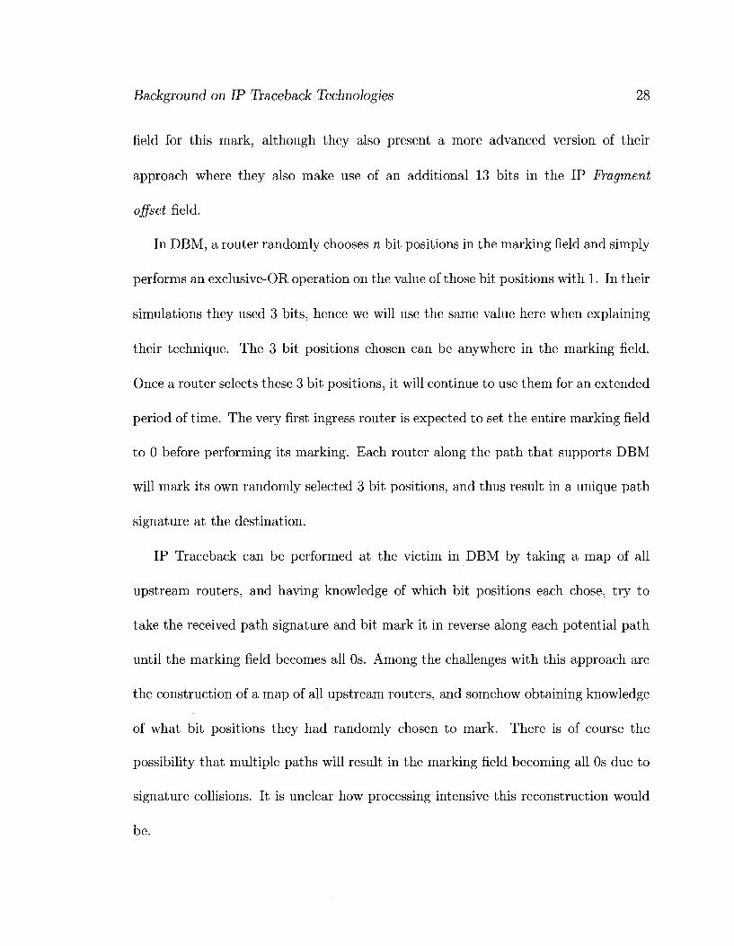
In DBM, a router randomly chooses n bit positions in the marking field and simply
performs an exclusive-OR operation on the value of those bit positions with 1. In their
simulations they used 3 bits, hence we will use the same value here when explaining
their technique. The 3 bit positions chosen can be anywhere in the marking field.
Once a router selects these 3 bit positions, it will continue to use them for an extended
period of time. The very first ingress router is expected to set the entire marking field
to 0 before performing its marking. Each router along the path that supports DBM
will mark its own randomly selected 3 bit positions, and thus result in a unique path
signature at the destination.
IP Traceback can be performed at the victim in DBM by taking a map of all
upstream routers, and having knowledge of which bit positions each chose, try to
take the received path signature and bit mark it in reverse along each potential path
until the marking field becomes all Os. Among the challenges with this approach are
the construction of a map of all upstream routers, and somehow obtaining knowledge
of what bit positions they had randomly chosen to mark. There is of course the
possibility that multiple paths will result in the marking field becoming all Os due to
signature collisions. It is unclear how processing intensive this reconstruction would
be.

Background on IP Traceback Technologies 29
Both StackPi and DBM share the problem of working at the router-level where
routing paths are not all that stable and may change often. DBM's reliance on the
very first router to set the marking field to all Os is a major problem which sets
it apart from StackPi. DBM's functionality would be significantly reduced in the
presence of legacy routers, while StackPi would be much more functional in the same
situation. If the very first ingress router in the DBM approach does not set the
IP identification field to all Os, then there is a good chance some of the randomly
initiated values in that field will not be touched by the DBM supporting routers and
make it to the final destination. This would cause the path signature in each packet
to be completely different. Since the bit positions in DBM can be chosen anywhere
in the marking field, it would be very difficult to separate the random bits from the
legitimate marking bits. In StackPi since the random initialized bits are constants
shifted out of the packet to one side as new marks are placed, it is much easier to
deduce the random bits from the legitimate marking bits.
The authors also present a more advanced version of their approach that uses a
29-bit marking field. The extra 13 bits are used for a checksum on the value of the
first 16 bits of the marking field plus the value of the TTL field at the time the mark
was placed in the packet. The first 16 bits are marked as before. The purpose of this
is that if at a DBM supporting router, the DBM checksum in an incoming packet
matches the mark, then the packet must have been forwarded from a DBM supporting
router which marked it. Otherwise, the packet is considered to be unmarked. The

Background on IP Traceback Technologies 30
problem here is that if there is a single legacy router along the path, as soon as
this legacy router decrements the TTL it will invalidate the checksum and the entire
packet will be considered unmarked by all subsequent DBM supporting routers.
2.6 IPv6 Considerations
While there are clearly differences between IPv4 [43] and IPv6 [25], as far as IP
traceback is concerned, much of the same ideas that were applied in the realm of
IPv4 also apply in IPv6. There are some modifications that need to be made to these
solutions of course.
In [53] Strayer et al. present an IPv6 compatible version of SPIE, the prominent
packet logging solution based on Bloom filters. The main difference with the IPv4
version lies in which parts of a packet are used in computing a hash signature to store
in the Bloom filter. One interesting observation they make is that the IPv6 packet
header does not exhibit as much entropy as the IPv4 header. One reason for this is
that the IPv4 identification field, which is set to a random value before transmission
by the sending node, is no longer present in the IPv6 header. Consequently in an
IPv6 environment SPIE would have to use quite a bit more data from the packet as
input into its hash calculation function.
The packet marking approaches are perhaps more affected by moving to IPv6 as
opposed to logging-based approaches. Most packet marking approaches in IPv6 at
tempt to find a header field comparable to the IPv4 identification field. The original

Background on IP Traceback Technologies 31
probabilistic packet marking approach proposed by Savage et al. for IPv4 mentions
the 20-bit IPv6 Flow Label field as a viable option to replace the IPv4 identification
field when it comes to marking. In [12] for example, the researchers attempt to im
plement the advanced packet marking approach, which was discussed earlier, in IPv6.
IPv6 packet marking approaches that do not use this field, such as [13], instead use
the hop-by-hop IPv6 extension header to store the packet mark, which is equivalent
to IPv4 options. This is not feasible for the same reasons IPv4 options were not
feasible, which is due to the fact that they have to be handled in software [8] and
significantly slow down packet processing.
The IPv6 Flow Label field, the specifications of which are extensively discussed
in [44], may be used by a source to request special handling by IPv6 routers for a
sequence of packets it has labeled. At the IPv6 level, a flow is identified by a 3-
tuple consisting of a flow label, as well as source and destination addresses. This
field however is still experimental and subject to change as the requirements for flow
support in the Internet become more clear. If a packet's Flow Label field is used for IP
traceback, its contents would only undergo unwanted modification if it passes through
a legacy IPv6 router, with flow specific treatment enabled, if the packet's flow label
matches an existing one on that router with the same source and destination address
pair. It is not clear how probable this might be. Otherwise, using this field for IP
traceback in IPv6 should be fine.
While the IPv6 Flow Label field does grant an additional 4 bits compared to the

Background on IP Traceback Technologies 32
16-bit IPv4 identification field, we should keep in mind that IPv6 addresses are 128
bits long as opposed to 32-bit IPv4 addresses. This makes the job of packet marking
approaches more difficult when fragmenting edge, or similar, information and placing
them across multiple fragments for later reassembly. This causes more false positives,
more packets required for IP traceback, and lesser accuracy compared to IPv4.
2.7 Discussion on Presented Schemes
In this Chapter we have presented, and evaluated, various IP traceback and spoofing
detection schemes. Within this context, we will now briefly discuss the advantages of
our solution, which we present in Chapter 3, in order to distinguish it from the rest.
The probabilistic packet marking set of IP traceback solutions we discussed are
primarily concerned with reconstructing attack paths based on information gathered
from a large number of attack packets. If we select an individual attack packet, these
approaches cannot identify which path it came from since an individual packet does
not contain enough information to reveal this. Nor can they tell us if an incoming
packet is spoofed or not.
In our solution, we aim to allow for per-packet IP traceback. Each packet will
contain enough marking information so that we can narrow down its possible source
to a small set of ASes. Per-packet IP traceback capability is a highly desired feature
in this area. As well, the mapping from marking information to the set of potential
source ASes can be done almost instantaneously, which allows for a fast response time.

Background on IP Traceback Technologies 33
PPM-like approaches on the other hand can require a very long time to construct the
possible attack paths. The original DPM approach is intended to identify the ingress
router of the victim network only, not the actual source. Approaches such as SPIE,
which can trace individual messages, require considerable communication between
upstream routers to trace each packet.
IP traceback solutions in general do not provide any means to quickly determine
if a packet arriving at the victim (or victim network) is spoofed or not. Alternatively,
solutions aimed at identifying incoming spoofed packets do not necessarily allow for
IP traceback. In our solution we provide both functions.
Scalability and legacy support are of course two important requirements for an
effective solution in this area, and we have designed ours to meet these requirements.
Scalability is applicable both in terms of deployment, and the ability to trace a large
number of attackers under a wide-spread DDoS attack for example.
Our solution of course requires a number of trade-offs to achieve these qualities,
however we believe all of these to be realistic and feasible. Our requirements in the
areas of additional network bandwidth, processing and storage overhead at routers,
and management overhead are all low to moderate when compared to the other works
proposed.
Chapter 3
Design and Architecture of the
Hierarchical IP Traceback System
3.1 Overview of Our Approach
The underlying idea behind the marking strategy in our solution is that as a packet
traverses ASes, each AS adds its own mark to the packet's header. By the time the
packet reaches its destination AS, the marks placed in its header form a signature
unique (as much as possible) to the AS-path it has taken. These path signatures can
be used to perform IP traceback by comparing the path signature of an incoming
packet with previously acquired path signatures whose origin ASes are known1. In
this paper we propose and evaluate two methods for comparing signatures when
xPath signatures can also be used to filter out attack packets originating from the same source and to identify a packet as spoofed if the path signature it contains does not match the one expected of the source it is claiming to be coming from.
34

Design and Architecture of the Hierarchical IP Traceback System 35
performing IP traceback.
3.2 Routing Infrastructure Considerations
3.2.1 Secure B G P Routing Environment
The Border Gateway Protocol (BGP) [46] is the standard inter-AS routing protocol
used between ASes to discover and maintain routing information in order to guide
traffic across the Internet. The current routing infrastructure is vulnerable to a num
ber of malicious attacks due to a lack of a secure means to verify the authenticity
and integrity of BGP control messages. For many years now researchers have been
coming up with proposals to address the security issues in the BGP routing infras
tructure. Some of the notable approaches proposed include S-BGP [33], so-BGP [56],
and psBGP [54]. For an informative summary of these three proposed systems, the
reader is referred to [55].
Another approach to secure BGP, which we would like to briefly discuss here
also, is called Interdomain Route Validation (IRV) [29]. Compared to the other three
approaches mentioned earlier, IRV is more geared towards incremental deployment.
It is a new protocol separate from BGP, which serves as a companion to it. IRV
is receiver-driven in the sense that it enables the receiver of BGP information to
communicate with the sender and corroborate the information. Each AS has an IRV
server, which can communicate directly with the IRV server of another AS over a

Design and Architecture of the Hierarchical IP Traceback System 36
secure channel to corroborate information it may have sent. Similarly, in our approach
each AS has a dedicated server for our solution, which can communicate directly with
the dedicated servers of other ASes.
Our approach requires that a secure inter-AS (BGP) routing infrastructure be
present so that ASes deploying our solution can reliably learn which IP prefixes are
assigned to which ASes. This infrastructure would also be used to exchange authenti
cated messages in order to associate path signatures of packets with their true source
ASes. We assume the eventual adoption of a secured BGP routing infrastructure to
combat other serious security issues on the Internet, and to facilitate a multitude
of security services in IP network. Based on this we believe our assumption to be
reasonable. For our purposes we can assume that whichever method is eventually
implemented, it provides each AS with a public key certificate whose corresponding
private key can be used to sign outgoing messages.
3.2.2 Using BGP to Transmit Capability Information
BGP speaking routers regularly exchange routing information using BGP update mes
sages. These update messages may contain a number of path attributes. The optional
extended communities path attribute [48] can be used to pass additional information
to both neighbouring and remote BGP peers, and thus create a logical grouping of
ASes that share common characteristics.
We propose the use of the transitive BGP extended communities path attribute

Design and Architecture of the Hierarchical IP Traceback System 37
in order for ASes to learn which other ASes also support our solution in a partial
deployment scenario with legacy ASes present. This should aid the incremental de
ployment of our solution in an environment where not all ASes will initially support
it. The extended communities path attribute would be distributed as part of outgo
ing BGP update messages being sent out by ASes that support our solution. The
transmitted BGP updates with this new path attribute would lead to the creation
of a logical community within the network of interconnected ASes that support our
solution. Legacy ASes are not a problem in this approach because they are expected
to pass along an unrecognized transitive path attribute without any modification.
3.2.2.1 Encoding Format for the Extended Communities Path Attribute
A BGP extended communities attribute, as illustrated in Fig. 3.1, is 8 bytes long,
and consists of a type and value fields. The type field can be either one or two bytes
long, while the value field would occupy the remaining bytes. The most significant 4
bits of the first byte in the type field constitute flags. We would need a new unique
BGP extended community type to be allocated by IANA [2] for use by our solution.
An AS supporting our solution that is sending out a BGP update with an extended
communities path attribute in it, would set the type field of the path attribute to
the IANA [2] assigned value for our solution, and would set the value field to the IP
address of a server within this AS that is responsible for running tasks specifically
related to our solution. The responsibilities of this server will be further discussed in

Design and Architecture of the Hierarchical IP Traceback System 38
section 3.7.
| Byte 0 | Byte 1 | Byte 2 | Byte 4 |
Type high* Type low
Value
* Most significant 4 bits are flags
Figure 3.1: Structure of the BGP extended communities path attribute
There is a complication with the approach described here to transmit capability
information. A BGP path attribute can be variable length and occupy many bytes.
However, the structure of the extended communities path attribute has been specifi
cally defined to be constant in length and limited to only 8 bytes. Eight bytes is long
enough to accommodate a 4-byte long IPv4 address in the value field, however it is
not long enough to accommodate a 16-byte long IPv6 address. Since the extended
communities path attribute is in principle designed to achieve the same type of ob
jectives we are after here, it is unwise to abandon it and require an entirely new kind
of BGP path attribute be defined for our solution.
It should be possible to work around the 8-byte length limitation in the extended
communities path attribute. A BGP update message can contain a variable number
of path attributes. Therefore, we simply propose using two extended communities
path attributes in a single update message to convey the IPv6 address of the sending
AS' server responsible for performing functionality specific to our solution. Overall,
Design and Architecture of the Hierarchical IP Traceback System 39
we would need four extended community types assigned by IANA as follows:
1. Used in an IPv4 environment
2. Used in an IPv6 environment; contains the first part of the server's IPv6 address
3. Used in an IPv6 environment; contains the second part of the server's IPv6
address
4. Used in an IPv6 environment; contains the third part of the server's IPv6 ad
dress
It is also possible to get by with just three extended community type values by
making use of the Partial bit flag. As previously mentioned, the most significant 4
bits of the first byte in the type field are flags. The third high order bit of these flags is
the Partial bit flag, which defines whether the information in the optional transitive
path attribute is partial or complete. Our first IANA assigned extended community
type can be interpreted to be paired with an IPv4 address if the partial bit is set to
0, and be interpreted to be paired with the first part of an IPv6 address if set to 1.
3.3 Finding Storage Space Inside of an IP Packet
Each AS along the path needs to insert a small amount of information in the packet's
header. IP was not designed with such a requirement in mind, at least not for real
time forwarding of a large number of packets. Using IP options for this purpose
is not feasible because it significantly slows down processing speed and can lead to

Design and Architecture of the Hierarchical IP Traceback System 40
fragmentation or dropped packets as a result of increasing the packet's size. Savage
et al. addressed this problem in [49] by overloading the rarely used 16-bit IPv4
identification field normally used for fragmentation. It should be noted that this
field is initialized to some random value before transmission by the sending node's
operating system.
Since we are already breaking fragmentation by overloading the IP identification
field as is done in many IP traceback approaches, we looked into the possibility of
using the remaining fragmentation bits in the IP header while minimizing any negative
impacts this would have. Most approaches do not use the remaining fragmentation
bits, and those that do, do not address the adverse effects it would have. Fig. 3.2
illustrates the format of the IPv4 header, and should help the reader better visualize
what we are about to discuss. The three flags in Fig. 3.2 are as follows:
• R: Reserved
• DF: Do not fragment
• MF: More fragments
Current approaches do not use the remaining bits because it may cause some net
working stacks, such as the Linux 2.6 [11] network stack, to mistake marked packets
for fragmented ones. We examined the source code for kernel version 2.6.26 specif
ically, to see how it determines if an IP packet is a fragment or not. This checking
is done in ipJnput.c, in function ipJocaLdeliver(...). A packet is considered to be a
fragment:

Design and Architecture of the Hierarchical IP Traceback System 41
ByteO
Version IHL
By te l
TOS
Identification
TTL Protocol
Byte 2 I Byte 3 |
Total Length
R D F
M F Fragment Offset
Header Checksum
Source IP Address
Destination IP Address
IP Options + Padding...
Figure 3.2: IPv4 header
1. If this is the last fragment (MF=0 AND Fragment Offset is non-zero)
2. If more fragments follow this fragment (MF=1)
What we observed was that the code was not checking the value of the Do not
fragment (DF) flag. Logically if the DF flag is set, the packet should not be treated
as a fragment, no matter what the values of the MF flag and the fragment offset field
are. Of course in normal IPv4 operation there should be no situation in which DF is
set while the other two variables indicate a packet fragment.
We believe we can use the Reserved flag, which is currently unused, as part of the
marking field in our marking scheme without any issues. Should it ever be needed in
the future as part of a specific feature, this one bit will not significantly impact our
results.
We can use the DF flag to propose a very minor change to the stack code where
a packet is not treated as a fragment if this flag is set. Checking this additional flag

Design and Architecture of the Hierarchical IP Traceback System 42
when deciding if a packet is a fragment or not is trivial. This should let us use as
much as 31 bits of the fragmentation fields (32nd bit used for Do not fragment) and
allow for both more bits per AS mark and more marks in the packet. We tried both
16-bit and 31-bit marking fields in our simulations.
While we were able to confirm that the Linux kernel networking code does not
check the DF flag when deciding if a packet is a fragment or not, we do not have access
to the source code of other operating systems such as Windows, or the Cisco IOS,
therefore we do not know if such behaviour is common across all networking stacks. As
already mentioned, the code change is trivial, but it would involve patching all legacy
networking stacks on the Internet if our solution were to be put in place with 31-bit
marking. Otherwise, unpatched destinations would interpret our marked packets as
fragments and would be unable to receive traffic properly.
We propose a possible work around for the problem of unpatched destinations
interpreting marked packets as fragments. At the edge of the destination AS, after
confirming that the packet has not been spoofed based on our marking strategy, the
edge router can overwrite our mark by setting the MF flag to 0, and the Fragment
offset field to 0, thus preventing any unpatched recipient node of the packet in that
AS from treating it as a fragment. This would work for an AS that supports our
solution and is aware of our marking scheme, however it would not work for a legacy
AS. Another possible solution can be that packets are only marked if their final
destination AS supports our solution. The issue with this approach would be the

Design and Architecture of the Hierarchical IP Traceback System 43
overhead it would add to intermediate edge routers to check the destination IP of
every packet and see if it maps to an AS supporting our solution. This remains an
open research question.
3.4 Marking Packets - Simple Strategy
This section explains how we perform packet marking (Fig. 3.3) where we assume all
ASes deploy our solution. In Section 3.5 we deal with the more complex case where
some ASes do not have our solution deployed (we call them legacy ASes). Each AS
uses part of an MD5 [47] hash of its AS number as the mark it places in the header
of packets traversing it. We chose the widely used MD5 cryptographic hash function
because its speed and ease of use. We are aware of collision attacks on MD5, however
since we are not using it for signing purposes, these attacks do not affect us. The
length of the mark in terms of the number of bits each AS gets to use would be
constant across the entire Internet. This length should be chosen so as to give as
much uniqueness to the mark as possible, while allowing enough marks to fit into
the IP header field to properly represent the length of the path. In Section 4.1.1 we
discuss how we chose this length.
Packet markings start at the egress AS router where the packet originated, followed
by the ingress router of every AS that the packet traverses except the destination AS.
This will result in a path signature to form in the packet by the time it reaches the
destination AS.

Design and Architecture of the Hierarchical IP Traceback System 44
Marking Field
Random Bits
Marking Field "Hark"
(Asll
Marking Field Random
Bits Mark (As1)
Mark (As2)
Marking Field Random! Mark I Mark j Mark
Marking Field Mark Mark Mark Mark
(As1) l (As2) | (As3) | | (As1) | (As2) | (As3) | (As4)
Figure 3.3: Basic marking scheme at the AS-level
Each router shifts the bits in the marking field to the left by n bits before placing
its n-bit long mark in this field at the rightmost position. Each time the packet is
marked, n bits of the original marking field value are dropped and replaced with
legitimate marking bits. If there are more ASes along the path than the number of
marks which can be accommodated in the marking field, then only the later ones will
be retained in the path signature.
3.5 Marking Packets with Support for Incremental
Deployment
To fulfill incremental deployment, our solution can support legacy ASes (those that
do not deploy it). To support this, we need to change both the marking strategy as
well as how path signature id reply messages are sent (discussed in Section 3.7). We
should note that for a destination AS to use the features discussed here, such as IP
traceback, it must have our solution deployed (not be a legacy AS).
As shown in Fig. 3.4, instead of an AS' mark being based on the hash of just its
own AS number, it is now based on the links between ASes. As well, ASes now have

Design and Architecture of the Hierarchical IP Traceback System 45
to be more proactive to compensate for legacy ASes not putting in their own marks.
When an AS marks an outgoing packet, it will mark it with the MD5 hash of its own
AS number concatenated with the AS number of the next AS along the path. When
an AS receives a packet, it expects the most recent mark to be that of the incoming
link the packet arrived on. If this is not the case then it will insert the corresponding
mark into the packet itself.
Marking Field Marking Field
Random Bits Mark (1-2)
Marking Field
Random Bits
(unchanged]
Mark (1-2)
Random Bits
Marking Field Mark Mark (1-2) (2-3)
Mark (3-4)
Marking Field Random
Bltt Mark Mark (1-2) (2-3)
(unchanged)
Mark (3-4)
Marking Field Mark (1-2)
Mark (2-3)
Mark (3-4)
Mark (4-5)
Figure 3.4: Marking scheme with legacy AS support
To support legacy ASes, when sending out path signature id reply messages, an
AS should also send out ones on behalf of its neighbouring legacy ASes. We will
discuss this further in Section 3.7.
3.6 Further Enhancements to Our Marking Strat
egy
The two marking strategies presented so far are AS-level implementations which are
similar to the marking strategies put forth by the StackPi researchers at the router-
level. Given that we are working at the AS-level, we can make further enhancements
to the previously discussed strategies which are not possible at the router-level.

Design and Architecture of the Hierarchical IP Traceback System 46
Having the marks be based on well known values such as AS numbers does pose
a security risk. An attacker wanting to spoof path signatures would know what
legitimate path signatures between ASes would look like. To avoid this, the marks
should be based on, or influenced by, a secret known only to the marking AS. This
way the attacker would no longer know what another AS' path signatures look like,
not without being able to sniff traffic on the backbone links, in which case this would
signal a much more serious security problem than IP spoofing. One simple way of
achieving this new requirement would be that an AS picks a secret key, and sets the
mark on each of its links to other ASes to be the MD5 hash of this key concatenated
with the AS number of the AS on the other side of the link. Previously the mark was
based on the MD5 hash of this AS' number concatenated with the AS number of the
AS on the other side of the link.
Marking links at an AS based on a secret key requires another change to the overall
marking strategy. Previously, we required that when an AS receives a packet, it would
expect the most recent mark in it to be that of the incoming link the packet arrived
on. If this was not the case, then this signalled the fact that the AS on the other side
of the link was a legacy AS and hence this AS would compensate by inserting the
corresponding link mark into the packet. With link marks that are based on a secret
key, a downstream AS would not know what mark to expect from the upstream AS.
This is the reason why this approach cannot be taken at the router level, at least not
without a lot of overhead. However, at the AS-level due to BGP advertisements an

Design and Architecture of the Hierarchical IP Traceback System 47
AS can learn which of its neighbours are legacy ASes. Therefore, in this iteration of
our marking strategy an AS supporting our solution would no longer need to inspect
the most recent mark in an incoming packet, if it was forwarded by an upstream AS
that also supports our solution. It is guaranteed that the packet was marked by the
upstream AS. If packets are arriving on a link that is connected to a legacy AS, then
this AS should automatically mark the packets. Hence, no AS should need to know
the secret key being used by another AS to mark packets.
3.7 Associating a Path Signature with its Source
AS
At the victim AS, before an incoming packet can be checked to see if it is spoofed or
not, two pieces of information are needed:
• The expected origin AS for the packet's source IP address
• Expected path signature for this origin AS
Each AS supporting our solution should designate a server to exchange messages
with other supporting ASes, and maintain information specific to our solution. This
AS would disseminate the address of its server to other ASes through BGP updates,
as was discussed in Section 3.2.2.1. The server will maintain communication with
all the border routers of its AS and provide them with the information they need to

Design and Architecture of the Hierarchical IP Traceback System 48
carry out our solution.
The first responsibility of the server is maintaining a mapping of IP prefixes in use
on the Internet to their corresponding AS numbers. This can be done offline. There
are already groups on the Internet such as [4] which monitor BGP advertisements
using several distributed BGP speaking routers and provide this type of functionality.
Learning which path signature belongs to which AS is the main responsibility of
the server. The server in each AS would maintain a database of the mappings between
origin ASes and their expected path signatures as it learns this information.
3.7.1 Learning AS-Path Signatures
Our research was primarily concerned with IP traceback. Hence, we used a simple
signature distribution mechanism for our simulations, as explained in Section 4.3.2.
Nevertheless, here we propose two candidate mechanisms by which an AS can learn
what path signature to expect when receiving packets from a certain origin AS. Test
ing, and fine turning these two mechanisms is the subject of future research. The two
mechanisms we propose are as follows:
1. On-demand request directed to the origin AS
2. Proactive periodic sending of path signatures by upstream ASes

Design and Architecture of the Hierarchical IP Traceback System 49
3.7.1.1 On-Demand Request Directed to the Origin AS
In the first mechanism, if a destination AS receives a packet and its server doesn't have
a path signature for the packet's claimed origin AS, the destination AS server would
send a path signature id req message to the origin AS server. This request would be
signed using public key cryptography to confirm the requester's identity. The origin
AS server would send a reply packet whose data field it would sign using public key
cryptography so that the recipient can validate the sender's identity. For both the
request and reply packets, in addition to signed information about the identity of
the sending AS, the packets should also contain a digitally signed times-tamp. The
purpose of this timestamp is to prevent a replay attack. Other means of combating
a replay attack could also be used instead, such as session tokens. The request and
reply sequence is shown in Fig. 3.5. Beyond this, the details of the protocol are more
of an engineering problem and not the focus of this research.
The cryptography used would be facilitated by the secure BGP routing architec
ture requirement we previously discussed in Section 3.2.1. Authentication through
digital signatures should be adequate for most situations, however if confidentiality is
also desired, the same secure BGP routing architecture can provide for encryption as
well. The reply packet would travel on the exact same path taken by normal packets
being sent from this AS, thus ensuring that the proper path signature is learned even
in the presence of asymmetrical routing.
Actually, we propose sending multiple reply packets to the destination AS server.

Design and Architecture of the Hierarchical IP Traceback System 50
This is because if the source and destination ASes are close enough to each other
in terms of intermediate ASes, then not all the random data the IP identification
field was initialized with would have been pushed out of it by the time it reaches the
requesting AS. By sending multiple reply packets, the destination can compare the
values in the identification fields of these packets and only interpret the bits constant
across all the packets as being the unique path signature. In Section 6.4 we discuss
how many packets were needed to be sent in our simulations.
» ~ .. -s. • • • Intermediate ASes 2 to 4 . . . _ *• A e -AS 1 ^ v ^ s AS 5 1. Send path signature id req
packet
2. Reply with multiple path signature id reply packets
IP identification field of each reply packet
Specialized Server
Data field in each reply packet
AS1 AS2 AS3 AS4
(Assuming simple marking scheme)
Cryptographically signed information identifying AS1 as the source +
Timestamp
Figure 3.5: On-demand request for path signature by AS 5 from origin AS 1 (assuming simple marking strategy)
3.7.1.2 Proactive Probabilistic Path Signature Generation Methodology
The second mechanism for learning path signatures was inspired by the work done in
iTrace [16], and the improvements done to it in [39]. Our solution builds upon both
works. If we were to adopt basic iTrace, this would involve an AS forwarding traffic
to other ASes to sample every nth packet (1 in every 20,000 was chosen in iTrace) and
proactively send path signature id reply packets to the sampled packet's destination
AS. There is much room for improvement here. Firstly, an AS sending these packets

Design and Architecture of the Hierarchical IP Traceback System 51
should only send them to a destination it knows supports our solution, as stated in
[39]. As previously discussed, an AS learns which others support our solution through
BGP advertisements. An AS should remember which other destination ASes it has
recently sent path signature id reply packets to and avoid sending them such packets
again. This would be wasteful since AS-paths are relatively stable and do not change
often [20]. We will refer to the minimum time delay between sending path signature
id reply packets to the same destination AS as t time units, t can be selected to be a
relatively large value, in the order of several days. Fine-tuning this value can be the
focus of future work.
The details of our second mechanism for learning path signatures are as follows:
• Dedicated server maintains a list of all ASes it has learned support our solution
• Dedicated server will keep a record of when it last sent path signature id reply
messages to an AS
• Every k time units, the dedicated server will send out path signature id reply
messages to an AS, which is chosen as will be explained shortly
— The proper value for k is the subject of future work
• Edge routers sample every 1 in 20,000 packets, extract the destination IP and
forward it to the dedicated server using a new protocol as part of our solution
— The purpose of this is to build a list of "recommended" destinations at the
dedicated server

Design and Architecture of the Hierarchical IP Traceback System 52
— These "recommended" destinations are ones that the current AS forwards
a lot of traffic to, and are better candidates for receiving path signature id
reply messages than a randomly chosen AS
— The dedicated server can map the destination IP address to the corre
sponding destination AS, and verify that it supports our solution, so as to
lessen the workload on the edge router
— The 1 in 20,000 ratio was chosen based on iTrace work, but can be fine-
tuned in future work
• At every k period, the server will first pick randomly from the list of "recom
mended" AS destinations to send path signature id reply messages to, as long
as it hasn't already sent that destination such messages within the last t time
units
• If the server can't find an eligible destination AS in the "recommended" AS list,
it will randomly pick one from the full list of destination ASes supporting our
solution (similarly, it must not have been sent messages within the past t time
units)
— t is the minimum time delay between sending path signature id reply pack
ets to the same destination AS
— t can be selected to be in the order of several days, based on research cited
earlier which indicates AS-paths are highly stable

Design and Architecture of the Hierarchical IP Traceback System 53
3.7.1.3 Path Signature Generation on Behalf of Legacy ASes
In our previous discussion, when an AS generates path signature id reply messages
triggered either by an on-demand request, or periodically, these messages only convey
this AS' path signature to the target AS. This is fine in an ideal situation where there
are no legacy ASes present. However, since any realistic solution has to support legacy
ASes as well, we require some additional work from each solution-supporting AS to
convey path signature id reply messages on behalf of their neighbouring legacy ASes
as well.
In Fig. 3.6 we show how a solution-supporting AS would send out path signature
id reply messages on behalf of its neighbouring legacy ASes as well when sending
out its own. The dedicated server in AS 2 would need know what marking signature
is used on the links between AS 2 and each of its neighbouring legacy ASes. All 3
packets shown are generated by the server. The first packet corresponds to the path
signature for AS 2 itself, while the bottom two correspond to each of the legacy ASes.
When generating each of the bottom 2 packets, the server pushes the corresponding
mark for the link to the legacy ASes into the marking field of the packets.
There are a number of important considerations to keep in mind however beyond
the simple topology shown in Fig. 3.6. If a legacy AS has no neighbouring ASes
that support our solution, then there is no way to learn a unique signature for this
AS at the target AS. Even if a legacy AS has a supporting neighbour that generates
a signature on its behalf to a target AS, this legacy AS might be multi-homed to

Design and Architecture of the Hierarchical IP Traceback System 54
(Assuming marking with legacy support scheme) (Showing only first batch of path signature id reply
packets generated by AS2)
.. .Non-legacy intermediate ASes [ " * •* 3 to 4 . . .
IP identification field of each path signature id reply packet
Mark(0-2) Mark(2-3)
Mark(1-2) Mark(2-3)
Mark(2-3) | Data field in packet
Data field in packet
Data field in packet
Cryptographically signed information identifying AS1 as the source + Tlmestamp
Cryptographically signed information identifying AS1 as the source (on behalf of legacy AS #) + Timestamp
Figure 3.6: Path signature generation by a supporting AS on behalf of its neighbouring legacy ASes
another legacy AS which it uses to send traffic to the target AS. In this case packets
arriving at the target AS from the legacy one will not contain the path signature
learned.
When learning the path signature of a legacy AS through another solution-supporting
AS, the target AS should try to verify the learned signature after receiving live traffic
from the legacy AS. One option is to assume the live traffic to be non-spoofed during
a set bootstrapping time, if it passes through IDS checks, etc. Alternatively, the live
traffic can be verified to be non-spoofed through the TCP Intercept [9] router feature
for example.
We should also comment on the on-demand mechanism for learning path signa
tures in the presence of legacy ASes. Through publicly available data, such as [6],
it is sometimes possible to identify the neighbouring ASes of a given AS. A target

Design and Architecture of the Hierarchical IP Traceback System 55
AS that is interested in learning the path signature of a legacy AS can identify its
solution-supporting neighbours, if any, and ask them for the signature of that legacy
AS. Once again we should note that there is no guarantee the legacy AS is forwarding
traffic through any of these solution-supporting ASes.
3.7.2 Single-Homed and Multi-Homed Customer Considera
tions
In the context of associating a source AS to its path signature, we will discuss how
customer networks are connected to their service provider (ISP), and whether or not
every customer network has its own individual AS number. Two RFCs [31], [52] deal
with the issue of when it is appropriate to create a new AS with its own globally
unique AS number. In Fig. 3.7 we give examples of possible connections between a
customer network and its ISP. In this example, customer network 1 is multi-homed to
a single ISP, customer network 2 is multi-homed to two different ISPs, while customer
network 3 is a singly-homed stub network.
The previously mentioned RFCs state that an AS should only be created if its
routing policy (how the rest of the Internet should forward traffic to it) is different
than its provider. Customer Network 2, which is multi-homed to two different ISPs,
should acquire a globally unique AS number of its own to use. For such a network, in
our solution, at the destination AS we would need to map two different possible path
signatures to the same AS number for Customer Network 2, assuming it is actively

Design and Architecture of the Hierarchical IP Traceback System 56
Figure 3.7: Examples of customer network connectivity to ISP
using both links at the same time (load sharing).
In the cases of customer networks 1 and 3, they are connected to a single ISP, and
therefore from the perspective of the rest of the Internet, traffic is directed to them
the same as it would be for their ISP. Essentially they share the same routing policy
as their ISP, hence the RFCs state that they should not acquire their own globally
unique AS numbers. RFC 2270 [52] offers two options in this case:
1. Be assigned a private AS number (range 64512 to 65535) by ISP
2. Use an AS number previously allocated to ISP
For the first option, the private AS number used by the customer network would be
stripped out of BGP messages leaving the ISP. Private AS numbers are on some level
similar to non-routable IP prefixes like 10.0.0.0/8. In our solution, the destination AS
would only see the AS number of the ISP. However, this does not necessarily mean
that we cannot allow a different path signature for the customer networks than their
Design and Architecture of the Hierarchical IP Traceback System 57
ISP. We can have different path signatures associated with this ISP's AS number,
one for packets originating from within the ISP (if any), and another path signature
per customer network. This can be achieved because there is a distinct edge between
the ISP and each customer network, at which point a mark associated with this link
can be placed in the marking field of the packets. When the dedicated server in
the ISP is sending out its path signatures, it will simply transmit multiple ones for
itself to the destination AS. This isn't particularly useful in terms of enhancing the
detection of spoofed packets, because at the destination we wouldn't have information
about which part of the IP prefix announced by the source ISP is used by which of
its customer networks. However, it is useful when performing IP traceback, since
based on which signature the attack packets contain, law enforcement would be able
to inquire from the ISP as to which of its customer networks the path signature
belongs to. This would also be useful in filtering attack traffic, because if only a
specific customer network is responsible, its signature should be different from the
other networks present within that same source AS, hence instead of filtering traffic
coming from the entire ISP we can narrow down filtering to those packets originating
from the path signature of the offending customer network.
Regarding the second option where the customer networks use an AS number
previously allocated to their ISP by IANA, what we discussed for the case of private
AS numbers should also apply here. In both cases, only the ISP network itself should
run a server dedicated to our solution. Since the AS numbers used by all the customer

Design and Architecture of the Hierarchical IP Traceback System 58
networks and the ISP may be the same, the marking would have to be based on the
scheme we discussed in section 3.6.
3.8 Spoofing Detection and Other Security Con
siderations
Once the path signature of an origin AS is learned, and verified if it belongs to a
legacy AS, spoofed packets can be detected by simply comparing the path signature
of incoming packets against the expected one.
An excellent classification of various ways to spoof source addresses is provided in
[41]. Address routability, whether the spoofed source address can be routed to or not,
should not have any impact on our technique. Spoofing technique, how the attacker
chooses the spoofed source address in attack packets, deserves some discussion. A
subnet spoofed source address, where the attacker spoofs a random address from the
address space assigned to the attacking machine's subnet, would not be detected by
our approach. It is in fact impossible to detect this between the subnet's exit router
and the victim machine. To generalize this attack vector a little further, if the spoofed
address is within the legitimately assigned IP prefix for that AS, we cannot detect
it with our approach. This is because our approach works at the AS level and does
not have the fine grained control and monitoring of the sending AS' internal network
required to detect such an attack. The contribution of our approach in such a case

Design and Architecture of the Hierarchical IP Traceback System 59
would be that once the attack packet is identified as being malicious at the victim
network, we could perform IP traceback on it and narrow down the ASes it may have
come from.
Another interesting attack vector is enroute spoofing, where the attacker spoofs
the address of a machine or subnet that lies along the path from the agent machine
to the victim. Our solution would be susceptible to this type of spoofing. However,
once an attack packet with this type of spoofing is detected as being malicious at the
victim, we can perform traceback on it. Since the attack packet would contain the
full marked path from the real source to the victim, traceback should be reasonably
effective.
There is a limitation to our approach imposed by the total number of marks that
can be accommodated in the marking field. An attacker in AS X can implicate a node
in AS Y, if packets from both ASes converge on the same AS-path towards a victim
in AS Z, given that both ASes X and Y are distant enough from AS Z such that their
learned path signatures at AS Z corresponds only to the portion of the path shared
by both ASes X and Y. The more marks that can be accommodated in the marking
field, the more resilient our approach can be to such attacks.
3.9 Identifying the Origin AS (IP Traceback)
The origin AS can be identified by matching an incoming packet's path signature
against all the known AS-path signatures in the database of the target AS' server.

Design and Architecture of the Hierarchical IP Traceback System 60
There are two ways of doing this as shown in Fig, 3.8.
Longest Matching Signature All Matching Signatures (LMS) (AMS)
Path signature in packet: Path signature in packet: 1011 1100 0110 0100 1011 1100 0110 0100
Known AS Path Signatures: Known AS Path Signatures: 1011 110001100101 1011 110001100101 1011 11000111 1011 11000111 101111000110V 101111000110 V 10111100 10111100 V 10110100 10110100 1011 1011V
Figure 3.8: Path signature matching methods for IP traceback
If the path signature of the origin AS exists in the server's database, the all match
ing signatures (AMS) approach will select it along with signatures of intermediate
ASes and possibly a few other incorrect ASes whose signatures may have randomly
ended up being (due to limited number of bits to represent AS marks) the same as
ASes that are of interest to us. In the same situation the longest matching signature
(LMS) technique will in most cases select the correct origin AS-path signature. It
should be noted that a single AS-path signature in the server database may map to
multiple different ASes due to limited number of bits per mark, or limited number of
total marks that can be accommodated in the marking field. If the server's database
doesn't contain the path signature of the origin AS, the AMS and LMS techniques
are still likely to produce a list of potential source ASes whose path signatures are
similar to the path signature in the incoming packet.
Our approach would work best if paired with another IP traceback system local

Design and Architecture of the Hierarchical IP Traceback System 61
to each AS. Once we identify one or more ASes as the potential source of a spoofed
packet, we can launch parallel queries to the local IP traceback system of those ASes
and determine which of them actually sent the packet. We consider a packet logging-
based approach as a good candidate for the local IP traceback system at each AS. This
is because our approach stores information in the packet header, which would conflict
with other packet marking-based approaches. However, logging-based approaches
don't store information in the packet header and therefore would not conflict with
ours.
Given enough time for an AS running our system to learn path signatures of
other ASes, IP traceback can be carried out on single packets. Since our hierarchical
solution works to identify the source AS rather than the sending node itself, issues
such as NAT within that AS would not hinder our approach.
IP Traceback using our solution is not limited to "live" incoming packets. It can
also be performed on packets previously captured and logged. This would facilitate
forensic investigations by allowing the path signature of logged packets to be checked
against either the current known database of path signatures, or more appropriately
a captured image of path signatures which were known around the same time as when
the packet was logged. On this note, it would serve as a useful feature to have the
dedicated server which is learning path signatures store an image of these signatures
every t time units to allow for more accurate forensics on logged packets. Based on
the findings in [20], t can be selected to be a relatively large value, in the order of

Design and Architecture of the Hierarchical IP Traceback System 62
several days, due to BGP path stability.

Chapter 4
Simulation Models and
Methodology
4.1 Topology Generation
In order to generate a reasonable representation of the actual AS topology in the
Internet to test our solution with, we first looked at Inet3 [57]. Inet3 is a prominent
AS-level topology generator that makes use of power laws.
According to [1] there are currently about 50,000 AS numbers assigned. Therefore,
we chose to base our simulations on a topology with 5000 ASes. This amounts
to 10% of the currently assigned ASes, which should be large enough to make a
reasonable representation of the Internet, and at the same time small enough so that
each simulation completes in a reasonable time. We used the default settings in Inet3
63

Simulation Guidelines and Methodology 64
to generate a topology with 5000 ASes. In order to analyze a generated topology and
derive statistics such as the mean degree and mean distance, we used a tool called
Network Manipulator (nem) [38].
Analyzing the generated topology revealed the overall mean degree and mean
distance to be 3.48, and 3.54 ASes respectively. Another variable of interest is the
maximum degree, which was found to be 1026. In Fig. 4.1 we illustrate a histogram
of the mean distances of this topology, and in Fig. 4.2 we illustrate a histogram of
the AS degrees. The mean distance holds significance in terms of how many total
marks we should select to be recorded in the packet, while the degree statistics are
to be considered when choosing how many bits are allocated to each AS mark. For
example, if we were to allocate 3 bits per AS mark, it would mean that this AS could
potentially come up with 8 unique signatures for its neighbours. If we were to find
out that a significant number of ASes have more than 8 neighbours, then a higher
number of bits per AS mark would be appropriate.

Simulation Guidelines and Methodology 65
Mean Distance Histogram 3000
2500
2000
c 3 1500 01
1000
500
0
Figure 4.1: Histogram of mean distances in the Inet3 topology
Figure 4.2: Histogram of AS degrees in the Inet3 topology (only showing up to a degree of 10)
We considered the Inet3 generated topology's mean distance to be a good starting

Simulation Guidelines and Methodology 66
point for choosing the number of AS marks to record in each packet. Looking at Fig.
4.2, almost all the ASes have just one or two neighbours. This alone would suggest
that we need very few bits allocated to each mark. However, we found that there are
a few ASes in this topology that act as major carriers and hence have a very high
degree. This is to be expected with power law based topology generators. As noted
earlier, this topology has a maximum degree of 1026 for one of its ASes. Since so
many ASes are connected to these carrier ASes, it is best to allocate as many bits as
possible to each AS mark so that the marks used by these carrier ASes are as unique
as possible. There will of course be a significant amount of overlap in the marks these
carrier ASes use, but we will show that we can still achieve good accuracy in our
results.
Based on this information we chose to allow up to 4 marks to be placed in a 16-bit
marking field, where each AS mark would be 4 bits long. This was only for the initial
test case. As will be shown later we have run many other test cases with differing
number of total AS marks, and different number of bits per mark.
4.1.1 Average AS Path Length
The average AS path length on the Internet is an important metric to understand in
order to decide how many bits in the marking field should be allocated to each AS
mark so that a useful number of ASes get a chance to place their marks in this field.
We looked at studies of the average AS-path length on the Internet which suggest

Simulation Guidelines and Methodology 67
path lengths such as 5 [5] or 6 [3] ASes are typical of the Internet. The reason why
topologies generated with Inet3 have shorter average AS path lengths might be that
Inet3 generates topologies with characteristics similar to Internet topologies from 1997
to 2002 [57]. Looking at the topology analysis done in [57], it seems back then the
Internet average AS path length was shorter than what it currently is. To this end
we looked into obtaining another topology for simulation with a longer average path
length.
Using the Brite [40] topology generator we generated a second AS-level topology
with 5000 ASes. Analyzing this topology revealed the mean degree and mean distance
to be 4, and 4.76 respectively. The maximum degree was found to be 228 neighbouring
ASes. Figures 4.3 and 4.4 illustrate histograms of the mean distances, and AS degrees
for this topology.
Mean Distance Histogram
•eq
uen
cy
u.
3500
3000
2500
2000
1500
1000
500
0
3 4 5 6
Figure 4.3: Histogram of mean distances in the Brite topology

Simulation Guidelines and Methodology 68
s-S 30 S c
Degree Histogram
5 6 7
Degree
Figure 4.4: Histogram of AS degrees in the Brite topology (only showing up to a degree of 10)
4.2 NS-2 Modifications
In order to evaluate our solution, we ran numerous simulations using the discrete
event network simulator ns-2 [7]. Since ns-2 is open source and is well documented,
it is relatively easy to extend. For these reasons ns-2 is very popular in academia.
Here we will discuss the main modifications we made to the ns-2 codebase in order
to implement those aspects of our solution which we tested using simulations. In
Appendix A we will provide a list of all the files modified, as well as the specific
reasons behind these modifications.
Simulation Guidelines and Methodology 69
4.2.1 Traffic Agents
An Agent object in ns-2 is an endpoint responsible for either constructing packets, or
consuming them. We created two new agents. The first, which was responsible for
creating packets, was modeled after the existing ns-2 UDP agent. The actual packets
our agent was sending were UDP packets, however this doesn't impact anything
of interest to us since the IP layer is what we are interested in. This agent was
responsible for randomizing the marking field before transmission, as would be done
to the IP identification field by the OS in a real network node. This agent was also
responsible for initializing a few other variables we had added to each IP packet in
order to make certain aspects of the simulation easier to deal with. Since these other
variables do not directly correspond to anything in our design and are only meant to
make implementation in ns-2 easier, we will not discuss them in detail.
The second agent we implemented was a traffic sink corresponding to our first
agent. This agent would exist at the destination AS during simulation in order to
receive the packet, strip out fields of interest and write them to a log file. After
the simulation was finished, the log file generated by the traffic sink agent would be
analyzed using a separate Java program we had written.
4.2.2 Modifying Packets Enroute
The most important part of our implementation in ns-2 was the code responsible
for marking a packet at every AS that supports our solution. In our design, packet

Simulation Guidelines and Methodology 70
marking actions are taken at an AS' ingress and egress points. In ns-2 each AS would
be represented by a node object. Hence, we needed to find the lines of code in ns-
2 which would be executed once a packet arrives at a node in order to process it
and forward it to the next node. After going through the ns-2 manual, several other
supplementary ns-2 documents, and doing a lot of tracing in the code, the appropriate
lines of code were located in the recv function of the classifier, cc file. This function
is responsible for making forwarding decisions at a node. We make the necessary
modifications to the packet in this function before forwarding it to the next hop, or
passing it to the traffic sink agent if we are already at the destination AS.
4.3 Simulation Setup
Deployment is a critical issue which we have taken into consideration. We have run
tests in environments with full deployment of our solution by all ASes, as well as
partial deployment.
Our design was implemented in stages to make code development easier, and gain
a better understanding of how the addition of more design complexity at each stage
impacts the results. In the first stage we implemented the simple marking approach
discussed earlier in Section 3.4. This marking scheme is based only on the AS numbers
rather than the links between ASes. Since we are using the simple marking scheme
in this stage, we cannot support legacy ASes yet, and hence ran simulations based on
full deployment of our solution by all ASes.

Simulation Guidelines and Methodology 71
In our second stage of development, we enhanced the marking scheme to support
legacy ASes as discussed in Section 3.5. At this stage, we still ran simulations with
full deployment of our solution by all ASes so that we could compare the difference
in results due to the change in the marking scheme.
For each of these two stages where we had no legacy ASes present (full deploy
ment), we tested our approach using the Inet3 topology by running 20 separate sim
ulations. For each simulation, one AS among the 5000 ASes was selected randomly
as our target AS to lessen the dependence of the results on the location of the chosen
AS in the topology. The other 4999 ASes directed traffic towards the target AS.
Among these 4999 ASes, 500 were randomly chosen to send spoofed packets, while
the rest sent non-spoofed packets. This amounts to 40 simulations in total for these
two development stages in order to assess the feasibility of our solution. For all these
40 simulations, the same settings in terms of the marking field length and number of
bits per mark were used. A few other simulations were also executed for the first stage
in order to evaluate the effect of manipulating variables such as the total number of
marks recorded in the marking field, as well as the number of bits allocated to each
mark.
In the third and final stage of implementation we used our legacy-supporting
marking scheme in various partial deployment scenarios. To test our approach with
legacy support, we randomly chose 5 ASes as the target. For each of these we ran 8
simulations where the percentage of legacy ASes present was raised from 10% in the

Simulation Guidelines and Methodology 72
first simulation to 80% in the last. This amounts to 40 simulations for each scenario
with legacy support. We ran four such scenarios with Inet3 topology, and three others
with the Brite topology. The specifics of these scenarios are discussed in Section 4.3.1.
4.3.1 Test Scenarios Executed
Our initial test scenarios were carried out with a 16-bit marking field. This is because
most current IP traceback approaches only use the 16-bit IP identification field. Our
tests on the first and second implementation stages which involved full deployment
by all the ASes were carried out with the following settings: Inet3 topology, 16-
bit marking field, 4 marks in total, 4 bits per mark. This corresponds to the 40
simulations previously mentioned. The results for our first implementation stage are
presented in Section 5.1.
We ran a few additional test scenarios with our first stage of implementation to
evaluate the effects of modifying the number of bits used per AS mark, and the total
number of AS marks recorded. When modifying each of these two variables, the other
variable was held constant, therefore the size of the marking field was different in each
test scenario. The following scenarios were tested with the Inet3 topology and their
results are presented in Section 5.2:
• 4 marks in total, 4 bits per mark, 16-bit marking field
• 4 marks in total, 5 bits per mark, 20-bit marking field

Simulation Guidelines and Methodology 73
• 4 marks in total, 6 bits per mark, 24-bit marking field
• 5 marks in total, 5 bits per mark, 25-bit marking field
• 6 marks in total, 5 bits per mark, 30-bit marking field
Our second implementation stage was tested with the exact same settings as our
first stage. The only difference between the two scenarios was the enhanced marking
scheme of the second stage. The corresponding results are presented in Section 5.3.
Our third implementation stage which involved partial deployment situations was
tested with the following scenarios:
1. Inet3, 16-bit marking field, 4 marks, 4 bits/mark
2. Inet3, 30-bit marking field, 3 marks, 10 bits/mark
3. Inet3, 31-bit marking field, 4 marks + 3 partial bits of the 5th mark, 7 bits/mark
4. Inet3, 30-bit marking field, 5 marks, 6 bits/mark
5. Inet3, 30-bit marking field, 6 marks, 5 bits/mark
6. Brite, 31-bit marking field, 4 marks + 3 partial bits of the 5th mark, 7 bits/mark
7. Brite, 30-bit marking field, 5 marks, 6 bits/mark
8. Brite, 30-bit marking field, 6 marks, 5 bits/mark

Simulation Guidelines and Methodology 74
Scenarios 1 and 3 above are meant to test the effects of moving from a 16-bit
marking field to a 31-bit marking field. The corresponding results are presented in
Section 6.1.
The effects of moving from the Inet3 topology to the Brite topology can be studied
by comparing the results from scenarios 3 and 6, which are presented in Section 6.2.
Finally we can study the effects of varying the number of marks and number bits
per AS mark while keeping the marking field length pretty much constant. This is
achieved by comparing scenarios 2 to 8, the results of which are presented in Section
6.3.
Our use of a 30/31-bit marking field here corresponds to our discussion in Section
3.3 where we propose a method for using additional bits in the IP header compared
to what is currently used by most packet marking proposals. In some of our scenarios
above we used a 30 bit marking field instead of 31 bits. The extra one bit adds very
little to the accuracy, while requiring many more path signature id reply messages
from the sending AS in order to isolate and remove random initialization bits from
the path signature.
4.3.2 Simulation Phases
The main focus of these simulations was to check the effectiveness of our solution in
identifying origin ASes and how incremental deployment affects it. Therefore, while
we made considerable modifications in ns-2 to implement our design, we used a simple

Simulation Guidelines and Methodology 75
signature distribution method rather than the ones we suggested in Section 3.7.
Each simulation has 3 phases as shown below:
1. The other 4999 ASes send path signature id reply packets to the target AS
to populate its database of AS signatures. This phase constitutes our simple
signature distribution mechanism.
2. The other 4999 ASes send non-spoofed packets to the target AS to see whether
or not the target AS can successfully match the packet signature with the one
it is expecting. In the third stage of development with legacy support, there is
some boostrapping that occurs when receiving this normal traffic. This is due
to the fact that the target AS may have learned multiple path signatures for a
legacy AS in phase 1, and it needs to figure out which one, if any, it is actually
using to send us traffic.
3. A select number of ASes are selected as attackers (currently using 500 or 10%
of all ASes in the topology) and these send spoofed packets to the target AS to
see how well it can trace them back to the potential source AS based on what
it has learned in the previous two phases.
4.4 Analyzing Simulation Results
As stated earlier the simulation log file generated by the traffic sink agent in ns-2
was analyzed using a separate program written in Java. Java's extensive library of

Simulation Guidelines and Methodology 76
built in data structures makes it well suited for parsing the log file, and collecting
and computing the necessary statistics.
In order to perform AS-path signature lookups, we took the implementation of
a radix tree data structure [45], which is based on a trie data structure, and added
new functionality to it. The original functionality primarily consisted of returning all
stored entries that start with a given prefix. The functionality we added was so that
when we extract the value in the marking field of a packet, we can compare it to all
known AS-path signatures and retrieve all matching AS-path signatures of the same
or shorter lengths. This directly translates to our LMS and AMS traceback tech
niques. The functionality we added was essentially the reverse of what was originally
supported by the radix tree.
Some of the statistics we collected from each simulation log file include:
• Number of ASes we recovered path signatures for
• Number of legacy ASes we recovered valid path signatures for
• Number of legacy ASes with no valid path signatures
• Number of unique AS signatures
• Number of duplicate AS signatures
• Number of spoofed packet signature match successes
• Avg Number of possible source ASes identified for each spoofed packet
Chapter 5
Results and Performance Analysis
with Full Deployment
As discussed earlier, our design was implemented in stages to make code development
easier, and gain a better understanding of how the addition of more design complexity
at each stage impacts the results. In the first stage we implemented the simple
marking approach which is based only on the AS numbers rather than the links
between ASes. Legacy ASes are not supported at this stage, and hence we ran
simulations based on full deployment of our solution by all ASes.
Our second stage of development included an enhanced marking scheme to support
legacy ASes. We still ran simulations with full deployment at this stage so that we
could compare the difference in results due to the change in the marking scheme
alone.
77

Results and Performance Analysis with Full Deployment 78
In this Chapter we will present the results and analysis for the first two stages of
development. This includes a few brief tests to assess the impact of increasing the
number of bits per AS mark, versus the total number of marks in the packet, on the
accuracy of the results.
In Chapter 6 we present the results and analysis for the third and final stage
of implementation, where we used our legacy-supporting marking scheme in various
partial deployment scenarios.
5.1 Traceback Using the Simple Marking Scheme
The results shown in this section are based on the simple marking scheme with a
marking field that was 16 bits long and could accommodate four 4-bit AS marks. As
shown in table 5.1 when we used the AMS technique to trace a packet, on average it
narrowed down the source AS to a list of 87.25 ASes out of the entire AS map. This
list successfully contained the true source AS 100% of the time (by design) in a full
deployment scenario. Using only the LMS technique narrowed down the source AS to
a list that is on average only 31.1 ASes out of the entire AS map. This list contained
the actual source AS in 75.57% of the cases.
When performing traceback in such a situation where there is a sizeable gap
between the success rate of our two traceback techniques, we can first use the LMS
technique and send parallel queries to the local IP traceback system of only the very
small list of potential source ASes it identifies. In the majority of cases (75.57% here)

Results and Performance Analysis with Full Deployment 79
Traceback technique LMS AMS
Avg # of potential source ASes 31.1 87.25
% of correct IP traceback matches 75.57% 100% (by design)
Table 5.1: Traceback results with full deployment (simple marking strategy, 16-bit marking field, 4 marks)
one of those ASes would reply and identify itself as the source. If this fails, then
we can try querying the longer list of possible source ASes identified using the AMS
technique. Using this combined LMS-AMS approach ensures that we send out as few
query messages as necessary.
5.2 Effect of Number of Bits Per AS Mark and
Number of Marks
A few simulations with varying number of bits per AS mark, and varying number of
total marks revealed that allocating more bits to each AS mark significantly increased
the accuracy of the results, while increasing the number of total marks beyond 4,
results in minimal gain in the topology we were working with.
For these simulations we chose one representative target AS to test with, while
the results in the previous section are an average based on results obtained for 20
target ASes. In tables 5.2 and 5.3, we keep the number of total AS marks in the
packet constant at 4, but increase the number of bits used for each AS mark.

Results and Performance Analysis with Full Deployment 80
Traceback technique
LMS AMS
Avg # of potential source ASes (4 bits per AS mark) 15 92
Avg # of potential source ASes (5 bits per AS mark) 11 58
Avg # of potential source ASes (7 bits per AS mark) 5 20
Table 5.2: Effect of increasing the size of each AS mark on the list of potential source ASes (simple marking strategy, 4 marks in total)
Traceback technique
LMS
% of correct IP traceback matches (4 bits / AS mark) 64.03%
% of correct IP traceback matches (5 bits / AS mark) 80.99%
% of correct IP traceback matches (7 bits / AS mark) 95.7%
Table 5.3: Effect of increasing the size of each AS mark on the traceback success rate (simple marking strategy, 4 marks in total)
We also ran another set of tests where the size of each AS mark was kept at 5
bits long, but the total number of marks in the packet was increased from 4, to 5,
and then 6. Increasing the number of marks made no difference in the number of
potential source ASes identified. It had only a very minimal effect on the success rate
of containing the actual source AS in the identified list.
5.3 Effect of Marking Strategy
The results shown in this section were obtained using our stage 2 implementation,
which is based on the legacy-supporting marking scheme. Although this marking
strategy supports legacy ASes, the results here are based on full deployment so that

Results and Performance Analysis with Full Deployment 81
we can compare the impact of this marking strategy with the simple marking strategy.
As is evident by comparing the data shown in tables 5.1 and 5.4, there is little
to no significant difference in the accuracy of our results between the two marking
strategies.
Traceback technique LMS AMS
Avg # of potential source ASes 31.5 88.55
% of correct IP traceback matches 75.43% 100% (by design)
Table 5.4: Traceback results with full deployment (legacy-supporting marking strategy, 16-bit marking field, 4 marks)
The was no difference encountered between the two marking strategies in terms of
the number of path signature id reply packets required in order to form valid signatures
for the source ASes. We needed a minimum of 6 path signature id reply packets with
both marking strategies.
Chapter 6
Results and Performance Analysis
with Partial Deployment
In this Chapter we present the results and analysis for the third and final stage
of implementation, where we used our legacy-supporting marking scheme in various
partial deployment scenarios.
There is now a possibility that using the AMS traceback technique, our list of
potential sources will not contain the true origin because it might be a legacy AS for
which we haven't been able to obtain a path signature. It is most likely that even if
it is not possible to identify the source AS, we can still identify the most upstream
traceable AS. This is not taken into consideration here, but we will explore this in
our future work.
We can successfully gather path signatures for a significant percentage of legacy
82

Results and Performance Analysis with Partial Deployment 83
ASes, even when there are many more legacy ASes than ones that support our solu
tion. In the Inet3 topology, with a low deployment of 20% to 40% of ASes supporting
our solution, we can recover signatures for 43% to 53% of the legacy ASes present.
With the Brite topology these numbers are somewhat lower, however increasing the
deployment rate results in a greater gain in the number of legacy ASes we can recover
signatures for when compared to the Inet3 topology.
6.1 Marking Field Length
In this section we examine the effects of moving from a 16-bit marking field to a 31-bit
marking field. For these simulations we used the Inet3 topology. We chose to record
4 marks in the packet based on the fact that this topology has a mean distance of
3.54. When using a 16-bit marking field we set each AS mark to be 4 bits in length,
and 7 bits in length when using a 31-bit marking field. Using 7-bit marks in a 31-bit
wide field leaves 3 extra bits. These bits are useful in cases where the path length is
longer than 4 ASes. For example if the path is 5 ASes long, the packet header would
contain full marks for the last 4 ASes as well as 3 marking bits of the very first AS
in the path.
In table 6.1 we present how many ASes on average the potential source AS can
be narrowed down to out of all possible 4999 ASes (besides the target AS) in the
topology. As is evident, the greater accuracy conferred by the 31-bit marking field
allows quite a few more potential source ASes to be ruled out.

Results and Performance Analysis with Partial Deployment 84
Traceback technique
LMS AMS
Avg # of potential source ASes (16-bit field) 14.6 97.3
Avg # of potential source ASes (31-bit marking field) 5.6 21.5
Table 6.1: Traceback results with partial deployment (Inet3 topology with 5000 ASes, 16-bit vs 31-bit marking field, 4 marks)
100
80
E "JT 60 E
IA
S 40
in 20
20% 30% 40% 50% 60% 70% 80% 90%
AS deployment
Figure 6.1: Comparison of traceback success rates using AMS and LMS methods (Inet3 topology, 16-bit marking field, 4 marks)
In Fig. 6.1 we illustrate how the rate of successfully containing the true origin AS
among the list of potential ASes identified using our two traceback methods varies
with the deployment rate. This figure corresponds to a 16-bit marking field. As
expected, this rate goes down as the number of legacy ASes present rises. However,
this rate is still pretty good even in the extreme case when only 20% of the ASes
support our solution. In this case the LMS approach contains the true origin AS
among 14.4 possible source ASes 37% of the time, while the AMS approach contains
the true origin AS among 90 potential source ASes 57% of the time.
-% of correct IP traceback matches using AMS [16bit,4marks]
-m-% of correct IP traceback matches using LMS [16bit,4marks]
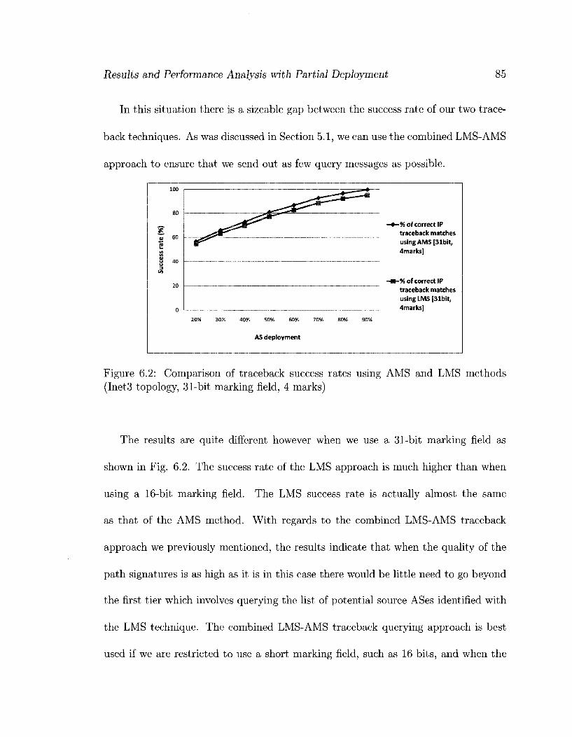
Results and Performance Analysis with Partial Deployment 85
In this situation there is a sizeable gap between the success rate of our two trace-
back techniques. As was discussed in Section 5.1, we can use the combined LMS-AMS
approach to ensure that we send out as few query messages as possible.
100
80
"Z 60 2 i n
u 40 3
20
0
20% 30% 40% 50% 60% 70%
AS deployment
Z Z i S ^ - ' " * —
80% 90%
-*-% of correct IP traceback matches using AMS [31bit, 4marks]
-m-% of correct IP traceback matches using LMS [31bit, 4marks]
Figure 6.2: Comparison of traceback success rates using AMS and LMS methods (Inet3 topology, 31-bit marking field, 4 marks)
The results are quite different however when we use a 31-bit marking field as
shown in Fig. 6.2. The success rate of the LMS approach is much higher than when
using a 16-bit marking field. The LMS success rate is actually almost the same
as that of the AMS method. With regards to the combined LMS-AMS traceback
approach we previously mentioned, the results indicate that when the quality of the
path signatures is as high as it is in this case there would be little need to go beyond
the first tier which involves querying the list of potential source ASes identified with
the LMS technique. The combined LMS-AMS traceback querying approach is best
used if we are restricted to use a short marking field, such as 16 bits, and when the

Results and Performance Analysis with Partial Deployment 86
path signatures are not nearly as unique as they are in this case.
6.2 Effect of Topology
As mentioned in Section 4.1.1, besides the Inet3 generated topology we also used a
topology generated with Brite which gave us a longer average AS-path length. This
longer path length should be better representative of the current Internet average
AS-path length.
We have evaluated the difference in performance of our scheme between the two
topologies when using a 31-bit marking field. Based on the data in table 6.2, when
using the Brite topology the potential source AS can be narrowed down to fewer
ASes. However, the traceback success rate is somewhat lower with the Brite topology
as illustrated in figures 6.3 and 6.4.
Traceback technique LMS AMS
Avg # of potential source ASes (Inet3) 5.6 21.5
Avg # of potential source ASes (Brite) 3 13.4
Table 6.2: Comparing traceback results between the Inet3 and Brite topologies (31-bit marking field, 4 marks)

Results and Performance Analysis with Partial Deployment 87
20% 30% 40% 50% 60% 70% 80% 90%
AS deployment
—*—% of correct IP traceback matches using AMS [Inet3, 31bit, 4marks]
-m-% of correct IP traceback matches using AMS [Brite, 31bit, 4marks]
Figure 6.3: Comparing AMS traceback success rates between Inet3 and Brite topologies (4 marks)
(%)
rate
ce
ss
3
..
100
80
60
40
20
0
-+-% of correct IP traceback matches using LMS [Inet3, 31bit, 4marks]
-m-% of correct IP traceback matches using LMS [Brite, 31bit, 4marks]
20% 30% 40% 50% 60% 70% 80% 90%
AS deployment
Figure 6.4: Comparing LMS traceback success rates between Inet3 and Brite topologies (4 marks)

Results and Performance Analysis with Partial Deployment 88
6.3 Varying the Number of Marks Recorded
In this section we evaluate the effects of varying the number of total marks stored
in the packet using both the Brite and Inet3 topologies. Given a fixed-size marking
field, increasing the number of marks means decreasing the number of bits per mark.
In tables 6.3 and 6.4 we show how many ASes on average the potential source AS can
be narrowed down to out of all possible 4999 ASes in each of our two topologies.
Traceback technique
LMS AMS
Avg # of potential source ASes (4 marks) 3 13.4
Avg # of potential source ASes (5 marks) 2.5 15
Avg # of potential source ASes (6 marks) 3.3 27
Table 6.3: Traceback results with partial deployment (Brite topology with 5000 ASes, 4 to 6 marks)
Traceback technique
LMS AMS
Avg # of potential source ASes (3 marks) 96.3 141.10
Avg # of potential source ASes (4 marks) 5.6 21.4
Avg # of potential source ASes (5 marks) 7.2 29.0
Avg # of potential source ASes (6 marks) 11.8 54.2
Table 6.4: Traceback results with partial deployment (Inet3 topology with 5000 ASes, 3 to 6 marks)
The data in table 6.3 indicates that choosing to allow 5 marks in the packet header
gives the most accurate results with the Brite topology. This number of marks results
in the lowest number of potential source ASes when using the LMS technique. It
should be noted that this choice most closely matches the mean distance of the Brite
topology which was found to be 4.76. When using the AMS technique, the number

Results and Performance Analysis with Partial Deployment 89
of potential source ASes identified using 5 marks is only slightly higher than when
using 4 marks. Our best choice still remains 5 marks however, because in this case
LMS results are more important than AMS results. The reason for this will become
more clear later on in this section when we compare the success rate of LMS versus
AMS.
The data in table 6.4 indicates that choosing to place 4 marks in the packet header
is the best option when using the Inet3 topology. This choice results in the fewest
potential source ASes identified using either one of our two traceback techniques. The
mean distance of the Inet3 topology was found to be 3.54. Hence, once again our
choice most closely matches the mean distance of the topology being used. This set
of tests included a case with 3 marks whereas the tests with the Brite topology did
not include this number of marks. The reason for this is that it was desired to have
at least one case with fewer marks than the mean distance of the topology.
Now that we have looked at choosing the ideal number of marks in the packet
based on the number of potential ASes identified, let us look at another set of results
and see if we arrive at the same conclusions. Fig. 6.5 illustrates, using the Brite
topology, how the rate of successfully identifying the true origin AS among the list
of potential ASes obtained using the LMS approach varies with the deployment rate.
The success rate using only the AMS technique is by design the same among the
different simulations run on the same topology. Based on these results, choosing to
allow 5 marks in the packet header gives the most accurate results. As is evident, our
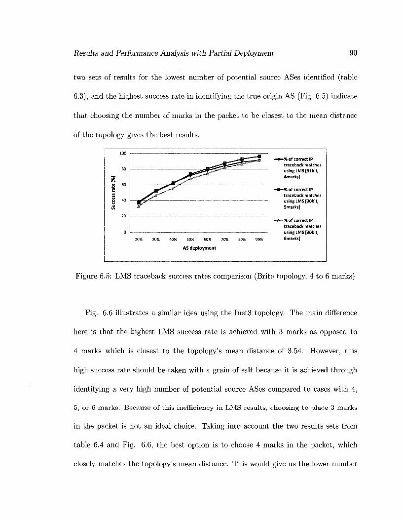
Results and Performance Analysis with Partial Deployment 90
two sets of results for the lowest number of potential source ASes identified (table
6.3), and the highest success rate in identifying the true origin AS (Fig. 6.5) indicate
that choosing the number of marks in the packet to be closest to the mean distance
of the topology gives the best results.
100
80
o 60
2 (A
8 40 3
I/)
20
0
20% 30% 40% 50% 60% 70% 80% 90% 6marks]
AS deployment
Figure 6.5: LMS traceback success rates comparison (Brite topology, 4 to 6 marks)
Fig. 6.6 illustrates a similar idea using the Inet3 topology. The main difference
here is that the highest LMS success rate is achieved with 3 marks as opposed to
4 marks which is closest to the topology's mean distance of 3.54. However, this
high success rate should be taken with a grain of salt because it is achieved through
identifying a very high number of potential source ASes compared to cases with 4,
5, or 6 marks. Because of this inefficiency in LMS results, choosing to place 3 marks
in the packet is not an ideal choice. Taking into account the two results sets from
table 6.4 and Fig. 6.6, the best option is to choose 4 marks in the packet, which
closely matches the topology's mean distance. This would give us the lower number
- X ^ " ^i'
*^Z
SsS* —rrii
^ ^
-% of correct IP traceback matches using LMS [31bit, 4marks]
-% of correct IP traceback matches using LMS [30bit, 5marks]
-% of correct IP traceback matches

Results and Performance Analysis with Partial Deployment 91
of potential source ASes identified, with a very high success rate.
100
80
V 60
2 (A Iff
S 40 u 3 */>
20
0
20% 30% 40% 50% 60% 70% 80% 90%
AS deployment
Figure 6.6: LMS traceback success rates comparison (Inet3 topology, 3 to 6 marks)
In section 6.1, for the case involving the Inet3 topology with a 31-bit marking field
(Fig. 6.2), we concluded that the success rate of the LMS technique is very close to
that of the AMS technique. Therefore, there is negligible gain in using the combined
LMS-AMS traceback approach in such a situation. We have a similar situation with
the Brite topology as illustrated in Fig. 6.7. Since it is almost completely sufficient to
use just the LMS technique in this situation, we can place our emphasis on the LMS
results when deciding what metrics to choose such as the most appropriate number
of marks allowed in the packet header.
-% of correct IP traceback matches using LMS [30bit, 3marks]
-% of correct IP traceback matches using LMS [31bit, 4marks]
-% of correct IP traceback matches using LMS [30bit, Smarks]
-% of correct IP traceback matches using LMS [30bit,

Results and Performance Analysis with Partial Deployment 92
-% of correct IP traceback matches using AMS [30bit, 5marks]
-% of correct IP traceback matches using LMS [30bit, 5marks]
20% 30% 40% 50% 60% 70% 80% 90%
AS deployment (Brite topology, 30bit marking field, 6bits per AS mark, 5 marks in total)
Figure 6.7: Comparison of traceback success rates using AMS and LMS. methods (Brite topology, 30-bit marking field, 5 marks)
6.4 Effect of Marking Field on Learning Path Sig
natures
In this section we analyze the number of path signature id reply packets required in
order to form valid path signatures in our simulations. What we expect is that as
the number of bits used per AS mark increases, the number of path signature id reply
packets required decreases. We expect this because with longer AS marks, it would
be much more difficult for any random initial data in the marking field to exactly
match an AS mark across multiple path signature id reply packets.
Inet3 Topology:

Results and Performance Analysis with Partial Deployment
• 31-bit marking field, 7bits/AS, 4 marks = > 4 packets
• 30-bit marking field, 6bits/AS, 5 marks =>• 5 packets
• 30-bit marking field, 5bits/AS, 6 marks = » 5 packets
• 16-bit marking field, 4bits/AS, 4 marks => 6 packets
• 31-bit marking field, 7bits/AS, 4 marks + 3 partial bits
93
7 packets
Brite Topology:
• 31-bit marking field, 7bits/AS, 4 marks ==> 4 packets
• 30-bit marking field, 6bits/AS, 5 marks = > 5 packets
• 30-bit marking field, 5bits/AS, 6 marks =>• 5 packets
• 31-bit marking field, 7bits/AS, 4 marks + 3 partial bits 6 packets
Given the data here, we can confirm our expectation that the more bits used per
AS mark, the fewer path signature id reply packets required. The higher number of
packets needed when using 7 bits per AS mark to record 4 full marks, along with
3 partial bits of the 5th mark is due to those partial bits. When the same set of
simulations results are analyzed without taking those 3 partial bits into account,
fewer path signature id reply packets are required.

Chapter 7
Conclusions and Future Work
7.1 Conclusions
The hierarchical solution we have developed provides a means carrying out IP trace-
back at the AS-level, while allowing for incremental deployment. It can also enable
filtering incoming attack packets at the network edge, and detecting spoofed IP pack
ets. Our solution can work on both live incoming traffic, as well as on previously
captured packets.
In our discussions, we suggested a means of using more fragmentation related
bits in the IPv4 header than what is typically used in current proposed IP traceback
schemes. We proposed two different methods for carrying out IP traceback in our
solution. These were the All Matching Signatures and Longest Matching Signature
techniques.
94

Conclusions and Future Work 95
We carried out a number of simulation experiments in scenarios with both full
deployment, and partial deployment of our solution. We used two separate topologies
in our tests. We tested the effects of varying the sizes of the marking field, varying
the number of total AS marks, as well as using different sizes for each AS mark.
Our simulation results showed that we can recover signatures for a large number
of legacy ASes and that we can perform traceback with good accuracy in the presence
of legacy ASes. We concluded that the most appropriate choice for the number of
marks to allocate in a packet is that which corresponds to the average AS path
length of the topology. We observed that increasing the size of each AS mark has a
far more significant effect on the accuracy of the results compared to increasing the
total number of marks.
When the length of the marking field is small, 16 bits for example, we observed a
sizeable gap between the success rates of our two traceback techniques. We concluded
that the best approach in such a situation is to use a combined LMS-AMS technique to
ensure that we send out as few query messages to potential source ASes as possible.
With longer marking fields, in the range of 31 bits, we noticed the gap between
the success rates of the two traceback techniques becomes much narrower. Thus,
we concluded that in such situations using only the LMS technique would likely be
sufficient.
We believe the numerous strong points mentioned should make our solution a
good candidate for future adoption, or serve as the basis for future work in this area.

Conclusions and Future Work 96
7.2 Future Research
In this thesis we presented results based on simulations. Our research can benefit
from analytical evaluation as well. Particularly in terms of determining the minimum
number of path signature id reply packets that should be sent so that the recipient
can distinguish valid marking bits from initial random data in the marking field.
Our research was primarily centered around IP traceback. Hence, we used a very
simple signature distribution mechanism for our simulations. We did not test the
candidate signature distribution algorithms we proposed in Section 3.7. This is an
area which can be the focus of further research and fine-tuning.
Within the context of signature distribution, we mentioned a number of variables,
the fine-tuning of which can be the subject of future research. These variables were
as follows:
• t, which is the minimum time delay between sending path signature id reply
packets to the same destination AS
• k time units, at every countdown of which the dedicated server will send out
path signature id reply messages to an AS

Appendix A
NS-2 Modification Summary
In table A.l we list all the ns-2 files modified in order to implement our solution. We
also provide a brief description of why each file was modified.
Filename
astackpisig.ee
astackpisig.h
ast ackpisigsink. cc
ast ackpisigsink. h
Location
/apps
/apps
/apps
/apps
Reason for Modification Newly added agent to construct and initialize our simulation packets. Functionalities such as randomizing the contents of the IP identification field are performed here. Newly added header file for astackpisig.ee Newly added traffic sink agent to consume our simulation packets and write fields of interest to a log file for later analysis. This would include information on the type of packet, such as a spoofed packet, normal packet, or one meant to be used for learning path signatures. The marking field of the packet would also be written to the log file. The source AS number, and whether or not it is a legacy AS would also be recorded. Newly added header file for astack-pisigsink.ee
97

NS-2 Modification Summary 98
classifier, cc
classifier, h
ip.h
node.cc
node.h
ns-default.tcl
ns-node.tcl
/classifier
/classifier
/common
/common
/common
/tcl/lib
/tcl/lib
Added a considerable amount of code to recv function to perform the actual packet marking according to our solution design. The Classifier class is the most important class in ns2 as far as our solution is concerned. If we were to approximate how ns2 simulations run as compared to the operations in a real physical network, the Classifier class performs forwarding functionalities in a router. The functionalities of the ingress and egress routers discussed in our solution, and generating signatures on behalf of legacy AS neighbours are all done in this class.
Added additional variable to keep track of which node this classifier object is associated with Added several new fields to each IP packet such as the actual marking field, and others to help make implementation easier by keeping track of the simulation stage, or to record the full route taken by the packet thus far, etc. Added code to keep track of whether or not this node supports our solution Added code to keep track of whether or not this node supports our solution Modifications needed to support newly added agents. These had to do with the default values some of the variables in a new instance of our agent would be initialized with upon creation. Modified so that each node keeps track of its direct neighbours. Useful in legacy situation where a solution-supporting node needs to generate signatures on behalf of its neighbouring legacy ASes.

NS-2 Modification Summary 99
rtmodule.cc /routing
Added code to make it much easier to tell which node a classifier object belonged to. When first working with ns2 Classifier code, a big difficulty we had was that there was no easy way of telling which simulation node the Classifier code was executing on behalf of.
simulator.h /common Initialize random number generator when the simulation starts
Makefile / Include new agent files for compilation Table A.l: List of all ns-2 files modified to implement our design

Bibliography
[1] IANA AS Registry. [Online]. Available: http:/ /www.iana.org/assignments/
as-numbers/, (Jan. 2009).
[2] Internet Assigned Numbers Authority. [Online]. Available: http://www.iana.
org, (Jan. 2009).
[3] RIPE NCC - RIS Statistics Report. [Online]. Available: h t t p : / /www.r is . r ipe .
net /weekly-report / , (Jan. 2009).
[4] Team Cymru - IP to ASN Mapping. [Online]. Available: http://www.
team-cymru.org/Services/ip-to-asn.html, (Jan. 2009).
[5] Team Cymru Internet Monitor - BGP Average AS-Path Length. [Online]. Avail
able: http://www.cymru.com/BGP/avg_aspath_len.html, (Jan. 2009).
[6] The CIDR Report. [Online]. Available: h t tp: / /www.potaroo.net /cgi-bin/
as-report?as=, (Jan. 2009).
100

Bibliography 101
[7] The Network Simulator - ns-2. [Online]. Available: h t tp : / /www.is i .edu/
nsnam/ns/, (Jan. 2009).
[8] IPv6 Extension Headers Review and Considerations, October 2006. [On
line]. Available: http://www.cisco.com/en/US/teclinologies/tk648/tk872/
technologies_white_paper0900aecd8054d37d.html, (Jan. 2009).
[9] TCP Intercept, 2007. Cisco IOS Security Configuration Guide, Release 12.2. [On
line]. Available: h t t p : //www. c isco. com/en/US/docs/ios/12_2/security/
configuration/guide/scfdenl.html, (Jan. 2009).
[10] Unicast Reverse Path Forwarding, 2007. Cisco IOS Security Configuration
Guide, Release 12.2. [Online]. Available: http://www.cisco.com/en/US/docs/
ios /12_2/secur i ty /conf igurat ion/guide/scfrpf .html , (Jan. 2009).
[11] The Linux Kernel Archives - Version 2.6.26, 2008. [Online]. Available: h t t p :
/ /www.kernel .org/pub/l inux/kernel/v2.6/ , (Jan. 2009).
[12] E. Albright and X. Dang. An Implementation of IP Traceback in IPv6 Using
Probabilistic Packet Marking. PhD thesis, The University of Akron, 2005.
[13] S.O. Amin, M.S. Kang, and C.S. Hong. A Lightweight IP Traceback Mechanism
on IPv6, volume 4097 of Lecture Notes in Computer Science. Springer Berlin,
2006.

Bibliography 102
[14] A. Belenky and N. Ansari. On IP Traceback. Communications Magazine, IEEE,
41(7):142 153, 2003.
[15] A. Belenky and N. Ansari. Tracing Multiple Attackers with Deterministic Packet
Marking (DPM). Communications, Computers and signal Processing, 2003.
PACRIM. 2003 IEEE Pacific Rim Conference on, 1:49-52, Aug. 2003.
[16] S.M. Bellovin, M. Leech, and T. Taylor. ICMP Traceback Messages,
March 2000. [Online]. Available: h t t p : / / l a s r . c s . u c l a . e d u / s a v e / r f c /
d ra f t -be l lov in- i t race-OO. tx t , (Jan. 2009).
[17] Burton H. Bloom. Space/Time Trade-offs in Hash Coding with Allowable Errors.
Commun. ACM, 13(7):422-426, 1970.
[18] A. Bremler-Barr and H. Levy. Spoofing Prevention Method. In INFOCOM
2005. 24th Annual Joint Conference of the IEEE Computer and Communications
Societies. Proceedings of the IEEE, pages 536-547, Mar. 2005.
[19] H. Burch and B. Cheswick. Tracing Anonymous Packets to Their Approximate
Source. In LISA '00: Proceedings of the 14th USENIX conference on System
administration, pages 319-328, Berkeley, CA, USA, 2000. USENIX Association.
[20] K. Butler and W. Aiello. Optimizing BGP security by exploiting path stability.
In Proceedings of the 13th ACM conference on Computer and communications
security, pages 298-310. ACM Press New York, NY, USA, 2006.

Bibliography 103
[21] Andre O. Castelucio, Ronaldo M. Salles, and Artur Ziviani. An AS-level IP
Traceback System. In CoNEXT '07: Proceedings of the 2007 ACM CoNEXT
conference, pages 1-2, New York, NY, USA, 2007. ACM.
[22] A. Dabir and A. Matrawy. Design and Analysis of a Hierarchical IP Traceback
System. To be published in IEEE International Conference on Communications
(ICC'09), June 2009.
[23] A. Dabir and A. Matrawy. Packet Tracing and Detection of Source-Spoofing
Across Multiple Autonomous Systems. Manuscript submitted to a journal for
review.
[24] E. Decker, P. Langille, A. Rijsinghani, and K. McCloghrie. Definitions of Man
aged Objects for Bridges. Internet Request for Comments RFC 1493, 1993.
[25] S. Deering and R. Hinden. Internet Protocol, Version 6 (IPv6) Specification.
Internet Request for Comments RFC 2460, 1998.
[26] P. Ferguson and D. Senie. Network Ingress Filtering: Defeating Denial of Ser
vice Attacks which employ IP Source Address Spoofing. Internet Request for
Comments RFC 2827, 2000.
[27] Z. Gao and N. Ansari. Tracing Cyber Attacks from the Practical Perspective.
Communications Magazine, IEEE, 43(5):123-431, 2005.

Bibliography 104
[28] C. Gong, T. Le, T. Korkmaz, and K. Sarac. Single Packet IP Traceback in AS-
level Partial Deployment Scenario. In Global Telecommunications Conference,
2005. GLOBECOM'05. IEEE, pages 1817-1821, Nov. 2005.
[29] G. Goodell, W. Aiello, T. Griffin, J. Ioannidis, P. McDaniel, and A. Rubin. Work
ing Around BGP: An Incremental Approach to Improving Security and Accuracy
of Interdomain Routing. In In The 10th Annual Network and Distributed System
Security Symposium (NDSS03), 2003.
[30] I. Hamadeh and G. Kesidis. A Taxonomy of Internet Traceback. International
Journal of Security and Networks, 1(1):54-61, 2006.
[31] J. Hawkinson and T. Bates. Guidelines for creation, selection, and registration of
an autonomous system (AS). Internet Request for Comments RFC 1930, 1996.
[32] H. Hazeyama, M. Oe, and Y. Kadobayashi. A Layer-2 Extension to Hash-Based
IP Traceback. IEICE Transactions on Information and Systems, 86(11):2325-
2333, 2003.
[33] S. Kent, C. Lynn, and K. Seo. Secure Border Gateway Protocol (Secure-BGP).
IEEE Journal on Selected Areas in Communications, 18(4):582-592, 2000.
[34] T. Killalea. Recommended internet service provider security services and proce
dures. Internet Request for Comments RFC 3013, 2000.
Bibliography 105
[35] Y. Kim, J.Y. Jo, and FL Merat. Defeating Distributed Denial-of-Service At
tack with Deterministic Bit Marking. In Global Telecommunications Conference,
2003. GLOBECOM'03. IEEE, pages 1363-1367, Dec. 2003.
[36] Craig Labovitz. 2008 Worldwide Infrastructure Security Report, Novem
ber 2008. [Online]. Available: h t tp : / / aser t . a rborne tworks .com/2008/ l l /
2008-worldwide- infras t ructure-securi ty-report / , (Jan. 2009).
[37] Rafael P. Laufer, Pedro B. Velloso, Daniel de O. Cunha, Igor M. Moraes, Marco
D. D. Bicudo, Marcelo D. D. Moreira, and Otto Carlos M. B. Duarte. Towards
Stateless Single-Packet IP Traceback. In LCN '07: Proceedings of the 32nd IEEE
Conference on Local Computer Networks (LCN 2007), pages 548-555, Washing
ton, DC, USA, 2007. IEEE Computer Society.
[38] D. Magoni. nem: A Software for Network Topology Analysis and Modeling. In
Proceedings of the 10th IEEE Symposium on Modeling, Analysis and Simulation
of Computer & Telecomm. Systems (MASCOTS02), pages 364-371.
[39] A.M. Mankin, D.C.L.W. Wu, and S.F.L. Zhang. On Design and Evaluation of
"Intention-Driven" ICMP Traceback. In Computer Communications and Net
works, 2001. Proceedings. Tenth International Conference on, pages 159-165,
2001.
[40] A. Medina, A. Lakhina, I. Matta, and J. Byers. BRITE: An Approach to Univer
sal Topology Generation. In Modeling, Analysis and Simulation of Computer and

Bibliography 106
Telecommunication Systems, 2001. Proceedings. Ninth International Symposium
on, pages 346-353, 2001.
[41] J. Mirkovic. A Taxonomy of DDoS Attack and DDoS Defense Mechanisms. ACM
SIGCOMM Computer Communication Review, 34(2):39-53, 2004.
[42] K. Park and H. Lee. On the Effectiveness of Route-Based Packet Filtering for
Distributed DoS Attack Prevention in Power-Law Internets. In Proceedings of
the 2001 conference on Applications, technologies, architectures, and protocols
for computer communications, pages 15-26. ACM New York, NY, USA, 2001.
[43] J. Postel. Internet Protocol. Internet Request for Comments RFC 791, Sept.
1981.
[44] J. Rajahalme, A. Conta, B.E. Carpenter, and S.E. Deering. IPv6 Flow Label
Specification. Internet Request for Comments RFC 3697.
[45] T. Rehman. Implementation of Radix Tree, March 2008. [Online]. Available:
h t tp : / /code .google .eom/p/ radix t ree / , ( Jan . 2009).
[46] Y. Rekhter, T. Li, and S. Hares. A Border Gateway Protocol 4 (BGP-4). Internet
Request for Comments RFC 4271, 2006.
[47] R. Rivest. The MD5 Message-Digest Algorithm. Internet Request for Comments
RFC 1321, 1992.

Bibliography 107
[48] S. Sangli, D. Tappan, and Y. Rekhter. BGP Extended Communities Attribute.
Internet Request for Comments RFC 4360, 2006.
[49] S. Savage, D. Wetherall, A. Karlin, and T. Anderson. Practical Network Support
for IP Traceback. In SIGCOMM '00: Proceedings of the conference on Applica
tions, Technologies, Architectures, and Protocols for Computer Communication,
pages 295-306, New York, NY, USA, 2000. ACM.
[50] AC Snoeren, C. Partridge, LA Sanchez, CE Jones, F. Tchakountio, B. Schwartz,
ST Kent, and WT Strayer. Single-Packet IP Traceback. Networking, IEEE/ACM
Transactions on, 10(6):721-734, 2002.
[51] D.X. Song and A. Perrig. Advanced and Authenticated Marking Schemes for
IP Traceback. In INFO COM 2001. Twentieth Annual Joint Conference of the
IEEE Computer and Communications Societies. Proceedings. IEEE, pages 878-
886, 2001.
[52] J. Stewart, T. Bates, R. Chandra, and E. Chen. Using a Dedicated AS for Sites
Homed to a Single Provider. Internet Request for Comments RFC 2270, 1998.
[53] WT Strayer, CE Jones, F. Tchakountio, and RR Hain. SPIE-IPv6: Single IPv6
Packet Traceback. In Local Computer Networks, 200J^. 29th Annual IEEE Inter
national Conference on, pages 118-125, 2004.

Bibliography 108
[54] T. Wan, E. Kranakis, and P. van Oorschot. Pretty Secure BGP (psBGP).
In In The 12th Annual Network and Distributed System Security Symposium
(NDSS05), 2005.
[55] T. Wan, P. VAN Oorschot, and E. Kranakis. A Selective Introduction to Border
Gateway Protocol (BGP) Security Issues. In Proc. of NATO Advanced Studies
Institute on Network Security and Intrusion Detection, 2007.
[56] R. White. Securing BGP through secure origin BGP (soBGP). The Internet
Protocol Journal, 6(3):15-22, 2003.
[57] J. Winick and S. Jamin. Inet-3.0: Internet topology generator. Technical report,
2002.
[58] A. Yaar, A. Perrig, and D. Song. FIT: Fast Internet Traceback. In INFOCOM
2005. 24th Annual Joint Conference of the IEEE Computer and Communications
Societies. Proceedings IEEE, pages 1395-1406, 2005.
[59] A. Yaar, A. Perrig, and D. Song. StackPi: New Packet Marking and Filtering
Mechanisms for DDoS and IP Spoofing Defense. Selected Areas in Communica
tions, IEEE Journal on, 24(10):1853-1863, 2006.