design and analysis of four wheeler airless tire - ijatir · design and analysis of four wheeler...
TRANSCRIPT
www.ijatir.org
ISSN 2348–2370
Vol.08,Issue.22,
December-2016,
Pages:4298-4305
Copyright @ 2016 IJATIR. All rights reserved.
Design and Analysis of Four Wheeler Airless Tire S. SHASHAVALI
1, C. RAGHUNATHA REDDY
2, GANESH KUMAR YADIKI
3
1PG Scholar, Dept of Mechanical Engineering, Tadipatri Engineering College, AP, India.
2Assistant Professor, Dept of Mechanical Engineering, Tadipatri Engineering College, AP, India.
3Managing Partner, Southern Geometrics, Anantapuram, AP, India.
Abstract: The airless tire is a single unit replacing the
pneumatic tire, wheel and tire assembly. It replaces all the
components of a typical radial tire and is comprised of a
rigid hub, connected to a shear band by means of flexible,
deformable polyurethane spokes and a tread band, all
functioning as a single unit. The Tweel, a kind of airless tire,
though finds its generic application in military and earth
moving applications due to its flat proof design can also
render the pneumatic tire obsolete in domestic cars. Our
project involves design and analysis of an airless tire for
domestic cars; this will be followed by a stress analysis
study. The model will be do in Pro E and analysis will do in
Ansys.
Keywords: Tire Parameters, Pro/E and Ansys.
I. INTRODUCTION
The Tweel (a portmanteau of tire and wheel) is an
airless tire design concept developed by the French tire
company Michelin. Its significant advantage over pneumatic
tires is that the Tweel does not use a bladder full
of compressed air, and therefore it cannot burst, leak
pressure, or become flat. Instead, the Tweel assembly's inner
hub connects to flexible polyurethane spokes which are used
to support an outer rim and these engineered compliant
components assume the shock-absorbing role provided by
the compressed air in a traditional tire. Sometimes, we get so
used to a certain product that no true changes are ever really
made for years, decades even. So begins an article discussing
the development of airless tires, something that has become
more prevalent in the past few years. A few tire companies
have started experimenting with designs for non pneumatic
tires including Michelin and Bridgestone, but neither design
has made it to mass production. Creating a new non
pneumatic design for tires has more positive implications
than one might think. For one thing, there are huge safety
benefits. Having an airless tire means there is no possibility
of a blowout, which, in turn, means the number of highway
accidents will but cut significantly. Even for situations such
as Humvees in the military, utilizing non pneumatic tires has
a great positive impact on safety. Tires are the weak point in
military vehicles and are often targeted with explosives. If
these vehicles used airless tires, this would no longer be a
concern. There is also an environmental benefit to using this
type of tire. Since they never go flat and can be retreaded,
airless tires will not have to be thrown away and replaced
nearly as often as pneumatic tires. This will cut down landfill
mass significantly. Because of the benefits, I believe that it is
extremely important that research and production of airless
tires is continued and increased. This type of innovation
works well in conjunction with several engineering codes of
ethics, and thus should be embraced by engineers
everywhere. Cars are things that people use every day, so
any improvements over existing designs would affect the
lives of the majority of people. Learning about such a topic,
therefore, I believe holds extreme value especially for us
freshmen engineering students. In doing research into these
kinds of topics that hold significant meaning, I can see that
what we will do can make a difference.
II. LITERATURE SURVEY Sadok Sassi, Mohamed Ebrahemi, Musab Al Mozien and
Yousef El Hadary [1], modern pneumatic tires (PT) are the
results of enormous progress in science, technology, and
manufacturing process. However, they are still subjected to
adverse problems that could compromise the road safety and
lead to accidents of different severities. Vinay T V,
Kuriakose J Marattukalam, Sachu Zachariah Varghese,
Shibin Samuel, Sooraj Sreekumar [2], a pneumatic tyre is
made of an airtight inner core filled with pressurized air.
Pneumatic tyres have been dominant in the world market due
to many advantages like low mass design, low vertical
stiffness and low contact pressure. Rutika Gotad, Sukanya
Yadav , Aarti Dung [3], the paper introduces the new
advanced developing tire technology which is used mainly in
automobile industry. As we come across different types of
accidents in our day to day life so in order to avoid such
accidents, we had developed new technology as tweel tyre.
Raymond R. Ma, Joseph T. Belter, Aaron M. Dollar [4], this
paper describes a novel fabrication technique called hybrid
deposition manufacturing (HDM), which combines additive
manufacturing (AM) processes such as fused deposition
manufacturing (FDM) with material deposition and
embedded components to produce multi material parts and
systems for robotics, mechatronics, and articulated
mechanism applications. Rathindra Nath Biswas, Mohit
Ojha and Arijeet Bhadra [5], a lot of new challenges are
being posed in front of the automobile industry by the
growing customer demands. Tire puncture is a common
problem in Automotive Vehicles. We are thinking of a tire
S. SHASHAVALI, C. RAGHUNATHA REDDY, GANESH KUMAR YADIKI
International Journal of Advanced Technology and Innovative Research
Volume. 08, IssueNo.22, December-2016, Pages: 4298-4305
which is airless. It is made up of a combination of different
types of rubber. K.Periasamya, S.Vijayan [6], In this work,
models of air-less tire is constructs to simulate the loading
condition. The driver mind-stress may reduce by using air-
less tire in automobile field by avoiding air related problems
in the tire. Mean while uniform traction and wear as possible
to use air-less tire. Air-less tire, air-tire are modeled by
SOLID-WORKS modeling software. John Gordon, BS,
James J. Kaualarich, PhD, and John G. Thacker, PhD [13], the
performance characteristics of four 24 inch wheelchair tires
are considered; one pneumatic and three airless. Specifically,
two new airless polyurethane foam tires (circular and tapered
cross-section) were compared to both a molded poly
isoprene tire and a rubber pneumatic tire.
III. MATERIALS
A. Introduction
A composite material is usually made up of at least two
materials out of which one is the binding material, also
called matrix and the other is the reinforcement material. By
definition, composite materials consist of two or more
constituents with physically separable phases. Composites
are materials that comprise strong load carrying material
(known as reinforcement) imbedded in weaker material
(known as matrix). Reinforcement provides strength and
rigidity, helping to support structural load. The matrix or
binder maintains the position and orientation of the
reinforcement. Significantly, constituents of the composites
retain their individual, physical and chemical properties yet
together they produce a combination of qualities which
individual constituents would be incapable of producing
alone. The reinforcement may be platelets, particles or fibers
and are usually added to improve mechanical properties such
as stiffness, strength and toughness of the matrix material.
B. Overview of Composite Materials
Composites are made up of individual materials referred
to as constituent materials. There are two main categories of
constituent materials: matrix and reinforcement. At least one
portion of each type is required. The matrix material
surrounds and supports the reinforcement materials by
maintaining their relative positions. The reinforcements
impart their special mechanical and physical properties to
enhance the matrix properties. A synergism produces
material properties unavailable from the individual
constituent materials, while the wide variety of matrix and
strengthening materials allows the designer of the product or
structure to choose an optimum combination. Engineered
composite materials must be formed to shape. The matrix
material can be introduced to the reinforcement before or
after the reinforcement material is placed into the
mould cavity or onto the mould surface. The matrix material
experiences a melding event, after which the part shape is
essentially set. Depending upon the nature of the matrix
material, this melding event can occur in various ways such
as chemical polymerization or solidification from the melted
state. A variety of molding methods can be used according to
the end-item design requirements. The principal factors
impacting the methodology are the natures of the chosen
matrix and reinforcement materials.
C. Polyethylene
This Polyolefin is readily formed by polymerizing
propylene with suitable catalysts, generally aluminum alkyl
and titanium tetrachloride. Polypropylene properties vary
according to molecular weight, method of production, and
the copolymers involved. Generally polypropylene has
demonstrated certain advantages in improved strength,
stiffness and higher temperature capability over
polyethylene. Polypropylene has been very successfully
applied to the forming of fibers due to its good specific
strength which is why it is the single largest use of
polyethylene. Polyethylene also happens to be one of
lightest plastics available with a density of 0.905 g/cm2.
1. Advantages
Homo polymer
Process ability, Good
Food Contact Acceptable
Stiffness, Good
Impact Resistance, Good
Copolymer
Flow, High
Impact Resistance, High
Chemically Coupled
2. Disadvantages and Limitations
Degraded by UV
Flammable, but retarded grades available
Attacked by chlorinated solvents and aromatics
Difficult to bond
Several metals accelerate oxidative degrading
Low temperature impact strength is poor
3. Typical Applications
Automotive Applications
Household Goods
Film
Containers
Appliances
Packaging
Electrical/Electronic Applications
Industrial Applications
General Purpose
TABLE I
IV. INTRODUCTION TO DESIGN
A. Computer Aided Design (CAD)
Computer Aided Design (CAD) is the use of wide range
of computer based tools that assist engineering, architects
Design and Analysis of Four Wheeler Airless Tire
International Journal of Advanced Technology and Innovative Research
Volume. 08, IssueNo.22, December-2016, Pages: 4298-4305
and other design professionals in their design activities. It is
the main geometry authoring tool within the product life
cycle management process and involves both software and
sometimes special purpose hardware. Current packages
range from 2D vector based drafting systems to 3D
parametric surface and solid design models.
B. Introduction
CAD is used to design and develop products, which can
be goods used by end consumers or intermediate goods used
in other products. CAD is also extensively used in the design
of tools and machinery used in the manufacturer of
components. CAD is also used in the drafting and design of
all types of buildings, from small residential types (house) to
the largest commercial and industrial types. CAD is used
thought the engineering process from the conceptual design
and layout, through detailed engineering and analysis of
components to definition of manufacturing methods.
AutoCAD is commercial software for 2D and 3D computer-
aided design (CAD) and drafting available since 1982 as a
desk top application and since 2010 as a mobile web and
cloud based app marketed as AutoCAD 360. Developed and
marketed by Autodesk, Inc., AutoCAD was first released in
December 1982, running on micro computers with internal
graphics controllers. Prior to the introduction of AutoCAD,
most commercial CAD programs ran on main frame
computers or mini computers, with each CAD operator
(user) working at a separate graphics terminal. AutoCAD is
used across a wide range of industries, by architects, project
managers, engineers, designers, and other professionals. It is
supported by 750 training centers worldwide as of 1994.
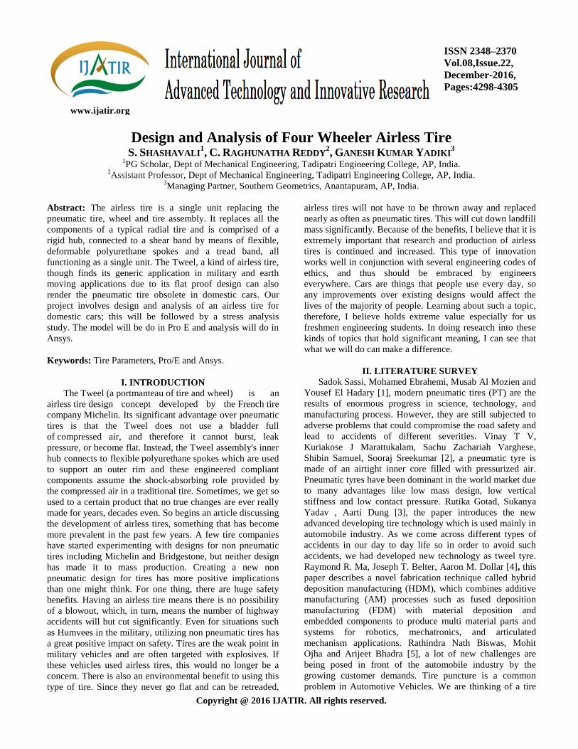
C. Introduction to PRO-E
Fig.1. Outer Rubber Portion (Tire).
PRO-E is the industry‟s de facto standard 3D mechanical
design suit. It is the world‟s leading CAD/CAM /CAE
software, gives a broad range of integrated solutions to cover
all aspects of product design and manufacturing. Much of its
success can be attributed to its technology which spurs its
customer‟s to more quickly and consistently innovate a new
robust, parametric, feature based model. Because that PRO-E
is unmatched in this field, in all processes, in all countries, in
all kind of companies along the supply chains. PRO-E is also
the perfect solution for the manufacturing enterprise, with
associative applications, robust responsiveness and web
connectivity that make it the ideal flexible engineering
solution to accelerate innovations. PRO-E provides easy to
use solution tailored to the needs of small medium sized
enterprises as well as large industrial corporations in all
industries, consumer goods, fabrications and assembly.
Electrical and electronics goods, automotive, aerospace,
shipbuilding and plant design. It is user friendly solid and
surface modeling can be done easily.
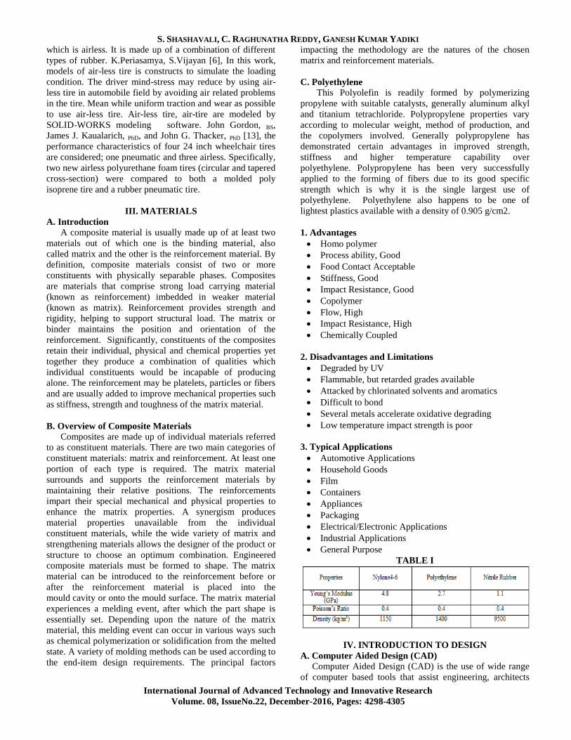
Fig.2. Detail View of Outer Rubber Portion (Tire)
V. FINITE ELEMENT METHOD / ANALYSIS
(FEM/A)
A. Introduction
The finite element method is numerical analysis technique
for obtaining approximate solutions to a wide variety of
engineering problems. Because of its diversity and flexibility
as an analysis tool, it is receiving much attention in almost
every industry. In more and more engineering situations
today, we find that it is necessary to obtain approximate
solutions to problem rather than exact closed form solution.
It is not possible to obtain analytical mathematical solutions
for many engineering problems. The finite element method
has become a powerful tool for the numerical solutions of a
wide range of engineering problems. It has been developed
simultaneously with the increasing use of the high- speed
electronic digital computers and with the growing emphasis
on numerical methods for engineering analysis. This method
started as a generalization of the structural idea to some
problems of elastic continuum problem, started in terms of
different equations. The basic idea in the Finite Element is to
find the solution of complicated problem with relatively easy
way. The Finite Element Method has been a powerful tool
for the numerical solution of a wide range of engineering
problems. Applications range from deformation and stress
analysis of automotive, aircraft, building, defense, and
missile and bridge structures to the field of analysis of
dynamics, stability, fracture mechanics, heat flux, fluid flow,
magnetic flux, seepage and other flow problems. With the
advances in computer technology and CAD systems,
complex problems can be modeled with relative ease.
S. SHASHAVALI, C. RAGHUNATHA REDDY, GANESH KUMAR YADIKI
International Journal of Advanced Technology and Innovative Research
Volume. 08, IssueNo.22, December-2016, Pages: 4298-4305
Several alternate configurations can be tried out on a
computer before the first prototype is built. The basics in
engineering field are must to idealize the given structure for
the required behavior. The proven knowledge in the typical
problem area, modeling techniques, data transfer and
integration, computational aspects of the Finite Element
Method is essential. In the Finite Element Method the
solution region is considered as built up many small,
interconnected sub regions called finite elements. Most often
it is not possible to ascertain the behavior of complex
continuous systems without some sort of approximations.
For simple members like uniform beams, plates etc.,
classical solutions like machine tool frames, pressure
vessels, automobile bodies, ships, air craft structures, domes
etc., need some approximate treatment to arrive at their
behavior, be it static deformation, dynamic properties or heat
conducting property. Indeed these are continuous systems
with their mass and elasticity being continuously distributed.
To overcome this, engineers and mathematicians have from
time to time proposed complex structure is defined using a
finite number of well defined components. Such systems are
then regarded as discrete systems. The discretization method
could be finite difference approximation, various residual
procedures etc.
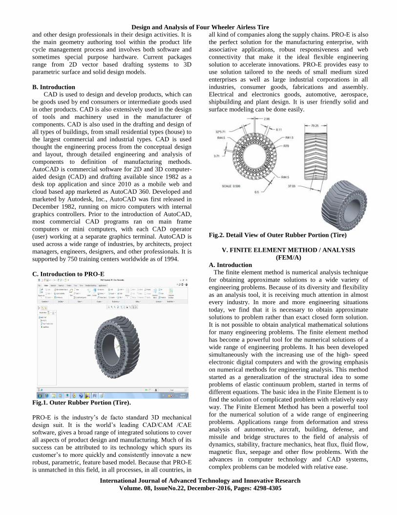
B. Importing the Model
In this step the PRO/E model is to be imported into
ANSYS workbench as follows, In utility menu file option
and selecting import external geometry and open file and
click on generate. To enter into simulation module click on
project tab and click on new simulation.
Fig.3. Imported from Pro-E
1. Defining Material Properties
To define material properties for the analysis, following
steps are used. The main menu is chosen select model and
click on corresponding bodies in tree and then create new
material enter the values again select simulation tab and
select material.
2. Defining Element Type
To define type of element for the analysis, these steps
are to be followed, Chose the main menu select type of
contacts and then click on mesh-right click-insert method
Method - Tetrahedrons
Algorithm - Patch Conforming
Element Mid side Nodes – Kept
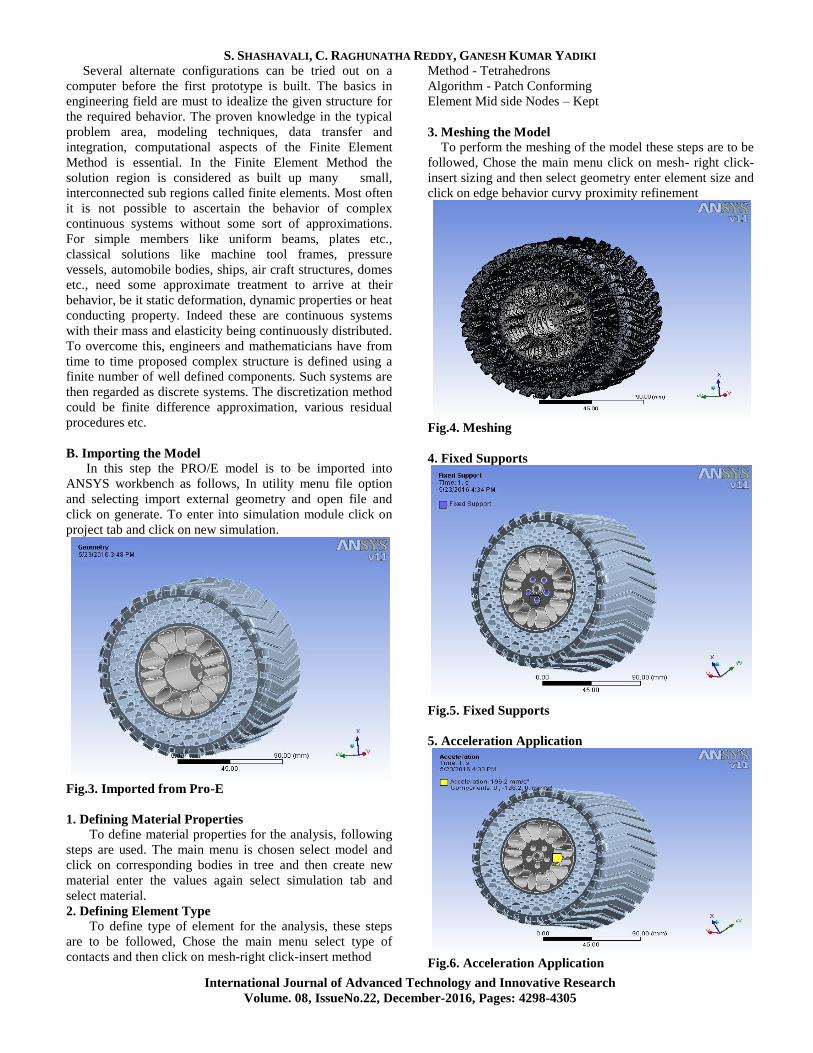
3. Meshing the Model To perform the meshing of the model these steps are to be
followed, Chose the main menu click on mesh- right click-
insert sizing and then select geometry enter element size and
click on edge behavior curvy proximity refinement
Fig.4. Meshing
4. Fixed Supports
Fig.5. Fixed Supports
5. Acceleration Application
Fig.6. Acceleration Application
Design and Analysis of Four Wheeler Airless Tire
International Journal of Advanced Technology and Innovative Research
Volume. 08, IssueNo.22, December-2016, Pages: 4298-4305
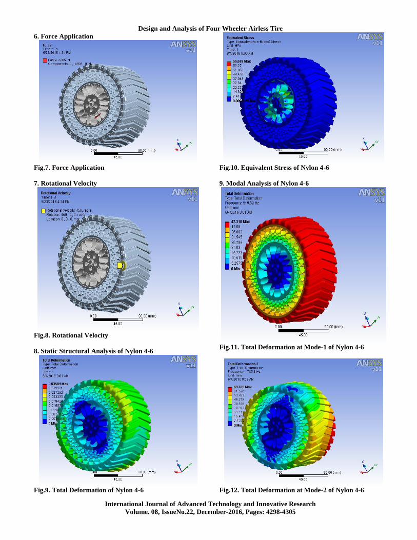
6. Force Application
Fig.7. Force Application
7. Rotational Velocity
Fig.8. Rotational Velocity
8. Static Structural Analysis of Nylon 4-6
Fig.9. Total Deformation of Nylon 4-6
Fig.10. Equivalent Stress of Nylon 4-6
9. Modal Analysis of Nylon 4-6
Fig.11. Total Deformation at Mode-1 of Nylon 4-6
Fig.12. Total Deformation at Mode-2 of Nylon 4-6
S. SHASHAVALI, C. RAGHUNATHA REDDY, GANESH KUMAR YADIKI
International Journal of Advanced Technology and Innovative Research
Volume. 08, IssueNo.22, December-2016, Pages: 4298-4305
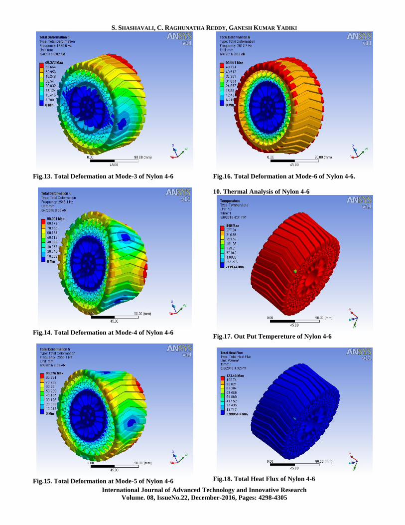
Fig.13. Total Deformation at Mode-3 of Nylon 4-6
Fig.14. Total Deformation at Mode-4 of Nylon 4-6
Fig.15. Total Deformation at Mode-5 of Nylon 4-6
Fig.16. Total Deformation at Mode-6 of Nylon 4-6.
10. Thermal Analysis of Nylon 4-6
Fig.17. Out Put Tempereture of Nylon 4-6
Fig.18. Total Heat Flux of Nylon 4-6
Design and Analysis of Four Wheeler Airless Tire
International Journal of Advanced Technology and Innovative Research
Volume. 08, IssueNo.22, December-2016, Pages: 4298-4305
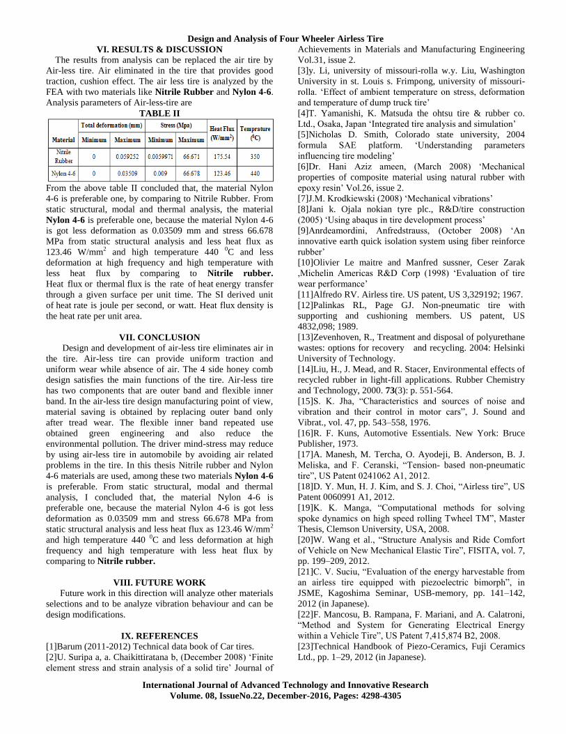
VI. RESULTS & DISCUSSION
The results from analysis can be replaced the air tire by
Air-less tire. Air eliminated in the tire that provides good
traction, cushion effect. The air less tire is analyzed by the
FEA with two materials like Nitrile Rubber and Nylon 4-6.
Analysis parameters of Air-less-tire are
TABLE II
From the above table II concluded that, the material Nylon
4-6 is preferable one, by comparing to Nitrile Rubber. From
static structural, modal and thermal analysis, the material
Nylon 4-6 is preferable one, because the material Nylon 4-6
is got less deformation as 0.03509 mm and stress 66.678
MPa from static structural analysis and less heat flux as
123.46 W/mm2 and high temperature 440
0C and less
deformation at high frequency and high temperature with
less heat flux by comparing to Nitrile rubber.
Heat flux or thermal flux is the rate of heat energy transfer
through a given surface per unit time. The SI derived unit
of heat rate is joule per second, or watt. Heat flux density is
the heat rate per unit area.
VII. CONCLUSION
Design and development of air-less tire eliminates air in
the tire. Air-less tire can provide uniform traction and
uniform wear while absence of air. The 4 side honey comb
design satisfies the main functions of the tire. Air-less tire
has two components that are outer band and flexible inner
band. In the air-less tire design manufacturing point of view,
material saving is obtained by replacing outer band only
after tread wear. The flexible inner band repeated use
obtained green engineering and also reduce the
environmental pollution. The driver mind-stress may reduce
by using air-less tire in automobile by avoiding air related
problems in the tire. In this thesis Nitrile rubber and Nylon
4-6 materials are used, among these two materials Nylon 4-6
is preferable. From static structural, modal and thermal
analysis, I concluded that, the material Nylon 4-6 is
preferable one, because the material Nylon 4-6 is got less
deformation as 0.03509 mm and stress 66.678 MPa from
static structural analysis and less heat flux as 123.46 W/mm2
and high temperature 440 0C and less deformation at high
frequency and high temperature with less heat flux by
comparing to Nitrile rubber.
VIII. FUTURE WORK
Future work in this direction will analyze other materials
selections and to be analyze vibration behaviour and can be
design modifications.
IX. REFERENCES
[1]Barum (2011-2012) Technical data book of Car tires.
[2]U. Suripa a, a. Chaikittiratana b, (December 2008) „Finite
element stress and strain analysis of a solid tire‟ Journal of
Achievements in Materials and Manufacturing Engineering
Vol.31, issue 2.
[3]y. Li, university of missouri-rolla w.y. Liu, Washington
University in st. Louis s. Frimpong, university of missouri-
rolla. „Effect of ambient temperature on stress, deformation
and temperature of dump truck tire‟
[4]T. Yamanishi, K. Matsuda the ohtsu tire & rubber co.
Ltd., Osaka, Japan „Integrated tire analysis and simulation‟
[5]Nicholas D. Smith, Colorado state university, 2004
formula SAE platform. „Understanding parameters
influencing tire modeling‟
[6]Dr. Hani Aziz ameen, (March 2008) „Mechanical
properties of composite material using natural rubber with
epoxy resin‟ Vol.26, issue 2.
[7]J.M. Krodkiewski (2008) „Mechanical vibrations‟
[8]Jani k. Ojala nokian tyre plc., R&D/tire construction
(2005) „Using abaqus in tire development process‟
[9]Anrdeamordini, Anfredstrauss, (October 2008) „An
innovative earth quick isolation system using fiber reinforce
rubber‟
[10]Olivier Le maitre and Manfred sussner, Ceser Zarak
,Michelin Americas R&D Corp (1998) „Evaluation of tire
wear performance‟
[11]Alfredo RV. Airless tire. US patent, US 3,329192; 1967.
[12]Palinkas RL, Page GJ. Non-pneumatic tire with
supporting and cushioning members. US patent, US
4832,098; 1989.
[13]Zevenhoven, R., Treatment and disposal of polyurethane
wastes: options for recovery and recycling. 2004: Helsinki
University of Technology.
[14]Liu, H., J. Mead, and R. Stacer, Environmental effects of
recycled rubber in light-fill applications. Rubber Chemistry
and Technology, 2000. 73(3): p. 551-564.
[15]S. K. Jha, “Characteristics and sources of noise and
vibration and their control in motor cars”, J. Sound and
Vibrat., vol. 47, pp. 543–558, 1976.
[16]R. F. Kuns, Automotive Essentials. New York: Bruce
Publisher, 1973.
[17]A. Manesh, M. Tercha, O. Ayodeji, B. Anderson, B. J.
Meliska, and F. Ceranski, “Tension- based non-pneumatic
tire”, US Patent 0241062 A1, 2012.
[18]D. Y. Mun, H. J. Kim, and S. J. Choi, “Airless tire”, US
Patent 0060991 A1, 2012.
[19]K. K. Manga, “Computational methods for solving
spoke dynamics on high speed rolling Twheel TM”, Master
Thesis, Clemson University, USA, 2008.
[20]W. Wang et al., “Structure Analysis and Ride Comfort
of Vehicle on New Mechanical Elastic Tire”, FISITA, vol. 7,
pp. 199–209, 2012.
[21]C. V. Suciu, “Evaluation of the energy harvestable from
an airless tire equipped with piezoelectric bimorph”, in
JSME, Kagoshima Seminar, USB-memory, pp. 141–142,
2012 (in Japanese).
[22]F. Mancosu, B. Rampana, F. Mariani, and A. Calatroni,
“Method and System for Generating Electrical Energy
within a Vehicle Tire”, US Patent 7,415,874 B2, 2008.
[23]Technical Handbook of Piezo-Ceramics, Fuji Ceramics
Ltd., pp. 1–29, 2012 (in Japanese).
S. SHASHAVALI, C. RAGHUNATHA REDDY, GANESH KUMAR YADIKI
International Journal of Advanced Technology and Innovative Research
Volume. 08, IssueNo.22, December-2016, Pages: 4298-4305
[24]Masters IG and Evans KE, “Models for the elastic
deformation of honeycombs”, Compos Struct, Vol. 35, 1996,
pp. 403–22.
[25]Tonuk E and Unlusoy YS, “Prediction of automobile tire
cornering force characteristics by finite element modeling
and analysis”, Comput Struct, Vol. 79, 2001, pp. 1219–32.
[26]Balawi S and Abot JL., “A refined model for the
effective in-plane elastic moduli of hexagonal honeycombs”,
Compos Struct, Vol. 84, 2008, pp. 25-42.
[27]Gonella S and Ruzzene M, “Homogenization and
equivalent in-plane properties of two dimensional periodic
lattices”, Int J Solid Struct, Vol. 45, 2008, pp. 2897–915.
[28]Jaehyung Ju and Joshua D. Summers, “Design of
Honeycombs for Modulus and Yield Strain in Shear”,
Journal of Engineering Materials and Technology, Vol. 134,
2012, pp. 110-126.
[29]Bekker M.G. The development of a Moon rover. Journal
of the British Interplanetary Society, 38: 537–543; 1985.
[30]Gordon J, Kauzlarich JJ, Thacker JG . Tests of two new
polyurethane foam wheelchair tires. J Rehabil Res Dev.
1989;26(1):33–46. [PMID: 2918486]