design and analysis of modified carburettor … · understanding of the flow in complex venturi....
TRANSCRIPT

International Journal of Advances in Engineering Research http://www.ijaer.com
(IJAER) 2015, Vol. No. 10, Issue No. V, November e-ISSN: 2231-5152/ p-ISSN: 2454-1796
81
INTERNATIONAL JOURNAL OF ADVANCES IN ENGINEERING RESEARCH
DESIGN AND ANALYSIS OF MODIFIED
CARBURETTOR USING CFD
*S.Palanisamy, *S.Ramanathan, **R. Naveenkumar
*Assistant Professor, Department of Mechanical Engineering, CARE Group of Institutions,
Trichy, Tamilnadu, India
**Senior Lecturer, Department of Mechanical Engineering, CARE Group of Institutions,
Trichy, Tamilnadu, India.
ABSTRACT
In this paper, nozzle and throttle plate was modeled and analyzed in order to have better
understanding of the flow in complex venturi. The carburettor body has been remodeled with two
throttle bodies replacing conventional throttle. Analysis have been performed to study flow field with
modified design. Further a comprehensive comparative study was made with the existing and
modified design. A commercial computational fluid dynamics package were used to develop a three
dimensional, fully turbulent model of the compressible flow across a complex geometry venturi, such
as those found in low speed engine carburettors. The results of CFD simulation were utilized to
understand the effect of different obstacles in flow on the mass flow rate and static pressure at the tip
of fuel Jet. The results indicated that the efficiency of the engine has been increased by the modified
carburettor.
Keywords: CFD, Carburettor and Throttle.
1. INTRODUCTION
1.1. GENERAL
Carburettors are mechanical devices that are used in gasoline / petrol engines in order to
deliver the air-fuel mixture in the right proportion to the engine under all running conditions.
This process is called carburetion. The carburettor achieves this by means of a complex set of
passages and the flow varies from laminar to fully turbulent, two-phase flow, pulsating flow
etc due to rapid changes in the operating conditions and changes in pressure and temperature.
1.2 LITERARURE REVIEW
Studies have been conducted to predict fuel flow versus air flow for a carburettor with an air
bleed system. The effects of different carburettor parts on fuel flow and air-fuel ratio can be
seen in this kind of studies. In this the main fuel orifice is the part responsible for the main
trend of the air fuel ratio under moderate-to-high air flow; the idle system is responsible for
fuel delivery under low air flow; and the air bleed system is responsible for increasing fuel
flow during the transition between the idle system and the main fuel system. All of these
studies had as a limitation the computational capabilities at the time they were performed. A

International Journal of Advances in Engineering Research http://www.ijaer.com
(IJAER) 2015, Vol. No. 10, Issue No. V, November e-ISSN: 2231-5152/ p-ISSN: 2454-1796
82
INTERNATIONAL JOURNAL OF ADVANCES IN ENGINEERING RESEARCH
significant effort was required in order to solve the nonlinear system of equations that
represented the flow network. For example, in references [3] and [4], Furuyama developed
the equations for a carburettor with idle and main circuits, and by mathematical substitution
simplified the theoretical model until a single equation was obtained. This strategy results in
a loss of information about intermediate variables, like static pressure at network nodes and
flows across secondary passages. Harrington [8] used the steady flow assumption to predict
the fuel flow for a two-barrel carburettor used in an eight-cylinder engine. The results agreed
well with experiments. Having a large number of cylinders, the assumption of steady air flow
seemed to be reasonable.
In single- and two-cylinder engines, the airflow at the venturi is expected to be
pulsating, and the application of a steady state model is expected to be limited. However,
D.K.Jagdish [6] used a steady flow assumption for a single-cylinder engine and claimed
good agreement. Sendyka’s results [9, 10] showed that instantaneous and integrated air-fuel
ratios that were leaner than those seen in real engines. It was thought that the difference
between the model and experiments was caused by the inability to capture dynamic effects of
the fuel flow.
Experimental studies performed by Furuyama and Ohgane [11] and Moss [12]
showed that the pulsating nature of the air flow affects the amount of fuel delivered by the
carburettor.
Furuyama found that the effect of pulsating air flow on fuel flow may be classified as:
i) when the throttle plate opening is large and air flow is low, the fuel flow is higher at
pulsating flow than at steady flow, and ii) when the throttle plate opening is large and air flow
is high, the fuel flow is lower at pulsating flow than at steady flow. Moss’ experiments [12]
agreed with the conclusions for the first case. Both researchers proposed that the fuel flow
under dynamic air flow may be calculated by using the steady state prediction, and then
corrected with a pulsation-correction factor. Two special considerations must be taken when
predicting the fuel flow from the carburettor circuits: the characterization of the two-phase
flow inside the emulsion tube and the characterization of the small metering orifices.
The only known work that has used CFD for the characterization of the flow across
the carburettor was done by Wu, Feng and Liu [13]. But in their work, the carburettor was
represented as a two-dimensional channel where the fuel tube was a large obstacle in the flow
field. The only results shown in this work are the static pressure drop along the axis of the
carburettor.

International Journal of Advances in Engineering Research http://www.ijaer.com
(IJAER) 2015, Vol. No. 10, Issue No. V, November e-ISSN: 2231-5152/ p-ISSN: 2454-1796
83
INTERNATIONAL JOURNAL OF ADVANCES IN ENGINEERING RESEARCH
2. DEFINITION OF PROBLEM AND OBJECTIVE
A real carburettor venturi has details in its geometry that create disturbances in the flow,
and may cause pressure losses that cause deviations from an ideal isentropic flow. Examples
of these carburettor parts are the choke plate, the throttle plate, the fuel tube, side passages to
secondary systems and, sometimes, an additional concentric fuel tube in the venturi throat.
The pressure losses created by these elements reduce the mass flow rate that could be
driven through the venturi for a given pressure difference between the inlet of the venturi and
the intake manifold.
More over increase in volumetric efficiency is essential since engines with higher
volumetric efficiency will generally be able to run at higher speeds and produce more overall
power due to less parasitic power loss moving air in and out of the engine.
In the present study, the fuel tube and the throttle plate were modeled with CFX, in
order to gain a better understanding of the characteristics of the flow, and how it is affected
by these parts.
Large volumes of small engines (two wheelers) are being sold in India every year. Its
emissions comprise a significant percentage of total pollutants in India. Better understanding
of carburettor performance and modeling could lead to better fuel mixture control and lower
emissions from small engines.
The project involves flow of compressible fluid through a confined passage and process is
to be optimized on basis of flow behavior of fluid through system.
Computational Fluid Dynamics (CFD) is capable of simulating any physical flow process.
And hence it helps better understanding of the flow pattern and to study all aspects of the
details of flow field, turbulence, recirculation zones etc. Computational Fluid Dynamics is
considered to be the most effective tool for flow analysis of carburettor venturi. There is a lot
of scope to apply CFD for this problem.
The objective of the project is as follows
• To carry out three dimensional CFD analysis of carburettor venturi to understand the
effect of the various obstacles present in the flow domain like the fuel-tube, throttle plate and
to optimize the design of carburettor by carrying out geometrical changes based on results
obtained from CFD analysis of existing model.
• To perform CFD analysis by considering the following models.
a) Ideal carburettor venturi
b) Existing carburettor venturi

International Journal of Advances in Engineering Research http://www.ijaer.com
(IJAER) 2015, Vol. No. 10, Issue No. V, November e-ISSN: 2231-5152/ p-ISSN: 2454-1796
84
INTERNATIONAL JOURNAL OF ADVANCES IN ENGINEERING RESEARCH
C) Modified carburettor venturi
2.1 DIMENSIONS OF MODEL
Inlet diameter of venturi = 25 mm
Throat diameter = 12 mm
Outlet diameter of venturi = 20 mm
Throttle plate distance from throat = 25mm
Distance between inlet and throat = 37 mm
Distance between throat and outlet = 54 mm
Length of venturi = 24 mm
Length of carburettor = 91 mm
2.2 CONSIDERATIONS IN CFD
The most fundamental consideration in CFD is how one treats a continuous fluid in a
discretised fashion on a computer. One method is to discretise the spatial domain into small
cells to form a volume mesh or grid, and then apply a suitable algorithm to solve the
equations of motion (Euler equations for inviscid and Navier–Stokes equations for viscous
flow).
This is necessitated by the fact that computational methods can only be applied to finite
number of elements and not to a continuous domain as this would translate to practically
infinite nodes for computation and thus put a tremendous load on the processing hardware
and render the solution impossible.
In addition, such a mesh can be either irregular (for instance consisting of triangles in 2D,
or pyramidal solids in 3D) or regular; the distinguishing characteristic of the former is that
each cell must be stored separately in memory. Where shocks or discontinuities are present,
high resolution schemes such as Total Variation Diminishing (TVD), Flux Corrected
Transport (FCT), Essentially Non-Oscillatory (ENO), or MUSCL schemes are needed to
avoid spurious oscillations (Gibbs phenomenon) in the solution.
2.3 MESHING
Mesh generation is the process by which spatial discretization of CFD model is
accomplished. Meshing is based on tetrahedron element discretization. Surface and volume
meshes were generated in CFX- Build module by defining the type of meshing element and
mesh element size.

International Journal of Advances in Engineering Research http://www.ijaer.com
(IJAER) 2015, Vol. No. 10, Issue No. V, November e-ISSN: 2231-5152/ p-ISSN: 2454-1796
85
INTERNATIONAL JOURNAL OF ADVANCES IN ENGINEERING RESEARCH
Fig 2.1 Meshed model -90° throttle opening position
Fig 2.2 Meshed model -45° throttle opening position
Mesh element size
Element type : Tetrahedron
Maximum Edge length : 1.5 mm
Mesh Type : Volume mesh
No. of Elements : 112000
2.4 BOUNDARY CONDITIONS AND DOMAIN SPECIFICATIONS
Inlet Boundary Conditions
Temperature = 293 K
Pressure = 1 bar
Outlet Boundary Condition
Pressure = 0.9 bar
Wall boundary Conditions
Wall influence on flow : No slip
International Journal of Advances in Engineering Research http://www.ijaer.com
(IJAER) 2015, Vol. No. 10, Issue No. V, November e-ISSN: 2231-5152/ p-ISSN: 2454-1796
86
INTERNATIONAL JOURNAL OF ADVANCES IN ENGINEERING RESEARCH
Wall Roughness : Smooth wall
Heat transfer : Adiabatic
Domain Specification
Domain Type : Fluid Domain
Fluid : air
Heat transfer Model : Thermal Energy
Turbulence Model : K-Epsilon
3. RESULTS AND DISCUSSION
3.1 MODIFIED DESIGN OF THROTTLE PLATE
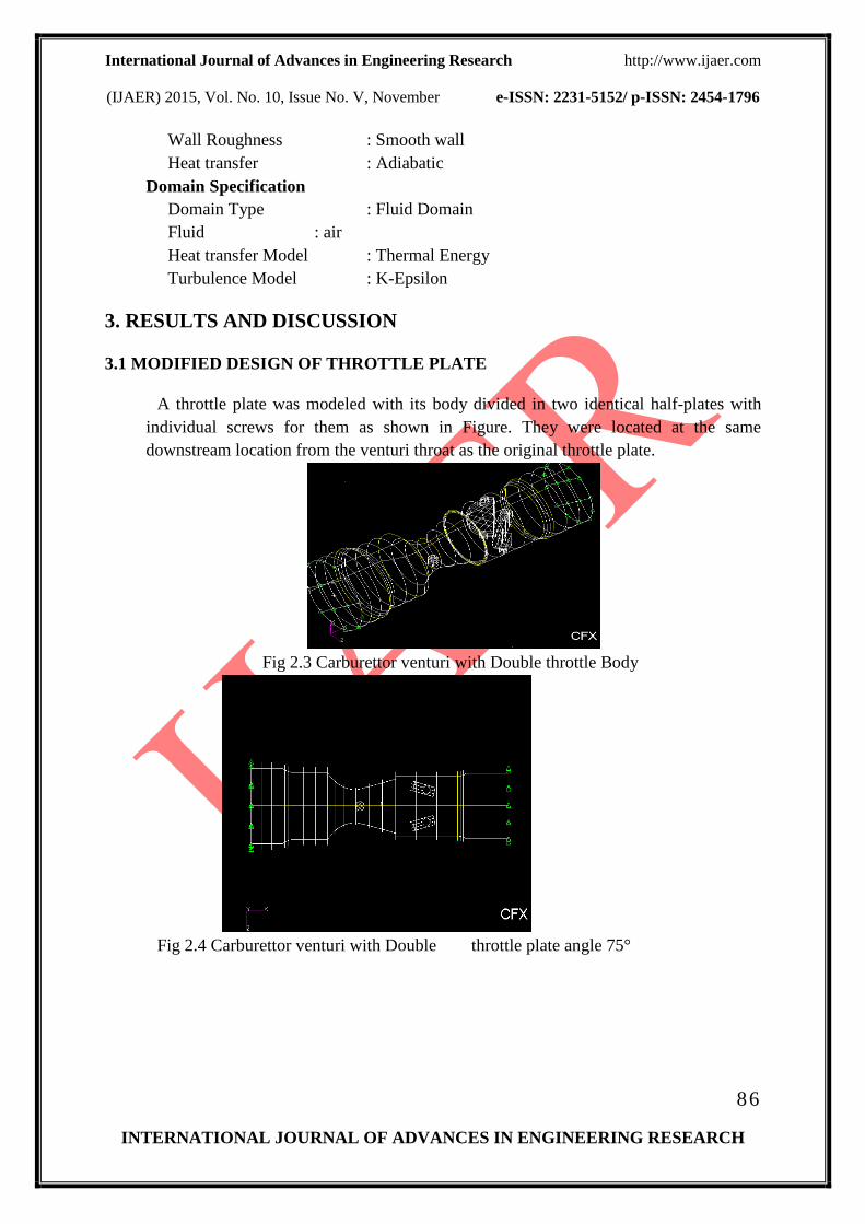
A throttle plate was modeled with its body divided in two identical half-plates with
individual screws for them as shown in Figure. They were located at the same
downstream location from the venturi throat as the original throttle plate.
Fig 2.3 Carburettor venturi with Double throttle Body
Fig 2.4 Carburettor venturi with Double throttle plate angle 75°

International Journal of Advances in Engineering Research http://www.ijaer.com
(IJAER) 2015, Vol. No. 10, Issue No. V, November e-ISSN: 2231-5152/ p-ISSN: 2454-1796
87
INTERNATIONAL JOURNAL OF ADVANCES IN ENGINEERING RESEARCH
3.2 Carburettor venturi with double throttle at 75 degrees
Fig 3.1 Total Pressure
Fig 3.2 Total Pressure
Fig 3.3 Turbulence Kinetic energy

International Journal of Advances in Engineering Research http://www.ijaer.com
(IJAER) 2015, Vol. No. 10, Issue No. V, November e-ISSN: 2231-5152/ p-ISSN: 2454-1796
88
INTERNATIONAL JOURNAL OF ADVANCES IN ENGINEERING RESEARCH
Fig 3.4 Turbulence Kinetic energy
Fig 3.5 Velocity Vectors
Fig 3.6 Velocity Vectors

International Journal of Advances in Engineering Research http://www.ijaer.com
(IJAER) 2015, Vol. No. 10, Issue No. V, November e-ISSN: 2231-5152/ p-ISSN: 2454-1796
89
INTERNATIONAL JOURNAL OF ADVANCES IN ENGINEERING RESEARCH
The models were analyzed for the same boundary conditions. The analyses of results for
75 degrees show that reduced stagnation pressure loss at downstream. The kinetic energy
field shows that it is almost constant throughout the flow. The velocity vectors clearly show
that reduced flow recirculation at downstream
3.3 STUDY OF MASS-FLOW RATE
Mass-flow rate is simply the mass of a substance that flows through a surface per unit
time. In this project, the mass-flow rate of air was recorded for all the nine carburettor
configurations using the ANSYS CFX function definition tool.
Compared to the mass-flow rate through the venturi with no obstacles, the introduction of the
fuel tube reduces the mass flow rate by 69.7 % in the case of the 3mm fuel tube and by 56.2
% in the case of the 6mm fuel tube. This shows that the 6mm fuel tube has a more
pronounced deleterious effect than the 3mm fuel tube.
The introduction of the throttle plate causes a further dip in the mass-flow rate of air.
The percentage reductions have been shown in the graph below. An interesting trend that is
observed in this study is that comparatively, the split throttle plate configurations show a
relative increase in the mass flow rate for the same angular position. This means that, for the
same available area for air flow, the split throttle plates allow more air to flow through the
carburettor. This can be attributed to the symmetrical flow and the reduction in the
undesirable eddy flow formations effected by the new designs.

International Journal of Advances in Engineering Research http://www.ijaer.com
(IJAER) 2015, Vol. No. 10, Issue No. V, November e-ISSN: 2231-5152/ p-ISSN: 2454-1796
90
INTERNATIONAL JOURNAL OF ADVANCES IN ENGINEERING RESEARCH
100
69.7
56.2
49.8
58.2361.44
67.06
59.03
65.46
0
10
20
30
40
50
60
70
80
90
100
Pla
in v
en
turi
3m
m F
ue
l tu
be
6m
m F
ue
l tu
be
3m
m F
T +
TP
45
3m
m F
T +
TP
60
3m
m F
T +
TP
75
3m
m F
T +
TP
90
3m
m F
T +
STP
60
3m
m F
T +
STP
75
Fig 3.7 Relative percentages of mass-flow rate
From the graph, it can be seen that in terms of mass flow rate the split throttle plate design
offers the following theoretical advantages quantitatively:
At 60 degrees, the proposed design offers a marginal increase of 0.8 %.
At 75 degrees, the proposed design offers an increase of 4.02 %.
Thus, it proves that the proposed design offers a marginal advantage at low speeds and a
much more substantial advantage at higher speeds.
This is a favourable observation as the mass flow rate is directly proportional to the
volumetric efficiency of an engine. An increase in the mass flow rate would have a similar
incremental effect in the performance of the engine.

International Journal of Advances in Engineering Research http://www.ijaer.com
(IJAER) 2015, Vol. No. 10, Issue No. V, November e-ISSN: 2231-5152/ p-ISSN: 2454-1796
91
INTERNATIONAL JOURNAL OF ADVANCES IN ENGINEERING RESEARCH
3.4 RESULTS OF QUANTITATIVE ANALYSIS
Table 3.1 Quantitative Analysis
3.4 VOLUMETRIC EFFICIENCY
The volumetric efficiency for the various throttle opening positions has been calculated by
using the following relation
ma = ΔP VD ήvol N /R T
where,
ma – mass flow rate in kg/sec
ΔP– Change in pressure in N/m2
VD – Displacement Volume in m3
N – Engine Speed in rpm
ήvol – Volumetric efficiency
R – Gas Constant J/kg K
T – Inlet Temperature in K
Description
Pressure
drop at
throat
%
Kinetic energy
drop at throat
%
Single
Throttle
45deg
77.49 33.17
Single
Throttle
60deg
79.7 41.54
Single
Throttle
75deg
81.18 47.02
Single
Throttle
90deg
80.38 43.958
Doublethrottle
60 80.23 43.318
Doublethrottle
75 82.61 51.652

International Journal of Advances in Engineering Research http://www.ijaer.com
(IJAER) 2015, Vol. No. 10, Issue No. V, November e-ISSN: 2231-5152/ p-ISSN: 2454-1796
92
INTERNATIONAL JOURNAL OF ADVANCES IN ENGINEERING RESEARCH
Engine Specification
Make : TVS XL Super
Type : 2 Stroke
Displacement : 69.9 CC
Max. Power : 2.61 KW – 7000 rpm
Max. Torque : 5 N-m
Bore Diameter : 46 mm
Stroke Length : 42 mm
VD = π /4* D2*L
= π /4 *( 46 x 10-3
)2*42 x 10
-3
= 6.979 X 10
-5 m
3
Calculation of volumetric Efficiency -Throttle Angle 75°
ma = ΔP VD ήvol N /R T
ma = 0.01534 kg/sec
T = 292.35 K
ΔP = (0.99773 – 0.94398) x 105
ΔP = 5339 N/m2
0.01534 = 5339 * 6.979 X 10-5
* ήvol* 7000 /287*292.35
ήvol = 0.4935 = 49.35%
S.No Description Volumetric efficiency
1 Ideal carburettor venturi 95.63%
2 Throttle angle 60 deg 45.61%
3 Throttle angle 75 deg 49.35%
4 Throttle angle 90 deg 46.03%
5 Double Throttle angle 60
deg
47.39%
6 Double Throttle angle 75
deg
53.96%
Table 3.2 Volumetric efficiency

International Journal of Advances in Engineering Research http://www.ijaer.com
(IJAER) 2015, Vol. No. 10, Issue No. V, November e-ISSN: 2231-5152/ p-ISSN: 2454-1796
93
INTERNATIONAL JOURNAL OF ADVANCES IN ENGINEERING RESEARCH
CONCLUSION
CFD analysis was done using commercial CFD solver CFX to analyze the flow
behavior of the existing carburettor body used in small engines.
The result of conventional throttle positions indicates that flow recirculation at
downstream which causes pressure fluctuations and increased stagnation pressure loss which
is undesirable. More over the velocity vectors for various throttle plate positions also show
that the recirculation in the flow just before throttle plate.
The modified model also shows comparatively increased volumetric efficiency. The
analyses of the modified model showed that the design achieves more symmetric and
organized flow at the downstream of carburettor. This simple design change has the potential
for improving mixture distribution downstream of the carburettor without major changes in
the carburettor design
REFERENCES
[1] Y. Asano, T. Chuma, H. Haga, and T. Mochida, Effects of air-bleed systems on
carburettor performance. Bulletin of JSME, pages 691–698, 1988.
[2] M. Ehara, Y. Kinabara, K. Shinoda, T. Meguro, and T. Ishihara, A study of
carburettor design. SAE technical report, 1990.
[3] M. Furuyama, Fuel supply characteristics of idle-system of carburettor under steady
state conditions. Bulletin of JSME, pages 722–729, 1988.
[4] M. Furuyama, Fuel supply characteristics in the transition region of fixed-venturi type
carburettor. Bulletin of JSME, pages 842–848, 1991.
[5] I. Isobe and Y. Asano. Discharge beginning points of fuel and bleed-air of carburettor
The University of Chiba Report, pages 173–178, 1998
[6] D. K. Jagdish, S. Govindarajan, V. Balasubramaniam, and V. Ganesan, Theoretical
and experimental investigation of metering characteristics of a variable venturi
mechanically controlled carburettor. SAE technical report, 2001.
[7] B. Sendyka and J. Filipczyk, Simulation of the characteristic of a carburettor of an
internal combustion engine. SAE technical report, 1995.

International Journal of Advances in Engineering Research http://www.ijaer.com
(IJAER) 2015, Vol. No. 10, Issue No. V, November e-ISSN: 2231-5152/ p-ISSN: 2454-1796
94
INTERNATIONAL JOURNAL OF ADVANCES IN ENGINEERING RESEARCH
[8] D. L. Harrington and J. A. Bolt, Analysis and digital simulation of carburettor
metering SAE technical report, 1990.
[9] B. Sendyka and J. Filipczyk, Simulation of the characteristic of a carburettor of an
internal combustion engine. SAE technical report, 1995.
[10] B. Sendyka and W. Heydel, The analysis of a constant depression carburettor
with a fuel feeder. SAE technical report, 1994.
[11] M. Furuyama and H. Ohgane, A comparison of pulsating and steady flows in
terms of carburettor characteristics. JSAE Review, pages 18–23, 1987.
[12] P. J. Moss. Pulsation enrichment in carburettors. Automotive Engineer, pages 53–
56, 1980.
[13] B. Wu, Y. Feng, and J. Liu, Numerical simulation of gas-liquid two-phase flow in
motorcycle carburettor. In Proceedings of the International Symposium on Multiphase
Flow, pages 271–275, 1997.
[14] Diego Arias, Timothy A. Shedd CFD analysis of compressible flow across
complex geometry venturi – Journal of Fluids Engineering – Vol.129 pages1193-1202,
2007