design and analysis of two wheeler connecting …...keywords— static structural and fatigue...
TRANSCRIPT

DOI:10.23883/IJRTER.2018.4233.GKMMY 246
DESIGN AND ANALYSIS OF TWO WHEELER CONNECTING
ROD USING 3 DIFFERENT MATERIALS
Gangadhar R.Patil1, Prof. A.C.Mattikalli2 1M.Tech. Mechanical Engg. Dept, MMEC, Belagavi
2Assistant Prof. Mechanical Engg. Dept, MMEC, Belagavi
Abstract— The main objective of this project is to determine the total deformation, stress, stiffness
and fatigue life of three different material connecting rods like structural steel [A-36], aluminium
alloy [T6-6061] and grey cast iron [HT-250] and comparison also made on these three connecting
rods under above-mentioned aspects for selection in 155cc Suzuki Gixxer SF motorcycle. In this
project, we are designed new three connecting rods using theoretical design calculations and 3D
modelling is carried out using CAD software like Unigraphics NX8.5 and simulation is carried out
using FEA software, like Ansys Workbench V15. In this simulation software we are performing Static
structural and Fatigue analysis for all three connecting rods. The boundary condition is also applied on
the basis of its working principle. Thus connecting rods are subjected to different loading conditions
due change in the mass as per design calculation. After completion of analysis process, All results
were checked under above-mentioned aspects and confirm that these connecting rods are within the
safest region or not. We have to achieve cost optimization of different materials as well as the
reduction in the manufacturing cycle time.
Keywords— Static structural and Fatigue analysis; Ansys Workbench V15; Unigraphics NX8.5; Cost
optimization; Connecting rod;
I. INTRODUCTION The main function of connecting rod is to convert reciprocating motion of the piston into rotary
motion of the crank as well as responsible for transfer power from the piston to the crankshaft and
distribution to the transmission. It is extremely strong, rigid and as light as possible, it consists of
piston pin-end, shank section and crank end. The cross-section of the shank may be rectangular,
circular, tubular, I-section or H-section. Generally circular section is used for low speed engines,
while I-section is used for high speed engines. The material for a connecting rod is selected depending
upon the requirement of the I.C engines. These connecting rods are usually made of steel for
production engines, but can be made of aluminium [for weightlessness and the capacity to take up
high crash at the cost of durability] or titanium [for a mixture of strength and weightlessness at the
expenditure of affordability] for elevated performance engines, or of cast iron for applications such as
motor scooters. Connecting rod materials must have good fatigue and shock resistances.
Durability is one of the critical importance of this component; this can be achieved by getting the
knowledge about different aspects such as production technology, materials, performance simulation,
and fatigue. When building a high performance engine, great attention is paid to the connecting rods,
eliminating stress risers by such techniques as grinding the edges of the rod to a smooth radius, shot
peening to induce compressive surface stresses (to prevent crack initiation). Time and effort were
necessary to create the best design for a connecting rod to allow it to handle high stresses while
minimizing weight. The reduction of weight of connecting rods is important to ensure that the engine
can operate safely in higher RPM’s due to the decreased inertia held within the lighter rods. The goal
has become to remove as much material from these rods while still maintaining their strength and
integrity so as to safely perform under the conditions of each engine.
International Journal of Recent Trends in Engineering & Research (IJRTER) Volume 04, Issue 04; April - 2018[ISSN: 2455-1457]
@IJRTER-2018, All Rights Reserved 247
II. OBJECTIVE
Selection of suitable connecting rod for 155cc Suzuki Gixxer SF motorcycle. Design of
connecting rods using theoretical design calculations and geometric modelling is carried out in
Unigraphics NX8.5 and simulation is carried out in Ansys WorkbenchV15 software. Perform Static
structural and Fatigue analysis for all three connecting rods. Check for all results under aspects like
total deformation, stress, stiffness and fatigue life and Finally confirm that these connecting rods are
within the safest region or not. Also check for cost optimization of different materials as well as
reduction in the manufacturing cycle time.
III. MATERIAL SELECTION
In this project, there are totally 3 different materials taken into account for the production of
connecting rod.
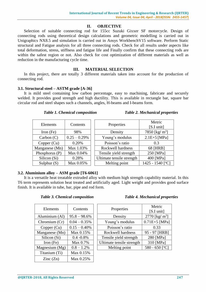
3.1. Structural steel – ASTM grade [A-36]
It is mild steel containing low carbon percentage, easy to machining, fabricate and securely
welded. It provides good strength and high ductility. This is available in rectangle bar, square bar
circular rod and steel shapes such a channels, angles, H-beams and I-beams form.
Table 1. Chemical composition Table 2. Mechanical properties
Elements Contents
Properties Metric
[S.I unit]
Iron (Fe) 98% Density 7850 [kg/ m3]
Carbon (C) 0.25 – 0.29% Young’s modulus 2.1E+5 [MPa]
Copper (Cu) 0.20% Poisson’s ratio 0.3
Manganese (Mn) Max 1.03% Rockwell hardness 68 [HRB]
Phosphorus (P) Max 0.04% Tensile yield strength 250 [MPa]
Silicon (Si) 0.28% Ultimate tensile strength 400 [MPa]
Sulphur (S) Max 0.05% Melting point 1425 - 1540 [oC]
3.2. Aluminium alloy – ASM grade [T6-6061] It is a versatile heat treatable extruded alloy with medium high strength capability material. In this
T6 term represents solution heat treated and artificially aged. Light weight and provides good surface
finish. It is available in tube, bar, pipe and rod form.
Table 3. Chemical composition Table 4. Mechanical properties
Elements Contents
Properties Metric
[S.I unit]
Aluminium (Al) 95.8 – 98.6% Density 2770 [kg/ m3]
Chromium (Cr) 0.04 – 0.35% Young’s modulus 0.71E+5 [MPa]
Copper (Cu) 0.15 – 0.40% Poisson’s ratio 0.33
Manganese (Mn) Max 0.15% Rockwell hardness 95 - 97 [HRB]
Silicon (Si) 0.4 -0.8% Tensile yield strength 280 [MPa]
Iron (Fe) Max 0.7% Ultimate tensile strength 310 [MPa]
Magnesium (Mg) 0.8 – 1.2% Melting point 580 - 650 [oC]
Titanium (Ti) Max 0.15%
Zinc (Zn) Max 0.25%

International Journal of Recent Trends in Engineering & Research (IJRTER) Volume 04, Issue 04; April - 2018[ISSN: 2455-1457]
@IJRTER-2018, All Rights Reserved 248
3.3. Grey cast iron – grade [HT-250]
It is a type of cast iron, having graphitic microstructure with low cost and good machinability,
which result from the graphite lubricating the cut and breaking up the chips. Having good damping
capacity to absorbs the energy and converts it into heat.
Table 5. Chemical composition Table 6. Mechanical properties
Elements Contents
Properties Metric
[S.I unit]
Iron (Fe) 89% Density 7200 [kg/ m3]
Carbon (C) 3 – 3.3% Young’s modulus 1.26E+5 [MPa]
Graphite (Gr) 6 – 10% Poisson’s ratio 0.26
Silicon (Si) 1.4 – 1.7% Brinell hardness 190 [HBS]
Manganese (Mn) 0.8 – 1% Ultimate tensile strength 240 [MPa]
Phosphorus (P) 0.15% Ultimate compressive strength 820 [MPa]
Sulphur (S) 0.12% Melting point 1200 – 1400 [oC]
IV. THEORETICAL DESGIN CALCULATION OF CONNECTING ROD
4.1. Configuration of Suzuki gixxer SF model
Considering 155cc engine,
Engine type - Air cooled, 4-stroke, having
Bore, B or Piston diameter, D = 56 mm
Stroke, S = 62.9 mm
Number of Cylinders, n = 1
Displacement = 154.9 cm3 i.e. [π/4*B2*S*n]
Length of connecting rod, L = 2 * stroke of piston= 2 * 62.9 = 125.8mm
Maximum Power, P = 14.8 bhp at 8000 RPM
Maximum Torque, T = 14 N-m at 6000 RPM
4.2. Specification of Petrol
Compression Ratio of PETROL [C8H18] = 9.35:1
Density of petrol, ρ = 737.22E-9 kg / mm3
Molecular weight, M = 114.228 g / mole
Ideal gas constant, R = 8.314 J / mol-K
Temperature, T = 27oC+273 = 300 Kelvin (K) [ Ideal room temperature]
From perfect gas equation,
PV = mRspecific T
P = Pressure, V= Volume, m = Mass, T = Ideal room temperature and Rspecific = Specific gas constant
Mass, m = Density * Volume
= 737.22E-9 * 154.9E3
= 0.1142 kg * 9.81= 1.12 N.
Rspecific = R / M
= 8.314 / 0.11422 = 72.79 J / kg.K
Substitute all above values in perfect gas equation, we get
Pressure (P) = 16 MPa or 160 Bar.
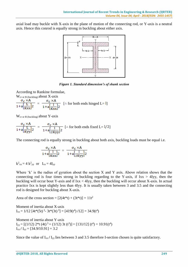
4.3. Standard dimension’s of shank ‘I’ section
A connecting rod is a machine member which is subjected to alternating tensile and compressive
forces. Thus compressive forces are higher than the tensile forces, thus the cross section of the
connecting rod is designed as a strut and rankine formulae is used. A connecting rod is subjected to an
International Journal of Recent Trends in Engineering & Research (IJRTER) Volume 04, Issue 04; April - 2018[ISSN: 2455-1457]
@IJRTER-2018, All Rights Reserved 249
axial load may buckle with X-axis in the plane of motion of the connecting rod, or Y-axis is a neutral
axis. Hence this conrod is equally strong in buckling about either axis.
Figure 1. Standard dimension’s of shank section
According to Rankine formulae,
Wcr or B (buckling) about X-axis
= [ for both ends hinged L= ]
Wcr or B (buckling) about Y-axis
= [ for both ends fixed L= ]
The connecting rod is equally strong in buckling about both axis, buckling loads must be equal i.e.
=
k2xx = 4 k2
yy or Ixx = 4Iyy
Where ‘k’ is the radius of gyration about the section X and Y axis. Above relation shows that the
connecting rod is four times strong in buckling regarding to the Y-axis, if Ixx > 4Iyy, then the
buckling will occur bout Y-axis and if Ixx < 4Iyy, then the buckling will occur about X-axis. In actual
practice Ixx is kept slightly less than 4Iyy. It is usually taken between 3 and 3.5 and the connecting
rod is designed for buckling about X-axis.
Area of the cross section = [2(4t*t) + (3t*t)] = 11t2
Moment of inertia about X-axis
Ixx = 1/12 [4t*(5t) 3- 3t*(3t) 3] = [419(t4) /12] = 34.9(t4)
Moment of inertia about Y-axis
Iyy = [(1/12) 2*t (4t) 3 + (1/12) 3t (t3)] = [131/12] (t4) = 10.91(t4)
Ixx / Iyy = [34.9/10.91] = 3.2
Since the value of Ixx / Iyy lies between 3 and 3.5 therefore I-section chosen is quite satisfactory.
International Journal of Recent Trends in Engineering & Research (IJRTER) Volume 04, Issue 04; April - 2018[ISSN: 2455-1457]
@IJRTER-2018, All Rights Reserved 250
From standards, all dimensions are in [mm]
Thickness of flange and web of the thickness = [t]
Width of the section B = 4[t]
Height of the section H = 5[t]
Area of section A = 11[t2]
Moment of inertia about X –axis, Ixx = 34.9[t4]
Moment of inertia about Y-axis, Iyy = 10.91[t4]
Radius of gyration about X-axis, kxx = 1.78[t]
Height at the big end, H1 = [1.1H to 1.125H]
Height at the small end, H2 = [0.75H to 0.9H]
4.4. Static forces acting on the connecting rod
The stresses in the connecting rod are set up due to following forces acting on it.
Force on the piston due to gas pressure and Inertia of reciprocating parts.
Force due to inertia of connecting rod or inertia of bending forces.
Force due to Friction of piston rings and the piston.
Force due to friction of the piston pin bearing and the crank pin bearing.
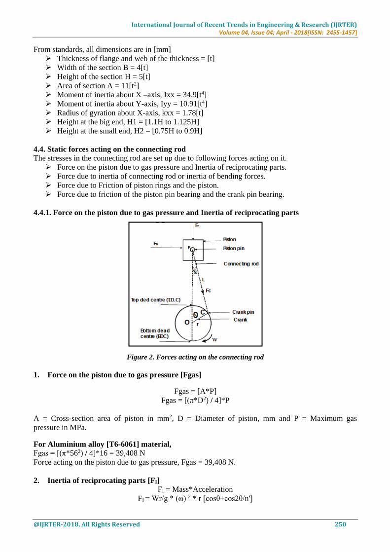
4.4.1. Force on the piston due to gas pressure and Inertia of reciprocating parts
Figure 2. Forces acting on the connecting rod
1. Force on the piston due to gas pressure [Fgas]
Fgas = [A*P]
Fgas = [(π*D2) / 4]*P
A = Cross-section area of piston in mm2, D = Diameter of piston, mm and P = Maximum gas
pressure in MPa.
For Aluminium alloy [T6-6061] material,
Fgas = [(π*562) / 4]*16 = 39,408 N
Force acting on the piston due to gas pressure, Fgas = 39,408 N.
2. Inertia of reciprocating parts [FI]
FI = Mass*Acceleration
FI = Wr/g * (ω) 2 * r [cosθ+cos2θ/n']

International Journal of Recent Trends in Engineering & Research (IJRTER) Volume 04, Issue 04; April - 2018[ISSN: 2455-1457]
@IJRTER-2018, All Rights Reserved 251
Wr = Mass of reciprocating parts, N
ω = Angular speed of crank, rad/sec
r = Crank radius, mm = [Stroke of the piston/2]
θ = Angle between the crank and the center line of the cylinder or angle of inclination of crank from
Top Dead Centre (i.e. 0 to 360o at TDC and 180oat BDC), deg
Cosθ = cosine of the crank angle and varies between 0 and ± 1throught 360o of crank rotation.
n' = l / r = ratio of connecting rod length to radius of crank
From figure 2,
Fp = force acting on the piston due to gas pressure and inertia of reciprocating parts, N
Fc = Component of Fp acting along the axis of connecting rod, N
α = Angle between the crank and the center line of connecting rod, deg
∅ = Angle between the center line of piston and the connecting rod, deg
For Aluminium alloy [T6-6061] material,
i. Mass of reciprocating parts, Wr = mass of piston + 0.33 * mass of connecting rod
Mass of connecting rod, m = Density * (Area * Length)
m = 2770 * [11 * (5.5 * 10-3)2 * 0.1258] = 0.116 kg
Assuming mass of piston = 1.11 kg.
Wr = [1.11 + (0.33 * 0.116)]
Mass of reciprocating parts, Wr = 1.15 kg * 9.81 = 11.28 N.
ii. Angular speed of crank, ω = 2πN/60
Engine speed, N = 8000 RPM
Angular speed of crank, ω = [2π x 8000 / 60] = 837.75 rad / sec.
iii. Crank radius, r = Stroke of the piston / 2
r = 62.9 / 2 = 31.45 mm.
Length of connecting rod, l = 125.8 mm.
iv. n' = l/r = 125.8/31.45 = 4
θ = 0, considering connecting rod is at top dead centre.
Substitute all values in above Equation we get,
FI = (11.28 / 9810) * (837.75)2 * 31.45 [1 + (0.25)]
Force of inertia due to reciprocating parts, FI = 31,725 N.
3. Net force acting on the piston pin [Fp]
It may be noted that the inertia force of reciprocating parts opposes the force on the piston when it
moves during downward stroke.
Fp = Force due to gas pressure ± Inertia force
Fp = Fgas - FI
After substituting the values of Fgas and FI we get,
Net force acting on the piston pin, Fp or net = 7683 N.
4. Component of Fp acting along the axis of connecting rod [FC]
Fc = Fp / [Sqrt (1-[sinθ/n']2)]
The forces in the connecting rod will be maximum, when the crank and the connecting rod are
perpendicular to each other when θ= 90o.
Component of Fp acting along the axis of connecting rod, Fc = 7935 N.
Therefore total force acting on the Aluminium alloy [T6-6061] material connecting rod is 7935 N.
The same procedure is followed for other two materials. Hence total force acting on the connecting
rod is mention in below table.
International Journal of Recent Trends in Engineering & Research (IJRTER) Volume 04, Issue 04; April - 2018[ISSN: 2455-1457]
@IJRTER-2018, All Rights Reserved 252
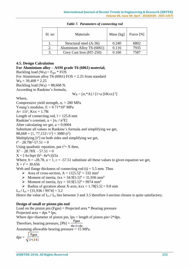
Table 7. Parameters of connecting rod
4.5. Design Calculation
For Aluminium alloy – ASM grade T6 (6061) material,
Buckling load (WB) = Fgas * FOS
For Aluminium alloy T6 (6061) FOS = 2.25 from standard
WB = 39,408 * 2.25
Buckling load (WB) = 88,668 N.
According to Rankine’s formula,
WB = [σc*A] / [1+a [l/Kxx] 2]
Where,
Compressive yield strength, σc = 280 MPa
Young’s modulus, E = 0.71*105 MPa
A= 11t2, Kxx = 1.78t
Length of connecting rod, l = 125.8 mm
Rankine’s constant, a = [σc / π2E]
After calculating we get, a = 0.0004
Substitute all values in Rankine’s formula and simplifying we get,
88,668 + [1, 77,153 / t2] = 3080 (t2)
Multiplying [t2] on both sides and simplifying we get,
t4 – 28.78t2-57.51 = 0
Using quadratic equation, put t2= X then,
X2 – 28.78X – 57.51 = 0
X = [-b±Sqrt (b2- 4a*c)]/2a
Where, b = -28.78, a = 1, c = -57.51 substitute all these values to given equation we get,
X = t2 = 30.656
Web and flange thickness of connecting rod (t) = 5.5 mm. Thus
Area of cross-section, A = 11[5.5]2 = 332 mm2
Moment of inertia, Ixx = 34.9[5.5]4 = 31,936 mm4
Moment of inertia, Iyy = 10.9[5.5]4 = 9974 mm4
Radius of gyration about X-axis, kxx = 1.78[5.5] = 9.8 mm
Ixx / Iyy = [31,936 / 9974] = 3.2
Hence the value of Ixx / Iyy lies between 3 and 3.5 therefore I-section chosen is quite satisfactory.
Design of small or piston pin end
Load on the piston pin (Fgas) = Projected area * Bearing pressure
Projected area = dps * lps,
Where dps=diameter of piston pin, lps = length of piston pin=2*dps.
Therefore, bearing pressure, [Pb] =
Assuming allowable bearing pressure = 15 MPa.
dps =
Sl. no Materials
Mass [kg]
Force [N]
1. Structural steel (A-36) 0.240 6802
2. Aluminium Alloy T6-(6061) 0.116 7935
3. Grey Cast Iron (HT-250) 0.160 7587

International Journal of Recent Trends in Engineering & Research (IJRTER) Volume 04, Issue 04; April - 2018[ISSN: 2455-1457]
@IJRTER-2018, All Rights Reserved 253
dps = 36 mm.
lps = 2 * 36 = 72 mm.
Design of inner, outer diameter and length of small end
Inner diameter of small end (dsi) = (1.1-1.25) dps
dsi = 1.1 * 36 = 40 mm.
Outer diameter of small end (dso) = (1.25–1.65) dps
dso = 1.4 * 36 = 50 mm.
Length of small end (ls) = (0.3–0.45) D
ls = 0.45 * 56 = 25 mm.
Design of big or crank end Considering the bearing failure of the crank and assuming the empirical relation.
Diameter of crank pin (dpc) = (0.55 – 0.75) D
dpc = 0.75 * 56 = 42 mm.
Length of crank pin (lc) = 1.5 * dpc
lc = 1.5 * 42 = 63 mm
Bearing pressure (Pb) = [Fgas / dpc * lc] = [39,408 / (42 * 63)] = 15MPa.
Design of inner, outer diameter and length of big end
Inner diameter of big end (dbi) = (1.1 – 1.25) dpc
dbi = 1.25 * 42 = 52 mm.
Outer diameter of big end (dbo) = (1.25 – 1.65) dpc
dbo = 1.65 * 42 = 69 mm.
Length of big end (lb) = (0.45 – 1) dpc
lb = 0.75 * 42 = 31.5 mm.
The same procedure is followed for other two materials. Hence entire specification of the connecting
rod is mention in below table.
Table 8. Specification of connecting rod
Sl.no Parameters Aluminium
Alloy
Structural
Steel
Grey Cast
Iron
1. Thickness of flange and web of connecting rod [t] 5.5 4.7 4
2. Width of the section [B= 4t] 22 19 16
3. Height of the section [H=5t] 28 24 20
4. Height at the big end H1= [1.1H - 1.125H] 31 26 22
5. Height at the small end H2= [0.75H – 0.9H] 21 18 15
6. Inner diameter of small end 40 40 40
7. Outer diameter of small end 50 50 50
8. Length of small end 25 25 25
9. Inner diameter of big end 52 52 52
10. Outer diameter of big end 69 69 69
11. Length of big end 32 32 32
V. 3D MODEL OF CONNECTING ROD
Unigraphics NX8.5 modeling tool is used to create a complete 3D model of connecting rod.

International Journal of Recent Trends in Engineering & Research (IJRTER) Volume 04, Issue 04; April - 2018[ISSN: 2455-1457]
@IJRTER-2018, All Rights Reserved 254
Figure 3. Structural steel grade [A-36] connecting rod
Figure 4. Aluminium alloy grade [T6-6061] connecting rod
Figure 5. Grey cast iron grade [HT-250] connecting rod
VI. FEA ANALYSIS OF CONNECTING ROD
Analysis of connecting rod is done through Ansys workbench V14.5 software. Here we are
performing the Static Stress Analysis, Fatigue Analysis for all three materials i.e. Structural steel A-
36, Aluminium alloy T6-(6061) and Grey cast iron (HT-250).

International Journal of Recent Trends in Engineering & Research (IJRTER) Volume 04, Issue 04; April - 2018[ISSN: 2455-1457]
@IJRTER-2018, All Rights Reserved 255
Static structural analysis helps in determining the strength of an object or connecting rod in terms
of stress, deformation, stiffness etc.
Fatigue analysis helps in determining the Life cycle of an object or connecting rod in terms of
cycles.
6.1. Mesh generation
Figure 6. Structural steel grade [A-36] connecting rod
Figure 7. Aluminium alloy grade [T6-6061] connecting rod
Figure 8. Grey cast iron grade [HT-250] connecting rod
International Journal of Recent Trends in Engineering & Research (IJRTER) Volume 04, Issue 04; April - 2018[ISSN: 2455-1457]
@IJRTER-2018, All Rights Reserved 256
Table 9. Meshing data
Material Elements Nodes Element size Element type Mesh type
Structural steel [A-36] 7489 28983 3 Solid 186, 187 Quad mesh
Aluminium alloy T6-[6061] 6615 27046 3 Solid 186, 187 Quad mesh
Grey cast iron [HT-250] 7625 28642 3 Solid 186, 187 Quad mesh
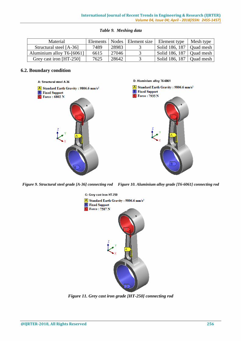
6.2. Boundary condition
Figure 9. Structural steel grade [A-36] connecting rod Figure 10. Aluminium alloy grade [T6-6061] connecting rod
Figure 11. Grey cast iron grade [HT-250] connecting rod

International Journal of Recent Trends in Engineering & Research (IJRTER) Volume 04, Issue 04; April - 2018[ISSN: 2455-1457]
@IJRTER-2018, All Rights Reserved 257
Connecting rod is subjected to compressive load or force about 6802N, 7935N and 7587N in ‘Z’-
direction on piston pin end region and all DOF [Degree of freedom] is fixed at crank end region.
6.3. Analysis result
6.3.1. Static structural analysis
Structural steel [A-36] material connecting rod
Figure 12. Deformation contour of connecting rod Figure 13. Von-Mises stress contour of connecting rod
Aluminium alloy [T6-6061] material connecting rod
Figure 14. Deformation contour of connecting rod Figure 15. Von-Mises stress contour of connecting rod
International Journal of Recent Trends in Engineering & Research (IJRTER) Volume 04, Issue 04; April - 2018[ISSN: 2455-1457]
@IJRTER-2018, All Rights Reserved 258
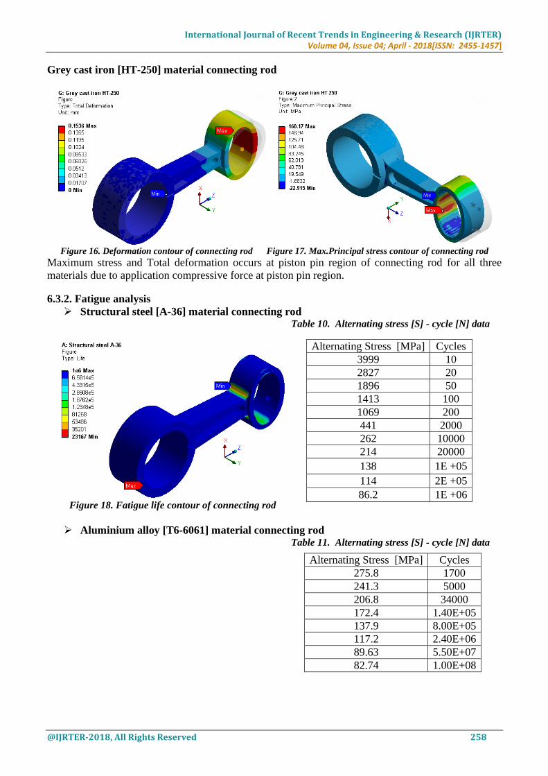
Grey cast iron [HT-250] material connecting rod
Figure 16. Deformation contour of connecting rod Figure 17. Max.Principal stress contour of connecting rod
Maximum stress and Total deformation occurs at piston pin region of connecting rod for all three
materials due to application compressive force at piston pin region.
6.3.2. Fatigue analysis
Structural steel [A-36] material connecting rod Table 10. Alternating stress [S] - cycle [N] data
Figure 18. Fatigue life contour of connecting rod
Aluminium alloy [T6-6061] material connecting rod Table 11. Alternating stress [S] - cycle [N] data
Alternating Stress [MPa] Cycles
3999 10
2827 20
1896 50
1413 100
1069 200
441 2000
262 10000
214 20000
138 1E +05
114 2E +05
86.2 1E +06
Alternating Stress [MPa] Cycles
275.8 1700
241.3 5000
206.8 34000
172.4 1.40E+05
137.9 8.00E+05
117.2 2.40E+06
89.63 5.50E+07
82.74 1.00E+08

International Journal of Recent Trends in Engineering & Research (IJRTER) Volume 04, Issue 04; April - 2018[ISSN: 2455-1457]
@IJRTER-2018, All Rights Reserved 259
Figure 19. Fatigue life contour of connecting rod
Graph 1. Constant amplitude load fully reversed [A-36] Graph 2. Constant amplitude load fully reversed [T6-6061]
Grey cast iron [HT-250] material connecting rod For this material the fatigue result is unavailable because of fatigue data for this material is missing in
material library, which is stored in ansys workbench software. Therefore fatigue result of this material
is calculated by analytical method in calculation part shown below.
VII. CALCULATION
7.1. Fatigue life calculation of grey cast iron [HT-250] material connecting rod
The Grey cast iron is one of the brittle material, hence Goodman equation is used to predict life cycle
of the connecting rod.
Goodman equation is given by,
[σalternating / σendurance limit] + [σmean / σultimate] =1
Where,
σmean = [σmax + σmin / 2]
σalternating = [σmax - σmin / 2] and
σultimate = Ultimate strength of Grey cast iron material
From ansys software we got maximum and minimum equivalent stress values on that basis calculating
life cycle for grey cast iron connecting rod.
Maximum stress, (σmax) = 168.17 MPa
Minimum stress, (σmin) = 22.915 MPa
Mean stress, (σmean) = 95.5425 MPa
Alternating stress, (σalternating) = 72.6275 MPa
Ultimate strength or stress, (σultimate) = 820 MPa

International Journal of Recent Trends in Engineering & Research (IJRTER) Volume 04, Issue 04; April - 2018[ISSN: 2455-1457]
@IJRTER-2018, All Rights Reserved 260
Substituting above given values into the Goodman equation after simplification we get,
Endurance limit stress, σendurance limit = 82.205 MPa.
Fatigue life can be calculated by following equation,
S = 10c * Nb
S = Alternating stress or Amplitude stress [MPa]
N = Number of cycles [cycles] and b, c are the slope constants.
b = -1/3 log [(0.8 * ultimate strength or stress) / (endurance limit stress)]
c = log [(0.8 * ultimate strength or stress) 2 / (endurance limit stress)]
Substituting the ultimate and endurance stress values in above b and c equation after simplification we
get b = -0.30066 and c = 3.7189.
Hence predicting the life cycles of the connecting rod for endurance stress,
S = [σendurance limit] hence,
σe = 10c * Nb or
N = 10[-c/b] * σe [1/b]
Substitute c, b and endurance stress values in above equation we get,
82.205 = 10(3.7189) * N (-0.30066)
N = 1000319.916 cycles or 10.00319E+5 cycles.
From analytical calculation, we obtain the maximum life cycle of grey cast iron [HT-250] connecting
rod is 1.000319E+6 cycles for an endurance stress of 82.205 MPa.
VIII. RESULTS
8.1. Static structural analysis
Table 12. Mechanical parameters of connecting rod
8.2. Fatigue analysis Table 13. Fatigue life of connecting rod
Sl.no Materials
Fatigue life [Cycle]
Theoretical
result
Ansys result
Maximum Minimum
1. Structural Steel (A-36) 9.99815E+5 1.0E+6 23167
2. Aluminium Alloy T6-(6061) 9.97401E+5 1.0E+8 52832
3. Grey Cast Iron (HT-250) 1.00032E+6 - -
IX. CONCLUSION
Parameters based on,
1. Mass Mass of Structural steel grade A36 material connecting rod is 0.240 kg.
Mass of Aluminium alloy grade T6-(6061) material connecting rod is 0.116 kg.
Mass of Grey cast iron grade HT- 250 material connecting rod is 0.160 kg.
Percentage reduction of mass in Aluminium alloy with respect to structural steel material
connecting rod is 51.66%.
Sl.no Materials
Mechanical Parameters
Stress
[MPa]
Deformation
[mm]
Stiffness
[N/mm]
1. Structural Steel (A-36) 205.59 0.0713 33
2. Aluminium Alloy T6 (6061) 196.09 0.2139 5.32
3. Grey Cast Iron (HT-250) 168.17 0.1536 10.21

International Journal of Recent Trends in Engineering & Research (IJRTER) Volume 04, Issue 04; April - 2018[ISSN: 2455-1457]
@IJRTER-2018, All Rights Reserved 261
Percentage reduction of mass in Grey cast iron with respect to structural steel material
connecting rod is 33.33%.
Therefore, Aluminium alloy material is selected for its light weight thus mechanical efficiency of the
engine can be improved.
2. Cost
Structural steel grade A-36 material has market price of approx. Rs.42/kg.
luminium alloy grade T6-(6061) material has market price of approx. Rs.210/kg.
Grey cast iron grade HT-250 material has market price of approx. Rs.110/kg.
Therefore, Structural steel A-36 material is selected for its low price.
3. Stress
Structural steel grade A-36 conecting rod generates stress is about 205.59 MPa.
Aluminium alloy grade T6-(6061) connecting rod generates stress is about 196.09 MPa.
Grey cast iron grade HT-250 connecting rod generates stress is about 168.17 MPa.
Percentage reduction of stress in Aluminium alloy with respect to structural steel material
connecting rod is 4.62%.
Percentage reduction of stress in Grey cast iron with respect to structural steel material
connecting rod is 18.20%.
All materials are well below the yield stregth hence all materials are safe.
Therefore, Grey cast iron material connecting rod is selected for generation of less stress.
4. Stiffness
Stiffness of Sructural steel grade A-36 material connecting rod is 33 N/mm.
Stiffness of Aluminium alloy grade T6-(6061) material connecting rod is 5.32 N/mm and
Stiffness of Grey cast iron grade HT-250 material connecting rod is 10.21 N/mm.
Percentage increase of stiffness in Structural steel with respect to Aluminium alloy material
connecting rod is 520.3%.
Percentage increase of stiffness in Structural steel with respect to Grey cast iron material
connecting rod is 223.21%.
Therefore, Structural steel material connecting rod is selected for maximum stiffness thus it has more
capacity to withstand or resist the deformation and material is act as a rigid body.
5. Fatigue life
With the prediction of high cycle fatigue life, the life of connecting rod is evaluated and
obtained a satisfactory result of 1E+6 cycles.
From result table we conclude that, Aluminium alloy material connecting rod has maximum life of
1.0E+8 cycles. Thus increasing in the durability of connecting rod.
REFERENCES I. K. Sudershan Kumar, Dr. K. Tirupathi Reddy, Syed Altaf Hussan, “Modeling and Analysis of Two Wheeler
Connecting Rod”, International Journal of Modern Engineering Research, vol-2, Issue-5, Pp-3367-3371, Sep-Oct-
2012.
II. Kuldeep B, Arun L.R, Mohammed Faheem, “Analysis and Optimization of Connecting Rod using Alfasic
Composites”, ISSN: 2319-8753 International Journal of Innovative Research in Science, Engineering and
Technology, vol. 2, Issue 6, June 2013.
III. S. Aishwarya and E.V.V. Ramanamurthy, “Design and Optimization of Connecting Rod for 4–Stroke Petrol
Engine by Using Finite Element Analysis”, ARPN Journal of Engineering and Applied Sciences, vol.10, no.11,
June 2015.
IV. Vivek.C.Pathade, Bhumeshwar Patle, Ajay N. Ingale, “Stress Analysis of I.C. Engine Connecting Rod by Fem”,
International Journal Of Engineering and Innovative Technology, vol-1, Issue-3, Pp-12-15, March2012.
V. Leela Krishna Vegi et al, (2013), “Design and Analysis of Connecting Rod using Forged Steel”, International
Journal of Scientific & Engineering Research, volume-4, Issue-6, Pp. 2081-2090.