design and analysis of wimax and wlan notched ... issn: 2347-1697 international journal of...
TRANSCRIPT
.
4974 Available Online through: http://ijifr.com/searchjournal.aspx
This work is published under Attribution-NonCommercial-ShareAlike 4.0 International License
Copyright©IJIFR 2016
International Journal of Informative & Futuristic Research ISSN: 2347-1697
Volume 4 Issue 1 September 2016 www.ijifr.com
Abstract
A dual band-notched compact ultra wideband antenna is presented, with a modified rectangular patch and truncated ground plane. To generate single and dual band-notched characteristics, we use two inverted U-shaped slots, instead of changing the patch or feedline shapes. By properly adjusting the dimensions of these elements, two controllable notch resonances are achieved. The simulated results shows that the proposed dual band-notched monopole antenna offers a very wide bandwidth from 3 to 12 GHz, defined by less than -10dB return loss, with two notched bands, covering all the 3.3 to 3.7GHz WiMAX and 5.1 to 6GHz WLAN2. Impedance, radiation and efficiency characteristics of the antenna are also discussed. The proposed antenna is simulated using CAD FEKO 6.2 suit electromagnetic simulator using MoM (Method of Moment.
I. INTRODUCTION
In recent years, design of ultra-wideband (UWB) antennas has received an increasing
attention after adoption of frequency band from 3.1 to 10.6 GHz for UWB applications by
the Federal Communication Commission in 2002. Various kind of planar broadband
antennas have been studied and reported for UWB applications [1-4]. Many of them have
large radiation patch connected with the microstrip-fed line [4-5].
Design And Analysis Of Wimax And
WLAN Notched Rectangular
Microstrip Patch UWB Antenna Paper ID IJIFR/V4/ E1/ 042 Page No. 4974-4984 Subject Area
Electronics &
Telecommunication
Keywords Patch Antenna, Ultrawideband, Radiating Patch, Defected Ground Plane,
Method Of Moment
1st Sachin S. Aher Dept. Of Electronics & Telecommunication,
MGM's Jawaharlal Nehru Engineering College,
Aurangabad-Maharashtra, India
2nd S. A. Annadate Dept. Of Electronics & Telecommunication,
MGM's Jawaharlal Nehru Engineering College,
Aurangabad-Maharashtra, India

4975
ISSN: 2347-1697
International Journal of Informative & Futuristic Research (IJIFR)
Volume - 4, Issue -1, September 2016
Continuous 37th Edition, Page No: 4974-4984
Sachin S. Aher, S. A. Annadate :: Design And Analysis Of Wimax And WLAN Notched Rectangular Microstrip Patch UWB Antenna
There are several techniques are defined to obtain the notched band characteristics
such as tuning stub technique[6], designing of different shaped slots on the microstrip
Antenna patch[7-8], design using parasitic elements of various geometries[9-10] or by
fractal geometry of an antenna[11]. Simple and commonly used approach is to incorporate
slots or parasitic strips into the antennas’ radiator, such as δ-shaped slots, U-shaped slots
[12] and I-shaped parasitic strips [13], which are known as half-wavelength or quarter-
wavelength resonator structures.
In this paper, a simple and compact microstrip line-fed planar UWB antenna with
dual band-notched characteristics at 3.5 GHz and 5.5 GHz is proposed. The dual band-
notched characteristic can be achieved by embedding the inverted U-shaped slot in the
radiating patch and another inverted U-shaped slot in the truncated ground plane to obtain
band-notched properties for WiMAX(3.3-3.7GHz) and WLAN(5-6GHz). The notch
frequencies can be done by adjusting the total length of the inverted U-shaped slots to be
approximately half the guided wavelength of the required notch frequency. The appropriate
efficiency and stable radiation patterns are obtained. Moreover, the simulated results have a
good agreement with our requirements.
II. ANTENNA CONFIGURATION
For to obtain the notched band property firstly primitive antenna is taken. The antenna consists of a
rectangular radiation patch and a partially modified ground plane with corner notches on both to
achieve a broad bandwidth. Two inverted U-shaped slots are designed to achieve a notched
bandwidth. These two inverted U-slot comprises of one vertical arm and one horizontal arm, the U-
slot width is uniform along its length except at the bend. These two slots are placed on rectangular
radiating patch (for WiMAX) and on truncated ground plane (for WLAN2). Distance between the
radiating patch and truncated ground plane of the substrate is properly selected and fixed at 1 mm, to
achieve required bandwidth of the ultrawidebad function.
III. ANTENNA DESIGN AND PARAMETRIC STUDY
3.1 Full Band UWB Monopole Antenna Design
Fig. 1 shows the configuration primitive antenna with pair of notches at lower corner edges
of rectangular patch and a truncated ground plane having pair of notches. The proposed
antenna, has the dimension of 25 mm X 33 mm (Wsub X Lsub), is constructed on FR4
substrate with thickness of 1.6 mm and relative dielectric constant of 4.4 having loss tangent
(tan ) of 0.02. The width Wf of the micro strip feed line is fixed at 2.8mm. On the upper
surface of the substrate, a rectangular patch with size of Wp X Lp is printed. The
rectangular patch has a distance of to the ground plane printed on the back surface of the
substrate. By cutting the two notches L1 X W1 and L2 X W2 of suitable dimensions at the
monopole’s two lower corners, it is observed that much enhanced impedance bandwidth can
be achieved for the proposed antenna. This thing occurs because of two notches affects the
electromagnetic coupling between patch and ground plane.
4976
ISSN: 2347-1697
International Journal of Informative & Futuristic Research (IJIFR)
Volume - 4, Issue -1, September 2016
Continuous 37th Edition, Page No: 4974-4984
Sachin S. Aher, S. A. Annadate :: Design And Analysis Of Wimax And WLAN Notched Rectangular Microstrip Patch UWB Antenna
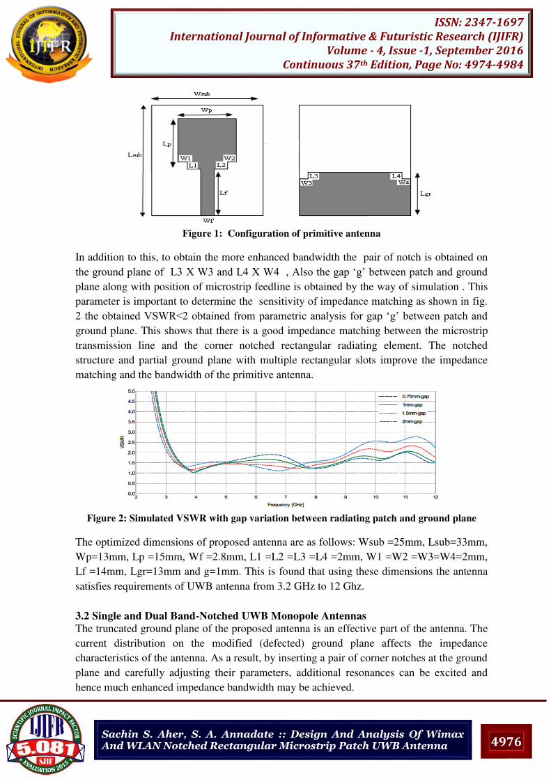
Figure 1: Configuration of primitive antenna
In addition to this, to obtain the more enhanced bandwidth the pair of notch is obtained on
the ground plane of δ3 X W3 and δ4 X W4 , Also the gap ‘g’ between patch and ground plane along with position of microstrip feedline is obtained by the way of simulation . This
parameter is important to determine the sensitivity of impedance matching as shown in fig.
2 the obtained VSWR<2 obtained from parametric analysis for gap ‘g’ between patch and ground plane. This shows that there is a good impedance matching between the microstrip
transmission line and the corner notched rectangular radiating element. The notched
structure and partial ground plane with multiple rectangular slots improve the impedance
matching and the bandwidth of the primitive antenna.
Figure 2: Simulated VSWR with gap variation between radiating patch and ground plane
The optimized dimensions of proposed antenna are as follows: Wsub =25mm, Lsub=33mm,
Wp=13mm, Lp =15mm, Wf =2.8mm, L1 =L2 =L3 =L4 =2mm, W1 =W2 =W3=W4=2mm,
Lf =14mm, Lgr=13mm and g=1mm. This is found that using these dimensions the antenna
satisfies requirements of UWB antenna from 3.2 GHz to 12 Ghz.
3.2 Single and Dual Band-Notched UWB Monopole Antennas
The truncated ground plane of the proposed antenna is an effective part of the antenna. The
current distribution on the modified (defected) ground plane affects the impedance
characteristics of the antenna. As a result, by inserting a pair of corner notches at the ground
plane and carefully adjusting their parameters, additional resonances can be excited and
hence much enhanced impedance bandwidth may be achieved.
4977
ISSN: 2347-1697
International Journal of Informative & Futuristic Research (IJIFR)
Volume - 4, Issue -1, September 2016
Continuous 37th Edition, Page No: 4974-4984
Sachin S. Aher, S. A. Annadate :: Design And Analysis Of Wimax And WLAN Notched Rectangular Microstrip Patch UWB Antenna
The proposed antenna structure is simulated using method of moment (MoM) software,
CADFEKO Version 6.2[15]. Once the UWB bandwidth is achieved, to obtain notched band
properties of the proposed antenna, current distribution of an antenna plays an important
role which is the advantage of method of moment analysis where we can analyze actual
antenna radiation. While performing the simulation it is observed that the antenna has
maximum current distribution on the patch at 3.5GHz for designing of the stop band
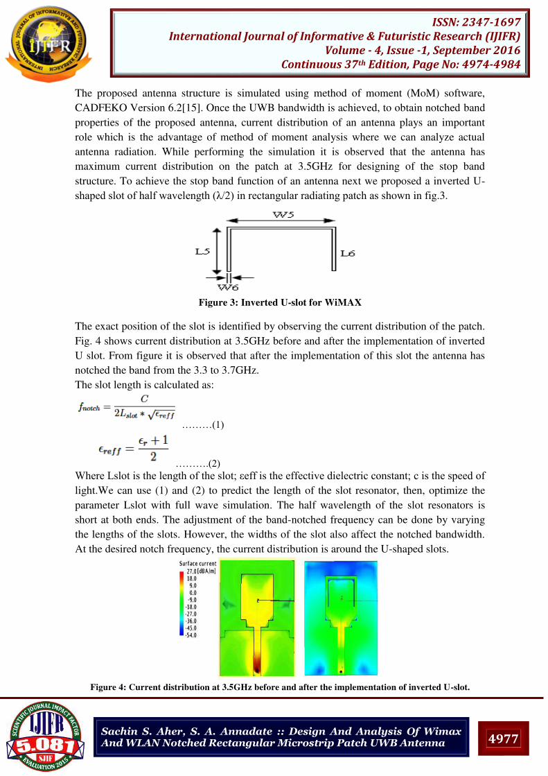
structure. To achieve the stop band function of an antenna next we proposed a inverted U-
shaped slot of half wavelength (λ/2) in rectangular radiating patch as shown in fig.3.
Figure 3: Inverted U-slot for WiMAX
The exact position of the slot is identified by observing the current distribution of the patch.
Fig. 4 shows current distribution at 3.5GHz before and after the implementation of inverted
U slot. From figure it is observed that after the implementation of this slot the antenna has
notched the band from the 3.3 to 3.7GHz.
The slot length is calculated as:
………(1)
……….(2) Where δslot is the length of the slot; eff is the effective dielectric constant; c is the speed of light.We can use (1) and (2) to predict the length of the slot resonator, then, optimize the
parameter Lslot with full wave simulation. The half wavelength of the slot resonators is
short at both ends. The adjustment of the band-notched frequency can be done by varying
the lengths of the slots. However, the widths of the slot also affect the notched bandwidth.
At the desired notch frequency, the current distribution is around the U-shaped slots.
Figure 4: Current distribution at 3.5GHz before and after the implementation of inverted U-slot.
4978
ISSN: 2347-1697
International Journal of Informative & Futuristic Research (IJIFR)
Volume - 4, Issue -1, September 2016
Continuous 37th Edition, Page No: 4974-4984
Sachin S. Aher, S. A. Annadate :: Design And Analysis Of Wimax And WLAN Notched Rectangular Microstrip Patch UWB Antenna
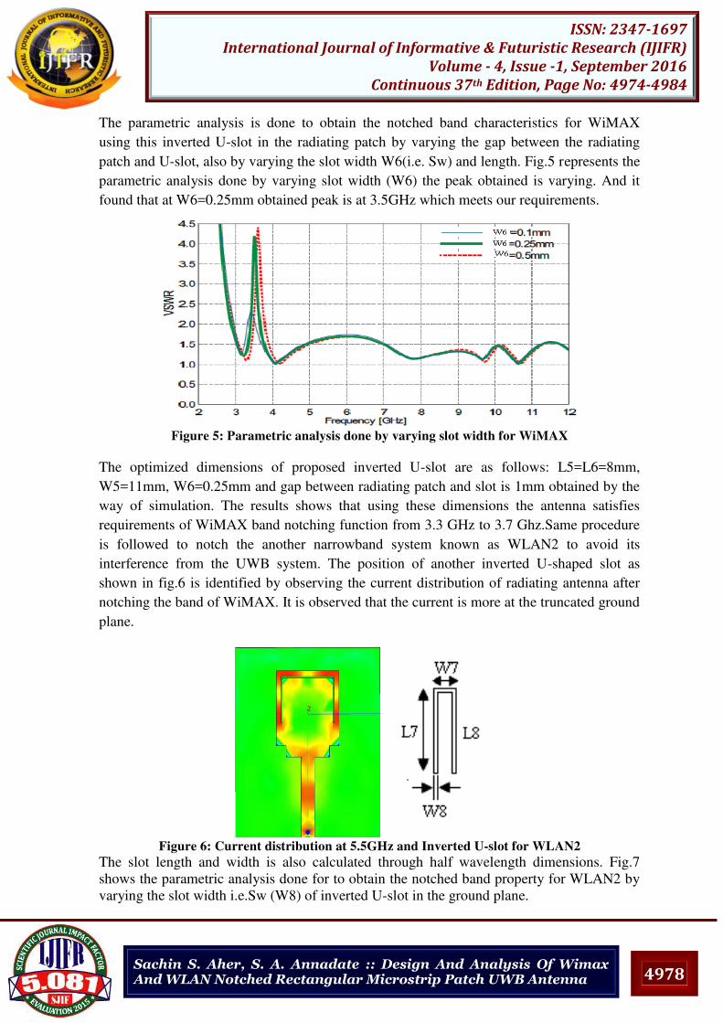
The parametric analysis is done to obtain the notched band characteristics for WiMAX
using this inverted U-slot in the radiating patch by varying the gap between the radiating
patch and U-slot, also by varying the slot width W6(i.e. Sw) and length. Fig.5 represents the
parametric analysis done by varying slot width (W6) the peak obtained is varying. And it
found that at W6=0.25mm obtained peak is at 3.5GHz which meets our requirements.
Figure 5: Parametric analysis done by varying slot width for WiMAX
The optimized dimensions of proposed inverted U-slot are as follows: L5=L6=8mm,
W5=11mm, W6=0.25mm and gap between radiating patch and slot is 1mm obtained by the
way of simulation. The results shows that using these dimensions the antenna satisfies
requirements of WiMAX band notching function from 3.3 GHz to 3.7 Ghz.Same procedure
is followed to notch the another narrowband system known as WLAN2 to avoid its
interference from the UWB system. The position of another inverted U-shaped slot as
shown in fig.6 is identified by observing the current distribution of radiating antenna after
notching the band of WiMAX. It is observed that the current is more at the truncated ground
plane.
Figure 6: Current distribution at 5.5GHz and Inverted U-slot for WLAN2
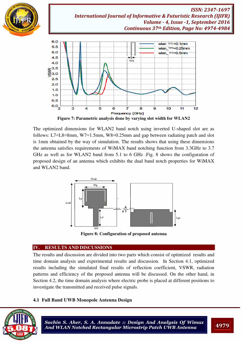
The slot length and width is also calculated through half wavelength dimensions. Fig.7
shows the parametric analysis done for to obtain the notched band property for WLAN2 by
varying the slot width i.e.Sw (W8) of inverted U-slot in the ground plane.
4979
ISSN: 2347-1697
International Journal of Informative & Futuristic Research (IJIFR)
Volume - 4, Issue -1, September 2016
Continuous 37th Edition, Page No: 4974-4984
Sachin S. Aher, S. A. Annadate :: Design And Analysis Of Wimax And WLAN Notched Rectangular Microstrip Patch UWB Antenna
Figure 7: Parametric analysis done by varying slot width for WLAN2
The optimized dimensions for WLAN2 band notch using inverted U-shaped slot are as
follows: L7=L8=8mm, W7=1.5mm, W8=0.25mm and gap between radiating patch and slot
is 1mm obtained by the way of simulation. The results shows that using these dimensions
the antenna satisfies requirements of WiMAX band notching function from 3.3GHz to 3.7
GHz as well as for WLAN2 band from 5.1 to 6 GHz .Fig. 8 shows the configuration of
proposed design of an antenna which exhibits the dual band notch properties for WiMAX
and WLAN2 band.
Figure 8: Configuration of proposed antenna
IV. RESULTS AND DISCUSSIONS
The results and discussion are divided into two parts which consist of optimized results and
time domain analysis and experimental results and discussion. In Section 4.1, optimized
results including the simulated final results of reflection coefficient, VSWR, radiation
patterns and efficiency of the proposed antenna will be discussed. On the other hand, in
Section 4.2, the time domain analysis where electric probe is placed at different positions to
investigate the transmitted and received pulse signals.
4.1 Full Band UWB Monopole Antenna Design

4980
ISSN: 2347-1697
International Journal of Informative & Futuristic Research (IJIFR)
Volume - 4, Issue -1, September 2016
Continuous 37th Edition, Page No: 4974-4984
Sachin S. Aher, S. A. Annadate :: Design And Analysis Of Wimax And WLAN Notched Rectangular Microstrip Patch UWB Antenna
Based on the optimized parameters of the proposed dual band-notched planar
rectangular UWB antenna with truncated ground plane. We obtained the bandwidth of an
antenna rages from 3GHz to 12GHz. Fig.9 and 10 shows the reflection coefficient <-10dB
and VSWR<2 obtained after the inserting two inverted U-slots, one in the rectangular
radiating patch and another on the truncated ground plane which leads to obtain the proper
impedance bandwidth.
It can be seen that the simulated impedance bandwidth for reflection coefficient< -10dB is
from 3 to 12 GHz, except the bands of 3.3-3.7GHz (required for WiMAX) and 5.1-6GHz
(required for WLAN2). While designing by the way of simulation it is also clearly seen that
by using this filtering structure, the lowest frequency of the antenna is significantly
decreased from 3.2 to 3 GHz.
Figure 9: Simulated reflection coefficient <-10dB
Figure 10: Simulated VSWR < 2
Figure 11: Prototype of a proposed system
4981
ISSN: 2347-1697
International Journal of Informative & Futuristic Research (IJIFR)
Volume - 4, Issue -1, September 2016
Continuous 37th Edition, Page No: 4974-4984
Sachin S. Aher, S. A. Annadate :: Design And Analysis Of Wimax And WLAN Notched Rectangular Microstrip Patch UWB Antenna
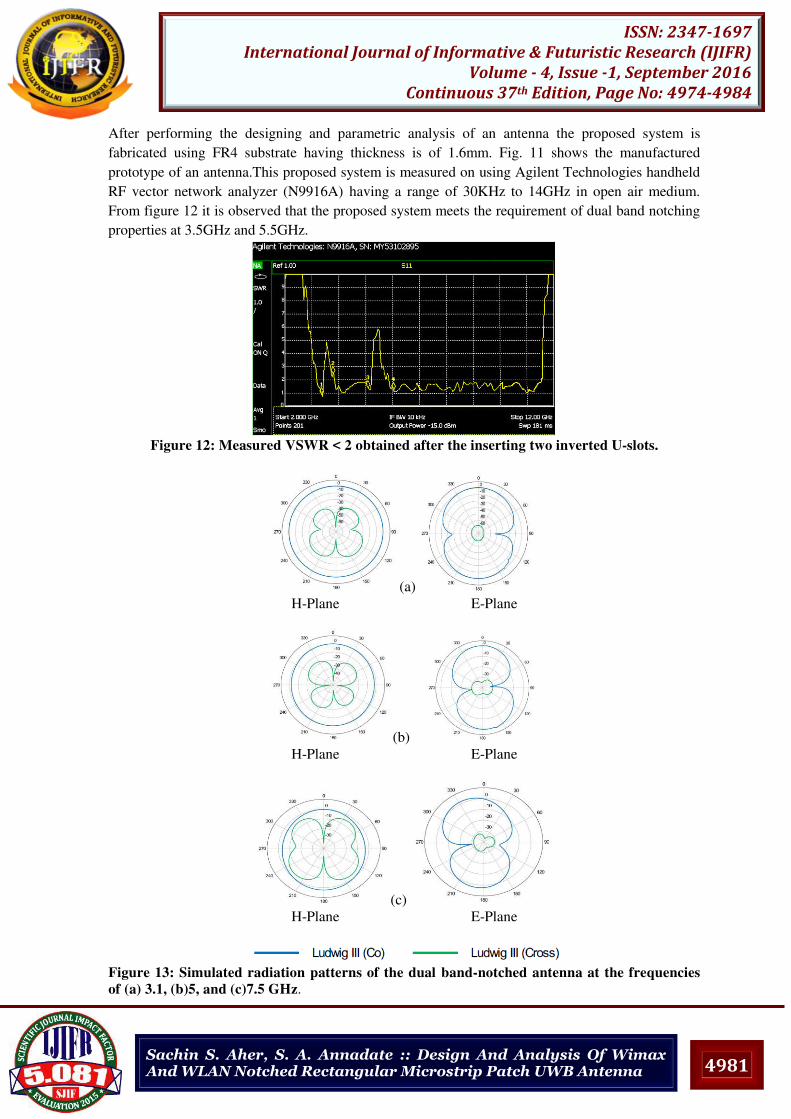
After performing the designing and parametric analysis of an antenna the proposed system is
fabricated using FR4 substrate having thickness is of 1.6mm. Fig. 11 shows the manufactured
prototype of an antenna.This proposed system is measured on using Agilent Technologies handheld
RF vector network analyzer (N9916A) having a range of 30KHz to 14GHz in open air medium.
From figure 12 it is observed that the proposed system meets the requirement of dual band notching
properties at 3.5GHz and 5.5GHz.
Figure 12: Measured VSWR < 2 obtained after the inserting two inverted U-slots.
(a)
H-Plane E-Plane
(b)
H-Plane E-Plane
(c)
H-Plane E-Plane
Figure 13: Simulated radiation patterns of the dual band-notched antenna at the frequencies
of (a) 3.1, (b)5, and (c)7.5 GHz.

4982
ISSN: 2347-1697
International Journal of Informative & Futuristic Research (IJIFR)
Volume - 4, Issue -1, September 2016
Continuous 37th Edition, Page No: 4974-4984
Sachin S. Aher, S. A. Annadate :: Design And Analysis Of Wimax And WLAN Notched Rectangular Microstrip Patch UWB Antenna
Fig.13 shows simulated co-polarization and cross polarization obatained across the E-plane
and H-plane. As the microstrip patch antenna has the advantage of its smaller cross
polarization [1]. Our antenna fulfills such requirements of polarization. The antenna has
shown similar characteristics in case of reflection coefficient and VSWR to get dual notched
bands.The simulated efficiency of an antenna is decreased at the higher edges of frequency
due to the lossy substrate and it is upto 70%. Fig. 14 shows the graph of frequency versus
efficiency of an antenna obtained by performing simulation.
Figure 14: Simulated efficiency of an antenna
The figure indicates that the realized dualband-notched antenna has good efficiency flatness
except in two notched bands. Therefore, these two inverted U-shaped slots will not have
negative effect on the radiation performance of the antenna, in UWB band.
4.2. Time Domain Analysis
As UWB antennas are inspired by transient pulse (such as Gaussian pulse), waveform
response provides constructive recognition on antennas time-domain performance is
favourable. Therefore, waveform response of the antenna is demonstrated in this section for
comparison. In order to validate the efficiency of the antenna, the pulse base signal is
excited with Gaussian pulse. It can be related to the dispersion of receive signal compared
to transmitter signal. Figure 15 shows the radiated E field which is virtually place probe in
simulation to study the effect of radiated signal.
Figure 15: Time domain analysis for transmitted and received pulse
4983
ISSN: 2347-1697
International Journal of Informative & Futuristic Research (IJIFR)
Volume - 4, Issue -1, September 2016
Continuous 37th Edition, Page No: 4974-4984
Sachin S. Aher, S. A. Annadate :: Design And Analysis Of Wimax And WLAN Notched Rectangular Microstrip Patch UWB Antenna
From this figure, the antenna is fixed at azimuth angle of 90o, It is proved that the proposed
antenna has good potential in transmitting UWB signals with minimum distortion.
Furthermore, the time domain UWB pulse signal received by the electric probe shows stable
performance where the received pulse signal is almost identical to the transmitted pulse
signal.[15-17]
V. CONCLUSION
A dual band notched compact planar rectangular radiating patch antenna with truncated
ground plane is presented. By introducing the corner notches on both at rectangular
radiating element and at partial ground plane, a wideband impedance matching is achieved.
To mitigate the potential interference between the UWB systems and narrowband systems
such as WiMAX (3.3-3.7GHz) and WLAN (5.1-6GHz), two inverted U-shaped slots are
added for band rejection. The simulated results shows that the antenna not only has dual
notched bands over an ultra-wide operation band but also have a good radiation pattern. The
proposed planar antenna is easily integrated with RF/microwave circuits for low cost
manufacturing and suitable for various UWB applications.
VI. REFERENCES [1] C. A. Balanis,” Antenna Theory: Analysis and Design”, Publishing House 2nd Edition.
[2] FCC, “First Report and Order on Ultra-Wideband Technology,” Tech. Rep., 2002.
[3] D. J. Daniels, “Surface-penetrating radar,” Proc. Inst. Elect. Eng., ser. 6, pp. 72–93, 1996.
[4] Z. N. Chen, M.W. Y. Chia, and M. J. Ammann, “Optimization and comparisonof broadband
monopole antennas’’Proc. Inst. Elect. Eng., vol. 150, no.6, pp. 429–435, Dec. 2003.
[5] N. P. Agrawall, G. Kumar, and K. P. Ray, “Wide-band planar monopole antennas,” IEEE
Trans. Antennas Propag., vol. 46, no. 2, pp. 294–295, Feb. 1998.
[6] A. M. Abbosh, “Design of a CPW-Fed Band-Notched UWB Antenna Using a Feeder-
Embedded Slot Line Resonator,” International Journal of Antennas and Pro- pagation, Vol.
2008, 2008, Article ID: 564317
[7] H. J. Zhou, Q. Z. Liu, Y. Z. Yin and W. B. Wei, “Study of the Band-Notch Function for
Swallow-Tailed Planar Monopole Antennas,” Progress in Electromagnetic Re-search, PIER 77,
2007, pp. 55-65.
[8] N. Bayatmaku, M. Naser-Moghadasi M. Jahanbakht and Bal S. Virdee, “A Compact Ultra Wideband Printed Spi-ral Slot Antenna with Band Notched Characteristics,” Journal of
Telecommunications, Vol. 3, No. 2, 2010, pp. 29-31.
[9] N. H. M. Sobli and H. E. Abd-El-Raouf, “Design of a Compact Printed Band-Notched Antenna
for Ultra Wide-band Communications,” Progress in Electromagnetic Research M, Vol. 3, 2008,
pp. 57-78. doi:10.2528/PIERM08051203
[10] R. Fallahi, A.-A. Kalteh and M. G. Roozbahani, “A Novel UWB Elliptical Slot Antenna with Band-Notched Characteristics,” Progress in Electromagnetic Research, PIER 82, 2008, pp.127-
136, doi:10.2528 / PIER 08022603
[11] A. A. Lotfi Neyestanak, M. R. Azadi Naeini, M. Naser- Moghadasi and Gh. Dadashzadeh,
“Band Notched CPW Fed Hexagonal Fractal Antenna,” Journal of Electro-magnetic Waves
and Applications, Vol. 23, No. 17, 2009, pp. 2461- 2470.
[12] Reza Zaker, Changiz Ghobadi, and Javad Nourinia, “Bandwidth Enhancement of Novel Compact Single and Dual Band-Notched Printed Monopole Antenna With a Pair of L-Shaped
Slots”, IEEE Trans. Antennas Propagation, Vol.57,No.12, Nov2009, pp. 3978-3983
[13] K. H. Kim, Y. J. Cho, S. H. Hwang and S. O. Park, “Band-notched UWB planar monopole
antenna with two parasitic patches”, Electronics Letters, 7th July 2005 Vol. 41 No. 14
4984
ISSN: 2347-1697
International Journal of Informative & Futuristic Research (IJIFR)
Volume - 4, Issue -1, September 2016
Continuous 37th Edition, Page No: 4974-4984
Sachin S. Aher, S. A. Annadate :: Design And Analysis Of Wimax And WLAN Notched Rectangular Microstrip Patch UWB Antenna
[14] Q. X. Chu, and Y. Y. Yang, “A compact ultrawideband antenna with 3.4/5.5 GHz dual band-
notched characteristics,” IEEE Trans. Antennas Propagation, Vol. 56, no. 12, pp. 3637-3644,
2008
[15] K. S. Lim, M. Nagalingam, and C. P. Tan, “Design And Construction Of Microstrip Uwb
Antenna With Time Domain Analysis” Progress In Electromagnetics Research M, Vol. 3, 153–164, 2008
[16] δeonardo δizzi, δuca εanica, and Andrea εassa, “Time Domain Analysis for UWB Antenna
Synthesis”, Proceedings of the 39th European Microwave Conference, 978-2-87487-011-8, PP.
93-96, 29 September - 1 October 2009
[17] Lin Peng and Chengli Ruan, “Design And Time-Domain Analysis Of Compact Multi-Band-
Notched Uwb Antennas With Ebg Structures” Progress In Electromagnetics Research B, Vol.
47, 339–357, 2013
[18] CADFEKO Simulation Software Version 6.2
To Cite This Article
Aher, S. S., & Annadate, S. A. (2016). Design And Analysis Of Wimax And WLAN
Notched Rectangular Microstrip Patch UWB Antenna . International Journal of
Informative & Futuristic Research (ISSN: 2347-1697), Vol. 4 No. (1), September 2016,
pp. 4974-4984. PaperID:IJIFR/V4/E1/042. Retrieved On September 30, 2016, from
http://ijifr.com/searchjournal.aspx.