design and construct a phase difference laser range sensor
TRANSCRIPT
Alan Kilian Fall 2009
Design and Construct a Phase Difference LASER Range Sensor.
1
Introduction:
This project is intended as a demonstration of my skills in three specific areas: 1. Evaluating sensor design principals.2. Implementing sensors.3. Testing sensors.
For this report, I will research possible methods of constructing a phase-difference LASER range finder, I will select a method, I will implement and I will test that method. I will explain the design choices I made and the results of those decisions.
1) Evaluating sensor design principals:
• Demonstrate understanding of the design principles of a phase difference LASER range finder.
• Determine a measuring system that allows the Phase Difference LASER Range Sensor to measure the distance to an object.
A Phase Difference LASER Range Sensor uses a LASER to produce a bright beam of light. This beam of light is made to change its brightness by an electronic signal. This beam of light travels from the LASER through space at the speed of light and reflects off the object of which the distance is being measured and returns to a light detector located next to the LASER. By measuring the difference in phase between the outgoing light and the reflected light and knowing the speed of light in air, the distance to the object can be determined.
Figure 1 below shows a conceptual diagram of a phase difference LASER range finder. The system consists of a three systems:
1. A system to produce modulated LASER light2. A system for detecting and amplifying light signals3. A system for comparing the phase difference between these two signals.
The system for producing modulated LASER light consists of a reference signal source (in this case, a 6 megahertz crystal oscillator module) which directly controls the LASER diode producing a modulated light signal.
The system for detecting and amplifying the reflected light signal consists of a photo detector and amplifier module.
The system for comparing the two signals and measuring the phase difference between them consists of a phase detector and a volt meter.
2
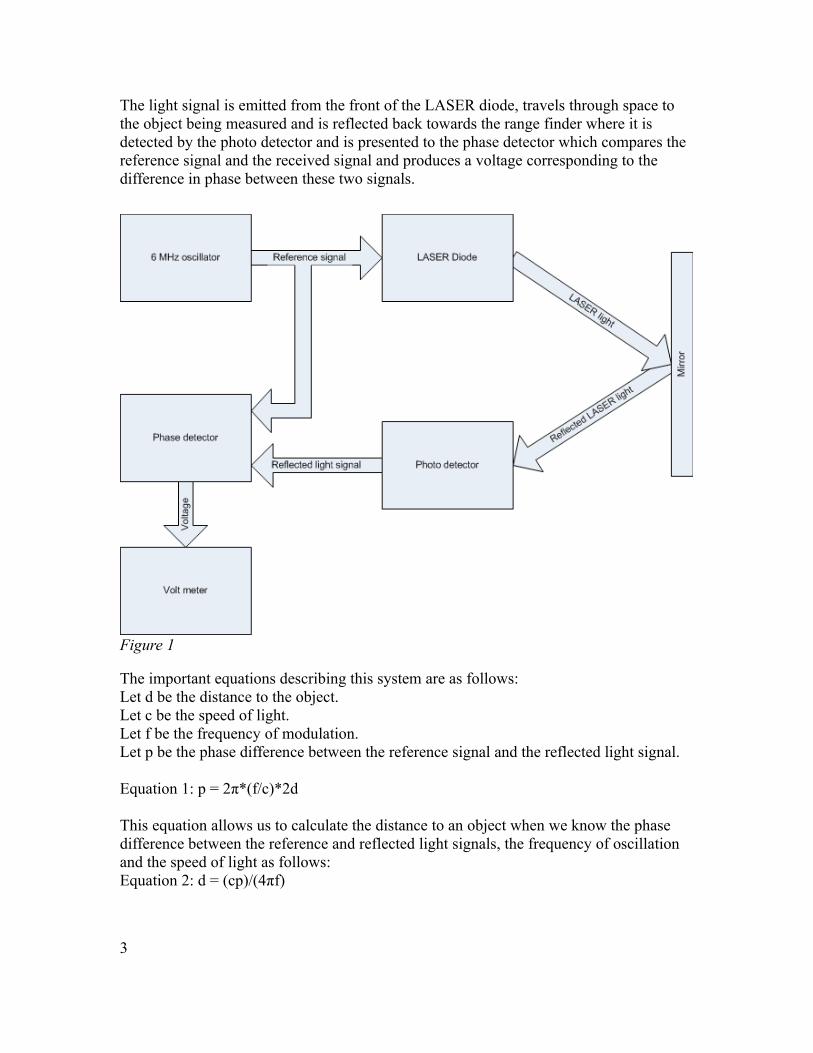
The light signal is emitted from the front of the LASER diode, travels through space to the object being measured and is reflected back towards the range finder where it is detected by the photo detector and is presented to the phase detector which compares the reference signal and the received signal and produces a voltage corresponding to the difference in phase between these two signals.
Figure 1
The important equations describing this system are as follows:Let d be the distance to the object.Let c be the speed of light.Let f be the frequency of modulation.Let p be the phase difference between the reference signal and the reflected light signal.
Equation 1: p = 2π*(f/c)*2d
This equation allows us to calculate the distance to an object when we know the phase difference between the reference and reflected light signals, the frequency of oscillation and the speed of light as follows: Equation 2: d = (cp)/(4πf)
3

• Determining a suitable reference oscillator frequency.The designer of this system has only a single parameter which can be selected. That parameter is the frequency of the reference oscillator. All other parameters are determined by external conditions. Determining a value for the reference oscillator frequency requires selecting the desired range of detectable distances. For this project, I have determined that the system should be able to determine the distance to the front of a vehicle as it drives into a garage to allow a driver to park their vehicle with enough accuracy to avoid having the garage door hit the back of the vehicle after parking. For this purpose, I have determined that a desirable range of distances is from 1 meter to 4 meters with an accuracy of 0.1 meters. This range and accuracy should be adequate to perform this task.
A further design constraint is that the phase detector can only determine the phase difference between 0 and 2π radians. This constraint further restricts the choice of reference oscillator frequency since any phase differences greater than 2π radians will be indistinguishable from phase differences in the 0 to 2π range.
To determine a suitable reference oscillator frequency, I first determined the expected phase difference to an object at the maximum desired distance for a variety of reference oscillator frequencies using Equation 1: p = 2π*(f/c)*2*4meters substituting and simplifying Equation 1 results in:Equation 3: p = (16πf)/cIf we let p = 2π radians and c=299,792,458 meters per second, we get f=3.74*10^7 Hz or f=37,400,000 Hz Therefore the maximum frequency the reference oscillator can be is 37 Mhz to prevent the phase difference from becoming greater than 2π radians at a distance of 4 meters range.
Another consideration in the choice of reference oscillator frequency is the the higher the reference oscillator frequency, the larger the phase difference is per unit of change in distance. With the example of 37 MHz reference oscillator frequency, using Equation #1 we can calculate that the system will return a phase change of 0.16 radians with a change of distance of 0.1 Meters. Using this information, I can determine that the phase detector and volt meter must be able to distinguish a change of 0.16 radians in order to meet the minimum required resolution. Using a lower frequency reference oscillator will require a system that can distinguish smaller differences in phase. An extreme example is if the reference oscillator is 1 MHz, the phase difference between two objects 0.1 meters apart is 0.004 Radians. Both the maximum range I wish to detect and the minimum phase difference I can detect will determine acceptable reference oscillator frequencies.
Determining a suitable phase detector.
Using an Internet search for the phrase phase detector led me to many reference articles and explanatory websites describing phase detectors. The Wikipedia entry on phase detectors led me to the term Digital Phase Detector.
Quoting from the Wikipedia article on phase detector:
4
“A phase detector suitable for square wave signals can be made from an exclusive-OR (XOR) logic gate. When the two signals being compared are completely in-phase, the XOR gate's output will have a constant level of zero. When the two signals differ in phase by 1°, the XOR gate's output will be high for 1/180th of each cycle — the fraction of a cycle during which the two signals differ in value. When the signals differ by 180° — that is, one signal is high when the other is low, and vice versa — the XOR gate's output remains high throughout each cycle.
The XOR detector compares well to the analog mixer in that it locks near a 90° phase difference and has a square-wave output at twice the reference frequency. The square-wave changes duty-cycle in proportion to the phase difference resulting. Applying the XOR gate's output to a low-pass filter results in an analog voltage that is proportional to the phase difference between the two signals. It requires inputs that are symmetrical square waves, or nearly so. The remainder of its characteristics are very similar to the analog mixer for capture range, lock time, reference spurious and low-pass filter requirements.”
This type of phase detector has several characteristics ideal for my system:
• It is suitable for square wave signals. Since I will be directly driving the LASER diode with the output of a square wave oscillator circuit, both the reference signal and the reflected light signal are square waves.
• It has a square wave output at twice the input frequency. This characteristic makes it easier to perform a low pass filter operation on the phase difference information and have a fast response to changes in phase difference.
This type of detector seemed ideal for my system and I searched for such a detector. This search led me to an integrated circuit manufactured by many different silicon vendors called a 4046 phase-locked-loop with lock detector integrated circuit.
2) Implementing sensors.
• Design and construct a Phase Difference LASER Range Sensor.
I located a 4046 phase-locked loop IC in my supply of parts and built a circuit to test its performance. This circuit is shown in Circuit #1 below.
5
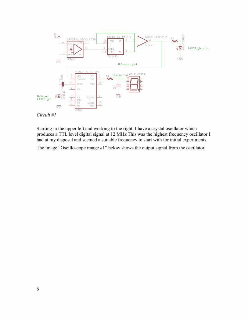
Starting in the upper left and working to the right, I have a crystal oscillator which produces a TTL level digital signal at 12 MHz This was the highest frequency oscillator I had at my disposal and seemed a suitable frequency to start with for initial experiments.
The image “Oscilloscope image #1” below shows the output signal from the oscillator.
6
Circuit #1
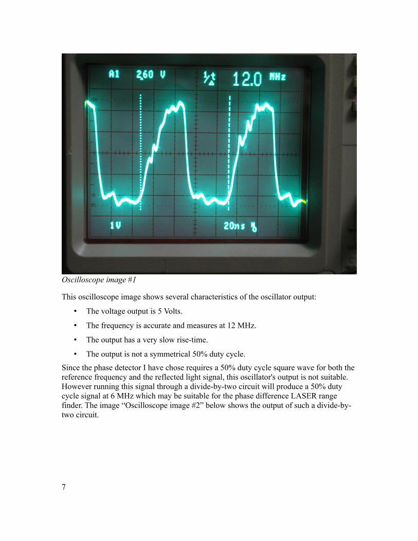
This oscilloscope image shows several characteristics of the oscillator output:
• The voltage output is 5 Volts.
• The frequency is accurate and measures at 12 MHz.
• The output has a very slow rise-time.
• The output is not a symmetrical 50% duty cycle.
Since the phase detector I have chose requires a 50% duty cycle square wave for both the reference frequency and the reflected light signal, this oscillator's output is not suitable. However running this signal through a divide-by-two circuit will produce a 50% duty cycle signal at 6 MHz which may be suitable for the phase difference LASER range finder. The image “Oscilloscope image #2” below shows the output of such a divide-by-two circuit.
7
Oscilloscope image #1

This oscilloscope image shows several improved characteristics of the oscillator output:
• The voltage output is 5 Volts.
• The frequency is accurate and measures at 6 MHz.
• The output has a very fast rise-time.
• The output is a symmetrical 50% duty cycle.
8
Oscilloscope image #2
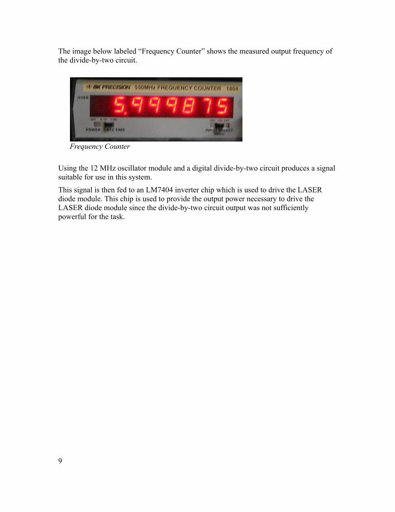
The image below labeled “Frequency Counter” shows the measured output frequency of the divide-by-two circuit.
Using the 12 MHz oscillator module and a digital divide-by-two circuit produces a signal suitable for use in this system.
This signal is then fed to an LM7404 inverter chip which is used to drive the LASER diode module. This chip is used to provide the output power necessary to drive the LASER diode module since the divide-by-two circuit output was not sufficiently powerful for the task.
9
Frequency Counter
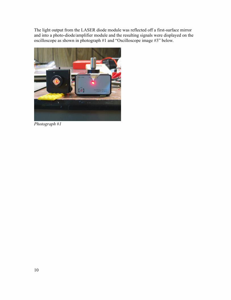
The light output from the LASER diode module was reflected off a first-surface mirror and into a photo-diode/amplifier module and the resulting signals were displayed on the oscilloscope as shown in photograph #1 and “Oscilloscope image #3” below.
Photograph #1
10

This image shows the reference oscillator signal in the lower trace and the reflected light signal in the upper trace.
Several important characteristics are:
• The reflected light is detected and amplified by the photo detector/amplifier module.
• The signal from the photo detector/amplifier module is a 50% duty cycle square wave with a moderate amount of distortion.
• The phase-difference between the reference signal and the reflected light signal is small. From this image I estimate the time delta between rising edges to be 10-15 nanoseconds. This corresponds to a phase difference of between 0.4 and 0.6 radians. This offset will be measured and compensated for when determining the actual phase-difference.
11
Oscilloscope image #3

The remaining circuitry in the lower right of the schematic is a low pass filter and a voltage measuring device. The complete circuit is shown in photograph #2 below.
12
Photograph #2

Photograph #3 below shows the Phase Difference LASER Range Finder during testing.
Photograph #3
3) Testing Sensors:• Test the Phase Difference LASER Range Sensor’s measurement accuracy.
I gathered data from the LASER Range finder by moving a first-surface mirror various distances away from the LASER and photo detector and recording the voltage produced by the phase detector. This data is in the table below.
13

Distance in feet
Measured voltage
2 1.5
3 1.67
4 1.81
5 1.94
6 2.05
7 2.19
8 2.33
9 2.45
10 2.59
11 2.71
12 2.85
13 2.97
14 3.11
15 3.19
The phase detector output shows a linear relationship with distance as expected. To verify the scale is expected, Since the plot shows some non linearity at the near and far extreme
14
0 2 4 6 8 10 12 14 160
0.5
1
1.5
2
2.5
3
3.5
Distance vs. phase detector output
One way distance in feet
Ph
ase
de
tect
or
ou
tpu
t vo
ltag
e

range of distances, I compared the phase at a distance of 3 feet with the phase at a distance of 14 feet as follows:
• Voltage at 14 feet minus Voltage at 3 feet is 3.11V – 1.67V = 1.44 Volts.• The phase detector's scaling is 5 volts per π radians.• This means the phase change is (1.44V/5V) * π radians = 0.9 radians.• Using Equation #2 d = (cp)/(4πf) and substituting p = 0.9 radians, I calculate the
change in distance to be 3.57 meters.• The measured change in distance is (14 feet – 3 feet) = 11 feet (3.35 meters)• The error in the range finder's measurement is 3.57 meters – 3.35 meters = 0.22
meters over the full range of measurement distance. This is larger than my design goal of 0.1 Meters.
To see if this magnitude of error is related to the precision of my Vvltage measurement, I calculated the voltage corresponding to this distance:
• Using Equation #1 p = 2π*(f/c)*2d and setting d=0.22 Meters, I calculate the error in phase of 0.05 radians.
• Using the phase detector's scale of 5 volts per π radians, 0.05 radians is 0.03 Volts.• An error in measurement of 0.03 Volts is larger than I expected given the
precision of the volt meter I was using, so I do not believe this error is due to voltage measurement error.
15

I next created a spreadsheet using the 14 phase measurement values and the known distances and calculated the phase-change between adjacent measurements and compared the change in distance with the known change in distance.
The rightmost column shows that while moving the mirror 0.304 Meters (1 Foot) at a time and using the difference between the two measured phases, the error in position change in Meters is less than half of my design goal of 0.1 Meters for all but the first and last measurement.
Possible explanations for this error is:• The frequency of the crystal oscillator changes with temperature. I did not record
this possible frequency change during the time I made my measurements. If it changed, the accuracy of the Phase Difference LASER Range Finder would change also.
• I placed the first-surface mirror on a tripod and lined it up with distance marks on the floor visually. Any inaccuracy in this measurement would be reflected in inaccuracies in the output of the Phase Difference LASER Range Finder.
4) Suitability to the task of assisting in parking a car in a garage:
This system was able to meet the minimum accuracy in distance measurement I set out at the beginning of the project. It may be able to be improved sufficiently through the changes listed below.
16
2 1.53 1.67 0.170 0.107 0.425 1.393 -0.1204 1.81 0.140 0.088 0.350 1.147 -0.0455 1.94 0.130 0.082 0.325 1.065 -0.0206 2.05 0.110 0.069 0.275 0.901 0.0307 2.19 0.140 0.088 0.350 1.147 -0.0458 2.33 0.140 0.088 0.350 1.147 -0.0459 2.45 0.120 0.075 0.300 0.983 0.005
10 2.59 0.140 0.088 0.350 1.147 -0.04511 2.71 0.120 0.075 0.300 0.983 0.00512 2.85 0.140 0.088 0.350 1.147 -0.04513 2.97 0.120 0.075 0.300 0.983 0.00514 3.11 0.140 0.088 0.350 1.147 -0.04515 3.19 0.080 0.050 0.200 0.656 0.105
Distance (Feet)
Measured voltage
Delta voltage
Phase change
Distance (Meters)
Distance (Feet)
Distance Error (Meters)
Further investigations:
If I were to continue this project further, I would make the following improvements in the system:
Optical:
• I would build an optical system so that the LASER output beam and the reflected light beam to the photo detector were coaxial. This would eliminate errors in path length due to the different locations of the LASER diode and the photo detector.
• I would build a lens system for gathering the reflected light and focusing it on the photo detector. This would make it possible to detect the reflected light from an actual vehicle license plate rather than the first-surface mirror I needed to use.
Electrical:
• I would build a temperature-stabilized frequency source to eliminate any source of errors due to changing frequencies.
• I would improve the electrical design to allow much higher frequencies to be used. This would involve selecting integrated circuits which operate at a higher frequency as well as a LASER diode which can operate at higher modulation frequencies. Operating at a higher modulation frequency would improve the resolution of the system.
Test setup:
• I would build a system to accurately place the target in a repeatable position to eliminate any errors due to measured position and to allow measurements of precision in the system.
Summary:
I researched possible phase-difference LASER range finding systems, I selected parameters appropriate to the design task, I built a phase-difference LASER range finding system, I tested its performance, I analyzed possible errors in the system, and I proposed possible improvements in the system.
17